US6616675B1 - Methods and apparatus for connecting openings formed in adjacent blood vessels or other anatomical structures - Google Patents
Methods and apparatus for connecting openings formed in adjacent blood vessels or other anatomical structuresDownload PDFInfo
- Publication number
- US6616675B1 US6616675B1US09/117,520US11752099AUS6616675B1US 6616675 B1US6616675 B1US 6616675B1US 11752099 AUS11752099 AUS 11752099AUS 6616675 B1US6616675 B1US 6616675B1
- Authority
- US
- United States
- Prior art keywords
- tube
- anatomical structure
- engagement
- connector
- configuration
- Prior art date
- Legal status (The legal status is an assumption and is not a legal conclusion. Google has not performed a legal analysis and makes no representation as to the accuracy of the status listed.)
- Expired - Lifetime
Links
Images


Classifications
- A—HUMAN NECESSITIES
- A61—MEDICAL OR VETERINARY SCIENCE; HYGIENE
- A61B—DIAGNOSIS; SURGERY; IDENTIFICATION
- A61B1/00—Instruments for performing medical examinations of the interior of cavities or tubes of the body by visual or photographical inspection, e.g. endoscopes; Illuminating arrangements therefor
- A61B1/313—Instruments for performing medical examinations of the interior of cavities or tubes of the body by visual or photographical inspection, e.g. endoscopes; Illuminating arrangements therefor for introducing through surgical openings, e.g. laparoscopes
- A61B1/3137—Instruments for performing medical examinations of the interior of cavities or tubes of the body by visual or photographical inspection, e.g. endoscopes; Illuminating arrangements therefor for introducing through surgical openings, e.g. laparoscopes for examination of the interior of blood vessels
- A—HUMAN NECESSITIES
- A61—MEDICAL OR VETERINARY SCIENCE; HYGIENE
- A61B—DIAGNOSIS; SURGERY; IDENTIFICATION
- A61B17/00—Surgical instruments, devices or methods
- A61B17/11—Surgical instruments, devices or methods for performing anastomosis; Buttons for anastomosis
- A—HUMAN NECESSITIES
- A61—MEDICAL OR VETERINARY SCIENCE; HYGIENE
- A61B—DIAGNOSIS; SURGERY; IDENTIFICATION
- A61B18/00—Surgical instruments, devices or methods for transferring non-mechanical forms of energy to or from the body
- A61B18/04—Surgical instruments, devices or methods for transferring non-mechanical forms of energy to or from the body by heating
- A61B18/12—Surgical instruments, devices or methods for transferring non-mechanical forms of energy to or from the body by heating by passing a current through the tissue to be heated, e.g. high-frequency current
- A61B18/14—Probes or electrodes therefor
- A61B18/1442—Probes having pivoting end effectors, e.g. forceps
- A61B18/1445—Probes having pivoting end effectors, e.g. forceps at the distal end of a shaft, e.g. forceps or scissors at the end of a rigid rod
- A—HUMAN NECESSITIES
- A61—MEDICAL OR VETERINARY SCIENCE; HYGIENE
- A61F—FILTERS IMPLANTABLE INTO BLOOD VESSELS; PROSTHESES; DEVICES PROVIDING PATENCY TO, OR PREVENTING COLLAPSING OF, TUBULAR STRUCTURES OF THE BODY, e.g. STENTS; ORTHOPAEDIC, NURSING OR CONTRACEPTIVE DEVICES; FOMENTATION; TREATMENT OR PROTECTION OF EYES OR EARS; BANDAGES, DRESSINGS OR ABSORBENT PADS; FIRST-AID KITS
- A61F2/00—Filters implantable into blood vessels; Prostheses, i.e. artificial substitutes or replacements for parts of the body; Appliances for connecting them with the body; Devices providing patency to, or preventing collapsing of, tubular structures of the body, e.g. stents
- A61F2/02—Prostheses implantable into the body
- A61F2/24—Heart valves ; Vascular valves, e.g. venous valves; Heart implants, e.g. passive devices for improving the function of the native valve or the heart muscle; Transmyocardial revascularisation [TMR] devices; Valves implantable in the body
- A61F2/2493—Transmyocardial revascularisation [TMR] devices
- A—HUMAN NECESSITIES
- A61—MEDICAL OR VETERINARY SCIENCE; HYGIENE
- A61F—FILTERS IMPLANTABLE INTO BLOOD VESSELS; PROSTHESES; DEVICES PROVIDING PATENCY TO, OR PREVENTING COLLAPSING OF, TUBULAR STRUCTURES OF THE BODY, e.g. STENTS; ORTHOPAEDIC, NURSING OR CONTRACEPTIVE DEVICES; FOMENTATION; TREATMENT OR PROTECTION OF EYES OR EARS; BANDAGES, DRESSINGS OR ABSORBENT PADS; FIRST-AID KITS
- A61F2/00—Filters implantable into blood vessels; Prostheses, i.e. artificial substitutes or replacements for parts of the body; Appliances for connecting them with the body; Devices providing patency to, or preventing collapsing of, tubular structures of the body, e.g. stents
- A61F2/95—Instruments specially adapted for placement or removal of stents or stent-grafts
- A—HUMAN NECESSITIES
- A61—MEDICAL OR VETERINARY SCIENCE; HYGIENE
- A61B—DIAGNOSIS; SURGERY; IDENTIFICATION
- A61B17/00—Surgical instruments, devices or methods
- A61B17/00234—Surgical instruments, devices or methods for minimally invasive surgery
- A—HUMAN NECESSITIES
- A61—MEDICAL OR VETERINARY SCIENCE; HYGIENE
- A61B—DIAGNOSIS; SURGERY; IDENTIFICATION
- A61B17/00—Surgical instruments, devices or methods
- A61B17/00491—Surgical glue applicators
- A—HUMAN NECESSITIES
- A61—MEDICAL OR VETERINARY SCIENCE; HYGIENE
- A61B—DIAGNOSIS; SURGERY; IDENTIFICATION
- A61B17/00—Surgical instruments, devices or methods
- A61B17/064—Surgical staples, i.e. penetrating the tissue
- A61B17/0643—Surgical staples, i.e. penetrating the tissue with separate closing member, e.g. for interlocking with staple
- A—HUMAN NECESSITIES
- A61—MEDICAL OR VETERINARY SCIENCE; HYGIENE
- A61B—DIAGNOSIS; SURGERY; IDENTIFICATION
- A61B18/00—Surgical instruments, devices or methods for transferring non-mechanical forms of energy to or from the body
- A—HUMAN NECESSITIES
- A61—MEDICAL OR VETERINARY SCIENCE; HYGIENE
- A61B—DIAGNOSIS; SURGERY; IDENTIFICATION
- A61B18/00—Surgical instruments, devices or methods for transferring non-mechanical forms of energy to or from the body
- A61B18/04—Surgical instruments, devices or methods for transferring non-mechanical forms of energy to or from the body by heating
- A61B18/12—Surgical instruments, devices or methods for transferring non-mechanical forms of energy to or from the body by heating by passing a current through the tissue to be heated, e.g. high-frequency current
- A61B18/14—Probes or electrodes therefor
- A61B18/1477—Needle-like probes
- A—HUMAN NECESSITIES
- A61—MEDICAL OR VETERINARY SCIENCE; HYGIENE
- A61B—DIAGNOSIS; SURGERY; IDENTIFICATION
- A61B18/00—Surgical instruments, devices or methods for transferring non-mechanical forms of energy to or from the body
- A61B18/04—Surgical instruments, devices or methods for transferring non-mechanical forms of energy to or from the body by heating
- A61B18/12—Surgical instruments, devices or methods for transferring non-mechanical forms of energy to or from the body by heating by passing a current through the tissue to be heated, e.g. high-frequency current
- A61B18/14—Probes or electrodes therefor
- A61B18/1492—Probes or electrodes therefor having a flexible, catheter-like structure, e.g. for heart ablation
- A—HUMAN NECESSITIES
- A61—MEDICAL OR VETERINARY SCIENCE; HYGIENE
- A61B—DIAGNOSIS; SURGERY; IDENTIFICATION
- A61B18/00—Surgical instruments, devices or methods for transferring non-mechanical forms of energy to or from the body
- A61B18/18—Surgical instruments, devices or methods for transferring non-mechanical forms of energy to or from the body by applying electromagnetic radiation, e.g. microwaves
- A61B18/20—Surgical instruments, devices or methods for transferring non-mechanical forms of energy to or from the body by applying electromagnetic radiation, e.g. microwaves using laser
- A61B18/22—Surgical instruments, devices or methods for transferring non-mechanical forms of energy to or from the body by applying electromagnetic radiation, e.g. microwaves using laser the beam being directed along or through a flexible conduit, e.g. an optical fibre; Couplings or hand-pieces therefor
- A61B18/24—Surgical instruments, devices or methods for transferring non-mechanical forms of energy to or from the body by applying electromagnetic radiation, e.g. microwaves using laser the beam being directed along or through a flexible conduit, e.g. an optical fibre; Couplings or hand-pieces therefor with a catheter
- A—HUMAN NECESSITIES
- A61—MEDICAL OR VETERINARY SCIENCE; HYGIENE
- A61B—DIAGNOSIS; SURGERY; IDENTIFICATION
- A61B17/00—Surgical instruments, devices or methods
- A61B17/00234—Surgical instruments, devices or methods for minimally invasive surgery
- A61B2017/00238—Type of minimally invasive operation
- A61B2017/00243—Type of minimally invasive operation cardiac
- A61B2017/00247—Making holes in the wall of the heart, e.g. laser Myocardial revascularization
- A61B2017/00252—Making holes in the wall of the heart, e.g. laser Myocardial revascularization for by-pass connections, i.e. connections from heart chamber to blood vessel or from blood vessel to blood vessel
- A—HUMAN NECESSITIES
- A61—MEDICAL OR VETERINARY SCIENCE; HYGIENE
- A61B—DIAGNOSIS; SURGERY; IDENTIFICATION
- A61B17/00—Surgical instruments, devices or methods
- A61B17/00491—Surgical glue applicators
- A61B2017/00504—Tissue welding
- A—HUMAN NECESSITIES
- A61—MEDICAL OR VETERINARY SCIENCE; HYGIENE
- A61B—DIAGNOSIS; SURGERY; IDENTIFICATION
- A61B17/00—Surgical instruments, devices or methods
- A61B17/064—Surgical staples, i.e. penetrating the tissue
- A61B2017/0641—Surgical staples, i.e. penetrating the tissue having at least three legs as part of one single body
- A—HUMAN NECESSITIES
- A61—MEDICAL OR VETERINARY SCIENCE; HYGIENE
- A61B—DIAGNOSIS; SURGERY; IDENTIFICATION
- A61B17/00—Surgical instruments, devices or methods
- A61B17/064—Surgical staples, i.e. penetrating the tissue
- A61B2017/0647—Surgical staples, i.e. penetrating the tissue having one single leg, e.g. tacks
- A—HUMAN NECESSITIES
- A61—MEDICAL OR VETERINARY SCIENCE; HYGIENE
- A61B—DIAGNOSIS; SURGERY; IDENTIFICATION
- A61B17/00—Surgical instruments, devices or methods
- A61B17/064—Surgical staples, i.e. penetrating the tissue
- A61B2017/0649—Coils or spirals
- A—HUMAN NECESSITIES
- A61—MEDICAL OR VETERINARY SCIENCE; HYGIENE
- A61B—DIAGNOSIS; SURGERY; IDENTIFICATION
- A61B17/00—Surgical instruments, devices or methods
- A61B17/11—Surgical instruments, devices or methods for performing anastomosis; Buttons for anastomosis
- A61B2017/1107—Surgical instruments, devices or methods for performing anastomosis; Buttons for anastomosis for blood vessels
- A—HUMAN NECESSITIES
- A61—MEDICAL OR VETERINARY SCIENCE; HYGIENE
- A61B—DIAGNOSIS; SURGERY; IDENTIFICATION
- A61B17/00—Surgical instruments, devices or methods
- A61B17/11—Surgical instruments, devices or methods for performing anastomosis; Buttons for anastomosis
- A61B2017/1139—Side-to-side connections, e.g. shunt or X-connections
- A—HUMAN NECESSITIES
- A61—MEDICAL OR VETERINARY SCIENCE; HYGIENE
- A61B—DIAGNOSIS; SURGERY; IDENTIFICATION
- A61B17/00—Surgical instruments, devices or methods
- A61B17/22—Implements for squeezing-off ulcers or the like on inner organs of the body; Implements for scraping-out cavities of body organs, e.g. bones; for invasive removal or destruction of calculus using mechanical vibrations; for removing obstructions in blood vessels, not otherwise provided for
- A61B2017/22038—Implements for squeezing-off ulcers or the like on inner organs of the body; Implements for scraping-out cavities of body organs, e.g. bones; for invasive removal or destruction of calculus using mechanical vibrations; for removing obstructions in blood vessels, not otherwise provided for with a guide wire
- A—HUMAN NECESSITIES
- A61—MEDICAL OR VETERINARY SCIENCE; HYGIENE
- A61B—DIAGNOSIS; SURGERY; IDENTIFICATION
- A61B17/00—Surgical instruments, devices or methods
- A61B17/22—Implements for squeezing-off ulcers or the like on inner organs of the body; Implements for scraping-out cavities of body organs, e.g. bones; for invasive removal or destruction of calculus using mechanical vibrations; for removing obstructions in blood vessels, not otherwise provided for
- A61B2017/22072—Implements for squeezing-off ulcers or the like on inner organs of the body; Implements for scraping-out cavities of body organs, e.g. bones; for invasive removal or destruction of calculus using mechanical vibrations; for removing obstructions in blood vessels, not otherwise provided for with an instrument channel, e.g. for replacing one instrument by the other
- A61B2017/22074—Implements for squeezing-off ulcers or the like on inner organs of the body; Implements for scraping-out cavities of body organs, e.g. bones; for invasive removal or destruction of calculus using mechanical vibrations; for removing obstructions in blood vessels, not otherwise provided for with an instrument channel, e.g. for replacing one instrument by the other the instrument being only slidable in a channel, e.g. advancing optical fibre through a channel
- A61B2017/22077—Implements for squeezing-off ulcers or the like on inner organs of the body; Implements for scraping-out cavities of body organs, e.g. bones; for invasive removal or destruction of calculus using mechanical vibrations; for removing obstructions in blood vessels, not otherwise provided for with an instrument channel, e.g. for replacing one instrument by the other the instrument being only slidable in a channel, e.g. advancing optical fibre through a channel with a part piercing the tissue
- A—HUMAN NECESSITIES
- A61—MEDICAL OR VETERINARY SCIENCE; HYGIENE
- A61B—DIAGNOSIS; SURGERY; IDENTIFICATION
- A61B18/00—Surgical instruments, devices or methods for transferring non-mechanical forms of energy to or from the body
- A61B2018/00315—Surgical instruments, devices or methods for transferring non-mechanical forms of energy to or from the body for treatment of particular body parts
- A61B2018/00345—Vascular system
- A61B2018/00351—Heart
- A61B2018/00392—Transmyocardial revascularisation
- A—HUMAN NECESSITIES
- A61—MEDICAL OR VETERINARY SCIENCE; HYGIENE
- A61B—DIAGNOSIS; SURGERY; IDENTIFICATION
- A61B18/00—Surgical instruments, devices or methods for transferring non-mechanical forms of energy to or from the body
- A61B2018/00315—Surgical instruments, devices or methods for transferring non-mechanical forms of energy to or from the body for treatment of particular body parts
- A61B2018/00345—Vascular system
- A61B2018/00404—Blood vessels other than those in or around the heart
- A—HUMAN NECESSITIES
- A61—MEDICAL OR VETERINARY SCIENCE; HYGIENE
- A61B—DIAGNOSIS; SURGERY; IDENTIFICATION
- A61B18/00—Surgical instruments, devices or methods for transferring non-mechanical forms of energy to or from the body
- A61B2018/00636—Sensing and controlling the application of energy
- A61B2018/00773—Sensed parameters
- A61B2018/00869—Phase
- A—HUMAN NECESSITIES
- A61—MEDICAL OR VETERINARY SCIENCE; HYGIENE
- A61B—DIAGNOSIS; SURGERY; IDENTIFICATION
- A61B18/00—Surgical instruments, devices or methods for transferring non-mechanical forms of energy to or from the body
- A61B18/04—Surgical instruments, devices or methods for transferring non-mechanical forms of energy to or from the body by heating
- A61B18/12—Surgical instruments, devices or methods for transferring non-mechanical forms of energy to or from the body by heating by passing a current through the tissue to be heated, e.g. high-frequency current
- A61B18/14—Probes or electrodes therefor
- A61B2018/1405—Electrodes having a specific shape
- A61B2018/1425—Needle
- A—HUMAN NECESSITIES
- A61—MEDICAL OR VETERINARY SCIENCE; HYGIENE
- A61B—DIAGNOSIS; SURGERY; IDENTIFICATION
- A61B18/00—Surgical instruments, devices or methods for transferring non-mechanical forms of energy to or from the body
- A61B18/04—Surgical instruments, devices or methods for transferring non-mechanical forms of energy to or from the body by heating
- A61B18/12—Surgical instruments, devices or methods for transferring non-mechanical forms of energy to or from the body by heating by passing a current through the tissue to be heated, e.g. high-frequency current
- A61B18/14—Probes or electrodes therefor
- A61B2018/1475—Electrodes retractable in or deployable from a housing
- A—HUMAN NECESSITIES
- A61—MEDICAL OR VETERINARY SCIENCE; HYGIENE
- A61B—DIAGNOSIS; SURGERY; IDENTIFICATION
- A61B90/00—Instruments, implements or accessories specially adapted for surgery or diagnosis and not covered by any of the groups A61B1/00 - A61B50/00, e.g. for luxation treatment or for protecting wound edges
- A61B90/36—Image-producing devices or illumination devices not otherwise provided for
- A61B90/37—Surgical systems with images on a monitor during operation
- A61B2090/378—Surgical systems with images on a monitor during operation using ultrasound
- A—HUMAN NECESSITIES
- A61—MEDICAL OR VETERINARY SCIENCE; HYGIENE
- A61B—DIAGNOSIS; SURGERY; IDENTIFICATION
- A61B90/00—Instruments, implements or accessories specially adapted for surgery or diagnosis and not covered by any of the groups A61B1/00 - A61B50/00, e.g. for luxation treatment or for protecting wound edges
- A61B90/39—Markers, e.g. radio-opaque or breast lesions markers
- A61B2090/3925—Markers, e.g. radio-opaque or breast lesions markers ultrasonic
- A61B2090/3929—Active markers
- A—HUMAN NECESSITIES
- A61—MEDICAL OR VETERINARY SCIENCE; HYGIENE
- A61B—DIAGNOSIS; SURGERY; IDENTIFICATION
- A61B90/00—Instruments, implements or accessories specially adapted for surgery or diagnosis and not covered by any of the groups A61B1/00 - A61B50/00, e.g. for luxation treatment or for protecting wound edges
- A61B90/39—Markers, e.g. radio-opaque or breast lesions markers
- A61B2090/3954—Markers, e.g. radio-opaque or breast lesions markers magnetic, e.g. NMR or MRI
- A61B2090/3958—Markers, e.g. radio-opaque or breast lesions markers magnetic, e.g. NMR or MRI emitting a signal
- A—HUMAN NECESSITIES
- A61—MEDICAL OR VETERINARY SCIENCE; HYGIENE
- A61B—DIAGNOSIS; SURGERY; IDENTIFICATION
- A61B90/00—Instruments, implements or accessories specially adapted for surgery or diagnosis and not covered by any of the groups A61B1/00 - A61B50/00, e.g. for luxation treatment or for protecting wound edges
- A61B90/36—Image-producing devices or illumination devices not otherwise provided for
- A61B90/361—Image-producing devices, e.g. surgical cameras
- A—HUMAN NECESSITIES
- A61—MEDICAL OR VETERINARY SCIENCE; HYGIENE
- A61B—DIAGNOSIS; SURGERY; IDENTIFICATION
- A61B90/00—Instruments, implements or accessories specially adapted for surgery or diagnosis and not covered by any of the groups A61B1/00 - A61B50/00, e.g. for luxation treatment or for protecting wound edges
- A61B90/40—Apparatus fixed or close to patients specially adapted for providing an aseptic surgical environment
- A—HUMAN NECESSITIES
- A61—MEDICAL OR VETERINARY SCIENCE; HYGIENE
- A61F—FILTERS IMPLANTABLE INTO BLOOD VESSELS; PROSTHESES; DEVICES PROVIDING PATENCY TO, OR PREVENTING COLLAPSING OF, TUBULAR STRUCTURES OF THE BODY, e.g. STENTS; ORTHOPAEDIC, NURSING OR CONTRACEPTIVE DEVICES; FOMENTATION; TREATMENT OR PROTECTION OF EYES OR EARS; BANDAGES, DRESSINGS OR ABSORBENT PADS; FIRST-AID KITS
- A61F2/00—Filters implantable into blood vessels; Prostheses, i.e. artificial substitutes or replacements for parts of the body; Appliances for connecting them with the body; Devices providing patency to, or preventing collapsing of, tubular structures of the body, e.g. stents
- A61F2/02—Prostheses implantable into the body
- A61F2/04—Hollow or tubular parts of organs, e.g. bladders, tracheae, bronchi or bile ducts
- A61F2/06—Blood vessels
- A61F2/07—Stent-grafts
- A—HUMAN NECESSITIES
- A61—MEDICAL OR VETERINARY SCIENCE; HYGIENE
- A61F—FILTERS IMPLANTABLE INTO BLOOD VESSELS; PROSTHESES; DEVICES PROVIDING PATENCY TO, OR PREVENTING COLLAPSING OF, TUBULAR STRUCTURES OF THE BODY, e.g. STENTS; ORTHOPAEDIC, NURSING OR CONTRACEPTIVE DEVICES; FOMENTATION; TREATMENT OR PROTECTION OF EYES OR EARS; BANDAGES, DRESSINGS OR ABSORBENT PADS; FIRST-AID KITS
- A61F2/00—Filters implantable into blood vessels; Prostheses, i.e. artificial substitutes or replacements for parts of the body; Appliances for connecting them with the body; Devices providing patency to, or preventing collapsing of, tubular structures of the body, e.g. stents
- A61F2/82—Devices providing patency to, or preventing collapsing of, tubular structures of the body, e.g. stents
- A61F2/86—Stents in a form characterised by the wire-like elements; Stents in the form characterised by a net-like or mesh-like structure
- A61F2/90—Stents in a form characterised by the wire-like elements; Stents in the form characterised by a net-like or mesh-like structure characterised by a net-like or mesh-like structure
- A—HUMAN NECESSITIES
- A61—MEDICAL OR VETERINARY SCIENCE; HYGIENE
- A61F—FILTERS IMPLANTABLE INTO BLOOD VESSELS; PROSTHESES; DEVICES PROVIDING PATENCY TO, OR PREVENTING COLLAPSING OF, TUBULAR STRUCTURES OF THE BODY, e.g. STENTS; ORTHOPAEDIC, NURSING OR CONTRACEPTIVE DEVICES; FOMENTATION; TREATMENT OR PROTECTION OF EYES OR EARS; BANDAGES, DRESSINGS OR ABSORBENT PADS; FIRST-AID KITS
- A61F2/00—Filters implantable into blood vessels; Prostheses, i.e. artificial substitutes or replacements for parts of the body; Appliances for connecting them with the body; Devices providing patency to, or preventing collapsing of, tubular structures of the body, e.g. stents
- A61F2/95—Instruments specially adapted for placement or removal of stents or stent-grafts
- A61F2/958—Inflatable balloons for placing stents or stent-grafts
- A—HUMAN NECESSITIES
- A61—MEDICAL OR VETERINARY SCIENCE; HYGIENE
- A61F—FILTERS IMPLANTABLE INTO BLOOD VESSELS; PROSTHESES; DEVICES PROVIDING PATENCY TO, OR PREVENTING COLLAPSING OF, TUBULAR STRUCTURES OF THE BODY, e.g. STENTS; ORTHOPAEDIC, NURSING OR CONTRACEPTIVE DEVICES; FOMENTATION; TREATMENT OR PROTECTION OF EYES OR EARS; BANDAGES, DRESSINGS OR ABSORBENT PADS; FIRST-AID KITS
- A61F2/00—Filters implantable into blood vessels; Prostheses, i.e. artificial substitutes or replacements for parts of the body; Appliances for connecting them with the body; Devices providing patency to, or preventing collapsing of, tubular structures of the body, e.g. stents
- A61F2/02—Prostheses implantable into the body
- A61F2/30—Joints
- A61F2002/30001—Additional features of subject-matter classified in A61F2/28, A61F2/30 and subgroups thereof
- A61F2002/30003—Material related properties of the prosthesis or of a coating on the prosthesis
- A61F2002/3006—Properties of materials and coating materials
- A61F2002/30079—Properties of materials and coating materials magnetic
- A—HUMAN NECESSITIES
- A61—MEDICAL OR VETERINARY SCIENCE; HYGIENE
- A61F—FILTERS IMPLANTABLE INTO BLOOD VESSELS; PROSTHESES; DEVICES PROVIDING PATENCY TO, OR PREVENTING COLLAPSING OF, TUBULAR STRUCTURES OF THE BODY, e.g. STENTS; ORTHOPAEDIC, NURSING OR CONTRACEPTIVE DEVICES; FOMENTATION; TREATMENT OR PROTECTION OF EYES OR EARS; BANDAGES, DRESSINGS OR ABSORBENT PADS; FIRST-AID KITS
- A61F2/00—Filters implantable into blood vessels; Prostheses, i.e. artificial substitutes or replacements for parts of the body; Appliances for connecting them with the body; Devices providing patency to, or preventing collapsing of, tubular structures of the body, e.g. stents
- A61F2/82—Devices providing patency to, or preventing collapsing of, tubular structures of the body, e.g. stents
- A61F2/848—Devices providing patency to, or preventing collapsing of, tubular structures of the body, e.g. stents having means for fixation to the vessel wall, e.g. barbs
- A61F2002/8486—Devices providing patency to, or preventing collapsing of, tubular structures of the body, e.g. stents having means for fixation to the vessel wall, e.g. barbs provided on at least one of the ends
- A—HUMAN NECESSITIES
- A61—MEDICAL OR VETERINARY SCIENCE; HYGIENE
- A61F—FILTERS IMPLANTABLE INTO BLOOD VESSELS; PROSTHESES; DEVICES PROVIDING PATENCY TO, OR PREVENTING COLLAPSING OF, TUBULAR STRUCTURES OF THE BODY, e.g. STENTS; ORTHOPAEDIC, NURSING OR CONTRACEPTIVE DEVICES; FOMENTATION; TREATMENT OR PROTECTION OF EYES OR EARS; BANDAGES, DRESSINGS OR ABSORBENT PADS; FIRST-AID KITS
- A61F2210/00—Particular material properties of prostheses classified in groups A61F2/00 - A61F2/26 or A61F2/82 or A61F9/00 or A61F11/00 or subgroups thereof
- A61F2210/009—Particular material properties of prostheses classified in groups A61F2/00 - A61F2/26 or A61F2/82 or A61F9/00 or A61F11/00 or subgroups thereof magnetic
- A—HUMAN NECESSITIES
- A61—MEDICAL OR VETERINARY SCIENCE; HYGIENE
- A61F—FILTERS IMPLANTABLE INTO BLOOD VESSELS; PROSTHESES; DEVICES PROVIDING PATENCY TO, OR PREVENTING COLLAPSING OF, TUBULAR STRUCTURES OF THE BODY, e.g. STENTS; ORTHOPAEDIC, NURSING OR CONTRACEPTIVE DEVICES; FOMENTATION; TREATMENT OR PROTECTION OF EYES OR EARS; BANDAGES, DRESSINGS OR ABSORBENT PADS; FIRST-AID KITS
- A61F2230/00—Geometry of prostheses classified in groups A61F2/00 - A61F2/26 or A61F2/82 or A61F9/00 or A61F11/00 or subgroups thereof
- A61F2230/0002—Two-dimensional shapes, e.g. cross-sections
- A61F2230/0004—Rounded shapes, e.g. with rounded corners
- A61F2230/001—Figure-8-shaped, e.g. hourglass-shaped
- A—HUMAN NECESSITIES
- A61—MEDICAL OR VETERINARY SCIENCE; HYGIENE
- A61M—DEVICES FOR INTRODUCING MEDIA INTO, OR ONTO, THE BODY; DEVICES FOR TRANSDUCING BODY MEDIA OR FOR TAKING MEDIA FROM THE BODY; DEVICES FOR PRODUCING OR ENDING SLEEP OR STUPOR
- A61M25/00—Catheters; Hollow probes
- A61M25/0067—Catheters; Hollow probes characterised by the distal end, e.g. tips
- A61M25/0074—Dynamic characteristics of the catheter tip, e.g. openable, closable, expandable or deformable
- A61M25/0075—Valve means
- A61M2025/0076—Unidirectional valves
- A—HUMAN NECESSITIES
- A61—MEDICAL OR VETERINARY SCIENCE; HYGIENE
- A61M—DEVICES FOR INTRODUCING MEDIA INTO, OR ONTO, THE BODY; DEVICES FOR TRANSDUCING BODY MEDIA OR FOR TAKING MEDIA FROM THE BODY; DEVICES FOR PRODUCING OR ENDING SLEEP OR STUPOR
- A61M25/00—Catheters; Hollow probes
- A61M25/0067—Catheters; Hollow probes characterised by the distal end, e.g. tips
- A61M25/0082—Catheter tip comprising a tool
- A61M2025/0096—Catheter tip comprising a tool being laterally outward extensions or tools, e.g. hooks or fibres
- A—HUMAN NECESSITIES
- A61—MEDICAL OR VETERINARY SCIENCE; HYGIENE
- A61M—DEVICES FOR INTRODUCING MEDIA INTO, OR ONTO, THE BODY; DEVICES FOR TRANSDUCING BODY MEDIA OR FOR TAKING MEDIA FROM THE BODY; DEVICES FOR PRODUCING OR ENDING SLEEP OR STUPOR
- A61M25/00—Catheters; Hollow probes
- A61M25/10—Balloon catheters
- A61M2025/1043—Balloon catheters with special features or adapted for special applications
- A61M2025/1052—Balloon catheters with special features or adapted for special applications for temporarily occluding a vessel for isolating a sector
Definitions
- the present inventionrelates generally to medical devices, and more particularly to methods and apparatus for making connections between blood vessels or other adjacently situated anatomical or synthetic structures having hollow lumens or cavities formed therein.
- connections between adjacent anatomical passageways, or between adjacent segments of a single anatomical passagewayinclude; blood vessels, vas deferens, fallopian tubes, intestines, lymphatic ducts, grafts, ventricular cavities of the heart or brain, etc.
- a tubular grafte.g., a segment of an endogenous blood vessel or a tube graft formed of natural or synthetic material
- a tubular graftis maneuvered into juxtaposition with the obstructed artery.
- One or more openingsare formed in the graft and the adjacent artery.
- the openings formed in the graftare then connected to the openings formed in the artery, such that blood may flow between the graft and the artery.
- implantable apparatusare used to connect or facilitate flow of bodily fluid between anatomical passageways (e.g., genitourinary ducts).
- anatomical passagewayse.g., genitourinary ducts.
- One such procedureis described in U.S. Pat. No. 3,042,021 (Read) entitled BYPASS TYPE INSERT PLUG FOR BODY PASSAGEWAY.
- the present inventionprovides apparatus for connecting or joining a first opening formed in a first anatomical structure of the type having a hollow inner space or lumen (e.g., a blood vessel, a hollow organ, a chamber of the heart, a vascular graft, etc.) with a second opening formed in a second anatomical structure which also has a hollow innerspace of similar type.
- a hollow inner space or lumene.g., a blood vessel, a hollow organ, a chamber of the heart, a vascular graft, etc.
- these connecting apparatuscomprise a) a first engagement member which is engageable with the first anatomical structure, b) a second engagement member which is engageable with the second anatomical structure, and c) a connecting portion which extends or traverses between the first and second engagement members, and serves to hold the openings formed in the first and second anatomical structures in the desired alignment, typically, such that fluid may pass from one anatomical structure into the other.
- the connecting apparatusmay be initially deployable in a radially compact state such that it may be advanced transluminally through the body to a desired implantation site, and is subsequently transitionable to a radially expanded configuration wherein the first engagement member will engage the first anatomical structure and the second engagement member will engage the second anatomical structure.
- the first and second engagement membersmay be initially deployed in non-operative positions (e.g., extending generally parallel to the longitudinal axis of the apparatus) to facilitate transluminal passage and/or placement of the apparatus at the desired implantation site.
- the first and second engagement membersmay be transitionable to a second configuration (e.g., an outwardly splayed configuration) such that the first and second engagement members will engage the first and second anatomical structures, as desired.
- the apparatusmay be self expanding or self splaying (e.g., formed of resilient or shape memory material) such that the radial expansion or transitioning of the engagement members will occur when surrounding constraint (e.g., constraint of a surrounding catheter wall) has been removed from the apparatus.
- the apparatusmay be plastically deformable and provided with a pressure-exerting tool (e.g., a balloon) which will plastically deform the apparatus to cause the desired radial expansion and/or transitioning of the engagement members after the apparatus has been positioned in its desired implantation site.
- a pressure-exerting toole.g., a balloon
- the engagement membersmay comprise wire loops, wire members, flanges, extensions, tongues, or any other suitable type of member which will embed into or otherwise engage the adjacent surface of an anatomical structure so as to hold the apparatus at its desired implantation site and/or to maintain the patency of the passageway as well as the length of the connection.
- the connecting portion of the apparatusmay comprise one or more elongate strands or members, a solid or perforated tube, or any other suitable connecting portion which will serve to link or connect the first and second engagement members and hold them at their desired spaced-apart distance.
- the connecting portionmay be elastic or biased so as to exert continual pulling force or retraction against the first and second engagement members.
- the connecting portionmay be rigid and non-elastic so as to remain at a fixed non-alterable length.
- the connecting portionmay define a cylindrical or annular support member which will dilate, support or otherwise maintain any surrounding interstitial tissue in a desired configuration so as to prevent blockage or non-patency of the flow path formed between the first and second openings in the first and second anatomical structures.
- the connecting portionmay be constructed to maintain a minimum passageway diameter between the openings in the first and second anatomical structures.
- the connecting portionmay be constructed to perform some surface modeling or customization of the surrounding tissue as by mechanical pressure exertion, application of a coating or chemical treatment, xenograft, emission of energy, etc.
- the delivery catheter or delivery system used to facilitate implantation of the correct connector apparatusmay by equipped with wires, or other energy transmitting members which are in contact with the connector apparatus and which will deliver energy into the connector apparatus, thereby using the connector apparatus as an energy-transferring member for causing deburring, enlargement, scarring, or other modification of the surrounding tissue with which the connector comes in contact.
- Examples of the types of energy which may be useable for this purposeinclude electrical energy, radiofrequency, ultrasound, radiation (e.g, beta, gamma, etc.), etc.
- the connecting portion of the apparatusmay be elastic, adjustable, telescoping, distendible or of accordion construction, etc., so as to adjust or conform to passageways of differing length.
- This aspect of the inventionwill allow a connector apparatus to be used for applications wherein the distance between the first and second openings in the first and second anatomical structures may vary and in each specific application, to maintain the first and second anatomical structures in relatively constant tension (i.e., constant force).
- the connector apparatusmay be provided in a variety of different lengths and the operator may select the appropriate length of the connector apparatus prior to installation.
- the leading edge of the apparatusmay be a sharpened cutting edge or may be otherwise adapted to cut or sever tissue, such that the delivery and advancement of the apparatus through the openings in the anatomical structures and/or the passageway created therebetween may further serve to form such openings or passageway, or to enlarge, customize, model or otherwise alter the tissue with which it comes in contact.
- connector apparatushaving a connecting portion which comprises legs or members which penetrate through tissue surrounding the openings formed in the anatomical structures and/or any intervening tissue located therebetween, such that the connecting portion of the apparatus is embedded within the host tissue and is actually located outside of the channel or passageway formed between the first and second openings in the first and second anatomical structures.
- delivery systems and devicesfor delivering and implanting the connector apparatus of the present invention.
- These delivery apparatus and devicesare typically incorporated into or mounted upon a transluminally advanceable catheter, and comprise a retractable sheath, inflatable balloon, push rod, alter-apposing slider sheaths, or rotatable members which operate to radially expand or advance the connector apparatus into its desired implantation position within the body.
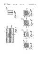
- FIG. 1is a partial longitudinal sectional view of two adjacently positioned blood vessels having a blood flow passageway formed therebetween, and a connector apparatus of the present invention implanted within such blood flow passageway to facilitate and maintain the desired side-to-side connection between the blood vessels.
- FIG. 2is a perspective view of a coil-type connector apparatus of the present invention.
- FIG. 2 ′is a perspective view of a modified coil-type connector apparatus of the present invention.
- FIG. 2 ′′is a perspective view of another modified coil-type connector apparatus of the present invention having a tubular mid portion.
- FIG. 2 ′′′is a perspective view of another coil-type connector apparatus of the present invention having a fused mid-portion.
- FIG. 2 ′′′′is a side elevtional view of a helical coil connector apparatus of the present invention which is biased to a longitudinally collapsed configuration.
- FIG. 3is a perspective view of a mesh type connector apparatus of the present invention.
- FIG. 3 ′is a perspective view of a mesh type connector apparatus of the present invention having optional engagement members formed on either end thereof.
- FIG. 3 ′′is a perspective view of the mesh type connector apparatus of FIG. 3 ′ wherein the engagement members are self-splaying.
- FIG. 3 ′′′is a perspective view of the mesh type connector apparatus of FIG. 3 ′ wherein the engagement members are pressure-splayable, and wherein the apparatus is shown in conjunction with a pressure-exerting balloon catheter which is useable to splay the engagement members at the desired implantation site.
- FIG. 4is a perspective view of a tube type connector apparatus of the present invention.
- FIG. 4 ′is a perspective view of a tube type connector apparatus of the present invention having optional engagement members formed on either end thereof.
- FIG. 4 ′′is a perspective view of the tube type connector apparatus shown in FIG. 4 ′, wherein the engagement members are self-splaying.
- FIG. 4 ′′′is a perspective view of the tube type connector apparatus shown in FIG. 4 ′, wherein the engagement members are pressure-splayable, and wherein the apparatus is shown in conjunction with a pressure-exerting balloon catheter which is useable to cause splaying of the engagement members at the desired implantation site.
- FIG. 5is a perspective view of a cylindrical connector apparatus of the present invention comprising a solid (non-perforated) tube member having optional engagement members formed on either end thereof.
- FIG. 5 ′is a perspective view of a non-hyperbolic, cylindrical connector apparatus wherein the engagement members are self-splaying.
- FIG. 5 ′′is a perspective view of a cylindrical connector apparatus wherein engagement members are pressure-splayable, and wherein the apparatus is shown in conjunction with a pressure-exerting balloon-catheter which is usable to cause splaying of the engagement members at the desired implantation site.
- FIG. 5 ′′′is a perspective view of a cylindrical connector apparatus wherein the tube member is formed of wire mesh having a multiplicity of openings or perforations formed therein, and multiple engagement members are formed on both ends of the tube member;
- FIG. 5 ′′′′is a perspective view of a cylindrical connector apparatus wherein the tube member is formed of wire mesh having a multiplicity of openings or perforations formed therein, and two (2) engagement members are formed on each end of the tube member, said engagement members being in direct alignment with one another;
- FIG. 5 ′′′′′is a perspective view of a cylindrical connector apparatus wherein the tube member is formed of a solid tube, and wherein engagement members comprising semi-circular wire projections are mounted on either end of the tube member;
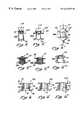
- FIG. 6is a perspective view of a two-piece rivet-type connector apparatus of the present invention having a first rib-in-groove connection system formed thereon.
- FIG. 6 ′is a perspective view of an alternative two-piece rivet-type connector apparatus of the present invention having a tapered friction-fit engagement system formed thereon.
- FIG. 6 ′′is a perspective view of another alternative two-piece rivet-type connector apparatus of the present invention having a second rib-in-groove or magnetic type engagement system formed thereon.
- FIG. 7 ais a top plan view of a first elastomeric connector apparatus of the present invention comprising a tubular mid-portion having elastomeric engagement members formed at either end thereof.
- FIG. 7 a ′is a perspective view of the elastomeric connector apparatus of FIG. 7 a.
- FIG. 7 bis a top plan view of another elastomeric connector apparatus of the present invention comprising a tubular mid portion having a non-circular lumen and engagement flanges formed at either end thereof.
- FIG. 7 b ′is a perspective view of the connector apparatus shown in FIG. 7 b.
- FIG. 7 cis a perspective view of a connector apparatus of the present invention comprising an elastomeric body having wire support members formed therein.
- FIG. 7 dis a perspective view of a wire connector apparatus of the present invention.
- FIG. 7 d ′is a perspective view of the wire connector apparatus of FIG. 7 d having a cylindrical elastomeric or fabric sleeve formed thereon.
- FIG. 7 d ′′is a perspective view of another wire connector apparatus formed of two of the connector apparatus of FIG. 7 d , coupled together to form a singular apparatus.
- FIG. 8is a perspective view of a sinusoidal wire connector apparatus of the present invention in a flattened configuration, prior to fabrication into its desired final configuration.
- FIG. 8 ais a perspective view of the sinusoidal wire connector apparatus of FIG. 8 following fabrication of into its desired final configuration, and showing the apparatus in a preferred implantation position forming a connection between adjacent tubular anatomical conduits.
- FIG. 9is a perspective view of a triplet coil type connector apparatus of the present invention, showing the apparatus in a preferred implantation position forming a connection between adjacent tubular anatomical conduits.
- FIG. 10is a longitudinal sectional view of a flanged tube connector of the present invention in a preferred implantation position forming a connection between adjacent tubular anatomical conduits.
- FIG. 10 ais a perspective view of a segment of tubing which has been precut for fabrication into the flanged tubular connector apparatus of FIG. 10 .
- FIG. 10 bis a side elevational view of the pre-notched segment of tubing shown in FIG. 10 a.
- FIG. 11 ais a perspective view of a first embodiment of a flanged roll-up connector apparatus of the present invention.
- FIG. 11 bis a perspective view of a second embodiment of a flanged roll-up connector apparatus of the present invention.
- FIG. 11 cis a perspective view of a flanged cylindrical connector apparatus of the present invention.
- FIG. 12is a perspective view showing the manner in which any of the connector apparatus of the present invention may be modified to form a non-perpendicular connection between adjacent anatomical structures.
- FIG. 13is a perspective view of a segment of myocardium showing an alternative application of the connector apparatus of the present invention to form a connection between a coronary blood vessel and a chamber of the heart.
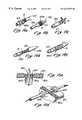
- FIG. 14 ais a schematic showing of a retractable sheath type delivery catheter useable to deliver connector apparatus of the present invention.
- FIG. 14 bis a schematic showing of an inflatable balloon type delivery catheter useable to deliver connector apparatus of the present invention.
- FIG. 14 cis a schematic showing of a push rod type delivery catheter useable to deliver connector apparatus of the present invention.
- FIG. 14 dis a schematic showing of an alter-apposing slider sheath type delivery catheter useable to deliver connector apparatus of the present invention.
- FIG. 14 eis a schematic showing of a rotatable delivery catheter useable to deliver and implant connector apparatus of the present invention.
- FIG. 15 ais a showing of a two-piece connector apparatus as described and claimed in parent application Ser. No. 08/730,327, modified to illustrate the manner in which the connecting portion of the connector apparatus may protrude through tissue and lay outside of the passageway which has been formed between the adjacent anatomical structures.
- FIG. 15 a ′is an exploded view of the connector apparatus shown in FIG. 15 a.
- Non-thrombogenic or antithrombogenicwhen used in blood-contacting applications and/or anti-infective or anti-microbial and/or radioactive so as to deter neointimal growth or natural closure or narrowing of the passageway.
- the portions of the connector apparatus which abut against or engage the luminal or inner wall of each anatomical structuremay be shaped to conform to that luminal or inner wall (e.g., engagement members of flanges may be hemi-cylindrically bowed or cupped to conform to the wall of a blood vessel to which connection is made.
- the connector apparatusmay be structured or designed to maintain a desired cross-sectional dimension or diameter of the openings formed in the adjacent anatomical structures and any interstitial passageway formed between such openings;
- the connector apparatusmay preferably be formed of a continuous or single structural element having minimal likelihood of breakage or dismemberment after implantation.
- a flow control element or valuee.g., a one-way check valve
- a specific pattern or type of flowe.g., unidirectional flow
- connection portion of the connector apparatusmay be adapted to form passageways of various shapes (eg., cylindrical, ovoid, arcuate).
- the connector apparatusmay be constructed with varying amounts of structural support or scaffolding, or may incorporate intraluminally placed structural or non-structural elements which will retard or restrain neointimal growth or natural closure or narrowing of the passageway.
- the connector apparatuswill preferably be capable of withstanding all forces (e.g., hemodynamic pressures, muscular contractions or other forces created by movement or impact of the body) which will be encountered following implantation, without resultant adverse effect (e.g., breakage, dislodgement, slippage, movement or other untoward affect on the connector apparatus).
- forcese.g., hemodynamic pressures, muscular contractions or other forces created by movement or impact of the body
- adverse effecte.g., breakage, dislodgement, slippage, movement or other untoward affect on the connector apparatus.
- the connector apparatusmay be constructed and configured so as to apply residual forces to compress or otherwise minimize the length of the passageway between the first and second anatomical structures following implantation.
- the connector apparatusmay be adapted to receive and transmit energy supplied through the delivery apparatus (e.g., delivery catheter). Such energy may serve to modify the surrounding tissue which defines the openings in the first and second anatomical structures as well as any passageway created between interstitial tissue which resides between the anatomical structures.
- energysupplied through the delivery apparatus (e.g., delivery catheter). Such energy may serve to modify the surrounding tissue which defines the openings in the first and second anatomical structures as well as any passageway created between interstitial tissue which resides between the anatomical structures.
- the connector apparatusmay be configured to control or define the geometric shape of the passageway so as to maximize flow performance and/or to minimize adverse flow conditions such as turbulence.
- the connector apparatusmay be constructed to support rotational twisting and torsion without adverse effects.
- FIG. 1provides a general showing of the manner in which the connector apparatus 10 of the present invention is implanted or installed within openings formed in adjacent blood vessels BV 1 , BV 2 to maintain side-by-side connection and direct alignment of the side wall openings formed in the blood vessel BV 1 , BV 2 .
- the blood vessels BV 1 , BV 2may be endogenous arteries and/or veins in their natural anatomical positions, or may constitute one endogenous artery or vein having a synthetic or biological tube graft placed in juxtaposition thereto.
- FIGS. 2 - 2 ′′′show several variations of a first embodiment 10 a of the connector apparatus of the present invention.
- Each of the variants shown in FIGS. 2 - 2 ′′′comprise a helical coil formed of resilient or superelastic wire 12 , such coil having opposite ends of a first diameter D 1 and a mid-portion of a second diameter D 2 .
- the second diameter D 2 of the mid-portion of the coilis smaller than the first diameter D 1 of the ends, such that the apparatus 10 a is generally of all hyperbolic or “hourglass” shape.
- the coilis of a cylindrical or frusto-conical shape and is provided with additional engagement members which extend laterally outward from the opposite ends of the coil.
- the wire 12 of which the apparatus, 10 a is formedis sufficiently resilient or superelastic in the range of temperatures in which the apparatus 10 a is used (i.e., at room temperature and body temperature) to allow the apparatus 10 a to be initially radially compressed (and concurrently longitudinally elongated) into a relatively small diameter, compact configuration which may be inserted into the lumen of a delivery catheter.
- the delivery catheteris then advanced through the desired anatomical passageway (e.g., blood vessel BV 1 or BV 2 such that an opening of the catheter is located within the region between the side wall openings in the adjacent anatomical conduits or blood vessels BV 1 , or BV 2 .
- the apparatus 10 ais expelled out of the catheter and permitted to resiliently or elastically reassume its hyperbolic or hourglass configuration, such that the ends of the first diameter D 1 will engage the walls of each anatomical conduit or blood vessels BV 1 , BV 2 and the mid-portion diameter D 2 will reside within the space or tissue tunnel created between the side wall of openings in the adjacent anatomical conduits or blood vessels BV 1 , BV 2 .
- the entire apparatus 10 ais formed of a tightly wound helical wire coil such that each adjacent convolution of the wire 12 is in close juxtaposition or abutment to the adjacent convolution thereof.
- Thisprovides a hyperbolic coil of substantially continuous construction, as shown in FIG. 2 .
- FIG. 2 ′shows a variant of the first embodiment of the connector apparatus 10 a wherein the resilient or superelastic wire 12 is tightly wound at either end such that multiple adjacent convolutions of the wire are closely spaced or in direct abutment at either end of the apparatus 10 a ′, while the mid-portion of the apparatus D 2 comprises a more loosely wound traversing segment 14 comprising a single strand of the wire 12 which extends from the abutting convolutions at one end of the apparatus 10 a ′ to the abutting convolutions at the other end of the apparatus 10 a′.
- the apparatus 10 a ′′comprises tightly wound helical wire coil segments of generally spiral or frusto-conical configuration located at either end, with a tubular sleeve 16 forming the mid portion of the apparatus 10 a ′′.
- This tubular sleeve 16may be formed of tubular plastic material such as polytetrafluoroethylene (PTFE), expanded polytetrafluoroethylene (EPTFE) polyethylene (PE), silicone, polyurethane (PU), or polyester.
- PTFEpolytetrafluoroethylene
- EPTFEexpanded polytetrafluoroethylene
- PEpolyethylene
- siliconepolyurethane
- polyesterpolyurethane
- the tubular sleeve 16may be formed of natural, autologus or xenograft material.
- the spiral or frusto-conical wire coil segments located at either end of the apparatus 10 a ′′may comprise the opposite ends of a continuous wire coil which extends through the lumen of the tubular sleeve 16 , or may comprise two separate, non-continuous coil segments each of which is affixed or mounted to one end of the tubular sleeve 16 .
- the variant of the connector apparatus 10 a ′′′ shown in FIG. 2 ′′′comprises a continuous, tightly wound helical coil of resilient or superelastic wire 12 which is similar in configuration to that shown in FIG. 2, but wherein two or more adjacent convolutions of the wire 12 at the mid-portion of the apparatus 10 a ′′′ have been welded, adhered or otherwise fused to one another to form a continuous, tubular mid-portion of diameter D 2 .
- Such fusion of the adjacent convolutions of wire 12 forming the mid-portion of the apparatus 10 a ′′′may comprise weldments 18 , or adhesive or any other suitable fusion material capable of welding adhering or otherwise fusing the adjacent convolutions of wire 12 to one another.
- FIG. 2 ′′′′shows an example of this concept, as applied to the helical coil connector of FIG. 2 .
- the helical coil connector 10 a ′′′′when in its relaxed state, has a longitudinally compact configuration wherein the first and second ends of the coil are close-spaced.
- the force exerted by the coilis preferably not to great as to cause undesirable tissue necrosis or undesirable proliferation of tissues which are longitudinally compressed or constrained by this embodiment of the apparatus 10 a ′′′′. It will be further appreciated that the biasing of the connector apparatus 10 a ′′′′ to such longitudinally compact configuration will enable the connector apparatus 10 a ′′′′ to be used in channels or passageways of varying length, thereby eliminating the need for providing manufacturing and stocking a variety of such connector apparatus 10 a ′′′′ having differing lengths.
- FIGS. 3 - 3 ′′′show several variants of tubular mesh connector apparatus lob having inwardly arched (e.g., hyperboloidal side walls.)
- FIG. 3shows a basic hyperbolic mesh connector apparatus 10 b which comprises a tube formed of wire mesh having an inwardly arched, hyperboloidal or “hourglass” configuration.
- the wire mesh connectorsmay alternatively be of cylindrical or frusto-conical configuration with additional engagement members or projections extending laterally outward from the opposite ends of such cylindrical or frusto-conical mesh tube.
- This embodiment of the connector apparatus 10 bhas distal ends of a first diameter D 1 and a second diameter D 2 .
- the diameter D 2 of the mid-portionis smaller than the diameters D 1 of the ends, thereby providing the desired hyperbolic or hourglass configuration.
- the mesh structure of the apparatus 10 bis preferably formed of a multiplicity of wire segments 18 which are interwoven into the desired mesh structure.
- the wire segments 18may be formed of a resilient or superelastic wire material so as to render the apparatus 10 b radially compressible (and concurably longitudinally elongatable) to a reduced diameter capable of being positioned within a delivery catheter, and to subsequently allow the apparatus 10 b to resiliently self-expand to its desired hyperbolic or hourglass configuration of diameters D 1 and D 2 after having been expelled from the constraining catheter or other delivery device.
- the hyperbolic or hourglass configuration of the apparatus 10 bwill be such that the end portions of diameter D 1 will engage the walls of the adjacent anatomical passageways or blood vessels BV 1 , BV 2 , so as to hold the apparatus 10 b in the desired position between the anatomical passageways or blood vessels BV 1 , BV 2 .
- one or more splayable engagement members 20may be formed on one or both ends of the wire mesh tube to facilitate engagement of the opposite ends of the apparatus 10 b to the walls of the connected anatomical passageways or blood vessels BV 1 , BV 2 .
- FIG. 3 ′shows a variant of the apparatus 10 b ′ having wire loop type engagement members 20 formed on both ends thereof.
- the wire loop type engagement members 20will be deployed in extended positions such that they extend longitudinally from either end of the wire mesh tube and are parallel or close to parallel to the longitudinal axis LA of the apparatus 10 b ′.
- These engagement members 20may be formed of resilient or spring material so as to be self splaying (FIG. 3 ′′) or may be formed of bendable or malleable material so as to be pressure-splayable (FIG. 3 ′′′).
- the resilient or self-splayable engagement members 20will, when released from the surrounding constraint of the delivery catheter, self-splay (i.e., curve outwardly) to their desired engagement positions wherein such engagement members 20 may be generally perpendicular or near perpendicular to the longitudinal axis LA of the device 10 b′′.
- the apparatus 10 b ′′′will be initially positioned within the adjacent openings formed in the first and second anatomical passageways or blood vessels BV 1 , BV 2 such that the engagement members 20 formed on one end of the apparatus 10 b ′′′ protrude or extend into the lumen of the first anatomical passageway or blood vessel BV 1 and the engagement members 20 on the opposite end of the apparatus 10 b ′′′ protrude or extend into the lumen of the second anatomical passageway or blood vessel BV 2 .
- a pressure exerting apparatussuch as the dual balloon catheter 24 shown in FIG.
- One type of dual balloon catheter 24 useable for this purposecomprises an elongate pliable catheter 26 having a singular dumbbell-shaped or hour glass shaped balloon or the combination of a first balloon 28 and a second balloon 30 formed at spaced apart location thereon, as shown.
- the first balloon 28 and second balloon 30are spaced apart or separated by a distance which is equal to, or bears a predetermined relationship to, the length of the apparatus 10 b ′′′ such that the first balloon 28 may be positioned within and adjacent the longitudinally extended engagement members 20 on one end of the apparatus 10 b ′′′ and the second balloon 30 may be positioned within and adjacent the longitudinally extended engagement members 20 on the other end of the apparatus 10 b ′′′.
- first and second balloons 28 , 30are inflated causing them to exert pressure against the engagement members 20 on both ends of the apparatus 10 b ′′′, resulting in the desired splaying or bending of the engagement members 20 to their engagement positions wherein they are generally in apposition to, or embedded in, the wall(s) of the anatomical structure on either side of the channel.
- first balloon 28 and second balloon 30are deflated and the catheter 26 is removed, leaving the connector apparatus 10 b ′′′ in its installed and implanted location between the first and second passageways or blood vessels BV 1 , BV 2 .
- FIGS. 4 - 4 ′′′show several variants of a tube connector apparatus 10 c 10 c ′′′ which generally comprises a segment of radially compressible or collapsible resilient tube member 30 having inwardly arched, hyperboloidal or “hourglass” shaped side walls having opposite ends of a first diameter D 1 and a mid-portion of a second diameter D 2 .
- the tubemay alternatively be of cylindrical or frusto-conical shape with additional engagement members which extend laterally outward from either end of the tube, which may not require expansion for placement.
- FIG. 4shows a connector apparatus 10 c which comprises a hyperbolic or hourglass shaped tube member 36 which is positionable within side openings formed in two adjacent anatomical passageways (e.g., blood vessels BV 1 , BV 2 ) such that one end of the tube member 36 having diameter D 1 will engage the luminal surface of one of the passageways or blood vessels BV 1 and the other end of the tube member 36 also of diameter D 1 will engage the luminal surface of the other passageway of blood vessel BV 2 .
- anatomical passagewayse.g., blood vessels BV 1 , BV 2
- the outwardly tapered or enlarged diameters of the ends of the tube membersthus serve to engage the anatomical passageways or blood vessels BV 1 , BV 2 without the need for additional flanges, projections or other engagement members on either end of the tube member 36 .
- FIG. 4 ′shows the hyperbolic tube member 36 of FIG. 4 with optional engagement members 20 formed on both ends thereof.
- These engagement members 20may comprise flanges, tabs, or, as shown, splayable wire loops.
- These engagement members 20are initially disposed such that they extend longitudinally from either end of the hyperbolic tube member 36 and are parallel or close to parallel to the longitudinal axis LA of the tube member 36 .
- the engagement members 20are caused to splay outwardly such that they become perpendicular or close to perpendicular to the longitudinal axis LA of the tube member 36 , as shown in FIGS. 4 ′′ and 4 ′′′.
- the engagement members 20may be formed of resilient, superelastic, shape memory or spring material so as to be self-splayable (FIG. 4 ′′) or may be formed of bendable or plastically deformable material so as to be pressure-splayable (FIG. 4 ′′′).
- a self-splayable embodiment of the apparatus 10 ccomprises engagement members 20 which, when relieved of the surrounding constraint of a delivery catheter or other delivery apparatus, will self-splay to their outwardly deployed positions wherein they are generally perpendicular or close to perpendicular to the longitudinal axis LA of the apparatus 10 c′′.
- FIG. 4 ′′′there is shown an embodiment of the apparatus 10 c ′′′ wherein the engagement members 20 are pressure-splayable.
- This embodiment of the apparatus 10 c ′′′is initially positioned such that the engagement members 20 on one end of the apparatus 10 c ′′′ extend into the lumen of one anatomical passageway or blood vessel BV 1 , and the engagement members 20 on the other end of the apparatus 10 c ′′′ extend into the lumen of the second anatomical passageway or blood vessel BV 2 .
- a pressure exerting apparatussuch as the above-described balloon catheter 26 having first and second balloons 28 , 30 , is then utilized to exert pressure upon the engagement members 20 to cause the engagement members to move from their longitudinally extended positions (FIG.
- FIGS. 5 - 5 ′show several variants of a cylindrical connector apparatus 10 b of the present invention.
- This cylindrical connector apparatus 10 bgenerally comprises a cylindrical, tubular mid-portion 38 of substantially constant diameter, in combination with one or more engagement members formed on either end thereof.
- the engagement members 20may comprise splayable wire loops as shown in the drawings, or any other suitable type of flange, lip, tab or other member capable of abutting against the luminal wall of an anatomical passageway or blood vessel BV 1 , BV 2 to prevent longitudinal slippage or movement of the tubular mid-portion in at least one direction. In this manner, the formation and deployment of such engagement member on either end of the tubular mid-portion 38 will anchor and hold the tubular mid-portion 38 in its desired implantation position between the openings formed in the adjacent passageways of blood vessels BV 1 and BV 2 .
- the tubular mid-portion 38 of the apparatus 10 dmay comprise a tube of resilient plastic, woven dacron or any other suitable material which is collapsible to a small diameter so as to be initially packed within the lumen of a delivery catheter, and which is subsequently radially expandable or unfoldable to a desired diameter D such that blood or other bodily fluid may flow through the cylindrical tubular member 38 from one anatomical passageway or blood vessel BV 1 into another anatomical passageway or blood vessel BV 2 .
- tubular mid-portion 38may be a rigid or semi-rigid tube formed of metal, carbon or alloy which is generally not radially expandable, but which is provided with additional engagement members which may be splayed or extended from opposite ends of the tubular mid-portion 38 to engage or embed within the adjacent tissue of the anatomical structure.
- rigid or semi-rigid tubular mid-portions 38may be of any suitable shaped configuration, including cylindrical, frusto-conical or hyperbolic (e.g., hourglass) shape.
- the engagement members 20are preferably initially disposed in positions wherein they are longitudinally extended from either end of the cylindrical tubular mid-portion 38 generally parallel or close to parallel to the longitudinal axis LA of the apparatus 10 d as shown in FIG. 5 .
- the engagement members 20may be formed of resilient, superelastic, shape memory or spring material so as to be self-splayable (FIG. 5) or may be formed of bendable or plastically deformable material so as to be pressure-splayable (FIG. 5 ′′) With reference to FIG.
- a self-splayable embodiment of apparatus 10 dcomprises engagement members 20 which, when relieved of the surrounding constraint of the delivery catheter or other delivery apparatus, will self-splay to their outwardly deployed position wherein they are generally perpendicular or close to perpendicular to the longitudinal axis LA of the apparatus 10 b′.
- FIG. 5 ′′in embodiments of the apparatus 10 b ′′ wherein the engagement members 20 are pressure-splayable.
- This embodiment of the apparatus 10 b ′′is initially positioned such that the engagement members 20 on one end of the apparatus 10 b ′′ extend into the lumen of one anatomical passageway or blood vessel BV 1 and the engagement members 20 on the other end of the apparatus 10 b ′′ extend into the lumen of the second anatomical passageway or blood vessel BV 2 .
- a pressure exerting apparatussuch as the above-described balloon catheter 26 having first and second balloons 28 , 30 , is then utilized to exert pressure upon the engagement members 20 to cause the engagement members to move from their longitudinally extended positions (FIG.
- FIGS. 6 - 6 ′′show several variants of rivet type connector apparatus which comprise a first tubular member 40 having a first engagement flange 44 formed thereon and a second tubular member 42 having a second engagement flange 46 formed thereon.
- the first and second tubular members 40 , 42are connectible to one another such the lumens of the tubular members 40 , 42 are in direct alignment thereby forming a singular lumen 41 through the center of the apparatus 10 e , 10 e ′, 10 e′′.
- FIGS. 6, 6 ′ and 6 ′′Various snap-fitting or frictional engagement systems may be utilized to securely connect the first and second tubular members 40 , 42 to one another, and examples of such snap-fitting or frictional engagement systems are shown in the showings of FIGS. 6, 6 ′ and 6 ′′.
- annular groove 48in the outer surface of the first tubular member 40 and a corresponding raised ridge 50 in the outer surface of the second tubular member 42 .
- the raised ridge 50is sized and configured to snap fit and seat within the groove 48 as the first tubular member 40 is advanced into the interior of the second tubular member 42 .
- the respective engagements 44 , 46will be held in fixed spaced-apart relation to one another such that the distance between flanges 44 , 46 will result in engagement of the flanges with the respective luminal walls of the anatomical passageways or blood vessels BV 1 , BV 2 which are intended to be connected by the apparatus 10 e.
- FIG. 6 ′shows another connector apparatus 10 e comprising a first tubular member 40 ′ and a second tubular member 42 ′.
- Engagement flanges 44 ′, 46 ′are formed about the outer ends of the first and second tubular members 40 ′, 42 ′, respectively.
- the outer surface of the first tubular member 40is tapered inwardly toward the non-flanged end such that, as it is advanced into the interior of the second tubular member 42 ′, the outer surface of the first tubular member 40 ′ will tighten against and frictionally engage the inner surface of the second tubular member 42 ′, thereby holding the first and second tubular members 40 ′, 42 ′ in fixed, connected relation to one another such that the engagement flanges, 44 ′, 46 ′ are held in spaced-apart relation such that the distance there between will cause the flanges 44 ′, 46 ′ to be in abutting contact with the respective luminal surfaces of the first and second passageways or blood vessels BV 1 , BV 2 .
- FIGS. 7 a - 7 d ′show examples of connector apparatus 10 h , 10 i of the present invention formed of elastomeric materials such as a resilient elastomeric polymer (e.g., polyurethane, silicone, etc.).
- a resilient elastomeric polymere.g., polyurethane, silicone, etc.
- FIGS. 7 a , 7 a ′show an embodiment of a connector apparatus 10 h comprising an elastomeric, cylindrical tube 60 having a hollow lumen 62 extending longitudinally therethrough and four engagement members in the nature of tabs formed on opposite ends of the tube 60 and extending outwardly therefrom in directions which are substantially perpendicular to the longitudinal axis LA of the tube 60 .
- FIGS. 7 b , 7 b ′show another embodiment of a connector apparatus 10 i which comprises an ovoid tube member 70 formed of elastomeric material and substantially rectangular engagement members 74 in the nature of flanges formed on either end thereof.
- the engagement members 74extend in directions which are parallel to the length-wise axis of the ovoid lumen 72 of the ovoid tube member 70 , as shown.
- the ovoid tube member 70 having the ovoid lumen 72 , and the corresponding configuration and directional orientation of the engagement members 74will enable this embodiment of the connector apparatus 10 i to be utilized in blood vessels or anatomical passageways of relatively small diameter, with openings which are elongate or ovoid so as to permit a greater amount of body fluid to flow through the openings than would be possible than if the openings were of a circular configuration.
- any circular opening formed in the side wall of a passageway or blood vessel BV 1 , BV 2cannot exceed the diameter of the passageway or blood vessel BV 1 , BV 2
- elongate or ovoid openingsmay have a width which is equal to or slightly less than the diameter of the passageway or blood vessel BV 1 , BV 2 and a length which is larger than the diameter of such passageway or blood vessel BV 1 , BV 2 .
- This tube member 70may also incorporate any suitable reinforcing material, such as wire.
- This ovoid or non-circular configuration of the tube member 70 and its lumen 72may be incorporated into any of the embodiments of the invention described herein, and is not necessarily limited to the particular elastomeric embodiment shown in FIGS. 7 b , 7 b′.
- the material of which the apparatus 10 h , 10 i is formedis sufficiently resilient and compressible to be initially packed into the lumen of a delivery catheter, and is sufficiently resilient such that when the apparatus 10 h , 10 i is expelled or otherwise passed out of the delivery catheter, the absence of restraint upon the apparatus 10 h , 10 i will allow the apparatus to assume its fully expanded and operative configuration as shown in the figures.
- the abutment members 64 or 74When in such fully expanded and operative configuration, the abutment members 64 or 74 will abut against the lumenal surfaces of the passageways or blood vessels BV 1 , BV 2 , in the regions immediately surrounding the openings formed therein, and the tube members 60 , 70 of the apparatus 10 h , 10 i will extend between the respective passageways or blood vessels BV 1 , BV 2 , thereby forming a conduit or passageway between the openings formed in the passageways or blood vessels BV 1 , BV 2 .
- FIGS. 7 c - 7 d ′show examples of wire connector members with optional coverings formed thereon. These coverings may cover all or any portion of the apparatus. For example, such covering may be formed on the connecting portion or mid-portion of the apparatus so as to form a sleeve or covering which lines the passageway, while the engagement portions (e.g., extendable engagement members) of the apparatus may remain devoid of such covering.
- Such coveringsmay be formed of any suitable material including, but not limited to, elastomeric material, fabrics (e.g., woven polyester) or natural materials such as autologus or xenograft material.
- FIG. 7 cthere are provided two separate generally U-shaped wire members 80 which are partially embedded with an elastomeric tube member 82 having a hollow lumen 84 extending longitudinally therethrough.
- the portions of the wire members 80 which protrude out of the elastomeric tube member 82may also be covered with elastomeric material 86 .
- the portions of the wire members 80(with or without elastomeric covering 86 ) which protrude outwardly from the elastomeric tube member 82 may serve to abut against and engage the luminal surfaces of the passageways or blood vessels BV 1 , BV 2 , such that body fluid may pass through the lumen 84 of the tube member 82 , from one passageway or blood vessel BV 1 to the other passageway or blood vessel BV 2 .
- FIGS. 7 d - 7 d ′shows another embodiment of a connector apparatus 10 k which comprises a continuous segment of wire which is formed into a configuration having four generally U-shaped projections 92 extending laterally outward therefrom in opposite directions.
- This apparatus 10 kmay be utilized as a connector apparatus in and of itself, without any elastomeric covering, such that the U-shaped projection 92 may be placed in abutment with the luminal surfaces of the adjacent passageways or blood vessels BV 1 , BV 2 , thereby clipping or holding the openings formed in the passageways or blood vessels BV 1 , BV 2 in alignment with one another, and establishing the desired interconnection of the passageways or blood vessels BV 1 , BV 2 .
- FIG. 7 d ′shows an optional elastomeric tube member 94 having the central portion of the wire member formed therein such that the U-shaped projections 92 extend laterally outboard and away from the elastomeric tube member 94 .
- the elastomeric tube memberis provided with a hollow lumen 96 extending longitudinally therefrom and, when the U-shaped projections are in abutment with the luminal surfaces of the passageways of blood vessels BV 1 , BV 2 , the elastomeric tube member 94 will form a discrete conduit or passageway whereby body fluid may pass through the lumen 96 of the tube member 94 from one passageway or blood vessel BV 1 to the other passageway or blood vessel BV 2 .
- FIGS. 8-8 ashow a connector apparatus 101 which is formed of a wire member 100 which has been formed or bent into multiple sinusoidal waves or convolutions, some of such sinusoidal waves or convolutions being of a first size 102 and others of such sinusoidal waves or convolutions being of a second size 104 .
- the smaller sinusoidal waves or convolutions 102are formed in pairs or couplets, with the larger sinusoidal waves or convolutions 104 being also formed in pairs or couplets which are positioned alternately with the pairs or couplets of the smaller sinusoidal waves or convolutions 102 .
- the smaller sinusoidal waves or convolutions 102will define a hollow passageway 106 and the larger sinusoidal waves or convolutions 104 may be bent laterally outward from the center of the passageway 106 so as to abut against and engage the respective luminal surfaces of the anatomical passageways or blood vessels BV 1 , BV 2 , as shown in FIG. 8 a .
- the sinusoidal wire connector apparatus 101as shown in FIGS.
- 8 aserves to hold the first and second blood vessels BV 1 , BV 2 in connection with one another such that side wall openings formed in such first and second blood vessels BV 1 and BV 2 will be maintained in direct alignment with one another, thereby allowing body fluid to pass through the passageway 106 of the connector apparatus 101 from the lumen of one blood vessel BV 1 to the lumen of the other blood vessel BV 2 .
- a covering formed of any suitable materialmay be formed on all or part of the device.
- a tubular coveringmay be mounted on the mid-portion formed by the smaller sinusoidal waves or convolutions 102 and the basal portions of the larger sinusoidal waves or convolutions 104 , and such cover may optionally may extend outwardly over the entireties of the laterally bent portions of the larger sinusoidal waves or convolutions 104 , in accordance with the invention as described hereabove in relation to FIGS. 7 c and 7 d′.
- FIG. 9shows a triplet coil type connector apparatus 10 m of the present invention comprising a first coil portion 114 a , a second coil portion 114 b and a third coil portion 114 c .
- the apparatus 10 mis formed of a continuous wire member 110 which has been helically wound to form a coil wherein adjacent convolutions of the coil are in direct abutment with one another, or are closely spaced to one another.
- the first coil segment 114 ahas a first longitudinal axis LA 1 .
- the coil segment 114 bhas a second longitudinal axis LA 2 which may be perpendicular to the first longitudinal axis LA 1 of the first coil segment 114 a .
- the third coil segment 114 chas a third longitudinal axis LA 3 which may be parallel to the first longitudinal axis LA 1 of the first coil segment 114 a and perpendicular to the second longitudinal axis LA 2 of the first coil segment 114 b.
- the length 1 of the second coil segment 114 bmay vary depending upon the desired distance between the first and second passageways or blood vessels BV 1 , BV 2 .
- the wire member 110may be formed of any suitable material such as stainless steel, superelastic nickel titanium alloy, etc.
- the apparatus 10 mis preferably sufficiently pliable and resilient such that the three coil segments 114 a , 114 b , 114 c may be disposed in direct alignment with one another about a common longitudinal axis and radially compressed (and concurrently elongated) so as to be positionable within the lumen of a delivery catheter.
- the delivery cathetermay be advanced through the second blood vessel BV 2 , through the opening formed between the second blood vessel BV 2 and first blood vessel BV 1 , and into the lumen of the first blood vessel BV 1 .
- the third coil segment 114 cwill be expelled out of the delivery catheter and allowed to assume its radially expanded, operative configuration as shown in FIG. 9 .
- the delivery catheterwill be retracted to a position within or adjacent the opening between the first blood vessel BV 1 and second blood vessel BV 2 , and the second coil segment 114 b will be expelled or advanced out of the delivery catheter and allowed to radially expand to its expanded, operative configuration and attitude about the second longitudinal axis LA 2 as shown in FIG. 9 .
- the delivery catheteris further retracted into the lumen of the second blood vessel BV 2 and the first coil segment 114 a is expelled or advanced out of the delivery catheter and allowed to expand to its expanded, operative configuration as shown in FIG. 9 .
- first and third coil segments 114 a , 114 cwill seat against and frictionally engage the luminal surfaces of the first and second blood vessels BV 1 and BV 2 , respectively, and the second coil segment 114 b will traverse any space which exists between the first and second blood vessels BV 1 and BV 2 .
- a tubular covering or enclosuremay be formed upon the inner and/or outer surfaces of any and/or all of the coil members 114 a , 114 b , 114 c to provide a flow conduit which is impermeable to fluid, or to enhance the biocompatibility of the apparatus 10 m.
- FIGS. 10-10 bshow a flanged tube type connector apparatus 10 n of the present invention. It will be appreciated that, in addition to the specific flang configurations shown in the drawings, such flanges may be formed in many different configurations and designs and/or may include notches, geometries and configurational attributes designed to enhance the ability of the connector apparatus to withstand longitudinal contractions/expansions and rotational/orientation motions of the surrounding tissue.
- the embodiment 10 n shown in FIG. 10comprises a segment of tubing which has been notched and formed such that semi-cylindrical or arcuate flanges 120 extend laterally outward from opposite sides of either end of a cylindrical or tubular mid-portion 122 .
- the semi-cylindrical or arcuate flangesWhen implanted between two blood vessels, as illustrated in FIG. 10, the semi-cylindrical or arcuate flanges will abut against the luminal surfaces of the blood vessels and will approximate the semi-cylindrical or arcuate shape of the adjacent luminal blood vessel surface.
- the tubular or cylindrical mid-portion 22forms a discrete tubular conduit which extends between the opening formed in the adjacent blood vessels, thereby providing a substantially fluid tight conduit through which blood or other bodily fluid may pass.
- FIGS. 10-10 billustrate a preferred method of manufacturing this flanged tube type connector apparatus 10 n .
- a segment of cylindrical tubing formed of resilient metal, resilient plastic, shape memory alloy or other suitable materialis precut such that two (2) longitudinal notches 124 (e.g., rectangular notches) are formed in each end of the tube, at locations directly opposite one another, as shown.
- two transverse notches 126e.g., arcuate or wedge shaped notches
- the center of each such transverse notch 126is approximately 90° from the centers of the adjacent longitudinal notches 124 formed on that end of the tube.
- the protruding end portions of the notched tubeare deformed or bent outwardly, as indicated by the arrows on FIG. 10 a .
- FIGS. 11 a - 11 cshow three embodiments of externally ribbed cylindrical connectors 10 o , 10 p , 10 q of the present invention.
- the connector 10 o shown in FIG. 11 acomprises a cylindrical or tubular body 130 formed of a rolled sheet of resilient metal or plastic having overlapping ends 132 such that the rolled cylindrical body may be radially compressed to a radially compact diameter, and will subsequently resiliently return to a radially expanded diameter as shown in FIG. 11 a .
- Cylindrical flanges or ribs 134are formed about either end of the rolled tube 130 , as shown. In this manner, the apparatus 10 o may be held in its radially compact state within an introducer or catheter and delivered into a passageway formed between two anatomical structures, where it is allowed to radially expand to its operative configuration.
- Such radial expansionwill cause the flange 134 at one end of the rolled cylindrical body 130 to abut against and engage the luminal surface of a first blood vessel or anatomical structure, surrounding a first opening formed in that blood vessel or anatomical structure.
- the flange or rib 134 b at the opposite end of the rolled tubular body 130will abut against and engage the luminal surface surrounding an opening formed in a second blood vessel or other anatomical structure.
- FIG. 11 bshows another ribbed connector apparatus 10 p which also comprises a rolled cylindrical body portion 136 formed and configured the same as that shown in FIG. 11 a .
- this apparatus 10 pa plurality of annular flanges or ribs 138 are formed about the outer surface of the rolled cylindrical body 136 .
- the flanges or ribs 138 on the outer surface of the rolled cylindrical bodywill embed into or engage interstitial tissue which surrounds the cylindrical body 136 , thereby holding the apparatus 10 p in its desired position between openings formed in adjacent blood vessels or anatomical structures.
- this embodiment of the apparatus 10 pwill be particularly useful in applications wherein firm interstitial tissue surrounds the passageway which extends between the openings formed in the adjacent blood vessels or anatomical structures.
- this apparatus 10 pis devoid of any flanges or projections or surfaces which will abut against or engage the luminal surfaces of the adjacent blood vessels or anatomical structure, and relies instead on the engagement of the ribs or flanges 138 with the interstitial tissue to prevent the apparatus 10 p from dislodging or longitudinally moving following implantation.
- FIG. 11 cshows another example of a ribbed cylindrical connector apparatus 10 g comprising a continuous cylindrical tubular body 140 having a helical rib or flange 142 formed about the outer surface thereof.
- the continuous cylindrical body 140differs from the rolled cylindrical bodies of the embodiments 10 o , 10 p shown in FIGS. 11 a and 11 b in that it does not have overlapping ends and can not be radially compressed in a “roll-up” state. Rather, the cylindrical body 140 of this apparatus 10 g is of a continuous cylindrical structure and is formed of resilient or collapsible material that will enable the apparatus 10 g to be placed in a radially compact or reduced state for delivery into a passageway formed between openings and adjacent blood vessels or anatomical structures.
- this apparatus 10 gwill be particularly useable in applications wherein the passageway formed between the blood vessels or other anatomical structures has firm surrounding interstitial tissue into which the helical rib or flange 142 may imbed.
- FIGS. 12 and 13are intended to show modifications and alternative applications which may be applicable to all of the connector apparatus shown in FIGS. 1-11.
- FIG. 12is illustrative of the concept of forming the ends of each connector apparatus 10 such that the ends are non-perpendicular to the longitudinal axis LA of the apparatus 10 .
- Such angle-cutting of the ends of the connector apparatus 10will be applicable when the connector apparatus 10 is to be disposed within a diagonal or curved passway formed between openings which are not directly opposite one another on adjacent anatomical structures or blood vessels BV 1 , BV 2 .
- This aspect of the inventionwill be particular applicable in certain arterial bypass procedures, such as those described in U.S. patent application Ser. Nos. 08/730,327 and 08/730,496, when it is desired to form curved or diagonal blood flow passageways to minimize turbulence and to promote substantially laminar blood flow through the passageway and into the bypass vessel.
- FIG. 13shows a connector apparatus 10 , which has the configuration of the specific apparatus 10 k shown in FIG. 7 d , disposed within a transmyocardial passageway formed between a coronary blood vessel CBV and the left ventricle LV of the heart.
- FIG. 13serves as an example of an application wherein any or all of the connector apparatus 10 of the present invention may be used to form a connection between anatomical structures other than two blood vessels (i.e., a coronary blood vessel and a chamber of the heart).
- the length or distance between the first and second anatomical structuresmay vary considerably.
- many if not all of the embodiments of the present inventionmay be constructed such that the connecting portion of the connector apparatus 10 is elastic, adjustable, telescoping, distendable, of according configuration, or otherwise adjustable to accommodate or conform to passageways of differing length.
- the connectormay be delivered via any number or possible delivery mechanisms including but not limited to:
- Delivery mechanismswhich trap the connector initially within an inner tubular member and an outer tubular member wherein movement of the one member relative to the other allows the connector to be exposed and deployed at first partially to allow the first set of engagement members to come in contact with the first lumen and then deployed fully to allow the second set of engagement members to come into contact with the second lumen.
- Connectorswhich are mounted onto a balloon, covered or non-covered by a temporary sheath, and then deployed with the assistance or forcibly directed by the balloon to their engaging position.
- Two piece connectorssuch as the rivet device shown in FIG. 6, may be deployable via two members mounted over a central core capable of moving towards each other such that the resultant force acts to engage the inner aspect of the two rivet components, fixing them in apposition.
- Delivery mechanismswhich hold the connector in a compressed state within a sheath and deploy the connector through the relative movement of an inner push-rod mechanism, allowing it to deploy in a first partially expanded state, and then to a fully expanded state.
- connectorswhich may be rotationally inserted into the tissue, expanding it as it is advanced into position, and then disengaged, allowing the connector to remain anchored within the channel that was partially enhanced by the delivery mechanism.
- Delivery mechanismswhich utilize some form of thermal, electrical, fluid or chemical means to induce a conformational change in the connector upon proper positioning in the channel.
- FIGS. 14 a - 14 dExamples of suitable delivery catheters for implanting connector apparatus 10 of the present invention are shown in FIGS. 14 a - 14 d.
- FIG. 14 ashows a withdrawable sheath type delivery catheter 100 a comprising an elongate inner member 102 having a connector apparatus 10 of the present invention mounted thereon, and a surrounding retractable outer sheath 104 .
- the connector apparatus 10 in this embodimentis preferably self-expanding or formed of shape memory material which will radially expand when warmed to body temperature. When the sheath 104 is fully advanced over the connector apparatus 10 , the sheath will radially constrain and hold the connector apparatus 10 in the desired radially compact configuration.
- the sheath 104may then be retracted (or alternatively the inner member 102 may be advanced) thereby removing the surrounding constraint from the connector apparatus 10 such that the connector apparatus 10 may radially expand and become implanted in the desired location.
- FIG. 14 bshows a balloon delivery catheter 100 b comprising a tubular catheter body 106 and an elongate member 108 having an inflatable balloon 110 formed thereon.
- the connector apparatus 10is initially mounted on the deflated balloon 110 with the connector apparatus 10 in its radially compact configuration.
- the catheter 106is withdrawn (or the inner member 108 is advanced) and the balloon in inflated so as to radially expand the connector apparatus 10 and to cause the connector apparatus to become implanted at its desired implantation site.
- FIG. 14 cshows a push rod type delivery catheter 100 c comprising an outer tubular sheath 112 an advanceable push rod 114 .
- the connector apparatus 10is initially placed in the lumen of the catheter sheath 112 , ahead of the distal end of the push rod 114 , with the connector apparatus 10 in its radially compact configuration.
- the catheter 112may be retracted (or the push rod 114 may be advanced) to expel the connector apparatus 10 out of the distal end of the catheter.
- the connector apparatus 10is relieved of any surrounding constraint and is permitted to radially expand and become implanted in the desired implantation site.
- FIG. 14 dshows a slider sheath type delivery 100 d .
- This devicecomprises an inner member 120 upon which the connector apparatus 10 is mounted in its radially compact configuration.
- Proximal and distal sheaths 122 a 122 bare initially drawn together such that the distal end of the proximal sheath member 122 a is in abutment with the proximal end of the distal sheath member 122 b , thereby covering and providing an enclosure or constraint about the radially collapsed connector apparatus 10 .
- proximal and distal sheath member 122 a , 122 bis/are moved away from the other so as to expose the radially compact connector apparatus 10 , as shown in FIG. 14 b .
- the connector apparatus 10is self-expanding or formed of shape memory material which will expand upon warming to body temperature, such opening of the slider sheaths 122 a , 122 b will allow the connector apparatus 10 to expand and become implanted at its desired implantation site.
- the radial expansion membersuch as an inflatable balloon will be mounted on the inner member 120 beneath the radially compact connector apparatus 10 .
- Such radial expansion or balloonmay then be radially expanded (e.g., inflated) to radially expand and plastically deform the connector apparatus 10 , as desired.
- FIG. 14 eshows a rotatable delivery catheter 100 e which comprises an elongate member 130 which is in itself rotatable, or which is provided with a rotatable distal portion.
- the connector apparatus 10is mounted upon the distal portion of the elongate member 130 , as shown. After the elongate member 130 has been advanced to a position adjacent the desired implantation site, the elongate member 130 or the distal portion thereof is rotated, and the elongate member 130 is further advanced so as to rotatably drive and advance the connector apparatus 10 into the desired implantation site.
- this embodimentis particularly useable for connector apparatus 10 which are not radially expandable, and or those having helical or spiral ribs on the outer surface thereof (e.g., FIG. 11 c ) and/or for those having a leading edge which is sharpened or otherwise adapted to cut tissue so as to bore and form or enlarge the passageway as the connector apparatus is advanced.
- FIGS. 14 a - 14 eare examples of the types of delivery catheter devices which may be utilized, in addition to the double balloon catheter shown in FIGS. 3 ′′′, 4 ′′′ and 5 ′′, and described more fully hereabove.
- FIGS. 15 a - 15 a ′show a modified rivet type connector apparatus 10 e ′′′, of the type previously described and claimed in U.S. patent application Ser. No. 08/730,327.
- This connector apparatus 10 e ′′′comprises first and second annular engagement members 600 , 602 , and a plurality of connecting members 604 which extend from first engagement member 600 and which are adapted to engage and connect to receiving aperture 606 formed in the second engagement member 602 . As shown in FIGS.
- the connector member 604may be capable of penetrating through the tissue, and may be situated such that they will pass through the walls of the first and second blood vessels BV 1 , BV 2 and through any intervening interstitial tissue such that the connector members 604 will lay outside of the previously formed passageway or channel, and outside of the openings formed in the respective first and second blood vessels BV 1 , BV 2 .
- connector portion of the connector apparatus 10need not extend through or reside within the fluid flow passageway, but actually may protrude through intervening tissue and reside outboard of the passageway, as shown.
- These delivery devicesare generally capable of being advanced over a guide wire into the channel and may assist passively or actively in the proper deployment of the connector. Further it should be understood that various radiopaque or imageable markers may be placed in important locations on the delivery mechanism to permit proper placement or monitoring of placement during deployment. Further, it is also possible that various recapturing mechanisms such as thread(s), hood(s) or other capturing or securing means may be provided to allow for the reversible deployment of the connector in the instance where it was found to be improperly placed.
Landscapes
- Health & Medical Sciences (AREA)
- Life Sciences & Earth Sciences (AREA)
- Engineering & Computer Science (AREA)
- Biomedical Technology (AREA)
- Surgery (AREA)
- Veterinary Medicine (AREA)
- Heart & Thoracic Surgery (AREA)
- Animal Behavior & Ethology (AREA)
- General Health & Medical Sciences (AREA)
- Public Health (AREA)
- Medical Informatics (AREA)
- Molecular Biology (AREA)
- Nuclear Medicine, Radiotherapy & Molecular Imaging (AREA)
- Cardiology (AREA)
- Transplantation (AREA)
- Physics & Mathematics (AREA)
- Vascular Medicine (AREA)
- Oral & Maxillofacial Surgery (AREA)
- Plasma & Fusion (AREA)
- Otolaryngology (AREA)
- Biophysics (AREA)
- Optics & Photonics (AREA)
- Pathology (AREA)
- Radiology & Medical Imaging (AREA)
- Media Introduction/Drainage Providing Device (AREA)
- Surgical Instruments (AREA)
- Prostheses (AREA)
- Infusion, Injection, And Reservoir Apparatuses (AREA)
Abstract
Description
Claims (91)
Priority Applications (3)
| Application Number | Priority Date | Filing Date | Title |
|---|---|---|---|
| US09/117,520US6616675B1 (en) | 1996-02-02 | 1997-01-31 | Methods and apparatus for connecting openings formed in adjacent blood vessels or other anatomical structures |
| US09/860,147US6709444B1 (en) | 1996-02-02 | 2001-05-17 | Methods for bypassing total or near-total obstructions in arteries or other anatomical conduits |
| US10/370,231US7179270B2 (en) | 1995-10-13 | 2003-02-19 | Methods for bypassing total or near-total obstructions in arteries or other anatomical conduits |
Applications Claiming Priority (5)
| Application Number | Priority Date | Filing Date | Title |
|---|---|---|---|
| US1061496P | 1996-02-02 | 1996-02-02 | |
| US08/730,327US6190353B1 (en) | 1995-10-13 | 1996-10-11 | Methods and apparatus for bypassing arterial obstructions and/or performing other transvascular procedures |
| US08/730,496US5830222A (en) | 1995-10-13 | 1996-10-11 | Device, system and method for intersititial transvascular intervention |
| US09/117,520US6616675B1 (en) | 1996-02-02 | 1997-01-31 | Methods and apparatus for connecting openings formed in adjacent blood vessels or other anatomical structures |
| PCT/US1997/001468WO1997027898A1 (en) | 1996-02-02 | 1997-01-31 | Methods and apparatus for connecting openings formed in adjacent blood vessels or other anatomical structures |
Related Parent Applications (1)
| Application Number | Title | Priority Date | Filing Date |
|---|---|---|---|
| US08/730,496Continuation-In-PartUS5830222A (en) | 1995-10-13 | 1996-10-11 | Device, system and method for intersititial transvascular intervention |
Publications (1)
| Publication Number | Publication Date |
|---|---|
| US6616675B1true US6616675B1 (en) | 2003-09-09 |
Family
ID=43805687
Family Applications (1)
| Application Number | Title | Priority Date | Filing Date |
|---|---|---|---|
| US09/117,520Expired - LifetimeUS6616675B1 (en) | 1995-10-13 | 1997-01-31 | Methods and apparatus for connecting openings formed in adjacent blood vessels or other anatomical structures |
Country Status (8)
| Country | Link |
|---|---|
| US (1) | US6616675B1 (en) |
| EP (1) | EP0932426A4 (en) |
| JP (1) | JP2000505316A (en) |
| CN (1) | CN1218414A (en) |
| AU (1) | AU723785B2 (en) |
| CA (2) | CA2244080A1 (en) |
| IL (1) | IL125416A0 (en) |
| WO (1) | WO1997027898A1 (en) |
Cited By (326)
| Publication number | Priority date | Publication date | Assignee | Title |
|---|---|---|---|---|
| US20010001827A1 (en)* | 1998-03-09 | 2001-05-24 | Chapman Troy J. | Anastomosis device and method |
| US20020183769A1 (en)* | 2001-05-30 | 2002-12-05 | St. Jude Medical Atg, Inc. | Medical grafting methods and apparatus |
| US20030014062A1 (en)* | 1996-11-08 | 2003-01-16 | Houser Russell A. | Percutaneous bypass graft and securing system |
| US20030032967A1 (en)* | 2001-06-20 | 2003-02-13 | Park Medical, Llc | Anastomotic device |
| US20030055371A1 (en)* | 1998-01-30 | 2003-03-20 | Percardia, Inc. | Left ventricular conduits to coronary arteries and methods for coronary bypass |
| US20030088256A1 (en)* | 2001-10-03 | 2003-05-08 | Conston Stanley R. | Devices and methods for interconnecting vessels |
| US20030100920A1 (en)* | 1999-07-28 | 2003-05-29 | Akin Jodi J. | Devices and methods for interconnecting conduits and closing openings in tissue |
| US20030120292A1 (en)* | 2001-06-20 | 2003-06-26 | Park Medical, Llc | Anastomotic device |
| US20030130671A1 (en)* | 1999-11-23 | 2003-07-10 | Duhaylongsod Francis G. | Anastomosis device and method |
| US20030153933A1 (en)* | 1998-01-23 | 2003-08-14 | Bolduc Lee R. | System for performing vascular anastomoses |
| US20040024289A1 (en)* | 2002-04-29 | 2004-02-05 | Hugh Trout | Method and apparatus for supporting a surgical component |
| US6719781B1 (en)* | 1996-06-14 | 2004-04-13 | Aptus Medical Inc. | Catheter apparatus having an improved shape-memory alloy cuff and inflatable on-demand balloon for creating a bypass graft in-vivo |
| US20040078053A1 (en)* | 1998-01-30 | 2004-04-22 | St. Jude Medical Atg, Inc. | Medical graft connector or plug structures, and methods of making and installing same |
| US20040092858A1 (en)* | 2002-08-28 | 2004-05-13 | Heart Leaflet Technologies, Inc. | Leaflet valve |
| US20040116945A1 (en)* | 2000-04-29 | 2004-06-17 | Ventrica, Inc., A Delaware Corporation | Components, systems and methods for forming anastomoses using magnetism or other coupling means |
| US20040172050A1 (en)* | 1995-02-24 | 2004-09-02 | Bolduc Lee R. | Surgical clips and methods for tissue approximation |
| WO2003088820A3 (en)* | 2002-04-19 | 2004-12-29 | Broncus Tech Inc | Devices for maintaining surgically created openings |
| US20050043785A1 (en)* | 1997-06-30 | 2005-02-24 | Howard Tanner | Surgical fastener for use during a surgical procedure |
| US20050043751A1 (en)* | 2001-09-04 | 2005-02-24 | Broncus Technologies, Inc. | Methods and devices for maintaining patency of surgically created channels in a body organ |
| US20050049675A1 (en)* | 2003-03-28 | 2005-03-03 | Board Of Regents, The University Of Texas System | Medical devices and related methods |
| US20050070939A1 (en)* | 2003-09-30 | 2005-03-31 | Jean Beaupre | Unfolding anastomosis ring device |
| US6899718B2 (en) | 1995-02-24 | 2005-05-31 | Heartport, Inc. | Devices and methods for performing avascular anastomosis |
| US20050131525A1 (en)* | 2003-10-10 | 2005-06-16 | William A. Cook Australia Pty. Ltd. | Ring stent |
| EP1547526A1 (en)* | 2003-12-23 | 2005-06-29 | UMC Utrecht Holding B.V. | Operation element, operation set and method for use thereof |
| US20050143763A1 (en)* | 2003-12-29 | 2005-06-30 | Ortiz Mark S. | Device and method for intralumenal anastomosis |
| US6913021B2 (en) | 1996-08-13 | 2005-07-05 | Percardia, Inc. | Method for revascularizing a coronary vessel |
| US20050149166A1 (en)* | 2003-11-08 | 2005-07-07 | Schaeffer Darin G. | Branch vessel prosthesis with anchoring device and method |
| US6916304B2 (en) | 1999-05-04 | 2005-07-12 | Percardia, Inc. | Transmyocardial implant with flow reduction |
| US20050165426A1 (en)* | 2002-06-19 | 2005-07-28 | Scott Manzo | Method and apparatus for anastomosis including annular joining member |
| US6926690B2 (en) | 1998-09-10 | 2005-08-09 | Percardia, Inc. | Transmyocardial shunt and its attachment mechanism, for left ventricular revascularization |
| US6941950B2 (en)* | 2001-10-11 | 2005-09-13 | Emphasys Medical, Inc. | Bronchial flow control devices and methods of use |
| US6949118B2 (en) | 2002-01-16 | 2005-09-27 | Percardia, Inc. | Encased implant and methods |
| US20050222669A1 (en)* | 2004-03-31 | 2005-10-06 | Purdy James D | Fenestrated intraluminal stent system |
| US6953481B2 (en) | 1998-09-10 | 2005-10-11 | Percardia, Inc. | Designs for left ventricular conduit |
| US20050243343A1 (en)* | 2004-04-30 | 2005-11-03 | Nexpress Solutions Llc | PMS color expansion with fifth color |
| US6964652B2 (en) | 1999-08-04 | 2005-11-15 | Percardia, Inc. | Left ventricular conduits and methods for delivery |
| US6966917B1 (en) | 2000-11-09 | 2005-11-22 | Innovation Interventional Technologies B.V. | Deformable connector for mechanically connecting hollow structures |
| US20050278013A1 (en)* | 2004-05-26 | 2005-12-15 | Matthew Rust | Method for endovascular bypass stent graft delivery |
| US6976990B2 (en) | 2001-01-25 | 2005-12-20 | Percardia, Inc. | Intravascular ventriculocoronary bypass via a septal passageway |
| US20050283188A1 (en)* | 1998-05-29 | 2005-12-22 | By-Pass, Inc. | Vascular closure device |
| US20060030933A1 (en)* | 2004-08-04 | 2006-02-09 | Delegge Rebecca | Thermal transition methods and devices |
| US20060036282A1 (en)* | 2001-06-01 | 2006-02-16 | Velocimed Pfo, Inc. | Closure devices, related delivery methods and tools, and related methods of use |
| US20060047337A1 (en)* | 2004-08-27 | 2006-03-02 | Brenneman Rodney A | Device and method for establishing an artificial arterio-venous fistula |
| US7008397B2 (en) | 2002-02-13 | 2006-03-07 | Percardia, Inc. | Cardiac implant and methods |
| US7011095B2 (en) | 1998-09-10 | 2006-03-14 | Percardia, Inc. | Valve designs for left ventricular conduits |
| US7018387B2 (en) | 1998-10-22 | 2006-03-28 | Innovative Interventional Technologies B.V. | Mechanical anastomosis system for hollow structures |
| US7022127B2 (en) | 1997-10-24 | 2006-04-04 | Innovative Interventional Technologies Bv | Mechanical anastomosis system for hollow structures |
| US7033372B1 (en) | 1999-08-04 | 2006-04-25 | Percardia, Inc. | Corkscrew reinforced left ventricle to coronary artery channel |
| US20060095058A1 (en)* | 2004-10-13 | 2006-05-04 | Protech Medical Technologies Ltd. | Prostate treatment stent |
| US20060111704A1 (en)* | 2004-11-22 | 2006-05-25 | Rox Medical, Inc. | Devices, systems, and methods for energy assisted arterio-venous fistula creation |
| US20060112956A1 (en)* | 2002-11-06 | 2006-06-01 | Michel Serpelloni | Use of branched malto-dextrins as granulation binders |
| US20060129083A1 (en)* | 2004-12-15 | 2006-06-15 | Rox Medical, Inc. | Method of treating COPD with artificial arterio-venous fistula and flow mediating systems |
| US20060135947A1 (en)* | 2000-10-27 | 2006-06-22 | Pulmonx | Occlusal stent and methods for its use |
| US20060167543A1 (en)* | 1999-12-31 | 2006-07-27 | Bailey Steven R | Endoluminal cardiac and venous valve prostheses and methods of manufacture and delivery thereof |
| US20060206123A1 (en)* | 2004-08-27 | 2006-09-14 | Rox Medical, Inc. | Device and method for establishing an artificial arterio-venous fistula |
| US20060212049A1 (en)* | 2005-03-16 | 2006-09-21 | Mohiuddin Mohammed M | Pyeloplasty clip |
| US7122044B2 (en) | 1994-06-17 | 2006-10-17 | Heartport, Inc. | Surgical stapling instrument and method thereof |
| US20070010834A1 (en)* | 2000-04-29 | 2007-01-11 | Sharkawy A A | Components, systems and methods for forming anastomoses using magnetism or other coupling means |
| US20070016250A1 (en)* | 2003-04-11 | 2007-01-18 | St. Jude Medical, Cardiology Division, Inc. | Closure devices, related delivery methods, and related methods of use |
| WO2007014283A2 (en) | 2005-07-26 | 2007-02-01 | Rox Medical, Inc. | Devices, systems, and methods for peripheral arteriovenous fistula creation |
| US20070191872A1 (en)* | 2003-04-24 | 2007-08-16 | Medtronic Vascular, Inc. | Membrane eyelet |
| US20070249985A1 (en)* | 2004-08-27 | 2007-10-25 | Rox Medical, Inc. | Device and method for establishing an artificial arterio-venous fistula |
| US7318833B2 (en)* | 2001-12-19 | 2008-01-15 | Nmt Medical, Inc. | PFO closure device with flexible thrombogenic joint and improved dislodgement resistance |
| US7326219B2 (en) | 2002-09-09 | 2008-02-05 | Wilk Patent Development | Device for placing transmyocardial implant |
| US7351247B2 (en) | 2002-09-04 | 2008-04-01 | Bioconnect Systems, Inc. | Devices and methods for interconnecting body conduits |
| US20080215071A1 (en)* | 2004-02-26 | 2008-09-04 | Zimmermann Hanngorg | Implantable Prosthesis for Repairing Hernia Defects |
| US7422563B2 (en) | 1999-08-05 | 2008-09-09 | Broncus Technologies, Inc. | Multifunctional tip catheter for applying energy to tissue and detecting the presence of blood flow |
| US20080243067A1 (en)* | 2007-03-29 | 2008-10-02 | Dan Rottenberg | Lumen reentry devices and methods |
| US7431727B2 (en) | 2000-04-29 | 2008-10-07 | Medtronic, Inc. | Magnetic components for use in forming anastomoses, creating ports in vessels and closing openings in tissue |
| US7455677B2 (en)* | 2002-01-22 | 2008-11-25 | Cardica, Inc. | Anastomosis device having a deployable section |
| US7462162B2 (en) | 2001-09-04 | 2008-12-09 | Broncus Technologies, Inc. | Antiproliferative devices for maintaining patency of surgically created channels in a body organ |
| WO2007140559A3 (en)* | 2006-06-06 | 2008-12-11 | Filho Luiz Gonzaga Granja | Prosthesis for anastomosis |
| US20080312684A1 (en)* | 2007-02-05 | 2008-12-18 | Boston Scientific Scimed, Inc | Apparatus and Method for Closing an Opening in a Blood Vessel Using a Permanent Implant |
| US20090018555A1 (en)* | 2005-03-18 | 2009-01-15 | Castlewood Surgical, Inc. | System and method for attaching a vein, an artery, or a tube in a vascular environment |
| US20090054974A1 (en)* | 2001-11-14 | 2009-02-26 | Rex Medical | Percutaneous aortic valve |
| US20090093837A1 (en)* | 2007-10-09 | 2009-04-09 | Wilson-Cook Medical Inc. | Anastomosis plug for bariatric surgery |
| US20090093825A1 (en)* | 2007-08-21 | 2009-04-09 | Castlewood Surgical, Inc. | System and Method for Providing a Coil Element in a Vascular Environment |
| US20090143760A1 (en)* | 2007-11-30 | 2009-06-04 | Jacques Van Dam | Methods, Devices, Kits and Systems for Defunctionalizing the Gallbladder |
| US7585306B2 (en) | 2003-12-24 | 2009-09-08 | Maquet Cardiovascular Llc | Anastomosis device, tools and methods of using |
| US20090254105A1 (en)* | 2008-04-04 | 2009-10-08 | Medtronic Vascular, Inc. | Anastomotic connectors |
| US20090259298A1 (en)* | 2008-04-11 | 2009-10-15 | Kevin Mayberry | Bifurcated graft deployment systems and methods |
| US20100023132A1 (en)* | 2008-07-28 | 2010-01-28 | Incube Laboratories LLC | System and method for scaffolding anastomoses |
| WO2010024867A1 (en)* | 2008-08-27 | 2010-03-04 | Cleveland Clinic Foundation | Stent graft fixation coupling |
| US20100087842A1 (en)* | 2002-04-16 | 2010-04-08 | Tyco Healthcare Group Lp | Methods and Apparatus for Anastomosis Including an Expandable Anchor |
| US7704222B2 (en) | 1998-09-10 | 2010-04-27 | Jenavalve Technology, Inc. | Methods and conduits for flowing blood from a heart chamber to a blood vessel |
| US20100130994A1 (en)* | 2007-04-16 | 2010-05-27 | Corlife Gbr | Vessel connector and kit having an applicatior for surgery |
| US20100268319A1 (en)* | 2009-04-17 | 2010-10-21 | Medtronic Vascular, Inc. | Mobile External Coupling for Branch Vessel Connection |
| US20100268327A1 (en)* | 2009-04-17 | 2010-10-21 | Medtronic Vascular, Inc. | Mobile External Coupling for Branch Vessel Connection |
| US20100268316A1 (en)* | 2004-08-27 | 2010-10-21 | Rox Medical, Inc. | Device and method for establishing an artificial arterio-venous fistula |
| WO2010129162A1 (en)* | 2009-05-06 | 2010-11-11 | Hansa Medical Products, Inc. | Self-adjusting medical device |
| US20100318109A1 (en)* | 2006-06-06 | 2010-12-16 | Luiz Gonzaga Granja Filho | Prosthesis for anastomosis |
| WO2011009122A1 (en)* | 2009-07-17 | 2011-01-20 | Correx, Inc. | Method and apparatus for suturelessly connecting a conduit to a hollow organ |
| US20110054381A1 (en)* | 2009-05-29 | 2011-03-03 | Jacques Van Dam | Biliary shunts, delivery systems, and methods of using the same |
| US7909837B2 (en) | 2000-12-13 | 2011-03-22 | Medtronic, Inc. | Methods, devices and systems for forming magnetic anastomoses |
| US7918870B2 (en) | 2005-09-12 | 2011-04-05 | Bridgepoint Medical, Inc. | Endovascular devices and methods |
| US7938819B2 (en) | 2005-09-12 | 2011-05-10 | Bridgepoint Medical, Inc. | Endovascular devices and methods |
| US20110118765A1 (en)* | 2009-11-18 | 2011-05-19 | Aguirre Andres F | Anastomosis stent |
| US20110130624A1 (en)* | 2009-12-02 | 2011-06-02 | Hamman Baron L | System and method for attaching a vessel in a vascular environment |
| US20110153009A1 (en)* | 2003-05-20 | 2011-06-23 | The Cleveland Clinic Foundation | Apparatus and methods for repair of a cardiac valve |
| US20110152886A1 (en)* | 2007-02-26 | 2011-06-23 | Olympus Medical Systems Corp. | Applicator and tissue fastening method through natural orifice |
| EP2194887A4 (en)* | 2007-10-04 | 2011-08-17 | Xlumena Inc | DEVICES AND METHODS FOR ANCHORING LUMINUM STRUCTURE |
| US8034100B2 (en) | 1999-03-11 | 2011-10-11 | Endologix, Inc. | Graft deployment system |
| US20110251452A1 (en)* | 2010-04-09 | 2011-10-13 | Davinci Biomedical Research Products Inc. | Stoma stabilitating device and method |
| US20110276067A1 (en)* | 2002-06-20 | 2011-11-10 | Tyco Healthcare Group Lp | Method and Apparatus for Anastomosis Including Annular Joining Member |
| US8083727B2 (en) | 2005-09-12 | 2011-12-27 | Bridgepoint Medical, Inc. | Endovascular devices and methods for exploiting intramural space |
| US20120010589A1 (en)* | 2007-01-30 | 2012-01-12 | Boston Scientific Scimed, Inc. | Local delivery of therapeutic agent to heart valves |
| US8118856B2 (en) | 2009-07-27 | 2012-02-21 | Endologix, Inc. | Stent graft |
| US8162963B2 (en) | 2004-06-17 | 2012-04-24 | Maquet Cardiovascular Llc | Angled anastomosis device, tools and method of using |
| US8167925B2 (en) | 1999-03-11 | 2012-05-01 | Endologix, Inc. | Single puncture bifurcation graft deployment system |
| US8172863B2 (en) | 2008-04-28 | 2012-05-08 | Bridgepoint Medical, Inc. | Methods and apparatus for crossing occlusions in blood vessels |
| US20120123453A1 (en)* | 2010-11-11 | 2012-05-17 | Dr. Wilson T. Asfora | Sutureless vascular anastomosis connection |
| US8202246B2 (en) | 2008-02-05 | 2012-06-19 | Bridgepoint Medical, Inc. | Crossing occlusions in blood vessels |
| US8308760B2 (en)* | 2004-05-06 | 2012-11-13 | W.L. Gore & Associates, Inc. | Delivery systems and methods for PFO closure device with two anchors |
| US8323261B2 (en) | 2005-09-12 | 2012-12-04 | Bridgepoint Medical, Inc. | Methods of accessing an intramural space |
| US8328837B2 (en) | 2004-12-08 | 2012-12-11 | Xlumena, Inc. | Method and apparatus for performing needle guided interventions |
| US8337425B2 (en) | 2008-02-05 | 2012-12-25 | Bridgepoint Medical, Inc. | Endovascular device with a tissue piercing distal probe and associated methods |
| US8357193B2 (en) | 2009-05-29 | 2013-01-22 | Xlumena, Inc. | Apparatus and method for deploying stent across adjacent tissue layers |
| US8366651B2 (en) | 2007-08-02 | 2013-02-05 | Bioconnect Systems, Inc. | Implantable flow connector |
| US20130035759A1 (en)* | 2011-08-05 | 2013-02-07 | Yossi Gross | Techniques for percutaneous mitral valve replacement and sealing |
| US8372112B2 (en) | 2003-04-11 | 2013-02-12 | St. Jude Medical, Cardiology Division, Inc. | Closure devices, related delivery methods, and related methods of use |
| US8409167B2 (en) | 2004-07-19 | 2013-04-02 | Broncus Medical Inc | Devices for delivering substances through an extra-anatomic opening created in an airway |
| US20130116614A1 (en)* | 2010-01-22 | 2013-05-09 | Medtronic Vascular, Inc. | Methods and Apparatus for Providing an Arteriovenous Fistula |
| US8454632B2 (en) | 2008-05-12 | 2013-06-04 | Xlumena, Inc. | Tissue anchor for securing tissue layers |
| US8475492B2 (en) | 2009-02-20 | 2013-07-02 | Sapheon, Inc. | Methods for venous occlusion for the treatment of venous insufficiency |
| US8491646B2 (en) | 2009-07-15 | 2013-07-23 | Endologix, Inc. | Stent graft |
| US8518062B2 (en) | 2000-04-29 | 2013-08-27 | Medtronic, Inc. | Devices and methods for forming magnetic anastomoses between vessels |
| US8523931B2 (en) | 2007-01-12 | 2013-09-03 | Endologix, Inc. | Dual concentric guidewire and methods of bifurcated graft deployment |
| EP2649957A1 (en)* | 2012-04-11 | 2013-10-16 | Covidien LP | Apparatus and method for removing occlusive tissue |
| US20130317593A1 (en)* | 2000-03-27 | 2013-11-28 | Neovasc Medical Ltd. | Varying diameter vascular implant and balloon |
| US8632556B2 (en) | 2007-10-22 | 2014-01-21 | Bridgepoint Medical, Inc. | Methods and devices for crossing chronic total occlusions |
| US8663301B2 (en) | 2007-12-11 | 2014-03-04 | Cornell University | Method and apparatus for restricting flow through an opening in the side wall of a body lumen, and/or for reinforcing a weakness in the side wall of a body lumen, while still maintaining substantially normal flow through the body lumen |
| US20140107771A1 (en)* | 2002-04-02 | 2014-04-17 | Daidalos Solutions B.V. | Assembly comprising a stabiliser and an instrument to be positioned in or around a passage surrounded by body tissue |
| US20140114266A1 (en)* | 2012-10-22 | 2014-04-24 | Ams Research Corporation | Ostomy Implant System and Method |
| US8709034B2 (en) | 2011-05-13 | 2014-04-29 | Broncus Medical Inc. | Methods and devices for diagnosing, monitoring, or treating medical conditions through an opening through an airway wall |
| US8728155B2 (en) | 2011-03-21 | 2014-05-20 | Cephea Valve Technologies, Inc. | Disk-based valve apparatus and method for the treatment of valve dysfunction |
| US8728141B2 (en) | 2007-12-11 | 2014-05-20 | Cornell University | Method and apparatus for sealing an opening in the side wall of a body lumen, and/or for reinforcing a weakness in the side wall of a body lumen, while maintaining substantially normal flow through the body lumen |
| US8781604B2 (en) | 2004-08-18 | 2014-07-15 | Cardiac Pacemakers, Inc. | Method of implanting stimulation lead with biased curved section through the interatrial septum |
| US8777967B2 (en) | 2005-06-09 | 2014-07-15 | Xlumena, Inc. | Methods and devices for anchoring to tissue |
| US8784437B2 (en) | 2005-06-09 | 2014-07-22 | Xlumena, Inc. | Methods and devices for endosonography-guided fundoplexy |
| US8808350B2 (en) | 2011-03-01 | 2014-08-19 | Endologix, Inc. | Catheter system and methods of using same |
| US8845614B2 (en) | 2009-02-20 | 2014-09-30 | Sapheon, Inc. | Enhanced ultrasound visualization of intravascular devices |
| US20140303657A1 (en)* | 2011-11-01 | 2014-10-09 | The Asan Foundation | Vascular anastomosis device using a self-expandable material or body, and anastomosis method for blood vessels using same |
| US8870948B1 (en) | 2013-07-17 | 2014-10-28 | Cephea Valve Technologies, Inc. | System and method for cardiac valve repair and replacement |
| US8870950B2 (en) | 2009-12-08 | 2014-10-28 | Mitral Tech Ltd. | Rotation-based anchoring of an implant |
| US8945202B2 (en) | 2009-04-28 | 2015-02-03 | Endologix, Inc. | Fenestrated prosthesis |
| US8951276B2 (en) | 2011-11-04 | 2015-02-10 | Avenu Medical, Inc. | Systems and methods for percutaneous intravascular access and guidewire placement |
| US8956475B2 (en) | 2007-12-11 | 2015-02-17 | Howard Riina | Method and apparatus for restricting flow through an opening in the side wall of a body lumen, and/or for reinforcing a weakness in the side wall of a body lumen, while still maintaining substantially normal flow through the body lumen |
| US8968382B2 (en) | 2007-12-11 | 2015-03-03 | Cornell University | Method and apparatus for restricting flow through an opening in the side wall |
| US8968233B2 (en) | 2012-02-03 | 2015-03-03 | Medtronic Vascular, Inc. | Arteriovenous shunt having a moveable valve |
| US8984733B2 (en) | 2013-02-05 | 2015-03-24 | Artventive Medical Group, Inc. | Bodily lumen occlusion |
| US8992604B2 (en) | 2010-07-21 | 2015-03-31 | Mitraltech Ltd. | Techniques for percutaneous mitral valve replacement and sealing |
| US20150112383A1 (en)* | 2013-10-21 | 2015-04-23 | Cook Medical Technologies Llc | Closure device |
| US9017351B2 (en) | 2010-06-29 | 2015-04-28 | Artventive Medical Group, Inc. | Reducing flow through a tubular structure |
| US9017399B2 (en) | 2010-07-21 | 2015-04-28 | Mitraltech Ltd. | Techniques for percutaneous mitral valve replacement and sealing |
| US9060802B2 (en) | 2006-11-21 | 2015-06-23 | Bridgepoint Medical, Inc. | Endovascular devices and methods for exploiting intramural space |
| US9084835B2 (en) | 2012-02-22 | 2015-07-21 | Covidien Lp | Sterilization process design for a medical adhesive |
| US9095344B2 (en) | 2013-02-05 | 2015-08-04 | Artventive Medical Group, Inc. | Methods and apparatuses for blood vessel occlusion |
| US20150257760A1 (en)* | 2014-03-14 | 2015-09-17 | Cook Medical Technologies Llc | Implant for facilitating sutureless side-to-side arteriovenous fistula creation and maintaining patency |
| US9138230B1 (en) | 2011-04-29 | 2015-09-22 | Avenu Medical, Inc. | Systems and methods for creating arteriovenous (AV) fistulas |
| US9149277B2 (en) | 2010-10-18 | 2015-10-06 | Artventive Medical Group, Inc. | Expandable device delivery |
| US20150313596A1 (en)* | 2014-05-02 | 2015-11-05 | W. L. Gore & Associates, Inc. | Anastomosis Devices |
| US9199067B2 (en) | 2009-01-29 | 2015-12-01 | Tufts Medical Center, Inc. | Endovascular cerebrospinal fluid shunt |
| US9247942B2 (en) | 2010-06-29 | 2016-02-02 | Artventive Medical Group, Inc. | Reversible tubal contraceptive device |
| US20160045199A1 (en)* | 2014-08-14 | 2016-02-18 | W. L. Gore & Associates, Inc. | Anastomosis Devices |
| US9282967B2 (en) | 2007-08-02 | 2016-03-15 | Bioconnect Systems, Inc. | Implantable flow connector |
| US9314600B2 (en) | 2012-04-15 | 2016-04-19 | Bioconnect Systems, Inc. | Delivery system for implantable flow connector |
| US9345532B2 (en) | 2011-05-13 | 2016-05-24 | Broncus Medical Inc. | Methods and devices for ablation of tissue |
| US9358141B2 (en) | 2004-03-31 | 2016-06-07 | Cook Medical Technologies Llc | Stent deployment device |
| US9364259B2 (en) | 2009-04-21 | 2016-06-14 | Xlumena, Inc. | System and method for delivering expanding trocar through a sheath |
| EP1906884B1 (en)* | 2005-07-27 | 2016-06-22 | Medtronic 3F Therapeutics, Inc. | Systems for cardiac valve delivery |
| US9381041B2 (en) | 2009-04-21 | 2016-07-05 | Xlumena, Inc. | Methods and devices for access across adjacent tissue layers |
| US9387311B1 (en) | 2014-10-31 | 2016-07-12 | Cerevasc, Llc | Methods and systems for treating hydrocephalus |
| US9393133B2 (en) | 2011-02-18 | 2016-07-19 | Piolax Medical Devices, Inc. | Abdominal cavity-vein shunt stent |
| US9393100B2 (en) | 2010-11-17 | 2016-07-19 | Endologix, Inc. | Devices and methods to treat vascular dissections |
| US20160220255A1 (en)* | 2007-10-22 | 2016-08-04 | James E. Coleman | Anastomosis Devices and Methods |
| US9439757B2 (en) | 2014-12-09 | 2016-09-13 | Cephea Valve Technologies, Inc. | Replacement cardiac valves and methods of use and manufacture |
| US9439728B2 (en) | 2010-06-15 | 2016-09-13 | Avenu Medical, Inc. | Systems for creating arteriovenous (AV) fistulas |
| US9439710B2 (en) | 2012-11-14 | 2016-09-13 | Avenu Medical, Inc. | Intravascular arterial to venous anastomosis and tissue welding catheter |
| US9452015B2 (en) | 2010-06-15 | 2016-09-27 | Avenu Medical, Inc. | Intravascular arterial to venous anastomosis and tissue welding catheter |
| US20160278780A1 (en)* | 2015-03-27 | 2016-09-29 | Terumo Kabushiki Kaisha | Medical apparatus |
| US9474562B2 (en) | 2012-02-08 | 2016-10-25 | Avenu Medical, Inc. | Intravascular arterial to venous anastomosis and tissue welding catheter |
| US20160374682A1 (en)* | 2014-03-10 | 2016-12-29 | Balatech Limited | Surgical procedure and devices for use therein |
| US9533128B2 (en) | 2003-07-18 | 2017-01-03 | Broncus Medical Inc. | Devices for maintaining patency of surgically created channels in tissue |
| US9545263B2 (en) | 2014-06-19 | 2017-01-17 | Limflow Gmbh | Devices and methods for treating lower extremity vasculature |
| US9554801B2 (en) | 2014-03-14 | 2017-01-31 | Cook Medical Technologies Llc | Extravascular implant for facilitating sutured side-to-side arteriovenous fistula creation and maintaining patency |
| US9561320B2 (en) | 2014-06-05 | 2017-02-07 | Cook Medical Technologies Llc | Device for promoting fistula patency and method |
| US9579103B2 (en) | 2009-05-01 | 2017-02-28 | Endologix, Inc. | Percutaneous method and device to treat dissections |
| WO2017062858A1 (en) | 2015-10-07 | 2017-04-13 | Edwards Lifesciences Corporation | Expandable cardiac shunt and delivery system |
| US9636116B2 (en) | 2013-06-14 | 2017-05-02 | Artventive Medical Group, Inc. | Implantable luminal devices |
| US20170164950A1 (en)* | 2004-09-27 | 2017-06-15 | David W. Wright | Fastener apparatus for tissue and methods of deployment and manufacture |
| US9700701B2 (en) | 2008-07-01 | 2017-07-11 | Endologix, Inc. | Catheter system and methods of using same |
| US9737696B2 (en) | 2014-01-15 | 2017-08-22 | Tufts Medical Center, Inc. | Endovascular cerebrospinal fluid shunt |
| US9737308B2 (en) | 2013-06-14 | 2017-08-22 | Artventive Medical Group, Inc. | Catheter-assisted tumor treatment |
| US9737306B2 (en) | 2013-06-14 | 2017-08-22 | Artventive Medical Group, Inc. | Implantable luminal devices |
| US9763657B2 (en) | 2010-07-21 | 2017-09-19 | Mitraltech Ltd. | Techniques for percutaneous mitral valve replacement and sealing |
| USD800908S1 (en) | 2016-08-10 | 2017-10-24 | Mitraltech Ltd. | Prosthetic valve element |
| USD810941S1 (en) | 2016-10-06 | 2018-02-20 | Edwards Lifesciences Corporation | Cardiac shunt |
| US9974651B2 (en) | 2015-02-05 | 2018-05-22 | Mitral Tech Ltd. | Prosthetic valve with axially-sliding frames |
| US10022252B2 (en) | 2015-06-10 | 2018-07-17 | Cook Medical Technologies Llc | Spiral blood flow device with diameter independent helix angle |
| US10070866B1 (en) | 2013-08-01 | 2018-09-11 | Avenu Medical, Inc. | Percutaneous arterial to venous anastomosis clip application catheter system and methods |
| US10143552B2 (en) | 2015-05-14 | 2018-12-04 | Cephea Valve Technologies, Inc. | Replacement mitral valves |
| US10149968B2 (en) | 2013-06-14 | 2018-12-11 | Artventive Medical Group, Inc. | Catheter-assisted tumor treatment |
| USD836194S1 (en) | 2017-03-21 | 2018-12-18 | Merit Medical Systems, Inc. | Stent deployment device |
| US10159485B2 (en) | 2010-11-11 | 2018-12-25 | Asfora Ip, Llc | Deployment tool for sutureless vascular anastomosis connection |
| USD841812S1 (en) | 2017-08-03 | 2019-02-26 | Cardiovalve Ltd. | Prosthetic heart valve element |
| US10245166B2 (en) | 2008-02-22 | 2019-04-02 | Endologix, Inc. | Apparatus and method of placement of a graft or graft system |
| WO2019067707A1 (en)* | 2017-09-27 | 2019-04-04 | Spiration, Inc. D/B/A Olympus Respiratory America | Tissue fastening tool |
| US10272230B2 (en) | 2015-10-30 | 2019-04-30 | Cerevasc, Llc | Systems and methods for treating hydrocephalus |
| US10272260B2 (en) | 2011-11-23 | 2019-04-30 | Broncus Medical Inc. | Methods and devices for diagnosing, monitoring, or treating medical conditions through an opening through an airway wall |
| US10285834B2 (en) | 2015-03-05 | 2019-05-14 | Merit Medical Systems, Inc. | Vascular prosthesis deployment device and method of use |
| US10363043B2 (en) | 2014-05-01 | 2019-07-30 | Artventive Medical Group, Inc. | Treatment of incompetent vessels |
| US20190231510A1 (en)* | 2017-09-01 | 2019-08-01 | Transmural Systems Llc | Percutaneous shunt devices and related methods |
| US10368990B2 (en) | 2017-01-23 | 2019-08-06 | Cephea Valve Technologies, Inc. | Replacement mitral valves |
| US10376361B2 (en) | 2011-08-05 | 2019-08-13 | Cardiovalve Ltd. | Techniques for percutaneous mitral valve replacement and sealing |
| US10390833B2 (en) | 2008-05-12 | 2019-08-27 | Boston Scientific Scimed, Inc. | Tissue anchor for securing tissue layers |
| US10390952B2 (en) | 2015-02-05 | 2019-08-27 | Cardiovalve Ltd. | Prosthetic valve with flexible tissue anchor portions |
| US10398580B2 (en) | 2004-09-08 | 2019-09-03 | Limflow Gmbh | Minimally invasive surgical apparatus and methods |
| US10420873B2 (en) | 2014-06-06 | 2019-09-24 | Cook Medical Technologies Llc | Device for forming fistula between blood vessels, and method |
| US10434293B2 (en) | 2012-04-15 | 2019-10-08 | Tva Medical, Inc. | Implantable flow connector |
| US20190328556A1 (en)* | 2016-06-13 | 2019-10-31 | Aortica Corporation | Systems, devices, and methods for marking and/or reinforcing fenestrations in prosthetic implants |
| US10470881B2 (en) | 2015-05-14 | 2019-11-12 | Cephea Valve Technologies, Inc. | Replacement mitral valves |
| US10470797B1 (en) | 2018-07-17 | 2019-11-12 | SlipStream, LLC | Systems and methods for vascular access |
| US10492908B2 (en) | 2014-07-30 | 2019-12-03 | Cardiovalve Ltd. | Anchoring of a prosthetic valve |
| US10499919B2 (en) | 2015-08-21 | 2019-12-10 | Avenu Medical, Inc. | Systems and methods for percutaneous access and formation of arteriovenous fistulas |
| US10531866B2 (en) | 2016-02-16 | 2020-01-14 | Cardiovalve Ltd. | Techniques for providing a replacement valve and transseptal communication |
| US10543308B2 (en) | 2017-04-10 | 2020-01-28 | Limflow Gmbh | Methods for routing a guidewire from a first vessel and through a second vessel in lower extremity vasculature |
| US10575948B2 (en) | 2017-08-03 | 2020-03-03 | Cardiovalve Ltd. | Prosthetic heart valve |
| US10631982B2 (en) | 2013-01-24 | 2020-04-28 | Cardiovale Ltd. | Prosthetic valve and upstream support therefor |
| US10744009B2 (en) | 2017-03-15 | 2020-08-18 | Merit Medical Systems, Inc. | Transluminal stents and related methods |
| US10744304B2 (en) | 2009-08-28 | 2020-08-18 | Boston Scientific Limited | Inverted balloon neck on catheter |
| US10772717B2 (en) | 2009-05-01 | 2020-09-15 | Endologix, Inc. | Percutaneous method and device to treat dissections |
| US10772672B2 (en) | 2014-03-06 | 2020-09-15 | Avenu Medical, Inc. | Systems and methods for percutaneous access and formation of arteriovenous fistulas |
| US10799378B2 (en) | 2016-09-29 | 2020-10-13 | Merit Medical Systems, Inc. | Pliant members for receiving and aiding in the deployment of vascular prostheses |
| US10813644B2 (en) | 2016-04-01 | 2020-10-27 | Artventive Medical Group, Inc. | Occlusive implant and delivery system |
| US10849746B2 (en) | 2015-05-14 | 2020-12-01 | Cephea Valve Technologies, Inc. | Cardiac valve delivery devices and systems |
| US10857017B2 (en)* | 2017-07-14 | 2020-12-08 | Bcm Co., Ltd. | Stent insertion device for connecting human digestive organs |
| US10856975B2 (en) | 2016-08-10 | 2020-12-08 | Cardiovalve Ltd. | Prosthetic valve with concentric frames |
| US10864106B2 (en) | 2011-03-08 | 2020-12-15 | W. L. Gore & Associates, Inc. | Medical device for use with a stoma |
| US10888354B2 (en) | 2006-11-21 | 2021-01-12 | Bridgepoint Medical, Inc. | Endovascular devices and methods for exploiting intramural space |
| US10888421B2 (en) | 2017-09-19 | 2021-01-12 | Cardiovalve Ltd. | Prosthetic heart valve with pouch |
| US20210052272A1 (en)* | 2018-02-02 | 2021-02-25 | University Of Louisville Research Foundation, Inc. | Sutureless Graft Anastomotic Quick Connect System |
| US20210059676A1 (en)* | 2019-08-27 | 2021-03-04 | Zhejiang University | Degradable intestinal diversion device |
| US10952732B2 (en) | 2013-02-21 | 2021-03-23 | Boston Scientific Scimed Inc. | Devices and methods for forming an anastomosis |
| US20210121180A1 (en)* | 2019-10-24 | 2021-04-29 | Atrium Medical Corporation | Endovascular fixation device |
| US10993805B2 (en) | 2008-02-26 | 2021-05-04 | Jenavalve Technology, Inc. | Stent for the positioning and anchoring of a valvular prosthesis in an implantation site in the heart of a patient |
| US11000359B2 (en) | 2016-08-02 | 2021-05-11 | Aortica Corporation | Systems, devices, and methods for coupling a prosthetic implant to a fenestrated body |
| US11013900B2 (en) | 2018-03-08 | 2021-05-25 | CereVasc, Inc. | Systems and methods for minimally invasive drug delivery to a subarachnoid space |
| EP3823538A1 (en)* | 2018-07-18 | 2021-05-26 | W.L. Gore & Associates Inc. | Medical devices for shunts, occluders, fenestrations and related systems and methods |
| US11020141B2 (en) | 2005-09-12 | 2021-06-01 | Bridgepoint Medical, Inc. | Endovascular devices and methods |
| US11052608B2 (en) | 2012-05-01 | 2021-07-06 | University Of Washington Through Its Center For Commercialization | Fenestration template for endovascular repair of aortic aneurysms |
| US11065138B2 (en) | 2016-05-13 | 2021-07-20 | Jenavalve Technology, Inc. | Heart valve prosthesis delivery system and method for delivery of heart valve prosthesis with introducer sheath and loading system |
| US11109964B2 (en) | 2010-03-10 | 2021-09-07 | Cardiovalve Ltd. | Axially-shortening prosthetic valve |
| US11116943B2 (en) | 2018-10-09 | 2021-09-14 | Limflow Gmbh | Methods for accessing pedal veins |
| US11129737B2 (en) | 2015-06-30 | 2021-09-28 | Endologix Llc | Locking assembly for coupling guidewire to delivery system |
| US11185405B2 (en) | 2013-08-30 | 2021-11-30 | Jenavalve Technology, Inc. | Radially collapsible frame for a prosthetic valve and method for manufacturing such a frame |
| US11197754B2 (en) | 2017-01-27 | 2021-12-14 | Jenavalve Technology, Inc. | Heart valve mimicry |
| US11207457B2 (en)* | 2004-08-27 | 2021-12-28 | Edwards Lifesciences Corporation | Device and method for establishing an artificial arterio-venous fistula |
| US11207503B2 (en) | 2016-11-11 | 2021-12-28 | Avenu Medical, Inc. | Systems and methods for percutaneous intravascular access and guidewire placement |
| US11246704B2 (en) | 2017-08-03 | 2022-02-15 | Cardiovalve Ltd. | Prosthetic heart valve |
| US11278708B2 (en) | 2014-01-15 | 2022-03-22 | Tufts Medical Center, Inc. | Endovascular cerebrospinal fluid shunt |
| US11291545B2 (en) | 2011-08-05 | 2022-04-05 | Cardiovalve Ltd. | Implant for heart valve |
| US11298511B2 (en) | 2006-11-21 | 2022-04-12 | Bridgepoint Medical, Inc. | Endovascular devices and methods for exploiting intramural space |
| US11304837B2 (en) | 2015-09-15 | 2022-04-19 | Merit Medical Systems, Inc. | Implantable device delivery system |
| US11331187B2 (en) | 2016-06-17 | 2022-05-17 | Cephea Valve Technologies, Inc. | Cardiac valve delivery devices and systems |
| US11337800B2 (en) | 2015-05-01 | 2022-05-24 | Jenavalve Technology, Inc. | Device and method with reduced pacemaker rate in heart valve replacement |
| US11357624B2 (en) | 2007-04-13 | 2022-06-14 | Jenavalve Technology, Inc. | Medical device for treating a heart valve insufficiency |
| US11382747B2 (en) | 2004-02-03 | 2022-07-12 | V-Wave, Ltd. | Device and method for controlling in-vivo pressure |
| US11382714B2 (en)* | 2013-01-18 | 2022-07-12 | The Johns Hopkins University | Ultrasound-detectable markers, ultrasound system, and methods for monitoring vascular flow and patency |
| US11382746B2 (en) | 2017-12-13 | 2022-07-12 | Cardiovalve Ltd. | Prosthetic valve and delivery tool therefor |
| US11406518B2 (en) | 2010-11-02 | 2022-08-09 | Endologix Llc | Apparatus and method of placement of a graft or graft system |
| US11419741B2 (en) | 2019-06-17 | 2022-08-23 | Boston Scientific Scimed, Inc. | Covered endoprosthesis with improved branch access |
| US20220280288A1 (en)* | 2016-10-24 | 2022-09-08 | Ningbo Jenscare Biotechnology Co., Ltd | Heart valve prosthesis anchored to interventricular septum and conveying and releasing method thereof |
| US11439396B2 (en) | 2014-05-02 | 2022-09-13 | W. L. Gore & Associates, Inc. | Occluder and anastomosis devices |
| US11458287B2 (en) | 2018-01-20 | 2022-10-04 | V-Wave Ltd. | Devices with dimensions that can be reduced and increased in vivo, and methods of making and using the same |
| US11478349B2 (en) | 2017-09-25 | 2022-10-25 | Bolton Medical, Inc. | Systems, devices, and methods for coupling a prosthetic implant to a fenestrated body |
| US11491272B2 (en) | 2020-11-09 | 2022-11-08 | Venova Medical, Inc. | Endovascular implants and devices and methods for accurate placement |
| US11491315B2 (en) | 2017-06-20 | 2022-11-08 | Boston Scientific Scimed, Inc. | Systems and methods for creating permanent drainage fistula |
| US11497631B2 (en) | 2016-05-31 | 2022-11-15 | V-Wave Ltd. | Systems and methods for making encapsulated hourglass shaped stents |
| US11517431B2 (en) | 2005-01-20 | 2022-12-06 | Jenavalve Technology, Inc. | Catheter system for implantation of prosthetic heart valves |
| US11564794B2 (en) | 2008-02-26 | 2023-01-31 | Jenavalve Technology, Inc. | Stent for the positioning and anchoring of a valvular prosthesis in an implantation site in the heart of a patient |
| US11564787B2 (en) | 2019-11-18 | 2023-01-31 | Boston Scientific Scimed, Inc. | Stent with improved anti-migration properties |
| US11589981B2 (en) | 2010-05-25 | 2023-02-28 | Jenavalve Technology, Inc. | Prosthetic heart valve and transcatheter delivered endoprosthesis comprising a prosthetic heart valve and a stent |
| US11607327B2 (en) | 2016-05-31 | 2023-03-21 | V-Wave Ltd. | Systems and methods for making encapsulated hourglass shaped stents |
| US11612385B2 (en) | 2019-04-03 | 2023-03-28 | V-Wave Ltd. | Systems and methods for delivering implantable devices across an atrial septum |
| US11612397B2 (en) | 2019-11-01 | 2023-03-28 | Limflow Gmbh | Devices and methods for increasing blood perfusion to a distal extremity |
| US20230099881A1 (en)* | 2021-09-27 | 2023-03-30 | Medtronic, Inc. | Interatrial shunting devices, systems and methods |
| US11628078B2 (en) | 2017-03-15 | 2023-04-18 | Merit Medical Systems, Inc. | Transluminal delivery devices and related kits and methods |
| US11633277B2 (en) | 2018-01-10 | 2023-04-25 | Cardiovalve Ltd. | Temperature-control during crimping of an implant |
| US11653910B2 (en) | 2010-07-21 | 2023-05-23 | Cardiovalve Ltd. | Helical anchor implantation |
| US11678970B2 (en) | 2018-12-04 | 2023-06-20 | Boston Scientific Scimed, Inc. | Device for anastomotic bypass |
| US11690976B2 (en) | 2013-05-21 | 2023-07-04 | V-Wave Ltd. | Apparatus and methods for delivering devices for reducing left atrial pressure |
| US11712230B2 (en) | 2014-05-02 | 2023-08-01 | W. L. Gore & Associates, Inc. | Occluder and anastomosis devices |
| US11724075B2 (en) | 2017-04-18 | 2023-08-15 | W. L. Gore & Associates, Inc. | Deployment constraining sheath that enables staged deployment by device section |
| US11744589B2 (en)* | 2018-01-20 | 2023-09-05 | V-Wave Ltd. | Devices and methods for providing passage between heart chambers |
| US11793633B2 (en) | 2017-08-03 | 2023-10-24 | Cardiovalve Ltd. | Prosthetic heart valve |
| US11813386B2 (en) | 2022-04-14 | 2023-11-14 | V-Wave Ltd. | Interatrial shunt with expanded neck region |
| US11850138B2 (en) | 2009-05-04 | 2023-12-26 | V-Wave Ltd. | Shunt for redistributing atrial blood volume |
| US20230414117A1 (en)* | 2021-03-15 | 2023-12-28 | Edwards Lifesciences Corporation | Shunt implant devices with over-channel sensor arms |
| US11865282B2 (en) | 2019-05-20 | 2024-01-09 | V-Wave Ltd. | Systems and methods for creating an interatrial shunt |
| US11896229B2 (en) | 2020-09-01 | 2024-02-13 | Boston Scientific Scimed, Inc. | Grappling systems and methods for lumen apposition or wound defects |
| US11963893B2 (en) | 2020-10-26 | 2024-04-23 | Merit Medical Systems, Inc. | Esophageal stents with helical thread |
| US11992238B2 (en) | 2008-02-05 | 2024-05-28 | Boston Scientific Scimed, Inc. | Endovascular device with a tissue piercing distal probe and associated methods |
| US12005214B2 (en) | 2009-05-04 | 2024-06-11 | V-Wave Ltd. | Device and method for regulating pressure in a heart chamber |
| US12029646B2 (en) | 2017-08-03 | 2024-07-09 | Cardiovalve Ltd. | Prosthetic heart valve |
| US12036375B2 (en) | 2016-10-11 | 2024-07-16 | CereVasc, Inc. | Methods and systems for treating hydrocephalus |
| US12053379B2 (en) | 2016-08-01 | 2024-08-06 | Cardiovalve Ltd. | Minimally-invasive delivery systems |
| US12053381B2 (en) | 2018-07-18 | 2024-08-06 | W. L. Gore & Associates, Inc. | Implantable medical device deployment system |
| US12059540B2 (en) | 2019-09-13 | 2024-08-13 | Drexel University | Right ventricle-pulmonary artery/left ventricle-aorta conduit |
| US12090038B2 (en) | 2020-07-24 | 2024-09-17 | Merit Medical Systems , Inc. | Esophageal stents and related methods |
| US12115328B2 (en) | 2020-05-04 | 2024-10-15 | V-Wave Ltd. | Devices with dimensions that can be reduced and increased in vivo, and methods of making and using the same |
| US12121461B2 (en) | 2015-03-20 | 2024-10-22 | Jenavalve Technology, Inc. | Heart valve prosthesis delivery system and method for delivery of heart valve prosthesis with introducer sheath |
| US12171658B2 (en) | 2022-11-09 | 2024-12-24 | Jenavalve Technology, Inc. | Catheter system for sequential deployment of an expandable implant |
| US12186510B2 (en) | 2015-05-07 | 2025-01-07 | The Medical Research, Infrastructure And Health Services Fund Of The Tel-Aviv Medical Center | Temporary interatrial shunts |
| US12186176B2 (en) | 2009-05-04 | 2025-01-07 | V-Wave Ltd. | Shunt for redistributing atrial blood volume |
| US12226602B2 (en) | 2019-04-03 | 2025-02-18 | V-Wave Ltd. | Systems for delivering implantable devices across an atrial septum |
| CN119453899A (en)* | 2025-01-13 | 2025-02-18 | 四川省医学科学院·四川省人民医院 | A flexible ureteroscope used with a diameter-variable scope sheath |
| WO2025071608A1 (en)* | 2023-09-28 | 2025-04-03 | Bard Peripheral Vascular, Inc. | Embolization devices |
| US12296122B2 (en) | 2023-10-18 | 2025-05-13 | V-Wave Ltd. | Hybrid devices with dimensions that can be adjusted in vivo and methods of manufacturing thereof |
| US12303105B2 (en) | 2004-04-12 | 2025-05-20 | Boston Scientific Scimed, Inc. | Luminal structure anchoring devices and methods |
| EP4458323A4 (en)* | 2021-12-31 | 2025-05-21 | United Innomed (Shanghai) Limited | Atrial shunt device and implantation method therefor, atrial implantation device, medical system, method for collecting cardiac activity information and medical device |
| US12311134B2 (en) | 2017-03-03 | 2025-05-27 | V-Wave Ltd. | Asymmetric shunt for redistributing atrial blood volume |
| US12357459B2 (en) | 2020-12-03 | 2025-07-15 | Cardiovalve Ltd. | Transluminal delivery system |
| US12369918B2 (en) | 2020-11-13 | 2025-07-29 | V-Wave Ltd. | Interatrial shunt having physiologic sensor |
| US12408907B1 (en) | 2019-11-14 | 2025-09-09 | Edwards Lifesciences Corporation | Method of reducing left atrial pressure |
| US12414797B2 (en) | 2019-08-22 | 2025-09-16 | Edwards Lifesciences Corporation | Puncture needles |
| US12414854B2 (en) | 2010-05-20 | 2025-09-16 | Jenavalve Technology, Inc. | Catheter system for introducing an expandable stent into the body of a patient |
Families Citing this family (101)
| Publication number | Priority date | Publication date | Assignee | Title |
|---|---|---|---|---|
| US6283951B1 (en) | 1996-10-11 | 2001-09-04 | Transvascular, Inc. | Systems and methods for delivering drugs to selected locations within the body |
| US6283983B1 (en) | 1995-10-13 | 2001-09-04 | Transvascular, Inc. | Percutaneous in-situ coronary bypass method and apparatus |
| US5662124A (en) | 1996-06-19 | 1997-09-02 | Wilk Patent Development Corp. | Coronary artery by-pass method |
| US6293955B1 (en) | 1996-09-20 | 2001-09-25 | Converge Medical, Inc. | Percutaneous bypass graft and securing system |
| US6432127B1 (en)* | 1996-10-11 | 2002-08-13 | Transvascular, Inc. | Devices for forming and/or maintaining connections between adjacent anatomical conduits |
| US5976178A (en) | 1996-11-07 | 1999-11-02 | Vascular Science Inc. | Medical grafting methods |
| US6120432A (en) | 1997-04-23 | 2000-09-19 | Vascular Science Inc. | Medical grafting methods and apparatus |
| IL119911A (en)* | 1996-12-25 | 2001-03-19 | Niti Alloys Tech Ltd | Surgical clip |
| US5855599A (en)* | 1997-09-02 | 1999-01-05 | Sitek, Inc. | Silicon micro machined occlusion implant |
| US5984956A (en)* | 1997-10-06 | 1999-11-16 | Heartstent Corporation | Transmyocardial implant |
| US6102941A (en)* | 1997-10-06 | 2000-08-15 | Heartstent Corporation | Transmyocardial implant with coronary ingrowth |
| US6074416A (en)* | 1997-10-09 | 2000-06-13 | St. Jude Medical Cardiovascular Group, Inc. | Wire connector structures for tubular grafts |
| US6217527B1 (en) | 1998-09-30 | 2001-04-17 | Lumend, Inc. | Methods and apparatus for crossing vascular occlusions |
| US6231546B1 (en) | 1998-01-13 | 2001-05-15 | Lumend, Inc. | Methods and apparatus for crossing total occlusions in blood vessels |
| US6081738A (en) | 1998-01-15 | 2000-06-27 | Lumend, Inc. | Method and apparatus for the guided bypass of coronary occlusions |
| US6994713B2 (en) | 1998-01-30 | 2006-02-07 | St. Jude Medical Atg, Inc. | Medical graft connector or plug structures, and methods of making and installing same |
| WO1999040868A1 (en) | 1998-02-13 | 1999-08-19 | Ventrica, Inc. | Methods and devices providing transmyocardial blood flow to the arterial vascular system of the heart |
| US6808498B2 (en) | 1998-02-13 | 2004-10-26 | Ventrica, Inc. | Placing a guide member into a heart chamber through a coronary vessel and delivering devices for placing the coronary vessel in communication with the heart chamber |
| US6651670B2 (en) | 1998-02-13 | 2003-11-25 | Ventrica, Inc. | Delivering a conduit into a heart wall to place a coronary vessel in communication with a heart chamber and removing tissue from the vessel or heart wall to facilitate such communication |
| NO981277D0 (en)* | 1998-03-20 | 1998-03-20 | Erik Fosse | Method and apparatus for suture-free anastomosis |
| US6979338B1 (en) | 1998-05-29 | 2005-12-27 | By-Pass Inc. | Low profile anastomosis connector |
| US7063711B1 (en) | 1998-05-29 | 2006-06-20 | By-Pass, Inc. | Vascular surgery |
| KR20010052459A (en) | 1998-05-29 | 2001-06-25 | 바이-패스, 인크. | Methods and devices for vascular surgery |
| US6607541B1 (en) | 1998-06-03 | 2003-08-19 | Coalescent Surgical, Inc. | Tissue connector apparatus and methods |
| US6599302B2 (en) | 1998-06-10 | 2003-07-29 | Converge Medical, Inc. | Aortic aneurysm treatment systems |
| US6206913B1 (en) | 1998-08-12 | 2001-03-27 | Vascular Innovations, Inc. | Method and system for attaching a graft to a blood vessel |
| US6461320B1 (en) | 1998-08-12 | 2002-10-08 | Cardica, Inc. | Method and system for attaching a graft to a blood vessel |
| US6406488B1 (en) | 1998-08-27 | 2002-06-18 | Heartstent Corporation | Healing transmyocardial implant |
| US6261304B1 (en) | 1998-09-10 | 2001-07-17 | Percardia, Inc. | Delivery methods for left ventricular conduit |
| US6196230B1 (en) | 1998-09-10 | 2001-03-06 | Percardia, Inc. | Stent delivery system and method of use |
| US6508252B1 (en) | 1998-11-06 | 2003-01-21 | St. Jude Medical Atg, Inc. | Medical grafting methods and apparatus |
| US7578828B2 (en) | 1999-01-15 | 2009-08-25 | Medtronic, Inc. | Methods and devices for placing a conduit in fluid communication with a target vessel |
| EP1161185A2 (en) | 1999-03-09 | 2001-12-12 | St. Jude Medical Cardiovascular Group, Inc. | Medical grafting methods and apparatus |
| CN1352539A (en) | 1999-03-19 | 2002-06-05 | 拜帕斯公司 | Vascular surgery |
| US6695859B1 (en) | 1999-04-05 | 2004-02-24 | Coalescent Surgical, Inc. | Apparatus and methods for anastomosis |
| US6712836B1 (en) | 1999-05-13 | 2004-03-30 | St. Jude Medical Atg, Inc. | Apparatus and methods for closing septal defects and occluding blood flow |
| US6673088B1 (en) | 1999-05-18 | 2004-01-06 | Cardica, Inc. | Tissue punch |
| US7048751B2 (en) | 2001-12-06 | 2006-05-23 | Cardica, Inc. | Implantable medical device such as an anastomosis device |
| AU5150600A (en) | 1999-05-18 | 2000-12-05 | Vascular Innovations, Inc. | Tissue punch |
| US6428550B1 (en)* | 1999-05-18 | 2002-08-06 | Cardica, Inc. | Sutureless closure and deployment system for connecting blood vessels |
| US6165185A (en)* | 1999-07-28 | 2000-12-26 | Vasconnect, Inc. | Method for interconnecting vessels in a patient |
| US6253768B1 (en) | 1999-08-04 | 2001-07-03 | Percardia, Inc. | Vascular graft bypass |
| US6302892B1 (en) | 1999-08-04 | 2001-10-16 | Percardia, Inc. | Blood flow conduit delivery system and method of use |
| US6602263B1 (en) | 1999-11-30 | 2003-08-05 | St. Jude Medical Atg, Inc. | Medical grafting methods and apparatus |
| US6854467B2 (en) | 2000-05-04 | 2005-02-15 | Percardia, Inc. | Methods and devices for delivering a ventricular stent |
| AU2000258814A1 (en)* | 2000-06-20 | 2002-01-02 | Chf Solutions, Inc. | Anastomosis device and method |
| US6776785B1 (en) | 2000-10-12 | 2004-08-17 | Cardica, Inc. | Implantable superelastic anastomosis device |
| US6554764B1 (en) | 2000-11-13 | 2003-04-29 | Cardica, Inc. | Graft vessel preparation device and methods for using the same |
| US6858035B2 (en) | 2001-07-05 | 2005-02-22 | Converge Medical, Inc. | Distal anastomosis system |
| US6972023B2 (en) | 2001-07-05 | 2005-12-06 | Converge Medical, Inc. | Distal anastomosis system |
| US6605098B2 (en) | 2001-09-28 | 2003-08-12 | Ethicon, Inc. | Surgical device for creating an anastomosis between first and second hollow organs |
| CA2462509A1 (en) | 2001-10-04 | 2003-04-10 | Neovasc Medical Ltd. | Flow reducing implant |
| US7335216B2 (en) | 2002-01-22 | 2008-02-26 | Cardica, Inc. | Tool for creating an opening in tissue |
| US7223274B2 (en) | 2002-01-23 | 2007-05-29 | Cardica, Inc. | Method of performing anastomosis |
| EP1553877A4 (en)* | 2002-05-06 | 2007-04-04 | Univ Drexel | TISSUE BONDING DEVICES CAPABLE OF DELIVERING BIOACTIVE AGENTS AND METHODS OF USE THEREOF |
| US7976564B2 (en) | 2002-05-06 | 2011-07-12 | St. Jude Medical, Cardiology Division, Inc. | PFO closure devices and related methods of use |
| US7101395B2 (en) | 2002-06-12 | 2006-09-05 | Mitral Interventions, Inc. | Method and apparatus for tissue connection |
| NO20023605D0 (en) | 2002-07-29 | 2002-07-29 | Sumit Roy | Method and apparatus for interconnecting two tubular members |
| US7077801B2 (en) | 2003-02-19 | 2006-07-18 | Corlife Gbr | Methods and devices for improving cardiac output |
| EP1620047B1 (en)* | 2003-05-07 | 2009-11-11 | Advanced Bio Prosthetic Surfaces, Ltd. | Metallic implantable grafts and method of making same |
| DE602004018169D1 (en)* | 2003-10-10 | 2009-01-15 | Cook William Europ | STENT WINDOW |
| ATE392865T1 (en)* | 2003-10-10 | 2008-05-15 | Cook William A Australia | STENT IMPLANTS WITH WINDOWS |
| US20050228413A1 (en)* | 2004-04-12 | 2005-10-13 | Binmoeller Kenneth F | Automated transluminal tissue targeting and anchoring devices and methods |
| EP1765451B1 (en)* | 2004-06-14 | 2021-11-17 | Edwards Lifesciences Corporation | Devices for arterio-venous fistula creation |
| CA2612130C (en)* | 2005-06-30 | 2014-05-06 | Rox Medical, Inc. | Devices, systems, and methods for creation of a peripherally located fistula |
| WO2007083288A2 (en) | 2006-01-23 | 2007-07-26 | Atria Medical Inc. | Heart anchor device |
| AU2007210975A1 (en)* | 2006-01-31 | 2007-08-09 | Cook Biotech Incorporated | Fistula graft deployment systems and methods |
| US7678141B2 (en) | 2006-04-18 | 2010-03-16 | Medtronic Vascular, Inc. | Stent graft having a flexible, articulable, and axially compressible branch graft |
| EP1955664A1 (en)* | 2007-02-06 | 2008-08-13 | Universiteit Utrecht Holding B.V. | Device for bypass surgery |
| US20100010520A1 (en) | 2008-07-11 | 2010-01-14 | Olympus Medical Systems Corp. | Tissue fastener |
| US20100010514A1 (en) | 2008-07-11 | 2010-01-14 | Olympus Medical Systems Corp. | Tissue fastening tool |
| US8162958B2 (en) | 2008-07-11 | 2012-04-24 | Olympus Medical Systems Corp. | Tissue fastening tool and applicator for indwelling the same within body, and tissue fastening method through natural orifice |
| US8518060B2 (en) | 2009-04-09 | 2013-08-27 | Medtronic, Inc. | Medical clip with radial tines, system and method of using same |
| US8668704B2 (en) | 2009-04-24 | 2014-03-11 | Medtronic, Inc. | Medical clip with tines, system and method of using same |
| WO2010151382A1 (en)* | 2009-06-26 | 2010-12-29 | Wilson-Cook Medical Inc. | Linear clamps for anastomosis |
| WO2011082227A1 (en) | 2009-12-29 | 2011-07-07 | Boston Scientific Scimed, Inc. | High strength low opening pressure stent design |
| WO2012071031A1 (en)* | 2010-11-23 | 2012-05-31 | Treus Medical, Inc | Biliary shunts, delivery systems, and methods of using the same |
| CN102068293A (en)* | 2011-01-28 | 2011-05-25 | 西安交通大学 | Magnetic device applied to anastomosis of large and medium blood vessels |
| CN102133120A (en)* | 2011-03-08 | 2011-07-27 | 西安交通大学 | Magnetic device applicable to anastomosis of large vessels |
| US11135054B2 (en) | 2011-07-28 | 2021-10-05 | V-Wave Ltd. | Interatrial shunts having biodegradable material, and methods of making and using same |
| US9510947B2 (en) | 2011-10-21 | 2016-12-06 | Jenavalve Technology, Inc. | Catheter system for introducing an expandable heart valve stent into the body of a patient |
| EP2849678B1 (en) | 2012-05-16 | 2022-08-10 | JenaValve Technology, Inc. | Catheter delivery system for introducing an expandable heart valve prosthesis and medical device for the treatment of a heart valve defect |
| CN104936551B (en)* | 2012-09-28 | 2018-07-13 | 洛克斯医药公司 | Methods, systems and devices for treating hypertension |
| EP2950723B1 (en) | 2013-02-01 | 2019-10-02 | Nanyang Technological University | A device for forming an anastomotic joint between two parts of a body |
| GB2527075A (en) | 2014-03-17 | 2015-12-16 | Daassist As | Percutaneous system, devices and methods |
| US10893847B2 (en) | 2015-12-30 | 2021-01-19 | Nuheart As | Transcatheter insertion system |
| CN108697424A (en)* | 2016-01-08 | 2018-10-23 | 纽哈特股份公司 | Connector for coupling anatomical wall and method |
| US10335528B2 (en) | 2016-10-07 | 2019-07-02 | Nuheart As | Transcatheter method and system for the delivery of intracorporeal devices |
| US10537672B2 (en) | 2016-10-07 | 2020-01-21 | Nuheart As | Transcatheter device and system for the delivery of intracorporeal devices |
| US10624643B2 (en)* | 2017-01-30 | 2020-04-21 | Ethicon Llc | Elongated tissue compression device system with smooth outer contour and orthogonal curved aligning surfaces |
| WO2018158747A1 (en) | 2017-03-03 | 2018-09-07 | V-Wave Ltd. | Shunt for redistributing atrial blood volume |
| US10888646B2 (en) | 2017-04-28 | 2021-01-12 | Nuheart As | Ventricular assist device and method |
| US10537670B2 (en) | 2017-04-28 | 2020-01-21 | Nuheart As | Ventricular assist device and method |
| JP2020011058A (en)* | 2018-07-06 | 2020-01-23 | 川澄化学工業株式会社 | Communication member |
| JP7570320B2 (en)* | 2018-09-19 | 2024-10-21 | エヌエックスティー バイオメディカル,エルエルシー | Methods and techniques for forming connections and shunts between cavities and vessels in biological structures - Patents.com |
| CN113891686B (en) | 2019-01-23 | 2024-12-27 | 冲击波医疗公司 | Flow changing device with cover |
| EP3920855B1 (en)* | 2019-02-07 | 2025-07-23 | NXT Biomedical, LLC | Rivet shunt |
| EP4061442A1 (en)* | 2019-11-22 | 2022-09-28 | Edwards Lifesciences Corporation | Mechanically expandable shunt implant |
| CN116322530A (en)* | 2020-09-16 | 2023-06-23 | 巴德股份有限公司 | Recyclable endovascular implant for fistula creation and maturation |
| JP2024500417A (en)* | 2020-12-18 | 2024-01-09 | エドワーズ ライフサイエンシーズ コーポレイション | flexible shunt implant |
| CN116236236B (en)* | 2022-12-21 | 2023-11-24 | 南京思脉德医疗科技有限公司 | Oval hole blood sealing plug and plugging device |
Citations (52)
| Publication number | Priority date | Publication date | Assignee | Title |
|---|---|---|---|---|
| US3042021A (en) | 1958-11-25 | 1962-07-03 | Read Thane | Bypass type insert plug for body passageway |
| US4580568A (en) | 1984-10-01 | 1986-04-08 | Cook, Incorporated | Percutaneous endovascular stent and method for insertion thereof |
| US4665918A (en) | 1986-01-06 | 1987-05-19 | Garza Gilbert A | Prosthesis system and method |
| US5035706A (en) | 1989-10-17 | 1991-07-30 | Cook Incorporated | Percutaneous stent and method for retrieval thereof |
| US5035702A (en) | 1990-06-18 | 1991-07-30 | Taheri Syde A | Method and apparatus for providing an anastomosis |
| US5059166A (en)* | 1989-12-11 | 1991-10-22 | Medical Innovative Technologies R & D Limited Partnership | Intra-arterial stent with the capability to inhibit intimal hyperplasia |
| US5108420A (en)* | 1991-02-01 | 1992-04-28 | Temple University | Aperture occlusion device |
| US5246445A (en)* | 1990-04-19 | 1993-09-21 | Instent Inc. | Device for the treatment of constricted ducts in human bodies |
| US5269802A (en)* | 1991-09-10 | 1993-12-14 | Garber Bruce B | Prostatic stent |
| US5282810A (en) | 1992-04-08 | 1994-02-01 | American Cyanamid Company | Surgical anastomosis device |
| US5383892A (en)* | 1991-11-08 | 1995-01-24 | Meadox France | Stent for transluminal implantation |
| EP0647438A1 (en) | 1993-10-07 | 1995-04-12 | Angiomed Ag | Reduction stent, device with this stent and use of this stent |
| US5456714A (en) | 1991-07-04 | 1995-10-10 | Owen; Earl R. | Tubular surgical implant having a locking ring and flange |
| US5466242A (en)* | 1994-02-02 | 1995-11-14 | Mori; Katsushi | Stent for biliary, urinary or vascular system |
| US5476506A (en)* | 1994-02-08 | 1995-12-19 | Ethicon, Inc. | Bi-directional crimped graft |
| US5514176A (en)* | 1995-01-20 | 1996-05-07 | Vance Products Inc. | Pull apart coil stent |
| WO1996025886A1 (en) | 1995-02-24 | 1996-08-29 | Heartport, Inc. | Devices and methods for performing a vascular anastomosis |
| US5554162A (en) | 1994-12-02 | 1996-09-10 | Delange; Gregory S. | Method and device for surgically joining luminal structures |
| US5571167A (en) | 1991-07-03 | 1996-11-05 | Maginot; Thomas J. | Bypass grafting method |
| RU2071732C1 (en) | 1994-07-04 | 1997-01-20 | Новокузнецкий государственный институт усовершенствования врачей | Device for carrying out compression anastomosis of hollow organs |
| WO1997003616A1 (en) | 1995-07-14 | 1997-02-06 | Spiros Skardoutsos | Angiosurgical device and vascular graft and vascular annulus for vessel-vascular graft binding |
| WO1997028745A1 (en) | 1996-02-08 | 1997-08-14 | Heartport, Inc. | Surgical clips and methods for tissue approximation |
| US5676670A (en) | 1996-06-14 | 1997-10-14 | Beth Israel Deaconess Medical Center | Catheter apparatus and method for creating a vascular bypass in-vivo |
| US5683411A (en) | 1994-04-06 | 1997-11-04 | William Cook Europe A/S | Medical article for implantation into the vascular system of a patient |
| US5697971A (en) | 1996-06-11 | 1997-12-16 | Fischell; Robert E. | Multi-cell stent with cells having differing characteristics |
| US5702419A (en) | 1994-09-21 | 1997-12-30 | Wake Forest University | Expandable, intraluminal stents |
| US5713949A (en) | 1996-08-06 | 1998-02-03 | Jayaraman; Swaminathan | Microporous covered stents and method of coating |
| US5716393A (en) | 1994-05-26 | 1998-02-10 | Angiomed Gmbh & Co. Medizintechnik Kg | Stent with an end of greater diameter than its main body |
| WO1998012990A1 (en) | 1996-09-26 | 1998-04-02 | Scimed Life Systems, Inc. | Support structure/membrane composite medical device |
| WO1998012989A1 (en) | 1996-09-27 | 1998-04-02 | Scimed Life Systems, Inc. | Improved covered stent |
| US5735892A (en) | 1993-08-18 | 1998-04-07 | W. L. Gore & Associates, Inc. | Intraluminal stent graft |
| US5735893A (en) | 1991-10-28 | 1998-04-07 | Advanced Cardiovascular Systems, Inc. | Expandable stents and method for making same |
| US5741333A (en) | 1995-04-12 | 1998-04-21 | Corvita Corporation | Self-expanding stent for a medical device to be introduced into a cavity of a body |
| WO1998017204A2 (en) | 1996-10-22 | 1998-04-30 | Scimed Life Systems, Inc. | Locking stent |
| US5746766A (en) | 1995-05-09 | 1998-05-05 | Edoga; John K. | Surgical stent |
| WO1998019630A2 (en) | 1996-11-07 | 1998-05-14 | Vascular Science Inc. | Tubular medical graft connectors |
| WO1998019634A2 (en) | 1996-11-07 | 1998-05-14 | Vascular Science Inc. | Medical grafting methods and apparatus |
| WO1998019629A2 (en) | 1996-11-07 | 1998-05-14 | Vascular Science Inc. | Medical grafting connectors and fasteners |
| WO1998019636A2 (en) | 1996-11-07 | 1998-05-14 | Vascular Science Inc. | Medical grafting methods and apparatus |
| WO1998019607A1 (en) | 1996-11-08 | 1998-05-14 | Gore Enterprise Holdings, Inc. | Improved vascular shunt graft and junction for same |
| WO1998019632A1 (en) | 1996-11-07 | 1998-05-14 | Vascular Science Inc. | Artificial tubular body organ grafts |
| US5755769A (en) | 1992-03-12 | 1998-05-26 | Laboratoire Perouse Implant | Expansible endoprosthesis for a human or animal tubular organ, and fitting tool for use thereof |
| US5755775A (en) | 1995-01-23 | 1998-05-26 | Schneider (Usa) Inc. | Percutaneous stent-graft and method for delivery thereof |
| US5755773A (en) | 1996-06-04 | 1998-05-26 | Medtronic, Inc. | Endoluminal prosthetic bifurcation shunt |
| US5776160A (en) | 1994-02-02 | 1998-07-07 | Pankaj Pasricha | Winged biliary stent |
| US5782844A (en) | 1996-03-05 | 1998-07-21 | Inbae Yoon | Suture spring device applicator |
| US5797920A (en) | 1996-06-14 | 1998-08-25 | Beth Israel Deaconess Medical Center | Catheter apparatus and method using a shape-memory alloy cuff for creating a bypass graft in-vivo |
| US5817126A (en) | 1997-03-17 | 1998-10-06 | Surface Genesis, Inc. | Compound stent |
| US5824061A (en) | 1989-05-31 | 1998-10-20 | Baxter International Inc. | Vascular and venous valve implant prostheses |
| US5827321A (en) | 1997-02-07 | 1998-10-27 | Cornerstone Devices, Inc. | Non-Foreshortening intraluminal prosthesis |
| US5957949A (en)* | 1997-05-01 | 1999-09-28 | World Medical Manufacturing Corp. | Percutaneous placement valve stent |
| US6007544A (en)* | 1996-06-14 | 1999-12-28 | Beth Israel Deaconess Medical Center | Catheter apparatus having an improved shape-memory alloy cuff and inflatable on-demand balloon for creating a bypass graft in-vivo |
Family Cites Families (8)
| Publication number | Priority date | Publication date | Assignee | Title |
|---|---|---|---|---|
| CA1245931A (en)* | 1984-09-21 | 1988-12-06 | Sophia Pesotchinsky | Positionable tissue interfacing device for the management of percutaneous conduits |
| SU1635966A1 (en)* | 1988-03-17 | 1991-03-23 | Свердловский государственный медицинский институт | Method for anastomosis of hollow organs |
| US4994066A (en)* | 1988-10-07 | 1991-02-19 | Voss Gene A | Prostatic stent |
| US5053040A (en)* | 1989-11-09 | 1991-10-01 | Goldsmith Iii Manning M | Method of performing a myringotomy |
| US5234447A (en)* | 1990-08-28 | 1993-08-10 | Robert L. Kaster | Side-to-end vascular anastomotic staple apparatus |
| GR930100244A (en)* | 1992-06-30 | 1994-02-28 | Ethicon Inc | Flexible endoscopic surgical port |
| US5443497A (en)* | 1993-11-22 | 1995-08-22 | The Johns Hopkins University | Percutaneous prosthetic by-pass graft and method of use |
| ATE440559T1 (en) | 1995-10-13 | 2009-09-15 | Medtronic Vascular Inc | DEVICE FOR INTERSTITIAL TRANSVASCULAR PROCEDURES |
- 1997
- 1997-01-31CACA002244080Apatent/CA2244080A1/ennot_activeAbandoned
- 1997-01-31CNCN97193245Apatent/CN1218414A/enactivePending
- 1997-01-31JPJP9527810Apatent/JP2000505316A/ennot_activeCeased
- 1997-01-31ILIL12541697Apatent/IL125416A0/enunknown
- 1997-01-31AUAU18473/97Apatent/AU723785B2/ennot_activeCeased
- 1997-01-31WOPCT/US1997/001468patent/WO1997027898A1/ennot_activeApplication Discontinuation
- 1997-01-31EPEP97904086Apatent/EP0932426A4/ennot_activeWithdrawn
- 1997-01-31CACA002244079Apatent/CA2244079A1/ennot_activeAbandoned
- 1997-01-31USUS09/117,520patent/US6616675B1/ennot_activeExpired - Lifetime
Patent Citations (53)
| Publication number | Priority date | Publication date | Assignee | Title |
|---|---|---|---|---|
| US3042021A (en) | 1958-11-25 | 1962-07-03 | Read Thane | Bypass type insert plug for body passageway |
| US4580568A (en) | 1984-10-01 | 1986-04-08 | Cook, Incorporated | Percutaneous endovascular stent and method for insertion thereof |
| US4665918A (en) | 1986-01-06 | 1987-05-19 | Garza Gilbert A | Prosthesis system and method |
| US5824061A (en) | 1989-05-31 | 1998-10-20 | Baxter International Inc. | Vascular and venous valve implant prostheses |
| US5035706A (en) | 1989-10-17 | 1991-07-30 | Cook Incorporated | Percutaneous stent and method for retrieval thereof |
| US5059166A (en)* | 1989-12-11 | 1991-10-22 | Medical Innovative Technologies R & D Limited Partnership | Intra-arterial stent with the capability to inhibit intimal hyperplasia |
| US5246445A (en)* | 1990-04-19 | 1993-09-21 | Instent Inc. | Device for the treatment of constricted ducts in human bodies |
| US5035702A (en) | 1990-06-18 | 1991-07-30 | Taheri Syde A | Method and apparatus for providing an anastomosis |
| US5108420A (en)* | 1991-02-01 | 1992-04-28 | Temple University | Aperture occlusion device |
| US5571167A (en) | 1991-07-03 | 1996-11-05 | Maginot; Thomas J. | Bypass grafting method |
| US5456714A (en) | 1991-07-04 | 1995-10-10 | Owen; Earl R. | Tubular surgical implant having a locking ring and flange |
| US5269802A (en)* | 1991-09-10 | 1993-12-14 | Garber Bruce B | Prostatic stent |
| US5735893A (en) | 1991-10-28 | 1998-04-07 | Advanced Cardiovascular Systems, Inc. | Expandable stents and method for making same |
| US5383892A (en)* | 1991-11-08 | 1995-01-24 | Meadox France | Stent for transluminal implantation |
| US5755769A (en) | 1992-03-12 | 1998-05-26 | Laboratoire Perouse Implant | Expansible endoprosthesis for a human or animal tubular organ, and fitting tool for use thereof |
| US5282810A (en) | 1992-04-08 | 1994-02-01 | American Cyanamid Company | Surgical anastomosis device |
| US5735892A (en) | 1993-08-18 | 1998-04-07 | W. L. Gore & Associates, Inc. | Intraluminal stent graft |
| EP0647438A1 (en) | 1993-10-07 | 1995-04-12 | Angiomed Ag | Reduction stent, device with this stent and use of this stent |
| US5466242A (en)* | 1994-02-02 | 1995-11-14 | Mori; Katsushi | Stent for biliary, urinary or vascular system |
| US5776160A (en) | 1994-02-02 | 1998-07-07 | Pankaj Pasricha | Winged biliary stent |
| US5476506A (en)* | 1994-02-08 | 1995-12-19 | Ethicon, Inc. | Bi-directional crimped graft |
| US5683411A (en) | 1994-04-06 | 1997-11-04 | William Cook Europe A/S | Medical article for implantation into the vascular system of a patient |
| US5716393A (en) | 1994-05-26 | 1998-02-10 | Angiomed Gmbh & Co. Medizintechnik Kg | Stent with an end of greater diameter than its main body |
| RU2071732C1 (en) | 1994-07-04 | 1997-01-20 | Новокузнецкий государственный институт усовершенствования врачей | Device for carrying out compression anastomosis of hollow organs |
| US5702419A (en) | 1994-09-21 | 1997-12-30 | Wake Forest University | Expandable, intraluminal stents |
| US5554162A (en) | 1994-12-02 | 1996-09-10 | Delange; Gregory S. | Method and device for surgically joining luminal structures |
| US5514176A (en)* | 1995-01-20 | 1996-05-07 | Vance Products Inc. | Pull apart coil stent |
| US5755775A (en) | 1995-01-23 | 1998-05-26 | Schneider (Usa) Inc. | Percutaneous stent-graft and method for delivery thereof |
| US5695504A (en) | 1995-02-24 | 1997-12-09 | Heartport, Inc. | Devices and methods for performing a vascular anastomosis |
| WO1996025886A1 (en) | 1995-02-24 | 1996-08-29 | Heartport, Inc. | Devices and methods for performing a vascular anastomosis |
| US5741333A (en) | 1995-04-12 | 1998-04-21 | Corvita Corporation | Self-expanding stent for a medical device to be introduced into a cavity of a body |
| US5746766A (en) | 1995-05-09 | 1998-05-05 | Edoga; John K. | Surgical stent |
| WO1997003616A1 (en) | 1995-07-14 | 1997-02-06 | Spiros Skardoutsos | Angiosurgical device and vascular graft and vascular annulus for vessel-vascular graft binding |
| WO1997028745A1 (en) | 1996-02-08 | 1997-08-14 | Heartport, Inc. | Surgical clips and methods for tissue approximation |
| US5782844A (en) | 1996-03-05 | 1998-07-21 | Inbae Yoon | Suture spring device applicator |
| US5755773A (en) | 1996-06-04 | 1998-05-26 | Medtronic, Inc. | Endoluminal prosthetic bifurcation shunt |
| US5697971A (en) | 1996-06-11 | 1997-12-16 | Fischell; Robert E. | Multi-cell stent with cells having differing characteristics |
| US6007544A (en)* | 1996-06-14 | 1999-12-28 | Beth Israel Deaconess Medical Center | Catheter apparatus having an improved shape-memory alloy cuff and inflatable on-demand balloon for creating a bypass graft in-vivo |
| US5676670A (en) | 1996-06-14 | 1997-10-14 | Beth Israel Deaconess Medical Center | Catheter apparatus and method for creating a vascular bypass in-vivo |
| US5797920A (en) | 1996-06-14 | 1998-08-25 | Beth Israel Deaconess Medical Center | Catheter apparatus and method using a shape-memory alloy cuff for creating a bypass graft in-vivo |
| US5713949A (en) | 1996-08-06 | 1998-02-03 | Jayaraman; Swaminathan | Microporous covered stents and method of coating |
| WO1998012990A1 (en) | 1996-09-26 | 1998-04-02 | Scimed Life Systems, Inc. | Support structure/membrane composite medical device |
| WO1998012989A1 (en) | 1996-09-27 | 1998-04-02 | Scimed Life Systems, Inc. | Improved covered stent |
| WO1998017204A2 (en) | 1996-10-22 | 1998-04-30 | Scimed Life Systems, Inc. | Locking stent |
| WO1998019630A2 (en) | 1996-11-07 | 1998-05-14 | Vascular Science Inc. | Tubular medical graft connectors |
| WO1998019634A2 (en) | 1996-11-07 | 1998-05-14 | Vascular Science Inc. | Medical grafting methods and apparatus |
| WO1998019632A1 (en) | 1996-11-07 | 1998-05-14 | Vascular Science Inc. | Artificial tubular body organ grafts |
| WO1998019636A2 (en) | 1996-11-07 | 1998-05-14 | Vascular Science Inc. | Medical grafting methods and apparatus |
| WO1998019629A2 (en) | 1996-11-07 | 1998-05-14 | Vascular Science Inc. | Medical grafting connectors and fasteners |
| WO1998019607A1 (en) | 1996-11-08 | 1998-05-14 | Gore Enterprise Holdings, Inc. | Improved vascular shunt graft and junction for same |
| US5827321A (en) | 1997-02-07 | 1998-10-27 | Cornerstone Devices, Inc. | Non-Foreshortening intraluminal prosthesis |
| US5817126A (en) | 1997-03-17 | 1998-10-06 | Surface Genesis, Inc. | Compound stent |
| US5957949A (en)* | 1997-05-01 | 1999-09-28 | World Medical Manufacturing Corp. | Percutaneous placement valve stent |
Non-Patent Citations (3)
| Title |
|---|
| An Overview of Intravascular Stents: Old and New; Ulrich Sigwart; pp 803-815. |
| Implantation and Imaging of Coronary Stents; Ruth Haas; pp 233-244. |
| Nonsuture end-to-end microvascular anastomosis using intravascular stents; C Mikaelsson, E Arnbjornsson; 1996; pp 36-39. |
Cited By (767)
| Publication number | Priority date | Publication date | Assignee | Title |
|---|---|---|---|---|
| US7122044B2 (en) | 1994-06-17 | 2006-10-17 | Heartport, Inc. | Surgical stapling instrument and method thereof |
| US6984238B2 (en) | 1995-02-24 | 2006-01-10 | Gifford Iii Hanson S | Devices and methods for performing avascular anastomosis |
| US7763041B2 (en) | 1995-02-24 | 2010-07-27 | Heartport, Inc. | Surgical clips and methods for tissue approximation |
| US20040172050A1 (en)* | 1995-02-24 | 2004-09-02 | Bolduc Lee R. | Surgical clips and methods for tissue approximation |
| US7935129B2 (en) | 1995-02-24 | 2011-05-03 | Heartport, Inc. | Device for engaging tissue having a preexisting opening |
| US7112211B2 (en) | 1995-02-24 | 2006-09-26 | Heartport, Inc. | Devices and methods for performing avascular anastomosis |
| US8617190B2 (en) | 1995-02-24 | 2013-12-31 | Heartport, Inc. | Device for engaging tissue having a preexisting opening |
| US6899718B2 (en) | 1995-02-24 | 2005-05-31 | Heartport, Inc. | Devices and methods for performing avascular anastomosis |
| US7087066B2 (en) | 1995-02-24 | 2006-08-08 | Bolduc Lee R | Surgical clips and methods for tissue approximation |
| US6719781B1 (en)* | 1996-06-14 | 2004-04-13 | Aptus Medical Inc. | Catheter apparatus having an improved shape-memory alloy cuff and inflatable on-demand balloon for creating a bypass graft in-vivo |
| US20040199177A1 (en)* | 1996-06-14 | 2004-10-07 | Ducksoo Kim | Catheter apparatus having an improved shape-memory alloy cuff and inflatable on-demand balloon for creating a bypass graft in-vivo |
| US6913021B2 (en) | 1996-08-13 | 2005-07-05 | Percardia, Inc. | Method for revascularizing a coronary vessel |
| US6929011B2 (en) | 1996-08-13 | 2005-08-16 | Percardia, Inc. | Method to deliver blood from a heart chamber to a vessel |
| US20030014063A1 (en)* | 1996-11-08 | 2003-01-16 | Houser Russell A. | Percutaneous bypass graft and securing system |
| US20030014062A1 (en)* | 1996-11-08 | 2003-01-16 | Houser Russell A. | Percutaneous bypass graft and securing system |
| US20050043785A1 (en)* | 1997-06-30 | 2005-02-24 | Howard Tanner | Surgical fastener for use during a surgical procedure |
| US8182498B2 (en) | 1997-10-24 | 2012-05-22 | Innovative International Technologies B.V. | Mechanical anastomosis system for hollow structures |
| US7666198B2 (en) | 1997-10-24 | 2010-02-23 | Innovative Interventional Technologies B.V. | Mechanical anastomosis system for hollow structures |
| US7022127B2 (en) | 1997-10-24 | 2006-04-04 | Innovative Interventional Technologies Bv | Mechanical anastomosis system for hollow structures |
| US6962596B2 (en) | 1998-01-23 | 2005-11-08 | Bolduc Lee R | System for performing vascular anastomoses |
| US20040220598A1 (en)* | 1998-01-23 | 2004-11-04 | Bolduc Lee R. | System for performing vascular anastomoses |
| US7651510B2 (en) | 1998-01-23 | 2010-01-26 | Heartport, Inc. | System for performing vascular anastomoses |
| US20030153933A1 (en)* | 1998-01-23 | 2003-08-14 | Bolduc Lee R. | System for performing vascular anastomoses |
| US7056326B2 (en) | 1998-01-23 | 2006-06-06 | Heartport, Inc. | System for performing vascular anastomoses |
| US7575586B2 (en)* | 1998-01-30 | 2009-08-18 | St. Jude Medical Atg, Inc. | Medical graft connector or plug structures, and methods of making and installing same |
| US20040078053A1 (en)* | 1998-01-30 | 2004-04-22 | St. Jude Medical Atg, Inc. | Medical graft connector or plug structures, and methods of making and installing same |
| US6949080B2 (en) | 1998-01-30 | 2005-09-27 | Percardia, Inc. | Left ventricular conduits to coronary arteries and methods for coronary bypass |
| US7294115B1 (en) | 1998-01-30 | 2007-11-13 | Percardia, Inc. | Methods of providing direct blood flow between a heart chamber and a coronary vessel |
| US20030055371A1 (en)* | 1998-01-30 | 2003-03-20 | Percardia, Inc. | Left ventricular conduits to coronary arteries and methods for coronary bypass |
| US7105002B2 (en) | 1998-03-09 | 2006-09-12 | Ethicon, Inc. | Anastomosis device and method |
| US20010001827A1 (en)* | 1998-03-09 | 2001-05-24 | Chapman Troy J. | Anastomosis device and method |
| US20050283188A1 (en)* | 1998-05-29 | 2005-12-22 | By-Pass, Inc. | Vascular closure device |
| US8597226B2 (en) | 1998-09-10 | 2013-12-03 | Jenavalve Technology, Inc. | Methods and conduits for flowing blood from a heart chamber to a blood vessel |
| US6953481B2 (en) | 1998-09-10 | 2005-10-11 | Percardia, Inc. | Designs for left ventricular conduit |
| US7101402B2 (en) | 1998-09-10 | 2006-09-05 | Percardia, Inc. | Designs for left ventricular conduit |
| US6926690B2 (en) | 1998-09-10 | 2005-08-09 | Percardia, Inc. | Transmyocardial shunt and its attachment mechanism, for left ventricular revascularization |
| US7704222B2 (en) | 1998-09-10 | 2010-04-27 | Jenavalve Technology, Inc. | Methods and conduits for flowing blood from a heart chamber to a blood vessel |
| US7347867B2 (en)* | 1998-09-10 | 2008-03-25 | Wilk Patent And Development Corporation | Designs for left ventricular conduit |
| US8216174B2 (en) | 1998-09-10 | 2012-07-10 | Jenavalve Technology, Inc. | Methods and conduits for flowing blood from a heart chamber to a blood vessel |
| US7736327B2 (en) | 1998-09-10 | 2010-06-15 | Jenavalve Technology, Inc. | Methods and conduits for flowing blood from a heart chamber to a blood vessel |
| US7011095B2 (en) | 1998-09-10 | 2006-03-14 | Percardia, Inc. | Valve designs for left ventricular conduits |
| US7018387B2 (en) | 1998-10-22 | 2006-03-28 | Innovative Interventional Technologies B.V. | Mechanical anastomosis system for hollow structures |
| US8167925B2 (en) | 1999-03-11 | 2012-05-01 | Endologix, Inc. | Single puncture bifurcation graft deployment system |
| US8034100B2 (en) | 1999-03-11 | 2011-10-11 | Endologix, Inc. | Graft deployment system |
| US6916304B2 (en) | 1999-05-04 | 2005-07-12 | Percardia, Inc. | Transmyocardial implant with flow reduction |
| US7892246B2 (en) | 1999-07-28 | 2011-02-22 | Bioconnect Systems, Inc. | Devices and methods for interconnecting conduits and closing openings in tissue |
| US20030100920A1 (en)* | 1999-07-28 | 2003-05-29 | Akin Jodi J. | Devices and methods for interconnecting conduits and closing openings in tissue |
| US6964652B2 (en) | 1999-08-04 | 2005-11-15 | Percardia, Inc. | Left ventricular conduits and methods for delivery |
| US7033372B1 (en) | 1999-08-04 | 2006-04-25 | Percardia, Inc. | Corkscrew reinforced left ventricle to coronary artery channel |
| US7422563B2 (en) | 1999-08-05 | 2008-09-09 | Broncus Technologies, Inc. | Multifunctional tip catheter for applying energy to tissue and detecting the presence of blood flow |
| US20030130671A1 (en)* | 1999-11-23 | 2003-07-10 | Duhaylongsod Francis G. | Anastomosis device and method |
| US9421100B2 (en)* | 1999-12-31 | 2016-08-23 | ABPS Venture One, Ltd., a wholly owned subsidiary of Palmaz Scientific, Inc. | Endoluminal cardiac and venous valve prostheses and methods of manufacture and delivery thereof |
| US20150366667A1 (en)* | 1999-12-31 | 2015-12-24 | ABPS Venture One, Ltd., a wholly owned subsidiary of Palmaz Scientific, Inc. | Endoluminal cardiac and venous valve prostheses and methods of manufacture and delivery thereof |
| US7799069B2 (en)* | 1999-12-31 | 2010-09-21 | Abps Venture One, Ltd. | Endoluminal cardiac and venous valve prostheses and methods of manufacture and delivery thereof |
| US20060167543A1 (en)* | 1999-12-31 | 2006-07-27 | Bailey Steven R | Endoluminal cardiac and venous valve prostheses and methods of manufacture and delivery thereof |
| US20080125853A1 (en)* | 1999-12-31 | 2008-05-29 | Abps Venture One, Ltd. | Endoluminal cardiac and venous valve prostheses and methods of manufacture and delivery thereof |
| US8992597B2 (en) | 1999-12-31 | 2015-03-31 | Abps Venture One, Ltd. | Endoluminal cardiac and venous valve prostheses and methods of manufacture and delivery thereof |
| US8221493B2 (en)* | 1999-12-31 | 2012-07-17 | Abps Venture One, Ltd. | Endoluminal cardiac and venous valve prostheses and methods of manufacture and delivery thereof |
| US20180021156A1 (en)* | 2000-03-27 | 2018-01-25 | Neovasc Medical Ltd. | Varying diameter vascular implant and balloon |
| US20130317593A1 (en)* | 2000-03-27 | 2013-11-28 | Neovasc Medical Ltd. | Varying diameter vascular implant and balloon |
| US8518062B2 (en) | 2000-04-29 | 2013-08-27 | Medtronic, Inc. | Devices and methods for forming magnetic anastomoses between vessels |
| US20070010834A1 (en)* | 2000-04-29 | 2007-01-11 | Sharkawy A A | Components, systems and methods for forming anastomoses using magnetism or other coupling means |
| US7431727B2 (en) | 2000-04-29 | 2008-10-07 | Medtronic, Inc. | Magnetic components for use in forming anastomoses, creating ports in vessels and closing openings in tissue |
| US7938841B2 (en) | 2000-04-29 | 2011-05-10 | Medtronic, Inc. | Components, systems and methods for forming anastomoses using magnetism or other coupling means |
| US7241300B2 (en)* | 2000-04-29 | 2007-07-10 | Medtronic, Inc, | Components, systems and methods for forming anastomoses using magnetism or other coupling means |
| US20040116945A1 (en)* | 2000-04-29 | 2004-06-17 | Ventrica, Inc., A Delaware Corporation | Components, systems and methods for forming anastomoses using magnetism or other coupling means |
| US20060135947A1 (en)* | 2000-10-27 | 2006-06-22 | Pulmonx | Occlusal stent and methods for its use |
| US6966917B1 (en) | 2000-11-09 | 2005-11-22 | Innovation Interventional Technologies B.V. | Deformable connector for mechanically connecting hollow structures |
| US8066723B2 (en) | 2000-11-09 | 2011-11-29 | De Vries & Metman | Connector, applicator and method for mechanically connecting hollow structures, in particular small blood vessels, as well as auxiliary devices |
| US20110004300A1 (en)* | 2000-11-21 | 2011-01-06 | Mcguckin James F Jr | Percutaneous aortic valve |
| US20120203333A1 (en)* | 2000-11-21 | 2012-08-09 | Mcguckin James F Jr | Percutaneous aortic valve |
| US9138313B2 (en)* | 2000-11-21 | 2015-09-22 | Rex Medical, L.P. | Percutaneous aortic valve |
| US8167935B2 (en) | 2000-11-21 | 2012-05-01 | Rex Medical, L.P. | Percutaneous aortic valve |
| US7909837B2 (en) | 2000-12-13 | 2011-03-22 | Medtronic, Inc. | Methods, devices and systems for forming magnetic anastomoses |
| US6976990B2 (en) | 2001-01-25 | 2005-12-20 | Percardia, Inc. | Intravascular ventriculocoronary bypass via a septal passageway |
| US20020183769A1 (en)* | 2001-05-30 | 2002-12-05 | St. Jude Medical Atg, Inc. | Medical grafting methods and apparatus |
| US7338514B2 (en) | 2001-06-01 | 2008-03-04 | St. Jude Medical, Cardiology Division, Inc. | Closure devices, related delivery methods and tools, and related methods of use |
| US7717937B2 (en) | 2001-06-01 | 2010-05-18 | St. Jude Medical, Cardiology Division, Inc. | Closure devices, related delivery methods and tools, and related methods of use |
| US20060036282A1 (en)* | 2001-06-01 | 2006-02-16 | Velocimed Pfo, Inc. | Closure devices, related delivery methods and tools, and related methods of use |
| US8777985B2 (en) | 2001-06-01 | 2014-07-15 | St. Jude Medical, Cardiology Division, Inc. | Closure devices, related delivery methods and tools, and related methods of use |
| US9078630B2 (en) | 2001-06-01 | 2015-07-14 | St. Jude Medical, Cardiology Division, Inc. | Closure devices, related delivery methods and tools, and related methods of use |
| US20030120292A1 (en)* | 2001-06-20 | 2003-06-26 | Park Medical, Llc | Anastomotic device |
| US7780686B2 (en) | 2001-06-20 | 2010-08-24 | Park Medical, Llc | Anastomotic device |
| US7115136B2 (en)* | 2001-06-20 | 2006-10-03 | Park Medical Llc | Anastomotic device |
| US20030032967A1 (en)* | 2001-06-20 | 2003-02-13 | Park Medical, Llc | Anastomotic device |
| US20050043751A1 (en)* | 2001-09-04 | 2005-02-24 | Broncus Technologies, Inc. | Methods and devices for maintaining patency of surgically created channels in a body organ |
| US7462162B2 (en) | 2001-09-04 | 2008-12-09 | Broncus Technologies, Inc. | Antiproliferative devices for maintaining patency of surgically created channels in a body organ |
| US7708712B2 (en)* | 2001-09-04 | 2010-05-04 | Broncus Technologies, Inc. | Methods and devices for maintaining patency of surgically created channels in a body organ |
| US7892247B2 (en)* | 2001-10-03 | 2011-02-22 | Bioconnect Systems, Inc. | Devices and methods for interconnecting vessels |
| US20030088256A1 (en)* | 2001-10-03 | 2003-05-08 | Conston Stanley R. | Devices and methods for interconnecting vessels |
| US6941950B2 (en)* | 2001-10-11 | 2005-09-13 | Emphasys Medical, Inc. | Bronchial flow control devices and methods of use |
| US7854228B2 (en) | 2001-10-11 | 2010-12-21 | Pulmonx Corporation | Bronchial flow control devices and methods of use |
| US7803184B2 (en)* | 2001-11-14 | 2010-09-28 | Rex Medical, L.P. | Percutaneous aortic valve |
| US20090054974A1 (en)* | 2001-11-14 | 2009-02-26 | Rex Medical | Percutaneous aortic valve |
| US8758403B2 (en) | 2001-12-19 | 2014-06-24 | W.L. Gore & Associates, Inc. | PFO closure device with flexible thrombogenic joint and improved dislodgement resistance |
| US7318833B2 (en)* | 2001-12-19 | 2008-01-15 | Nmt Medical, Inc. | PFO closure device with flexible thrombogenic joint and improved dislodgement resistance |
| US7967840B2 (en) | 2001-12-19 | 2011-06-28 | Nmt Medical, Inc. | PFO closure device with flexible thrombogenic joint and improved dislodgement resistance |
| US6949118B2 (en) | 2002-01-16 | 2005-09-27 | Percardia, Inc. | Encased implant and methods |
| US7455677B2 (en)* | 2002-01-22 | 2008-11-25 | Cardica, Inc. | Anastomosis device having a deployable section |
| US7008397B2 (en) | 2002-02-13 | 2006-03-07 | Percardia, Inc. | Cardiac implant and methods |
| US20140107771A1 (en)* | 2002-04-02 | 2014-04-17 | Daidalos Solutions B.V. | Assembly comprising a stabiliser and an instrument to be positioned in or around a passage surrounded by body tissue |
| US8715304B2 (en)* | 2002-04-16 | 2014-05-06 | Covidien Lp | Method and apparatus for anastomosis including an expandable anchor |
| US9775615B2 (en)* | 2002-04-16 | 2017-10-03 | Covidien Lp | Methods and apparatus for anastomosis including expandable anchor |
| US20100094319A1 (en)* | 2002-04-16 | 2010-04-15 | Tyco Healthcare Group Lp | Method and apparatus for anastomosis including an expandable anchor |
| US20100087842A1 (en)* | 2002-04-16 | 2010-04-08 | Tyco Healthcare Group Lp | Methods and Apparatus for Anastomosis Including an Expandable Anchor |
| US20140214055A1 (en)* | 2002-04-16 | 2014-07-31 | Covidien Lp | Methods and apparatus for anastomosis including expandable anchor |
| US9775616B2 (en)* | 2002-04-16 | 2017-10-03 | Covidien Lp | Methods and apparatus for anastomosis including expandable anchor |
| US8709024B2 (en)* | 2002-04-16 | 2014-04-29 | Covidien Lp | Methods and apparatus for anastomosis including an expandable anchor |
| US20140214056A1 (en)* | 2002-04-16 | 2014-07-31 | Covidien Lp | Methods and apparatus for anastomosis including expandable anchor |
| WO2003088820A3 (en)* | 2002-04-19 | 2004-12-29 | Broncus Tech Inc | Devices for maintaining surgically created openings |
| WO2003092469A3 (en)* | 2002-04-29 | 2004-05-13 | Eva Corp | Method and apparatus for supporting a surgical component |
| US20040024289A1 (en)* | 2002-04-29 | 2004-02-05 | Hugh Trout | Method and apparatus for supporting a surgical component |
| US20050165426A1 (en)* | 2002-06-19 | 2005-07-28 | Scott Manzo | Method and apparatus for anastomosis including annular joining member |
| US8349019B2 (en) | 2002-06-19 | 2013-01-08 | Covidien Lp | Method and apparatus for anastomosis including annular joining member |
| US8083804B2 (en)* | 2002-06-19 | 2011-12-27 | Tyco Healthcare Group Lp | Method and apparatus for anastomosis including annular joining member |
| US20110276067A1 (en)* | 2002-06-20 | 2011-11-10 | Tyco Healthcare Group Lp | Method and Apparatus for Anastomosis Including Annular Joining Member |
| US20040092858A1 (en)* | 2002-08-28 | 2004-05-13 | Heart Leaflet Technologies, Inc. | Leaflet valve |
| US8163008B2 (en) | 2002-08-28 | 2012-04-24 | Heart Leaflet Technologies, Inc. | Leaflet valve |
| US7351247B2 (en) | 2002-09-04 | 2008-04-01 | Bioconnect Systems, Inc. | Devices and methods for interconnecting body conduits |
| US7326219B2 (en) | 2002-09-09 | 2008-02-05 | Wilk Patent Development | Device for placing transmyocardial implant |
| AU2003261155B2 (en)* | 2002-11-06 | 2008-12-11 | Park Medical, Llc | Anastomotic Device |
| US20060112956A1 (en)* | 2002-11-06 | 2006-06-01 | Michel Serpelloni | Use of branched malto-dextrins as granulation binders |
| WO2004087236A3 (en)* | 2003-03-28 | 2006-05-04 | Univ Texas | Stents and methods for creating an anastomosis |
| US20050049675A1 (en)* | 2003-03-28 | 2005-03-03 | Board Of Regents, The University Of Texas System | Medical devices and related methods |
| US8574264B2 (en) | 2003-04-11 | 2013-11-05 | St. Jude Medical, Cardiology Division, Inc. | Method for retrieving a closure device |
| US8372112B2 (en) | 2003-04-11 | 2013-02-12 | St. Jude Medical, Cardiology Division, Inc. | Closure devices, related delivery methods, and related methods of use |
| US8382796B2 (en) | 2003-04-11 | 2013-02-26 | St. Jude Medical, Cardiology Division, Inc. | Closure devices, related delivery methods and related methods of use |
| US20070016250A1 (en)* | 2003-04-11 | 2007-01-18 | St. Jude Medical, Cardiology Division, Inc. | Closure devices, related delivery methods, and related methods of use |
| US20070191872A1 (en)* | 2003-04-24 | 2007-08-16 | Medtronic Vascular, Inc. | Membrane eyelet |
| US8480733B2 (en)* | 2003-05-20 | 2013-07-09 | The Cleveland Clinic Foundation | Apparatus and methods for repair of a cardiac valve |
| US20110153009A1 (en)* | 2003-05-20 | 2011-06-23 | The Cleveland Clinic Foundation | Apparatus and methods for repair of a cardiac valve |
| US9533128B2 (en) | 2003-07-18 | 2017-01-03 | Broncus Medical Inc. | Devices for maintaining patency of surgically created channels in tissue |
| US20050070939A1 (en)* | 2003-09-30 | 2005-03-31 | Jean Beaupre | Unfolding anastomosis ring device |
| US9050181B2 (en) | 2003-10-10 | 2015-06-09 | Cook Medical Technologies Llc | Ring stent |
| US20050131525A1 (en)* | 2003-10-10 | 2005-06-16 | William A. Cook Australia Pty. Ltd. | Ring stent |
| US8043357B2 (en)* | 2003-10-10 | 2011-10-25 | Cook Medical Technologies Llc | Ring stent |
| US9775731B2 (en) | 2003-10-10 | 2017-10-03 | Cook Medical Technologies Llc | Ring stent |
| US20050222668A1 (en)* | 2003-11-08 | 2005-10-06 | Schaeffer Darin G | Flareable branch vessel prosthesis and method |
| US20050171598A1 (en)* | 2003-11-08 | 2005-08-04 | Schaeffer Darin G. | Aorta and branch vessel stent grafts and method |
| US20070179592A1 (en)* | 2003-11-08 | 2007-08-02 | Schaeffer Darin G | Branch vessel prosthesis with positional indicator system and method |
| US20060058864A1 (en)* | 2003-11-08 | 2006-03-16 | Schaeffer Darin G | Balloon flareable branch vessel prosthesis and method |
| US8287586B2 (en) | 2003-11-08 | 2012-10-16 | Cook Medical Technologies Llc | Flareable branch vessel prosthesis and method |
| US9078780B2 (en) | 2003-11-08 | 2015-07-14 | Cook Medical Technologies Llc | Balloon flareable branch vessel prosthesis and method |
| US9095461B2 (en) | 2003-11-08 | 2015-08-04 | Cook Medical Technologies Llc | Aorta and branch vessel stent grafts and method |
| US20050149166A1 (en)* | 2003-11-08 | 2005-07-07 | Schaeffer Darin G. | Branch vessel prosthesis with anchoring device and method |
| US9974674B2 (en) | 2003-11-08 | 2018-05-22 | Cook Medical Technologies Llc | Branch vessel prothesis with positional indicator system and method |
| US20050171597A1 (en)* | 2003-11-08 | 2005-08-04 | Boatman Scott E. | Helical stent for branched vessel prosthesis |
| EP1547526A1 (en)* | 2003-12-23 | 2005-06-29 | UMC Utrecht Holding B.V. | Operation element, operation set and method for use thereof |
| US7585306B2 (en) | 2003-12-24 | 2009-09-08 | Maquet Cardiovascular Llc | Anastomosis device, tools and methods of using |
| US20050143763A1 (en)* | 2003-12-29 | 2005-06-30 | Ortiz Mark S. | Device and method for intralumenal anastomosis |
| US7618427B2 (en) | 2003-12-29 | 2009-11-17 | Ethicon Endo-Surgery, Inc. | Device and method for intralumenal anastomosis |
| US12303390B2 (en) | 2004-02-03 | 2025-05-20 | V-Wave Ltd. | Device and method for controlling in-vivo pressure |
| US11382747B2 (en) | 2004-02-03 | 2022-07-12 | V-Wave, Ltd. | Device and method for controlling in-vivo pressure |
| US20080215071A1 (en)* | 2004-02-26 | 2008-09-04 | Zimmermann Hanngorg | Implantable Prosthesis for Repairing Hernia Defects |
| US8523934B2 (en) | 2004-03-31 | 2013-09-03 | Cook Medical Technologies Llc | Fenestrated intraluminal stent system |
| US20050222669A1 (en)* | 2004-03-31 | 2005-10-06 | Purdy James D | Fenestrated intraluminal stent system |
| US8048140B2 (en) | 2004-03-31 | 2011-11-01 | Cook Medical Technologies Llc | Fenestrated intraluminal stent system |
| US9358141B2 (en) | 2004-03-31 | 2016-06-07 | Cook Medical Technologies Llc | Stent deployment device |
| US11857160B2 (en) | 2004-04-12 | 2024-01-02 | Boston Scientific Scimed, Inc. | Luminal structure anchoring devices and methods |
| US11134949B2 (en) | 2004-04-12 | 2021-10-05 | Boston Scientific Scimed, Inc. | Luminal structure anchoring devices and methods |
| US20170035424A1 (en)* | 2004-04-12 | 2017-02-09 | Xlumena, Inc. | Luminal structure anchoring devices and methods |
| US10945735B2 (en) | 2004-04-12 | 2021-03-16 | Boston Scientific Scimed, Inc. | Luminal structure anchoring devices and methods |
| US12303105B2 (en) | 2004-04-12 | 2025-05-20 | Boston Scientific Scimed, Inc. | Luminal structure anchoring devices and methods |
| US8425539B2 (en)* | 2004-04-12 | 2013-04-23 | Xlumena, Inc. | Luminal structure anchoring devices and methods |
| US20050243343A1 (en)* | 2004-04-30 | 2005-11-03 | Nexpress Solutions Llc | PMS color expansion with fifth color |
| US8308760B2 (en)* | 2004-05-06 | 2012-11-13 | W.L. Gore & Associates, Inc. | Delivery systems and methods for PFO closure device with two anchors |
| US8568447B2 (en) | 2004-05-06 | 2013-10-29 | W.L. Gore & Associates, Inc. | Delivery systems and methods for PFO closure device with two anchors |
| US7815656B2 (en) | 2004-05-26 | 2010-10-19 | Medtronic Vascular, Inc. | Method for endovascular bypass stent graft delivery |
| US20070203565A1 (en)* | 2004-05-26 | 2007-08-30 | Matthew Rust | Method for Endovascular Bypass Stent Graft Delivery |
| US20050278013A1 (en)* | 2004-05-26 | 2005-12-15 | Matthew Rust | Method for endovascular bypass stent graft delivery |
| US8162963B2 (en) | 2004-06-17 | 2012-04-24 | Maquet Cardiovascular Llc | Angled anastomosis device, tools and method of using |
| US10369339B2 (en) | 2004-07-19 | 2019-08-06 | Broncus Medical Inc. | Devices for delivering substances through an extra-anatomic opening created in an airway |
| US11357960B2 (en) | 2004-07-19 | 2022-06-14 | Broncus Medical Inc. | Devices for delivering substances through an extra-anatomic opening created in an airway |
| US8784400B2 (en) | 2004-07-19 | 2014-07-22 | Broncus Medical Inc. | Devices for delivering substances through an extra-anatomic opening created in an airway |
| US8608724B2 (en) | 2004-07-19 | 2013-12-17 | Broncus Medical Inc. | Devices for delivering substances through an extra-anatomic opening created in an airway |
| US8409167B2 (en) | 2004-07-19 | 2013-04-02 | Broncus Medical Inc | Devices for delivering substances through an extra-anatomic opening created in an airway |
| US20060030933A1 (en)* | 2004-08-04 | 2006-02-09 | Delegge Rebecca | Thermal transition methods and devices |
| US7582109B2 (en) | 2004-08-04 | 2009-09-01 | Delegge Rebecca | Thermal transition methods and devices |
| US8781604B2 (en) | 2004-08-18 | 2014-07-15 | Cardiac Pacemakers, Inc. | Method of implanting stimulation lead with biased curved section through the interatrial septum |
| US20070249985A1 (en)* | 2004-08-27 | 2007-10-25 | Rox Medical, Inc. | Device and method for establishing an artificial arterio-venous fistula |
| US9468441B2 (en) | 2004-08-27 | 2016-10-18 | Rox Medical, Inc. | Device and method for establishing an artificial arterio-venous fistula |
| US9706997B2 (en) | 2004-08-27 | 2017-07-18 | Rox Medical, Inc. | Device and method for establishing an artificial arterio-venous fistula |
| US8088171B2 (en) | 2004-08-27 | 2012-01-03 | Rox Medical, Inc. | Device and method for establishing an artificial arterio-venous fistula |
| US8926545B2 (en)* | 2004-08-27 | 2015-01-06 | Rox Medical, Inc. | Device and method for establishing an artificial arterio-venous fistula |
| US10751057B2 (en) | 2004-08-27 | 2020-08-25 | Edwards Lifesciences Corporation | Device and method for establishing an artificial arterio-venous fistula |
| US9820745B2 (en) | 2004-08-27 | 2017-11-21 | Rox Medical, Inc. | Device and method for establishing an artificial arterio-venous fistula |
| US20060206123A1 (en)* | 2004-08-27 | 2006-09-14 | Rox Medical, Inc. | Device and method for establishing an artificial arterio-venous fistula |
| US8523800B2 (en) | 2004-08-27 | 2013-09-03 | Rox Medical, Inc. | Device and method for establishing an artificial arterio-venous fistula |
| US20100268316A1 (en)* | 2004-08-27 | 2010-10-21 | Rox Medical, Inc. | Device and method for establishing an artificial arterio-venous fistula |
| US7828814B2 (en) | 2004-08-27 | 2010-11-09 | Rox Medical, Inc. | Device and method for establishing an artificial arterio-venous fistula |
| US20130131773A9 (en)* | 2004-08-27 | 2013-05-23 | Rox Medical, Inc. | Device and method for establishing an artificial arterio-venous fistula |
| US20090275876A1 (en)* | 2004-08-27 | 2009-11-05 | Rox Medical, Inc. | Device and method for establishing an artificial arterio-venous fistula |
| US11207457B2 (en)* | 2004-08-27 | 2021-12-28 | Edwards Lifesciences Corporation | Device and method for establishing an artificial arterio-venous fistula |
| US9023097B2 (en) | 2004-08-27 | 2015-05-05 | Rox Medical, Inc. | Device and method for establishing an artificial arterio-venous fistula |
| US8273095B2 (en) | 2004-08-27 | 2012-09-25 | Rox Medical, Inc. | Device and method for establishing an artificial arterio-venous fistula |
| US9510832B2 (en) | 2004-08-27 | 2016-12-06 | Rox Medical, Inc. | Device and method for establishing an artificial arterio-venous fistula |
| US20150141899A1 (en)* | 2004-08-27 | 2015-05-21 | Rox Medical, Inc. | Device and method for establishing an artificial arterio-venous fistula |
| US8932341B2 (en)* | 2004-08-27 | 2015-01-13 | Rox Medical, Inc. | Method for establishing an artificial arterio-venous fistula |
| US20060047337A1 (en)* | 2004-08-27 | 2006-03-02 | Brenneman Rodney A | Device and method for establishing an artificial arterio-venous fistula |
| US10098643B2 (en) | 2004-08-27 | 2018-10-16 | Rox Medical, Inc. | Device and method for establishing an artificial arterio-venous fistula |
| US8734472B2 (en) | 2004-08-27 | 2014-05-27 | Rox Medical, Inc. | Device and method for establishing an artificial arterio-venous fistula |
| US20110092877A1 (en)* | 2004-08-27 | 2011-04-21 | Brenneman Rodney A | Device and method for establishing an artificial arterio-venous fistula |
| US10232098B2 (en)* | 2004-08-27 | 2019-03-19 | Rox Medical, Inc. | Device and method for establishing an artificial arterio-venous fistula |
| WO2006026279A3 (en)* | 2004-08-27 | 2009-04-09 | Rox Medical Inc | Device and method for establishing an artificial arterio-venous fistula |
| US10398580B2 (en) | 2004-09-08 | 2019-09-03 | Limflow Gmbh | Minimally invasive surgical apparatus and methods |
| US11446170B2 (en) | 2004-09-08 | 2022-09-20 | Limflow Gmbh | Minimally invasive surgical apparatus and methods |
| US20170164950A1 (en)* | 2004-09-27 | 2017-06-15 | David W. Wright | Fastener apparatus for tissue and methods of deployment and manufacture |
| US10405870B2 (en)* | 2004-09-27 | 2019-09-10 | David W. Wright | Fastener apparatus for tissue and methods of deployment and manufacture |
| US20060095058A1 (en)* | 2004-10-13 | 2006-05-04 | Protech Medical Technologies Ltd. | Prostate treatment stent |
| US20060111704A1 (en)* | 2004-11-22 | 2006-05-25 | Rox Medical, Inc. | Devices, systems, and methods for energy assisted arterio-venous fistula creation |
| US8617196B2 (en) | 2004-12-08 | 2013-12-31 | Xlumena, Inc. | Method and apparatus for performing needle guided interventions |
| US8328837B2 (en) | 2004-12-08 | 2012-12-11 | Xlumena, Inc. | Method and apparatus for performing needle guided interventions |
| US9669148B2 (en) | 2004-12-15 | 2017-06-06 | Rox Medical, Inc. | Method of treating COPD with artificial arterio-venous fistula and flow mediating systems |
| US9011362B2 (en) | 2004-12-15 | 2015-04-21 | Rox Medical, Inc. | Method of treating COPD with artificial arterio-venous fistula and flow mediating systems |
| US8226592B2 (en) | 2004-12-15 | 2012-07-24 | Rox Medical, Inc. | Method of treating COPD with artificial arterio-venous fistula and flow mediating systems |
| US20060129083A1 (en)* | 2004-12-15 | 2006-06-15 | Rox Medical, Inc. | Method of treating COPD with artificial arterio-venous fistula and flow mediating systems |
| US11517431B2 (en) | 2005-01-20 | 2022-12-06 | Jenavalve Technology, Inc. | Catheter system for implantation of prosthetic heart valves |
| US20060212049A1 (en)* | 2005-03-16 | 2006-09-21 | Mohiuddin Mohammed M | Pyeloplasty clip |
| US8758376B2 (en) | 2005-03-18 | 2014-06-24 | Castlewood Surgical, Inc. | System and method for attaching a vein, an artery, or a tube in a vascular environment |
| US20090018555A1 (en)* | 2005-03-18 | 2009-01-15 | Castlewood Surgical, Inc. | System and method for attaching a vein, an artery, or a tube in a vascular environment |
| US8777967B2 (en) | 2005-06-09 | 2014-07-15 | Xlumena, Inc. | Methods and devices for anchoring to tissue |
| US8784437B2 (en) | 2005-06-09 | 2014-07-22 | Xlumena, Inc. | Methods and devices for endosonography-guided fundoplexy |
| US8382697B2 (en)* | 2005-07-26 | 2013-02-26 | Rox Medical, Inc. | Devices, systems, and methods for peripheral arteriovenous fistula creation |
| US9782533B2 (en) | 2005-07-26 | 2017-10-10 | Rox Medical, Inc. | Devices, systems, and methods for peripheral arteriovenous fistula creation |
| US20080171944A1 (en)* | 2005-07-26 | 2008-07-17 | Rox Medical, Inc. | Devices, systems, and methods for peripheral arteriovenous fistula creation |
| EP1912592A4 (en)* | 2005-07-26 | 2016-01-06 | Rox Medical Inc | DEVICES, SYSTEMS AND METHODS FOR ARTERIOVINOUS FISTULA CREATION |
| WO2007014283A2 (en) | 2005-07-26 | 2007-02-01 | Rox Medical, Inc. | Devices, systems, and methods for peripheral arteriovenous fistula creation |
| EP1906884B1 (en)* | 2005-07-27 | 2016-06-22 | Medtronic 3F Therapeutics, Inc. | Systems for cardiac valve delivery |
| US7918870B2 (en) | 2005-09-12 | 2011-04-05 | Bridgepoint Medical, Inc. | Endovascular devices and methods |
| US8512310B2 (en) | 2005-09-12 | 2013-08-20 | Bridgepoint Medical, Inc. | Endovascular devices and methods for exploiting intramural space |
| US12251128B2 (en) | 2005-09-12 | 2025-03-18 | Boston Scientific Scimed, Inc. | Endovascular devices and methods for exploiting intramural space |
| US12161358B2 (en) | 2005-09-12 | 2024-12-10 | Boston Scientific Scimed, Inc. | Endovascular devices and methods |
| US10143487B2 (en) | 2005-09-12 | 2018-12-04 | Bridgepoint Medical, Inc. | Endovascular devices and methods |
| US8961494B2 (en) | 2005-09-12 | 2015-02-24 | Bridgepoint Medical, Inc. | Endovascular devices and methods for exploiting intramural space |
| US11826070B2 (en) | 2005-09-12 | 2023-11-28 | Boston Scientific Scimed, Inc. | Endovascular devices and methods |
| US11793978B2 (en) | 2005-09-12 | 2023-10-24 | Boston Scientific Scimed, Inc. | Endovascular devices and methods |
| US8636712B2 (en) | 2005-09-12 | 2014-01-28 | Bridgepoint Medical, Inc. | Endovascular devices and methods |
| US10342569B2 (en) | 2005-09-12 | 2019-07-09 | Bridgeport Medical, Inc. | Endovascular devices and methods |
| US9788855B2 (en) | 2005-09-12 | 2017-10-17 | Bridgepoint Medical, Inc. | Endovascular devices and methods for exploiting intramural space |
| US11229776B2 (en) | 2005-09-12 | 2022-01-25 | Bridgepoint Medical, Inc. | Endovascular devices and methods |
| US11020141B2 (en) | 2005-09-12 | 2021-06-01 | Bridgepoint Medical, Inc. | Endovascular devices and methods |
| US11779361B2 (en) | 2005-09-12 | 2023-10-10 | Boston Scientific Scimed, Inc. | Endovascular devices and methods for exploiting intramural space |
| US9308019B2 (en) | 2005-09-12 | 2016-04-12 | Bridgepoint Medical, Inc. | Endovascular devices and methods for exploiting intramural space |
| US12295597B2 (en) | 2005-09-12 | 2025-05-13 | Boston Scientific Scimed, Inc. | Endovascular devices and methods for exploiting intramural space |
| US10315010B2 (en) | 2005-09-12 | 2019-06-11 | Bridgepoint Medical, Inc. | Endovascular devices and methods |
| US9237897B2 (en) | 2005-09-12 | 2016-01-19 | Bridgepoint Medical, Inc. | Endovascular devices and methods |
| US12214144B2 (en) | 2005-09-12 | 2025-02-04 | Boston Scientific Scimed, Inc. | Endovascular devices and methods |
| US10806487B2 (en) | 2005-09-12 | 2020-10-20 | Bridgepoint Medical, Inc. | Endovascular devices and methods for exploiting intramural space |
| US7938819B2 (en) | 2005-09-12 | 2011-05-10 | Bridgepoint Medical, Inc. | Endovascular devices and methods |
| US11076882B2 (en) | 2005-09-12 | 2021-08-03 | Bridgepoint Medical, Inc. | Endovascular devices and methods |
| US10166035B2 (en) | 2005-09-12 | 2019-01-01 | Bridgepoint Medical, Inc. | Endovascular devices and methods for exploiting intramural space |
| US8323261B2 (en) | 2005-09-12 | 2012-12-04 | Bridgepoint Medical, Inc. | Methods of accessing an intramural space |
| US8083727B2 (en) | 2005-09-12 | 2011-12-27 | Bridgepoint Medical, Inc. | Endovascular devices and methods for exploiting intramural space |
| US10939928B2 (en) | 2005-09-12 | 2021-03-09 | Bridgepoint Medical, Inc. | Endovascular devices and methods for exploiting intramural space |
| US8025655B2 (en) | 2005-09-12 | 2011-09-27 | Bridgepoint Medical, Inc. | Endovascular devices and methods |
| US11607245B2 (en) | 2005-09-12 | 2023-03-21 | Boston Scientific Scimed, Inc. | Endovascular devices and methods for exploiting intramural space |
| WO2007100970A2 (en) | 2006-02-17 | 2007-09-07 | Rox Medical, Inc. | Device and method for establishing an artificial arterio-venous fistula |
| WO2007100970A3 (en)* | 2006-02-17 | 2008-01-17 | Rox Medical Inc | Device and method for establishing an artificial arterio-venous fistula |
| EP1983934A4 (en)* | 2006-02-17 | 2011-06-08 | Rox Medical Inc | APPARATUS AND METHOD FOR ESTABLISHING ARTIFICIAL ARTERIAL ARTERIAL FISTULA |
| US20110071455A1 (en)* | 2006-04-06 | 2011-03-24 | Beane Richard M | Method and apparatus for suturelessly connecting a conduit to a hollow organ |
| US20100318109A1 (en)* | 2006-06-06 | 2010-12-16 | Luiz Gonzaga Granja Filho | Prosthesis for anastomosis |
| WO2007140559A3 (en)* | 2006-06-06 | 2008-12-11 | Filho Luiz Gonzaga Granja | Prosthesis for anastomosis |
| US20100023032A1 (en)* | 2006-06-06 | 2010-01-28 | Luiz Gonzaga Granja Filho | Prosthesis for anastomosis |
| US9913969B2 (en) | 2006-10-05 | 2018-03-13 | Broncus Medical Inc. | Devices for delivering substances through an extra-anatomic opening created in an airway |
| US10888354B2 (en) | 2006-11-21 | 2021-01-12 | Bridgepoint Medical, Inc. | Endovascular devices and methods for exploiting intramural space |
| US10537716B2 (en) | 2006-11-21 | 2020-01-21 | Bridgepoint Medical, Inc. | Endovascular devices and methods for exploiting intramural space |
| US11298511B2 (en) | 2006-11-21 | 2022-04-12 | Bridgepoint Medical, Inc. | Endovascular devices and methods for exploiting intramural space |
| US9717889B2 (en) | 2006-11-21 | 2017-08-01 | Bridgepoint Medical, Inc. | Endovascular devices and methods for exploiting intramural space |
| US9060802B2 (en) | 2006-11-21 | 2015-06-23 | Bridgepoint Medical, Inc. | Endovascular devices and methods for exploiting intramural space |
| US12115325B2 (en) | 2006-11-21 | 2024-10-15 | Boston Scientific Scimed, Inc. | Endovascular devices and methods for exploiting intramural space |
| US12194259B2 (en) | 2006-11-21 | 2025-01-14 | Boston Scientific Scimed, Inc. | Endovascular devices and methods for exploiting intramural space |
| US8523931B2 (en) | 2007-01-12 | 2013-09-03 | Endologix, Inc. | Dual concentric guidewire and methods of bifurcated graft deployment |
| US20120010589A1 (en)* | 2007-01-30 | 2012-01-12 | Boston Scientific Scimed, Inc. | Local delivery of therapeutic agent to heart valves |
| US8808364B2 (en)* | 2007-01-30 | 2014-08-19 | Boston Scientific Scimed, Inc. | Local delivery of therapeutic agent to heart valves |
| US8721679B2 (en) | 2007-02-05 | 2014-05-13 | Boston Scientific Scimed, Inc. | Apparatus and method for closing an opening in a blood vessel using a permanent implant |
| US20080312684A1 (en)* | 2007-02-05 | 2008-12-18 | Boston Scientific Scimed, Inc | Apparatus and Method for Closing an Opening in a Blood Vessel Using a Permanent Implant |
| US20110152886A1 (en)* | 2007-02-26 | 2011-06-23 | Olympus Medical Systems Corp. | Applicator and tissue fastening method through natural orifice |
| US9510833B2 (en)* | 2007-02-26 | 2016-12-06 | Olympus Corporation | Applicator and tissue fastening method through natural orifice |
| US20080243065A1 (en)* | 2007-03-29 | 2008-10-02 | Dan Rottenberg | Lumen reentry devices and methods |
| US8257382B2 (en) | 2007-03-29 | 2012-09-04 | Boston Scientific Limited | Lumen reentry devices and methods |
| US8257383B2 (en) | 2007-03-29 | 2012-09-04 | Boston Scientific Limited | Lumen reentry devices and methods |
| US8721675B2 (en) | 2007-03-29 | 2014-05-13 | Boston Scientific Limited | Lumen reentry devices and methods |
| US20080243067A1 (en)* | 2007-03-29 | 2008-10-02 | Dan Rottenberg | Lumen reentry devices and methods |
| WO2008124314A1 (en) | 2007-04-04 | 2008-10-16 | Rox Medical, Inc. | Device and method for establishing an artificial arterio-venous fistula |
| AU2008237498B2 (en)* | 2007-04-04 | 2013-05-16 | Rox Medical, Inc. | Device and method for establishing an artificial arterio-venous fistula |
| EP2136734A4 (en)* | 2007-04-04 | 2011-06-08 | Rox Medical Inc | DEVICE AND METHOD FOR ESTABLISHING ARTIFICIAL ARTERIAL ARTERIAL FISTULA |
| US11357624B2 (en) | 2007-04-13 | 2022-06-14 | Jenavalve Technology, Inc. | Medical device for treating a heart valve insufficiency |
| US9107740B2 (en)* | 2007-04-16 | 2015-08-18 | Corlife Ohg | Vessel connector and kit having an applicator for surgery |
| US20100130994A1 (en)* | 2007-04-16 | 2010-05-27 | Corlife Gbr | Vessel connector and kit having an applicatior for surgery |
| US9345485B2 (en) | 2007-08-02 | 2016-05-24 | Bioconnect Systems, Inc. | Implantable flow connector |
| US8961446B2 (en) | 2007-08-02 | 2015-02-24 | Bioconnect Systems Inc. | Implantable flow connector |
| US9282967B2 (en) | 2007-08-02 | 2016-03-15 | Bioconnect Systems, Inc. | Implantable flow connector |
| US10987106B2 (en) | 2007-08-02 | 2021-04-27 | Tva Medical, Inc. | Implantable flow connector |
| US8366651B2 (en) | 2007-08-02 | 2013-02-05 | Bioconnect Systems, Inc. | Implantable flow connector |
| US8690816B2 (en) | 2007-08-02 | 2014-04-08 | Bioconnect Systems, Inc. | Implantable flow connector |
| US12232730B2 (en) | 2007-08-02 | 2025-02-25 | Tva Medical, Inc. | Implantable flow connector |
| US20090093825A1 (en)* | 2007-08-21 | 2009-04-09 | Castlewood Surgical, Inc. | System and Method for Providing a Coil Element in a Vascular Environment |
| EP3372171A1 (en)* | 2007-10-04 | 2018-09-12 | Boston Scientific Scimed, Inc. | Luminal structure anchoring devices |
| EP4342391A3 (en)* | 2007-10-04 | 2024-07-03 | Boston Scientific Scimed, Inc. | Luminal structure anchoring devices |
| EP2194887A4 (en)* | 2007-10-04 | 2011-08-17 | Xlumena Inc | DEVICES AND METHODS FOR ANCHORING LUMINUM STRUCTURE |
| EP3741311A1 (en)* | 2007-10-04 | 2020-11-25 | Boston Scientific Scimed Inc. | Luminal structure anchoring devices |
| US20090093837A1 (en)* | 2007-10-09 | 2009-04-09 | Wilson-Cook Medical Inc. | Anastomosis plug for bariatric surgery |
| US12059145B2 (en) | 2007-10-22 | 2024-08-13 | Boston Scientific Scimed, Inc. | Methods and devices for crossing chronic total occlusions |
| US10034669B2 (en)* | 2007-10-22 | 2018-07-31 | James E. Coleman | Anastomosis devices and methods |
| US10448940B2 (en) | 2007-10-22 | 2019-10-22 | Bridgepoint Medical, Inc. | Methods and devices for crossing chronic total occlusions |
| US11510663B2 (en) | 2007-10-22 | 2022-11-29 | Boston Scientific Scimed, Inc. | Methods and devices for crossing chronic total occlusions |
| US8632556B2 (en) | 2007-10-22 | 2014-01-21 | Bridgepoint Medical, Inc. | Methods and devices for crossing chronic total occlusions |
| US20160220255A1 (en)* | 2007-10-22 | 2016-08-04 | James E. Coleman | Anastomosis Devices and Methods |
| US20120289880A1 (en)* | 2007-11-30 | 2012-11-15 | Jacques Van Dam | Methods, Devices, Kits and Systems for Defunctionalizing the Cystic Duct |
| US20090143759A1 (en)* | 2007-11-30 | 2009-06-04 | Jacques Van Dam | Methods, Devices, Kits and Systems for Defunctionalizing the Cystic Duct |
| US20110071350A1 (en)* | 2007-11-30 | 2011-03-24 | Jacques Van Dam | Applicator for endoscopic treatment of biliary disease |
| US20090143760A1 (en)* | 2007-11-30 | 2009-06-04 | Jacques Van Dam | Methods, Devices, Kits and Systems for Defunctionalizing the Gallbladder |
| US9282968B2 (en) | 2007-11-30 | 2016-03-15 | Treus Medical, Inc. | Applicator for endoscopic treatment of biliary disease |
| US20090143713A1 (en)* | 2007-11-30 | 2009-06-04 | Jacques Van Dam | Biliary Shunts, Delivery Systems, Methods of Using the Same and Kits Therefor |
| US9486219B2 (en) | 2007-11-30 | 2016-11-08 | Treus Medical, Inc. | Biliary shunts, delivery systems, methods of using the same and kits therefor |
| US8728141B2 (en) | 2007-12-11 | 2014-05-20 | Cornell University | Method and apparatus for sealing an opening in the side wall of a body lumen, and/or for reinforcing a weakness in the side wall of a body lumen, while maintaining substantially normal flow through the body lumen |
| US9486224B2 (en) | 2007-12-11 | 2016-11-08 | Cornell University | Method and apparatus for restricting flow through an opening in the side wall of a body lumen, and/or for reinforcing a weakness in the side wall of a body lumen, while still maintaining substantially normal flow through the body lumen |
| US8968382B2 (en) | 2007-12-11 | 2015-03-03 | Cornell University | Method and apparatus for restricting flow through an opening in the side wall |
| US8663301B2 (en) | 2007-12-11 | 2014-03-04 | Cornell University | Method and apparatus for restricting flow through an opening in the side wall of a body lumen, and/or for reinforcing a weakness in the side wall of a body lumen, while still maintaining substantially normal flow through the body lumen |
| US8956475B2 (en) | 2007-12-11 | 2015-02-17 | Howard Riina | Method and apparatus for restricting flow through an opening in the side wall of a body lumen, and/or for reinforcing a weakness in the side wall of a body lumen, while still maintaining substantially normal flow through the body lumen |
| US9763665B2 (en) | 2007-12-11 | 2017-09-19 | Cornell University | Method and apparatus for restricting flow through an opening in the side wall of a body lumen, and/or for reinforcing a weakness in the side wall of a body lumen, while still maintaining substantially normal flow through the body lumen |
| US11992238B2 (en) | 2008-02-05 | 2024-05-28 | Boston Scientific Scimed, Inc. | Endovascular device with a tissue piercing distal probe and associated methods |
| US10575869B2 (en) | 2008-02-05 | 2020-03-03 | Bridgepoint Medical, Inc. | Endovascular device with a tissue piercing distal probe and associated methods |
| US8337425B2 (en) | 2008-02-05 | 2012-12-25 | Bridgepoint Medical, Inc. | Endovascular device with a tissue piercing distal probe and associated methods |
| US11540857B2 (en) | 2008-02-05 | 2023-01-03 | Boston Scientific Scimed, Inc. | Endovascular device with a tissue piercing distal probe and associated methods |
| US11065002B2 (en) | 2008-02-05 | 2021-07-20 | Bridgepoint Medical, Inc. | Crossing occlusions in blood vessels |
| US8202246B2 (en) | 2008-02-05 | 2012-06-19 | Bridgepoint Medical, Inc. | Crossing occlusions in blood vessels |
| US9872685B2 (en) | 2008-02-05 | 2018-01-23 | Bridgepoint Medical, Inc. | Crossing occlusions in blood vessels |
| US10245166B2 (en) | 2008-02-22 | 2019-04-02 | Endologix, Inc. | Apparatus and method of placement of a graft or graft system |
| US12232957B2 (en) | 2008-02-26 | 2025-02-25 | Jenavalve Technology, Inc. | Stent for the positioning and anchoring of a valvular prosthesis in an implantation site in the heart of a patient |
| US11564794B2 (en) | 2008-02-26 | 2023-01-31 | Jenavalve Technology, Inc. | Stent for the positioning and anchoring of a valvular prosthesis in an implantation site in the heart of a patient |
| US11154398B2 (en) | 2008-02-26 | 2021-10-26 | JenaValve Technology. Inc. | Stent for the positioning and anchoring of a valvular prosthesis in an implantation site in the heart of a patient |
| US10993805B2 (en) | 2008-02-26 | 2021-05-04 | Jenavalve Technology, Inc. | Stent for the positioning and anchoring of a valvular prosthesis in an implantation site in the heart of a patient |
| US20090254105A1 (en)* | 2008-04-04 | 2009-10-08 | Medtronic Vascular, Inc. | Anastomotic connectors |
| US20090259298A1 (en)* | 2008-04-11 | 2009-10-15 | Kevin Mayberry | Bifurcated graft deployment systems and methods |
| US8357192B2 (en) | 2008-04-11 | 2013-01-22 | Endologix, Inc. | Bifurcated graft deployment systems and methods |
| US8236040B2 (en) | 2008-04-11 | 2012-08-07 | Endologix, Inc. | Bifurcated graft deployment systems and methods |
| US8764812B2 (en) | 2008-04-11 | 2014-07-01 | Endologix, Inc. | Bifurcated graft deployment systems and methods |
| US8172863B2 (en) | 2008-04-28 | 2012-05-08 | Bridgepoint Medical, Inc. | Methods and apparatus for crossing occlusions in blood vessels |
| US8709028B2 (en) | 2008-04-28 | 2014-04-29 | Bridgepoint Medical, Inc. | Methods and appartus for crossing occlusions in blood vessels |
| US9005225B2 (en) | 2008-04-28 | 2015-04-14 | Bridgepoint Medical, Inc. | Methods and appartus for crossing occlusions in blood vessels |
| US8496679B2 (en) | 2008-04-28 | 2013-07-30 | Bridgepoint Medical, Inc. | Methods and apparatus for crossing occlusions in blood vessels |
| US8454632B2 (en) | 2008-05-12 | 2013-06-04 | Xlumena, Inc. | Tissue anchor for securing tissue layers |
| US10390833B2 (en) | 2008-05-12 | 2019-08-27 | Boston Scientific Scimed, Inc. | Tissue anchor for securing tissue layers |
| US10076330B2 (en) | 2008-05-12 | 2018-09-18 | Xlumena, Inc. | Tissue anchor for securing tissue layers |
| US10512758B2 (en) | 2008-07-01 | 2019-12-24 | Endologix, Inc. | Catheter system and methods of using same |
| US9700701B2 (en) | 2008-07-01 | 2017-07-11 | Endologix, Inc. | Catheter system and methods of using same |
| WO2010014628A2 (en) | 2008-07-28 | 2010-02-04 | Incube Labs, Llc | System and method for scaffolding of anastomoses |
| US9820746B2 (en)* | 2008-07-28 | 2017-11-21 | Incube Laboratories LLC | System and method for scaffolding anastomoses |
| US20100023132A1 (en)* | 2008-07-28 | 2010-01-28 | Incube Laboratories LLC | System and method for scaffolding anastomoses |
| EP2317954A4 (en)* | 2008-07-28 | 2017-06-21 | Incube Labs, Llc | System and method for scaffolding of anastomoses |
| US8915955B2 (en) | 2008-08-27 | 2014-12-23 | The Cleveland Clinic Foundation | Stent graft fixation coupling |
| WO2010024867A1 (en)* | 2008-08-27 | 2010-03-04 | Cleveland Clinic Foundation | Stent graft fixation coupling |
| US20100057186A1 (en)* | 2008-08-27 | 2010-03-04 | West Karl J | Stent graft fixation coupling |
| US9737697B2 (en) | 2009-01-29 | 2017-08-22 | Tufts Medical Center, Inc. | Endovascular cerebrospinal fluid shunt |
| US10112036B2 (en) | 2009-01-29 | 2018-10-30 | Tufts Medical Center, Inc. | Endovascular cerebrospinal fluid shunt |
| US9199067B2 (en) | 2009-01-29 | 2015-12-01 | Tufts Medical Center, Inc. | Endovascular cerebrospinal fluid shunt |
| US11369384B2 (en) | 2009-02-20 | 2022-06-28 | Covidien Lp | Systems for venous occlusion for the treatment of venous insufficiency |
| US10702276B2 (en) | 2009-02-20 | 2020-07-07 | Covidien Lp | Systems for venous occlusion for the treatment of venous insufficiency |
| US8475492B2 (en) | 2009-02-20 | 2013-07-02 | Sapheon, Inc. | Methods for venous occlusion for the treatment of venous insufficiency |
| US9592037B2 (en) | 2009-02-20 | 2017-03-14 | Covidien Lp | Systems for venous occlusion for the treatment of venous insufficiency |
| US8845614B2 (en) | 2009-02-20 | 2014-09-30 | Sapheon, Inc. | Enhanced ultrasound visualization of intravascular devices |
| US9561023B2 (en) | 2009-02-20 | 2017-02-07 | Covidien Lp | Enhanced ultrasound visualization of intravascular devices |
| US9011486B2 (en) | 2009-02-20 | 2015-04-21 | Covidien Lp | Systems for venous occlusion for the treatment of venous insufficiency |
| US8540764B2 (en)* | 2009-04-17 | 2013-09-24 | Medtronic Vascular, Inc. | Mobile external coupling for branch vessel connection |
| US8506622B2 (en) | 2009-04-17 | 2013-08-13 | Medtronic Vascular, Inc. | Mobile external coupling for branch vessel connection |
| US20100268327A1 (en)* | 2009-04-17 | 2010-10-21 | Medtronic Vascular, Inc. | Mobile External Coupling for Branch Vessel Connection |
| US20100268319A1 (en)* | 2009-04-17 | 2010-10-21 | Medtronic Vascular, Inc. | Mobile External Coupling for Branch Vessel Connection |
| EP3138517A1 (en)* | 2009-04-20 | 2017-03-08 | Rox Medical, Inc. | Device for establishing an artificial arterio-venous fistula |
| US9364259B2 (en) | 2009-04-21 | 2016-06-14 | Xlumena, Inc. | System and method for delivering expanding trocar through a sheath |
| US9381041B2 (en) | 2009-04-21 | 2016-07-05 | Xlumena, Inc. | Methods and devices for access across adjacent tissue layers |
| US8945202B2 (en) | 2009-04-28 | 2015-02-03 | Endologix, Inc. | Fenestrated prosthesis |
| US10603196B2 (en) | 2009-04-28 | 2020-03-31 | Endologix, Inc. | Fenestrated prosthesis |
| US10772717B2 (en) | 2009-05-01 | 2020-09-15 | Endologix, Inc. | Percutaneous method and device to treat dissections |
| US9579103B2 (en) | 2009-05-01 | 2017-02-28 | Endologix, Inc. | Percutaneous method and device to treat dissections |
| US12186176B2 (en) | 2009-05-04 | 2025-01-07 | V-Wave Ltd. | Shunt for redistributing atrial blood volume |
| US11850138B2 (en) | 2009-05-04 | 2023-12-26 | V-Wave Ltd. | Shunt for redistributing atrial blood volume |
| US12005214B2 (en) | 2009-05-04 | 2024-06-11 | V-Wave Ltd. | Device and method for regulating pressure in a heart chamber |
| US10398419B2 (en) | 2009-05-06 | 2019-09-03 | Hansa Medical Products, Inc. | Self-adjusting medical device |
| AU2010245115B2 (en)* | 2009-05-06 | 2014-09-18 | Hansa Medical Products, Inc. | Self-adjusting medical device |
| WO2010129162A1 (en)* | 2009-05-06 | 2010-11-11 | Hansa Medical Products, Inc. | Self-adjusting medical device |
| US9801617B2 (en) | 2009-05-06 | 2017-10-31 | Hansa Medical Products, Inc. | Self-adjusting medical device |
| US20110054381A1 (en)* | 2009-05-29 | 2011-03-03 | Jacques Van Dam | Biliary shunts, delivery systems, and methods of using the same |
| US9888926B2 (en) | 2009-05-29 | 2018-02-13 | Boston Scientific Scimed, Inc. | Apparatus and method for deploying stent across adjacent tissue layers |
| US8357193B2 (en) | 2009-05-29 | 2013-01-22 | Xlumena, Inc. | Apparatus and method for deploying stent across adjacent tissue layers |
| US9901347B2 (en) | 2009-05-29 | 2018-02-27 | Terus Medical, Inc. | Biliary shunts, delivery systems, and methods of using the same |
| US9757262B2 (en) | 2009-07-15 | 2017-09-12 | Endologix, Inc. | Stent graft |
| US8491646B2 (en) | 2009-07-15 | 2013-07-23 | Endologix, Inc. | Stent graft |
| WO2011009122A1 (en)* | 2009-07-17 | 2011-01-20 | Correx, Inc. | Method and apparatus for suturelessly connecting a conduit to a hollow organ |
| US8821564B2 (en) | 2009-07-27 | 2014-09-02 | Endologix, Inc. | Stent graft |
| US9907642B2 (en) | 2009-07-27 | 2018-03-06 | Endologix, Inc. | Stent graft |
| US10874502B2 (en) | 2009-07-27 | 2020-12-29 | Endologix Llc | Stent graft |
| US8118856B2 (en) | 2009-07-27 | 2012-02-21 | Endologix, Inc. | Stent graft |
| US10744304B2 (en) | 2009-08-28 | 2020-08-18 | Boston Scientific Limited | Inverted balloon neck on catheter |
| US20110118765A1 (en)* | 2009-11-18 | 2011-05-19 | Aguirre Andres F | Anastomosis stent |
| US8740970B2 (en) | 2009-12-02 | 2014-06-03 | Castlewood Surgical, Inc. | System and method for attaching a vessel in a vascular environment |
| US20110130624A1 (en)* | 2009-12-02 | 2011-06-02 | Hamman Baron L | System and method for attaching a vessel in a vascular environment |
| US8870950B2 (en) | 2009-12-08 | 2014-10-28 | Mitral Tech Ltd. | Rotation-based anchoring of an implant |
| US10548726B2 (en) | 2009-12-08 | 2020-02-04 | Cardiovalve Ltd. | Rotation-based anchoring of an implant |
| US11839541B2 (en) | 2009-12-08 | 2023-12-12 | Cardiovalve Ltd. | Prosthetic heart valve with upper skirt |
| US10231831B2 (en) | 2009-12-08 | 2019-03-19 | Cardiovalve Ltd. | Folding ring implant for heart valve |
| US10610359B2 (en) | 2009-12-08 | 2020-04-07 | Cardiovalve Ltd. | Folding ring prosthetic heart valve |
| US11141268B2 (en) | 2009-12-08 | 2021-10-12 | Cardiovalve Ltd. | Prosthetic heart valve with upper and lower skirts |
| US10660751B2 (en) | 2009-12-08 | 2020-05-26 | Cardiovalve Ltd. | Prosthetic heart valve with upper skirt |
| US11351026B2 (en) | 2009-12-08 | 2022-06-07 | Cardiovalve Ltd. | Rotation-based anchoring of an implant |
| US20130116614A1 (en)* | 2010-01-22 | 2013-05-09 | Medtronic Vascular, Inc. | Methods and Apparatus for Providing an Arteriovenous Fistula |
| US9061115B2 (en)* | 2010-01-22 | 2015-06-23 | Medtronic Vascular, Inc. | Methods and apparatus for providing an arteriovenous fistula |
| US11109964B2 (en) | 2010-03-10 | 2021-09-07 | Cardiovalve Ltd. | Axially-shortening prosthetic valve |
| US12167963B2 (en) | 2010-03-10 | 2024-12-17 | Cardiovalve Ltd. | Method for use at a heart valve |
| US8449512B2 (en)* | 2010-04-09 | 2013-05-28 | Davinci Biomedical Research Products Inc. | Stoma stabilitating device and method |
| US20110251452A1 (en)* | 2010-04-09 | 2011-10-13 | Davinci Biomedical Research Products Inc. | Stoma stabilitating device and method |
| US12414854B2 (en) | 2010-05-20 | 2025-09-16 | Jenavalve Technology, Inc. | Catheter system for introducing an expandable stent into the body of a patient |
| US11589981B2 (en) | 2010-05-25 | 2023-02-28 | Jenavalve Technology, Inc. | Prosthetic heart valve and transcatheter delivered endoprosthesis comprising a prosthetic heart valve and a stent |
| US9445868B2 (en) | 2010-06-15 | 2016-09-20 | Avenu Medical, Inc. | Systems and methods for creating arteriovenous (AV) fistulas |
| US9439728B2 (en) | 2010-06-15 | 2016-09-13 | Avenu Medical, Inc. | Systems for creating arteriovenous (AV) fistulas |
| US11690944B2 (en) | 2010-06-15 | 2023-07-04 | Avenu Medical, Inc. | Systems and methods for creating arteriovenous (AV) fistulas |
| US11083518B2 (en) | 2010-06-15 | 2021-08-10 | Avenu Medical, Inc. | Intravascular arterial to venous anastomosis and tissue welding catheter and methods |
| US9931164B2 (en) | 2010-06-15 | 2018-04-03 | Avenu Medical, Inc. | Intravascular arterial to venous anastomosis and tissue welding catheter |
| US9452015B2 (en) | 2010-06-15 | 2016-09-27 | Avenu Medical, Inc. | Intravascular arterial to venous anastomosis and tissue welding catheter |
| US10751461B2 (en) | 2010-06-15 | 2020-08-25 | Avenu Medical, Inc. | Systems and methods for creating arteriovenous (AV) fistulas |
| US9247942B2 (en) | 2010-06-29 | 2016-02-02 | Artventive Medical Group, Inc. | Reversible tubal contraceptive device |
| US9017351B2 (en) | 2010-06-29 | 2015-04-28 | Artventive Medical Group, Inc. | Reducing flow through a tubular structure |
| US9451965B2 (en) | 2010-06-29 | 2016-09-27 | Artventive Medical Group, Inc. | Reducing flow through a tubular structure |
| US12310575B2 (en) | 2010-07-21 | 2025-05-27 | Cardiovalve Ltd. | Helical anchor implantation |
| US9763657B2 (en) | 2010-07-21 | 2017-09-19 | Mitraltech Ltd. | Techniques for percutaneous mitral valve replacement and sealing |
| US10925595B2 (en) | 2010-07-21 | 2021-02-23 | Cardiovalve Ltd. | Valve prosthesis configured for deployment in annular spacer |
| US11426155B2 (en) | 2010-07-21 | 2022-08-30 | Cardiovalve Ltd. | Helical anchor implantation |
| US10512456B2 (en) | 2010-07-21 | 2019-12-24 | Cardiovalve Ltd. | Techniques for percutaneous mitral valve replacement and sealing |
| US9132009B2 (en) | 2010-07-21 | 2015-09-15 | Mitraltech Ltd. | Guide wires with commissural anchors to advance a prosthetic valve |
| US9017399B2 (en) | 2010-07-21 | 2015-04-28 | Mitraltech Ltd. | Techniques for percutaneous mitral valve replacement and sealing |
| US11969163B2 (en) | 2010-07-21 | 2024-04-30 | Cardiovalve Ltd. | Valve prosthesis configured for deployment in annular spacer |
| US8992604B2 (en) | 2010-07-21 | 2015-03-31 | Mitraltech Ltd. | Techniques for percutaneous mitral valve replacement and sealing |
| US10531872B2 (en) | 2010-07-21 | 2020-01-14 | Cardiovalve Ltd. | Valve prosthesis configured for deployment in annular spacer |
| US11653910B2 (en) | 2010-07-21 | 2023-05-23 | Cardiovalve Ltd. | Helical anchor implantation |
| US9149277B2 (en) | 2010-10-18 | 2015-10-06 | Artventive Medical Group, Inc. | Expandable device delivery |
| US11406518B2 (en) | 2010-11-02 | 2022-08-09 | Endologix Llc | Apparatus and method of placement of a graft or graft system |
| US9649112B2 (en) | 2010-11-11 | 2017-05-16 | Asfora Ip, Llc | Sutureless vascular anastomosis connection |
| US10111667B2 (en) | 2010-11-11 | 2018-10-30 | Asfora Ip, Llc | Sutureless vascular anastomosis connection |
| US10159485B2 (en) | 2010-11-11 | 2018-12-25 | Asfora Ip, Llc | Deployment tool for sutureless vascular anastomosis connection |
| US20120123453A1 (en)* | 2010-11-11 | 2012-05-17 | Dr. Wilson T. Asfora | Sutureless vascular anastomosis connection |
| US9386989B2 (en)* | 2010-11-11 | 2016-07-12 | Asfora Ip, Llc | Sutureless vascular anastomosis connection |
| US9820743B2 (en) | 2010-11-11 | 2017-11-21 | Asfora Ip, Llc | Sutureless vascular anastomosis connection |
| US9566068B2 (en) | 2010-11-11 | 2017-02-14 | Asfora Ip, Llc | Sutureless vascular anastomosis connection |
| US9498220B2 (en) | 2010-11-11 | 2016-11-22 | Asfora Ip, Llc | Sutureless vascular anastomosis connection |
| US9393100B2 (en) | 2010-11-17 | 2016-07-19 | Endologix, Inc. | Devices and methods to treat vascular dissections |
| US9393133B2 (en) | 2011-02-18 | 2016-07-19 | Piolax Medical Devices, Inc. | Abdominal cavity-vein shunt stent |
| US10660775B2 (en) | 2011-03-01 | 2020-05-26 | Endologix, Inc. | Catheter system and methods of using same |
| US9687374B2 (en) | 2011-03-01 | 2017-06-27 | Endologix, Inc. | Catheter system and methods of using same |
| US8808350B2 (en) | 2011-03-01 | 2014-08-19 | Endologix, Inc. | Catheter system and methods of using same |
| US12239558B2 (en) | 2011-03-01 | 2025-03-04 | Endologix Llc | Catheter system and methods of using same |
| US9549835B2 (en) | 2011-03-01 | 2017-01-24 | Endologix, Inc. | Catheter system and methods of using same |
| US10864106B2 (en) | 2011-03-08 | 2020-12-15 | W. L. Gore & Associates, Inc. | Medical device for use with a stoma |
| US10980663B2 (en) | 2011-03-08 | 2021-04-20 | W. L. Gore & Associates, Inc. | Medical device for use with a stoma |
| US10456255B2 (en) | 2011-03-21 | 2019-10-29 | Cephea Valve Technologies, Inc. | Disk-based valve apparatus and method for the treatment of valve dysfunction |
| US8728155B2 (en) | 2011-03-21 | 2014-05-20 | Cephea Valve Technologies, Inc. | Disk-based valve apparatus and method for the treatment of valve dysfunction |
| US11931252B2 (en) | 2011-03-21 | 2024-03-19 | Cephea Valve Technologies, Inc. | Disk-based valve apparatus and method for the treatment of valve dysfunction |
| US9138230B1 (en) | 2011-04-29 | 2015-09-22 | Avenu Medical, Inc. | Systems and methods for creating arteriovenous (AV) fistulas |
| US9649157B1 (en) | 2011-04-29 | 2017-05-16 | Avenu Medical, Inc. | Systems and methods for creating arteriovenous (AV) fistulas |
| US9955972B1 (en) | 2011-04-29 | 2018-05-01 | Avenu Medical, Inc. | Systems and methods for creating arteriovenous (AV) fistulas |
| US10631938B2 (en) | 2011-05-13 | 2020-04-28 | Broncus Medical Inc. | Methods and devices for diagnosing, monitoring, or treating medical conditions through an opening through an airway wall |
| US9421070B2 (en) | 2011-05-13 | 2016-08-23 | Broncus Medical Inc. | Methods and devices for diagnosing, monitoring, or treating medical conditions through an opening through an airway wall |
| US9345532B2 (en) | 2011-05-13 | 2016-05-24 | Broncus Medical Inc. | Methods and devices for ablation of tissue |
| US9486229B2 (en) | 2011-05-13 | 2016-11-08 | Broncus Medical Inc. | Methods and devices for excision of tissue |
| US9993306B2 (en) | 2011-05-13 | 2018-06-12 | Broncus Medical Inc. | Methods and devices for diagnosing, monitoring, or treating medical conditions through an opening through an airway wall |
| US12016640B2 (en) | 2011-05-13 | 2024-06-25 | Broncus Medical Inc. | Methods and devices for diagnosing, monitoring, or treating medical conditions through an opening through an airway wall |
| US8932316B2 (en) | 2011-05-13 | 2015-01-13 | Broncus Medical Inc. | Methods and devices for diagnosing, monitoring, or treating medical conditions through an opening through an airway wall |
| US8709034B2 (en) | 2011-05-13 | 2014-04-29 | Broncus Medical Inc. | Methods and devices for diagnosing, monitoring, or treating medical conditions through an opening through an airway wall |
| US10143455B2 (en) | 2011-07-20 | 2018-12-04 | Covidien LLP | Enhanced ultrasound visualization of intravascular devices |
| US11344410B2 (en) | 2011-08-05 | 2022-05-31 | Cardiovalve Ltd. | Implant for heart valve |
| US10376361B2 (en) | 2011-08-05 | 2019-08-13 | Cardiovalve Ltd. | Techniques for percutaneous mitral valve replacement and sealing |
| US11291545B2 (en) | 2011-08-05 | 2022-04-05 | Cardiovalve Ltd. | Implant for heart valve |
| US11517429B2 (en) | 2011-08-05 | 2022-12-06 | Cardiovalve Ltd. | Apparatus for use at a heart valve |
| US11291546B2 (en) | 2011-08-05 | 2022-04-05 | Cardiovalve Ltd. | Leaflet clip with collars |
| US11517436B2 (en) | 2011-08-05 | 2022-12-06 | Cardiovalve Ltd. | Implant for heart valve |
| US11291547B2 (en) | 2011-08-05 | 2022-04-05 | Cardiovalve Ltd. | Leaflet clip with collars |
| US10226341B2 (en) | 2011-08-05 | 2019-03-12 | Cardiovalve Ltd. | Implant for heart valve |
| US8852272B2 (en)* | 2011-08-05 | 2014-10-07 | Mitraltech Ltd. | Techniques for percutaneous mitral valve replacement and sealing |
| US11690712B2 (en) | 2011-08-05 | 2023-07-04 | Cardiovalve Ltd. | Clip-secured implant for heart valve |
| US11951005B2 (en) | 2011-08-05 | 2024-04-09 | Cardiovalve Ltd. | Implant for heart valve |
| US12396848B2 (en) | 2011-08-05 | 2025-08-26 | Cardiovalve Ltd. | Method for use at a heart valve |
| US10702385B2 (en) | 2011-08-05 | 2020-07-07 | Cardiovalve Ltd. | Implant for heart valve |
| US11864995B2 (en) | 2011-08-05 | 2024-01-09 | Cardiovalve Ltd. | Implant for heart valve |
| US10695173B2 (en) | 2011-08-05 | 2020-06-30 | Cardiovalve Ltd. | Techniques for percutaneous mitral valve replacement and sealing |
| US9387078B2 (en) | 2011-08-05 | 2016-07-12 | Mitraltech Ltd. | Percutaneous mitral valve replacement and sealing |
| US20130035759A1 (en)* | 2011-08-05 | 2013-02-07 | Yossi Gross | Techniques for percutaneous mitral valve replacement and sealing |
| US11369469B2 (en) | 2011-08-05 | 2022-06-28 | Cardiovalve Ltd. | Method for use at a heart valve |
| US20140303657A1 (en)* | 2011-11-01 | 2014-10-09 | The Asan Foundation | Vascular anastomosis device using a self-expandable material or body, and anastomosis method for blood vessels using same |
| US9801653B2 (en) | 2011-11-04 | 2017-10-31 | Avenu Medical, Inc. | Systems and methods for percutaneous intravascular access and guidewire placement |
| US8951276B2 (en) | 2011-11-04 | 2015-02-10 | Avenu Medical, Inc. | Systems and methods for percutaneous intravascular access and guidewire placement |
| US9522016B2 (en) | 2011-11-04 | 2016-12-20 | Avenu Medical, Inc. | Systems and methods for percutaneous intravascular access and guidewire placement |
| US10272260B2 (en) | 2011-11-23 | 2019-04-30 | Broncus Medical Inc. | Methods and devices for diagnosing, monitoring, or treating medical conditions through an opening through an airway wall |
| US8968233B2 (en) | 2012-02-03 | 2015-03-03 | Medtronic Vascular, Inc. | Arteriovenous shunt having a moveable valve |
| US9474562B2 (en) | 2012-02-08 | 2016-10-25 | Avenu Medical, Inc. | Intravascular arterial to venous anastomosis and tissue welding catheter |
| US10231771B2 (en) | 2012-02-08 | 2019-03-19 | Avenu Medical, Inc. | Intravascular arterial to venous anastomosis and tissue welding catheter |
| US11950828B2 (en) | 2012-02-08 | 2024-04-09 | Avenu Medical, Inc. | Intravascular arterial to venous anastomosis and tissue welding catheter |
| US11172976B2 (en) | 2012-02-08 | 2021-11-16 | Avenu Medical, Inc. | Intravascular arterial to venous anastomosis and tissue welding catheter |
| US9084835B2 (en) | 2012-02-22 | 2015-07-21 | Covidien Lp | Sterilization process design for a medical adhesive |
| US9339575B2 (en) | 2012-02-22 | 2016-05-17 | Covidien Lp | Sterilization process design for a medical adhesive |
| EP2649957A1 (en)* | 2012-04-11 | 2013-10-16 | Covidien LP | Apparatus and method for removing occlusive tissue |
| US10632293B2 (en) | 2012-04-15 | 2020-04-28 | Tva Medical, Inc. | Delivery system for implantable flow connector |
| US9314600B2 (en) | 2012-04-15 | 2016-04-19 | Bioconnect Systems, Inc. | Delivery system for implantable flow connector |
| US11541213B2 (en) | 2012-04-15 | 2023-01-03 | Tva Medical, Inc. | Delivery system for implantable flow connector |
| US10434293B2 (en) | 2012-04-15 | 2019-10-08 | Tva Medical, Inc. | Implantable flow connector |
| US11666737B2 (en) | 2012-04-15 | 2023-06-06 | Tva Medical, Inc. | Implantable flow connector |
| US11052608B2 (en) | 2012-05-01 | 2021-07-06 | University Of Washington Through Its Center For Commercialization | Fenestration template for endovascular repair of aortic aneurysms |
| US12377609B2 (en) | 2012-05-01 | 2025-08-05 | University Of Washington Through Its Center For Commercialization | Fenestration template for endovascular repair of aortic aneurysms |
| US12343072B2 (en) | 2012-05-17 | 2025-07-01 | Boston Scientific Scimed, Inc. | Methods and devices for access across adjacent tissue layers |
| US20140114266A1 (en)* | 2012-10-22 | 2014-04-24 | Ams Research Corporation | Ostomy Implant System and Method |
| US11457970B2 (en) | 2012-11-14 | 2022-10-04 | Avenu Medical, Inc. | Intravascular arterial to venous anastomosis and tissue welding catheter |
| US12414808B2 (en) | 2012-11-14 | 2025-09-16 | Avenu Medical, Inc. | Intravascular arterial to venous anastomosis and tissue welding catheter |
| US9439710B2 (en) | 2012-11-14 | 2016-09-13 | Avenu Medical, Inc. | Intravascular arterial to venous anastomosis and tissue welding catheter |
| US10722285B2 (en) | 2012-11-14 | 2020-07-28 | Avenu Medical, Inc. | Intravascular arterial to venous anastomosis and tissue welding catheter |
| US11382714B2 (en)* | 2013-01-18 | 2022-07-12 | The Johns Hopkins University | Ultrasound-detectable markers, ultrasound system, and methods for monitoring vascular flow and patency |
| US11490987B2 (en) | 2013-01-18 | 2022-11-08 | The Johns Hopkins University | Ultrasound-detectable markers, ultrasound system, and methods for monitoring vascular flow and patency |
| US11135059B2 (en) | 2013-01-24 | 2021-10-05 | Cardiovalve Ltd. | Prosthetic valve and upstream support therefor |
| US11844691B2 (en) | 2013-01-24 | 2023-12-19 | Cardiovalve Ltd. | Partially-covered prosthetic valves |
| US10631982B2 (en) | 2013-01-24 | 2020-04-28 | Cardiovale Ltd. | Prosthetic valve and upstream support therefor |
| US8984733B2 (en) | 2013-02-05 | 2015-03-24 | Artventive Medical Group, Inc. | Bodily lumen occlusion |
| US9095344B2 (en) | 2013-02-05 | 2015-08-04 | Artventive Medical Group, Inc. | Methods and apparatuses for blood vessel occlusion |
| US9737307B2 (en) | 2013-02-05 | 2017-08-22 | Artventive Medical Group, Inc. | Blood vessel occlusion |
| US9107669B2 (en) | 2013-02-05 | 2015-08-18 | Artventive Medical Group, Inc. | Blood vessel occlusion |
| US10004513B2 (en) | 2013-02-05 | 2018-06-26 | Artventive Medical Group, Inc. | Bodily lumen occlusion |
| US12201299B2 (en) | 2013-02-21 | 2025-01-21 | Boston Scientific Scimed, Inc. | Devices and methods for forming an anastomosis |
| US10952732B2 (en) | 2013-02-21 | 2021-03-23 | Boston Scientific Scimed Inc. | Devices and methods for forming an anastomosis |
| US11690976B2 (en) | 2013-05-21 | 2023-07-04 | V-Wave Ltd. | Apparatus and methods for delivering devices for reducing left atrial pressure |
| US10149968B2 (en) | 2013-06-14 | 2018-12-11 | Artventive Medical Group, Inc. | Catheter-assisted tumor treatment |
| US10441290B2 (en) | 2013-06-14 | 2019-10-15 | Artventive Medical Group, Inc. | Implantable luminal devices |
| US9737306B2 (en) | 2013-06-14 | 2017-08-22 | Artventive Medical Group, Inc. | Implantable luminal devices |
| US9636116B2 (en) | 2013-06-14 | 2017-05-02 | Artventive Medical Group, Inc. | Implantable luminal devices |
| US9737308B2 (en) | 2013-06-14 | 2017-08-22 | Artventive Medical Group, Inc. | Catheter-assisted tumor treatment |
| US12193934B2 (en) | 2013-07-17 | 2025-01-14 | Cephea Valve Technologies, Inc. | System and method for cardiac valve repair and replacement |
| US11510780B2 (en) | 2013-07-17 | 2022-11-29 | Cephea Valve Technologies, Inc. | System and method for cardiac valve repair and replacement |
| US8870948B1 (en) | 2013-07-17 | 2014-10-28 | Cephea Valve Technologies, Inc. | System and method for cardiac valve repair and replacement |
| US10154906B2 (en) | 2013-07-17 | 2018-12-18 | Cephea Valve Technologies, Inc. | System and method for cardiac valve repair and replacement |
| US10149761B2 (en) | 2013-07-17 | 2018-12-11 | Cephea Valve Technlologies, Inc. | System and method for cardiac valve repair and replacement |
| US9554899B2 (en) | 2013-07-17 | 2017-01-31 | Cephea Valve Technologies, Inc. | System and method for cardiac valve repair and replacement |
| US10624742B2 (en) | 2013-07-17 | 2020-04-21 | Cephea Valve Technologies, Inc. | System and method for cardiac valve repair and replacement |
| US9561103B2 (en) | 2013-07-17 | 2017-02-07 | Cephea Valve Technologies, Inc. | System and method for cardiac valve repair and replacement |
| US11653923B1 (en) | 2013-08-01 | 2023-05-23 | Avenu Medical, Inc. | Percutaneous arterial to venous anastomosis clip application catheter system and methods |
| US10070866B1 (en) | 2013-08-01 | 2018-09-11 | Avenu Medical, Inc. | Percutaneous arterial to venous anastomosis clip application catheter system and methods |
| US10695065B1 (en) | 2013-08-01 | 2020-06-30 | Avenu Medical, Inc. | Percutaneous arterial to venous anastomosis clip application catheter system and methods |
| US11185405B2 (en) | 2013-08-30 | 2021-11-30 | Jenavalve Technology, Inc. | Radially collapsible frame for a prosthetic valve and method for manufacturing such a frame |
| US12318281B2 (en) | 2013-08-30 | 2025-06-03 | Jenavalve Technology, Inc. | Radially collapsible frame for a prosthetic valve and method for manufacturing such a frame |
| US20150112383A1 (en)* | 2013-10-21 | 2015-04-23 | Cook Medical Technologies Llc | Closure device |
| US10596357B2 (en) | 2014-01-15 | 2020-03-24 | Tufts Medical Center, Inc. | Endovascular cerebrospinal fluid shunt |
| US12090291B2 (en) | 2014-01-15 | 2024-09-17 | Tufts Medical Center, Inc. | Endovascular cerebrospinal fluid shunt |
| US9737696B2 (en) | 2014-01-15 | 2017-08-22 | Tufts Medical Center, Inc. | Endovascular cerebrospinal fluid shunt |
| US11278708B2 (en) | 2014-01-15 | 2022-03-22 | Tufts Medical Center, Inc. | Endovascular cerebrospinal fluid shunt |
| US11877785B2 (en) | 2014-03-06 | 2024-01-23 | Avenu Medical, Inc. | Systems and methods for percutaneous access and formation of arteriovenous fistulas |
| US10772672B2 (en) | 2014-03-06 | 2020-09-15 | Avenu Medical, Inc. | Systems and methods for percutaneous access and formation of arteriovenous fistulas |
| US20160374682A1 (en)* | 2014-03-10 | 2016-12-29 | Balatech Limited | Surgical procedure and devices for use therein |
| US20150257760A1 (en)* | 2014-03-14 | 2015-09-17 | Cook Medical Technologies Llc | Implant for facilitating sutureless side-to-side arteriovenous fistula creation and maintaining patency |
| US9554801B2 (en) | 2014-03-14 | 2017-01-31 | Cook Medical Technologies Llc | Extravascular implant for facilitating sutured side-to-side arteriovenous fistula creation and maintaining patency |
| US9687240B2 (en)* | 2014-03-14 | 2017-06-27 | Cook Medical Technologies Llc | Implant for facilitating sutureless side-to-side arteriovenous fistula creation and maintaining patency |
| US10363043B2 (en) | 2014-05-01 | 2019-07-30 | Artventive Medical Group, Inc. | Treatment of incompetent vessels |
| US11224438B2 (en) | 2014-05-01 | 2022-01-18 | Artventive Medical Group, Inc. | Treatment of incompetent vessels |
| JP2017513607A (en)* | 2014-05-02 | 2017-06-01 | ダブリュ.エル.ゴア アンド アソシエイツ,インコーポレイティドW.L. Gore & Associates, Incorporated | Anastomosis |
| US20150313596A1 (en)* | 2014-05-02 | 2015-11-05 | W. L. Gore & Associates, Inc. | Anastomosis Devices |
| US11712230B2 (en) | 2014-05-02 | 2023-08-01 | W. L. Gore & Associates, Inc. | Occluder and anastomosis devices |
| US11980367B2 (en) | 2014-05-02 | 2024-05-14 | W. L. Gore & Associates, Inc. | Anastomosis devices |
| US10363040B2 (en) | 2014-05-02 | 2019-07-30 | W. L. Gore & Associates, Inc. | Anastomosis devices |
| US10004509B2 (en)* | 2014-05-02 | 2018-06-26 | W. L. Gore & Associates, Inc. | Anastomosis devices |
| US11344307B2 (en) | 2014-05-02 | 2022-05-31 | W. L. Gore & Associates, Inc. | Anastomosis devices |
| US12303132B2 (en) | 2014-05-02 | 2025-05-20 | W. L. Gore & Associates, Inc. | Occluder and anastomosis devices |
| US11439396B2 (en) | 2014-05-02 | 2022-09-13 | W. L. Gore & Associates, Inc. | Occluder and anastomosis devices |
| US12268392B2 (en) | 2014-05-02 | 2025-04-08 | W. L. Gore & Associates, Inc. | Anastomosis devices |
| US10806458B2 (en) | 2014-05-02 | 2020-10-20 | W. L. Gore & Associates, Inc. | Anastomosis devices |
| US11596409B2 (en) | 2014-05-02 | 2023-03-07 | W.L. Gore & Associates, Inc. | Anastomosis devices |
| US12023031B2 (en) | 2014-05-02 | 2024-07-02 | W. L. Gore & Associates, Inc. | Anastomosis devices |
| US12232732B2 (en) | 2014-05-02 | 2025-02-25 | W. L. Gore & Associates, Inc. | Anastomosis devices |
| US9561320B2 (en) | 2014-06-05 | 2017-02-07 | Cook Medical Technologies Llc | Device for promoting fistula patency and method |
| US10420873B2 (en) | 2014-06-06 | 2019-09-24 | Cook Medical Technologies Llc | Device for forming fistula between blood vessels, and method |
| US9545263B2 (en) | 2014-06-19 | 2017-01-17 | Limflow Gmbh | Devices and methods for treating lower extremity vasculature |
| US10596356B2 (en) | 2014-06-19 | 2020-03-24 | Limflow Gmbh | Methods for placing a stent-graft to cover collateral vessels in lower extremity vasculature |
| US12053380B2 (en) | 2014-07-30 | 2024-08-06 | Cardiovalve Ltd. | Anchoring of a prosthetic valve |
| US10492908B2 (en) | 2014-07-30 | 2019-12-03 | Cardiovalve Ltd. | Anchoring of a prosthetic valve |
| US10194914B2 (en)* | 2014-08-14 | 2019-02-05 | W. L. Gore & Associates, Inc. | Anastomosis devices |
| AU2015302089B2 (en)* | 2014-08-14 | 2018-09-27 | W. L. Gore & Associates, Inc. | Anastomosis devices |
| US20160045199A1 (en)* | 2014-08-14 | 2016-02-18 | W. L. Gore & Associates, Inc. | Anastomosis Devices |
| WO2016025276A1 (en)* | 2014-08-14 | 2016-02-18 | W. L. Gore & Associates, Inc. | Anastomosis devices |
| US11266411B2 (en)* | 2014-08-14 | 2022-03-08 | W. L. Gore & Associates, Inc. | Anastomosis devices |
| US20220125431A1 (en)* | 2014-08-14 | 2022-04-28 | W. L. Gore & Associates, Inc. | Anastomosis devices |
| EP3847972A1 (en)* | 2014-08-14 | 2021-07-14 | W.L. Gore & Associates Inc | Anastomosis devices |
| US9662479B2 (en) | 2014-10-31 | 2017-05-30 | Cerevasc, Llc | Methods and systems for treating hydrocephalus |
| US12011557B2 (en) | 2014-10-31 | 2024-06-18 | CereVasc, Inc. | Methods and systems for draining cerebrospinal fluid into the venous system |
| US10279154B2 (en) | 2014-10-31 | 2019-05-07 | Cerevasc, Llc | Methods and systems for treating hydrocephalus |
| US9545505B2 (en) | 2014-10-31 | 2017-01-17 | Cerevasc, Llc | Methods and systems for treating hydrocephalus |
| US9724501B2 (en) | 2014-10-31 | 2017-08-08 | Cerevasc, Llc | Methods and systems for treating hydrocephalus |
| US10765846B2 (en) | 2014-10-31 | 2020-09-08 | CereVasc, Inc. | Methods and systems for draining cerebrospinal fluid into the venous system |
| US9669195B2 (en) | 2014-10-31 | 2017-06-06 | Cerevasc, Llc | Methods and systems for treating hydrocephalus |
| US9387311B1 (en) | 2014-10-31 | 2016-07-12 | Cerevasc, Llc | Methods and systems for treating hydrocephalus |
| US10307576B2 (en) | 2014-10-31 | 2019-06-04 | Cerevasc, Llc | Systems and methods for deploying an implant in the vasculature |
| US10058686B2 (en) | 2014-10-31 | 2018-08-28 | Cerevasc, Llc | Methods and systems for treating hydrocephalus |
| US10548721B2 (en) | 2014-12-09 | 2020-02-04 | Cephea Valve Technologies, Inc. | Replacement cardiac valves and methods of use and manufacture |
| US10433953B2 (en) | 2014-12-09 | 2019-10-08 | Cephea Valve Technologies, Inc. | Replacement cardiac valves and methods of use and manufacture |
| US10869755B2 (en) | 2014-12-09 | 2020-12-22 | Cephea Valve Technologies, Inc. | Replacement cardiac valves and methods of use and manufacture |
| US9439757B2 (en) | 2014-12-09 | 2016-09-13 | Cephea Valve Technologies, Inc. | Replacement cardiac valves and methods of use and manufacture |
| US9492273B2 (en) | 2014-12-09 | 2016-11-15 | Cephea Valve Technologies, Inc. | Replacement cardiac valves and methods of use and manufacture |
| US11147665B2 (en) | 2014-12-09 | 2021-10-19 | Cepha Valve Technologies, Inc. | Replacement cardiac valves and methods of use and manufacture |
| US10849748B2 (en) | 2015-02-05 | 2020-12-01 | Cardiovalve Ltd. | Prosthetic valve delivery system with independently-movable capsule portions |
| US12396851B2 (en) | 2015-02-05 | 2025-08-26 | Cardiovalve Ltd. | Prosthetic valve with arms and flanges |
| US10426610B2 (en) | 2015-02-05 | 2019-10-01 | Cardiovalve Ltd. | Prosthetic valve with radially-deflectable tissue anchors |
| US11793638B2 (en) | 2015-02-05 | 2023-10-24 | Cardiovalve Ltd. | Prosthetic valve with pivoting tissue anchor portions |
| US10449047B2 (en) | 2015-02-05 | 2019-10-22 | Cardiovalve Ltd. | Prosthetic heart valve with compressible frames |
| US10357360B2 (en) | 2015-02-05 | 2019-07-23 | Cardiovalve Ltd. | Prosthetic valve with aligned inner and outer frames |
| US11801135B2 (en) | 2015-02-05 | 2023-10-31 | Cardiovalve Ltd. | Techniques for deployment of a prosthetic valve |
| US10888422B2 (en) | 2015-02-05 | 2021-01-12 | Cardiovalve Ltd. | Prosthetic valve with flexible tissue anchor portions |
| US10918481B2 (en) | 2015-02-05 | 2021-02-16 | Cardiovalve Ltd. | Techniques for deployment of a prosthetic valve |
| US9974651B2 (en) | 2015-02-05 | 2018-05-22 | Mitral Tech Ltd. | Prosthetic valve with axially-sliding frames |
| US10864078B2 (en) | 2015-02-05 | 2020-12-15 | Cardiovalve Ltd. | Prosthetic valve with separably-deployable valve body and tissue anchors |
| US10463487B2 (en) | 2015-02-05 | 2019-11-05 | Cardiovalve Ltd. | Prosthetic valve delivery system with independently-movable capsule portions |
| US10973636B2 (en) | 2015-02-05 | 2021-04-13 | Cardiovalve Ltd. | Prosthetic valve with tissue anchors free from lateral interconnections |
| US10463488B2 (en) | 2015-02-05 | 2019-11-05 | Cardiovalve Ltd. | Prosthetic valve with separably-deployable valve body and tissue anchors |
| US10722360B2 (en) | 2015-02-05 | 2020-07-28 | Cardiovalve Ltd. | Prosthetic valve with radially-deflectable tissue anchors |
| US11534298B2 (en) | 2015-02-05 | 2022-12-27 | Cardiovalve Ltd. | Prosthetic valve with s-shaped tissue anchors |
| US10695177B2 (en) | 2015-02-05 | 2020-06-30 | Cardiovalve Ltd. | Prosthetic valve with aligned inner and outer frames |
| US10758344B2 (en) | 2015-02-05 | 2020-09-01 | Cardiovalve Ltd. | Prosthetic valve with angularly offset frames |
| US10736742B2 (en) | 2015-02-05 | 2020-08-11 | Cardiovalve Ltd. | Prosthetic valve with atrial arms |
| US10682227B2 (en) | 2015-02-05 | 2020-06-16 | Cardiovalve Ltd. | Prosthetic valve with pivoting tissue anchor portions |
| US10667908B2 (en) | 2015-02-05 | 2020-06-02 | Cardiovalve Ltd. | Prosthetic valve with S-shaped tissue anchors |
| US11793635B2 (en) | 2015-02-05 | 2023-10-24 | Cardiovalve Ltd. | Prosthetic valve with angularly offset frames |
| US11672658B2 (en) | 2015-02-05 | 2023-06-13 | Cardiovalve Ltd. | Prosthetic valve with aligned inner and outer frames |
| US10507105B2 (en) | 2015-02-05 | 2019-12-17 | Cardiovalve Ltd. | Prosthetic valve with tissue anchors free from lateral interconnections |
| US10524903B2 (en) | 2015-02-05 | 2020-01-07 | Cardiovalve Ltd. | Prosthetic valve with aligned inner and outer frames |
| US10390952B2 (en) | 2015-02-05 | 2019-08-27 | Cardiovalve Ltd. | Prosthetic valve with flexible tissue anchor portions |
| US10285834B2 (en) | 2015-03-05 | 2019-05-14 | Merit Medical Systems, Inc. | Vascular prosthesis deployment device and method of use |
| US12121461B2 (en) | 2015-03-20 | 2024-10-22 | Jenavalve Technology, Inc. | Heart valve prosthesis delivery system and method for delivery of heart valve prosthesis with introducer sheath |
| US20160278780A1 (en)* | 2015-03-27 | 2016-09-29 | Terumo Kabushiki Kaisha | Medical apparatus |
| US10856873B2 (en)* | 2015-03-27 | 2020-12-08 | Terumo Kabushiki Kaisha | Medical apparatus |
| US12343255B2 (en) | 2015-05-01 | 2025-07-01 | Jenavalve Technology, Inc. | Device and method with reduced pacemaker rate in heart valve replacement |
| US11337800B2 (en) | 2015-05-01 | 2022-05-24 | Jenavalve Technology, Inc. | Device and method with reduced pacemaker rate in heart valve replacement |
| US12186510B2 (en) | 2015-05-07 | 2025-01-07 | The Medical Research, Infrastructure And Health Services Fund Of The Tel-Aviv Medical Center | Temporary interatrial shunts |
| US10470881B2 (en) | 2015-05-14 | 2019-11-12 | Cephea Valve Technologies, Inc. | Replacement mitral valves |
| US11617646B2 (en) | 2015-05-14 | 2023-04-04 | Cephea Valve Technologies, Inc. | Replacement mitral valves |
| US10143552B2 (en) | 2015-05-14 | 2018-12-04 | Cephea Valve Technologies, Inc. | Replacement mitral valves |
| US10849746B2 (en) | 2015-05-14 | 2020-12-01 | Cephea Valve Technologies, Inc. | Cardiac valve delivery devices and systems |
| US10555808B2 (en) | 2015-05-14 | 2020-02-11 | Cephea Valve Technologies, Inc. | Replacement mitral valves |
| US11786373B2 (en) | 2015-05-14 | 2023-10-17 | Cephea Valve Technologies, Inc. | Cardiac valve delivery devices and systems |
| US10022252B2 (en) | 2015-06-10 | 2018-07-17 | Cook Medical Technologies Llc | Spiral blood flow device with diameter independent helix angle |
| US11129737B2 (en) | 2015-06-30 | 2021-09-28 | Endologix Llc | Locking assembly for coupling guidewire to delivery system |
| US12186215B2 (en) | 2015-06-30 | 2025-01-07 | Endologix Llc | Locking assembly for coupling guidewire to delivery system |
| US11918224B2 (en) | 2015-08-21 | 2024-03-05 | Avenu Medical, Inc. | Systems and methods for percutaneous access and formation of arteriovenous fistulas |
| US10499919B2 (en) | 2015-08-21 | 2019-12-10 | Avenu Medical, Inc. | Systems and methods for percutaneous access and formation of arteriovenous fistulas |
| US11166727B2 (en) | 2015-08-21 | 2021-11-09 | Avenu Medical, Inc. | Systems and methods for percutaneous access and formation of arteriovenous fistulas |
| US11304837B2 (en) | 2015-09-15 | 2022-04-19 | Merit Medical Systems, Inc. | Implantable device delivery system |
| WO2017062858A1 (en) | 2015-10-07 | 2017-04-13 | Edwards Lifesciences Corporation | Expandable cardiac shunt and delivery system |
| US10039905B1 (en) | 2015-10-07 | 2018-08-07 | Edwards Lifesciences Corporation | Systems for deploying an expandable cardiac shunt |
| US9789294B2 (en) | 2015-10-07 | 2017-10-17 | Edwards Lifesciences Corporation | Expandable cardiac shunt |
| EP3359092A4 (en)* | 2015-10-07 | 2019-11-13 | Edwards Lifesciences Corporation | EXPANDABLE CARDIAC BYPASS AND PLACEMENT SYSTEM |
| US10307577B2 (en) | 2015-10-30 | 2019-06-04 | Cerevasc, Llc | Systems and methods for deploying an implant in the vasculature |
| US11951270B2 (en) | 2015-10-30 | 2024-04-09 | Cerevasc, Llc | Systems and methods for endovascularly accessing a subarachnoid space |
| US10758718B2 (en) | 2015-10-30 | 2020-09-01 | CereVasc, Inc. | Systems and methods for endovascularly accessing a subarachnoid space |
| US10272230B2 (en) | 2015-10-30 | 2019-04-30 | Cerevasc, Llc | Systems and methods for treating hydrocephalus |
| US11937795B2 (en) | 2016-02-16 | 2024-03-26 | Cardiovalve Ltd. | Techniques for providing a replacement valve and transseptal communication |
| US11298117B2 (en) | 2016-02-16 | 2022-04-12 | Cardiovalve Ltd. | Techniques for providing a replacement valve and transseptal communication |
| US10531866B2 (en) | 2016-02-16 | 2020-01-14 | Cardiovalve Ltd. | Techniques for providing a replacement valve and transseptal communication |
| US10813644B2 (en) | 2016-04-01 | 2020-10-27 | Artventive Medical Group, Inc. | Occlusive implant and delivery system |
| US11065138B2 (en) | 2016-05-13 | 2021-07-20 | Jenavalve Technology, Inc. | Heart valve prosthesis delivery system and method for delivery of heart valve prosthesis with introducer sheath and loading system |
| US11497631B2 (en) | 2016-05-31 | 2022-11-15 | V-Wave Ltd. | Systems and methods for making encapsulated hourglass shaped stents |
| US11607327B2 (en) | 2016-05-31 | 2023-03-21 | V-Wave Ltd. | Systems and methods for making encapsulated hourglass shaped stents |
| US12409052B2 (en) | 2016-06-13 | 2025-09-09 | Bolton Medical, Inc. | Systems, devices, and methods for marking and/or reinforcing fenestrations in prosthetic implants |
| US20190328556A1 (en)* | 2016-06-13 | 2019-10-31 | Aortica Corporation | Systems, devices, and methods for marking and/or reinforcing fenestrations in prosthetic implants |
| US10987235B2 (en)* | 2016-06-13 | 2021-04-27 | Aortica Corporation | Systems, devices, and methods for marking and/or reinforcing fenestrations in prosthetic implants |
| US11331187B2 (en) | 2016-06-17 | 2022-05-17 | Cephea Valve Technologies, Inc. | Cardiac valve delivery devices and systems |
| US12053379B2 (en) | 2016-08-01 | 2024-08-06 | Cardiovalve Ltd. | Minimally-invasive delivery systems |
| US11000359B2 (en) | 2016-08-02 | 2021-05-11 | Aortica Corporation | Systems, devices, and methods for coupling a prosthetic implant to a fenestrated body |
| US11918450B2 (en) | 2016-08-02 | 2024-03-05 | Bolton Medical, Inc. | Systems, devices, and methods for coupling a prosthetic implant to a fenestrated body |
| US10856975B2 (en) | 2016-08-10 | 2020-12-08 | Cardiovalve Ltd. | Prosthetic valve with concentric frames |
| USD800908S1 (en) | 2016-08-10 | 2017-10-24 | Mitraltech Ltd. | Prosthetic valve element |
| US11779458B2 (en) | 2016-08-10 | 2023-10-10 | Cardiovalve Ltd. | Prosthetic valve with leaflet connectors |
| US12274634B2 (en) | 2016-09-29 | 2025-04-15 | Merit Medical Systems, Inc. | Pliant members for receiving and aiding in the deployment of vascular prostheses |
| US10799378B2 (en) | 2016-09-29 | 2020-10-13 | Merit Medical Systems, Inc. | Pliant members for receiving and aiding in the deployment of vascular prostheses |
| USD810941S1 (en) | 2016-10-06 | 2018-02-20 | Edwards Lifesciences Corporation | Cardiac shunt |
| US12036375B2 (en) | 2016-10-11 | 2024-07-16 | CereVasc, Inc. | Methods and systems for treating hydrocephalus |
| US20220280288A1 (en)* | 2016-10-24 | 2022-09-08 | Ningbo Jenscare Biotechnology Co., Ltd | Heart valve prosthesis anchored to interventricular septum and conveying and releasing method thereof |
| US12144732B2 (en)* | 2016-10-24 | 2024-11-19 | Jenscare Scientific Co., Ltd. | Heart valve prosthesis anchored to interventricular septum and conveying and releasing method thereof |
| US11207503B2 (en) | 2016-11-11 | 2021-12-28 | Avenu Medical, Inc. | Systems and methods for percutaneous intravascular access and guidewire placement |
| US12403289B2 (en) | 2016-11-11 | 2025-09-02 | Avenu Medical, Inc. | Systems and methods for percutaneous intravascular access and guidewire placement |
| US11090158B2 (en) | 2017-01-23 | 2021-08-17 | Cephea Valve Technologies, Inc. | Replacement mitral valves |
| US10368990B2 (en) | 2017-01-23 | 2019-08-06 | Cephea Valve Technologies, Inc. | Replacement mitral valves |
| US10828153B2 (en) | 2017-01-23 | 2020-11-10 | Cephea Valve Technologies, Inc. | Replacement mitral valves |
| US11058535B2 (en) | 2017-01-23 | 2021-07-13 | Cephea Valve Technologies, Inc. | Replacement mitral valves |
| US10568737B2 (en) | 2017-01-23 | 2020-02-25 | Cephea Valve Technologies, Inc. | Replacement mitral valves |
| US11633278B2 (en) | 2017-01-23 | 2023-04-25 | Cephea Valve Technologies, Inc. | Replacement mitral valves |
| US12290437B2 (en) | 2017-01-23 | 2025-05-06 | Cephea Valve Technologies, Inc. | Replacement mitral valves |
| US12433745B2 (en) | 2017-01-27 | 2025-10-07 | Jenavalve Technology, Inc. | Heart valve mimicry |
| US11197754B2 (en) | 2017-01-27 | 2021-12-14 | Jenavalve Technology, Inc. | Heart valve mimicry |
| US12311134B2 (en) | 2017-03-03 | 2025-05-27 | V-Wave Ltd. | Asymmetric shunt for redistributing atrial blood volume |
| US11628078B2 (en) | 2017-03-15 | 2023-04-18 | Merit Medical Systems, Inc. | Transluminal delivery devices and related kits and methods |
| US10744009B2 (en) | 2017-03-15 | 2020-08-18 | Merit Medical Systems, Inc. | Transluminal stents and related methods |
| US11707370B2 (en) | 2017-03-15 | 2023-07-25 | Merit Medical Systems, Inc. | Stents and related methods |
| USD836194S1 (en) | 2017-03-21 | 2018-12-18 | Merit Medical Systems, Inc. | Stent deployment device |
| US11826504B2 (en) | 2017-04-10 | 2023-11-28 | Limflow Gmbh | Methods for routing a guidewire from a first vessel and through a second vessel in lower extremity vasculature |
| US10543308B2 (en) | 2017-04-10 | 2020-01-28 | Limflow Gmbh | Methods for routing a guidewire from a first vessel and through a second vessel in lower extremity vasculature |
| US11724075B2 (en) | 2017-04-18 | 2023-08-15 | W. L. Gore & Associates, Inc. | Deployment constraining sheath that enables staged deployment by device section |
| US11491315B2 (en) | 2017-06-20 | 2022-11-08 | Boston Scientific Scimed, Inc. | Systems and methods for creating permanent drainage fistula |
| US10857017B2 (en)* | 2017-07-14 | 2020-12-08 | Bcm Co., Ltd. | Stent insertion device for connecting human digestive organs |
| US10537426B2 (en) | 2017-08-03 | 2020-01-21 | Cardiovalve Ltd. | Prosthetic heart valve |
| US12064347B2 (en) | 2017-08-03 | 2024-08-20 | Cardiovalve Ltd. | Prosthetic heart valve |
| US10575948B2 (en) | 2017-08-03 | 2020-03-03 | Cardiovalve Ltd. | Prosthetic heart valve |
| USD841813S1 (en) | 2017-08-03 | 2019-02-26 | Cardiovalve Ltd. | Prosthetic heart valve element |
| US12029646B2 (en) | 2017-08-03 | 2024-07-09 | Cardiovalve Ltd. | Prosthetic heart valve |
| US11571298B2 (en) | 2017-08-03 | 2023-02-07 | Cardiovalve Ltd. | Prosthetic valve with appendages |
| USD841812S1 (en) | 2017-08-03 | 2019-02-26 | Cardiovalve Ltd. | Prosthetic heart valve element |
| US11793633B2 (en) | 2017-08-03 | 2023-10-24 | Cardiovalve Ltd. | Prosthetic heart valve |
| US12232958B2 (en) | 2017-08-03 | 2025-02-25 | Cardiovalve Ltd. | Prosthetic heart valve |
| US11246704B2 (en) | 2017-08-03 | 2022-02-15 | Cardiovalve Ltd. | Prosthetic heart valve |
| US12090048B2 (en) | 2017-08-03 | 2024-09-17 | Cardiovalve Ltd. | Prosthetic heart valve |
| US12376956B2 (en)* | 2017-09-01 | 2025-08-05 | Transmural Systems Llc | Percutaneous shunt devices and related methods |
| US20190231510A1 (en)* | 2017-09-01 | 2019-08-01 | Transmural Systems Llc | Percutaneous shunt devices and related methods |
| US10888421B2 (en) | 2017-09-19 | 2021-01-12 | Cardiovalve Ltd. | Prosthetic heart valve with pouch |
| US11478349B2 (en) | 2017-09-25 | 2022-10-25 | Bolton Medical, Inc. | Systems, devices, and methods for coupling a prosthetic implant to a fenestrated body |
| US12144719B2 (en) | 2017-09-25 | 2024-11-19 | Bolton Medical, Inc. | Systems, devices, and methods for coupling a prosthetic implant to a fenestrated body |
| WO2019067707A1 (en)* | 2017-09-27 | 2019-04-04 | Spiration, Inc. D/B/A Olympus Respiratory America | Tissue fastening tool |
| US11872131B2 (en) | 2017-12-13 | 2024-01-16 | Cardiovalve Ltd. | Prosthetic valve and delivery tool therefor |
| US11382746B2 (en) | 2017-12-13 | 2022-07-12 | Cardiovalve Ltd. | Prosthetic valve and delivery tool therefor |
| US11633277B2 (en) | 2018-01-10 | 2023-04-25 | Cardiovalve Ltd. | Temperature-control during crimping of an implant |
| US11872124B2 (en) | 2018-01-10 | 2024-01-16 | Cardiovalve Ltd. | Temperature-control during crimping of an implant |
| US11458287B2 (en) | 2018-01-20 | 2022-10-04 | V-Wave Ltd. | Devices with dimensions that can be reduced and increased in vivo, and methods of making and using the same |
| US12349912B2 (en) | 2018-01-20 | 2025-07-08 | V-Wave Ltd. | Devices and methods for providing passage between heart chambers |
| US11744589B2 (en)* | 2018-01-20 | 2023-09-05 | V-Wave Ltd. | Devices and methods for providing passage between heart chambers |
| US11918223B2 (en)* | 2018-02-02 | 2024-03-05 | University Of Louisville Research Foundation, Inc. | Sutureless graft anastomotic quick connect system |
| US20210052272A1 (en)* | 2018-02-02 | 2021-02-25 | University Of Louisville Research Foundation, Inc. | Sutureless Graft Anastomotic Quick Connect System |
| US11013900B2 (en) | 2018-03-08 | 2021-05-25 | CereVasc, Inc. | Systems and methods for minimally invasive drug delivery to a subarachnoid space |
| US11850390B2 (en) | 2018-03-08 | 2023-12-26 | CereVasc, Inc. | Systems and methods for minimally invasive drug delivery to a subarachnoid space |
| US11389194B2 (en) | 2018-07-17 | 2022-07-19 | SlipStream, LLC | Systems and methods for vascular access |
| US10470797B1 (en) | 2018-07-17 | 2019-11-12 | SlipStream, LLC | Systems and methods for vascular access |
| US12053381B2 (en) | 2018-07-18 | 2024-08-06 | W. L. Gore & Associates, Inc. | Implantable medical device deployment system |
| US20210290214A1 (en)* | 2018-07-18 | 2021-09-23 | W. L. Gore & Associates, Inc. | Medical devices for shunts, occluders, fenestrations and related systems and methods |
| EP3823538A1 (en)* | 2018-07-18 | 2021-05-26 | W.L. Gore & Associates Inc. | Medical devices for shunts, occluders, fenestrations and related systems and methods |
| US11129965B2 (en) | 2018-10-09 | 2021-09-28 | Limflow Gmbh | Devices and methods for catheter alignment |
| US11850379B2 (en) | 2018-10-09 | 2023-12-26 | Limflow Gmbh | Devices and methods for catheter alignment |
| US11311700B2 (en) | 2018-10-09 | 2022-04-26 | Limflow Gmbh | Methods for accessing pedal veins |
| US11116943B2 (en) | 2018-10-09 | 2021-09-14 | Limflow Gmbh | Methods for accessing pedal veins |
| US11478614B2 (en) | 2018-10-09 | 2022-10-25 | Limflow Gmbh | Method for accessing pedal veins for deep vein arterialization |
| US11678970B2 (en) | 2018-12-04 | 2023-06-20 | Boston Scientific Scimed, Inc. | Device for anastomotic bypass |
| US11612385B2 (en) | 2019-04-03 | 2023-03-28 | V-Wave Ltd. | Systems and methods for delivering implantable devices across an atrial septum |
| US12226602B2 (en) | 2019-04-03 | 2025-02-18 | V-Wave Ltd. | Systems for delivering implantable devices across an atrial septum |
| US11865282B2 (en) | 2019-05-20 | 2024-01-09 | V-Wave Ltd. | Systems and methods for creating an interatrial shunt |
| US11419741B2 (en) | 2019-06-17 | 2022-08-23 | Boston Scientific Scimed, Inc. | Covered endoprosthesis with improved branch access |
| US12414797B2 (en) | 2019-08-22 | 2025-09-16 | Edwards Lifesciences Corporation | Puncture needles |
| US20210059676A1 (en)* | 2019-08-27 | 2021-03-04 | Zhejiang University | Degradable intestinal diversion device |
| US12059540B2 (en) | 2019-09-13 | 2024-08-13 | Drexel University | Right ventricle-pulmonary artery/left ventricle-aorta conduit |
| US20210121180A1 (en)* | 2019-10-24 | 2021-04-29 | Atrium Medical Corporation | Endovascular fixation device |
| CN114929162A (en)* | 2019-10-24 | 2022-08-19 | 阿特利姆医疗公司 | Intravascular fixing device |
| US12096938B2 (en) | 2019-11-01 | 2024-09-24 | Limflow Gmbh | Devices and methods for increasing blood perfusion to a distal extremity |
| US11612397B2 (en) | 2019-11-01 | 2023-03-28 | Limflow Gmbh | Devices and methods for increasing blood perfusion to a distal extremity |
| US12408907B1 (en) | 2019-11-14 | 2025-09-09 | Edwards Lifesciences Corporation | Method of reducing left atrial pressure |
| US12268589B2 (en) | 2019-11-18 | 2025-04-08 | Boston Scientific Scimed, Inc. | Stent with improved anti-migration properties |
| US11564787B2 (en) | 2019-11-18 | 2023-01-31 | Boston Scientific Scimed, Inc. | Stent with improved anti-migration properties |
| US12251529B2 (en) | 2020-05-04 | 2025-03-18 | V-Wave Ltd. | Devices with dimensions that can be reduced and increased in vivo, and methods of making and using the same |
| US12115328B2 (en) | 2020-05-04 | 2024-10-15 | V-Wave Ltd. | Devices with dimensions that can be reduced and increased in vivo, and methods of making and using the same |
| US12090038B2 (en) | 2020-07-24 | 2024-09-17 | Merit Medical Systems , Inc. | Esophageal stents and related methods |
| US11896229B2 (en) | 2020-09-01 | 2024-02-13 | Boston Scientific Scimed, Inc. | Grappling systems and methods for lumen apposition or wound defects |
| US11963893B2 (en) | 2020-10-26 | 2024-04-23 | Merit Medical Systems, Inc. | Esophageal stents with helical thread |
| US11491272B2 (en) | 2020-11-09 | 2022-11-08 | Venova Medical, Inc. | Endovascular implants and devices and methods for accurate placement |
| US11878100B2 (en) | 2020-11-09 | 2024-01-23 | Venova Medical, Inc. | Endovascular implants and devices and methods for accurate placement |
| US12369918B2 (en) | 2020-11-13 | 2025-07-29 | V-Wave Ltd. | Interatrial shunt having physiologic sensor |
| US12357459B2 (en) | 2020-12-03 | 2025-07-15 | Cardiovalve Ltd. | Transluminal delivery system |
| US20230414117A1 (en)* | 2021-03-15 | 2023-12-28 | Edwards Lifesciences Corporation | Shunt implant devices with over-channel sensor arms |
| US20230099881A1 (en)* | 2021-09-27 | 2023-03-30 | Medtronic, Inc. | Interatrial shunting devices, systems and methods |
| EP4458323A4 (en)* | 2021-12-31 | 2025-05-21 | United Innomed (Shanghai) Limited | Atrial shunt device and implantation method therefor, atrial implantation device, medical system, method for collecting cardiac activity information and medical device |
| US11813386B2 (en) | 2022-04-14 | 2023-11-14 | V-Wave Ltd. | Interatrial shunt with expanded neck region |
| US12171658B2 (en) | 2022-11-09 | 2024-12-24 | Jenavalve Technology, Inc. | Catheter system for sequential deployment of an expandable implant |
| WO2025071608A1 (en)* | 2023-09-28 | 2025-04-03 | Bard Peripheral Vascular, Inc. | Embolization devices |
| US12296122B2 (en) | 2023-10-18 | 2025-05-13 | V-Wave Ltd. | Hybrid devices with dimensions that can be adjusted in vivo and methods of manufacturing thereof |
| CN119453899A (en)* | 2025-01-13 | 2025-02-18 | 四川省医学科学院·四川省人民医院 | A flexible ureteroscope used with a diameter-variable scope sheath |
Also Published As
| Publication number | Publication date |
|---|---|
| EP0932426A1 (en) | 1999-08-04 |
| JP2000505316A (en) | 2000-05-09 |
| EP0932426A4 (en) | 2003-07-30 |
| IL125416A0 (en) | 1999-03-12 |
| WO1997027898A1 (en) | 1997-08-07 |
| CA2244079A1 (en) | 1997-08-07 |
| AU723785B2 (en) | 2000-09-07 |
| CN1218414A (en) | 1999-06-02 |
| AU1847397A (en) | 1997-08-22 |
| CA2244080A1 (en) | 1997-08-07 |
Similar Documents
| Publication | Publication Date | Title |
|---|---|---|
| US6616675B1 (en) | Methods and apparatus for connecting openings formed in adjacent blood vessels or other anatomical structures | |
| US20220125572A1 (en) | Apparatus and method for fluid flow through body passages | |
| JP4082736B2 (en) | Medical graft connectors and fasteners | |
| US10835367B2 (en) | Devices for fluid flow through body passages | |
| JP4187930B2 (en) | Arterial repair device and method | |
| US6602280B2 (en) | Delivery system and method for expandable intracorporeal device | |
| US20030057156A1 (en) | Atrial filter implants | |
| US7211095B2 (en) | Medical grafting connectors and fasteners | |
| US20060136034A1 (en) | Delivery catheter and method | |
| JP7315708B2 (en) | Systems, devices and methods for reshaping valve annulus | |
| JP2002542880A (en) | Improved ureteral stent system apparatus and method | |
| JP2016185362A (en) | Apparatus for deploying a stent graft | |
| CN112022459A (en) | Stent graft device with anchor member having adjustable geometry | |
| US20060136033A1 (en) | Coiled stent delivery system and method | |
| AU2002245626A1 (en) | Atrial filter implants |
Legal Events
| Date | Code | Title | Description |
|---|---|---|---|
| AS | Assignment | Owner name:TRANSVASCULAR, INC., CALIFORNIA Free format text:ASSIGNMENT OF ASSIGNORS INTEREST;ASSIGNORS:EVARD, PHILIP C.;MAKOWER, JOSHUA;FLAHERTY, J. CHRISTOPHER;AND OTHERS;REEL/FRAME:010384/0742;SIGNING DATES FROM 19990310 TO 19990315 | |
| AS | Assignment | Owner name:TANSVASCULAR, INC., CALIFORNIA Free format text:ASSIGNMENT OF ASSIGNORS INTEREST;ASSIGNORS:EVARD, PHILLIP C.;MAKOWER, JOSHUA;FLAHERTY, J. CHRISTOPHER;AND OTHERS;REEL/FRAME:010384/0653;SIGNING DATES FROM 19990115 TO 19990120 | |
| STCF | Information on status: patent grant | Free format text:PATENTED CASE | |
| AS | Assignment | Owner name:MEDTRONIC VASCULAR, INC., CALIFORNIA Free format text:ASSIGNMENT OF ASSIGNORS INTEREST;ASSIGNOR:TRANSVASCULAR, INC.;REEL/FRAME:015000/0001 Effective date:20030909 | |
| FEPP | Fee payment procedure | Free format text:PAT HOLDER NO LONGER CLAIMS SMALL ENTITY STATUS, ENTITY STATUS SET TO UNDISCOUNTED (ORIGINAL EVENT CODE: STOL); ENTITY STATUS OF PATENT OWNER: LARGE ENTITY | |
| REFU | Refund | Free format text:REFUND - SURCHARGE, PETITION TO ACCEPT PYMT AFTER EXP, UNINTENTIONAL (ORIGINAL EVENT CODE: R2551); ENTITY STATUS OF PATENT OWNER: LARGE ENTITY | |
| FPAY | Fee payment | Year of fee payment:4 | |
| FPAY | Fee payment | Year of fee payment:8 | |
| FPAY | Fee payment | Year of fee payment:12 |