US6616664B2 - Clamp assembly for an external fixation system - Google Patents
Clamp assembly for an external fixation systemDownload PDFInfo
- Publication number
- US6616664B2 US6616664B2US09/918,138US91813801AUS6616664B2US 6616664 B2US6616664 B2US 6616664B2US 91813801 AUS91813801 AUS 91813801AUS 6616664 B2US6616664 B2US 6616664B2
- Authority
- US
- United States
- Prior art keywords
- clamp
- fastener
- elongated
- members
- external fixation
- Prior art date
- Legal status (The legal status is an assumption and is not a legal conclusion. Google has not performed a legal analysis and makes no representation as to the accuracy of the status listed.)
- Expired - Lifetime
Links
Images


Classifications
- A—HUMAN NECESSITIES
- A61—MEDICAL OR VETERINARY SCIENCE; HYGIENE
- A61B—DIAGNOSIS; SURGERY; IDENTIFICATION
- A61B17/00—Surgical instruments, devices or methods
- A61B17/56—Surgical instruments or methods for treatment of bones or joints; Devices specially adapted therefor
- A61B17/58—Surgical instruments or methods for treatment of bones or joints; Devices specially adapted therefor for osteosynthesis, e.g. bone plates, screws or setting implements
- A61B17/60—Surgical instruments or methods for treatment of bones or joints; Devices specially adapted therefor for osteosynthesis, e.g. bone plates, screws or setting implements for external osteosynthesis, e.g. distractors, contractors
- A61B17/64—Devices extending alongside the bones to be positioned
- A61B17/645—Devices extending alongside the bones to be positioned comprising a framework
- A—HUMAN NECESSITIES
- A61—MEDICAL OR VETERINARY SCIENCE; HYGIENE
- A61B—DIAGNOSIS; SURGERY; IDENTIFICATION
- A61B17/00—Surgical instruments, devices or methods
- A61B17/56—Surgical instruments or methods for treatment of bones or joints; Devices specially adapted therefor
- A61B17/58—Surgical instruments or methods for treatment of bones or joints; Devices specially adapted therefor for osteosynthesis, e.g. bone plates, screws or setting implements
- A61B17/60—Surgical instruments or methods for treatment of bones or joints; Devices specially adapted therefor for osteosynthesis, e.g. bone plates, screws or setting implements for external osteosynthesis, e.g. distractors, contractors
- A61B17/64—Devices extending alongside the bones to be positioned
- A61B17/6466—Devices extending alongside the bones to be positioned with pin-clamps movable along a solid connecting rod
- A—HUMAN NECESSITIES
- A61—MEDICAL OR VETERINARY SCIENCE; HYGIENE
- A61B—DIAGNOSIS; SURGERY; IDENTIFICATION
- A61B17/00—Surgical instruments, devices or methods
- A61B17/56—Surgical instruments or methods for treatment of bones or joints; Devices specially adapted therefor
- A61B17/58—Surgical instruments or methods for treatment of bones or joints; Devices specially adapted therefor for osteosynthesis, e.g. bone plates, screws or setting implements
- A61B17/60—Surgical instruments or methods for treatment of bones or joints; Devices specially adapted therefor for osteosynthesis, e.g. bone plates, screws or setting implements for external osteosynthesis, e.g. distractors, contractors
- A61B17/66—Alignment, compression or distraction mechanisms
- A—HUMAN NECESSITIES
- A61—MEDICAL OR VETERINARY SCIENCE; HYGIENE
- A61B—DIAGNOSIS; SURGERY; IDENTIFICATION
- A61B17/00—Surgical instruments, devices or methods
- A61B17/56—Surgical instruments or methods for treatment of bones or joints; Devices specially adapted therefor
- A61B17/58—Surgical instruments or methods for treatment of bones or joints; Devices specially adapted therefor for osteosynthesis, e.g. bone plates, screws or setting implements
- A61B17/60—Surgical instruments or methods for treatment of bones or joints; Devices specially adapted therefor for osteosynthesis, e.g. bone plates, screws or setting implements for external osteosynthesis, e.g. distractors, contractors
- A61B17/62—Ring frames, i.e. devices extending around the bones to be positioned
- A—HUMAN NECESSITIES
- A61—MEDICAL OR VETERINARY SCIENCE; HYGIENE
- A61B—DIAGNOSIS; SURGERY; IDENTIFICATION
- A61B90/00—Instruments, implements or accessories specially adapted for surgery or diagnosis and not covered by any of the groups A61B1/00 - A61B50/00, e.g. for luxation treatment or for protecting wound edges
- A61B90/50—Supports for surgical instruments, e.g. articulated arms
Definitions
- the present inventionrelates generally to an external fixation system for bones. More particularly, the present invention relates to a clamp assembly for securing two bars of an external fixation.
- U.S. Pat. No. 5,620,442to Bailey et al. discloses an apparatus for the external fixation of small bones.
- the apparatusis illustrated to include a bone screw clamp for receiving a first bone screw which is connected to a first bone portion.
- the external fixatorfurther includes a bone screw clamp which is operable to receive a second bone screw connected to the second bone portion.
- the first and second bone screw clampsinclude a spherical portion.
- the external fixatorfurther includes a connection member for securing the spherical portions of the bone screw clamps.
- the connection memberdefines a radiographic window to permit radiographic examination of the bone fracture without removing the apparatus.
- U.S. Pat. No. 5,620,442is hereby incorporated by reference as if fully set forth herein.
- fixatorsincluding the type described above, have proven to be effective for the fixation of bones, they nevertheless can be the subject of certain improvements.
- conventional external fixation devicesoften do not provide the flexibility required for particular applications.
- the present inventionrelates to an external fixation system operable for securing two portions of bone in a fixed relationship to each other including various interchangeable components which can be selected by a surgeon.
- the present inventionrelates to a clamp assembly for securing two cylindrical members of an external fixation system.
- An advantage of the present inventionis to provide an external fixation system for bones and a related method that permit independent placement of bone pins at various positions and angular orientations along a bone.
- Another advantage of the present inventionis to provide an external fixation system for bones and a related method that incorporate a universal base clamp which can be placed any free space along a support rod without requiring the removal of other elements that may be secured to the support rod.
- Another advantage of the present inventionis to provide an external fixation system for bones and a related method that include a compression/distraction arrangement for relatively translating a pair of spaced apart support rods.
- Another advantage of the present inventionis to provide an external fixation system for bones and a related method that include a telescoping bone screw clamp that allows a surgeon to displace a bone pin from a support rod.
- Another advantage of the present inventionis to provide an external fixation system for bones and a related method that include a plurality of distinct components including cooperating serrated portions for facilitating interconnection between the components.
- a related advantage of the present inventionis to provide an external fixation system for bones and a related method that include a plurality of distinct components each including one of a cylindrical rod and a rod receiving portion to facilitate interconnection between the components and a cylindrical support rod.
- Another advantage of the present inventionis to provide a clamp assembly for an external fixation system operable for adjustably securing two cylindrical rods.
- Another advantage of the present inventionis to provide a clamp assembly for an external fixation system that may be secured to a cylindrical rod anywhere along the length of the cylindrical rod.
- Another advantage of the present inventionis to provide a clamp assembly for an external fixation system that may be fixedly secured to a first cylindrical rod while it is being adjusted relative to a second cylindrical rod.
- Another advantage of the present inventionis to provide a clamp assembly for an external fixation system in which a relative angular orientation between first and second cylindrical rods can be locked while one of the cylindrical rods is translated along its axis such that associated bone segments can be lengthened.
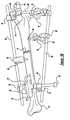
- FIGS. 1A and 1Billustrate a first exemplary construct of components of the external fixation system according to the teachings of the preferred embodiment of the present invention in operative association with a tibia.
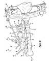
- FIG. 2illustrates a second exemplary construct of components of the external fixation system according to the teachings of the preferred embodiment of the present invention in operative association with a tibia, the second construct incorporating a compression/distraction arrangement.
- FIGS. 3A and 3Billustrate a third exemplary construct of components of the external fixation system according to the teachings of the preferred embodiment of the present invention in operative association with a tibia, the third construct incorporating a ring assembly.
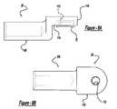
- FIGS. 4A and 4Bare views of a universal clamp assembly of the external fixation system according to the teachings of the preferred embodiment of the present invention.
- FIGS. 5A through 5Care views of a bar-to-bar clamp body of the external fixation system according to the teachings of the preferred embodiment of the present invention.
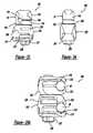
- FIGS. 6A and 6Bare views of a three pin clamp assembly of the external fixation system according to the teachings of the preferred embodiment of the present invention.
- FIGS. 7A and 7Bare views of a five pin clamp assembly of the external fixation system according to the teachings of the preferred embodiment of the present invention.
- FIGS. 8A and 8Bare views of a telescoping post of the external fixation system according to the teachings of the preferred embodiment of the present invention.
- FIGS. 9A and 9Bare views of a first ring connector assembly of the external fixation system according to the teachings of the preferred embodiment of the present invention.
- FIGS. 10A and 10Bare views of a second ring connector assembly of the external fixation system according to the teachings of the preferred embodiment of the present invention.
- FIGS. 11A through 11Dare views of a bone pin clamp body of the external fixation system according to the teachings of the preferred embodiment of the present invention.
- FIGS. 12A through 12Care views of a post assembly of the external fixation system according to the teachings of the preferred embodiment of the present invention.
- FIG. 13is a side elevational view a bar clamping unit of a compression/distraction arrangement of the external fixation system according to the teachings of the preferred embodiment of the present invention.
- FIGS. 14A through 14Care views of a variable connector body of the external fixation system according to the teachings of the preferred embodiment of the present invention.
- FIG. 15is a side elevational view of the bar clamping unit and threaded rod receiving unit the compression/distraction assembly of the external fixation system according to the teachings of the preferred embodiment of the present invention.
- FIG. 16is a perspective view of a clamp assembly according to the teachings of the preferred embodiment of the present invention, the clamp assembly adapted to receive first and second cylindrical rods.
- FIG. 17is another perspective view of the clamp assembly according to the teachings of the preferred embodiment of the present invention.
- FIG. 18is a rear view of the clamp assembly according to the teachings of the preferred embodiment of the present invention.
- FIG. 19is a side view of the clamp assembly according to the teachings of the preferred embodiment of the present invention.
- FIG. 20is a top view of the clamp assembly according to the teachings of the preferred embodiment of the present invention.
- FIG. 21is a bottom view of the clamp assembly according to the teachings of the preferred embodiment of the present invention.
- FIG. 22is a side view similar to FIG. 19 illustrating a cylindrical rod being introduced into an upper clamp member of the clamp assembly.
- FIG. 23is another view similar to FIG. 19 illustrating a cylindrical rod fully seated within the upper clamp member.
- FIG. 24is another side view similar to FIG. 19 illustrating a first cylindrical rod fully seated within the upper clamp member and a second cylindrical rod being introduced into a lower clamp member.
- FIG. 25is another side view similar to FIG. 19 illustrating the first and second cylindrical rods fully seated within the upper and lower clamp members, respectively, the upper and lower clamp members restrained from relative angular movement with respect to each other about an axis defined by a connecting fastener.
- FIG. 25Ais a side view similar to FIG. 25 illustrating locking of one of the cylindrical rods relative to the lower clamp member.
- FIG. 26is a side view similar to FIG. 25 illustrating the upper and lower clamp members separated from one another so as permit relative angular rotation about the axis defined by the connecting fastener.
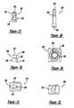
- FIG. 27is a side view of a fastener of the clamp assembly according to the teachings of the preferred embodiment of the present invention operative for engaging a locking plate and rigidly locking the cylindrical rod within the lower clamp member.
- FIG. 28is a side view of a fastener of the fastener connecting the upper and lower clamp members.
- FIG. 29is a side view of a nut for receiving the fastener connecting the upper and lower clamp members according to the teachings of the preferred embodiment of the present invention.
- FIG. 30is a top view of the lower clamp member.
- FIG. 31is a top view of a lower jaw member of the lower clamp member.
- FIG. 32is a bottom view of an upper jaw member of the lower clamp member.
- FIG. 33is a side view of a second clamp assembly constructed in accordance with the teachings of the preferred embodiment of the present invention, the second clamp assembly specifically adapted for connecting a cylindrical rod and a bone pin.
- FIG. 34is a rear view of the clamp assembly of FIG. 30 .
- FIGS. 1 through 3illustrated are three constructs of cooperating components of the system 10 for external fixation of bone according to the preferred embodiment of the present invention.
- a first construct of components of the system 10is shown securing a fracture 12 of a bone 14 .
- the system 10is illustrated as being used to secure a bone fracture 12 of a tibia 14 .
- the system 10is used to secure the bone portions 16 and 18 in a fixed relationship so as to permit the fractured portions to fuse properly.
- FIG. 2illustrates a second construct of the system 10 shown operatively attached to the tibia 14 .
- a third construct of the system 10is illustrated attached to the tibia 14 .
- FIGS. 1 through 3While the system 10 is shown throughout FIGS. 1 through 3 in conjunction with a tibia 14 , it will be appreciated that the system 10 may be used with other bones as well. It will also be appreciated that the three constructions illustrated in FIGS. 1 through 3 are merely exemplary applications.
- the components of the present inventionare illustrated to generally include a universal clamp assembly 20 , bar-to-bar clamp body 22 , a three pin clamp assembly 24 , a five pin clamp assembly 26 , a telescoping post 28 , a first ring connector assembly 30 , a second ring connector assembly 32 , a bone pin clamp body 34 , and a post assembly 36 .
- the componentsare illustrated to additionally include a compression/distraction arrangement 38 including a pair of clamping assemblies 40 and an externally threaded drive rod 42 .
- the componentsinclude a variable connector body 44 , a ring assembly 46 , and a plurality of cylindrical, smooth support rods 48 .
- the support rods 48include main support rods which are typically oriented to extend generally parallel to the axis of the bone 14 or at an acute angle relative to the bone 14 and supplemental support rods.
- the supplemental support rods 48 ′one of which is shown in FIG. 1B, may be provided in various lengths.
- the components of the system 10 of the present inventionmay be combined in an infinite number of combinations and orientations to secure and rigidly interconnect a plurality of bone screws or pins 50 which are engaged with the bone portions 16 and 18 .
- This flexibility of the system 10permits a surgeon to independently place a bone screw 50 at a limitless number of positions along the bone 14 or angular orientations with respect to the bone 14 .
- the universal clamp assembly 20 of the present inventionincludes a clamp portion 52 having first and second halves 54 and 56 which cooperate to define a bar receiving aperture 58 for receiving one of the support rods 48 , the telescoping post 28 or the post assembly 36 . It will be understood that in the exemplary embodiment the support rods 48 , telescoping post 28 and post assembly 36 each have a substantially identical diameter.
- the first and second halves 54 and 56include aligning apertures 60 and 62 , respectively, for receiving a locking bolt or fastener 64 .
- the aperture 62 of the second half 56includes a counterbored portion 66 for receiving a portion of a head 68 of the fastener 64 .
- An outer surface 70 of the first half 54is formed to include a serrated portion 72 having a plurality of serrations radially extending from the opening of the aperture 60 .
- the serrated portion 72is adapted to engage substantially identical serrated portions provided on cooperating components of the system 10 of the present invention as will be discussed below.
- An end 74 of the fastener 64 opposite the head 68is externally threaded.
- the fastener 64engages an internally threaded aperture of a cooperating component and is rotated to draw the cooperating component against the first half 56 , the first and second halves 56 of the clamp portion 52 are drawn together to thereby securely clamp one of the support rods 48 , for example, within the aperture 58 .
- the rod receiving aperture 58is sized to receive one of the support rods 48 , the telescoping post 28 or the post assembly 36 .
- the universal base clamp 20is the fundamental component of the system 10 of the present invention.
- the universal base clamp 20is designed to be easily placed anywhere along a support rod 48 , for example (even between two previously locked universal base clamps 20 ). This can be cone by sliding the first half 54 up the fastener 64 and then rotating the first half 54 ninety degrees. This feature allows a surgeon to add components during the application without the inconvenience of unlocking clamps 20 already in place.
- the bar-to-bar clamp body 22 of the present inventionis illustrated.
- the bar-to-bar clamp body 22is generally C-shaped to define a rod receiving aperture 80 and includes first and second ends 76 and 78 which are spaced apart by an opening 82 .
- the first and second ends 76 and 78include aligning apertures 84 and 86 , respectively, for receiving a fastener such as the fastener 64 described above with respect to the universal clamp assembly 20 .
- the aperture 86 of the second end 78is internally threaded.
- An outer surface 88 of the first end 76is formed to include a serrated portion 72 .
- the bar-to-bar clamp body 22is attached to a cooperating component of the system 10 of the present invention through engagement of the fastener 64 with the apertures 84 and 86 .
- the serrated portions 72 of the componentsare interlocked thereby preventing relative rotation. Tightening of the fastener 64 draws the ends 76 and 78 of the bar-to-bar clamp body 22 toward one another.
- a support rods 48 , telescoping post 28 or post assembly 36 positioned within the aperture 80is secured relative to the bar-to-bar clamp body 22 and in turn secured relative to the cooperating component.
- the pin clamp assembly 24 of the present inventionis illustrated.
- the pin clamp assembly 24is operative for receiving and securing up to three bone pins 50 engaged with the bone 14 .
- the bone pin clamp 28includes a main body member 90 and a cover member 92 .
- the main body member 90defines three bone pin rests 94 .
- the bone pin rests or grooves 94are substantially V-shaped and are operable to engage the sides of the bone pins 50 .
- the cover member 92 of the pin clamp assembly 24is able to be inserted over the bone pins 50 when the bone pins 50 are located in the grooves 94 .
- the cover member 92includes a pair of apertures 96 which each allow a threaded fastener 98 to pass through the cover member 32 and into a threaded aperture 100 of the main body member 90 . Tightening of the fasteners 98 rotationally and longitudinally secures the bone pins 50 relative to the pin clamp assembly 24 .
- the base member 90 and the cover member 92are both formed to integrally include cylindrical extensions 102 and 104 , respectfully.
- the ends of each of the cylindrical extensions 102 and 104are both formed to include a serrated portion 72 .
- Each of the cylindrical extensions 102 and 104includes an internally threaded aperture 106 sized to receive a fastener 64 .
- the five pin clamp assembly 26is shown particularly in FIGS. 7A and 7B.
- the construction of the five pin clamp assembly 26is identical to the construction of the three pin clamp assembly 26 , with the exception that the five pin clamp assembly 26 is formed to include two additional bone pin rests 94 .
- the five pin clamp assembly 26includes three bone pin rests 94 between the fasteners 98
- the three pin clamp assembly 24includes a single bone pin rest 94 between the fasteners. Due to the similarity between the two pin clamp assemblies 24 and 26 , like reference numbers are used in the drawings.
- the telescoping post 28includes a cylindrical post portion 108 and a mounting flange portion 110 .
- the cylindrical post portion 108has a diameter substantially equal to the diameter of the support rods 48 and thereby may be securely received within rod receiving apertures of cooperating components of the system 10 of the present invention.
- the mounting flange portion 110includes an aperture 112 for receiving a fastener 64 .
- a lower side 114 of the mounting flange portion 110includes a serrated portion 72 for cooperating with the serrated portions of cooperating components of the system 10 in a manner discussed above.
- the first ring connector assembly 30 of the present inventionis illustrated.
- the first ring connector assemblyincludes a main body 116 and a fastener 118 .
- An upper portion 120 of the main body 116defines a vertically extending aperture 122 which is internally threaded to receive the externally threaded fastener 118 .
- a lower portion 124 of the main body 116includes a pair of spaced apart sides 126 and 128 and an aperture 130 horizontally passing therethrough. Both of the sides 126 and 128 are formed to include a serrated portion 72 radially surrounding the aperture 130 which is adapted to interface with cooperating components of the system 10 including a serrated portion 72 in a manner discussed above.
- the fastener 118is adapted to pass through one of a plurality of apertures formed in a frame 132 of the ring assembly 46 for securing the first ring connector assembly 32 thereto.
- the second ring connector assembly 32 of the present inventionis illustrated. Rather than interfacing with cooperating components of the system 10 including a serrated portion 72 , the second ring connector assembly 32 is adapted to interface with cooperating components including a rod receiving aperture, such as the universal clamp assembly 20 and the bar-to-bar clamp body 22 .
- the second ring connector assembly 32includes a main body portion 132 and a cylindrical extension 134 . To facilitate clamping within one of the rod receiving apertures, the cylindrical extension 134 has a diameter substantially equal to the support rods 48 .
- the main body 132defines a pair of apertures 136 which are internally threaded for receiving a pair of threaded fasteners 118 identical to the fastener described with respect to the first ring connector assembly 30 .
- the fasteners 118are adapted to pass through a pair of the plurality of apertures formed in the frame 132 of the ring assembly 46 for securing the second ring connector assembly thereto.
- the bone pin clamp body 34 of the present inventiondefines an aperture 138 for receiving a bone pin 50 .
- the pin clamp body 34includes an upper flange portion 140 and a lower flange portion 142 which are separated by a gap 144 .
- the gap 144intersects the aperture 138 .
- the upper and lower flange portions 140 and 142are formed to include aligning apertures 146 and 148 for receiving a fastener 64 .
- the aperture 148 of the lower flange portion 142is internally threaded.
- An upper surface 150 of the upper flange portion 140includes a serrated portion 72 surrounding the aperture 146 .
- the serrated portion 72is adapted to interface with serrated portions of cooperating components of the system 10 of the present invention in a manner discussed above.
- a cooperating componentis secured to the bone pin clamp body 34 with a fastener 64
- tightening of the fastener 64causes the gap 144 between the upper and lower flange portions 140 and 142 to decrease and the aperture 138 to slightly constrict.
- a bone pin 50 disposed within the aperture 138is longitudinally and rotationally fixed with respect to the bone pin clamp body 34 .
- the post assembly 36generally includes a cylindrical sleeve 152 and a threaded fastener 154 .
- the cylindrical sleeve 152includes a central portion 156 and first and second enlarged ends 158 and 160 .
- the cylindrical sleeve 152has a diameter substantially equal to the diameter of the support rods 48 and can similarly interface with cooperating components including a rod receiving aperture, such as the universal clamp assembly 20 , in a manner discussed above.
- the cylindrical sleeve 152defines an elongated aperture 162 for receiving the fastener 154 .
- An outer end of the first enlarged end 158includes a serrated portion 72 surrounding the aperture 162 .
- the fastener 154extends beyond the serrated portion and is externally threaded.
- An opposite end of the fastener 154includes a recess 164 for receiving a tool (not shown) used to rotate the fastener 154 relative to the cylindrical sleeve 152 .
- the serrated portion 72is adapted to interface with serrated portions 72 of cooperating components of the system 10 of the present invention in a manner discussed above.
- the serrated portion 72is particularly intended to cooperate with the 3 pin and 5 pin clamp assemblies.
- the variable connector body 44 of the present inventiongenerally includes a main body 166 and a cylindrical portion 168 extending from the main body 166 .
- the main body 166includes a pair of spaced apart sides 170 and 172 and an internally threaded aperture 174 passing therethrough. Both of the sides 170 and 172 are formed to include a serrated portion 72 radially surrounding the aperture 174 which is adapted to interface with cooperating components of the system 10 including a serrated portion 72 in a manner discussed above.
- the cylindrical portion 168has a diameter substantially equal to the diameter of the support rods 48 and thereby may be securely received within rod receiving apertures of cooperating components of the system 10 of the present invention in a manner discussed above.
- the clamping assemblies 40 of the distraction arrangement 38each include a bar clamping unit 178 and a threaded rod receiving unit 180 .
- the bar clamping unit 178includes a lower portion 182 and a pair of substantially identical upper portions 184 .
- Each of the upper portions 184cooperates with the lower portion 182 to define an aperture 186 for receiving one of the support rods 48 .
- the upper portions 184each include an apertures 188 which each allow a threaded fastener 190 to pass therethrough and into an aligning threaded aperture 192 provided in the lower portion 182 . Tightening of the fasteners 190 secures the support rods 48 .
- a pair of the support rods 48are non-rotatably retained in a parallel and spaced apart relationship.
- the threaded rod receiving unit 180 of each of the clamping assemblies 40includes a first aperture (not specifically shown) which is internally threaded for receiving the drive rod 42 .
- the clamping assemblies 40additionally include a second aperture 194 oriented substantially perpendicular to the first aperture.
- the second aperture 194allows a threaded fastener 196 to pass therethrough and into an aligning internally threaded aperture 198 provided in the lower portion 182 of the bar clamping unit 178 for securing the bar clamping unit 178 to the threaded rod receiving unit 180 .
- the threads of the apertures receiving the drive rod 42progress in opposing directions.
- the fastener 190 of a first one of the bar clamping units 178 which is associated with one of the support rods 48must be loosened to permit the support rod 48 to slide within the aperture 186 .
- the fastener 190 of a second of the bar clamping units 178 which is associated with the other one of the support rods 48must be loosened to permit the support rod 48 to slide in its aperture 186 .
- one of the bar clamping units 178is permitted to translate with respect to one of the support rods 48 and the other of the clamping units 178 is permitted to translate relative to the other of the support rods 48 .
- rotation of the drive rod 42 in a first directioncauses relative movement between the clamping assemblies 40 such that they approach one another and the bone 14 is compressed.
- rotation of the drive rod 42 in a second directioncauses relative movement between the clamping assemblies 40 such that they diverge from one another and the bone 14 is distracted.
- the ring assembly 46 of the present inventionis shown in the exemplary construct of FIGS. 3A and 3B.
- a substantially identical ring assemblyis shown and described in commonly assigned U.S. Ser. No. 09/086,256, filed Jun. 28, 1998.
- U.S. Ser. No. 09/086,256is incorporated by reference as if fully set forth herein.
- the clamp assembly 200is operative for connecting first and second elongated members.
- the first and second elongated membersare cylindrical in shape and identical to the support rods 48 discussed above.
- the clamp assembly 200is illustrated to include a first or lower clamp member 202 and a second or upper clamp member 204 .
- Terms of orientationincluding but not limited to such as “upper” and “lower” will be used herein for purposes of referencing the drawings and are not to be considered limiting.
- the clamp assembly 200is equally operative in any particular orientation and is not limited to the orientation shown in the drawings.
- the first and second clamp members 202 and 204are connected by a fastener 206 in a manner to be further discussed below.
- the fastener 206is operative for locking the cylindrical rod 48 relative the second clamp member 204 .
- the fastener 206is further operative for arresting the relative angular orientations of the first and second clamp members 202 and 204 about an axis A (identified in FIG. 19) defined by the fastener 206 .
- a second fastener 207operates to lock a cylindrical rod 48 within the first clamp member 202 .
- the first clamp member 202includes an upper jaw portion 208 and a lower jaw portion 210 which cooperate to define an opening 212 for receiving the cylindrical rod 48 .
- the upper jaw portion 208 of the first clamp member 202is formed to include a pair of spaced apart and cantilevered lever arms 214 .
- the lever arms 214are adapted to be resiliently deflected upon introduction of the cylindrical rod 48 into the opening 212 . In this manner, the cylindrical rod 48 is temporarily held in place until the upper and lower jaw portions 208 and 210 are locked down.
- the lower jaw portion 210includes a reduced width portion 216 which is received between the cantilevered arms 214 . In this manner, relative rotation between the upper and lower jaw portions 208 and 210 is prevented.
- the fastener 207extends through an aperture 220 (FIG. 22) provided in the lower jaw portion 210 and threadably engages an internally threaded aperture 222 formed in a locking plate 224 of the upper jaw portion 208 .
- the upper jaw portion 208defines a laterally extending slot 226 in which the locking plate 224 is disposed.
- the fastener 207preferably includes a spherically shaped portion 228 which is matingly received within a spherically shaped counterbored portion of the aperture 220 .
- an upper side of the aperture 220includes a relieved portion 229 which accommodates pivoting of the lower jaw 210 on the fastener 207 as shown in FIG. 24, for example.
- An end portion of the fastener 207includes a hexagonally shaped surface 230 engageable by a conventional drive tool (such as a wrench or socket (not shown).
- a conventional drive toolsuch as a wrench or socket (not shown).
- the second clamp member 204similarly includes an upper jaw portion 232 and a lower jaw portion 234 .
- the upper jaw portion 232 of the second clamp member 204is similar in construction and operation to the lower jaw member 210 of the first clamp member 202 and the lower jaw member 234 of the second clamp member 204 is similar in construction and operation to the upper jaw member 208 of the first clamp member 202 .
- the lower jaw member 234 of the second coupling member 204includes a pair of spaced apart and cantilevered lever arms 236 .
- a cylindrical rod 48is temporarily held in place through a snap-fit with the pair of lever arms 236 .
- Aligning apertures 238 and 240are provided in the upper and lower jaw portions 232 and 234 and receive a nut member 242 (shown particularly in FIG. 29 ).
- the nut member 242has a generally rectangular end 244 with convexly curved opposing sides 246 and 248 connected by generally flat sides. The convexly curved opposing sides 246 and 248 are matingly received within the aperture 238 of the upper jaw portion 232 .
- the aperture 238includes a relieved portion which accommodates pivoting of the upper jaw portion 232 about the axis A (identified in FIG. 19) as shown in FIG. 22 .
- the rectangular shape of the aperture 238limits the pivoting movement of the upper jaw portion 232 to a single plane.
- a cylindrical portion 250 of the nut member 242is received within the cylindrical aperture 240 of the lower jaw portion 234 .
- the nut member 242defines an internally threaded aperture 252 for receiving an externally threaded end 254 of the fastener 206 .
- the fastener 207is hollow and defines a longitudinal channel 256 for receiving the fastener 206 in a co-axial arrangement.
- the fastener 206is formed to include a hexagonal shaped recess 258 at either end such that the fastener 206 can be rotated from either end with a conventional drive tool (not shown).
- a conventional drive toolnot shown.
- the first and second clamp members 202 and 204are formed to include cooperating serrations.
- an upper surface 260 of the first coupler 202includes a serrated portion 262 having a plurality of serrations radially extending from an aperture 264 .
- the serrated portion 262is adapted to engage a substantially identical serrated portion (not particularly shown) provided on an adjacent lower surface of the second clamp member 204 .
- FIG. 22shows a first cylindrical rod in a seated position within the second clamp member 204 . As illustrated, the lever arms 236 remain bent and maintain a force on the rod 48 to prevent it from falling out of the clamp assembly 200 .
- a second cylindrical rodis similarly inserted between the jaw portions 208 and 210 of the first clamp member 202 .
- the fastener 207has been tightened such that the locking plate 204 has been drawn downward to correspondingly cause the upper jaw member 208 to be drawn down against the lower jaw member 210 and lock the cylindrical rod 48 therebetween.
- the fastener 206has been initially tightened such that the first and second clamp members 202 and 204 are drawn together and the cooperating serrations 262 prevent relative rotation therebetween.
- the clamp assembly 200can be used for bone lengthening.
- the upper cylindrical rod 48can be moved relative to the lower cylindrical rod 48 without losing the position of the first clamp member 202 or the angle between the first and second clamp members 202 and 204 .
- the clamp assembly 200is illustrated in FIG. 26 with the fastener 206 fully loosen. In this position, a gap 266 exists between the first and second clamp members 202 and 204 and the corresponding plurality of serrations 262 are separated. As such, the first and second clamp members 202 and 204 can be rotated relative to one another about the axis A.
- FIGS. 33 and 34a variation of the clamp assembly 200 is illustrated. More particularly, a clamp assembly 300 is illustrated for connecting a bone screw or pin 50 and a cylindrical rod 48 .
- the clamp assembly 300is illustrated to include the bone pin clamp body 34 described above with particular reference to FIGS. 11A-11D and the first clamp member 202 of the clamp assembly 200 .
- the fasteners 206 and 207are employed in much the same manner discussed above with respect to the clamp assembly 200 . Briefly, the fastener 206 threadably engages the locking plate 204 such that tightening of the fastener 207 draws the locking plate downward and correspondingly draws the upper jaw portion 208 towards the lower jaw portion 210 to lockingly capture a cylindrical rod 48 therebetween.
- the lever arms 214 of the first clamp member 202operate in the manner discussed above to temporarily retain the cylindrical rod 48 .
- the fastener 206extends through the fastener 207 and threadably engages an internally threaded aperture 148 of the flange portion 142 of the pin clamp body 34 .
- Initial tightening of the fastener 206draws the pin clamp body 34 toward the first clamp member 202 such that adjacent serrations 262 of the components engage and prevent relative rotation. Further rotation of the fastener 206 causes the gap 144 between the flange portions 140 and 142 to decrease the aperture 138 to slightly constrict.
- the bone pin 50 disposed with the aperture 138is longitudinally and rotationally fixed with respect to the bone pin clamp body 34 .
Landscapes
- Health & Medical Sciences (AREA)
- Orthopedic Medicine & Surgery (AREA)
- Life Sciences & Earth Sciences (AREA)
- Surgery (AREA)
- Medical Informatics (AREA)
- Engineering & Computer Science (AREA)
- Biomedical Technology (AREA)
- Heart & Thoracic Surgery (AREA)
- Nuclear Medicine, Radiotherapy & Molecular Imaging (AREA)
- Molecular Biology (AREA)
- Animal Behavior & Ethology (AREA)
- General Health & Medical Sciences (AREA)
- Public Health (AREA)
- Veterinary Medicine (AREA)
- Surgical Instruments (AREA)
- Mutual Connection Of Rods And Tubes (AREA)
- Clamps And Clips (AREA)
Abstract
Description
Claims (29)
Priority Applications (4)
| Application Number | Priority Date | Filing Date | Title |
|---|---|---|---|
| US09/918,138US6616664B2 (en) | 1999-10-21 | 2001-07-30 | Clamp assembly for an external fixation system |
| US10/074,329US6702814B2 (en) | 1999-10-21 | 2002-02-12 | Clamp assembly for an external fixation system |
| PCT/US2002/023163WO2003011174A2 (en) | 2001-07-30 | 2002-07-19 | Clamp assembly for an external fixation system |
| AU2002319619AAU2002319619A1 (en) | 2001-07-30 | 2002-07-19 | Clamp assembly for an external fixation system |
Applications Claiming Priority (2)
| Application Number | Priority Date | Filing Date | Title |
|---|---|---|---|
| US09/422,377US6277119B1 (en) | 1999-10-21 | 1999-10-21 | External fixation system |
| US09/918,138US6616664B2 (en) | 1999-10-21 | 2001-07-30 | Clamp assembly for an external fixation system |
Related Parent Applications (1)
| Application Number | Title | Priority Date | Filing Date |
|---|---|---|---|
| US09/422,377Continuation-In-PartUS6277119B1 (en) | 1999-10-21 | 1999-10-21 | External fixation system |
Related Child Applications (1)
| Application Number | Title | Priority Date | Filing Date |
|---|---|---|---|
| US10/074,329Continuation-In-PartUS6702814B2 (en) | 1999-10-21 | 2002-02-12 | Clamp assembly for an external fixation system |
Publications (2)
| Publication Number | Publication Date |
|---|---|
| US20020026190A1 US20020026190A1 (en) | 2002-02-28 |
| US6616664B2true US6616664B2 (en) | 2003-09-09 |
Family
ID=41278255
Family Applications (1)
| Application Number | Title | Priority Date | Filing Date |
|---|---|---|---|
| US09/918,138Expired - LifetimeUS6616664B2 (en) | 1999-10-21 | 2001-07-30 | Clamp assembly for an external fixation system |
Country Status (3)
| Country | Link |
|---|---|
| US (1) | US6616664B2 (en) |
| AU (1) | AU2002319619A1 (en) |
| WO (1) | WO2003011174A2 (en) |
Cited By (69)
| Publication number | Priority date | Publication date | Assignee | Title |
|---|---|---|---|---|
| US20020177754A1 (en)* | 2001-05-23 | 2002-11-28 | Phillips Burns P. | Retractor clamp assembly |
| US20030149429A1 (en)* | 2002-02-04 | 2003-08-07 | Joseph Ferrante | External fixation system |
| US20030149430A1 (en)* | 2002-02-04 | 2003-08-07 | Joseph Ferrante | Devices, systems, and methods for placing and positioning fixation elements in external fixation systems |
| US20040044344A1 (en)* | 2000-02-02 | 2004-03-04 | Winquist Robert A. | Adjustable bone stabilizing frame system |
| US20040138659A1 (en)* | 2003-01-10 | 2004-07-15 | Ed Austin | External fixation apparatus and method |
| US20050080321A1 (en)* | 2003-10-08 | 2005-04-14 | Minnesota Scientific, Inc. | Surgical clamp |
| EP1627608A1 (en) | 2004-08-20 | 2006-02-22 | Stryker Trauma SA | Clamp element and joint element |
| EP1661523A1 (en) | 2004-11-30 | 2006-05-31 | Stryker Trauma SA | Insert for clamp element, clamp element with such insert and joint formed therewith |
| US20060167453A1 (en)* | 2000-12-14 | 2006-07-27 | Hoffmann-Clair Mindy L | Multipin clamp and rod attachment |
| US20060177263A1 (en)* | 2005-02-09 | 2006-08-10 | Stryker Trauma S.A. | External fixation clamp |
| US7125380B2 (en)* | 2000-08-08 | 2006-10-24 | Warsaw Orthopedic, Inc. | Clamping apparatus and methods |
| US20060241590A1 (en)* | 2005-04-25 | 2006-10-26 | Jean-Noel Bordeaux | Outrigger with locking mechanism |
| US20060255521A1 (en)* | 2003-06-26 | 2006-11-16 | Peter Brunner | Clamp for external fixation |
| US20070038217A1 (en)* | 2005-08-09 | 2007-02-15 | Brown Daniel G | Orthopaedic fixation clamp and method |
| EP1820461A1 (en) | 2006-02-21 | 2007-08-22 | Stryker Trauma SA | Clamping and articulation element |
| EP1862135A1 (en) | 2006-05-29 | 2007-12-05 | Stryker Trauma SA | Clamping element and insert therefor |
| US20080086134A1 (en)* | 2006-10-04 | 2008-04-10 | Butler Michael S | Multi-axial spinal cross-connectors |
| US20080214899A1 (en)* | 2003-04-02 | 2008-09-04 | Mulac Anthony J | Crank retractor handle |
| US20080247818A1 (en)* | 2004-03-10 | 2008-10-09 | Marc Oesch | Device For Mutual Positioning of Longitudinal Building Components |
| US7507248B2 (en) | 2001-04-06 | 2009-03-24 | Ldr Medical | Spinal osteosynthesis device and preparation method |
| US20090177234A1 (en)* | 2008-01-04 | 2009-07-09 | Butler Michael S | Spinal Cross-Connector With Spinal Extensor Muscle Curvature |
| US20090204156A1 (en)* | 2008-02-07 | 2009-08-13 | K2M, Inc. | Automatic lengthening bone fixation device |
| US20090254086A1 (en)* | 2005-10-11 | 2009-10-08 | Implantvet S.L. | Articulated Joint for Mutually Locking Rods and/or Pins in an External Fixation Device for Reducing Bone Fractures |
| US20090264710A1 (en)* | 2006-04-29 | 2009-10-22 | Comis Orthopaedics Limited | Surgical apparatus |
| US20090326532A1 (en)* | 2008-06-30 | 2009-12-31 | Depuy Products, Inc. | External fixator |
| US7758582B2 (en) | 2002-06-14 | 2010-07-20 | Smith & Nephew, Inc. | Device and methods for placing external fixation elements |
| USD633208S1 (en) | 2009-09-11 | 2011-02-22 | Stryker Trauma Ag | External fixation clamp |
| US20110087226A1 (en)* | 2009-09-11 | 2011-04-14 | Stryker Trauma Sa | Easy to clean clamping device |
| US8092542B2 (en) | 2000-08-08 | 2012-01-10 | Warsaw Orthopedic, Inc. | Implantable joint prosthesis |
| US8162988B2 (en) | 2001-10-18 | 2012-04-24 | Ldr Medical | Plate for osteosynthesis device and method of preassembling such device |
| US8162984B2 (en) | 2009-02-20 | 2012-04-24 | K2M, Inc. | Forced growth axial growing spine device |
| USD663030S1 (en) | 2011-06-14 | 2012-07-03 | Styker Trauma SA | Fixation clamp |
| US8221457B2 (en) | 2001-10-18 | 2012-07-17 | Ldr Medical | Progressive approach osteosynthesis device and preassembly method |
| US8241334B2 (en) | 2007-07-13 | 2012-08-14 | Life Spine, Inc. | Spinal cross-connector |
| US8343219B2 (en) | 2007-06-08 | 2013-01-01 | Ldr Medical | Intersomatic cage, intervertebral prosthesis, anchoring device and implantation instruments |
| USD682426S1 (en) | 2011-06-14 | 2013-05-14 | Stryker Trauma Sa | Fixation clamp |
| USD683461S1 (en) | 2010-12-14 | 2013-05-28 | Stryker Trauma Sa | Hinge coupling |
| US20130158551A1 (en)* | 2006-10-13 | 2013-06-20 | Stryker Trauma Sa | Prevention of re-use of a medical device |
| US8523858B2 (en) | 2005-06-21 | 2013-09-03 | DePuy Synthes Products, LLC | Adjustable fixation clamp and method |
| US8685023B2 (en) | 2010-12-14 | 2014-04-01 | Stryker Trauma Sa | Fixation clamp |
| USD704840S1 (en) | 2010-12-14 | 2014-05-13 | Stryker Trauma Sa | Hinge coupling |
| US8758343B2 (en) | 2005-04-27 | 2014-06-24 | DePuy Synthes Products, LLC | Bone fixation apparatus |
| US8827998B2 (en) | 2010-12-14 | 2014-09-09 | Stryker Trauma Sa | Fixation clamp |
| US8845691B2 (en) | 2003-09-01 | 2014-09-30 | Ldr Medical | Osseous anchoring implant with a polyaxial head and method for installing the implant |
| US20140324045A1 (en)* | 2009-05-15 | 2014-10-30 | Stryker Trauma Sa | Fixation clamp |
| USD720853S1 (en) | 2010-12-14 | 2015-01-06 | Stryker Trauma Sa | Fixation clamp |
| US8945129B2 (en) | 2010-12-14 | 2015-02-03 | Stryker Trauma Sa | Fixation clamp with thumbwheel |
| US9131963B2 (en) | 2011-03-08 | 2015-09-15 | Life Spine, Inc. | Posterior cross connector assembly |
| US20150272625A1 (en)* | 2007-09-27 | 2015-10-01 | Zimmer, Inc. | Method and clamping apparatus for external fixation and stabilization |
| US9326795B2 (en) | 2001-12-12 | 2016-05-03 | Ldr Medical | Implant for osseous anchoring with polyaxial head |
| US9393045B2 (en) | 2013-03-15 | 2016-07-19 | Biomet Manufacturing, Llc. | Clamping assembly for external fixation system |
| US20160235421A1 (en)* | 2015-02-18 | 2016-08-18 | Clemson University | Positioning Bracket for Multiple Bone Tunnel Drill Guides |
| US9539029B1 (en)* | 2015-12-03 | 2017-01-10 | Globus Medical, Inc. | External fixator assembly |
| US9675389B2 (en) | 2009-12-07 | 2017-06-13 | Samy Abdou | Devices and methods for minimally invasive spinal stabilization and instrumentation |
| US9707015B2 (en) | 2014-01-14 | 2017-07-18 | Life Spine, Inc. | Implant for immobilizing cervical vertebrae |
| US9770272B2 (en) | 2012-12-12 | 2017-09-26 | Wright Medical Technology, Inc. | Orthopedic compression/distraction device |
| US20180098791A1 (en)* | 2015-04-15 | 2018-04-12 | Umc Utrecht Holding B.V. | Coupling device for in an orthopaedic system |
| US9962188B2 (en) | 2013-10-29 | 2018-05-08 | Cardinal Health 247. Inc. | External fixation system and methods of use |
| US10010350B2 (en) | 2016-06-14 | 2018-07-03 | Stryker European Holdings I, Llc | Gear mechanisms for fixation frame struts |
| US10548740B1 (en) | 2016-10-25 | 2020-02-04 | Samy Abdou | Devices and methods for vertebral bone realignment |
| US10575961B1 (en) | 2011-09-23 | 2020-03-03 | Samy Abdou | Spinal fixation devices and methods of use |
| US10695105B2 (en) | 2012-08-28 | 2020-06-30 | Samy Abdou | Spinal fixation devices and methods of use |
| US10857003B1 (en) | 2015-10-14 | 2020-12-08 | Samy Abdou | Devices and methods for vertebral stabilization |
| US10874433B2 (en) | 2017-01-30 | 2020-12-29 | Stryker European Holdings I, Llc | Strut attachments for external fixation frame |
| US10918498B2 (en) | 2004-11-24 | 2021-02-16 | Samy Abdou | Devices and methods for inter-vertebral orthopedic device placement |
| US10973648B1 (en) | 2016-10-25 | 2021-04-13 | Samy Abdou | Devices and methods for vertebral bone realignment |
| US11006982B2 (en) | 2012-02-22 | 2021-05-18 | Samy Abdou | Spinous process fixation devices and methods of use |
| US11173040B2 (en) | 2012-10-22 | 2021-11-16 | Cogent Spine, LLC | Devices and methods for spinal stabilization and instrumentation |
| US11179248B2 (en) | 2018-10-02 | 2021-11-23 | Samy Abdou | Devices and methods for spinal implantation |
Families Citing this family (21)
| Publication number | Priority date | Publication date | Assignee | Title |
|---|---|---|---|---|
| DE502004010444D1 (en) | 2003-04-03 | 2010-01-14 | Medartis Ag | RECORDING FOR A BLOCKING ELEMENT AND BLOCKING ELEMENT |
| RU2265412C1 (en)* | 2004-03-25 | 2005-12-10 | Российский государственный медицинский университет | Device for osteosynthesis of supracondylar and transcondylar fractures of thighbone |
| RU2328242C2 (en)* | 2005-08-15 | 2008-07-10 | ГУ Научный Центр реконструктивной и восстановительной хирургии ВСНЦ СО РАМН (ГУ НЦ РВХ ВСНЦ СО РАМН) | Method of transosseous osteosynthesis of disphysial forearm damages and related device |
| RU2324448C2 (en)* | 2006-02-26 | 2008-05-20 | ГУ Научный Центр реконструктивной и восстановительной хирургии ВСНЦ СО РАМН (ГУ НЦ РВХ ВСНЦ СО РАМН) | Method of transosseous ostheosynthesis of monteggia fracture-disclocation of forearm bones and device |
| RU2314767C1 (en)* | 2006-04-03 | 2008-01-20 | Юрий Сергеевич Ильин | External fixation apparatus for intra-operational reposition and stabilization of position of post-traumatic bone fractures |
| RU2310413C1 (en)* | 2006-04-04 | 2007-11-20 | Олег Александрович Иньков | Method and device for combined ostheosynthesis |
| RU2321368C2 (en)* | 2006-04-13 | 2008-04-10 | Научно-исследовательский центр Татарстана "Восстановительная травматология и ортопедия" | Method for setting pelvic arc-type rest member of ilizarov apparatus when treating hip joint diseases |
| RU2353321C1 (en)* | 2007-10-25 | 2009-04-27 | Владимир Николаевич Ребров | Spoke bone fracture treatment apparatus |
| RU2352284C1 (en)* | 2007-10-25 | 2009-04-20 | Владимир Николаевич Ребров | Device for treatment of difficult fractures of radial bone |
| JP6106662B2 (en)* | 2011-05-17 | 2017-04-05 | ジンマー,インコーポレイティド | External fixed clamping system using a starting mechanism and stored spring energy |
| US9521965B2 (en)* | 2011-08-09 | 2016-12-20 | The Regents Of The University Of California | Mechanical pivot shift measurement to evaluate joints |
| CN102670289A (en)* | 2012-05-30 | 2012-09-19 | 上海市奉贤区中心医院 | Frame-type external fixator |
| DE102012112716A1 (en) | 2012-12-20 | 2014-06-26 | MAQUET GmbH | Medical support arm |
| DE102012112712A1 (en)* | 2012-12-20 | 2014-06-26 | MAQUET GmbH | instrument support |
| ITMI20130407A1 (en)* | 2013-03-18 | 2014-09-19 | Orthofix Srl | EXTERNAL FIXING DEVICE |
| US9381069B2 (en)* | 2014-02-20 | 2016-07-05 | Hiwin Technologies Corp. | Medical instrument holding apparatus |
| IT201700048427A1 (en)* | 2017-05-04 | 2018-11-04 | Orthofix Srl | Targeting system for guided insertion of a guide wire or bone screw |
| WO2022168057A1 (en)* | 2021-02-08 | 2022-08-11 | Nelson Saldanha Kiran Antony | System and devices for closed fracture reduction, deformity correction and fixation of bone |
| FI129484B (en)* | 2021-07-08 | 2022-03-15 | Hemitec Finland Oy | DEVICE INTENDED FOR WRAPPING MARBLE NAILS IN TRAILS |
| CN114732522B (en)* | 2022-03-14 | 2024-05-14 | 天津大学 | Flexible wire-driven fracture reduction surgical robot |
| US20250295433A1 (en)* | 2024-03-21 | 2025-09-25 | Orthopedic Designs North America, Inc. | Universal Fixator Clamp |
Citations (48)
| Publication number | Priority date | Publication date | Assignee | Title |
|---|---|---|---|---|
| US4488542A (en) | 1981-11-27 | 1984-12-18 | Per Helland | External setting and correction device for the treatment of bone fractures |
| US4553273A (en) | 1983-11-23 | 1985-11-19 | Henry Ford Hospital | Vertebral body prosthesis and spine stabilizing method |
| US4600000A (en) | 1982-09-16 | 1986-07-15 | Edwards Charles C | External fixation system |
| US4620533A (en) | 1985-09-16 | 1986-11-04 | Pfizer Hospital Products Group Inc. | External bone fixation apparatus |
| US4657550A (en) | 1984-12-21 | 1987-04-14 | Daher Youssef H | Buttressing device usable in a vertebral prosthesis |
| US4662365A (en) | 1982-12-03 | 1987-05-05 | Ortopedia Gmbh | Device for the external fixation of bone fragments |
| US4718151A (en)* | 1984-11-08 | 1988-01-12 | Minnesota Scientific, Inc. | Retractor apparatus |
| US4867404A (en)* | 1988-05-16 | 1989-09-19 | The United States Of America As Represented By The Department Of Health And Human Services | Flexible holder for a cystoscope or the like |
| US5020195A (en)* | 1989-01-27 | 1991-06-04 | Minnesota Scientific, Inc. | Clamping device for use on a retractor support |
| US5025780A (en)* | 1989-04-26 | 1991-06-25 | Farley Daniel K | Table mounted surgical retractor |
| US5211664A (en) | 1992-01-14 | 1993-05-18 | Forschungsinstitut, Davos Laboratorium Fur Experimentelle Chirugie | Shell structure for bone replacement |
| US5242240A (en)* | 1991-10-17 | 1993-09-07 | Minnesota Scientific, Inc. | Clamping device for a surgical retractor |
| US5261912A (en) | 1990-08-21 | 1993-11-16 | Synthes (U.S.A.) | Implant for an osteosynthesis device, in particular for spinal column correction |
| US5352224A (en) | 1990-11-29 | 1994-10-04 | Howmedica Gmbh | Correction implant for the human vertebral column |
| US5393161A (en) | 1990-12-10 | 1995-02-28 | Jaquet Orthopedie S.A. | External fixator |
| US5403315A (en) | 1992-04-29 | 1995-04-04 | Danek Medical, Inc. | Positionable spinal fixation device |
| US5451225A (en) | 1993-06-10 | 1995-09-19 | Texas Scottish Rite Hospital For Crippled Children | Fastener for external fixation device wires and pins |
| US5520689A (en) | 1992-06-04 | 1996-05-28 | Synthes (U.S.A.) | Osteosynthetic fastening device |
| US5527311A (en) | 1991-11-13 | 1996-06-18 | Howmedica Gmbh | Support for the human spine |
| US5534002A (en) | 1993-01-04 | 1996-07-09 | Danek Medical, Inc. | Spinal fixation system |
| US5542946A (en) | 1994-05-27 | 1996-08-06 | Sofamor S.N.C. | Hook for an occipito-cervical rod or plate of an occipito-cervical osteosynthesis instrumentation |
| US5601552A (en) | 1994-03-18 | 1997-02-11 | Sofamor, S.N.C. | Fixing device for a rigid transverse connection device between rods of a spinal osteosynthesis system |
| US5624440A (en) | 1996-01-11 | 1997-04-29 | Huebner; Randall J. | Compact small bone fixator |
| US5643258A (en) | 1994-08-10 | 1997-07-01 | Howmedica Gmbh | Device for stabilizing long bones |
| US5676666A (en) | 1994-08-23 | 1997-10-14 | Spinetech, Inc. | Cervical spine stabilization system |
| US5683389A (en) | 1994-12-05 | 1997-11-04 | Smith & Nephew, Inc. | External fixator for distal radius fractures |
| US5683390A (en) | 1994-02-22 | 1997-11-04 | Howmedica Gmbh | Correcting a spinal column |
| US5688274A (en) | 1995-10-23 | 1997-11-18 | Fastenetix Llc. | Spinal implant device having a single central rod and claw hooks |
| US5688272A (en) | 1995-03-30 | 1997-11-18 | Danek Medical, Inc. | Top-tightening transverse connector for a spinal fixation system |
| US5702393A (en) | 1995-12-07 | 1997-12-30 | Groupe Lepine | Assembly device for elongate components of osteosynthesis, especially spinal, equipment |
| US5709681A (en) | 1995-09-19 | 1998-01-20 | Pennig; Dietmar | Device for osteosynthesis |
| US5741252A (en) | 1996-03-25 | 1998-04-21 | Synthes U.S.A. | Adjustable clamp for bone fixation element |
| US5741254A (en) | 1993-04-19 | 1998-04-21 | Stryker Corporation | Implant for an ostheosynthesis device, in particular for the spine |
| US5746741A (en) | 1996-05-06 | 1998-05-05 | Tufts University | External fixator system |
| US5752954A (en) | 1994-09-06 | 1998-05-19 | Howmedica International | External fixation device |
| US5776134A (en)* | 1992-09-02 | 1998-07-07 | Advanced Spine Fixation Systems, Inc. | Low-profile spinal fixation system |
| US5782833A (en)* | 1996-12-20 | 1998-07-21 | Haider; Thomas T. | Pedicle screw system for osteosynthesis |
| WO1998032385A1 (en) | 1996-01-30 | 1998-07-30 | Implico B.V. | Means for anti-rotationally fixing two components together, particularly of an osteosynthetic fixator |
| US5863292A (en)* | 1996-09-26 | 1999-01-26 | Tosic; Aleksandar | Articulated external orthopedic fixation system and method of use |
| US5863293A (en) | 1996-10-18 | 1999-01-26 | Spinal Innovations | Spinal implant fixation assembly |
| US5888221A (en) | 1992-08-11 | 1999-03-30 | Gelbard; Steven D. | Spinal stabilization implant system |
| US5891144A (en) | 1996-05-10 | 1999-04-06 | Jaquet Orthopedie S.A. | External fixator |
| US5921985A (en) | 1998-02-10 | 1999-07-13 | Texas Scottish Rite Hospital | External fixation device and method |
| US5961515A (en) | 1995-03-01 | 1999-10-05 | Smith & Nephew, Inc. | External skeletal fixation system |
| US6017306A (en)* | 1997-05-30 | 2000-01-25 | Bristol-Myers Squibb Company | Clamp assembly for use with orthopaedic retractor frame assembly |
| US6077263A (en)* | 1997-08-13 | 2000-06-20 | Aesculap Ag & Co. Kg | Vertebral osteosynthetic system |
| US6083154A (en)* | 1997-10-23 | 2000-07-04 | Sofamor S.N.C. | Surgical instrumentation and method for retracting and shifting tissues |
| US6110173A (en)* | 1998-09-15 | 2000-08-29 | Advanced Spine Fixation Systems, Inc. | Transverse connector for spinal fixation systems |
Family Cites Families (2)
| Publication number | Priority date | Publication date | Assignee | Title |
|---|---|---|---|---|
| US6056748A (en)* | 1998-02-20 | 2000-05-02 | Weiner; Lon S. | Modular fixator assembly |
| US6162223A (en)* | 1999-04-09 | 2000-12-19 | Smith & Nephew, Inc. | Dynamic wrist fixation apparatus for early joint motion in distal radius fractures |
- 2001
- 2001-07-30USUS09/918,138patent/US6616664B2/ennot_activeExpired - Lifetime
- 2002
- 2002-07-19AUAU2002319619Apatent/AU2002319619A1/ennot_activeAbandoned
- 2002-07-19WOPCT/US2002/023163patent/WO2003011174A2/ennot_activeApplication Discontinuation
Patent Citations (51)
| Publication number | Priority date | Publication date | Assignee | Title |
|---|---|---|---|---|
| US4488542A (en) | 1981-11-27 | 1984-12-18 | Per Helland | External setting and correction device for the treatment of bone fractures |
| US4600000A (en) | 1982-09-16 | 1986-07-15 | Edwards Charles C | External fixation system |
| US4662365A (en) | 1982-12-03 | 1987-05-05 | Ortopedia Gmbh | Device for the external fixation of bone fragments |
| US4553273A (en) | 1983-11-23 | 1985-11-19 | Henry Ford Hospital | Vertebral body prosthesis and spine stabilizing method |
| US4718151A (en)* | 1984-11-08 | 1988-01-12 | Minnesota Scientific, Inc. | Retractor apparatus |
| US4657550A (en) | 1984-12-21 | 1987-04-14 | Daher Youssef H | Buttressing device usable in a vertebral prosthesis |
| US4620533A (en) | 1985-09-16 | 1986-11-04 | Pfizer Hospital Products Group Inc. | External bone fixation apparatus |
| US4867404A (en)* | 1988-05-16 | 1989-09-19 | The United States Of America As Represented By The Department Of Health And Human Services | Flexible holder for a cystoscope or the like |
| US5020195A (en)* | 1989-01-27 | 1991-06-04 | Minnesota Scientific, Inc. | Clamping device for use on a retractor support |
| US5025780A (en)* | 1989-04-26 | 1991-06-25 | Farley Daniel K | Table mounted surgical retractor |
| US5261912A (en) | 1990-08-21 | 1993-11-16 | Synthes (U.S.A.) | Implant for an osteosynthesis device, in particular for spinal column correction |
| US5352224A (en) | 1990-11-29 | 1994-10-04 | Howmedica Gmbh | Correction implant for the human vertebral column |
| US5393161A (en) | 1990-12-10 | 1995-02-28 | Jaquet Orthopedie S.A. | External fixator |
| US5242240A (en)* | 1991-10-17 | 1993-09-07 | Minnesota Scientific, Inc. | Clamping device for a surgical retractor |
| US5527311A (en) | 1991-11-13 | 1996-06-18 | Howmedica Gmbh | Support for the human spine |
| US5211664A (en) | 1992-01-14 | 1993-05-18 | Forschungsinstitut, Davos Laboratorium Fur Experimentelle Chirugie | Shell structure for bone replacement |
| US5403315A (en) | 1992-04-29 | 1995-04-04 | Danek Medical, Inc. | Positionable spinal fixation device |
| US5520689A (en) | 1992-06-04 | 1996-05-28 | Synthes (U.S.A.) | Osteosynthetic fastening device |
| US5888221A (en) | 1992-08-11 | 1999-03-30 | Gelbard; Steven D. | Spinal stabilization implant system |
| US5776134A (en)* | 1992-09-02 | 1998-07-07 | Advanced Spine Fixation Systems, Inc. | Low-profile spinal fixation system |
| US5534002A (en) | 1993-01-04 | 1996-07-09 | Danek Medical, Inc. | Spinal fixation system |
| US5562662A (en) | 1993-01-04 | 1996-10-08 | Danek Medical Inc. | Spinal fixation system and method |
| US5741254A (en) | 1993-04-19 | 1998-04-21 | Stryker Corporation | Implant for an ostheosynthesis device, in particular for the spine |
| US5451225A (en) | 1993-06-10 | 1995-09-19 | Texas Scottish Rite Hospital For Crippled Children | Fastener for external fixation device wires and pins |
| US5683390A (en) | 1994-02-22 | 1997-11-04 | Howmedica Gmbh | Correcting a spinal column |
| US5601552A (en) | 1994-03-18 | 1997-02-11 | Sofamor, S.N.C. | Fixing device for a rigid transverse connection device between rods of a spinal osteosynthesis system |
| US5743911A (en) | 1994-03-18 | 1998-04-28 | Sofamor S.N.C. | Fixing device for a rigid transverse connection device between rods of a spinal osteosynthesis system |
| US5542946A (en) | 1994-05-27 | 1996-08-06 | Sofamor S.N.C. | Hook for an occipito-cervical rod or plate of an occipito-cervical osteosynthesis instrumentation |
| US5643258A (en) | 1994-08-10 | 1997-07-01 | Howmedica Gmbh | Device for stabilizing long bones |
| US5676666A (en) | 1994-08-23 | 1997-10-14 | Spinetech, Inc. | Cervical spine stabilization system |
| US5752954A (en) | 1994-09-06 | 1998-05-19 | Howmedica International | External fixation device |
| US5683389A (en) | 1994-12-05 | 1997-11-04 | Smith & Nephew, Inc. | External fixator for distal radius fractures |
| US5961515A (en) | 1995-03-01 | 1999-10-05 | Smith & Nephew, Inc. | External skeletal fixation system |
| US5688272A (en) | 1995-03-30 | 1997-11-18 | Danek Medical, Inc. | Top-tightening transverse connector for a spinal fixation system |
| US5709681A (en) | 1995-09-19 | 1998-01-20 | Pennig; Dietmar | Device for osteosynthesis |
| US5688274A (en) | 1995-10-23 | 1997-11-18 | Fastenetix Llc. | Spinal implant device having a single central rod and claw hooks |
| US5702393A (en) | 1995-12-07 | 1997-12-30 | Groupe Lepine | Assembly device for elongate components of osteosynthesis, especially spinal, equipment |
| US5624440A (en) | 1996-01-11 | 1997-04-29 | Huebner; Randall J. | Compact small bone fixator |
| WO1998032385A1 (en) | 1996-01-30 | 1998-07-30 | Implico B.V. | Means for anti-rotationally fixing two components together, particularly of an osteosynthetic fixator |
| US5741252A (en) | 1996-03-25 | 1998-04-21 | Synthes U.S.A. | Adjustable clamp for bone fixation element |
| US5746741A (en) | 1996-05-06 | 1998-05-05 | Tufts University | External fixator system |
| US5891144A (en) | 1996-05-10 | 1999-04-06 | Jaquet Orthopedie S.A. | External fixator |
| US5863292A (en)* | 1996-09-26 | 1999-01-26 | Tosic; Aleksandar | Articulated external orthopedic fixation system and method of use |
| US5928230A (en) | 1996-09-26 | 1999-07-27 | Tosic; Aleksandar | Articulated external orthopedic fixation system and method of use |
| US5863293A (en) | 1996-10-18 | 1999-01-26 | Spinal Innovations | Spinal implant fixation assembly |
| US5782833A (en)* | 1996-12-20 | 1998-07-21 | Haider; Thomas T. | Pedicle screw system for osteosynthesis |
| US6017306A (en)* | 1997-05-30 | 2000-01-25 | Bristol-Myers Squibb Company | Clamp assembly for use with orthopaedic retractor frame assembly |
| US6077263A (en)* | 1997-08-13 | 2000-06-20 | Aesculap Ag & Co. Kg | Vertebral osteosynthetic system |
| US6083154A (en)* | 1997-10-23 | 2000-07-04 | Sofamor S.N.C. | Surgical instrumentation and method for retracting and shifting tissues |
| US5921985A (en) | 1998-02-10 | 1999-07-13 | Texas Scottish Rite Hospital | External fixation device and method |
| US6110173A (en)* | 1998-09-15 | 2000-08-29 | Advanced Spine Fixation Systems, Inc. | Transverse connector for spinal fixation systems |
Non-Patent Citations (3)
| Title |
|---|
| Howmedica brochure entitled "Howmedica Trauma Simple Solutions", copyright 1998, 26 pages. |
| Howmedica, Inc. manual entitled "External Fixation of a Complex Femoral Fracture, Frame Construction Manual", copyright 1981, 24 pages. |
| Synthes brochure entitled "The AO/ASIF Hybrid Fixator Technique Guide", copyright 1995, 25 pages. |
Cited By (152)
| Publication number | Priority date | Publication date | Assignee | Title |
|---|---|---|---|---|
| US7931650B2 (en) | 2000-02-02 | 2011-04-26 | Zimmer Technology, Inc. | Adjustable bone stabilizing frame system |
| US20040044344A1 (en)* | 2000-02-02 | 2004-03-04 | Winquist Robert A. | Adjustable bone stabilizing frame system |
| US8696668B2 (en) | 2000-02-02 | 2014-04-15 | Zimmer, Inc. | Adjustable bone stabilizing frame system |
| US20110172665A1 (en)* | 2000-02-02 | 2011-07-14 | Zimmer Technology, Inc. | Adjustable bone stabilizing frame system |
| US8092542B2 (en) | 2000-08-08 | 2012-01-10 | Warsaw Orthopedic, Inc. | Implantable joint prosthesis |
| US7125380B2 (en)* | 2000-08-08 | 2006-10-24 | Warsaw Orthopedic, Inc. | Clamping apparatus and methods |
| US7875030B2 (en)* | 2000-12-14 | 2011-01-25 | Synthes Usa, Llc | Multipin clamp and rod attachment |
| US20060167453A1 (en)* | 2000-12-14 | 2006-07-27 | Hoffmann-Clair Mindy L | Multipin clamp and rod attachment |
| US7507248B2 (en) | 2001-04-06 | 2009-03-24 | Ldr Medical | Spinal osteosynthesis device and preparation method |
| US20020177754A1 (en)* | 2001-05-23 | 2002-11-28 | Phillips Burns P. | Retractor clamp assembly |
| US6736775B2 (en)* | 2001-05-23 | 2004-05-18 | Boss Instruments Limited | Retractor clamp assembly |
| US8162988B2 (en) | 2001-10-18 | 2012-04-24 | Ldr Medical | Plate for osteosynthesis device and method of preassembling such device |
| US8221457B2 (en) | 2001-10-18 | 2012-07-17 | Ldr Medical | Progressive approach osteosynthesis device and preassembly method |
| US9326795B2 (en) | 2001-12-12 | 2016-05-03 | Ldr Medical | Implant for osseous anchoring with polyaxial head |
| US7887537B2 (en)* | 2002-02-04 | 2011-02-15 | Smith & Nephew, Inc. | External fixation system |
| US7004943B2 (en)* | 2002-02-04 | 2006-02-28 | Smith & Nephew, Inc. | Devices, systems, and methods for placing and positioning fixation elements in external fixation systems |
| US7048735B2 (en) | 2002-02-04 | 2006-05-23 | Smith & Nephew | External fixation system |
| US20050119656A1 (en)* | 2002-02-04 | 2005-06-02 | Joseph Ferrante | External fixation system |
| US20030149430A1 (en)* | 2002-02-04 | 2003-08-07 | Joseph Ferrante | Devices, systems, and methods for placing and positioning fixation elements in external fixation systems |
| US20030149429A1 (en)* | 2002-02-04 | 2003-08-07 | Joseph Ferrante | External fixation system |
| US7758582B2 (en) | 2002-06-14 | 2010-07-20 | Smith & Nephew, Inc. | Device and methods for placing external fixation elements |
| US20070255280A1 (en)* | 2003-01-10 | 2007-11-01 | Smith & Nephew, Inc. | External fixation apparatus and method |
| US8382755B2 (en) | 2003-01-10 | 2013-02-26 | Smith & Nephew, Inc. | External fixation apparatus and method |
| US7608074B2 (en) | 2003-01-10 | 2009-10-27 | Smith & Nephew, Inc. | External fixation apparatus and method |
| US20040138659A1 (en)* | 2003-01-10 | 2004-07-15 | Ed Austin | External fixation apparatus and method |
| US8696562B2 (en)* | 2003-04-02 | 2014-04-15 | Thompson Surgical Instruments, Inc. | Crank retractor handle |
| US20080214899A1 (en)* | 2003-04-02 | 2008-09-04 | Mulac Anthony J | Crank retractor handle |
| US20060255521A1 (en)* | 2003-06-26 | 2006-11-16 | Peter Brunner | Clamp for external fixation |
| US9492198B2 (en)* | 2003-06-26 | 2016-11-15 | DePuy Synthes Products, Inc. | Clamp for external fixation |
| US8845691B2 (en) | 2003-09-01 | 2014-09-30 | Ldr Medical | Osseous anchoring implant with a polyaxial head and method for installing the implant |
| US20060264711A1 (en)* | 2003-10-08 | 2006-11-23 | Minnesota Scientific, Inc. | Surgical clamp |
| US7097616B2 (en) | 2003-10-08 | 2006-08-29 | Minnesota Scientific, Inc. | Surgical clamp |
| WO2005034739A1 (en)* | 2003-10-08 | 2005-04-21 | Minnesota Scientific, Inc. | Surgical clamp |
| US20050080321A1 (en)* | 2003-10-08 | 2005-04-14 | Minnesota Scientific, Inc. | Surgical clamp |
| US20080247818A1 (en)* | 2004-03-10 | 2008-10-09 | Marc Oesch | Device For Mutual Positioning of Longitudinal Building Components |
| US10746214B2 (en) | 2004-03-10 | 2020-08-18 | DePuy Synthes Products, Inc. | Device for mutual positioning of longitudinal building components |
| US9089368B2 (en)* | 2004-03-10 | 2015-07-28 | DePuy Synthes Products, Inc. | Device for mutual positioning of longitudinal building components |
| US7241074B2 (en) | 2004-08-20 | 2007-07-10 | Stryker Trauma S.A. | Clamping and articulation element |
| US20060039750A1 (en)* | 2004-08-20 | 2006-02-23 | Stryker Trauma S.A. | Clamping and articulation element |
| EP1627608A1 (en) | 2004-08-20 | 2006-02-22 | Stryker Trauma SA | Clamp element and joint element |
| US11992423B2 (en) | 2004-11-24 | 2024-05-28 | Samy Abdou | Devices and methods for inter-vertebral orthopedic device placement |
| US10918498B2 (en) | 2004-11-24 | 2021-02-16 | Samy Abdou | Devices and methods for inter-vertebral orthopedic device placement |
| US11096799B2 (en) | 2004-11-24 | 2021-08-24 | Samy Abdou | Devices and methods for inter-vertebral orthopedic device placement |
| US8206388B2 (en) | 2004-11-30 | 2012-06-26 | Stryker Trauma S.A. | Insert for a clamping element, clamping element comprising said insert and universal joint produced therefrom |
| EP1661523A1 (en) | 2004-11-30 | 2006-05-31 | Stryker Trauma SA | Insert for clamp element, clamp element with such insert and joint formed therewith |
| US20080065068A1 (en)* | 2004-11-30 | 2008-03-13 | Roland Thomke | Insert for a Clamping Element, Clamping Element Comprising Said Insert and Universal Joint Produced Therefrom |
| US7491008B2 (en) | 2005-02-09 | 2009-02-17 | Stryker Trauma S.A. | External fixation clamp |
| US20060177263A1 (en)* | 2005-02-09 | 2006-08-10 | Stryker Trauma S.A. | External fixation clamp |
| US20090148232A1 (en)* | 2005-02-09 | 2009-06-11 | Stryker Trauma Sa | External fixation clamp |
| US7806623B2 (en) | 2005-02-09 | 2010-10-05 | Stryker Trauma S.A. | External fixation clamp |
| US20060241590A1 (en)* | 2005-04-25 | 2006-10-26 | Jean-Noel Bordeaux | Outrigger with locking mechanism |
| US9273715B2 (en) | 2005-04-25 | 2016-03-01 | DePuy Synthes Products, Inc. | Outrigger with locking mechanism |
| US7722609B2 (en) | 2005-04-25 | 2010-05-25 | Synthes Usa, Llc | Outrigger with locking mechanism |
| US8758343B2 (en) | 2005-04-27 | 2014-06-24 | DePuy Synthes Products, LLC | Bone fixation apparatus |
| US9545266B2 (en) | 2005-06-21 | 2017-01-17 | DePuy Synthes Products, Inc. | Adjustable fixation clamp and method |
| US8523858B2 (en) | 2005-06-21 | 2013-09-03 | DePuy Synthes Products, LLC | Adjustable fixation clamp and method |
| US20070038217A1 (en)* | 2005-08-09 | 2007-02-15 | Brown Daniel G | Orthopaedic fixation clamp and method |
| US20090036891A1 (en)* | 2005-08-09 | 2009-02-05 | Zimmer Technology, Inc. | Orthopaedic fixation clamp and method |
| US20090254086A1 (en)* | 2005-10-11 | 2009-10-08 | Implantvet S.L. | Articulated Joint for Mutually Locking Rods and/or Pins in an External Fixation Device for Reducing Bone Fractures |
| EP1820461A1 (en) | 2006-02-21 | 2007-08-22 | Stryker Trauma SA | Clamping and articulation element |
| US8840653B2 (en) | 2006-02-21 | 2014-09-23 | Stryker Trauma Sa | Clamping and articulation element |
| US8523923B2 (en) | 2006-02-21 | 2013-09-03 | Stryker Trauma Sa | Clamping and articulation element |
| US20090264710A1 (en)* | 2006-04-29 | 2009-10-22 | Comis Orthopaedics Limited | Surgical apparatus |
| WO2007137443A1 (en) | 2006-05-29 | 2007-12-06 | Stryker Trauma Sa | Clamping element and insert therefor |
| US8444643B2 (en) | 2006-05-29 | 2013-05-21 | Stryker Trauma Sa | Clamping element and insert therefor |
| EP1862135A1 (en) | 2006-05-29 | 2007-12-05 | Stryker Trauma SA | Clamping element and insert therefor |
| US20090306661A1 (en)* | 2006-05-29 | 2009-12-10 | Stryker Trauma Sa | Clamping Element and Insert Therefor |
| US20080086134A1 (en)* | 2006-10-04 | 2008-04-10 | Butler Michael S | Multi-axial spinal cross-connectors |
| US8721689B2 (en)* | 2006-10-04 | 2014-05-13 | Life Spine, Inc. | Multi-axial spinal cross-connectors |
| US9549762B2 (en)* | 2006-10-13 | 2017-01-24 | Stryker European Holdings I, Llc | Prevention of re-use of a medical device |
| US20130158551A1 (en)* | 2006-10-13 | 2013-06-20 | Stryker Trauma Sa | Prevention of re-use of a medical device |
| US8343219B2 (en) | 2007-06-08 | 2013-01-01 | Ldr Medical | Intersomatic cage, intervertebral prosthesis, anchoring device and implantation instruments |
| US10751187B2 (en) | 2007-06-08 | 2020-08-25 | Ldr Medical | Intersomatic cage, intervertebral prosthesis, anchoring device and implantation instruments |
| US8241334B2 (en) | 2007-07-13 | 2012-08-14 | Life Spine, Inc. | Spinal cross-connector |
| US9750535B2 (en)* | 2007-09-27 | 2017-09-05 | Zimmer, Inc. | Method and clamping apparatus for external fixation and stabilization |
| US20150272625A1 (en)* | 2007-09-27 | 2015-10-01 | Zimmer, Inc. | Method and clamping apparatus for external fixation and stabilization |
| US8080037B2 (en) | 2008-01-04 | 2011-12-20 | Life Spine, Inc. | Spinal cross-connector with spinal extensor muscle curvature |
| US20090177234A1 (en)* | 2008-01-04 | 2009-07-09 | Butler Michael S | Spinal Cross-Connector With Spinal Extensor Muscle Curvature |
| US8777995B2 (en) | 2008-02-07 | 2014-07-15 | K2M, Inc. | Automatic lengthening bone fixation device |
| US9339307B2 (en) | 2008-02-07 | 2016-05-17 | K2M, Inc. | Automatic lengthening bone fixation device |
| US20090204156A1 (en)* | 2008-02-07 | 2009-08-13 | K2M, Inc. | Automatic lengthening bone fixation device |
| US20090326532A1 (en)* | 2008-06-30 | 2009-12-31 | Depuy Products, Inc. | External fixator |
| US8187274B2 (en)* | 2008-06-30 | 2012-05-29 | Depuy Products, Inc. | External fixator |
| US8162984B2 (en) | 2009-02-20 | 2012-04-24 | K2M, Inc. | Forced growth axial growing spine device |
| US20140324045A1 (en)* | 2009-05-15 | 2014-10-30 | Stryker Trauma Sa | Fixation clamp |
| US10117677B2 (en) | 2009-05-15 | 2018-11-06 | Stryker European Holdings I, Llc | Fixation clamp |
| US9517086B2 (en) | 2009-05-15 | 2016-12-13 | Stryker European Holdings I, Llc | Fixation clamp |
| US9155562B2 (en)* | 2009-05-15 | 2015-10-13 | Stryker Trauma Sa | Fixation clamp |
| US10932821B2 (en) | 2009-05-15 | 2021-03-02 | Stryker European Operations Holdings Llc | Fixation clamp |
| US12161365B2 (en) | 2009-05-15 | 2024-12-10 | Stryker European Operations Holdings Llc | Fixation clamp |
| US8657819B2 (en) | 2009-09-11 | 2014-02-25 | Stryker Trauma Sa | Easy to clean clamping device |
| USD633208S1 (en) | 2009-09-11 | 2011-02-22 | Stryker Trauma Ag | External fixation clamp |
| US20110087226A1 (en)* | 2009-09-11 | 2011-04-14 | Stryker Trauma Sa | Easy to clean clamping device |
| US9675389B2 (en) | 2009-12-07 | 2017-06-13 | Samy Abdou | Devices and methods for minimally invasive spinal stabilization and instrumentation |
| US10543107B2 (en) | 2009-12-07 | 2020-01-28 | Samy Abdou | Devices and methods for minimally invasive spinal stabilization and instrumentation |
| US11918486B2 (en) | 2009-12-07 | 2024-03-05 | Samy Abdou | Devices and methods for minimally invasive spinal stabilization and instrumentation |
| US10857004B2 (en) | 2009-12-07 | 2020-12-08 | Samy Abdou | Devices and methods for minimally invasive spinal stabilization and instrumentation |
| US10610380B2 (en) | 2009-12-07 | 2020-04-07 | Samy Abdou | Devices and methods for minimally invasive spinal stabilization and instrumentation |
| US10945861B2 (en) | 2009-12-07 | 2021-03-16 | Samy Abdou | Devices and methods for minimally invasive spinal stabilization and instrumentation |
| US9259242B2 (en) | 2010-12-14 | 2016-02-16 | Stryker Trauma Sa | Fixation clamp |
| USD683461S1 (en) | 2010-12-14 | 2013-05-28 | Stryker Trauma Sa | Hinge coupling |
| US9402651B2 (en) | 2010-12-14 | 2016-08-02 | Stryker European Holdings I, Llc | Fixation clamp |
| US8685023B2 (en) | 2010-12-14 | 2014-04-01 | Stryker Trauma Sa | Fixation clamp |
| USD704840S1 (en) | 2010-12-14 | 2014-05-13 | Stryker Trauma Sa | Hinge coupling |
| US8827998B2 (en) | 2010-12-14 | 2014-09-09 | Stryker Trauma Sa | Fixation clamp |
| US9050135B2 (en) | 2010-12-14 | 2015-06-09 | Stryker Trauma Sa | Fixation clamp with thumbwheel |
| US8945129B2 (en) | 2010-12-14 | 2015-02-03 | Stryker Trauma Sa | Fixation clamp with thumbwheel |
| USD720853S1 (en) | 2010-12-14 | 2015-01-06 | Stryker Trauma Sa | Fixation clamp |
| US9131963B2 (en) | 2011-03-08 | 2015-09-15 | Life Spine, Inc. | Posterior cross connector assembly |
| USD663030S1 (en) | 2011-06-14 | 2012-07-03 | Styker Trauma SA | Fixation clamp |
| USD682426S1 (en) | 2011-06-14 | 2013-05-14 | Stryker Trauma Sa | Fixation clamp |
| US10575961B1 (en) | 2011-09-23 | 2020-03-03 | Samy Abdou | Spinal fixation devices and methods of use |
| US12167973B2 (en) | 2011-09-23 | 2024-12-17 | Samy Abdou | Spinal fixation devices and methods of use |
| US11324608B2 (en) | 2011-09-23 | 2022-05-10 | Samy Abdou | Spinal fixation devices and methods of use |
| US11517449B2 (en) | 2011-09-23 | 2022-12-06 | Samy Abdou | Spinal fixation devices and methods of use |
| US11839413B2 (en) | 2012-02-22 | 2023-12-12 | Samy Abdou | Spinous process fixation devices and methods of use |
| US11006982B2 (en) | 2012-02-22 | 2021-05-18 | Samy Abdou | Spinous process fixation devices and methods of use |
| US10695105B2 (en) | 2012-08-28 | 2020-06-30 | Samy Abdou | Spinal fixation devices and methods of use |
| US11559336B2 (en) | 2012-08-28 | 2023-01-24 | Samy Abdou | Spinal fixation devices and methods of use |
| US11918483B2 (en) | 2012-10-22 | 2024-03-05 | Cogent Spine Llc | Devices and methods for spinal stabilization and instrumentation |
| US11173040B2 (en) | 2012-10-22 | 2021-11-16 | Cogent Spine, LLC | Devices and methods for spinal stabilization and instrumentation |
| US10631900B2 (en) | 2012-12-12 | 2020-04-28 | Wright Medical Technology, Inc. | Orthopedic compression/distraction device |
| US9770272B2 (en) | 2012-12-12 | 2017-09-26 | Wright Medical Technology, Inc. | Orthopedic compression/distraction device |
| US9463045B2 (en) | 2013-03-15 | 2016-10-11 | Biomet Manufacturing, Llc | Polyaxial pivot housing for external fixation system |
| US9827011B2 (en) | 2013-03-15 | 2017-11-28 | Biomet Manufacturing, Llc | Polyaxial pivot housing for external fixation system |
| US9393045B2 (en) | 2013-03-15 | 2016-07-19 | Biomet Manufacturing, Llc. | Clamping assembly for external fixation system |
| US10299830B2 (en) | 2013-03-15 | 2019-05-28 | Biomet Manufacturing, Llc | Clamping assembly for external fixation system |
| US9962188B2 (en) | 2013-10-29 | 2018-05-08 | Cardinal Health 247. Inc. | External fixation system and methods of use |
| US9707015B2 (en) | 2014-01-14 | 2017-07-18 | Life Spine, Inc. | Implant for immobilizing cervical vertebrae |
| US10166046B2 (en) | 2014-01-14 | 2019-01-01 | Life Spine, Inc. | Implant for immobilizing cervical vertebrae |
| US10512488B2 (en) | 2014-01-14 | 2019-12-24 | Life Spine, Inc. | Implant for immobilizing cervical vertebrae |
| US10869680B2 (en)* | 2015-02-18 | 2020-12-22 | Clemson University | Positioning bracket for multiple bone tunnel drill guides |
| US20160235421A1 (en)* | 2015-02-18 | 2016-08-18 | Clemson University | Positioning Bracket for Multiple Bone Tunnel Drill Guides |
| US11141198B2 (en)* | 2015-04-15 | 2021-10-12 | Umc Utrecht Holding B.V. | Coupling device for in an orthopaedic system |
| US20180098791A1 (en)* | 2015-04-15 | 2018-04-12 | Umc Utrecht Holding B.V. | Coupling device for in an orthopaedic system |
| US11246718B2 (en) | 2015-10-14 | 2022-02-15 | Samy Abdou | Devices and methods for vertebral stabilization |
| US10857003B1 (en) | 2015-10-14 | 2020-12-08 | Samy Abdou | Devices and methods for vertebral stabilization |
| US9539029B1 (en)* | 2015-12-03 | 2017-01-10 | Globus Medical, Inc. | External fixator assembly |
| US11974781B2 (en) | 2016-06-14 | 2024-05-07 | Stryker European Operations Holdings Llc | Gear mechanisms for fixation frame struts |
| US11504160B2 (en) | 2016-06-14 | 2022-11-22 | Stryker European Operations Holdings Llc | Gear mechanisms for fixation frame struts |
| US12201325B2 (en) | 2016-06-14 | 2025-01-21 | Stryker European Operations Holdings Llc | Gear mechanisms for fixation frame struts |
| US10010350B2 (en) | 2016-06-14 | 2018-07-03 | Stryker European Holdings I, Llc | Gear mechanisms for fixation frame struts |
| US11259935B1 (en) | 2016-10-25 | 2022-03-01 | Samy Abdou | Devices and methods for vertebral bone realignment |
| US11752008B1 (en) | 2016-10-25 | 2023-09-12 | Samy Abdou | Devices and methods for vertebral bone realignment |
| US11058548B1 (en) | 2016-10-25 | 2021-07-13 | Samy Abdou | Devices and methods for vertebral bone realignment |
| US10744000B1 (en) | 2016-10-25 | 2020-08-18 | Samy Abdou | Devices and methods for vertebral bone realignment |
| US10548740B1 (en) | 2016-10-25 | 2020-02-04 | Samy Abdou | Devices and methods for vertebral bone realignment |
| US10973648B1 (en) | 2016-10-25 | 2021-04-13 | Samy Abdou | Devices and methods for vertebral bone realignment |
| US10874433B2 (en) | 2017-01-30 | 2020-12-29 | Stryker European Holdings I, Llc | Strut attachments for external fixation frame |
| US11723690B2 (en) | 2017-01-30 | 2023-08-15 | Stryker European Operations Holdings Llc | Strut attachments for external fixation frame |
| US12369948B2 (en) | 2017-01-30 | 2025-07-29 | Stryker European Operations Holdings Llc | Strut attachments for external fixation frame |
| US11179248B2 (en) | 2018-10-02 | 2021-11-23 | Samy Abdou | Devices and methods for spinal implantation |
Also Published As
| Publication number | Publication date |
|---|---|
| WO2003011174A2 (en) | 2003-02-13 |
| US20020026190A1 (en) | 2002-02-28 |
| AU2002319619A1 (en) | 2003-02-17 |
| WO2003011174A3 (en) | 2003-06-26 |
Similar Documents
| Publication | Publication Date | Title |
|---|---|---|
| US6616664B2 (en) | Clamp assembly for an external fixation system | |
| US6702814B2 (en) | Clamp assembly for an external fixation system | |
| CA1306914C (en) | Clamp and system for internal fixation | |
| US5976136A (en) | Method and apparatus for external bone fixator | |
| US8372073B2 (en) | Multi-pin clamp and rod attachment | |
| US5891144A (en) | External fixator | |
| US7449023B2 (en) | Method and apparatus for the external fixation and correction of bone | |
| US6409729B1 (en) | Clamp assembly for an external fixation system | |
| US6482206B2 (en) | Method and apparatus for external fixation of bones | |
| US6730086B2 (en) | Repositioning instrument to fixate bone-fractures | |
| US5766173A (en) | Distractor mechanism for external fixation device | |
| US5304177A (en) | Auxiliary device for osteosynthesis | |
| EP1093761B1 (en) | Spinal cross connector | |
| US5624440A (en) | Compact small bone fixator | |
| KR0128893B1 (en) | Variable Angle Bone Screw System | |
| US6520961B1 (en) | Method and apparatus for external fixation of a hinged joint | |
| US8382757B1 (en) | Adjustable fixator | |
| US6428540B1 (en) | Device for repositioning fractured bone fragments | |
| US5997537A (en) | Ring system for external fixation of bone and related method | |
| US5676664A (en) | Orthopaedic distractor and/or fixator | |
| JPH10509627A (en) | External fixation for distal radius fracture | |
| EP1482845B1 (en) | Clamp assembly for an external fixation system | |
| CN115568921A (en) | A spinal distraction device |
Legal Events
| Date | Code | Title | Description |
|---|---|---|---|
| AS | Assignment | Owner name:EBI, L.P., NEW JERSEY Free format text:ASSIGNMENT OF ASSIGNORS INTEREST;ASSIGNORS:WALULIK, STEPHEN B.;BAILEY, KIRK J.;REEL/FRAME:012032/0768 Effective date:20010710 | |
| STCF | Information on status: patent grant | Free format text:PATENTED CASE | |
| CC | Certificate of correction | ||
| FPAY | Fee payment | Year of fee payment:4 | |
| AS | Assignment | Owner name:BANK OF AMERICA, N.A., AS ADMINISTRATIVE AGENT FOR Free format text:SECURITY AGREEMENT;ASSIGNORS:LVB ACQUISITION, INC.;BIOMET, INC.;REEL/FRAME:020362/0001 Effective date:20070925 | |
| AS | Assignment | Owner name:EBI, LLC, NEW JERSEY Free format text:CHANGE OF NAME;ASSIGNOR:EBI, INC.;REEL/FRAME:021387/0450 Effective date:20080227 Owner name:EBI, LLC,NEW JERSEY Free format text:CHANGE OF NAME;ASSIGNOR:EBI, INC.;REEL/FRAME:021387/0450 Effective date:20080227 | |
| AS | Assignment | Owner name:EBI, LLC, NEW JERSEY Free format text:CORRECTIVE ASSIGNMENT TO CORRECT THE ASSIGNOR INCORRECTLY IDENTIFIED AS EBI, INC. ON ORIGINAL RECORDATION COVERSHEET SHOULD HAVE BEEN IDENTIFIED AS EBI, L.P. PREVIOUSLY RECORDED ON REEL 021387 FRAME 0450;ASSIGNOR:EBI, L.P.;REEL/FRAME:022727/0859 Effective date:20080227 Owner name:EBI, LLC,NEW JERSEY Free format text:CORRECTIVE ASSIGNMENT TO CORRECT THE ASSIGNOR INCORRECTLY IDENTIFIED AS EBI, INC. ON ORIGINAL RECORDATION COVERSHEET SHOULD HAVE BEEN IDENTIFIED AS EBI, L.P. PREVIOUSLY RECORDED ON REEL 021387 FRAME 0450. ASSIGNOR(S) HEREBY CONFIRMS THE ORIGINAL CONVEYANCE TEXT APPEARING IN NAME CHANGE DOCUMENTATION REFLECTS EBI, L.P. IS NOW KNOWN AS EBI, LLC.;ASSIGNOR:EBI, L.P.;REEL/FRAME:022727/0859 Effective date:20080227 Owner name:EBI, LLC, NEW JERSEY Free format text:CORRECTIVE ASSIGNMENT TO CORRECT THE ASSIGNOR INCORRECTLY IDENTIFIED AS EBI, INC. ON ORIGINAL RECORDATION COVERSHEET SHOULD HAVE BEEN IDENTIFIED AS EBI, L.P. PREVIOUSLY RECORDED ON REEL 021387 FRAME 0450. ASSIGNOR(S) HEREBY CONFIRMS THE ORIGINAL CONVEYANCE TEXT APPEARING IN NAME CHANGE DOCUMENTATION REFLECTS EBI, L.P. IS NOW KNOWN AS EBI, LLC.;ASSIGNOR:EBI, L.P.;REEL/FRAME:022727/0859 Effective date:20080227 | |
| FPAY | Fee payment | Year of fee payment:8 | |
| AS | Assignment | Owner name:BIOMET MANUFACTURING, LLC, INDIANA Free format text:ASSIGNMENT OF ASSIGNORS INTEREST;ASSIGNOR:EBI, LLC;REEL/FRAME:031307/0797 Effective date:20130925 | |
| FPAY | Fee payment | Year of fee payment:12 | |
| AS | Assignment | Owner name:LVB ACQUISITION, INC., INDIANA Free format text:RELEASE OF SECURITY INTEREST IN PATENTS RECORDED AT REEL 020362/ FRAME 0001;ASSIGNOR:BANK OF AMERICA, N.A., AS ADMINISTRATIVE AGENT;REEL/FRAME:037155/0133 Effective date:20150624 Owner name:BIOMET, INC., INDIANA Free format text:RELEASE OF SECURITY INTEREST IN PATENTS RECORDED AT REEL 020362/ FRAME 0001;ASSIGNOR:BANK OF AMERICA, N.A., AS ADMINISTRATIVE AGENT;REEL/FRAME:037155/0133 Effective date:20150624 |