US6616632B2 - Cannula for use with a medical syringe - Google Patents
Cannula for use with a medical syringeDownload PDFInfo
- Publication number
- US6616632B2 US6616632B2US10/152,981US15298102AUS6616632B2US 6616632 B2US6616632 B2US 6616632B2US 15298102 AUS15298102 AUS 15298102AUS 6616632 B2US6616632 B2US 6616632B2
- Authority
- US
- United States
- Prior art keywords
- cannula
- section
- sleeve
- membrane
- adapter
- Prior art date
- Legal status (The legal status is an assumption and is not a legal conclusion. Google has not performed a legal analysis and makes no representation as to the accuracy of the status listed.)
- Expired - Lifetime
Links
Images


Classifications
- A—HUMAN NECESSITIES
- A61—MEDICAL OR VETERINARY SCIENCE; HYGIENE
- A61M—DEVICES FOR INTRODUCING MEDIA INTO, OR ONTO, THE BODY; DEVICES FOR TRANSDUCING BODY MEDIA OR FOR TAKING MEDIA FROM THE BODY; DEVICES FOR PRODUCING OR ENDING SLEEP OR STUPOR
- A61M5/00—Devices for bringing media into the body in a subcutaneous, intra-vascular or intramuscular way; Accessories therefor, e.g. filling or cleaning devices, arm-rests
- A61M5/178—Syringes
- A61M5/31—Details
- A61M5/32—Needles; Details of needles pertaining to their connection with syringe or hub; Accessories for bringing the needle into, or holding the needle on, the body; Devices for protection of needles
- A61M5/3205—Apparatus for removing or disposing of used needles or syringes, e.g. containers; Means for protection against accidental injuries from used needles
- A61M5/321—Means for protection against accidental injuries by used needles
- A61M5/322—Retractable needles, i.e. disconnected from and withdrawn into the syringe barrel by the piston
- A—HUMAN NECESSITIES
- A61—MEDICAL OR VETERINARY SCIENCE; HYGIENE
- A61J—CONTAINERS SPECIALLY ADAPTED FOR MEDICAL OR PHARMACEUTICAL PURPOSES; DEVICES OR METHODS SPECIALLY ADAPTED FOR BRINGING PHARMACEUTICAL PRODUCTS INTO PARTICULAR PHYSICAL OR ADMINISTERING FORMS; DEVICES FOR ADMINISTERING FOOD OR MEDICINES ORALLY; BABY COMFORTERS; DEVICES FOR RECEIVING SPITTLE
- A61J2200/00—General characteristics or adaptations
- A61J2200/10—Coring prevention means, e.g. for plug or septum piecing members
- A—HUMAN NECESSITIES
- A61—MEDICAL OR VETERINARY SCIENCE; HYGIENE
- A61M—DEVICES FOR INTRODUCING MEDIA INTO, OR ONTO, THE BODY; DEVICES FOR TRANSDUCING BODY MEDIA OR FOR TAKING MEDIA FROM THE BODY; DEVICES FOR PRODUCING OR ENDING SLEEP OR STUPOR
- A61M5/00—Devices for bringing media into the body in a subcutaneous, intra-vascular or intramuscular way; Accessories therefor, e.g. filling or cleaning devices, arm-rests
- A61M5/14—Infusion devices, e.g. infusing by gravity; Blood infusion; Accessories therefor
- A61M5/162—Needle sets, i.e. connections by puncture between reservoir and tube ; Connections between reservoir and tube
- A—HUMAN NECESSITIES
- A61—MEDICAL OR VETERINARY SCIENCE; HYGIENE
- A61M—DEVICES FOR INTRODUCING MEDIA INTO, OR ONTO, THE BODY; DEVICES FOR TRANSDUCING BODY MEDIA OR FOR TAKING MEDIA FROM THE BODY; DEVICES FOR PRODUCING OR ENDING SLEEP OR STUPOR
- A61M5/00—Devices for bringing media into the body in a subcutaneous, intra-vascular or intramuscular way; Accessories therefor, e.g. filling or cleaning devices, arm-rests
- A61M5/178—Syringes
- A61M5/31—Details
- A61M5/32—Needles; Details of needles pertaining to their connection with syringe or hub; Accessories for bringing the needle into, or holding the needle on, the body; Devices for protection of needles
- A61M5/329—Needles; Details of needles pertaining to their connection with syringe or hub; Accessories for bringing the needle into, or holding the needle on, the body; Devices for protection of needles characterised by features of the needle shaft
- A—HUMAN NECESSITIES
- A61—MEDICAL OR VETERINARY SCIENCE; HYGIENE
- A61M—DEVICES FOR INTRODUCING MEDIA INTO, OR ONTO, THE BODY; DEVICES FOR TRANSDUCING BODY MEDIA OR FOR TAKING MEDIA FROM THE BODY; DEVICES FOR PRODUCING OR ENDING SLEEP OR STUPOR
- A61M5/00—Devices for bringing media into the body in a subcutaneous, intra-vascular or intramuscular way; Accessories therefor, e.g. filling or cleaning devices, arm-rests
- A61M5/178—Syringes
- A61M5/31—Details
- A61M5/32—Needles; Details of needles pertaining to their connection with syringe or hub; Accessories for bringing the needle into, or holding the needle on, the body; Devices for protection of needles
- A61M5/34—Constructions for connecting the needle, e.g. to syringe nozzle or needle hub
- A61M5/347—Constructions for connecting the needle, e.g. to syringe nozzle or needle hub rotatable, e.g. bayonet or screw
- A—HUMAN NECESSITIES
- A61—MEDICAL OR VETERINARY SCIENCE; HYGIENE
- A61M—DEVICES FOR INTRODUCING MEDIA INTO, OR ONTO, THE BODY; DEVICES FOR TRANSDUCING BODY MEDIA OR FOR TAKING MEDIA FROM THE BODY; DEVICES FOR PRODUCING OR ENDING SLEEP OR STUPOR
- A61M5/00—Devices for bringing media into the body in a subcutaneous, intra-vascular or intramuscular way; Accessories therefor, e.g. filling or cleaning devices, arm-rests
- A61M5/46—Devices for bringing media into the body in a subcutaneous, intra-vascular or intramuscular way; Accessories therefor, e.g. filling or cleaning devices, arm-rests having means for controlling depth of insertion
Definitions
- the present inventionrelates to a cannula for use in the medical field and particularly relates to a cannula useful with a syringe for penetrating membranes or septums, pre-slit or non-pre-slit, as commonly used in medications vials, intravenous bags, access ports and the like. Such penetration allows for aspiration or injection from or into a wide variety of containers.
- Syringes used in the medical fieldusually have a metal needle mounted at the front of the barrel allowing for aspiration of fluid into the syringe and subsequent injection into the patient through the skin, or indirectly through a previously placed intravenous infusion line. Access to those lines is provided by a variety of devices called access ports. These access ports are primarily of two types, one with an intact septum or membrane and another which has been pre-slit to allow access by a completely blunt, usually plastic, cannula. Medication vials which do not have a pre-slit septum can be accessed by a blunt cannula using a separate valve or port which contains a pre-slit septum.
- This valveis inserted into and traverses the vial stopper allowing aspiration of the medication vial contents using a blunt cannula through the valve's pre-slit septum. Therefore, health care workers must use either a sharp metal needle for aspirating medication vials or alternatively use an access port, to allow aspiration and injection using a blunt plastic cannula. The use of this blunt cannula for non-pre-slit septums requires an additional device, extra time, effort and cost.
- a cannulawhich has sufficient sharpness and/or other features, to allow penetration of a pre-slit septum or puncturing a non-pre-slit septum but which is not sharp or strong enough to accidentally or easily puncture the health care worker's skin or a rubber glove protecting the hand.
- Such a cannulacould be used for aspiration and injection through a variety of septums, membranes and other elastomeric stoppers without the need of additional access ports, spikes or other devices.
- the cannulaswill be contaminated with fluid which may contain disease-causing viruses. Contact of this contaminated cannula with skin, damaged skin or mucous membrane can result in disease transmission. Also, during use of the cannula, the cannula, which has pierced a membrane, may be forced out of the membrane, e.g., if increased pressure is generated within a system, for example, by rapid injection of fluid. Alternatively, a full or partially filled syringe is sometimes left attached to the IV line by the needle inserted through a membrane, e.g., to allow titrating of additional aliquots of medication from the same syringe. The mechanical connection between a needle or plain cannula and an access port in an IV line is inevitably somewhat insecure.
- a cannula for a syringewhich has (1) a piercing component or section for piercing non-pre-slit septums, such as vial stoppers, or entering pre-slit membranes, but which is sufficiently blunt to avoid penetration of a health care worker's skin or surgical gloves; (2) a passage through the cannula with an axial opening to prevent lateral emission of fluids, when expressing fluid from a syringe as the accurate dose of medication is prepared as is common practice with needles; and (3) discrete sections or components along the length of the cannula having different resistances, frictional or otherwise relative to a septum enabling a single cannula to be retained within a septum of different characteristics, e.g., thickness or hardness as a function of the extent of penetration of the cannula through the septum.
- the piercing section of the cannulawhich is formed of a plastic material, is preferably smooth-sided, of relatively narrow diameter and has an inclined pointed surface or surfaces sufficient to penetrate both non-pre-slit and pre-slit septums.
- the cannulahas insufficient sharpness to easily or accidentally penetrate skin or surgical gloves (i.e., a supported flexible membrane.
- the tip of the piercing sectionpreferably has a surface inclined approximately 20-45° with the central passage opening axially through the surface.
- a coatingmay be applied along the length of the piercing section, e.g., which may be approximately one-half in length.
- the coatingmay comprise a lubricious material, e.g., silicone, or a surface coating such as Parylene.
- second and possibly third sectionsare spaced axially from the piercing section and away from the tip of the cannula.
- the second sectionis preferably of a larger diameter than the piercing section and the third section is preferably, although not necessarily, of a larger diameter than the second.
- multiple sections of increased diameter in a direction axially away from the cannula tipare provided.
- the second sectionhas mechanical formations, e.g., roughened or textured surfaces or barbs, ribs or indentations, or merely increased diameter to increase the frictional resistance to removal of the cannula from a septum.
- discrete projectionsmay be formed on the second section to increase frictional resistance to withdrawing movement of the cannula from the thinner septum.
- the third and preferably larger diameter sectionis spaced axially further from the tip of the cannula from the septum. The latter may be used with thicker pre-slit septums or septums with a larger slit, i.e., the cannula would be inserted into the septum to a greater extent to locate this portion of the cannula with the higher coefficient of friction into engagement with the walls of the septum.
- portions of one or both of the second and third sections of the cannulawhich preferably increase in diameter in a direction away from the tip of the cannula, have reduced diameter indentations or “waists.”
- the change in diameter of the waists relative to remaining portions of the sectionsaffords increased resistance to movement of the cannula relative to the septum.
- the present cannula mounted on a syringecan be positioned to resist pulling out of the septum to varying degrees.
- the cannulais also sufficiently sharp to pierce non-pre-slit septums, such as present on medication vials or evacuated containers for blood or other fluid collection.
- the cannulais, however, sufficiently blunt to substantially preclude accidental penetration through an individual's skin or medical gloves.
- the cannulahas insufficient sharpness to easily penetrate an individual's skin or surgical gloves, cannulas are contaminated after use with fluids and could, upon contact with mucous membranes, skin or damaged skin, facilitate the transmission of certain diseases. Consequently, the cannula is also configured for use with a retractable needle-type syringe in which the cannula can be retracted into the syringe barrel subsequent to use.
- the end of the cannula opposite the cannula tipmay be formed in a number of different configurations such that the cannula can be coupled, e.g., by Luer-type connections with retractable needle-type syringes or be integral with syringe adapters used with other forms of retractable needle-type syringes to enable the cannula to be withdrawn into the syringe barrel.
- the opposite end of the cannulamay have a Luer fit or Luer lock mechanism or be configured to mate with an adapter of a syringe for withdrawal into the syringe.
- a cannulafor use with a syringe and for insertion through a membrane, comprising a cannula body including an elongated sleeve and having a central axial passage therethrough for transmitting a fluid between opposite ends thereof, the sleeve terminating in a tip at one end with the passage opening axially through the tip, an opposite end of the sleeve adapted for connection with the syringe, mechanical formations formed on an outer surface of the cannula body along one of first and second axially spaced sections along the sleeve affording respective differential resistances to movement relative to the membrane as a function of the depth of penetration of the cannula body relative to the membrane, the first section being located axially intermediate the tip and the second section and a transition section between the first and second sections having a diameter larger than the diameters of the first and second section.
- a cannulafor use with a syringe and for displacement through a membrane, comprising a cannula body including an elongated sleeve formed of a plastic material and having a central axial passage therethrough for transmitting a fluid between opposite ends thereof, the sleeve terminating in a tip at one end with the passage opening axially through the tip, an opposite end of the sleeve adapted for connection with the syringe, first and second axially spaced sections along the sleeve, the first section being located axially intermediate the tip and the second section, a transition section between the first and second sections having a diameter larger than the diameters of the first and second sections, the transition section having a first surface facing the tip and a second surface on a side thereof opposite the first surface, the first and second surfaces affording respective differential resistance to movement in opposite directions relative to the membrane.
- a cannulafor use with a syringe and for displacement through a membrane, comprising a cannula body including an elongated sleeve and having a central axial passage therethrough for transmitting a fluid between opposite ends thereof, the sleeve terminating in a tip at one end with the passage opening axially through the tip, an opposite end of the sleeve adapted for connection with the syringe, first and second axially spaced ribs along the sleeve axially intermediate the tip and the opposite end of the sleeve, the ribs having diameters larger than the diameter of the sleeve, the ribs having first surfaces axially facing one another and second surfaces on sides thereof opposite the first surfaces, respectively, the first and second surfaces affording respective differential resistances to movement in opposite directions relative to the membrane, the first surfaces being shaped to releasably capture an opening through the membrane therebetween and affording greater
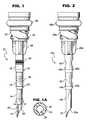
- FIG. 1is a side elevational view of a cannula constructed in accordance with a preferred embodiment of the present invention
- FIG. 1Ais a cross-sectional view thereof taken generally about on line 1 A— 1 A in FIG. 1;
- FIG. 2is a view similar to FIG. 1 illustrating a further form of the present innovation
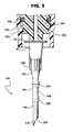
- FIG. 3is a fragmentary cross-sectional view of the cannula of FIG. 2 secured for use in the end of a syringe;
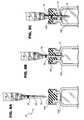
- FIG. 4is a fragmentary cross-sectional view of the end of a syringe with a cannula having a Luer fit poised for connection with the syringe;
- FIG. 5is a side elevational view of the cannula fit on the adapter of the syringe of FIG. 4;
- FIG. 6is a view similar to FIG. 4 illustrating the cannula poised for securement as a Luer lock with an adapter of a syringe;
- FIG. 7is a fragmentary perspective view illustrating a preferred interconnection between a syringe plunger and adapter mounting a cannula for withdrawing the cannula into the syringe barrel after use according to the present innovation
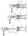
- FIGS. 8A, 8 B and 8 Care sequential views illustrating the cannula of FIG. 1 penetrating a non-pre-slit septum;
- FIGS. 9A, 9 B and 9 Cillustrate the cannula of FIG. 2 engaging through a non-pre-slit septum
- FIG. 10illustrates an IV set illustrating a syringe for penetration of a septum in the port of an IV line
- FIG. 11illustrates a syringe with the cannula retracted and sealed within the barrel after use
- FIG. 12is a view similar to FIG. 1 illustrating a further embodiment of a cannula
- FIG. 13is a fragmentary elevational view of a cannula body with transition sections capturing a membrane.
- a cannulagenerally designated 10 , preferably formed of a plastic material such as ABS or polycarbonate.
- the cannula 10may also be formed of carbon fiber or metal.
- Cannula 10includes a sleeve having a tip 12 at one end forming part of a piercing section 14 of the cannula.
- Piercing section 14has the smallest diameter of cannula 10 .
- a second section 16is axially spaced from section 14 and has an increased diameter.
- Section 18is axially spaced from both sections 14 and 16 and has a further increased diameter relative thereto.
- the sections 14 , 16 and 18are separated one from the other by transition sections 20 and 22 , respectively, which are tapered inwardly in the direction of penetration of the cannula 10 through a membrane or septum.
- the transition sections 20 and 22have slightly larger diameters than the diameters of the larger of the sections joined by the transition portions to provide a tactile feel when the cannula penetrates a septum and passes through the septum from one section to the next.
- the transition sections Xalso provide increased retention therein, i.e., increased resistance to withdrawal.
- cannula 10has its opposite end integrally formed as an adapter 24 for releasable securement to the distal end of a barrel as described hereinafter. Reinforcing struts 26 are provided about the circumference of the cannula 10 , reinforcing the connection between the smaller diameter cannula sections and the integral adapter 24 .
- the illustrated and described cannula 10comprises an elongated sleeve having a central axial passage 28 extending from the tip 12 throughout the length of the cannula 10 and through the adapter 24 for communication with the interior of a syringe barrel.
- the tip 12 of the cannula 10has at least one angled surface 30 , preferably about 20-45° relative to the cannula axis, through which the passage 28 opens.
- the piercing section 14is preferably smooth-sided, of narrow diameter, for example, on the order of 0.070 inches, and is preferably coated with a material to reduce the friction between the cannula and a membrane, e.g., a septum, as the cannula penetrates the membrane, whether the membrane is a non-pre-slit or pre-slit septum.
- the coating 32(FIG. 1A) may be any surface coating with a reduced coefficient of friction, as compared with the coefficient of friction of the base material, i.e., plastic.
- the coatingmay be silicone or Parylene. This coating facilitates penetration of the piercing section through a membrane.
- the coatingwhich may, for example, be Dow Corning MDX4-4159, may be applied throughout the length of the cannula or can be applied only to the piercing section 14 .
- the increased diameter second section 16 axially spaced from section 14 and tip 12preferably has a surface which affords increased frictional resistance to movement of the cannula relative to a membrane, e.g., a septum, beyond that which is afforded by its increase in diameter relative to the piercing section 14 .
- a coating or surface treatmentfor example, an EDM (Electrical Discharge Machining) finish, can be applied to section 16 to afford such increased friction.
- a plurality of discrete laterally extending, integrally formed projections 34are disposed on the section 16 . Projections 34 are spaced circumferentially and axially or randomly at different angles relative to one another along the length of and about section 16 . It will be appreciated that upon insertion of cannula 10 into the membrane sufficiently to locate section 16 in contact with the membrane, the projections 34 engage the registering walls of the membrane and increase the resistance to withdrawal of the cannula from the membrane.
- one or more outwardly projecting ribs 36are provided on section 18 .
- the ribsare preferably axially spaced one from the other along the cannula and may have arcuate or barbed surfaces in cross-section.
- the ribs 36may have arcuate semi-cylindrical surfaces.
- barbsmay be provided having tapered surfaces facing in either or both axial directions or tapered surfaces facing one axial direction with an opposite surface normal to the axis of the cannula.
- the ribsafford increased resistance to removal of the cannula from the membrane and permit the syringe mounting the cannula to be wholly supported by the frictional contact between ribs 36 and the penetrated walls of the membrane.
- both sections 16 and 18may have ribs, projections, EDM (Electrical Discharge Machining) or variable high grit surfaces or combinations of those surfaces.
- EDMElectro Discharge Machining
- transition portions 20 and 22provide tactile indication to the user of the extent of penetration of the cannula through the membrane and thus the user not only can visualize the depth of penetration of the cannula into the septum but can, by feel, recognize the depth of penetration.
- the transition portions 20 and 22as well as the projections 16 and ribs 36 , constitute stops which afford the user a tactile indication of the depth of penetration into the septum.
- Cannula 10 acomprises an elongated sleeve having a tip 12 a , sections 14 a , 16 a and 18 a of increasing diameter in an axial direction from the tip toward the opposite end of the cannula and tapered transition areas 20 a and 22 a between the respective sections.
- sections 16 a and 18 ahave relatively reduced diameter portions or waists 40 and 42 , respectively, intermediate their lengths.
- the cannula 10 aWhen the cannula 10 a is inserted into the membrane and one or the other of the waists registers with the membrane, the cannula tends to remain within the membrane rather than falling out when the cannula and attached syringe are freely supported by the cannula from the membrane.
- the waists 40 , 42can be used in conjunction with the projections and/or ribs as in FIG. 1 and/or textured surfaces.
- the proximal end of the cannula 10 or 10 ais integrally connected with the adapter 24 or 24 a as previously noted.
- Adapter 24has male threads 50 for threaded engagement with the female threads 52 along the inside surface of the distal end of the syringe barrel 54 .
- Proximally of the threads and on the adapter 24 , 24 ais an O-ring seal 56 , 56 a for sealing the adapter in the distal end of the syringe barrel 54 .
- the adapteris screwthreaded into and sealed relative to the distal end of the barrel and is releasable therefrom for retraction along with the cannula into the interior of the barrel.
- Retraction of the adapter and cannulamay be effected by any one of a number of different mechanisms.
- the mechanisms disclosed in U.S. Pat. No. 6,033,386 of common assignee herewith and incorporated herein by referencemay be used to withdraw the adapter of the cannula into the barrel.
- the adapter 24 , 24 aincludes a central recess 58 , the bottom of which has a central opening 60 in communication with the passage 28 of the cannula.
- the adapteralso includes within recess 58 plunger connective structure including alignment, drive and connective surfaces 62 , 64 and 66 , respectively.
- the alignment surfaces 62include arcuate sloping surfaces, while the drive surfaces 64 comprise radial and axially extending flat surfaces.
- the connective surfaces 66include radially inwardly projecting arcuate ribs or flanges spaced axially from the alignment and drive surfaces 62 and 64 , respectively, and circumferentially from one another.
- the distal end of the plunger 67is illustrated in FIG.
- the adapter 7includes a bung 68 and adapter connective structure including alignment surfaces 70 , drive surfaces 72 and connective surface 74 , generally complementary to the alignment, drive and connective surfaces 62 , 64 and 66 , respectively, of the adapter.
- the alignment surfaces 70 and 62engage one another to rotate the plunger and adapter relative to one another to bring the drive surfaces 64 and 72 into contact with one another.
- the ribs 66engage in the annular groove 74 of the plunger.
- the plungercan be broken off at a break-off location 76 and attached to the distal end of the barrel, sealing the barrel at that end.
- a rib 77 adjacent the finger press end 79 of the plunger 67seals with the interior surface of the distal end of the barrel (FIG. 11 ).
- the bung 68seals the barrel at its proximal end with the adapter and cannula within the interior of the barrel.
- the used cannulacan also be sealed within the barrel using the cap which, prior to use, was placed on the front of the barrel to protect the needle or cannula.
- FIG. 4wherein like parts have like reference numerals as in the preceding embodiments, followed by the suffix “b,” there is illustrated a cannula 10 b of the type illustrated in FIG. 2, except that the proximal end of the cannula carries a Luer fit or lock 80 .
- the Luer fit or lockcomprises a generally conical section having a conical recess opening through its larger diameter end at the proximal end of the cannula 10 b .
- the Luer fit or lock 80also includes radially extending, diametrically opposite flanges 82 .
- the cannula 10 bcan be readily applied to the syringe by pressing the female Luer conical section onto a complementary tapered male part 84 of the syringe. The frictional engagement between these parts maintains the cannula on the end of the adapter.
- the adapter 24 bis similar to adapter 24 in all respects except that adapter 24 b has the tapered male part 84 at its distal end in lieu of being integral with the cannula.
- FIG. 5illustrates the cannula 10 b of FIG. 4 fully secured to the adapter 24 b.
- FIG. 6there is illustrated a cannula of the type illustrated in FIG. 2 wherein like parts have like reference numerals, followed by the suffix “c.”
- the cannula 10 cis identical to the cannula 10 b and has a Luer lock 80 c with the end of the syringe.
- the adapter 24 c in FIG. 6includes an axially extending sleeve 90 which has internal female threads 92 surrounding the male Luer conical projection 94 .
- the Luer lock 80 cis rotated onto the male projection 94 such that flanges 82 c are threaded along the internal threads 92 , thus securing the cannula 10 c to the adapter 24 c.
- the septum 100may also be pre-slit.
- the piercing section 14 of cannula 10is first inserted into the non-pre-slit septum 100 . Because of the reduced friction afforded by coating 32 , entry of the cannula into the septum, particularly a non-pre-slit septum, is facilitated.
- the second section 16 as illustrated in FIG. 8Bis received within the vial 102 .
- the third section 18may be received within the vial 102 to afford further increased resistance to withdrawal of the cannula from the vial while assuring the sealing engagement therebetween.
- the vial and syringemay be inverted and medication withdrawn into the syringe in the usual manner with the assurance that the cannula and vial are in sealing engagement with one another and will not separate from one another.
- the transition portions 20 and 22indicate to the user in a tactile manner that the cannula is transitioning from the first section 14 to the second section 16 and subsequently from section 16 to section 18 .
- the cannula 10 ais illustrated penetrating a non-pre-slit membrane, for example, the stopper 110 on an evacuated container 112 .
- the piercing section 14With the piercing section 14 first piercing and entering the membrane 110 , the user can apply further pressure and engage in sequence the sections 16 and 18 of the cannula with the evacuated container. Consequently, it will be seen that the cannula can be used with both non-pre-slit and pre-slit septums. Also, the resistance to withdrawal of the cannula from the septum is a function of the depth of penetration of the cannula into the septum.
- an IV set 120containing a flexible IV bag 122 and a line 124 , the distal end of which is typically connected with a patient.
- Various ports 126are provided along the length of the IV line 124 for fluid injection, for example, by a syringe 128 .
- the ports 126typically have a pre-slit septum 130 at the Y-slit in the IV line 124 and which port 126 and septum 130 may be of various sizes. It is useful as explained previously for the IV set, including the septums in the ports, to frequently support the syringe 128 from a port, for example, in the case of titrating of a fluid and giving serial aliquots of medication.
- the cannula 10 hereofmay be used with the different physical dimensions and characteristics such as diameter and/or hardness and/or thickness of the septums currently in available IV and other ports.
- the different resistance to movement depending upon the depth of insertion of the cannula through the septumenables the present cannula to be used with such septums with the assurance that the cannula will not withdraw from the septum absent the user positively withdrawing the cannula.
- the cannulais inserted such that the intermediate section 16 frictionally contacts the septum.
- the projections 34 engaging the septumserve as an initial stop preventing the start of sliding withdrawing movement.
- the cannulacan be inserted such that the third section engages the pre-slit walls of the septum.
- the cannulacan be attached to the syringe and employed to penetrate the pre-slit or non-pre-slit septums of medication vials to withdraw the medication therefrom and supply the medication directly to the pre-slit septum in a portion of an IV line without any intervening additional devices.
- a cannula 10 chaving a body comprising an elongated sleeve having various sections 134 , 136 and 138 separated axially from one another by larger diameter transition sections 140 and 141 .
- the sections 134 , 136 and 138may be similar to sections 14 , 16 and 18 of the preceding embodiments, i.e., sections of increasing diameter in a direction away from the tip of the cannula, or may have identical diameters as illustrated in FIG. 12 .
- the transition sections 140 and 141may have different diameters relative to one another, the diameter of section 141 preferably being greater than the diameter of section 140 .
- transition sections 140 and 141along their forward surfaces 144 and 146 , respectively, facing tip 12 c are different.
- the surface 144slopes outwardly from the sleeve to a lesser extent than the sloped surface 146 .
- the surfaces 144 and 146thus offer different resistance to movement of the cannula body through the septum or membrane.
- the back or rear surfaces 148 and 150 of transition section 140 and 141are different from one another.
- the sloped surface 148offers less resistance to withdrawal of the cannula body from the septum or membrane than the surface 150 , which lies substantially at right angles to the axis of the cannula body.
- the resistance to axial movement of the cannula body through a septum or membrane in one directionmay therefore be different from the resistance to movement of the cannula body through the septum or membrane in the opposite direction. Also, there are differences in resistance to movement in any one direction.
- the illustrated transition sections 140 and 141afford differential, e.g., increasing resistance to movement in a direction of axial inserting movement of the cannula body through the membrane or septum into a vial, whereas movement of the cannula body relative to the membrane or septum in an opposite direction, e.g., withdrawing the cannula body from the vial capped by the membrane or septum, may provide a greater resistance to withdrawal than either transition section 140 or 141 affords upon insertion.
- the surfaces 148 and 150also provide differential resistance to movement in the opposite, i.e., withdrawing, direction relative to the septum or membrane.
- the shape of the surfaces 148 and 150 along the back sides of the transition sections 140 and 141 , respectively,can be altered to increase or decrease the resistance to movement of the cannula body through the membrane or septum. For example, a more gentle slope along the surfaces 148 and 150 of the transition sections 140 and 141 , respectively, affords less resistance than the illustrated relatively sharp slopes along the illustrated surfaces 148 and 150 .
- transition sections 140 and 141may have different resistances to movement of the cannula body relative to the membrane or septum in either direction and differential resistance to movement in any one direction depending upon the depth of penetration of the cannula body in the septum or membrane.
- the degree of resistance to movemente.g., either withdrawal or insertion, can be changed.
- the transition sections 140 and 141may be utilized with any of the preceding embodiments of the invention.
- the sleeve sections 134 , 136 and 138may comprise any of the sleeve sections 14 , 16 , 18 ; 14 a ; 16 a , 18 a ; 14 b , 16 b and 18 b ; and 14 c , 16 c and 18 c of the previous embodiments.
- transition sections in each of the embodiments hereofneed not comprise annular surfaces and may comprise segmented, circumferentially extending surfaces, e.g., as illustrated by the transition section segments 150 of FIG. 13 .
- Segmented surfacesfacilitate insertion and withdrawal of the cannula body relative to the membrane M.
- the cannula bodycan be canted or angled relative to the surface of the septum or membrane with the space between the segments first engaging the membrane, offering less resistance to movement of the cannula body relative to the membrane or septum.
- transition sections or ribsmay be provided on the cannula body at locations to capture and releasably lock the membrane or septum surface between the axially spaced transition sections.
- the opposing surfaces 152 and 154 (FIG. 13) of the transition sectionsmay comprise flat, annular surfaces slightly exceeding the thickness of the membrane M.
- the margins of the membrane or septum about the openingmay be captured between the right angularly related surfaces 152 and 154 of the transition sections. This affords substantial resistance to movement of the cannula body in either direction relative to the membrane or septum.
- the transition sectionscan be formed in a shape having a lateral dimension in one direction greater than a right angularly related lateral dimension.
- the transition sectioncan be in the form of an oval or even rectilinear, with orthogonally related long and short axes, as viewed axially.
- the long axis of the oval or rectilinear transition sectioncan be aligned in the direction of a slit in the membrane or septum, i.e., in registration with the slit, facilitating movement of the cannula body relative to the membrane or septum.
- alignment of the smaller dimension of the oval or rectilinear-shaped transition section in the direction of and in registration with the slit of the membrane or septumaffords increased resistance to movement of the cannula body relative to the membrane or septum.
- the alignmentcan be accomplished by rotating the cannula body relative to the membrane or septum to align or misalign alignment marks on the cannula body and the membrane or septum.
- the cannula body sleevemay have a cross-sectional configuration perpendicular to its axis different than cylindrical.
- the cannula body sleevemay have an oval or rectilinear, e.g., square, cross-sectional configuration, to afford additional surface area which further increases resistance to movement relative to a membrane or septum and also further inhibits or minimizes any tendency of the blunt cannula to penetrate an individual's skin or the rubber gloves used in surgical procedures.
Landscapes
- Health & Medical Sciences (AREA)
- Engineering & Computer Science (AREA)
- Heart & Thoracic Surgery (AREA)
- Vascular Medicine (AREA)
- Anesthesiology (AREA)
- Biomedical Technology (AREA)
- Hematology (AREA)
- Life Sciences & Earth Sciences (AREA)
- Animal Behavior & Ethology (AREA)
- General Health & Medical Sciences (AREA)
- Public Health (AREA)
- Veterinary Medicine (AREA)
- Environmental & Geological Engineering (AREA)
- Infusion, Injection, And Reservoir Apparatuses (AREA)
Abstract
Description
Claims (21)
Priority Applications (1)
| Application Number | Priority Date | Filing Date | Title |
|---|---|---|---|
| US10/152,981US6616632B2 (en) | 2000-06-09 | 2002-05-23 | Cannula for use with a medical syringe |
Applications Claiming Priority (2)
| Application Number | Priority Date | Filing Date | Title |
|---|---|---|---|
| US09/590,681US6394979B1 (en) | 2000-06-09 | 2000-06-09 | Cannula for use with a medical syringe |
| US10/152,981US6616632B2 (en) | 2000-06-09 | 2002-05-23 | Cannula for use with a medical syringe |
Related Parent Applications (1)
| Application Number | Title | Priority Date | Filing Date |
|---|---|---|---|
| US09/590,681Continuation-In-PartUS6394979B1 (en) | 2000-06-09 | 2000-06-09 | Cannula for use with a medical syringe |
Publications (2)
| Publication Number | Publication Date |
|---|---|
| US20020165504A1 US20020165504A1 (en) | 2002-11-07 |
| US6616632B2true US6616632B2 (en) | 2003-09-09 |
Family
ID=24363236
Family Applications (2)
| Application Number | Title | Priority Date | Filing Date |
|---|---|---|---|
| US09/590,681Expired - Fee RelatedUS6394979B1 (en) | 2000-06-09 | 2000-06-09 | Cannula for use with a medical syringe |
| US10/152,981Expired - LifetimeUS6616632B2 (en) | 2000-06-09 | 2002-05-23 | Cannula for use with a medical syringe |
Family Applications Before (1)
| Application Number | Title | Priority Date | Filing Date |
|---|---|---|---|
| US09/590,681Expired - Fee RelatedUS6394979B1 (en) | 2000-06-09 | 2000-06-09 | Cannula for use with a medical syringe |
Country Status (6)
| Country | Link |
|---|---|
| US (2) | US6394979B1 (en) |
| EP (1) | EP1409047A2 (en) |
| JP (1) | JP2003534877A (en) |
| AU (1) | AU2001270367A1 (en) |
| CA (1) | CA2411347A1 (en) |
| WO (1) | WO2001093923A2 (en) |
Cited By (92)
| Publication number | Priority date | Publication date | Assignee | Title |
|---|---|---|---|---|
| US20040030302A1 (en)* | 2001-03-28 | 2004-02-12 | Miyako Kamata | Medical syringe, and method of producing the same |
| US20060200095A1 (en)* | 2005-03-02 | 2006-09-07 | Steube Gregory A | Blunt tip vial access cannula |
| US20060287639A1 (en)* | 2005-06-15 | 2006-12-21 | Inviro Medical Devices Ltd. | Safety fluid transfer cannula |
| US20070282281A1 (en)* | 2006-05-19 | 2007-12-06 | Ide J W | Piercing tip |
| US20080065027A1 (en)* | 2004-09-16 | 2008-03-13 | Sharp Fraser R | Disposable Safety Syringe to Prevent Needlestick Injuries and Reuse |
| US20080195054A1 (en)* | 2007-02-08 | 2008-08-14 | Inviro Medical, Inc. | Safety cannula needle protector |
| US20090062607A1 (en)* | 2004-01-29 | 2009-03-05 | Cannuflow Incorporated | Atraumatic Arthroscopic Instrument Sheath |
| USD589617S1 (en)* | 2008-04-21 | 2009-03-31 | Tyco Healthcare Group Lp | Cannula assembly |
| USD589616S1 (en)* | 2008-04-21 | 2009-03-31 | Tyco Healthcare Group Lp | Cannula assembly |
| US20090099431A1 (en)* | 2006-06-21 | 2009-04-16 | Corey Dalebout | Bodily fluid sampling systems, methods, and devices |
| US7670328B2 (en) | 2002-05-31 | 2010-03-02 | Vidacare Corporation | Apparatus and method to provide emergency access to bone marrow |
| US20100160889A1 (en)* | 2008-12-22 | 2010-06-24 | Baxter International Inc. | Vial access spike assembly |
| US7811260B2 (en) | 2002-05-31 | 2010-10-12 | Vidacare Corporation | Apparatus and method to inject fluids into bone marrow and other target sites |
| US7815642B2 (en) | 2004-01-26 | 2010-10-19 | Vidacare Corporation | Impact-driven intraosseous needle |
| US7850620B2 (en) | 2002-05-31 | 2010-12-14 | Vidacare Corporation | Biopsy devices and related methods |
| US20110028795A1 (en)* | 2009-07-29 | 2011-02-03 | Tyco Healthcare Group Lp | Surgical portal device including textured surface |
| US7951089B2 (en) | 2002-05-31 | 2011-05-31 | Vidacare Corporation | Apparatus and methods to harvest bone and bone marrow |
| US20120016213A1 (en)* | 2010-07-15 | 2012-01-19 | Becton, Dickinson And Company | Blood test strip and an intravenous catheter system |
| US8142365B2 (en) | 2002-05-31 | 2012-03-27 | Vidacare Corporation | Apparatus and method for accessing the bone marrow of the sternum |
| US8216156B2 (en) | 2006-06-21 | 2012-07-10 | Glucor Systems, Llc | Systems, methods, and devices for sampling bodily fluid |
| US8419683B2 (en) | 2004-11-12 | 2013-04-16 | Vidacare Corporation | Intraosseous device and methods for accessing bone marrow in the sternum and other target areas |
| USD680647S1 (en) | 2008-04-21 | 2013-04-23 | Covidien Lp | Cannula assembly |
| US8496574B2 (en) | 2009-12-17 | 2013-07-30 | Ethicon Endo-Surgery, Inc. | Selectively positionable camera for surgical guide tube assembly |
| US8506564B2 (en) | 2009-12-18 | 2013-08-13 | Ethicon Endo-Surgery, Inc. | Surgical instrument comprising an electrode |
| US8512796B2 (en) | 2009-05-13 | 2013-08-20 | Si02 Medical Products, Inc. | Vessel inspection apparatus and methods |
| US8579897B2 (en) | 2007-11-21 | 2013-11-12 | Ethicon Endo-Surgery, Inc. | Bipolar forceps |
| US8608652B2 (en) | 2009-11-05 | 2013-12-17 | Ethicon Endo-Surgery, Inc. | Vaginal entry surgical devices, kit, system, and method |
| US8641715B2 (en) | 2002-05-31 | 2014-02-04 | Vidacare Corporation | Manual intraosseous device |
| US8656929B2 (en) | 2002-05-31 | 2014-02-25 | Vidacare Corporation | Medical procedures trays and related methods |
| US8668698B2 (en) | 2002-05-31 | 2014-03-11 | Vidacare Corporation | Assembly for coupling powered driver with intraosseous device |
| US8690791B2 (en) | 2002-05-31 | 2014-04-08 | Vidacare Corporation | Apparatus and method to access the bone marrow |
| US8771260B2 (en) | 2008-05-30 | 2014-07-08 | Ethicon Endo-Surgery, Inc. | Actuating and articulating surgical device |
| USD717947S1 (en)* | 2012-07-13 | 2014-11-18 | Carmel Pharma Ab | Spike for medical vial access device |
| US8906035B2 (en) | 2008-06-04 | 2014-12-09 | Ethicon Endo-Surgery, Inc. | Endoscopic drop off bag |
| US8939897B2 (en) | 2007-10-31 | 2015-01-27 | Ethicon Endo-Surgery, Inc. | Methods for closing a gastrotomy |
| US8944069B2 (en) | 2006-09-12 | 2015-02-03 | Vidacare Corporation | Assemblies for coupling intraosseous (IO) devices to powered drivers |
| US8974410B2 (en) | 2006-10-30 | 2015-03-10 | Vidacare LLC | Apparatus and methods to communicate fluids and/or support intraosseous devices |
| US9005198B2 (en) | 2010-01-29 | 2015-04-14 | Ethicon Endo-Surgery, Inc. | Surgical instrument comprising an electrode |
| US9011431B2 (en) | 2009-01-12 | 2015-04-21 | Ethicon Endo-Surgery, Inc. | Electrical ablation devices |
| US9028483B2 (en) | 2009-12-18 | 2015-05-12 | Ethicon Endo-Surgery, Inc. | Surgical instrument comprising an electrode |
| US9072543B2 (en) | 2002-05-31 | 2015-07-07 | Vidacare LLC | Vascular access kits and methods |
| US9078662B2 (en) | 2012-07-03 | 2015-07-14 | Ethicon Endo-Surgery, Inc. | Endoscopic cap electrode and method for using the same |
| US9125992B2 (en) | 2011-09-16 | 2015-09-08 | Melvin A. Finke | Fluid delivery device with filtration |
| US9220526B2 (en) | 2008-11-25 | 2015-12-29 | Ethicon Endo-Surgery, Inc. | Rotational coupling device for surgical instrument with flexible actuators |
| US9233241B2 (en) | 2011-02-28 | 2016-01-12 | Ethicon Endo-Surgery, Inc. | Electrical ablation devices and methods |
| US9254169B2 (en) | 2011-02-28 | 2016-02-09 | Ethicon Endo-Surgery, Inc. | Electrical ablation devices and methods |
| US9272095B2 (en) | 2011-04-01 | 2016-03-01 | Sio2 Medical Products, Inc. | Vessels, contact surfaces, and coating and inspection apparatus and methods |
| US9277957B2 (en) | 2012-08-15 | 2016-03-08 | Ethicon Endo-Surgery, Inc. | Electrosurgical devices and methods |
| US9314228B2 (en) | 2002-05-31 | 2016-04-19 | Vidacare LLC | Apparatus and method for accessing the bone marrow |
| US9314620B2 (en) | 2011-02-28 | 2016-04-19 | Ethicon Endo-Surgery, Inc. | Electrical ablation devices and methods |
| US9375268B2 (en) | 2007-02-15 | 2016-06-28 | Ethicon Endo-Surgery, Inc. | Electroporation ablation apparatus, system, and method |
| US9427255B2 (en) | 2012-05-14 | 2016-08-30 | Ethicon Endo-Surgery, Inc. | Apparatus for introducing a steerable camera assembly into a patient |
| US9433400B2 (en) | 2004-01-26 | 2016-09-06 | Vidacare LLC | Manual intraosseous device |
| US9439667B2 (en) | 2002-05-31 | 2016-09-13 | Vidacare LLC | Apparatus and methods to install, support and/or monitor performance of intraosseous devices |
| US9451968B2 (en) | 2002-05-31 | 2016-09-27 | Vidacare LLC | Powered drivers, intraosseous devices and methods to access bone marrow |
| US9458536B2 (en) | 2009-07-02 | 2016-10-04 | Sio2 Medical Products, Inc. | PECVD coating methods for capped syringes, cartridges and other articles |
| US9504477B2 (en) | 2003-05-30 | 2016-11-29 | Vidacare LLC | Powered driver |
| US9510910B2 (en) | 2006-09-12 | 2016-12-06 | Vidacare LLC | Medical procedures trays and related methods |
| US9545290B2 (en) | 2012-07-30 | 2017-01-17 | Ethicon Endo-Surgery, Inc. | Needle probe guide |
| US9545360B2 (en) | 2009-05-13 | 2017-01-17 | Sio2 Medical Products, Inc. | Saccharide protective coating for pharmaceutical package |
| US9545243B2 (en) | 2002-05-31 | 2017-01-17 | Vidacare LLC | Bone marrow aspiration devices and related methods |
| US9554968B2 (en) | 2013-03-11 | 2017-01-31 | Sio2 Medical Products, Inc. | Trilayer coated pharmaceutical packaging |
| US9572623B2 (en) | 2012-08-02 | 2017-02-21 | Ethicon Endo-Surgery, Inc. | Reusable electrode and disposable sheath |
| US9664626B2 (en) | 2012-11-01 | 2017-05-30 | Sio2 Medical Products, Inc. | Coating inspection method |
| US9662450B2 (en) | 2013-03-01 | 2017-05-30 | Sio2 Medical Products, Inc. | Plasma or CVD pre-treatment for lubricated pharmaceutical package, coating process and apparatus |
| US9750891B1 (en) | 2009-11-17 | 2017-09-05 | Moshe Mike Hoftman | Device for safe withdrawal and administration of liquids by syringe |
| US9764093B2 (en) | 2012-11-30 | 2017-09-19 | Sio2 Medical Products, Inc. | Controlling the uniformity of PECVD deposition |
| US9863042B2 (en) | 2013-03-15 | 2018-01-09 | Sio2 Medical Products, Inc. | PECVD lubricity vessel coating, coating process and apparatus providing different power levels in two phases |
| US9878101B2 (en) | 2010-11-12 | 2018-01-30 | Sio2 Medical Products, Inc. | Cyclic olefin polymer vessels and vessel coating methods |
| US9883910B2 (en) | 2011-03-17 | 2018-02-06 | Eticon Endo-Surgery, Inc. | Hand held surgical device for manipulating an internal magnet assembly within a patient |
| US9903782B2 (en) | 2012-11-16 | 2018-02-27 | Sio2 Medical Products, Inc. | Method and apparatus for detecting rapid barrier coating integrity characteristics |
| US9937099B2 (en) | 2013-03-11 | 2018-04-10 | Sio2 Medical Products, Inc. | Trilayer coated pharmaceutical packaging with low oxygen transmission rate |
| US10092291B2 (en) | 2011-01-25 | 2018-10-09 | Ethicon Endo-Surgery, Inc. | Surgical instrument with selectively rigidizable features |
| USD831200S1 (en) | 2016-08-08 | 2018-10-16 | Ultradent Products, Inc. | Delivery tip |
| US10098527B2 (en) | 2013-02-27 | 2018-10-16 | Ethidcon Endo-Surgery, Inc. | System for performing a minimally invasive surgical procedure |
| US10105141B2 (en) | 2008-07-14 | 2018-10-23 | Ethicon Endo-Surgery, Inc. | Tissue apposition clip application methods |
| US10189603B2 (en) | 2011-11-11 | 2019-01-29 | Sio2 Medical Products, Inc. | Passivation, pH protective or lubricity coating for pharmaceutical package, coating process and apparatus |
| US10201660B2 (en) | 2012-11-30 | 2019-02-12 | Sio2 Medical Products, Inc. | Controlling the uniformity of PECVD deposition on medical syringes, cartridges, and the like |
| US10314649B2 (en) | 2012-08-02 | 2019-06-11 | Ethicon Endo-Surgery, Inc. | Flexible expandable electrode and method of intraluminal delivery of pulsed power |
| US10779882B2 (en) | 2009-10-28 | 2020-09-22 | Ethicon Endo-Surgery, Inc. | Electrical ablation devices |
| US10905462B2 (en) | 2017-08-15 | 2021-02-02 | Alcon Inc. | Ophthalmic cannula and retaining feature therefor |
| US10973545B2 (en) | 2002-05-31 | 2021-04-13 | Teleflex Life Sciences Limited | Powered drivers, intraosseous devices and methods to access bone marrow |
| US10973532B2 (en) | 2002-05-31 | 2021-04-13 | Teleflex Life Sciences Limited | Powered drivers, intraosseous devices and methods to access bone marrow |
| US11066745B2 (en) | 2014-03-28 | 2021-07-20 | Sio2 Medical Products, Inc. | Antistatic coatings for plastic vessels |
| US11077233B2 (en) | 2015-08-18 | 2021-08-03 | Sio2 Medical Products, Inc. | Pharmaceutical and other packaging with low oxygen transmission rate |
| US11116695B2 (en) | 2011-11-11 | 2021-09-14 | Sio2 Medical Products, Inc. | Blood sample collection tube |
| US11298202B2 (en) | 2002-05-31 | 2022-04-12 | Teleflex Life Sciences Limited | Biopsy devices and related methods |
| US11337728B2 (en) | 2002-05-31 | 2022-05-24 | Teleflex Life Sciences Limited | Powered drivers, intraosseous devices and methods to access bone marrow |
| US11559464B2 (en) | 2016-05-16 | 2023-01-24 | Haemonetics Corporation | Sealer-less plasma bottle and top for same |
| US11624115B2 (en) | 2010-05-12 | 2023-04-11 | Sio2 Medical Products, Inc. | Syringe with PECVD lubrication |
| US11648179B2 (en) | 2016-05-16 | 2023-05-16 | Haemonetics Corporation | Sealer-less plasma bottle and top for same |
| US12257371B2 (en) | 2012-07-03 | 2025-03-25 | Sio2 Medical Products, Llc | SiOx barrier for pharmaceutical package and coating process |
Families Citing this family (50)
| Publication number | Priority date | Publication date | Assignee | Title |
|---|---|---|---|---|
| US9603741B2 (en) | 2000-05-19 | 2017-03-28 | Michael S. Berlin | Delivery system and method of use for the eye |
| US20040254541A1 (en)* | 2003-04-21 | 2004-12-16 | K. C. Wong | Non-sharp vascular infusion cannula |
| US20050075612A1 (en)* | 2003-10-03 | 2005-04-07 | Baxter International Inc. | Parylene coated fluid flow regulator |
| IN2014MN00187A (en)* | 2003-10-30 | 2015-08-21 | Teva Medical Ltd | |
| US20060079848A1 (en)* | 2004-06-29 | 2006-04-13 | Becton, Dickinson And Company | Non-skin penetrating reconstituting syringe |
| US7615041B2 (en)* | 2004-07-29 | 2009-11-10 | Boston Scientific Scimed, Inc. | Vial adaptor |
| FR2877580B1 (en)* | 2004-11-10 | 2009-11-06 | Gambro Lundia Ab | PLASTIC CANNULA |
| US20060204535A1 (en)* | 2005-02-25 | 2006-09-14 | Johnson Johnnie M | Cell-friendly cannula and needle |
| US20070179454A1 (en)* | 2006-01-31 | 2007-08-02 | Smiths Medical Asd, Inc. | Safety needle assembly with correct medication connection |
| JP2009534148A (en)* | 2006-04-26 | 2009-09-24 | ノボ・ノルデイスク・エー/エス | Cannula for infusion device having tapered end and method for manufacturing the cannula |
| WO2008057361A2 (en)* | 2006-11-02 | 2008-05-15 | Inviro Medical Devices, Ltd. | Interchangeable retractable needle syringe with safety filling cannula |
| US8425449B2 (en) | 2009-07-09 | 2013-04-23 | Ivantis, Inc. | Ocular implants and methods for delivering ocular implants into the eye |
| US8734377B2 (en) | 2007-09-24 | 2014-05-27 | Ivantis, Inc. | Ocular implants with asymmetric flexibility |
| US20170360609A9 (en) | 2007-09-24 | 2017-12-21 | Ivantis, Inc. | Methods and devices for increasing aqueous humor outflow |
| US20090082862A1 (en) | 2007-09-24 | 2009-03-26 | Schieber Andrew T | Ocular Implant Architectures |
| US8808222B2 (en) | 2007-11-20 | 2014-08-19 | Ivantis, Inc. | Methods and apparatus for delivering ocular implants into the eye |
| US20090143746A1 (en)* | 2007-11-30 | 2009-06-04 | Mudd Christopher S | Luer connectors, components thereof and fluent material delivery devices utilizing the same |
| JP2011513002A (en) | 2008-03-05 | 2011-04-28 | イバンティス インコーポレイテッド | Method and apparatus for treating glaucoma |
| US7981089B2 (en)* | 2008-03-31 | 2011-07-19 | Tyco Healthcare Group Lp | Vial access device |
| US8382722B2 (en) | 2008-06-30 | 2013-02-26 | Covidien Lp | Blunt tip vial access cannula and method for manufacture |
| US20100010298A1 (en)* | 2008-07-14 | 2010-01-14 | Ethicon Endo-Surgery, Inc. | Endoscopic translumenal flexible overtube |
| BRPI0917035A2 (en) | 2008-12-04 | 2019-09-24 | Pivot Medical Inc | "telescope access cannula, telescope shutter, system, method for providing an access corridor from a first off-site location to a second on-site location" |
| WO2010126076A1 (en)* | 2009-04-30 | 2010-11-04 | マニー株式会社 | Cannula for ophthalmic surgery and method of manufacturing same |
| AU2010271274B2 (en) | 2009-07-09 | 2015-05-21 | Alcon Inc. | Single operator device for delivering an ocular implant |
| CN102647960A (en) | 2009-10-23 | 2012-08-22 | 伊万提斯公司 | Ocular implant system and method |
| US9510973B2 (en) | 2010-06-23 | 2016-12-06 | Ivantis, Inc. | Ocular implants deployed in schlemm's canal of the eye |
| US10076272B2 (en) | 2011-04-26 | 2018-09-18 | Velano Vascular, Inc. | Systems and methods for phlebotomy through a peripheral IV catheter |
| US8366685B2 (en)* | 2011-04-26 | 2013-02-05 | Creative Vascular, Llc | Systems and methods for phlebotomy through a peripheral IV catheter |
| US8657776B2 (en) | 2011-06-14 | 2014-02-25 | Ivantis, Inc. | Ocular implants for delivery into the eye |
| US8945087B2 (en)* | 2011-09-30 | 2015-02-03 | Covidien Lp | Pre-pierced IV access port |
| US8663150B2 (en) | 2011-12-19 | 2014-03-04 | Ivantis, Inc. | Delivering ocular implants into the eye |
| US9358156B2 (en) | 2012-04-18 | 2016-06-07 | Invantis, Inc. | Ocular implants for delivery into an anterior chamber of the eye |
| US10617558B2 (en) | 2012-11-28 | 2020-04-14 | Ivantis, Inc. | Apparatus for delivering ocular implants into an anterior chamber of the eye |
| US20150250459A1 (en)* | 2014-03-04 | 2015-09-10 | BP II Technologeis | Carbon Fiber Medical Instrument |
| WO2016011056A1 (en) | 2014-07-14 | 2016-01-21 | Ivantis, Inc. | Ocular implant delivery system and method |
| KR20170102918A (en)* | 2015-01-02 | 2017-09-12 | 비그메드 아베 | Needle hub and iv catheter system comprising such needle hub |
| US11278664B2 (en) | 2015-01-09 | 2022-03-22 | Becton Dickinson and Company Limited | Infusion adapter |
| AU2016307951B2 (en) | 2015-08-14 | 2021-04-01 | Alcon Inc. | Ocular implant with pressure sensor and delivery system |
| RU2723534C2 (en)* | 2015-11-30 | 2020-06-15 | Мани, Инк. | Cannula provided with piercing needle |
| WO2017106517A1 (en) | 2015-12-15 | 2017-06-22 | Ivantis, Inc. | Ocular implant and delivery system |
| US10022531B2 (en) | 2016-01-21 | 2018-07-17 | Teva Medical Ltd. | Luer lock adaptor |
| US10092317B2 (en)* | 2016-01-22 | 2018-10-09 | Lsi Solutions, Inc. | Thoracic cannula, obturator, and assembly thereof |
| US10773056B2 (en) | 2017-03-21 | 2020-09-15 | Velano Vascular, Inc. | Systems and methods for controlling catheter device size |
| KR102573751B1 (en) | 2017-03-21 | 2023-09-04 | 벨라노 바스큘라, 인크. | Devices and methods for fluid delivery through a deployed peripheral intravenous catheter |
| CA3207829A1 (en) | 2018-02-22 | 2019-08-29 | Alcon Inc. | Ocular implant and delivery system |
| US11266779B2 (en)* | 2019-03-04 | 2022-03-08 | Carefusion 303, Inc. | IV set spike with enhanced removal force |
| CN119185741A (en) | 2019-08-20 | 2024-12-27 | 威蓝诺血管股份有限公司 | Fluid delivery device with elongate conduit and method of use thereof |
| US11690787B2 (en) | 2020-08-25 | 2023-07-04 | Becton, Dickinson And Company | Drug transfer adapter |
| US11540940B2 (en) | 2021-01-11 | 2023-01-03 | Alcon Inc. | Systems and methods for viscoelastic delivery |
| CN113289154B (en)* | 2021-06-28 | 2022-06-17 | 昆山爱希斯顿智能制造有限公司 | Blunt end injection needle for injection beauty |
Citations (22)
| Publication number | Priority date | Publication date | Assignee | Title |
|---|---|---|---|---|
| US2187259A (en) | 1936-07-11 | 1940-01-16 | George E Barnhart | Hypodermic needle |
| DE1491866A1 (en) | 1966-05-15 | 1969-10-09 | Injecta Klingenthal Klingentha | Hollow needle |
| DE2544109A1 (en) | 1975-10-02 | 1977-04-14 | Hoffmann Klaus | Intraoperative gall product removal cannula - has tapered sectional construction with longitudinal paired reinforcement ribs |
| US4735612A (en) | 1986-09-03 | 1988-04-05 | Ballistivet, Inc. | Trauma minimizing dart |
| US4861341A (en) | 1988-07-18 | 1989-08-29 | Woodburn Robert T | Subcutaneous venous access device and needle system |
| US4869259A (en) | 1988-05-17 | 1989-09-26 | Vance Products Incorporated | Echogenically enhanced surgical instrument and method for production thereof |
| WO1990011103A2 (en) | 1989-03-17 | 1990-10-04 | Baxter International Inc. | Pre-slit injection site and tapered cannula |
| US5071413A (en) | 1990-06-13 | 1991-12-10 | Utterberg David S | Universal connector |
| US5100394A (en) | 1988-01-25 | 1992-03-31 | Baxter International Inc. | Pre-slit injection site |
| US5158084A (en) | 1989-11-22 | 1992-10-27 | Board Of Regents, The University Of Texas System | Modified localization wire for excisional biopsy |
| US5199441A (en) | 1991-08-20 | 1993-04-06 | Hogle Hugh H | Fine needle aspiration biopsy apparatus and method |
| US5364373A (en) | 1990-11-05 | 1994-11-15 | Te Me Na Logistics | Epidural cannula |
| US5409004A (en) | 1993-06-11 | 1995-04-25 | Cook Incorporated | Localization device with radiopaque markings |
| US5484423A (en) | 1990-11-05 | 1996-01-16 | Te Me Na Logistics | Needle, for example epidural needle |
| EP0819443A2 (en) | 1996-07-17 | 1998-01-21 | Becton, Dickinson and Company | Hypodermic needle having a differential outside surface finish |
| US5752969A (en) | 1993-06-17 | 1998-05-19 | Sofamor S.N.C. | Instrument for the surgical treatment of an intervertebral disc by the anterior route |
| FR2758462A1 (en) | 1997-01-23 | 1998-07-24 | Gilles Bovyn | Injection or sampling syringe |
| US5797897A (en) | 1988-01-25 | 1998-08-25 | Baxter International Inc. | Pre-slit injection site and tapered cannula |
| US5993411A (en) | 1998-08-18 | 1999-11-30 | Choi; Soo Bong | Portable automatic syringe device and injection needle unit thereof |
| US6010486A (en) | 1998-12-18 | 2000-01-04 | Becton Dickinson And Company | Retracting needle syringe |
| US6033386A (en) | 1988-12-14 | 2000-03-07 | Inviro Medical Devices, Ltd. | Safety syringe needle device with interchangeable and retractable needle platform |
| US6224608B1 (en) | 1990-08-10 | 2001-05-01 | United States Surgical Corporation | Tissue holding device and method |
- 2000
- 2000-06-09USUS09/590,681patent/US6394979B1/ennot_activeExpired - Fee Related
- 2001
- 2001-06-08CACA002411347Apatent/CA2411347A1/ennot_activeAbandoned
- 2001-06-08AUAU2001270367Apatent/AU2001270367A1/ennot_activeAbandoned
- 2001-06-08JPJP2002501494Apatent/JP2003534877A/ennot_activeWithdrawn
- 2001-06-08EPEP01949121Apatent/EP1409047A2/ennot_activeWithdrawn
- 2001-06-08WOPCT/CA2001/000864patent/WO2001093923A2/enactiveApplication Filing
- 2002
- 2002-05-23USUS10/152,981patent/US6616632B2/ennot_activeExpired - Lifetime
Patent Citations (22)
| Publication number | Priority date | Publication date | Assignee | Title |
|---|---|---|---|---|
| US2187259A (en) | 1936-07-11 | 1940-01-16 | George E Barnhart | Hypodermic needle |
| DE1491866A1 (en) | 1966-05-15 | 1969-10-09 | Injecta Klingenthal Klingentha | Hollow needle |
| DE2544109A1 (en) | 1975-10-02 | 1977-04-14 | Hoffmann Klaus | Intraoperative gall product removal cannula - has tapered sectional construction with longitudinal paired reinforcement ribs |
| US4735612A (en) | 1986-09-03 | 1988-04-05 | Ballistivet, Inc. | Trauma minimizing dart |
| US5797897A (en) | 1988-01-25 | 1998-08-25 | Baxter International Inc. | Pre-slit injection site and tapered cannula |
| US5100394A (en) | 1988-01-25 | 1992-03-31 | Baxter International Inc. | Pre-slit injection site |
| US4869259A (en) | 1988-05-17 | 1989-09-26 | Vance Products Incorporated | Echogenically enhanced surgical instrument and method for production thereof |
| US4861341A (en) | 1988-07-18 | 1989-08-29 | Woodburn Robert T | Subcutaneous venous access device and needle system |
| US6033386A (en) | 1988-12-14 | 2000-03-07 | Inviro Medical Devices, Ltd. | Safety syringe needle device with interchangeable and retractable needle platform |
| WO1990011103A2 (en) | 1989-03-17 | 1990-10-04 | Baxter International Inc. | Pre-slit injection site and tapered cannula |
| US5158084A (en) | 1989-11-22 | 1992-10-27 | Board Of Regents, The University Of Texas System | Modified localization wire for excisional biopsy |
| US5071413A (en) | 1990-06-13 | 1991-12-10 | Utterberg David S | Universal connector |
| US6224608B1 (en) | 1990-08-10 | 2001-05-01 | United States Surgical Corporation | Tissue holding device and method |
| US5364373A (en) | 1990-11-05 | 1994-11-15 | Te Me Na Logistics | Epidural cannula |
| US5484423A (en) | 1990-11-05 | 1996-01-16 | Te Me Na Logistics | Needle, for example epidural needle |
| US5199441A (en) | 1991-08-20 | 1993-04-06 | Hogle Hugh H | Fine needle aspiration biopsy apparatus and method |
| US5409004A (en) | 1993-06-11 | 1995-04-25 | Cook Incorporated | Localization device with radiopaque markings |
| US5752969A (en) | 1993-06-17 | 1998-05-19 | Sofamor S.N.C. | Instrument for the surgical treatment of an intervertebral disc by the anterior route |
| EP0819443A2 (en) | 1996-07-17 | 1998-01-21 | Becton, Dickinson and Company | Hypodermic needle having a differential outside surface finish |
| FR2758462A1 (en) | 1997-01-23 | 1998-07-24 | Gilles Bovyn | Injection or sampling syringe |
| US5993411A (en) | 1998-08-18 | 1999-11-30 | Choi; Soo Bong | Portable automatic syringe device and injection needle unit thereof |
| US6010486A (en) | 1998-12-18 | 2000-01-04 | Becton Dickinson And Company | Retracting needle syringe |
Cited By (174)
| Publication number | Priority date | Publication date | Assignee | Title |
|---|---|---|---|---|
| US20040030302A1 (en)* | 2001-03-28 | 2004-02-12 | Miyako Kamata | Medical syringe, and method of producing the same |
| US8308693B2 (en) | 2002-05-31 | 2012-11-13 | Vidacare Corporation | Bone penetrating needle with angled ports |
| US10512474B2 (en) | 2002-05-31 | 2019-12-24 | Teleflex Medical Devices S.À R.L. | Powered drivers, intraosseous devices and methods to access bone marrow |
| US9717847B2 (en) | 2002-05-31 | 2017-08-01 | Teleflex Medical Devices S.Àr.L. | Apparatus and method to inject fluids into bone marrow and other target sites |
| US11324521B2 (en) | 2002-05-31 | 2022-05-10 | Teleflex Life Sciences Limited | Apparatus and method to access bone marrow |
| US11337728B2 (en) | 2002-05-31 | 2022-05-24 | Teleflex Life Sciences Limited | Powered drivers, intraosseous devices and methods to access bone marrow |
| US11234683B2 (en) | 2002-05-31 | 2022-02-01 | Teleflex Life Sciences Limited | Assembly for coupling powered driver with intraosseous device |
| US9545243B2 (en) | 2002-05-31 | 2017-01-17 | Vidacare LLC | Bone marrow aspiration devices and related methods |
| US9872703B2 (en) | 2002-05-31 | 2018-01-23 | Teleflex Medical Devices S.Àr.L. | Vascular access kits and methods |
| US10893875B2 (en) | 2002-05-31 | 2021-01-19 | Teleflex Life Sciences Limited | Apparatus to access bone marrow |
| US11103281B2 (en) | 2002-05-31 | 2021-08-31 | Teleflex Life Sciences Limited | Apparatus and methods to install, support and/or monitor performance of intraosseous devices |
| US7670328B2 (en) | 2002-05-31 | 2010-03-02 | Vidacare Corporation | Apparatus and method to provide emergency access to bone marrow |
| US7699850B2 (en) | 2002-05-31 | 2010-04-20 | Vidacare Corporation | Apparatus and method to access bone marrow |
| US9314270B2 (en) | 2002-05-31 | 2016-04-19 | Vidacare LLC | Apparatus and method to access bone marrow |
| US7811260B2 (en) | 2002-05-31 | 2010-10-12 | Vidacare Corporation | Apparatus and method to inject fluids into bone marrow and other target sites |
| US9451968B2 (en) | 2002-05-31 | 2016-09-27 | Vidacare LLC | Powered drivers, intraosseous devices and methods to access bone marrow |
| US7850620B2 (en) | 2002-05-31 | 2010-12-14 | Vidacare Corporation | Biopsy devices and related methods |
| US9439667B2 (en) | 2002-05-31 | 2016-09-13 | Vidacare LLC | Apparatus and methods to install, support and/or monitor performance of intraosseous devices |
| US7951089B2 (en) | 2002-05-31 | 2011-05-31 | Vidacare Corporation | Apparatus and methods to harvest bone and bone marrow |
| US8038664B2 (en) | 2002-05-31 | 2011-10-18 | Vidacare Corporation | Apparatus and method to inject fluids into bone marrow and other target sites |
| US10456149B2 (en) | 2002-05-31 | 2019-10-29 | Teleflex Medical Devices S.À R.L. | Apparatus and method to access bone marrow |
| US8142365B2 (en) | 2002-05-31 | 2012-03-27 | Vidacare Corporation | Apparatus and method for accessing the bone marrow of the sternum |
| US10016217B2 (en) | 2002-05-31 | 2018-07-10 | Teleflex Medical Devices S.À.R.L. | Apparatus and methods to install, support and/or monitor performance of intraosseous devices |
| US9393031B2 (en) | 2002-05-31 | 2016-07-19 | Vidacare LLC | Apparatus and method to provide emergency access to bone marrow |
| US11103282B1 (en) | 2002-05-31 | 2021-08-31 | Teleflex Life Sciences Limited | Powered drivers, intraosseous devices and methods to access bone marrow |
| US11266441B2 (en) | 2002-05-31 | 2022-03-08 | Teleflex Life Sciences Limited | Penetrator assembly for accessing bone marrow |
| US9314228B2 (en) | 2002-05-31 | 2016-04-19 | Vidacare LLC | Apparatus and method for accessing the bone marrow |
| US10492830B2 (en) | 2002-05-31 | 2019-12-03 | Teleflex Medical Devices S.À R.L. | Penetrator assembly for accessing bone marrow |
| US9295487B2 (en) | 2002-05-31 | 2016-03-29 | Vidacare LLC | Apparatus and method to inject fluids into bone marrow and other target sites |
| US8480632B2 (en) | 2002-05-31 | 2013-07-09 | Vidacare Corporation | Cartridge apparatus for injecting fluids into bone |
| US10413282B2 (en) | 2002-05-31 | 2019-09-17 | Teleflex Medical Devices S.Àr.L. | Apparatus and methods to harvest bone and bone marrow |
| US11298202B2 (en) | 2002-05-31 | 2022-04-12 | Teleflex Life Sciences Limited | Biopsy devices and related methods |
| US8506568B2 (en) | 2002-05-31 | 2013-08-13 | Vidacare Corporation | Apparatus and method to access bone marrow |
| US10595896B2 (en) | 2002-05-31 | 2020-03-24 | Teleflex Life Sciences Limited | Apparatus for accessing bone marrow including depth control mechanism |
| US10973545B2 (en) | 2002-05-31 | 2021-04-13 | Teleflex Life Sciences Limited | Powered drivers, intraosseous devices and methods to access bone marrow |
| US11065382B2 (en) | 2002-05-31 | 2021-07-20 | Teleflex Life Sciences Limited | Apparatus to inject fluids into bone marrow and other target sites |
| US10973532B2 (en) | 2002-05-31 | 2021-04-13 | Teleflex Life Sciences Limited | Powered drivers, intraosseous devices and methods to access bone marrow |
| US8641715B2 (en) | 2002-05-31 | 2014-02-04 | Vidacare Corporation | Manual intraosseous device |
| US8656929B2 (en) | 2002-05-31 | 2014-02-25 | Vidacare Corporation | Medical procedures trays and related methods |
| US8668698B2 (en) | 2002-05-31 | 2014-03-11 | Vidacare Corporation | Assembly for coupling powered driver with intraosseous device |
| US8684978B2 (en) | 2002-05-31 | 2014-04-01 | Vidacare Corporation | Apparatus and method to inject fluids into bone marrow and other target sites |
| US8690791B2 (en) | 2002-05-31 | 2014-04-08 | Vidacare Corporation | Apparatus and method to access the bone marrow |
| US8715287B2 (en) | 2002-05-31 | 2014-05-06 | Vidacare Corporation | Apparatus and method to provide emergency access to bone marrow |
| US10245010B2 (en) | 2002-05-31 | 2019-04-02 | Teleflex Medical Devices S.A.R.L | Assembly for coupling powered driver with intraosseous device |
| US8992535B2 (en) | 2002-05-31 | 2015-03-31 | Vidacare LLC | Apparatus and method to provide emergency access to bone marrow |
| US9078637B2 (en) | 2002-05-31 | 2015-07-14 | Vidacare LLC | Apparatus and methods to harvest bone and bone marrow |
| US10806491B2 (en) | 2002-05-31 | 2020-10-20 | Teleflex Life Sciences Limited | Vascular access kits and methods |
| US11291472B2 (en) | 2002-05-31 | 2022-04-05 | Teleflex Life Sciences Limited | Powered drivers, intraosseous devices and methods to access bone marrow |
| US8876826B2 (en) | 2002-05-31 | 2014-11-04 | Vidacare Corporation | Apparatus and method to access bone marrow |
| US9072543B2 (en) | 2002-05-31 | 2015-07-07 | Vidacare LLC | Vascular access kits and methods |
| US10166332B2 (en) | 2002-05-31 | 2019-01-01 | Teleflex Medical Devices S.À R.L. | Apparatus to inject fluids into bone marrow and other target sites |
| US10052111B2 (en) | 2003-05-30 | 2018-08-21 | Teleflex Medical Devices S.À R.L. | Powered driver |
| US9504477B2 (en) | 2003-05-30 | 2016-11-29 | Vidacare LLC | Powered driver |
| US8870872B2 (en) | 2004-01-26 | 2014-10-28 | Vidacare Corporation | Impact-driven intraosseous needle |
| US7815642B2 (en) | 2004-01-26 | 2010-10-19 | Vidacare Corporation | Impact-driven intraosseous needle |
| US9433400B2 (en) | 2004-01-26 | 2016-09-06 | Vidacare LLC | Manual intraosseous device |
| US20090062607A1 (en)* | 2004-01-29 | 2009-03-05 | Cannuflow Incorporated | Atraumatic Arthroscopic Instrument Sheath |
| US8167790B2 (en)* | 2004-01-29 | 2012-05-01 | Cannuflow, Inc. | Atraumatic arthroscopic instrument sheath |
| US8814780B2 (en)* | 2004-01-29 | 2014-08-26 | Cannuflow, Inc. | Atraumatic arthroscopic instrument sheath |
| US20120277537A1 (en)* | 2004-01-29 | 2012-11-01 | Cannuflow, Inc. | Atraumatic Arthroscopic Instrument Sheath |
| US20080065027A1 (en)* | 2004-09-16 | 2008-03-13 | Sharp Fraser R | Disposable Safety Syringe to Prevent Needlestick Injuries and Reuse |
| US8998848B2 (en) | 2004-11-12 | 2015-04-07 | Vidacare LLC | Intraosseous device and methods for accessing bone marrow in the sternum and other target areas |
| US8419683B2 (en) | 2004-11-12 | 2013-04-16 | Vidacare Corporation | Intraosseous device and methods for accessing bone marrow in the sternum and other target areas |
| US8540686B2 (en) | 2005-03-02 | 2013-09-24 | Covidien Ag | Blunt tip vial access cannula |
| US20060200095A1 (en)* | 2005-03-02 | 2006-09-07 | Steube Gregory A | Blunt tip vial access cannula |
| US20060287639A1 (en)* | 2005-06-15 | 2006-12-21 | Inviro Medical Devices Ltd. | Safety fluid transfer cannula |
| US20070078429A1 (en)* | 2005-06-15 | 2007-04-05 | Inviro Medical Devices Ltd. | Safety fluid transfer cannula |
| US20070282281A1 (en)* | 2006-05-19 | 2007-12-06 | Ide J W | Piercing tip |
| US8216156B2 (en) | 2006-06-21 | 2012-07-10 | Glucor Systems, Llc | Systems, methods, and devices for sampling bodily fluid |
| US20090099431A1 (en)* | 2006-06-21 | 2009-04-16 | Corey Dalebout | Bodily fluid sampling systems, methods, and devices |
| US8216155B2 (en) | 2006-06-21 | 2012-07-10 | Glucor Systems, Llc | Bodily fluid sampling systems, methods, and devices |
| US11426249B2 (en) | 2006-09-12 | 2022-08-30 | Teleflex Life Sciences Limited | Vertebral access system and methods |
| US12089972B2 (en) | 2006-09-12 | 2024-09-17 | Teleflex Life Sciences Limited | Apparatus and methods for biopsy and aspiration of bone marrow |
| US8944069B2 (en) | 2006-09-12 | 2015-02-03 | Vidacare Corporation | Assemblies for coupling intraosseous (IO) devices to powered drivers |
| US9510910B2 (en) | 2006-09-12 | 2016-12-06 | Vidacare LLC | Medical procedures trays and related methods |
| US8974410B2 (en) | 2006-10-30 | 2015-03-10 | Vidacare LLC | Apparatus and methods to communicate fluids and/or support intraosseous devices |
| US12337132B2 (en) | 2006-10-30 | 2025-06-24 | Teleflex Life Sciences Ii Llc | Apparatus and methods to communicate fluids and/or support intraosseous devices |
| US10258783B2 (en) | 2006-10-30 | 2019-04-16 | Teleflex Medical Devices S.À R.L. | Apparatus and methods to communicate fluids and/or support intraosseous devices |
| US11583668B2 (en) | 2006-10-30 | 2023-02-21 | Teleflex Life Sciences Limited | Apparatus and methods to communicate fluids and/or support intraosseous devices |
| US20080195054A1 (en)* | 2007-02-08 | 2008-08-14 | Inviro Medical, Inc. | Safety cannula needle protector |
| US9375268B2 (en) | 2007-02-15 | 2016-06-28 | Ethicon Endo-Surgery, Inc. | Electroporation ablation apparatus, system, and method |
| US10478248B2 (en) | 2007-02-15 | 2019-11-19 | Ethicon Llc | Electroporation ablation apparatus, system, and method |
| US11771439B2 (en) | 2007-04-04 | 2023-10-03 | Teleflex Life Sciences Limited | Powered driver |
| US8939897B2 (en) | 2007-10-31 | 2015-01-27 | Ethicon Endo-Surgery, Inc. | Methods for closing a gastrotomy |
| US8579897B2 (en) | 2007-11-21 | 2013-11-12 | Ethicon Endo-Surgery, Inc. | Bipolar forceps |
| USD589616S1 (en)* | 2008-04-21 | 2009-03-31 | Tyco Healthcare Group Lp | Cannula assembly |
| USD589617S1 (en)* | 2008-04-21 | 2009-03-31 | Tyco Healthcare Group Lp | Cannula assembly |
| USD680647S1 (en) | 2008-04-21 | 2013-04-23 | Covidien Lp | Cannula assembly |
| US8771260B2 (en) | 2008-05-30 | 2014-07-08 | Ethicon Endo-Surgery, Inc. | Actuating and articulating surgical device |
| US8906035B2 (en) | 2008-06-04 | 2014-12-09 | Ethicon Endo-Surgery, Inc. | Endoscopic drop off bag |
| US11399834B2 (en) | 2008-07-14 | 2022-08-02 | Cilag Gmbh International | Tissue apposition clip application methods |
| US10105141B2 (en) | 2008-07-14 | 2018-10-23 | Ethicon Endo-Surgery, Inc. | Tissue apposition clip application methods |
| US9220526B2 (en) | 2008-11-25 | 2015-12-29 | Ethicon Endo-Surgery, Inc. | Rotational coupling device for surgical instrument with flexible actuators |
| US10314603B2 (en) | 2008-11-25 | 2019-06-11 | Ethicon Llc | Rotational coupling device for surgical instrument with flexible actuators |
| US20100160889A1 (en)* | 2008-12-22 | 2010-06-24 | Baxter International Inc. | Vial access spike assembly |
| US10004558B2 (en) | 2009-01-12 | 2018-06-26 | Ethicon Endo-Surgery, Inc. | Electrical ablation devices |
| US9011431B2 (en) | 2009-01-12 | 2015-04-21 | Ethicon Endo-Surgery, Inc. | Electrical ablation devices |
| US8834954B2 (en) | 2009-05-13 | 2014-09-16 | Sio2 Medical Products, Inc. | Vessel inspection apparatus and methods |
| US9572526B2 (en) | 2009-05-13 | 2017-02-21 | Sio2 Medical Products, Inc. | Apparatus and method for transporting a vessel to and from a PECVD processing station |
| US9545360B2 (en) | 2009-05-13 | 2017-01-17 | Sio2 Medical Products, Inc. | Saccharide protective coating for pharmaceutical package |
| US10537273B2 (en) | 2009-05-13 | 2020-01-21 | Sio2 Medical Products, Inc. | Syringe with PECVD lubricity layer |
| US10390744B2 (en) | 2009-05-13 | 2019-08-27 | Sio2 Medical Products, Inc. | Syringe with PECVD lubricity layer, apparatus and method for transporting a vessel to and from a PECVD processing station, and double wall plastic vessel |
| US8512796B2 (en) | 2009-05-13 | 2013-08-20 | Si02 Medical Products, Inc. | Vessel inspection apparatus and methods |
| US9458536B2 (en) | 2009-07-02 | 2016-10-04 | Sio2 Medical Products, Inc. | PECVD coating methods for capped syringes, cartridges and other articles |
| US20110028795A1 (en)* | 2009-07-29 | 2011-02-03 | Tyco Healthcare Group Lp | Surgical portal device including textured surface |
| US10779882B2 (en) | 2009-10-28 | 2020-09-22 | Ethicon Endo-Surgery, Inc. | Electrical ablation devices |
| US8608652B2 (en) | 2009-11-05 | 2013-12-17 | Ethicon Endo-Surgery, Inc. | Vaginal entry surgical devices, kit, system, and method |
| US9750891B1 (en) | 2009-11-17 | 2017-09-05 | Moshe Mike Hoftman | Device for safe withdrawal and administration of liquids by syringe |
| US8496574B2 (en) | 2009-12-17 | 2013-07-30 | Ethicon Endo-Surgery, Inc. | Selectively positionable camera for surgical guide tube assembly |
| US9028483B2 (en) | 2009-12-18 | 2015-05-12 | Ethicon Endo-Surgery, Inc. | Surgical instrument comprising an electrode |
| US8506564B2 (en) | 2009-12-18 | 2013-08-13 | Ethicon Endo-Surgery, Inc. | Surgical instrument comprising an electrode |
| US10098691B2 (en) | 2009-12-18 | 2018-10-16 | Ethicon Endo-Surgery, Inc. | Surgical instrument comprising an electrode |
| US9005198B2 (en) | 2010-01-29 | 2015-04-14 | Ethicon Endo-Surgery, Inc. | Surgical instrument comprising an electrode |
| US11624115B2 (en) | 2010-05-12 | 2023-04-11 | Sio2 Medical Products, Inc. | Syringe with PECVD lubrication |
| US8747333B2 (en)* | 2010-07-15 | 2014-06-10 | Becton, Dickinson And Company | Blood test strip and an intravenous catheter system |
| US20120016213A1 (en)* | 2010-07-15 | 2012-01-19 | Becton, Dickinson And Company | Blood test strip and an intravenous catheter system |
| US9878101B2 (en) | 2010-11-12 | 2018-01-30 | Sio2 Medical Products, Inc. | Cyclic olefin polymer vessels and vessel coating methods |
| US11123491B2 (en) | 2010-11-12 | 2021-09-21 | Sio2 Medical Products, Inc. | Cyclic olefin polymer vessels and vessel coating methods |
| US10092291B2 (en) | 2011-01-25 | 2018-10-09 | Ethicon Endo-Surgery, Inc. | Surgical instrument with selectively rigidizable features |
| US9314620B2 (en) | 2011-02-28 | 2016-04-19 | Ethicon Endo-Surgery, Inc. | Electrical ablation devices and methods |
| US9254169B2 (en) | 2011-02-28 | 2016-02-09 | Ethicon Endo-Surgery, Inc. | Electrical ablation devices and methods |
| US10278761B2 (en) | 2011-02-28 | 2019-05-07 | Ethicon Llc | Electrical ablation devices and methods |
| US10258406B2 (en) | 2011-02-28 | 2019-04-16 | Ethicon Llc | Electrical ablation devices and methods |
| US9233241B2 (en) | 2011-02-28 | 2016-01-12 | Ethicon Endo-Surgery, Inc. | Electrical ablation devices and methods |
| US9883910B2 (en) | 2011-03-17 | 2018-02-06 | Eticon Endo-Surgery, Inc. | Hand held surgical device for manipulating an internal magnet assembly within a patient |
| US9272095B2 (en) | 2011-04-01 | 2016-03-01 | Sio2 Medical Products, Inc. | Vessels, contact surfaces, and coating and inspection apparatus and methods |
| US9125992B2 (en) | 2011-09-16 | 2015-09-08 | Melvin A. Finke | Fluid delivery device with filtration |
| US10577154B2 (en) | 2011-11-11 | 2020-03-03 | Sio2 Medical Products, Inc. | Passivation, pH protective or lubricity coating for pharmaceutical package, coating process and apparatus |
| US11724860B2 (en) | 2011-11-11 | 2023-08-15 | Sio2 Medical Products, Inc. | Passivation, pH protective or lubricity coating for pharmaceutical package, coating process and apparatus |
| US11148856B2 (en) | 2011-11-11 | 2021-10-19 | Sio2 Medical Products, Inc. | Passivation, pH protective or lubricity coating for pharmaceutical package, coating process and apparatus |
| US10189603B2 (en) | 2011-11-11 | 2019-01-29 | Sio2 Medical Products, Inc. | Passivation, pH protective or lubricity coating for pharmaceutical package, coating process and apparatus |
| US11116695B2 (en) | 2011-11-11 | 2021-09-14 | Sio2 Medical Products, Inc. | Blood sample collection tube |
| US11884446B2 (en) | 2011-11-11 | 2024-01-30 | Sio2 Medical Products, Inc. | Passivation, pH protective or lubricity coating for pharmaceutical package, coating process and apparatus |
| US9427255B2 (en) | 2012-05-14 | 2016-08-30 | Ethicon Endo-Surgery, Inc. | Apparatus for introducing a steerable camera assembly into a patient |
| US10206709B2 (en) | 2012-05-14 | 2019-02-19 | Ethicon Llc | Apparatus for introducing an object into a patient |
| US11284918B2 (en) | 2012-05-14 | 2022-03-29 | Cilag GmbH Inlernational | Apparatus for introducing a steerable camera assembly into a patient |
| US9078662B2 (en) | 2012-07-03 | 2015-07-14 | Ethicon Endo-Surgery, Inc. | Endoscopic cap electrode and method for using the same |
| US12257371B2 (en) | 2012-07-03 | 2025-03-25 | Sio2 Medical Products, Llc | SiOx barrier for pharmaceutical package and coating process |
| US9788888B2 (en) | 2012-07-03 | 2017-10-17 | Ethicon Endo-Surgery, Inc. | Endoscopic cap electrode and method for using the same |
| USD717947S1 (en)* | 2012-07-13 | 2014-11-18 | Carmel Pharma Ab | Spike for medical vial access device |
| US9545290B2 (en) | 2012-07-30 | 2017-01-17 | Ethicon Endo-Surgery, Inc. | Needle probe guide |
| US10492880B2 (en) | 2012-07-30 | 2019-12-03 | Ethicon Llc | Needle probe guide |
| US10314649B2 (en) | 2012-08-02 | 2019-06-11 | Ethicon Endo-Surgery, Inc. | Flexible expandable electrode and method of intraluminal delivery of pulsed power |
| US9572623B2 (en) | 2012-08-02 | 2017-02-21 | Ethicon Endo-Surgery, Inc. | Reusable electrode and disposable sheath |
| US9788885B2 (en) | 2012-08-15 | 2017-10-17 | Ethicon Endo-Surgery, Inc. | Electrosurgical system energy source |
| US10342598B2 (en) | 2012-08-15 | 2019-07-09 | Ethicon Llc | Electrosurgical system for delivering a biphasic waveform |
| US9277957B2 (en) | 2012-08-15 | 2016-03-08 | Ethicon Endo-Surgery, Inc. | Electrosurgical devices and methods |
| US9664626B2 (en) | 2012-11-01 | 2017-05-30 | Sio2 Medical Products, Inc. | Coating inspection method |
| US9903782B2 (en) | 2012-11-16 | 2018-02-27 | Sio2 Medical Products, Inc. | Method and apparatus for detecting rapid barrier coating integrity characteristics |
| US9764093B2 (en) | 2012-11-30 | 2017-09-19 | Sio2 Medical Products, Inc. | Controlling the uniformity of PECVD deposition |
| US10363370B2 (en) | 2012-11-30 | 2019-07-30 | Sio2 Medical Products, Inc. | Controlling the uniformity of PECVD deposition |
| US10201660B2 (en) | 2012-11-30 | 2019-02-12 | Sio2 Medical Products, Inc. | Controlling the uniformity of PECVD deposition on medical syringes, cartridges, and the like |
| US11406765B2 (en) | 2012-11-30 | 2022-08-09 | Sio2 Medical Products, Inc. | Controlling the uniformity of PECVD deposition |
| US10098527B2 (en) | 2013-02-27 | 2018-10-16 | Ethidcon Endo-Surgery, Inc. | System for performing a minimally invasive surgical procedure |
| US11484191B2 (en) | 2013-02-27 | 2022-11-01 | Cilag Gmbh International | System for performing a minimally invasive surgical procedure |
| US9662450B2 (en) | 2013-03-01 | 2017-05-30 | Sio2 Medical Products, Inc. | Plasma or CVD pre-treatment for lubricated pharmaceutical package, coating process and apparatus |
| US9554968B2 (en) | 2013-03-11 | 2017-01-31 | Sio2 Medical Products, Inc. | Trilayer coated pharmaceutical packaging |
| US11344473B2 (en) | 2013-03-11 | 2022-05-31 | SiO2Medical Products, Inc. | Coated packaging |
| US10912714B2 (en) | 2013-03-11 | 2021-02-09 | Sio2 Medical Products, Inc. | PECVD coated pharmaceutical packaging |
| US9937099B2 (en) | 2013-03-11 | 2018-04-10 | Sio2 Medical Products, Inc. | Trilayer coated pharmaceutical packaging with low oxygen transmission rate |
| US10537494B2 (en) | 2013-03-11 | 2020-01-21 | Sio2 Medical Products, Inc. | Trilayer coated blood collection tube with low oxygen transmission rate |
| US10016338B2 (en) | 2013-03-11 | 2018-07-10 | Sio2 Medical Products, Inc. | Trilayer coated pharmaceutical packaging |
| US12239606B2 (en) | 2013-03-11 | 2025-03-04 | Sio2 Medical Products, Llc | PECVD coated pharmaceutical packaging |
| US11298293B2 (en) | 2013-03-11 | 2022-04-12 | Sio2 Medical Products, Inc. | PECVD coated pharmaceutical packaging |
| US11684546B2 (en) | 2013-03-11 | 2023-06-27 | Sio2 Medical Products, Inc. | PECVD coated pharmaceutical packaging |
| US9863042B2 (en) | 2013-03-15 | 2018-01-09 | Sio2 Medical Products, Inc. | PECVD lubricity vessel coating, coating process and apparatus providing different power levels in two phases |
| US11066745B2 (en) | 2014-03-28 | 2021-07-20 | Sio2 Medical Products, Inc. | Antistatic coatings for plastic vessels |
| US11077233B2 (en) | 2015-08-18 | 2021-08-03 | Sio2 Medical Products, Inc. | Pharmaceutical and other packaging with low oxygen transmission rate |
| US11648179B2 (en) | 2016-05-16 | 2023-05-16 | Haemonetics Corporation | Sealer-less plasma bottle and top for same |
| US11559464B2 (en) | 2016-05-16 | 2023-01-24 | Haemonetics Corporation | Sealer-less plasma bottle and top for same |
| USD901006S1 (en) | 2016-08-08 | 2020-11-03 | Ultradent Products, Inc. | Delivery tip |
| USD878577S1 (en) | 2016-08-08 | 2020-03-17 | Ultradent Products, Inc. | Delivery tip |
| USD831200S1 (en) | 2016-08-08 | 2018-10-16 | Ultradent Products, Inc. | Delivery tip |
| US10905462B2 (en) | 2017-08-15 | 2021-02-02 | Alcon Inc. | Ophthalmic cannula and retaining feature therefor |
Also Published As
| Publication number | Publication date |
|---|---|
| US6394979B1 (en) | 2002-05-28 |
| EP1409047A2 (en) | 2004-04-21 |
| CA2411347A1 (en) | 2001-12-13 |
| US20020165504A1 (en) | 2002-11-07 |
| AU2001270367A1 (en) | 2001-12-17 |
| JP2003534877A (en) | 2003-11-25 |
| WO2001093923A2 (en) | 2001-12-13 |
| WO2001093923A3 (en) | 2002-05-02 |
Similar Documents
| Publication | Publication Date | Title |
|---|---|---|
| US6616632B2 (en) | Cannula for use with a medical syringe | |
| US5135489A (en) | Pre-slit injection site and tapered cannula | |
| US6213996B1 (en) | Pre-slit injection site and tapered cannula | |
| US6146362A (en) | Needleless IV medical delivery system | |
| EP0551465B1 (en) | Needleless vial access device | |
| US5833674A (en) | Needleless IV medical delivery system | |
| AU694029B2 (en) | Needleless vial access device | |
| US6193697B1 (en) | Pre-slit injection site and tapered cannula | |
| US6605076B1 (en) | Pre-slit injection site and tapered cannula | |
| EP2361076A1 (en) | Vial access spike assembly | |
| IL114093A (en) | Blunt cannula construction for multiple applications | |
| WO1995005863A1 (en) | Needleless iv medical delivery system | |
| AU683226B2 (en) | Needleless IV medical delivery system | |
| AU635736C (en) | Pre-slit injection site and tapered cannula | |
| JP2001526548A (en) | Needleless IV drug administration device | |
| CA2170237A1 (en) | Needleless iv medical delivery system |
Legal Events
| Date | Code | Title | Description |
|---|---|---|---|
| AS | Assignment | Owner name:INVIRO MEDICAL DEVICES LTD., BARBADOS Free format text:ASSIGNMENT OF ASSIGNORS INTEREST;ASSIGNORS:SHARP, FRASER R.;SHEEHAN, NEIL;REEL/FRAME:013104/0293;SIGNING DATES FROM 20020531 TO 20020605 | |
| STCF | Information on status: patent grant | Free format text:PATENTED CASE | |
| REMI | Maintenance fee reminder mailed | ||
| FPAY | Fee payment | Year of fee payment:4 | |
| SULP | Surcharge for late payment | ||
| AS | Assignment | Owner name:INVIRO MEDICAL DEVICES, INC., GEORGIA Free format text:ASSIGNMENT OF ASSIGNORS INTEREST;ASSIGNOR:INVIRO MEDICAL DEVICES, LTD.;REEL/FRAME:020762/0667 Effective date:20080218 | |
| FPAY | Fee payment | Year of fee payment:8 | |
| AS | Assignment | Owner name:ASSET RECOVERY ASSOCIATES, LLC, GEORGIA Free format text:ASSIGNMENT OF ASSIGNORS INTEREST;ASSIGNOR:INVIRO MEDICAL DEVICES, INC.;REEL/FRAME:027097/0806 Effective date:20110921 Owner name:SOL-MILLENNIUM MEDICAL, INC., GEORGIA Free format text:ASSIGNMENT OF ASSIGNORS INTEREST;ASSIGNOR:ASSET RECOVERY ASSOCIATES, LLC;REEL/FRAME:027098/0182 Effective date:20110926 | |
| AS | Assignment | Owner name:SOL-MILLENNIUM MEDICAL HK LIMITED, CHINA Free format text:ASSIGNMENT OF ASSIGNORS INTEREST;ASSIGNOR:SOL-MILLENNIUM MEDICAL, INC.;REEL/FRAME:033922/0811 Effective date:20141009 | |
| FPAY | Fee payment | Year of fee payment:12 |