US6616482B2 - Connector provided with contacts mounted in an adapted insulator - Google Patents
Connector provided with contacts mounted in an adapted insulatorDownload PDFInfo
- Publication number
- US6616482B2 US6616482B2US09/964,993US96499301AUS6616482B2US 6616482 B2US6616482 B2US 6616482B2US 96499301 AUS96499301 AUS 96499301AUS 6616482 B2US6616482 B2US 6616482B2
- Authority
- US
- United States
- Prior art keywords
- insulator
- cable
- wires
- contacts
- connector
- Prior art date
- Legal status (The legal status is an assumption and is not a legal conclusion. Google has not performed a legal analysis and makes no representation as to the accuracy of the status listed.)
- Expired - Lifetime
Links
- 239000012212insulatorSubstances0.000titleclaimsdescription88
- 230000013011matingEffects0.000claims2
- 230000002093peripheral effectEffects0.000claims1
- 230000000295complement effectEffects0.000description6
- 238000012216screeningMethods0.000description3
- 238000003780insertionMethods0.000description2
- 230000037431insertionEffects0.000description2
- 238000009434installationMethods0.000description2
- 230000014759maintenance of locationEffects0.000description2
- 208000032365Electromagnetic interferenceDiseases0.000description1
- 241000219793TrifoliumSpecies0.000description1
- 230000006978adaptationEffects0.000description1
- 230000009699differential effectEffects0.000description1
- 230000036039immunityEffects0.000description1
- 239000000463materialSubstances0.000description1
- 238000000034methodMethods0.000description1
Images

Classifications
- H—ELECTRICITY
- H01—ELECTRIC ELEMENTS
- H01R—ELECTRICALLY-CONDUCTIVE CONNECTIONS; STRUCTURAL ASSOCIATIONS OF A PLURALITY OF MUTUALLY-INSULATED ELECTRICAL CONNECTING ELEMENTS; COUPLING DEVICES; CURRENT COLLECTORS
- H01R13/00—Details of coupling devices of the kinds covered by groups H01R12/70 or H01R24/00 - H01R33/00
- H01R13/646—Details of coupling devices of the kinds covered by groups H01R12/70 or H01R24/00 - H01R33/00 specially adapted for high-frequency, e.g. structures providing an impedance match or phase match
- H01R13/6461—Means for preventing cross-talk
- H01R13/6463—Means for preventing cross-talk using twisted pairs of wires
- H—ELECTRICITY
- H01—ELECTRIC ELEMENTS
- H01R—ELECTRICALLY-CONDUCTIVE CONNECTIONS; STRUCTURAL ASSOCIATIONS OF A PLURALITY OF MUTUALLY-INSULATED ELECTRICAL CONNECTING ELEMENTS; COUPLING DEVICES; CURRENT COLLECTORS
- H01R13/00—Details of coupling devices of the kinds covered by groups H01R12/70 or H01R24/00 - H01R33/00
- H01R13/646—Details of coupling devices of the kinds covered by groups H01R12/70 or H01R24/00 - H01R33/00 specially adapted for high-frequency, e.g. structures providing an impedance match or phase match
- H01R13/6473—Impedance matching
- H01R13/6477—Impedance matching by variation of dielectric properties
- H—ELECTRICITY
- H01—ELECTRIC ELEMENTS
- H01R—ELECTRICALLY-CONDUCTIVE CONNECTIONS; STRUCTURAL ASSOCIATIONS OF A PLURALITY OF MUTUALLY-INSULATED ELECTRICAL CONNECTING ELEMENTS; COUPLING DEVICES; CURRENT COLLECTORS
- H01R4/00—Electrically-conductive connections between two or more conductive members in direct contact, i.e. touching one another; Means for effecting or maintaining such contact; Electrically-conductive connections having two or more spaced connecting locations for conductors and using contact members penetrating insulation
- H01R4/02—Soldered or welded connections
- H01R4/023—Soldered or welded connections between cables or wires and terminals
- Y—GENERAL TAGGING OF NEW TECHNOLOGICAL DEVELOPMENTS; GENERAL TAGGING OF CROSS-SECTIONAL TECHNOLOGIES SPANNING OVER SEVERAL SECTIONS OF THE IPC; TECHNICAL SUBJECTS COVERED BY FORMER USPC CROSS-REFERENCE ART COLLECTIONS [XRACs] AND DIGESTS
- Y10—TECHNICAL SUBJECTS COVERED BY FORMER USPC
- Y10S—TECHNICAL SUBJECTS COVERED BY FORMER USPC CROSS-REFERENCE ART COLLECTIONS [XRACs] AND DIGESTS
- Y10S439/00—Electrical connectors
- Y10S439/933—Special insulation
- Y10S439/934—High voltage barrier, e.g. surface arcing or corona preventing insulator
- Y—GENERAL TAGGING OF NEW TECHNOLOGICAL DEVELOPMENTS; GENERAL TAGGING OF CROSS-SECTIONAL TECHNOLOGIES SPANNING OVER SEVERAL SECTIONS OF THE IPC; TECHNICAL SUBJECTS COVERED BY FORMER USPC CROSS-REFERENCE ART COLLECTIONS [XRACs] AND DIGESTS
- Y10—TECHNICAL SUBJECTS COVERED BY FORMER USPC
- Y10S—TECHNICAL SUBJECTS COVERED BY FORMER USPC CROSS-REFERENCE ART COLLECTIONS [XRACs] AND DIGESTS
- Y10S439/00—Electrical connectors
- Y10S439/941—Crosstalk suppression
Definitions
- the present inventionrelates to connectors and, more particularly, to connectors for high frequency cables.
- the inventionhas for object a connector provided with contacts mounted in an adapted insulator. It is used more particularly in the field of connectors mounted at an end of a cable, to join wires of such cable with contacts contained in the connector, thus allowing a connection with another electronic device, for example, another cable.
- the inventionis applied particularly in the field of connectors for Full Duplex Ethernet cables, this type of cable being used to convey very high frequencies, including the cases in the field of onboard networks, for example in avionics applications. These cables and connectors are designed to be able to convey signals at a frequency of up to about 1 GHz.
- the cablesare characterized by their characteristic impedance.
- This characteristic impedanceis determined mainly according to the geometry of the cable, as well as according to the materials used to form this cable.
- the term of geometrycovers more particularly the disposition of the wires of the cable inside an insulator of such cable, as well as the respective distances between each of the wires of the cable, and the respective distances between each wire of the cable and a plait of the cable.
- the cablesgenerally include a plait surrounding the insulator at an outside periphery, the insulator holding the wires.
- the wires of the cableare twisted inside the insulator. This twisted disposition plays also a role in the definition of the characteristic impedance.
- the document FR-A 2 762 453is known, which teaches a structure of a high frequency electrical connector.
- This connectorincludes an insulating body mounted at an outside periphery of the plait of a cable, whereas the connector includes electrical contacts intended to be connected at a first end of the cable wires.
- the cablegenerally includes several pairs of wires. Therefore, the connector includes several corresponding pairs of contacts.
- a pair of contactsis arranged in an individual insulating module, so that each insulating module is insulated by means of an individual electromagnetic screen.
- the wiresare untwisted in the region of an intermediate zone in order to be oriented and connected with their respective pair of contacts. In such zone, the characteristic impedance of the cable is modified, merely due to the fact that the cables are untwisted and the relative positions of the wires remain unsecured.
- the problem solved by the known documents in the state of the artis to insure a continuity of the screens against electromagnetic interferences likely to be created between the pairs of contacts when these are untwisted and arranged in the connector.
- mainly screening cross-piecesare known which are arranged between each of the insulating modules to separate them from each other. Means to secure the continuity of the characteristic impedance of the cable in the region of the connector are nowhere teached in the state of the art.
- the connectors of the state of the artlead to a problem. Namely, the installation of the cable in the connector results in a change of the characteristic impedance of the cable in the region of this connector. The characteristic impedance of the cable being not uniform, a loss in adaptation of the cable is observed.
- An object of the inventionis to solve the above problem by providing a connector wherein the cable, while being untwisted, can insure the continuity and the uniformity of the characteristic impedance between the twisted and the untwisted regions of the cable.
- the inventionprovides the use of a quadraxially twisted cable (so-called “quad” by the persons skilled in the art) that allows insuring a uniform immunity level, the received perturbations being identical on the different pairs, and because of the symmetrical configuration of the pairs in this type of cable, a differential effect is generated that involves the efficient subtraction of said perturbations.
- an insulatoris provided in the connector, such insulator being able to receive the untwisted wires of the cable and so to insure a characteristic impedance of the untwisted cable, which is very close to the characteristic impedance of the still twisted cable.
- the insulator of the connectoris designed so that the geometry thereof provides channels in which the wires of the cable can be arranged, as well as contacts intended to be connected at the ends of the wires of the cable. Indeed, the geometry of the disposition, such as for example of the relative spacing of the channels, is calculated so that the characteristic impedance of the cable in the region of this insulator is nearly identical to the characteristic impedance before the mounting thereof in the connector.
- the inventionallows the cable it to keep its characteristics and in particular a characteristic impedance generally uniform, even in the region of the connector.
- An object of the inventionis a connector including a body to be mounted on a quadriaxially twisted cable, and including at least four contacts and an insulator, such insulator receiving at a first end wires of the cable, and at a second end contact sockets, wherein each wire is able to be connected respectively with one respective socket, characterized in that said insulator includes the channels in which the untwisted wires and the sockets extend, and in that a geometry of the symmetrical disposition of the channels in the insulator is determined according to a characteristic impedance of the cable.
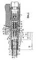
- FIG. 1shows a sectional view of a set of connectors connected together according to the invention
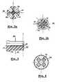
- FIG. 2 ashows a cross-sectional view of a first end of an insulator of the connector according to the invention
- FIG. 2 bshows a cross-sectional view of a second end of an insulator of the connector according to the invention
- FIG. 3shows a longitudinal sectional view of an insulator of the connector according to the invention.
- FIG. 4shows a cross-sectional view of a front part of the insulator according to the invention.
- FIG. 1shows a connector 1 according to the invention.
- the connector 1is mounted on a “quad” cable 2 . Further, the connector 1 is connected to a complementary connector 3 , wherein such complementary connector 3 can have a structure which is similar to that of connector 1 . In this case, the connector 3 is also realized according to the invention.
- the cable 2is intended to be able to convey currents at a frequency of the order of 1 GHz.
- the cable 2has preferably a characteristic impedance of the order of 100 Ohms plus or minus 20%.
- the cable 2includes four wires 4 .
- the wires 4are preferably twisted together.
- the cable 2includes for example two pairs of wires 4 . It is preferably of the Full Duplex Ethernet type, including two pairs of wires, or again four individual wires.
- These wires 4are mounted in a plait 5 functioning to insure an electromagnetic screening for the wires 4 .
- the plait 5is for example metallic.
- the cable 2comprises a sheath, preferably an insulating sheath, which surrounds the plait 5 .
- the connector 1includes a body 7 , this body 7 having preferably an extended and tubular shape, opened at a first end 8 in order for receiving the cable 2 , and opened at a second end 9 for receiving the complementary connector 3 .
- Such body 7is preferably metallic; it insures the continuity between the screen 7 and the plait 5 .
- the connector 1has means to resume the screening in the region of the first end 8 .
- the connector 1further includes an insulator 10 arranged inside the body 7 between ends 8 and 9 .
- Such insulator 10surrounds mainly the wires 4 of the cable 2 , and keeps contacts 11 of the connector 1 otherwise.
- Each of such contacts 11includes a socket 12 , each socket being connected with a core 13 of a wire 4 .
- contacts 11can include a male or female end. In the example presented in FIG. 1, the connector 1 includes contacts 11 with a female end.
- the insulator 10includes preferably three parts.
- a first partforms rear insulator 14 .
- This rear insulator 14has a cylindrical shape able to receive the still twisted wires 4 in a central cavity 15 .
- the plait 5is arranged at an outside periphery 16 of this lower insulator 14 having the shape of socket.
- An inside diameter 17 of the cavity 15 of the socket 14is of the order of an outside diameter 18 of the twisted wires 4 . Namely, some wires 4 are twisted so that they form a cylindrical wire crossing such cavity 15 .
- a portion of the sheath 6is first exposed in order that a portion of the plait 5 and the twisted wires 4 of this sheath 6 can extend beyond the rear insulator 14 .
- This intermediate piece 21is mounted around the wires 4 from the exposed end of the wires 4 .
- the intermediate piece 21is supported directly against the opening 19 of the socket 14 .
- the insulator 10further includes a front part 24 intended to receive contacts 11 .
- a front part 24intended to receive contacts 11 .
- itcomprises the channels 25 in which the contacts 11 are extended and presented.
- the front insulator 24is provided so that the channel 25 protects the female end of the contact 11 along the whole length thereof.
- the front insulator 24is provided so that the channels 25 only surround a front portion of the contact, this front portion being not intended to be connected with a complementary contact.
- the contacts 11comprise generally a flange 26 in order to be blocked in translation along an longitudinal axis 27 of the contact.
- Such flange 26cooperates with a step 28 of the front insulator 24 in order to prevent the translation thereof in a direction along an axis 29 of the connector, extending parallel to the axis 27 , of the contact 11 in the front insulator 24 .
- the translation of the insulator 24 inside the body 7 along the same axis 29is also prevented by the cooperation between a flange 30 of the outside periphery of the front insulator 24 and an inner step 31 of the body 7 .
- the front insulator 24includes a rear socket 32 adjacent to an inner surface 33 extending from the flange 30 inside body 7 .
- the insulator 10also includes an intermediate insulator 34 .
- the intermediate insulator 34is arranged between on the one hand the rear insulator 20 , possibly the intermediate piece 21 , and on the other hand the front insulator 24 .
- FIGS. 2 a and 2 bpresent a cross-sectional view of this intermediate insulator 34 .
- the connection between the wires 4 of the cable 2 and the socket 12 of the contact 11is established in the region of this intermediate insulator 34 .
- the intermediate insulator 34include channels 35 intended for receiving each at least one wire 4 , and at least one socket 12 of contact 1 that are to be connected with each other.
- the intermediate insulator 34has a cylindrical shape a cross-section of which has the shape of a circle. This circle has a center 36 .
- the arrangement of the channels 35 in this intermediate insulator 34is such that, in the region of an end 37 , the cross-section of which corresponds to FIG. 2 a , the channels 35 are held at equal distances across the center 36 .
- the intermediate insulator 34includes four intermediate channels, such as 35 .
- the four channels 35are arranged so that the respective center of each of the channels is arranged at one corner of a square 38 such that the center of this square 38 forms the center 36 .
- a distance between two juxtaposed corners of the squareis for example more or less the order of 2 cm plus or minus 0,04 cm. Moreover, a distance between a corner of this square 38 and the center 36 is of the order of 1,40 cm. The channels 35 are therefore relatively very close to the center 36 .
- each channel 35includes a step 42 allowing the retention of the sockets 12 in this portion of the intermediate insulator 34 .
- this intermediate insulator 34in order to facilitate the insertion of the socket 12 in the channels 35 , on the one hand, and on the other hand a sliding of the wires 4 so that the cores 13 fit in the sockets 12 , the channels 35 are cut as from an outside periphery 43 of the intermediate insulator 34 . It can thus be seen that the cross-section of this intermediate insulator 34 as a shape of a “clover”.
- the body 7includes a flange 47 for cooperating with resilient locks 48 , these locks 48 being presented inside an body 49 intended to receive the connector 1 .
- the flange 47abuts against an edge 50 provided in this body 49 in order to block the connector 1 in the body 49 .
- FIG. 4shows a cross-section of the front insulator 24 , wherein each of the channels 25 provided for having male or female contact ends on the contacts 11 includes a groove 51 , such groove 51 being able to cooperate with a key or an resilient blade of a contact in order to insure an unique orientation of contact inside the channel 25 . Therefore, the method of connection of the connector 1 with a complementary connector is unique, whereas the key of each of the contacts of the complementary connector must absolutely be able to be inserted correctly in the associated grooves 51 .
- the groove 51is associated locally with an increase of the size of the opening. Thus, when the front insulator 24 has to be used for receiving contacts 11 having no such pin, the presence of the groove 51 doesn't prevent the insertion of these contacts having no pin.
- the cable 2 to be inserted in the body 7 of the connector 1is first exposed.
- a differential exposing of the cableis preferably effected.
- the sheath 5is exposed along a first length 52 .
- the wires 4are then exposed along a second length 53 .
- the wires 4are exposed such as to expose the cores 13 along a third length 54 .
- the length 54is shorter than the length 53 , which in turn is shorter than the length 52 .
- the rear insulator 14is, starting from the exposed end of the cable, mounted by sliding.
- the rear insulator 14is arranged so that the sheath 6 is not inserted, and does not surround the rear insulator 14 .
- the plait 5 exposed along a length between the length 52 and the length 53is arranged at an outside periphery of the rear insulator 14 .
- the intermediate piece 21can be mounted in the same way, starting from the exposed end of the cable until it abuts against the rear insulator 14 .
- the contacts 11are inserted starting from the end 39 of the central insulator 34 .
- the sockets 12are inserted in the channels 35 from the outside periphery of this central insulator 34 .
- the wires 4are then moved away from each other in order to arrange each wires in a respective channel 35 , such that the core 13 of each wire 4 is inserted in a socket 12 .
- the front insulator 24is then mounted on the central insulator 34 , so that the male and female ends of the contacts 11 are slided into the channels 25 . There is a possible cooperation between the keys of the contacts and the grooves 51 to guarantee a correct positioning of the front insulator 24 .
- the front insulator 24is driven so that the socket 32 surrounds the central insulator 34 , and until the two insulators abut against each other.
- the assembly formed of the wires 2 and the insulator 10 thus mountedis then inserted in the body 7 until the flange 30 of the front insulator 24 abuts against the inner step 31 .
- the connector 1is then able to be arranged in the insulating body 49 and held by a set of resilient locks.
Landscapes
- Details Of Connecting Devices For Male And Female Coupling (AREA)
- Insulated Conductors (AREA)
Abstract
Description
Claims (8)
Applications Claiming Priority (3)
| Application Number | Priority Date | Filing Date | Title |
|---|---|---|---|
| FR0012319AFR2814598B1 (en) | 2000-09-27 | 2000-09-27 | CONNECTOR WITH CONTACTS MOUNTED IN A SUITABLE INSULATION |
| FR00/12319 | 2000-09-27 | ||
| FRFR00/12319 | 2000-09-27 |
Publications (2)
| Publication Number | Publication Date |
|---|---|
| US20020068483A1 US20020068483A1 (en) | 2002-06-06 |
| US6616482B2true US6616482B2 (en) | 2003-09-09 |
Family
ID=8854751
Family Applications (1)
| Application Number | Title | Priority Date | Filing Date |
|---|---|---|---|
| US09/964,993Expired - LifetimeUS6616482B2 (en) | 2000-09-27 | 2001-09-26 | Connector provided with contacts mounted in an adapted insulator |
Country Status (4)
| Country | Link |
|---|---|
| US (1) | US6616482B2 (en) |
| EP (2) | EP1641089B1 (en) |
| DE (2) | DE60126369T2 (en) |
| FR (1) | FR2814598B1 (en) |
Cited By (27)
| Publication number | Priority date | Publication date | Assignee | Title |
|---|---|---|---|---|
| US20040157493A1 (en)* | 2002-11-21 | 2004-08-12 | Bert Bergner | Connector arrangement |
| US20050112953A1 (en)* | 2003-11-25 | 2005-05-26 | Ratchford Lloyd G. | Slotted contact retention and alignment device for contact assembles |
| US20060035514A1 (en)* | 2004-08-13 | 2006-02-16 | Tyco Electronics Corporation | Electrical connector |
| US7044789B2 (en) | 2004-08-13 | 2006-05-16 | Tyco Electronics Corporation | Electrical connector |
| US20060246775A1 (en)* | 2005-03-29 | 2006-11-02 | Cruz Jose D L | Transformer for quadraxial coaxial structures |
| US7172467B1 (en) | 2005-11-22 | 2007-02-06 | Tyco Electronics Corporation | Electrical contact assembly |
| US20100081302A1 (en)* | 2008-09-29 | 2010-04-01 | Amphenol Corporation | Ground sleeve having improved impedance control and high frequency performance |
| US7753710B2 (en) | 2008-10-03 | 2010-07-13 | Amphenol Corporation | Latching system with single-handed operation for connector assembly |
| US20100294530A1 (en)* | 2008-09-29 | 2010-11-25 | Prescott Atkinson | Ground sleeve having improved impedance control and high frequency performance |
| US20110108306A1 (en)* | 2009-11-09 | 2011-05-12 | L-Com, Inc. | Right angle twisted pair connector |
| DE102010039314A1 (en) | 2010-08-13 | 2012-02-16 | Tyco Electronics Amp Gmbh | Electrical connector |
| US8221164B1 (en)* | 2009-10-30 | 2012-07-17 | The Boeing Company | Modular cable clamp with high impedance surface |
| US8491313B2 (en) | 2011-02-02 | 2013-07-23 | Amphenol Corporation | Mezzanine connector |
| US8864521B2 (en) | 2005-06-30 | 2014-10-21 | Amphenol Corporation | High frequency electrical connector |
| US20190058268A1 (en)* | 2017-08-16 | 2019-02-21 | Rosenberger Hochfrequenztechnik Gmbh & Co. Kg | Connector arrangement |
| US11444397B2 (en) | 2015-07-07 | 2022-09-13 | Amphenol Fci Asia Pte. Ltd. | Electrical connector with cavity between terminals |
| US11469554B2 (en) | 2020-01-27 | 2022-10-11 | Fci Usa Llc | High speed, high density direct mate orthogonal connector |
| US11522310B2 (en) | 2012-08-22 | 2022-12-06 | Amphenol Corporation | High-frequency electrical connector |
| US11539171B2 (en) | 2016-08-23 | 2022-12-27 | Amphenol Corporation | Connector configurable for high performance |
| US11715914B2 (en) | 2014-01-22 | 2023-08-01 | Amphenol Corporation | High speed, high density electrical connector with shielded signal paths |
| US11757215B2 (en) | 2018-09-26 | 2023-09-12 | Amphenol East Asia Electronic Technology (Shenzhen) Co., Ltd. | High speed electrical connector and printed circuit board thereof |
| US11757224B2 (en) | 2010-05-07 | 2023-09-12 | Amphenol Corporation | High performance cable connector |
| US11799246B2 (en) | 2020-01-27 | 2023-10-24 | Fci Usa Llc | High speed connector |
| US11817655B2 (en) | 2020-09-25 | 2023-11-14 | Amphenol Commercial Products (Chengdu) Co., Ltd. | Compact, high speed electrical connector |
| US11942716B2 (en) | 2020-09-22 | 2024-03-26 | Amphenol Commercial Products (Chengdu) Co., Ltd. | High speed electrical connector |
| US12300920B2 (en) | 2021-08-13 | 2025-05-13 | Amphenol Commercial Products (Chengdu) Co., Ltd. | High performance card edge connector for high bandwidth transmission |
| US12300936B2 (en) | 2019-02-19 | 2025-05-13 | Amphenol Corporation | High speed connector |
Families Citing this family (5)
| Publication number | Priority date | Publication date | Assignee | Title |
|---|---|---|---|---|
| WO2006063686A1 (en)* | 2004-12-13 | 2006-06-22 | Rosenberger Hochfrequenztechnik Gmbh & Co. Kg | Insulating part for hf plug-in connectors, especially fakra connectors |
| US7160149B1 (en)* | 2005-06-24 | 2007-01-09 | John Mezzalingua Associates, Inc. | Coaxial connector and method of connecting a two-wire cable to a coaxial connector |
| FR2934092B1 (en)* | 2008-07-15 | 2014-05-09 | Souriau | CONNECTION ASSEMBLY AND METHOD FOR MOUNTING SUCH CONNECTION ASSEMBLY |
| EP2779318A1 (en) | 2013-03-11 | 2014-09-17 | Yazaki Europe Ltd | Method for assembling an electrical connector and electrical connector |
| RU2624403C1 (en)* | 2016-08-11 | 2017-07-03 | Российская Федерация, от имени которой выступает Государственная корпорация по атомной энергии "Росатом" (Госкорпорация "Росатом") | Module slab laser with diode pumping and a zigzag course of rays (versions) |
Citations (7)
| Publication number | Priority date | Publication date | Assignee | Title |
|---|---|---|---|---|
| US3986765A (en) | 1975-02-07 | 1976-10-19 | Amp Incorporated | Power cord connector |
| US4493525A (en) | 1983-01-31 | 1985-01-15 | Amp Incorporated | Electrical plug connector and receptacle therefor |
| EP0755100A2 (en) | 1996-02-29 | 1997-01-22 | Telesafe AS | Contact set for twisted pair cable with individually shielded pairs |
| FR2762453A1 (en) | 1997-04-17 | 1998-10-23 | Soc D Fabrication Ind Et Mecan | ELECTRICAL CONNECTOR FOR HIGH FREQUENCIES |
| US5961351A (en)* | 1996-08-21 | 1999-10-05 | Hon Hai Precision Ind. Co., Ltd. | Universal serial Bus B-type plug connector |
| US6280232B1 (en)* | 1998-03-31 | 2001-08-28 | Avaya Technology Corp. | Communication cable termination |
| US6290532B1 (en)* | 2000-07-05 | 2001-09-18 | Tyco Electronics Corporation | Apparatus and method for positioning wires in a highspeed serial data connector |
Family Cites Families (4)
| Publication number | Priority date | Publication date | Assignee | Title |
|---|---|---|---|---|
| US4488768A (en)* | 1983-02-28 | 1984-12-18 | Amp Incorporated | Programmable electrical connector |
| DE4301503C2 (en)* | 1992-03-31 | 1995-08-24 | Escha Bauelemente Gmbh | Electrical connector part with union nut |
| DE19721506C2 (en)* | 1997-05-22 | 2002-02-21 | Amphenol Tuchel Elect | Electrical connector part |
| US6099345A (en)* | 1999-04-23 | 2000-08-08 | Hubbell Incorporated | Wire spacers for connecting cables to connectors |
- 2000
- 2000-09-27FRFR0012319Apatent/FR2814598B1/ennot_activeExpired - Lifetime
- 2001
- 2001-09-25DEDE60126369Tpatent/DE60126369T2/ennot_activeExpired - Lifetime
- 2001-09-25EPEP05301056Apatent/EP1641089B1/ennot_activeExpired - Lifetime
- 2001-09-25EPEP01000496Apatent/EP1193812B1/ennot_activeExpired - Lifetime
- 2001-09-25DEDE60118045Tpatent/DE60118045T2/ennot_activeExpired - Lifetime
- 2001-09-26USUS09/964,993patent/US6616482B2/ennot_activeExpired - Lifetime
Patent Citations (7)
| Publication number | Priority date | Publication date | Assignee | Title |
|---|---|---|---|---|
| US3986765A (en) | 1975-02-07 | 1976-10-19 | Amp Incorporated | Power cord connector |
| US4493525A (en) | 1983-01-31 | 1985-01-15 | Amp Incorporated | Electrical plug connector and receptacle therefor |
| EP0755100A2 (en) | 1996-02-29 | 1997-01-22 | Telesafe AS | Contact set for twisted pair cable with individually shielded pairs |
| US5961351A (en)* | 1996-08-21 | 1999-10-05 | Hon Hai Precision Ind. Co., Ltd. | Universal serial Bus B-type plug connector |
| FR2762453A1 (en) | 1997-04-17 | 1998-10-23 | Soc D Fabrication Ind Et Mecan | ELECTRICAL CONNECTOR FOR HIGH FREQUENCIES |
| US6280232B1 (en)* | 1998-03-31 | 2001-08-28 | Avaya Technology Corp. | Communication cable termination |
| US6290532B1 (en)* | 2000-07-05 | 2001-09-18 | Tyco Electronics Corporation | Apparatus and method for positioning wires in a highspeed serial data connector |
Cited By (46)
| Publication number | Priority date | Publication date | Assignee | Title |
|---|---|---|---|---|
| US20040157493A1 (en)* | 2002-11-21 | 2004-08-12 | Bert Bergner | Connector arrangement |
| US20050112953A1 (en)* | 2003-11-25 | 2005-05-26 | Ratchford Lloyd G. | Slotted contact retention and alignment device for contact assembles |
| US7494377B2 (en) | 2004-08-13 | 2009-02-24 | Tyco Electronics Corporation | Electrical connector |
| US20060035514A1 (en)* | 2004-08-13 | 2006-02-16 | Tyco Electronics Corporation | Electrical connector |
| US7044789B2 (en) | 2004-08-13 | 2006-05-16 | Tyco Electronics Corporation | Electrical connector |
| US20060246775A1 (en)* | 2005-03-29 | 2006-11-02 | Cruz Jose D L | Transformer for quadraxial coaxial structures |
| US7244147B2 (en)* | 2005-03-29 | 2007-07-17 | Souriau | Transformer for quadraxial coaxial structures |
| US9705255B2 (en) | 2005-06-30 | 2017-07-11 | Amphenol Corporation | High frequency electrical connector |
| US9219335B2 (en) | 2005-06-30 | 2015-12-22 | Amphenol Corporation | High frequency electrical connector |
| US8864521B2 (en) | 2005-06-30 | 2014-10-21 | Amphenol Corporation | High frequency electrical connector |
| EP1788667A1 (en)* | 2005-11-22 | 2007-05-23 | Tyco Electronics Corporation | Electrical contact assembly |
| US7172467B1 (en) | 2005-11-22 | 2007-02-06 | Tyco Electronics Corporation | Electrical contact assembly |
| US20100081302A1 (en)* | 2008-09-29 | 2010-04-01 | Amphenol Corporation | Ground sleeve having improved impedance control and high frequency performance |
| US20100294530A1 (en)* | 2008-09-29 | 2010-11-25 | Prescott Atkinson | Ground sleeve having improved impedance control and high frequency performance |
| US7906730B2 (en) | 2008-09-29 | 2011-03-15 | Amphenol Corporation | Ground sleeve having improved impedance control and high frequency performance |
| US9124009B2 (en) | 2008-09-29 | 2015-09-01 | Amphenol Corporation | Ground sleeve having improved impedance control and high frequency performance |
| US7753710B2 (en) | 2008-10-03 | 2010-07-13 | Amphenol Corporation | Latching system with single-handed operation for connector assembly |
| US8221164B1 (en)* | 2009-10-30 | 2012-07-17 | The Boeing Company | Modular cable clamp with high impedance surface |
| US8993887B2 (en)* | 2009-11-09 | 2015-03-31 | L-Com, Inc. | Right angle twisted pair connector |
| US20110108306A1 (en)* | 2009-11-09 | 2011-05-12 | L-Com, Inc. | Right angle twisted pair connector |
| US11757224B2 (en) | 2010-05-07 | 2023-09-12 | Amphenol Corporation | High performance cable connector |
| WO2012020000A1 (en) | 2010-08-13 | 2012-02-16 | Tyco Electronics Amp Gmbh | Electrical plug connector |
| DE102010039314A1 (en) | 2010-08-13 | 2012-02-16 | Tyco Electronics Amp Gmbh | Electrical connector |
| DE102010039314B4 (en) | 2010-08-13 | 2019-10-10 | Te Connectivity Germany Gmbh | Electrical connector |
| US8657627B2 (en) | 2011-02-02 | 2014-02-25 | Amphenol Corporation | Mezzanine connector |
| US8801464B2 (en) | 2011-02-02 | 2014-08-12 | Amphenol Corporation | Mezzanine connector |
| US8636543B2 (en) | 2011-02-02 | 2014-01-28 | Amphenol Corporation | Mezzanine connector |
| US8491313B2 (en) | 2011-02-02 | 2013-07-23 | Amphenol Corporation | Mezzanine connector |
| US11901663B2 (en) | 2012-08-22 | 2024-02-13 | Amphenol Corporation | High-frequency electrical connector |
| US11522310B2 (en) | 2012-08-22 | 2022-12-06 | Amphenol Corporation | High-frequency electrical connector |
| US11715914B2 (en) | 2014-01-22 | 2023-08-01 | Amphenol Corporation | High speed, high density electrical connector with shielded signal paths |
| US11444397B2 (en) | 2015-07-07 | 2022-09-13 | Amphenol Fci Asia Pte. Ltd. | Electrical connector with cavity between terminals |
| US11955742B2 (en) | 2015-07-07 | 2024-04-09 | Amphenol Fci Asia Pte. Ltd. | Electrical connector with cavity between terminals |
| US12341301B2 (en) | 2016-08-23 | 2025-06-24 | Amphenol Corporation | Connector configurable for high performance |
| US11539171B2 (en) | 2016-08-23 | 2022-12-27 | Amphenol Corporation | Connector configurable for high performance |
| US10965066B2 (en)* | 2017-08-16 | 2021-03-30 | Rosenberger Hochfrequenztechnik Gmbh | Connector arrangement |
| US20190058268A1 (en)* | 2017-08-16 | 2019-02-21 | Rosenberger Hochfrequenztechnik Gmbh & Co. Kg | Connector arrangement |
| US11757215B2 (en) | 2018-09-26 | 2023-09-12 | Amphenol East Asia Electronic Technology (Shenzhen) Co., Ltd. | High speed electrical connector and printed circuit board thereof |
| US12300936B2 (en) | 2019-02-19 | 2025-05-13 | Amphenol Corporation | High speed connector |
| US11469553B2 (en) | 2020-01-27 | 2022-10-11 | Fci Usa Llc | High speed connector |
| US11817657B2 (en) | 2020-01-27 | 2023-11-14 | Fci Usa Llc | High speed, high density direct mate orthogonal connector |
| US11799246B2 (en) | 2020-01-27 | 2023-10-24 | Fci Usa Llc | High speed connector |
| US11469554B2 (en) | 2020-01-27 | 2022-10-11 | Fci Usa Llc | High speed, high density direct mate orthogonal connector |
| US11942716B2 (en) | 2020-09-22 | 2024-03-26 | Amphenol Commercial Products (Chengdu) Co., Ltd. | High speed electrical connector |
| US11817655B2 (en) | 2020-09-25 | 2023-11-14 | Amphenol Commercial Products (Chengdu) Co., Ltd. | Compact, high speed electrical connector |
| US12300920B2 (en) | 2021-08-13 | 2025-05-13 | Amphenol Commercial Products (Chengdu) Co., Ltd. | High performance card edge connector for high bandwidth transmission |
Also Published As
| Publication number | Publication date |
|---|---|
| DE60126369T2 (en) | 2007-11-15 |
| DE60118045T2 (en) | 2007-03-08 |
| US20020068483A1 (en) | 2002-06-06 |
| EP1193812A1 (en) | 2002-04-03 |
| FR2814598B1 (en) | 2002-11-29 |
| EP1193812B1 (en) | 2006-03-22 |
| DE60118045D1 (en) | 2006-05-11 |
| EP1641089A3 (en) | 2006-05-31 |
| DE60126369D1 (en) | 2007-03-15 |
| EP1641089A2 (en) | 2006-03-29 |
| FR2814598A1 (en) | 2002-03-29 |
| EP1641089B1 (en) | 2007-01-24 |
Similar Documents
| Publication | Publication Date | Title |
|---|---|---|
| US6616482B2 (en) | Connector provided with contacts mounted in an adapted insulator | |
| CA1298367C (en) | Controlled impedance connector assembly | |
| US9722359B2 (en) | Electrical connector with terminal array | |
| US6007368A (en) | Telecommunications connector with improved crosstalk reduction | |
| US7044789B2 (en) | Electrical connector | |
| US6948977B1 (en) | Connector assembly and assembly method | |
| US7090501B1 (en) | Connector apparatus | |
| US20050277340A1 (en) | Modular plug assemblies, terminated cable assemblies and methods for forming the same | |
| US20090104819A1 (en) | High bandwidth connector | |
| CN113841302A (en) | Contact carrier for shielding a hybrid contact assembly and plug connector | |
| US4340265A (en) | Multi-coaxial/power pin connector assembly having integral ground | |
| US7909645B2 (en) | Coaxial cable connector housing | |
| US20030060084A1 (en) | Connector | |
| US5580261A (en) | Coaxial electrical connector also performing a switching function | |
| US20040157493A1 (en) | Connector arrangement | |
| US7118381B2 (en) | Electrical connector with contact shielding module | |
| US7371111B2 (en) | Coaxial cable connector with improved shielding | |
| EP0993075A2 (en) | Electrical connector with metallic jacket | |
| US20020151217A1 (en) | Electrically shielded connector with over-molded insulating cover | |
| US11404832B2 (en) | Connector assembly for electrically connecting two cables | |
| US5090915A (en) | Self-terminating coaxial tap connector with external termination element | |
| US4674822A (en) | Multi-conductor shielded cable | |
| JPH02216784A (en) | Microwave connectot | |
| US8961223B2 (en) | F-connector with chamfered lock ring | |
| US20090318020A1 (en) | Adapter for a coaxial cable connector |
Legal Events
| Date | Code | Title | Description |
|---|---|---|---|
| AS | Assignment | Owner name:FRAMATOME CONNECTORS INTERNATIONAL, FRANCE Free format text:ASSIGNMENT OF ASSIGNORS INTEREST;ASSIGNOR:FRAMATOME CONNECTORS INTERNATIONAL FRANCE;REEL/FRAME:012335/0814 Effective date:20010206 | |
| AS | Assignment | Owner name:FRAMATOME CONNECTORS INTERNATIONAL, FRANCE Free format text:ASSIGNMENT OF ASSIGNORS INTEREST;ASSIGNORS:DE LA CRUZ, JOSE;GUYON, JEAN-CLAUDE;PHILIPPE, ALAIN;AND OTHERS;REEL/FRAME:012438/0891;SIGNING DATES FROM 20011026 TO 20011112 | |
| AS | Assignment | Owner name:FCI, FRANCE Free format text:CHANGE OF NAME;ASSIGNOR:FRAMATOME CONNECTORS INTERNATIONAL;REEL/FRAME:013699/0551 Effective date:20010627 | |
| STCF | Information on status: patent grant | Free format text:PATENTED CASE | |
| AS | Assignment | Owner name:SOURIAU, FRANCE Free format text:ASSIGNMENT OF ASSIGNORS INTEREST;ASSIGNOR:FCI;REEL/FRAME:017537/0622 Effective date:20030410 | |
| AS | Assignment | Owner name:RADIALL, FRANCE Free format text:LICENSE AGREEMENT AND TRANSLATION;ASSIGNOR:SOURIAU;REEL/FRAME:017619/0123 Effective date:20050722 | |
| FPAY | Fee payment | Year of fee payment:4 | |
| FEPP | Fee payment procedure | Free format text:PAYOR NUMBER ASSIGNED (ORIGINAL EVENT CODE: ASPN); ENTITY STATUS OF PATENT OWNER: LARGE ENTITY | |
| FPAY | Fee payment | Year of fee payment:8 | |
| FPAY | Fee payment | Year of fee payment:12 |