US6616299B2 - Single optical element LED signal - Google Patents
Single optical element LED signalDownload PDFInfo
- Publication number
- US6616299B2 US6616299B2US10/059,827US5982702AUS6616299B2US 6616299 B2US6616299 B2US 6616299B2US 5982702 AUS5982702 AUS 5982702AUS 6616299 B2US6616299 B2US 6616299B2
- Authority
- US
- United States
- Prior art keywords
- optical element
- curved
- shaped face
- elements
- led
- Prior art date
- Legal status (The legal status is an assumption and is not a legal conclusion. Google has not performed a legal analysis and makes no representation as to the accuracy of the status listed.)
- Expired - Lifetime
Links
Images


Classifications
- F—MECHANICAL ENGINEERING; LIGHTING; HEATING; WEAPONS; BLASTING
- F21—LIGHTING
- F21V—FUNCTIONAL FEATURES OR DETAILS OF LIGHTING DEVICES OR SYSTEMS THEREOF; STRUCTURAL COMBINATIONS OF LIGHTING DEVICES WITH OTHER ARTICLES, NOT OTHERWISE PROVIDED FOR
- F21V5/00—Refractors for light sources
- F21V5/04—Refractors for light sources of lens shape
- F21V5/045—Refractors for light sources of lens shape the lens having discontinuous faces, e.g. Fresnel lenses
- F—MECHANICAL ENGINEERING; LIGHTING; HEATING; WEAPONS; BLASTING
- F21—LIGHTING
- F21V—FUNCTIONAL FEATURES OR DETAILS OF LIGHTING DEVICES OR SYSTEMS THEREOF; STRUCTURAL COMBINATIONS OF LIGHTING DEVICES WITH OTHER ARTICLES, NOT OTHERWISE PROVIDED FOR
- F21V7/00—Reflectors for light sources
- F21V7/0091—Reflectors for light sources using total internal reflection
- F—MECHANICAL ENGINEERING; LIGHTING; HEATING; WEAPONS; BLASTING
- F21—LIGHTING
- F21W—INDEXING SCHEME ASSOCIATED WITH SUBCLASSES F21K, F21L, F21S and F21V, RELATING TO USES OR APPLICATIONS OF LIGHTING DEVICES OR SYSTEMS
- F21W2111/00—Use or application of lighting devices or systems for signalling, marking or indicating, not provided for in codes F21W2102/00 – F21W2107/00
- F21W2111/02—Use or application of lighting devices or systems for signalling, marking or indicating, not provided for in codes F21W2102/00 – F21W2107/00 for roads, paths or the like
- F—MECHANICAL ENGINEERING; LIGHTING; HEATING; WEAPONS; BLASTING
- F21—LIGHTING
- F21Y—INDEXING SCHEME ASSOCIATED WITH SUBCLASSES F21K, F21L, F21S and F21V, RELATING TO THE FORM OR THE KIND OF THE LIGHT SOURCES OR OF THE COLOUR OF THE LIGHT EMITTED
- F21Y2115/00—Light-generating elements of semiconductor light sources
- F21Y2115/10—Light-emitting diodes [LED]
- Y—GENERAL TAGGING OF NEW TECHNOLOGICAL DEVELOPMENTS; GENERAL TAGGING OF CROSS-SECTIONAL TECHNOLOGIES SPANNING OVER SEVERAL SECTIONS OF THE IPC; TECHNICAL SUBJECTS COVERED BY FORMER USPC CROSS-REFERENCE ART COLLECTIONS [XRACs] AND DIGESTS
- Y10—TECHNICAL SUBJECTS COVERED BY FORMER USPC
- Y10S—TECHNICAL SUBJECTS COVERED BY FORMER USPC CROSS-REFERENCE ART COLLECTIONS [XRACs] AND DIGESTS
- Y10S362/00—Illumination
- Y10S362/80—Light emitting diode
Definitions
- the inventionrelates to the field of lighting, more specifically, in a preferred embodiment, the invention relates to a Light Emitting Diode (LED) signal with a single optical element.
- LEDLight Emitting Diode
- incandescent lamp signalstypically have a single light source (a point source), a parabolic reflector and a distribution cover.
- the energy and maintenance efficiency of LED signalshas resulted in their widespread adoption in place of incandescent lamps.
- Previous LED signalshave difficulty presenting a uniform display aspect. Individual points of light (from individual LEDs) or shadows from portions of the display aspect which are not completely covered by the LED light distribution pattern detract from uniformity (intensity homogeneity) of the prior LED signals.
- typical previous LED signalsuse a plurality of LEDs 20 , a collimating/positive element/lens 5 (collimating element), and a distribution/spreading cover/window/lens 40 (distribution cover).
- Light emitted in a conical pattern from each of the LEDs 20is directed towards the collimating element 5 , which is often in the form of a Fresnel lens or other form of positive lens having a single, specific, focal length. That is, generally parallel light rays impinging on a first side of the lens are focused by the lens onto a single point on the other side of the lens.
- the collimating element 5collects and refracts the light into a generally uniform, parallel direction (i.e.
- the collimate lightpasses to the distribution cover 40 which is required to create a specific light distribution, spreading the narrow collimated beam of light into a desired pattern optimized for the anticipated position(s) of the viewer(s), for example pedestrians and or vehicle operators in the case of traffic signals.
- Previous solutions to the intensity homogeneity problemsinclude purposely locating the LED's at a location out of focus with respect to a focal length of a collimating positive lens.
- designing the signal to be “out of focus”causes a light output design loss.
- the LEDsmay be located at an increased distance from the optical elements in a pattern where each of their light outputs overlap. The increased distance between the optical element and the LEDs allows the light emitted by the LEDs to fully cover the optical elements.
- Increasing the distance between the LEDs and the optical elementsrequires a deeper housing which may frustrate use of the LED signal in retrofit applications to existing incandescent housings and adds materials costs compared to a shallower housing.
- LED signalsmimic the front housing diameter and depth restrictions of the prior incandescent signals.
- Previous signalsuse a collimating element configured with outward facing features 15 . Because dirt will accumulate on the outward facing features of an exposed collimating element and degrade light output, a distribution cover with a generally smooth outer surface was required on the previous solutions to seal the collimating element from the environment even if creation of a light distribution pattern other than the narrow collimated light was not important.
- Light transmission losses, materials and assembly costsare minimized by using only a single optical element.
- One or more LEDsare clustered to create a light emission zone which illuminates a single optical element that forms the desired final light distribution pattern specific to the anticipated application of the signal.
- the aggregate light from the light emission zoneis transformed by the single optical element into a desired final display aspect.
- the single optical elementuses Fresnel elements in regions close to the center of the optical element and total internal reflection elements towards the outer periphery of the optical element. Both the Fresnel and the total internal reflection elements are formed on the inner face of the single optical element.
- the outer surface of the single optical elementis designed so that features, for example diffusion patterns, thereon on which dirt accumulation may occur are minimized or eliminated.
- FIG. 1is a cut-away side view of a typical Prior Art LED signal with multiple optical elements.
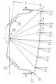
- FIG. 2is a cut-away side view of an LED signal according to one embodiment of the present invention.
- FIG. 2Ais a close-up of area 2 A of FIG. 2 .
- FIG. 2Bis a close-up of area 2 B of FIG. 2 .
- FIG. 2Cis a close-up of area 2 C of FIG. 2 .
- FIG. 3is an alternate embodiment of FIG. 2C, showing a curved total internal reflection face.
- a first embodiment in the form of an LED signalis shown in FIG. 2 .
- electronic componentscomprising, for example, a power supply and or fault indication circuitry are omitted.
- a housing 10contains one or more light sources, for example LED(s) 20 .
- the housing 10is sealed by a sealing surface of the single optical element (SOE) 50 .
- SOEsingle optical element
- an o-ring 8may be included between the housing and the single optical element 50 .
- the seal between the housing 10 and the SOE 50providing environmental isolation for the inside of the LED signal.
- the LEDsare clustered together in a concentrated light emission zone. Clustering of the LEDs into a zone simplifies the optical design of the SOE 50 .
- Clusters having an area 30% or less than the area of the SOE 50are preferred.
- the plane of the light emission zonemay be angled with respect to the backplane of the housing to assist in directing the light output in a downwards direction and to assist with sun phantom minimization in concert with a similar angle of the single optical element 50 .
- the LED(s) 20are mounted on a printed circuit board (PCB) and/or a heat sink 30 .
- the SOE 50preferably constructed of a light transmissive material, such as an acrylic, polycarbonate or other optically acceptable quality and/or cost effective material has an optical design which combines the functions of the prior collimating element 5 and the distribution cover 40 .
- the outer surface of the SOE 50is generally smooth so that opportunities for dirt buildup on the outer surface are minimized.
- a textured surfacemay be utilized as a means for diffusing the signals display aspect to obscure any imperfections/design losses/shadows in the optical solution.
- Fresnel elementscomprising Fresnel 55 and edge 57 entry faces may be used.
- Light rays incident upon the Fresnel 55 entry facesare refracted to a desired direction while the light rays incident on the edge 57 entry faces are refracted to undesired directions and treated as design losses.
- a portion of the light incident upon the Fresnel entry faces 55also reflects as shown by ray 52 .
- the Fresnel elements located farther and farther from the normal to the center of the light sourcehave corresponding angle of incidence increases as shown, for example in FIG. 2 B.
- the ratio of Fresnel 55 to edge 57 entry facesincreases along with the associated design losses and an increasing portion of light reflecting as ray 52 .
- a switch to optical features utilizing total internal reflectionis made.
- Total internal reflection optical featuresas shown in FIG. 2C, have an entry face 64 , and a total internal reflection (TIR) face 62 .
- TIRtotal internal reflection
- polycarbonate materialhas a critical angle of 38.9°.
- the incident light rayis designed to be at an angle A 3 of more than 38.9° with respect to a normal to the TIR face 62 and the outer surface of the TIR face 62 is surrounded by air, or other medium of equal or lesser density than air, total internal reflection will occur.
- Total internal reflectionremoves any requirement that the reflector surfaces be mirror coated.
- the distance X(FIG. 2) between the LED(s) 20 and the SOE 50 directly affects the angles of incidence across the SOE 50 from center to periphery.
- a shorter distance Xenables overall housing 10 depth to be minimized, allowing reductions in materials costs and retrofitting of the signal into housings originally intended for incandescent light sources.
- the location of the transition between Fresnel and TIR optical featureswill be changed with TIR optical features starting closer to center with shorter distances X.
- the entry face 64begins to create a shadow on the entry face 64 next in line towards the periphery.
- the maximum angle of incidence A 4is limited, thereby defining the minimum distance X that may be used with a specific SOE 50 diameter.
- a ratio of the Fresnel diameter to the distance X of up to 3may be achieved.
- a standard 12 inch diameter signalmay have a light emission zone at a distance X of 4 inches from the SOE 50 . Where depth is not a constraint, ratios as low as 0.5 may be used. Below this point, an all Fresnel SOE 50 may be used, eliminating the need for the TIR optical features.
- Shadowsmay be compensated for by forming the TIR face 62 in a curve, as shown in FIG. 3, to redirect a portion of the reflected light into any shadow region that may be present (at the desired viewing distance).
- each Fresnel and or TIR optical featureis calculated to re-direct the average incident light ray (the light rays each coming from different points of each LED in the light emission zone) into the desired direction, within the bounds of the type of optical feature applied.
- Curved TIR 62 and or Fresnel 55 facesmay also be used in configuring the light output through the SOE 50 into the precise desired final light distribution.
- Optical raytracing engineering softwaremay be used to assist with calculating the exact optical surface characteristics that deliver the desired light distribution for the LED signal.
- the SOE 50may be designed to be capable of manufacture by injection molding. Use of two part injection molds requires that the optical surfaces and SOE 50 to housing 10 contact and sealing surfaces be designed free of countersinking to allow mold separation.
- the SOE 50 according to the inventionis not limited to signals utilizing only conventional LED(s).
- multiple LED diesmay be combined into a single encapsulated LED package with or without an integrated heatsink.
- LED's 20 of different colorsmay be used with a single optical element 50 that is clear.
- the single optical element 50may be formed from different colored or tinted material, for example, white, red, yellow and green.
Landscapes
- Engineering & Computer Science (AREA)
- General Engineering & Computer Science (AREA)
- Non-Portable Lighting Devices Or Systems Thereof (AREA)
Abstract
Description
Claims (27)
Priority Applications (1)
| Application Number | Priority Date | Filing Date | Title |
|---|---|---|---|
| US10/059,827US6616299B2 (en) | 2001-02-02 | 2002-01-30 | Single optical element LED signal |
Applications Claiming Priority (2)
| Application Number | Priority Date | Filing Date | Title |
|---|---|---|---|
| US26636001P | 2001-02-02 | 2001-02-02 | |
| US10/059,827US6616299B2 (en) | 2001-02-02 | 2002-01-30 | Single optical element LED signal |
Publications (2)
| Publication Number | Publication Date |
|---|---|
| US20020105801A1 US20020105801A1 (en) | 2002-08-08 |
| US6616299B2true US6616299B2 (en) | 2003-09-09 |
Family
ID=26739239
Family Applications (1)
| Application Number | Title | Priority Date | Filing Date |
|---|---|---|---|
| US10/059,827Expired - LifetimeUS6616299B2 (en) | 2001-02-02 | 2002-01-30 | Single optical element LED signal |
Country Status (1)
| Country | Link |
|---|---|
| US (1) | US6616299B2 (en) |
Cited By (43)
| Publication number | Priority date | Publication date | Assignee | Title |
|---|---|---|---|---|
| US20030076237A1 (en)* | 2000-05-10 | 2003-04-24 | Simon Blumel | Signaling device for traffic signals |
| US20040037089A1 (en)* | 2002-05-16 | 2004-02-26 | Bushell Timothy George | Light source |
| US20040042208A1 (en)* | 2002-09-04 | 2004-03-04 | Wu Chen H. | Light emitting diode retrofit module for traffic signal lights |
| US20040070519A1 (en)* | 2002-09-04 | 2004-04-15 | Wu Chen H. | Compact light emitting diode retrofit lamp and method for traffic signal lights |
| US20050190553A1 (en)* | 2003-09-22 | 2005-09-01 | Manuel Lynch | Lighting apparatus |
| US20060209558A1 (en)* | 2005-03-21 | 2006-09-21 | Visteon Global Technologies, Inc. | Lens assembly for an automobile light assembly having LED light source |
| US7160010B1 (en) | 2005-11-15 | 2007-01-09 | Visteon Global Technologies, Inc. | Light manifold for automotive light module |
| US20070109791A1 (en)* | 2005-11-15 | 2007-05-17 | Visteon Global Technologies, Inc. | Side emitting near field lens |
| US20070121331A1 (en)* | 2005-11-29 | 2007-05-31 | Visteon Global Technologies, Inc. | Light assembly for automotive lighting applications |
| US20070147041A1 (en)* | 2005-10-14 | 2007-06-28 | Kabushiki Kaisha Toshiba | Lighting system |
| US20070211473A1 (en)* | 2006-03-10 | 2007-09-13 | John Patrick Peck | Light emitting diode module with improved light distribution uniformity |
| US20070274070A1 (en)* | 2006-05-25 | 2007-11-29 | Union Switch & Signal, Inc. | Light emitting diode signaling device and method of providing an indication using the same |
| US7401948B2 (en) | 2005-10-17 | 2008-07-22 | Visteon Global Technologies, Inc. | Near field lens having reduced size |
| US20080239722A1 (en)* | 2007-04-02 | 2008-10-02 | Ruud Lighting, Inc. | Light-Directing LED Apparatus |
| US20080259630A1 (en)* | 2007-04-17 | 2008-10-23 | Jeyachandrabose Chinniah | Lens assembly |
| US7564070B2 (en) | 2005-11-23 | 2009-07-21 | Visteon Global Technologies, Inc. | Light emitting diode device having a shield and/or filter |
| US20100271708A1 (en)* | 2009-04-28 | 2010-10-28 | Ruud Lighting, Inc. | Lens with controlled light refraction |
| US7841750B2 (en) | 2008-08-01 | 2010-11-30 | Ruud Lighting, Inc. | Light-directing lensing member with improved angled light distribution |
| US20100302786A1 (en)* | 2008-05-23 | 2010-12-02 | Ruud Lighting, Inc. | Lens with controlled backlight management |
| US20110134636A1 (en)* | 2009-12-07 | 2011-06-09 | Kuo-Hui Chang | Led traffic signal device |
| US8388193B2 (en) | 2008-05-23 | 2013-03-05 | Ruud Lighting, Inc. | Lens with TIR for off-axial light distribution |
| USD697664S1 (en) | 2012-05-07 | 2014-01-14 | Cree, Inc. | LED lens |
| US20140198507A1 (en)* | 2010-01-11 | 2014-07-17 | Gary R. Allen | Compact light-mixing led light engine and white led lamp with narrow beam and high cri using same |
| USD718490S1 (en) | 2013-03-15 | 2014-11-25 | Cree, Inc. | LED lens |
| US9120423B2 (en)* | 2010-03-30 | 2015-09-01 | Hella Kgaa Hueck & Co. | Lighting device for vehicles |
| US20160025306A1 (en)* | 2014-07-23 | 2016-01-28 | Powerarc, Inc. | Changeable emergency warning light assembly |
| US9255686B2 (en) | 2009-05-29 | 2016-02-09 | Cree, Inc. | Multi-lens LED-array optic system |
| US20160054502A1 (en)* | 2014-08-22 | 2016-02-25 | Bright Led Electronics Corp. | Light-emitting module |
| US9416926B2 (en) | 2009-04-28 | 2016-08-16 | Cree, Inc. | Lens with inner-cavity surface shaped for controlled light refraction |
| US9423096B2 (en) | 2008-05-23 | 2016-08-23 | Cree, Inc. | LED lighting apparatus |
| US9523479B2 (en) | 2014-01-03 | 2016-12-20 | Cree, Inc. | LED lens |
| US9541257B2 (en) | 2012-02-29 | 2017-01-10 | Cree, Inc. | Lens for primarily-elongate light distribution |
| US9541277B2 (en) | 2011-03-29 | 2017-01-10 | GE Lighting Solutions, LLC | Watertight plastic lamp seal |
| US9541258B2 (en) | 2012-02-29 | 2017-01-10 | Cree, Inc. | Lens for wide lateral-angle distribution |
| US20170211774A1 (en)* | 2014-07-23 | 2017-07-27 | Myotek Pacific Corp. | Fog lamp lens and assembly |
| US9757912B2 (en) | 2014-08-27 | 2017-09-12 | Cree, Inc. | One-piece multi-lens optical member with ultraviolet inhibitor and method of manufacture |
| US20170327033A1 (en)* | 2014-12-22 | 2017-11-16 | Hella Kgaa Hueck & Co. | Lighting device for vehicles |
| US20180231209A1 (en)* | 2015-08-24 | 2018-08-16 | Osram Gmbh | Illumination device |
| US10119662B2 (en) | 2009-04-28 | 2018-11-06 | Cree, Inc. | Lens with controlled light refraction |
| CN110168277A (en)* | 2017-01-13 | 2019-08-23 | 亮锐控股有限公司 | Array with light emitting diode and variation lens |
| US10408429B2 (en) | 2012-02-29 | 2019-09-10 | Ideal Industries Lighting Llc | Lens for preferential-side distribution |
| US10468566B2 (en) | 2017-04-10 | 2019-11-05 | Ideal Industries Lighting Llc | Hybrid lens for controlled light distribution |
| US12017793B2 (en) | 2022-10-06 | 2024-06-25 | Goodrich Lighting Systems GmbH & Co. KG | Exterior aircraft light with integrated light output monitoring, aircraft comprising such exterior aircraft light, and method for monitoring a light output of an exterior aircraft light |
Families Citing this family (28)
| Publication number | Priority date | Publication date | Assignee | Title |
|---|---|---|---|---|
| EP1344200A1 (en)* | 2000-12-22 | 2003-09-17 | Osram Opto Semiconductors GmbH | Led-signal device for traffic lights |
| DE10392669T5 (en)* | 2002-05-17 | 2005-07-07 | Ccs Inc. | A light emitting diode unit and a method of manufacturing a light emitting diode unit |
| US6827475B2 (en)* | 2002-09-09 | 2004-12-07 | Steven Robert Vetorino | LED light collection and uniform transmission system |
| DE10315131A1 (en)* | 2003-04-03 | 2004-10-14 | Hella Kg Hueck & Co. | Headlights for vehicles |
| US20050190563A1 (en)* | 2004-02-26 | 2005-09-01 | Ying Hung Li | Lighting module with dual-profiled Fresnel lens |
| US7520650B2 (en)* | 2004-06-28 | 2009-04-21 | Whelen Engineering Company, Inc. | Side-emitting collimator |
| JP2006049657A (en)* | 2004-08-06 | 2006-02-16 | Citizen Electronics Co Ltd | LED lamp |
| FR2886374B1 (en)* | 2005-05-25 | 2007-07-13 | M F I Sarl | BICOLOR LANTERN FOR EQUIPPING A WORK TRAIN |
| US7888875B2 (en)* | 2006-11-21 | 2011-02-15 | Ceit Entreprises | Lighting device such as a LED reading light |
| US20080265736A1 (en)* | 2007-04-24 | 2008-10-30 | Cheng-Tang Chen | Led reflective spherical lamp |
| US7967477B2 (en)* | 2007-09-06 | 2011-06-28 | Philips Lumileds Lighting Company Llc | Compact optical system and lenses for producing uniform collimated light |
| ITPD20070426A1 (en)* | 2007-12-21 | 2009-06-22 | Minu Lamp Srl | ILLUMINATING BODY WITH LENS |
| CN101576229A (en)* | 2008-05-07 | 2009-11-11 | 富准精密工业(深圳)有限公司 | Street light luminescence module, luminescence component and lens thereof |
| JP5407054B2 (en)* | 2008-08-01 | 2014-02-05 | 日亜化学工業株式会社 | Lighting device |
| DE102009047882A1 (en)* | 2009-09-30 | 2011-03-31 | Osram Opto Semiconductors Gmbh | LED traffic signal |
| CN102818161B (en)* | 2012-09-04 | 2015-12-02 | 上海九高节能技术有限公司 | A kind of LED lamp |
| US9383083B2 (en) | 2012-11-30 | 2016-07-05 | Koninklijke Philips N.V. | Lighting unit, especially for road illumination |
| US9851070B2 (en)* | 2013-09-09 | 2017-12-26 | Wavefront Technology, Inc. | Systems and methods to impart visual quality to illumination systems |
| JP5920612B2 (en)* | 2013-10-24 | 2016-05-18 | フィリップス ライティング ホールディング ビー ヴィ | Optical structure having two or more microstructured films |
| EP3007147A1 (en)* | 2014-10-06 | 2016-04-13 | Dialight Garufo GmbH | Traffic signal transmitter |
| TW201627961A (en)* | 2015-01-28 | 2016-08-01 | 光寶科技股份有限公司 | Signal light |
| KR20160096318A (en) | 2015-02-05 | 2016-08-16 | 현대자동차주식회사 | Battery charging status indicator for electric vehicle |
| US9719657B2 (en)* | 2015-06-09 | 2017-08-01 | Hazard Systems Pty Ltd. | Low-profile optical warning system |
| WO2017050598A1 (en)* | 2015-09-21 | 2017-03-30 | Philips Lighting Holding B.V. | Efficient collimating optics by collecting the full hemisphere in tir-fresnel lens designs |
| US9810394B2 (en)* | 2015-11-13 | 2017-11-07 | Ford Global Technologies, Llc | Vehicular signal and daytime running light assemblies with uniform illumination |
| CN107152649B (en)* | 2017-05-26 | 2024-01-30 | 华域视觉科技(上海)有限公司 | Thick-wall condenser structure for enclosing peripheral parts and mounting method thereof |
| JP6897641B2 (en)* | 2018-08-31 | 2021-07-07 | 日亜化学工業株式会社 | Lenses and light emitting devices and their manufacturing methods |
| JP7543837B2 (en)* | 2020-10-23 | 2024-09-03 | スズキ株式会社 | Lamp unit |
Citations (5)
| Publication number | Priority date | Publication date | Assignee | Title |
|---|---|---|---|---|
| US2191278A (en)* | 1937-12-13 | 1940-02-20 | Roy W Johnson | Vehicle lamp |
| US5062027A (en)* | 1989-02-09 | 1991-10-29 | Koito Manufacturing Co., Ltd. | Automobile signal lamp |
| US5323302A (en)* | 1992-05-12 | 1994-06-21 | Robert Bosch Gmbh | Illumination device |
| US5947587A (en)* | 1996-10-16 | 1999-09-07 | U.S. Philips Corporation | Signal lamp with LEDs |
| US6352359B1 (en)* | 1998-08-25 | 2002-03-05 | Physical Optics Corporation | Vehicle light assembly including a diffuser surface structure |
- 2002
- 2002-01-30USUS10/059,827patent/US6616299B2/ennot_activeExpired - Lifetime
Patent Citations (5)
| Publication number | Priority date | Publication date | Assignee | Title |
|---|---|---|---|---|
| US2191278A (en)* | 1937-12-13 | 1940-02-20 | Roy W Johnson | Vehicle lamp |
| US5062027A (en)* | 1989-02-09 | 1991-10-29 | Koito Manufacturing Co., Ltd. | Automobile signal lamp |
| US5323302A (en)* | 1992-05-12 | 1994-06-21 | Robert Bosch Gmbh | Illumination device |
| US5947587A (en)* | 1996-10-16 | 1999-09-07 | U.S. Philips Corporation | Signal lamp with LEDs |
| US6352359B1 (en)* | 1998-08-25 | 2002-03-05 | Physical Optics Corporation | Vehicle light assembly including a diffuser surface structure |
Cited By (71)
| Publication number | Priority date | Publication date | Assignee | Title |
|---|---|---|---|---|
| US6970296B2 (en)* | 2000-05-10 | 2005-11-29 | Osram Gmbh | Signaling device for traffic signals |
| US20030076237A1 (en)* | 2000-05-10 | 2003-04-24 | Simon Blumel | Signaling device for traffic signals |
| US20040037089A1 (en)* | 2002-05-16 | 2004-02-26 | Bushell Timothy George | Light source |
| US7025484B2 (en)* | 2002-05-16 | 2006-04-11 | Oxley Developments Company Limited | Light source |
| US6911915B2 (en)* | 2002-09-04 | 2005-06-28 | Leotek Electronics Corporation | Compact light emitting diode retrofit lamp and method for traffic signal lights |
| US6905227B2 (en) | 2002-09-04 | 2005-06-14 | Leotek Electronics Corporation | Light emitting diode retrofit module for traffic signal lights |
| US20040070519A1 (en)* | 2002-09-04 | 2004-04-15 | Wu Chen H. | Compact light emitting diode retrofit lamp and method for traffic signal lights |
| US20040042208A1 (en)* | 2002-09-04 | 2004-03-04 | Wu Chen H. | Light emitting diode retrofit module for traffic signal lights |
| US8079731B2 (en) | 2003-09-22 | 2011-12-20 | Permlight Products, Inc. | Lighting apparatus |
| US20050190553A1 (en)* | 2003-09-22 | 2005-09-01 | Manuel Lynch | Lighting apparatus |
| US20080055915A1 (en)* | 2003-09-22 | 2008-03-06 | Permlight Products, Inc. | Lighting apparatus |
| US7329024B2 (en) | 2003-09-22 | 2008-02-12 | Permlight Products, Inc. | Lighting apparatus |
| US20060209558A1 (en)* | 2005-03-21 | 2006-09-21 | Visteon Global Technologies, Inc. | Lens assembly for an automobile light assembly having LED light source |
| US7465075B2 (en) | 2005-03-21 | 2008-12-16 | Visteon Global Technologies, Inc. | Lens assembly for an automobile light assembly having LED light source |
| US20070147041A1 (en)* | 2005-10-14 | 2007-06-28 | Kabushiki Kaisha Toshiba | Lighting system |
| US7648256B2 (en)* | 2005-10-14 | 2010-01-19 | Kabushiki Kaisha Toshiba | Lighting system having lenses for light sources emitting rays at different wavelengths |
| US7401948B2 (en) | 2005-10-17 | 2008-07-22 | Visteon Global Technologies, Inc. | Near field lens having reduced size |
| US20070109791A1 (en)* | 2005-11-15 | 2007-05-17 | Visteon Global Technologies, Inc. | Side emitting near field lens |
| US7160010B1 (en) | 2005-11-15 | 2007-01-09 | Visteon Global Technologies, Inc. | Light manifold for automotive light module |
| US7489453B2 (en) | 2005-11-15 | 2009-02-10 | Visteon Global Technologies, Inc. | Side emitting near field lens |
| US7564070B2 (en) | 2005-11-23 | 2009-07-21 | Visteon Global Technologies, Inc. | Light emitting diode device having a shield and/or filter |
| US20070121331A1 (en)* | 2005-11-29 | 2007-05-31 | Visteon Global Technologies, Inc. | Light assembly for automotive lighting applications |
| US7438454B2 (en) | 2005-11-29 | 2008-10-21 | Visteon Global Technologies, Inc. | Light assembly for automotive lighting applications |
| US20070211473A1 (en)* | 2006-03-10 | 2007-09-13 | John Patrick Peck | Light emitting diode module with improved light distribution uniformity |
| US7810963B2 (en)* | 2006-03-10 | 2010-10-12 | Dialight Corporation | Light emitting diode module with improved light distribution uniformity |
| US7553044B2 (en) | 2006-05-25 | 2009-06-30 | Ansaldo Sts Usa, Inc. | Light emitting diode signaling device and method of providing an indication using the same |
| US20070274070A1 (en)* | 2006-05-25 | 2007-11-29 | Union Switch & Signal, Inc. | Light emitting diode signaling device and method of providing an indication using the same |
| US7618163B2 (en) | 2007-04-02 | 2009-11-17 | Ruud Lighting, Inc. | Light-directing LED apparatus |
| US20080239722A1 (en)* | 2007-04-02 | 2008-10-02 | Ruud Lighting, Inc. | Light-Directing LED Apparatus |
| US7554742B2 (en) | 2007-04-17 | 2009-06-30 | Visteon Global Technologies, Inc. | Lens assembly |
| US20080259630A1 (en)* | 2007-04-17 | 2008-10-23 | Jeyachandrabose Chinniah | Lens assembly |
| US8348475B2 (en) | 2008-05-23 | 2013-01-08 | Ruud Lighting, Inc. | Lens with controlled backlight management |
| US9657918B2 (en) | 2008-05-23 | 2017-05-23 | Cree, Inc. | Light fixture with wide-angle light distribution |
| US9476570B2 (en) | 2008-05-23 | 2016-10-25 | Cree, Inc. | Lens with controlled backlight management |
| US9423096B2 (en) | 2008-05-23 | 2016-08-23 | Cree, Inc. | LED lighting apparatus |
| US8388193B2 (en) | 2008-05-23 | 2013-03-05 | Ruud Lighting, Inc. | Lens with TIR for off-axial light distribution |
| US20100302786A1 (en)* | 2008-05-23 | 2010-12-02 | Ruud Lighting, Inc. | Lens with controlled backlight management |
| US7841750B2 (en) | 2008-08-01 | 2010-11-30 | Ruud Lighting, Inc. | Light-directing lensing member with improved angled light distribution |
| US20100271708A1 (en)* | 2009-04-28 | 2010-10-28 | Ruud Lighting, Inc. | Lens with controlled light refraction |
| US10119662B2 (en) | 2009-04-28 | 2018-11-06 | Cree, Inc. | Lens with controlled light refraction |
| US9217854B2 (en) | 2009-04-28 | 2015-12-22 | Cree, Inc. | Lens with controlled light refraction |
| US9416926B2 (en) | 2009-04-28 | 2016-08-16 | Cree, Inc. | Lens with inner-cavity surface shaped for controlled light refraction |
| US9689552B2 (en) | 2009-05-29 | 2017-06-27 | Cree, Inc. | Multi-lens LED-array optic system |
| US9255686B2 (en) | 2009-05-29 | 2016-02-09 | Cree, Inc. | Multi-lens LED-array optic system |
| US20110134636A1 (en)* | 2009-12-07 | 2011-06-09 | Kuo-Hui Chang | Led traffic signal device |
| US20140198507A1 (en)* | 2010-01-11 | 2014-07-17 | Gary R. Allen | Compact light-mixing led light engine and white led lamp with narrow beam and high cri using same |
| US9534743B2 (en)* | 2010-01-11 | 2017-01-03 | GE Lighting Solutions, LLC | Directional lamp with beam forming optical system including a lens and collecting reflector |
| US9120423B2 (en)* | 2010-03-30 | 2015-09-01 | Hella Kgaa Hueck & Co. | Lighting device for vehicles |
| US9541277B2 (en) | 2011-03-29 | 2017-01-10 | GE Lighting Solutions, LLC | Watertight plastic lamp seal |
| US10408429B2 (en) | 2012-02-29 | 2019-09-10 | Ideal Industries Lighting Llc | Lens for preferential-side distribution |
| US9541257B2 (en) | 2012-02-29 | 2017-01-10 | Cree, Inc. | Lens for primarily-elongate light distribution |
| US9541258B2 (en) | 2012-02-29 | 2017-01-10 | Cree, Inc. | Lens for wide lateral-angle distribution |
| USD697664S1 (en) | 2012-05-07 | 2014-01-14 | Cree, Inc. | LED lens |
| USD708387S1 (en) | 2012-05-07 | 2014-07-01 | Cree, Inc. | LED lens |
| USD718490S1 (en) | 2013-03-15 | 2014-11-25 | Cree, Inc. | LED lens |
| US9523479B2 (en) | 2014-01-03 | 2016-12-20 | Cree, Inc. | LED lens |
| US20160025306A1 (en)* | 2014-07-23 | 2016-01-28 | Powerarc, Inc. | Changeable emergency warning light assembly |
| US9696015B2 (en)* | 2014-07-23 | 2017-07-04 | Powerarc, Inc. | Changeable emergency warning light assembly |
| US20170211774A1 (en)* | 2014-07-23 | 2017-07-27 | Myotek Pacific Corp. | Fog lamp lens and assembly |
| US10240741B2 (en)* | 2014-07-23 | 2019-03-26 | Myotek Holdings, Inc. | Fog lamp lens and assembly |
| US20160054502A1 (en)* | 2014-08-22 | 2016-02-25 | Bright Led Electronics Corp. | Light-emitting module |
| US9757912B2 (en) | 2014-08-27 | 2017-09-12 | Cree, Inc. | One-piece multi-lens optical member with ultraviolet inhibitor and method of manufacture |
| US20170327033A1 (en)* | 2014-12-22 | 2017-11-16 | Hella Kgaa Hueck & Co. | Lighting device for vehicles |
| US11193646B2 (en)* | 2014-12-22 | 2021-12-07 | Hella Kgaa Hueck & Co. | Lighting device for vehicles |
| US20180231209A1 (en)* | 2015-08-24 | 2018-08-16 | Osram Gmbh | Illumination device |
| US10502392B2 (en)* | 2015-08-24 | 2019-12-10 | Osram Gmbh | Illumination device |
| CN110168277A (en)* | 2017-01-13 | 2019-08-23 | 亮锐控股有限公司 | Array with light emitting diode and variation lens |
| CN110168277B (en)* | 2017-01-13 | 2020-11-24 | 亮锐控股有限公司 | Arrays with light-emitting diodes and changing lenses |
| US11302732B2 (en) | 2017-01-13 | 2022-04-12 | Lumileds Llc | Array with light emitting diodes and varying lens |
| US10468566B2 (en) | 2017-04-10 | 2019-11-05 | Ideal Industries Lighting Llc | Hybrid lens for controlled light distribution |
| US12017793B2 (en) | 2022-10-06 | 2024-06-25 | Goodrich Lighting Systems GmbH & Co. KG | Exterior aircraft light with integrated light output monitoring, aircraft comprising such exterior aircraft light, and method for monitoring a light output of an exterior aircraft light |
Also Published As
| Publication number | Publication date |
|---|---|
| US20020105801A1 (en) | 2002-08-08 |
Similar Documents
| Publication | Publication Date | Title |
|---|---|---|
| US6616299B2 (en) | Single optical element LED signal | |
| US7648256B2 (en) | Lighting system having lenses for light sources emitting rays at different wavelengths | |
| US7237924B2 (en) | LED signal lamp | |
| US8529102B2 (en) | Reflector system for lighting device | |
| US20220099271A1 (en) | Line Source Lighting System | |
| US6758582B1 (en) | LED lighting device | |
| US6729746B2 (en) | Light source device | |
| KR101212911B1 (en) | Lighting module and luminaire | |
| US5592578A (en) | Peripheral optical element for redirecting light from an LED | |
| US20190186710A1 (en) | Led light fixture with light shaping features | |
| US20090129084A1 (en) | Optical device for altering light shape and light source module comprising same | |
| WO2020244229A1 (en) | Optical component for vehicle light, and vehicle headlight | |
| TWI712841B (en) | Light-emitting device, light-emitting module, and backlight module | |
| EP3754248B1 (en) | Optical element and lighting lamp with the same | |
| JP5290414B2 (en) | Holding frame with at least one optical element | |
| JP2011198473A (en) | Condensing optical element and device using the same | |
| JP5307717B2 (en) | Self-luminous light emitting device | |
| CN217763273U (en) | Optical assembly, lighting and/or signalling device, and motor vehicle | |
| CN210568144U (en) | Light path conduction assembly for car lamp and car lamp | |
| CN209977777U (en) | Strip-shaped lamp | |
| CN217714789U (en) | Novel high beam module for vehicle | |
| CN223345215U (en) | A high-transmittance LED lens and a high-brightness spotlight | |
| CN217584144U (en) | Light control device and lamp | |
| CN221801559U (en) | Laser lighting module | |
| JP7300879B2 (en) | Optical lens, light source device and illumination device |
Legal Events
| Date | Code | Title | Description |
|---|---|---|---|
| AS | Assignment | Owner name:GELCORE LLC, OHIO Free format text:ASSIGNMENT OF ASSIGNORS INTEREST;ASSIGNOR:MARTINEAU, PATRICK;REEL/FRAME:012577/0253 Effective date:20020129 | |
| STCF | Information on status: patent grant | Free format text:PATENTED CASE | |
| FPAY | Fee payment | Year of fee payment:4 | |
| FPAY | Fee payment | Year of fee payment:8 | |
| FPAY | Fee payment | Year of fee payment:12 | |
| AS | Assignment | Owner name:LUMINATION, LLC, OHIO Free format text:CHANGE OF NAME;ASSIGNOR:GELCORE, LLC;REEL/FRAME:048830/0474 Effective date:20070122 Owner name:GE LIGHTING SOLUTIONS, LLC, OHIO Free format text:CHANGE OF NAME;ASSIGNOR:LUMINATION, LLC;REEL/FRAME:048832/0057 Effective date:20100721 Owner name:CURRENT LIGHTING SOLUTIONS, LLC, OHIO Free format text:CHANGE OF NAME;ASSIGNOR:GE LIGHTING SOLUTIONS, LLC;REEL/FRAME:048840/0677 Effective date:20190401 | |
| AS | Assignment | Owner name:ALLY BANK, AS COLLATERAL AGENT, NEW YORK Free format text:SECURITY AGREEMENT;ASSIGNORS:HUBBELL LIGHTING, INC.;LITECONTROL CORPORATION;CURRENT LIGHTING SOLUTIONS, LLC;AND OTHERS;REEL/FRAME:058982/0844 Effective date:20220201 | |
| AS | Assignment | Owner name:ATLANTIC PARK STRATEGIC CAPITAL FUND, L.P., AS COLLATERAL AGENT, NEW YORK Free format text:SECURITY INTEREST;ASSIGNORS:HUBBELL LIGHTING, INC.;LITECONTROL CORPORATION;CURRENT LIGHTING SOLUTIONS, LLC;AND OTHERS;REEL/FRAME:059034/0469 Effective date:20220201 | |
| AS | Assignment | Owner name:ALLY BANK, AS COLLATERAL AGENT, NEW YORK Free format text:CORRECTIVE ASSIGNMENT TO CORRECT THE PATENT NUMBER 10841994 TO PATENT NUMBER 11570872 PREVIOUSLY RECORDED ON REEL 058982 FRAME 0844. ASSIGNOR(S) HEREBY CONFIRMS THE SECURITY AGREEMENT;ASSIGNORS:HUBBELL LIGHTING, INC.;LITECONTROL CORPORATION;CURRENT LIGHTING SOLUTIONS, LLC;AND OTHERS;REEL/FRAME:066355/0455 Effective date:20220201 | |
| AS | Assignment | Owner name:ATLANTIC PARK STRATEGIC CAPITAL FUND, L.P., AS COLLATERAL AGENT, NEW YORK Free format text:CORRECTIVE ASSIGNMENT TO CORRECT THE PATENT NUMBER PREVIOUSLY RECORDED AT REEL: 059034 FRAME: 0469. ASSIGNOR(S) HEREBY CONFIRMS THE SECURITY INTEREST;ASSIGNORS:HUBBELL LIGHTING, INC.;LITECONTROL CORPORATION;CURRENT LIGHTING SOLUTIONS, LLC;AND OTHERS;REEL/FRAME:066372/0590 Effective date:20220201 |