US6616066B2 - Injection valve - Google Patents
Injection valveDownload PDFInfo
- Publication number
- US6616066B2 US6616066B2US09/770,293US77029301AUS6616066B2US 6616066 B2US6616066 B2US 6616066B2US 77029301 AUS77029301 AUS 77029301AUS 6616066 B2US6616066 B2US 6616066B2
- Authority
- US
- United States
- Prior art keywords
- injection valve
- ducts
- valve according
- filter element
- fuel
- Prior art date
- Legal status (The legal status is an assumption and is not a legal conclusion. Google has not performed a legal analysis and makes no representation as to the accuracy of the status listed.)
- Expired - Fee Related, expires
Links
Images


Classifications
- F—MECHANICAL ENGINEERING; LIGHTING; HEATING; WEAPONS; BLASTING
- F02—COMBUSTION ENGINES; HOT-GAS OR COMBUSTION-PRODUCT ENGINE PLANTS
- F02M—SUPPLYING COMBUSTION ENGINES IN GENERAL WITH COMBUSTIBLE MIXTURES OR CONSTITUENTS THEREOF
- F02M53/00—Fuel-injection apparatus characterised by having heating, cooling or thermally-insulating means
- F02M53/04—Injectors with heating, cooling, or thermally-insulating means
- F02M53/06—Injectors with heating, cooling, or thermally-insulating means with fuel-heating means, e.g. for vaporising
- F—MECHANICAL ENGINEERING; LIGHTING; HEATING; WEAPONS; BLASTING
- F02—COMBUSTION ENGINES; HOT-GAS OR COMBUSTION-PRODUCT ENGINE PLANTS
- F02M—SUPPLYING COMBUSTION ENGINES IN GENERAL WITH COMBUSTIBLE MIXTURES OR CONSTITUENTS THEREOF
- F02M31/00—Apparatus for thermally treating combustion-air, fuel, or fuel-air mixture
- F02M31/02—Apparatus for thermally treating combustion-air, fuel, or fuel-air mixture for heating
- F02M31/12—Apparatus for thermally treating combustion-air, fuel, or fuel-air mixture for heating electrically
- F02M31/125—Fuel
- F—MECHANICAL ENGINEERING; LIGHTING; HEATING; WEAPONS; BLASTING
- F02—COMBUSTION ENGINES; HOT-GAS OR COMBUSTION-PRODUCT ENGINE PLANTS
- F02M—SUPPLYING COMBUSTION ENGINES IN GENERAL WITH COMBUSTIBLE MIXTURES OR CONSTITUENTS THEREOF
- F02M37/00—Apparatus or systems for feeding liquid fuel from storage containers to carburettors or fuel-injection apparatus; Arrangements for purifying liquid fuel specially adapted for, or arranged on, internal-combustion engines
- F02M37/22—Arrangements for purifying liquid fuel specially adapted for, or arranged on, internal-combustion engines, e.g. arrangements in the feeding system
- F02M37/30—Arrangements for purifying liquid fuel specially adapted for, or arranged on, internal-combustion engines, e.g. arrangements in the feeding system characterised by heating means
- F—MECHANICAL ENGINEERING; LIGHTING; HEATING; WEAPONS; BLASTING
- F02—COMBUSTION ENGINES; HOT-GAS OR COMBUSTION-PRODUCT ENGINE PLANTS
- F02M—SUPPLYING COMBUSTION ENGINES IN GENERAL WITH COMBUSTIBLE MIXTURES OR CONSTITUENTS THEREOF
- F02M37/00—Apparatus or systems for feeding liquid fuel from storage containers to carburettors or fuel-injection apparatus; Arrangements for purifying liquid fuel specially adapted for, or arranged on, internal-combustion engines
- F02M37/22—Arrangements for purifying liquid fuel specially adapted for, or arranged on, internal-combustion engines, e.g. arrangements in the feeding system
- F02M37/32—Arrangements for purifying liquid fuel specially adapted for, or arranged on, internal-combustion engines, e.g. arrangements in the feeding system characterised by filters or filter arrangements
- F02M37/48—Filters structurally associated with fuel valves
- F—MECHANICAL ENGINEERING; LIGHTING; HEATING; WEAPONS; BLASTING
- F02—COMBUSTION ENGINES; HOT-GAS OR COMBUSTION-PRODUCT ENGINE PLANTS
- F02M—SUPPLYING COMBUSTION ENGINES IN GENERAL WITH COMBUSTIBLE MIXTURES OR CONSTITUENTS THEREOF
- F02M61/00—Fuel-injectors not provided for in groups F02M39/00 - F02M57/00 or F02M67/00
- F02M61/16—Details not provided for in, or of interest apart from, the apparatus of groups F02M61/02 - F02M61/14
- F02M61/165—Filtering elements specially adapted in fuel inlets to injector
- Y—GENERAL TAGGING OF NEW TECHNOLOGICAL DEVELOPMENTS; GENERAL TAGGING OF CROSS-SECTIONAL TECHNOLOGIES SPANNING OVER SEVERAL SECTIONS OF THE IPC; TECHNICAL SUBJECTS COVERED BY FORMER USPC CROSS-REFERENCE ART COLLECTIONS [XRACs] AND DIGESTS
- Y02—TECHNOLOGIES OR APPLICATIONS FOR MITIGATION OR ADAPTATION AGAINST CLIMATE CHANGE
- Y02T—CLIMATE CHANGE MITIGATION TECHNOLOGIES RELATED TO TRANSPORTATION
- Y02T10/00—Road transport of goods or passengers
- Y02T10/10—Internal combustion engine [ICE] based vehicles
- Y02T10/12—Improving ICE efficiencies
- Y—GENERAL TAGGING OF NEW TECHNOLOGICAL DEVELOPMENTS; GENERAL TAGGING OF CROSS-SECTIONAL TECHNOLOGIES SPANNING OVER SEVERAL SECTIONS OF THE IPC; TECHNICAL SUBJECTS COVERED BY FORMER USPC CROSS-REFERENCE ART COLLECTIONS [XRACs] AND DIGESTS
- Y10—TECHNICAL SUBJECTS COVERED BY FORMER USPC
- Y10T—TECHNICAL SUBJECTS COVERED BY FORMER US CLASSIFICATION
- Y10T137/00—Fluid handling
- Y10T137/6416—With heating or cooling of the system
- Y10T137/6606—With electric heating element
- Y—GENERAL TAGGING OF NEW TECHNOLOGICAL DEVELOPMENTS; GENERAL TAGGING OF CROSS-SECTIONAL TECHNOLOGIES SPANNING OVER SEVERAL SECTIONS OF THE IPC; TECHNICAL SUBJECTS COVERED BY FORMER USPC CROSS-REFERENCE ART COLLECTIONS [XRACs] AND DIGESTS
- Y10—TECHNICAL SUBJECTS COVERED BY FORMER USPC
- Y10T—TECHNICAL SUBJECTS COVERED BY FORMER US CLASSIFICATION
- Y10T137/00—Fluid handling
- Y10T137/794—With means for separating solid material from the fluid
Definitions
- the inventionrelates to an injection valve for internal combustion engines, with a filter element arranged on the inside of the injection valve in the fuel flow of the latter and having ducts for the fuel.
- Patent literature(WO 93/02284, EP 0472 417 A1, U.S. Pat. No. 5,050,569, U.S. Pat. No. 5,758,826 or U.S. Pat. No. 5,179,927) discloses a series of injection valves of this type which are also provided for the heating of fuel prior to injection into the combustion space of internal combustion engines.
- all the approaches used here for heating the fuelare distinguished by a comparatively large mass to be preheated. They therefore all have a high energy consumption and a long response time >60 s.
- An object of the inventionis to develop an injection valve and a method, by means of which, particularly when the engine is cold, improved mixture formation and as small a fraction as possible of CH in the exhaust gas during the starting phase can be achieved.
- an injection valve for internal combustion enginesthat includes a filter element arranged inside the injection valve in fuel flow.
- the filter elementincludes an upstream surface and a downstream surface and longitudinal ducts extending between the upstream surface and the downstream surface for the fuel flow.
- the filter elementfurther includes a heating element.
- the regions of walls of the ductsare capable of being heated along longitudinal extent of the walls.
- the inventionis distinguished by an extremely reduced thermal mass of the filter element which is embodied as a heating element. As a result, the response time for heating is reduced to a few seconds and the peak energy consumption is minimized (200 W ⁇ 20 W).
- the present inventionmakes it possible to have rapid response times in the seconds range, so that the heating element can be designed with out the disadvantage of additional waiting times.
- the heating elements according to the inventionare so small that they can be integrated into a conventional injection valve, specifically without the external dimensions of the injection valve having to be changed.
- the respective filter elementhad a diameter of approximately 10 mm.
- the thickness of a web between two adjacent ductsmay be between 10 ⁇ m and 200 ⁇ m, or between 20 ⁇ m and 100 ⁇ m, or at approximately 20 ⁇ m.
- the diameter of the ductsmay be between 10 ⁇ m and 1.000 ⁇ m. or between 20 ⁇ m and 500 ⁇ m. or between 20 ⁇ m and 200 ⁇ m, or at approximately 90 ⁇ m.
- the length of the ductsmay be between 10 ⁇ m and 1,000 ⁇ m, or between 50 ⁇ m and 500 ⁇ m, or between 100 ⁇ m and 300 ⁇ m, or at approximately 300 ⁇ m.
- the filter elementdid not exhibit any impairments in the case of fluctuations in the pressure of the liquid conveyed through. Consequently, also surprisingly, the mechanical stress on the material of a filter element according to the invention due to a slight pressure drop in a duct is uncritical and, in general, negligible.
- an inventive, in particular semiconducting filter elementcan be used not only for heating, but also as a temperature sensor.
- the electrical resistance of the filter element developed as a heating elementis determined (preferably when it is not heated) and is compared with an (in particular, predetermined) characteristic curve representing the temperature and/or resistance profile.
- the relation between the fuel temperature and the electrical heating capacitymakes it possible, by intelligent evaluation, to obtain further information, for example on the boiling point of the fuel and consequently, inter alia, the quality of the latter.
- the measured heating capacitypreferably determined from the current/voltage graph, deviates from a theoretical value of the heating capacity which would occur in the case of a uniform transmission of heat into the fuel.
- the heating capacitycan then be reduced, for example, at least by an amount which causes the measured heating capacity to be again within a predeterminable range of the theoretical heating capacity.
- the temperature of the filter elementcan be measured, at least indirectly, since the evaporation of the fuel is associated with rapid or sudden temperature rise of the filter element. A lowering of the temperature by several degrees was observed experimentally at the boiling point of the fuel.
- the fuelcan be heated, regardless of its respective composition, up to or just before its boiling point, as a result of which, in particular, pollutant emission during a cold-starting phase is permanently improved.
- the boiling point of the fuel useddepends on its composition or quality, the pressure and the temperature, etc., this is particularly advantageous, since heating, of course, takes place solely to, at most, the actual boiling point of the fuel flowing through the filter element at a given time.
- the filter element according to the inventionin particular by a comparison with predetermined calibrating curves, for example, the following variables can also be determined:
- a check of mixture formation in the combustion spacefor example by controlling the depth of penetration of the fuel, that is to say controlled variation or keeping it constant in the case of different fuel compositions, is of substantial interest.
- the heating or overheating of the pressurized fuel in the injection valveallows an explosive atomization of the fuel in the event of a pressure drop; that is to say during the opening of the needle of the injection valve.
- the thermal control of fuel made possible by the inventionhas the same effects in terms of jet pattern and depth of penetration as other solutions of substantially more complicated design, such as, for example, electrostatic droplet-influencing devices or mechanically adjustable swirl plates in the vicinity of the valve orifice.
- FIG. 1shows a detail of a cross section through an injection valve constructed according to a preferred embodiment of the present invention
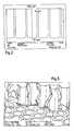
- FIG. 2shows the start of a structurally etched filter element for use with the invention with an aspect ratio greater than 10:1;
- FIG. 3shows an enlargement of a filter element for use with the invention.
- FIG. 4shows a stacked structure of a filter element for use with invention composed of a plurality of semiconductor wafers.
- FIG. 1illustrates a detail of an injection valve 1 in cross section, the detail showing the discharge-side end region of the injection valve 1 .
- the injection valve 1has a housing 2 , into which an insert 6 is pushed on the discharge side.
- the insert 6has a seal 4 on its casing.
- a frustoconical outflow orifice 5 for the fuelis introduced into the insert 6 on the discharge-side end face.
- a valve seatis arranged on the opposite (inflow-side) end face, on which a valve needle 9 of the injection valve 1 can be laid in a seal-forming fashion.
- the remaining surface of the inflow-side end face of the insert 6is shaped in such a way that it has a termination with as low a flow resistance as possible for the fuel inflow duct 8 arranged concentrically around the valve needle 9 .
- a filter element 10is arranged in the inflow duct 8 , likewise concentrically around the valve needle 9 .
- the filter element 10is supported on the outflow side by a perforated plate 11 , preferably made from metal.
- the filter element 10is manufactured from a semiconducting material, preferably from silicon.
- the ducts 3 for the fuel flowing throughare introduced in a simple and cost-effective way by means of one or more etching methods known from semiconductor technology.
- the filter element 10In order to heat the filter element 10 , the latter is supplied with current from outside via a line 7 . In this case, it is expedient to connect the line 7 to the positive pole and the filter element 10 directly to electrical ground via the housing 2 of the injection valve 1 .
- FIG. 2illustrates a microscopic photograph of a filter element, the structure of which is not yet ready-etched fully.
- a three-dimensional image of a completely etched filter elementis illustrated in FIG. 3 .
- the aspect ratio, that is to say the quotient, of half the web width to the corresponding web lengthis greater than 1:10 here.
- FIG. 4illustrates a filter element 10 ′ which is formed from a plurality of semiconductor boards 12 .
- the individual semiconductor boards 12are arranged in alignment one behind the other in the direction of flow of the fuel.
- the individual semiconductor boards 12all have the ducts illustrated in FIGS. 2 and 3.
- the ductsare expediently likewise oriented in alignment one behind the other in the direction of flow of the fuel.
- the semiconductor boards 12have, at their center, a drilled hole 17 which serves for leading through the valve needle 9 .
- Each semiconductor board 12has, on its inner wall facing the valve needle 9 , an electrically insulating valve-needle guide ring 18 .
- the valve-needle guide rings 18expediently seal off the valve needle 9 fluidically in relation to the semiconductor boards 12 .
- the semiconductor boards 12are both surrounded, along the edge, by a ring-like filter housing 13 which, on the one hand, holds the semiconductor boards 12 together and at the same time insulates them thermally in relation to the housing 2 of the injection valve 1 .
- each semiconductor board 12has a closed insulating ring 14 arranged along the edge.
- An insulating ring 14is manufactured from an electrically insulating material and engages in a C-shaped manner around the edge of a semiconductor wafer 12 .
- the insulating ring 14is advantageous, in particular, because less or even no liquid flows through in the edge region of a semiconductor board 12 , so that, without the insulating ring 14 , the edge region of this semiconductor board 12 could heat up excessively. However, due to excessive heating, the resistance in this region would fall, with the result that the current required for heating would then flow out through the edge region.
- an insulating ring 14which face away from the end faces of the semiconductor boards 12 , which are round here, are coated with a metallic conductor, preferably aluminium. That surface of a semiconductor board 12 which is located outside an insulating ring 14 is likewise coated correspondingly.
- the metallic coating of an insulating ring 14 and the coating of the surface of a semiconductor board 12together form a closed conductor layer 15 .
- the outer surfaces of the insulating rings 14do not have any electrically conductive coating.
- the positive poleis expediently applied directly to one of the two outer, that is to say end-face conductor layers 15 , while the other corresponding outer conductor layer 15 is connected to the housing 2 of the injection valve 1 , and consequently to electrical ground, if appropriate via or with the interposition of an electrical leadthrough ring 16 described later.
- the positive poleis expediently applied directly to one of the two outer, that is to say end-face conductor layers 15 , while the other corresponding outer conductor layer 15 is connected to the housing 2 of the injection valve 1 , and consequently to electrical ground, if appropriate via or with the interposition of an electrical leadthrough ring 16 described later.
- the heating of the semiconductor wafers 12 and consequently of the liquid, preferably fuel, flowing throughcan be controlled quantitatively.
- the fuelcan at any time be conditioned in terms of its temperature within the limits predetermined by the system. Improved thermal conditioning gives rise, in turn, to better exhaust-gas behaviour, in particular during the cold-starting phase of an engine.
- a leadthrough ring 16is also arranged on one end face of the filter element 10 and between two semiconductor boards 12 .
- the leadthrough ring 16is manufactured from an electrically conductive material.
- the leadthrough rings 16 arranged between two semiconductor boards 12serve for connecting two semiconductor boards 12 electrically to one another.
- the leadthrough ring 16 arranged on the end face of the filter element 10serves for the electrical connection of the corresponding outer semiconductor board 12 to electrical earth.
Landscapes
- Engineering & Computer Science (AREA)
- Chemical & Material Sciences (AREA)
- Combustion & Propulsion (AREA)
- Mechanical Engineering (AREA)
- General Engineering & Computer Science (AREA)
- Fuel-Injection Apparatus (AREA)
Abstract
Description
Claims (27)
Priority Applications (2)
| Application Number | Priority Date | Filing Date | Title |
|---|---|---|---|
| US10/405,469US6732721B2 (en) | 2000-01-29 | 2003-04-03 | Injection valve |
| US10/405,483US7186351B2 (en) | 2000-01-29 | 2003-04-03 | Injection valve |
Applications Claiming Priority (5)
| Application Number | Priority Date | Filing Date | Title |
|---|---|---|---|
| DE10003935 | 2000-01-29 | ||
| DE10003935 | 2000-01-29 | ||
| DE10003935.9 | 2000-01-29 | ||
| DE10053583ADE10053583B4 (en) | 2000-01-29 | 2000-10-28 | Injector |
| DE10053583 | 2000-10-28 |
Related Child Applications (2)
| Application Number | Title | Priority Date | Filing Date |
|---|---|---|---|
| US10/405,469DivisionUS6732721B2 (en) | 2000-01-29 | 2003-04-03 | Injection valve |
| US10/405,483DivisionUS7186351B2 (en) | 2000-01-29 | 2003-04-03 | Injection valve |
Publications (2)
| Publication Number | Publication Date |
|---|---|
| US20010029980A1 US20010029980A1 (en) | 2001-10-18 |
| US6616066B2true US6616066B2 (en) | 2003-09-09 |
Family
ID=26004104
Family Applications (3)
| Application Number | Title | Priority Date | Filing Date |
|---|---|---|---|
| US09/770,293Expired - Fee RelatedUS6616066B2 (en) | 2000-01-29 | 2001-01-29 | Injection valve |
| US10/405,483Expired - Fee RelatedUS7186351B2 (en) | 2000-01-29 | 2003-04-03 | Injection valve |
| US10/405,469Expired - Fee RelatedUS6732721B2 (en) | 2000-01-29 | 2003-04-03 | Injection valve |
Family Applications After (2)
| Application Number | Title | Priority Date | Filing Date |
|---|---|---|---|
| US10/405,483Expired - Fee RelatedUS7186351B2 (en) | 2000-01-29 | 2003-04-03 | Injection valve |
| US10/405,469Expired - Fee RelatedUS6732721B2 (en) | 2000-01-29 | 2003-04-03 | Injection valve |
Country Status (1)
| Country | Link |
|---|---|
| US (3) | US6616066B2 (en) |
Cited By (3)
| Publication number | Priority date | Publication date | Assignee | Title |
|---|---|---|---|---|
| US6411874B2 (en) | 1997-08-18 | 2002-06-25 | Texas A&M University Systems | Advanced law enforcement and response technology |
| US20040255900A1 (en)* | 2003-06-09 | 2004-12-23 | Darius Mehta | Method and apparatus for controlling liquid-phase fuel penetration distance in a direct-fuel injected engine |
| US20090236448A1 (en)* | 2008-03-18 | 2009-09-24 | Kimberly Burkhard | Fuel injector lower filter |
Families Citing this family (13)
| Publication number | Priority date | Publication date | Assignee | Title |
|---|---|---|---|---|
| US6945472B2 (en)* | 2001-09-04 | 2005-09-20 | Boehringer Ingelheim International Gmbh | Locking-stressing mechanism for a miniaturised high pressuriser |
| US20050263136A1 (en)* | 2002-09-11 | 2005-12-01 | Rigney Shaun T | Fuel delivery system |
| JP4069911B2 (en)* | 2004-08-06 | 2008-04-02 | 株式会社日立製作所 | Heated fuel injection valve |
| US20080060621A1 (en)* | 2006-09-13 | 2008-03-13 | Trapasso David J | Heated fuel injector for cold starting of ethanol-fueled engines |
| US20090121049A1 (en)* | 2007-11-13 | 2009-05-14 | Flynn Vicki A | Internal lower fuel injector filter |
| US20090148802A1 (en)* | 2007-12-05 | 2009-06-11 | Jan Ihle | Process for heating a fluid and an injection molded molding |
| US20090145977A1 (en)* | 2007-12-05 | 2009-06-11 | Jan Ihle | Injection molded nozzle and injector comprising the injection molded nozzle |
| US20090146042A1 (en)* | 2007-12-05 | 2009-06-11 | Jan Ihle | Mold comprising a ptc-ceramic |
| US20090148657A1 (en)* | 2007-12-05 | 2009-06-11 | Jan Ihle | Injection Molded PTC-Ceramics |
| US7973639B2 (en) | 2007-12-05 | 2011-07-05 | Epcos Ag | PTC-resistor |
| US9034210B2 (en)* | 2007-12-05 | 2015-05-19 | Epcos Ag | Feedstock and method for preparing the feedstock |
| DE102013214622A1 (en)* | 2013-07-26 | 2015-01-29 | Robert Bosch Gmbh | Filter device with a signal device with a certain resistance |
| CN105114226A (en)* | 2015-08-13 | 2015-12-02 | 温州职业技术学院 | Electronic control gasoline injector with heating function |
Citations (8)
| Publication number | Priority date | Publication date | Assignee | Title |
|---|---|---|---|---|
| US4898142A (en)* | 1986-05-29 | 1990-02-06 | Texas Instruments Incorporated | Combustion engine with fuel injection system, and a spray valve for such an engine |
| US5048500A (en) | 1990-08-22 | 1991-09-17 | Texas Instruments Incorporated | Internal combustion engine with fuel injectors and heaters |
| US5050569A (en) | 1989-12-22 | 1991-09-24 | Texas Instruments Incorporated | Fuel injection system for an internal combustion engine and fuel heating device therefor |
| DE4121075A1 (en)* | 1991-06-26 | 1993-01-14 | Pierburg Gmbh | Heating element arrangement in combustion engine inlet manifold - comprises filter for mixt. of air and fuel with provision for electric heating by direct current |
| US5179927A (en) | 1990-09-28 | 1993-01-19 | Mercedes-Benz Ag | Injection-type combustion engine with electric spark ignition and a heating system |
| WO1993002284A1 (en) | 1991-07-17 | 1993-02-04 | Texas Instruments Holland B.V. | Injection combustion engine with fuel heating element |
| US5758826A (en) | 1996-03-29 | 1998-06-02 | Siemens Automotive Corporation | Fuel injector with internal heater |
| US5836289A (en)* | 1997-06-10 | 1998-11-17 | Southwest Research Institute | Porous element fuel vaporizer |
Family Cites Families (13)
| Publication number | Priority date | Publication date | Assignee | Title |
|---|---|---|---|---|
| US4477345A (en)* | 1983-01-10 | 1984-10-16 | Stant Inc. | Filter separator with heater |
| DE3327773A1 (en)* | 1983-05-13 | 1984-11-15 | Robert Bosch Gmbh, 7000 Stuttgart | FUEL INJECTION DEVICE IN COMBUSTION CHAMBER |
| US4639748A (en)* | 1985-09-30 | 1987-01-27 | Xerox Corporation | Ink jet printhead with integral ink filter |
| DE3615634A1 (en)* | 1986-05-09 | 1987-11-12 | Bosch Gmbh Robert | DEVICE FOR INJECTING FUEL INTO THE COMBUSTION CHAMBER OF AN INTERNAL COMBUSTION ENGINE |
| US5054458A (en)* | 1986-05-29 | 1991-10-08 | Texas Instruments Incorporated | Combustion engine with fuel injection system, and a spray valve fo r such an engine |
| US5017285A (en)* | 1989-06-28 | 1991-05-21 | Stanadyne Automotive Corp. | Fuel filter and cartridge assembly |
| AU635322B2 (en)* | 1989-09-18 | 1993-03-18 | Canon Kabushiki Kaisha | Liquid jet recording head and liquid jet recording apparatus having same |
| GB9109832D0 (en)* | 1991-05-07 | 1991-06-26 | Ellis Glynn A | Saw blade machining system |
| US5655212A (en)* | 1993-03-12 | 1997-08-05 | Micropyretics Heaters International, Inc. | Porous membranes |
| US5400969A (en)* | 1993-09-20 | 1995-03-28 | Keene; Christopher M. | Liquid vaporizer and diffuser |
| NL9401260A (en)* | 1993-11-12 | 1995-06-01 | Cornelis Johannes Maria Van Ri | Membrane for microfiltration, ultrafiltration, gas separation and catalysis, method for manufacturing such a membrane, mold for manufacturing such a membrane, as well as various separation systems comprising such a membrane. |
| US5692723A (en)* | 1995-06-06 | 1997-12-02 | Sagem-Lucas, Inc. | Electromagnetically actuated disc-type valve |
| US6817708B2 (en)* | 2002-10-29 | 2004-11-16 | Xerox Corporation | Conical or cylindrical laser ablated filter |
- 2001
- 2001-01-29USUS09/770,293patent/US6616066B2/ennot_activeExpired - Fee Related
- 2003
- 2003-04-03USUS10/405,483patent/US7186351B2/ennot_activeExpired - Fee Related
- 2003-04-03USUS10/405,469patent/US6732721B2/ennot_activeExpired - Fee Related
Patent Citations (9)
| Publication number | Priority date | Publication date | Assignee | Title |
|---|---|---|---|---|
| US4898142A (en)* | 1986-05-29 | 1990-02-06 | Texas Instruments Incorporated | Combustion engine with fuel injection system, and a spray valve for such an engine |
| US5050569A (en) | 1989-12-22 | 1991-09-24 | Texas Instruments Incorporated | Fuel injection system for an internal combustion engine and fuel heating device therefor |
| US5048500A (en) | 1990-08-22 | 1991-09-17 | Texas Instruments Incorporated | Internal combustion engine with fuel injectors and heaters |
| EP0472417A1 (en) | 1990-08-22 | 1992-02-26 | Texas Instruments Incorporated | Internal combustion engine with fuel injectors and heaters |
| US5179927A (en) | 1990-09-28 | 1993-01-19 | Mercedes-Benz Ag | Injection-type combustion engine with electric spark ignition and a heating system |
| DE4121075A1 (en)* | 1991-06-26 | 1993-01-14 | Pierburg Gmbh | Heating element arrangement in combustion engine inlet manifold - comprises filter for mixt. of air and fuel with provision for electric heating by direct current |
| WO1993002284A1 (en) | 1991-07-17 | 1993-02-04 | Texas Instruments Holland B.V. | Injection combustion engine with fuel heating element |
| US5758826A (en) | 1996-03-29 | 1998-06-02 | Siemens Automotive Corporation | Fuel injector with internal heater |
| US5836289A (en)* | 1997-06-10 | 1998-11-17 | Southwest Research Institute | Porous element fuel vaporizer |
Cited By (4)
| Publication number | Priority date | Publication date | Assignee | Title |
|---|---|---|---|---|
| US6411874B2 (en) | 1997-08-18 | 2002-06-25 | Texas A&M University Systems | Advanced law enforcement and response technology |
| US20040255900A1 (en)* | 2003-06-09 | 2004-12-23 | Darius Mehta | Method and apparatus for controlling liquid-phase fuel penetration distance in a direct-fuel injected engine |
| US7017547B2 (en)* | 2003-06-09 | 2006-03-28 | Southwest Res Inst | Method and apparatus for controlling liquid-phase fuel penetration distance in a direct-fuel injected engine |
| US20090236448A1 (en)* | 2008-03-18 | 2009-09-24 | Kimberly Burkhard | Fuel injector lower filter |
Also Published As
| Publication number | Publication date |
|---|---|
| US20010029980A1 (en) | 2001-10-18 |
| US20030183210A1 (en) | 2003-10-02 |
| US20030192960A1 (en) | 2003-10-16 |
| US6732721B2 (en) | 2004-05-11 |
| US7186351B2 (en) | 2007-03-06 |
Similar Documents
| Publication | Publication Date | Title |
|---|---|---|
| US6616066B2 (en) | Injection valve | |
| US3868939A (en) | Fuel injection system especially for cold starting and warming up externally ignited internal combustion engines | |
| US4898142A (en) | Combustion engine with fuel injection system, and a spray valve for such an engine | |
| US7158718B2 (en) | Electric heating device | |
| US4818842A (en) | Diesel fuel heater | |
| KR100707124B1 (en) | Fuel injectors for internal combustion engines | |
| US20020185485A1 (en) | Multi-layer ceramic heater | |
| US6396028B1 (en) | Multi-layer ceramic heater | |
| KR101031199B1 (en) | Method and apparatus for providing a gas mixture | |
| US6851311B2 (en) | Thermal-type flow meter with bypass passage | |
| WO1995008395A1 (en) | Liquid vaporizer and diffuser | |
| KR101025063B1 (en) | Capillary Fuel Injector with Metering Valve for Internal Combustion Engine | |
| US3955538A (en) | Fuel reforming system for an internal combustion engine | |
| JPH0861167A (en) | Fuel atomizer | |
| US4361125A (en) | Fuel evaporator for internal combustion engine | |
| EP2108809A2 (en) | Heating device for fuel feeding ducts, fuel feeding duct and combustion engine. | |
| JPH0849625A (en) | Fuel heater heating high-pressure liquid fuel in injection type internal combustion engine and fuel injector for internal combustion engine | |
| JPS6240542B2 (en) | ||
| AU2004205881B2 (en) | Internal combustion engine transient fuel control | |
| CN101889138B (en) | Injection molding nozzle and syringe including injection molding nozzle | |
| DE112013003801B4 (en) | Thermal air flow rate sensor | |
| JP3225176B2 (en) | LPG fuel heating device | |
| DE10053583A1 (en) | Injector | |
| JPH08200168A (en) | Fuel gasifying device, fuel feeding device, and fuel gasifying method | |
| EP1978239B1 (en) | Multiple capillary fuel injector for an internal combustion engine |
Legal Events
| Date | Code | Title | Description |
|---|---|---|---|
| AS | Assignment | Owner name:DAIMLERCHRYSLER AG, GERMANY Free format text:ASSIGNMENT OF ASSIGNORS INTEREST;ASSIGNORS:GUETTLER, HERBERT;HOLDER, EBERHARD;KROETZ, GERHARD;AND OTHERS;REEL/FRAME:011872/0900;SIGNING DATES FROM 20010213 TO 20010425 | |
| FEPP | Fee payment procedure | Free format text:PAYOR NUMBER ASSIGNED (ORIGINAL EVENT CODE: ASPN); ENTITY STATUS OF PATENT OWNER: LARGE ENTITY | |
| FPAY | Fee payment | Year of fee payment:4 | |
| AS | Assignment | Owner name:DAIMLER AG, GERMANY Free format text:CHANGE OF NAME;ASSIGNOR:DAIMLERCHRYSLER AG;REEL/FRAME:020976/0889 Effective date:20071019 Owner name:DAIMLER AG,GERMANY Free format text:CHANGE OF NAME;ASSIGNOR:DAIMLERCHRYSLER AG;REEL/FRAME:020976/0889 Effective date:20071019 | |
| FPAY | Fee payment | Year of fee payment:8 | |
| REMI | Maintenance fee reminder mailed | ||
| LAPS | Lapse for failure to pay maintenance fees | ||
| STCH | Information on status: patent discontinuation | Free format text:PATENT EXPIRED DUE TO NONPAYMENT OF MAINTENANCE FEES UNDER 37 CFR 1.362 | |
| FP | Lapsed due to failure to pay maintenance fee | Effective date:20150909 | |
| AS | Assignment | Owner name:DAIMLER AG, GERMANY Free format text:CORRECTIVE ASSIGNMENT TO CORRECT THE APPLICATION NO. 10/567,810 PREVIOUSLY RECORDED ON REEL 020976 FRAME 0889. ASSIGNOR(S) HEREBY CONFIRMS THE CHANGE OF NAME;ASSIGNOR:DAIMLERCHRYSLER AG;REEL/FRAME:053583/0493 Effective date:20071019 |