US6615946B2 - Power plant for electric earth-moving and agricultural vehicles with four-wheel drive - Google Patents
Power plant for electric earth-moving and agricultural vehicles with four-wheel driveDownload PDFInfo
- Publication number
- US6615946B2 US6615946B2US09/507,729US50772900AUS6615946B2US 6615946 B2US6615946 B2US 6615946B2US 50772900 AUS50772900 AUS 50772900AUS 6615946 B2US6615946 B2US 6615946B2
- Authority
- US
- United States
- Prior art keywords
- power plant
- electric
- distribution
- housing
- plant according
- Prior art date
- Legal status (The legal status is an assumption and is not a legal conclusion. Google has not performed a legal analysis and makes no representation as to the accuracy of the status listed.)
- Expired - Lifetime
Links
Images


Classifications
- B—PERFORMING OPERATIONS; TRANSPORTING
- B60—VEHICLES IN GENERAL
- B60K—ARRANGEMENT OR MOUNTING OF PROPULSION UNITS OR OF TRANSMISSIONS IN VEHICLES; ARRANGEMENT OR MOUNTING OF PLURAL DIVERSE PRIME-MOVERS IN VEHICLES; AUXILIARY DRIVES FOR VEHICLES; INSTRUMENTATION OR DASHBOARDS FOR VEHICLES; ARRANGEMENTS IN CONNECTION WITH COOLING, AIR INTAKE, GAS EXHAUST OR FUEL SUPPLY OF PROPULSION UNITS IN VEHICLES
- B60K1/00—Arrangement or mounting of electrical propulsion units
- B60K1/02—Arrangement or mounting of electrical propulsion units comprising more than one electric motor
- B—PERFORMING OPERATIONS; TRANSPORTING
- B60—VEHICLES IN GENERAL
- B60K—ARRANGEMENT OR MOUNTING OF PROPULSION UNITS OR OF TRANSMISSIONS IN VEHICLES; ARRANGEMENT OR MOUNTING OF PLURAL DIVERSE PRIME-MOVERS IN VEHICLES; AUXILIARY DRIVES FOR VEHICLES; INSTRUMENTATION OR DASHBOARDS FOR VEHICLES; ARRANGEMENTS IN CONNECTION WITH COOLING, AIR INTAKE, GAS EXHAUST OR FUEL SUPPLY OF PROPULSION UNITS IN VEHICLES
- B60K1/00—Arrangement or mounting of electrical propulsion units
- B60K1/04—Arrangement or mounting of electrical propulsion units of the electric storage means for propulsion
- B—PERFORMING OPERATIONS; TRANSPORTING
- B60—VEHICLES IN GENERAL
- B60K—ARRANGEMENT OR MOUNTING OF PROPULSION UNITS OR OF TRANSMISSIONS IN VEHICLES; ARRANGEMENT OR MOUNTING OF PLURAL DIVERSE PRIME-MOVERS IN VEHICLES; AUXILIARY DRIVES FOR VEHICLES; INSTRUMENTATION OR DASHBOARDS FOR VEHICLES; ARRANGEMENTS IN CONNECTION WITH COOLING, AIR INTAKE, GAS EXHAUST OR FUEL SUPPLY OF PROPULSION UNITS IN VEHICLES
- B60K17/00—Arrangement or mounting of transmissions in vehicles
- B60K17/34—Arrangement or mounting of transmissions in vehicles for driving both front and rear wheels, e.g. four wheel drive vehicles
- B60K17/344—Arrangement or mounting of transmissions in vehicles for driving both front and rear wheels, e.g. four wheel drive vehicles having a transfer gear
- B—PERFORMING OPERATIONS; TRANSPORTING
- B60—VEHICLES IN GENERAL
- B60L—PROPULSION OF ELECTRICALLY-PROPELLED VEHICLES; SUPPLYING ELECTRIC POWER FOR AUXILIARY EQUIPMENT OF ELECTRICALLY-PROPELLED VEHICLES; ELECTRODYNAMIC BRAKE SYSTEMS FOR VEHICLES IN GENERAL; MAGNETIC SUSPENSION OR LEVITATION FOR VEHICLES; MONITORING OPERATING VARIABLES OF ELECTRICALLY-PROPELLED VEHICLES; ELECTRIC SAFETY DEVICES FOR ELECTRICALLY-PROPELLED VEHICLES
- B60L50/00—Electric propulsion with power supplied within the vehicle
- B60L50/50—Electric propulsion with power supplied within the vehicle using propulsion power supplied by batteries or fuel cells
- B60L50/52—Electric propulsion with power supplied within the vehicle using propulsion power supplied by batteries or fuel cells characterised by DC-motors
- B—PERFORMING OPERATIONS; TRANSPORTING
- B60—VEHICLES IN GENERAL
- B60L—PROPULSION OF ELECTRICALLY-PROPELLED VEHICLES; SUPPLYING ELECTRIC POWER FOR AUXILIARY EQUIPMENT OF ELECTRICALLY-PROPELLED VEHICLES; ELECTRODYNAMIC BRAKE SYSTEMS FOR VEHICLES IN GENERAL; MAGNETIC SUSPENSION OR LEVITATION FOR VEHICLES; MONITORING OPERATING VARIABLES OF ELECTRICALLY-PROPELLED VEHICLES; ELECTRIC SAFETY DEVICES FOR ELECTRICALLY-PROPELLED VEHICLES
- B60L50/00—Electric propulsion with power supplied within the vehicle
- B60L50/50—Electric propulsion with power supplied within the vehicle using propulsion power supplied by batteries or fuel cells
- B60L50/60—Electric propulsion with power supplied within the vehicle using propulsion power supplied by batteries or fuel cells using power supplied by batteries
- B60L50/66—Arrangements of batteries
- B—PERFORMING OPERATIONS; TRANSPORTING
- B60—VEHICLES IN GENERAL
- B60L—PROPULSION OF ELECTRICALLY-PROPELLED VEHICLES; SUPPLYING ELECTRIC POWER FOR AUXILIARY EQUIPMENT OF ELECTRICALLY-PROPELLED VEHICLES; ELECTRODYNAMIC BRAKE SYSTEMS FOR VEHICLES IN GENERAL; MAGNETIC SUSPENSION OR LEVITATION FOR VEHICLES; MONITORING OPERATING VARIABLES OF ELECTRICALLY-PROPELLED VEHICLES; ELECTRIC SAFETY DEVICES FOR ELECTRICALLY-PROPELLED VEHICLES
- B60L58/00—Methods or circuit arrangements for monitoring or controlling batteries or fuel cells, specially adapted for electric vehicles
- B60L58/10—Methods or circuit arrangements for monitoring or controlling batteries or fuel cells, specially adapted for electric vehicles for monitoring or controlling batteries
- B60L58/18—Methods or circuit arrangements for monitoring or controlling batteries or fuel cells, specially adapted for electric vehicles for monitoring or controlling batteries of two or more battery modules
- B60L58/21—Methods or circuit arrangements for monitoring or controlling batteries or fuel cells, specially adapted for electric vehicles for monitoring or controlling batteries of two or more battery modules having the same nominal voltage
- B—PERFORMING OPERATIONS; TRANSPORTING
- B60—VEHICLES IN GENERAL
- B60L—PROPULSION OF ELECTRICALLY-PROPELLED VEHICLES; SUPPLYING ELECTRIC POWER FOR AUXILIARY EQUIPMENT OF ELECTRICALLY-PROPELLED VEHICLES; ELECTRODYNAMIC BRAKE SYSTEMS FOR VEHICLES IN GENERAL; MAGNETIC SUSPENSION OR LEVITATION FOR VEHICLES; MONITORING OPERATING VARIABLES OF ELECTRICALLY-PROPELLED VEHICLES; ELECTRIC SAFETY DEVICES FOR ELECTRICALLY-PROPELLED VEHICLES
- B60L7/00—Electrodynamic brake systems for vehicles in general
- B60L7/10—Dynamic electric regenerative braking
- B60L7/12—Dynamic electric regenerative braking for vehicles propelled by DC motors
- B—PERFORMING OPERATIONS; TRANSPORTING
- B60—VEHICLES IN GENERAL
- B60L—PROPULSION OF ELECTRICALLY-PROPELLED VEHICLES; SUPPLYING ELECTRIC POWER FOR AUXILIARY EQUIPMENT OF ELECTRICALLY-PROPELLED VEHICLES; ELECTRODYNAMIC BRAKE SYSTEMS FOR VEHICLES IN GENERAL; MAGNETIC SUSPENSION OR LEVITATION FOR VEHICLES; MONITORING OPERATING VARIABLES OF ELECTRICALLY-PROPELLED VEHICLES; ELECTRIC SAFETY DEVICES FOR ELECTRICALLY-PROPELLED VEHICLES
- B60L2200/00—Type of vehicles
- B60L2200/40—Working vehicles
- B—PERFORMING OPERATIONS; TRANSPORTING
- B60—VEHICLES IN GENERAL
- B60L—PROPULSION OF ELECTRICALLY-PROPELLED VEHICLES; SUPPLYING ELECTRIC POWER FOR AUXILIARY EQUIPMENT OF ELECTRICALLY-PROPELLED VEHICLES; ELECTRODYNAMIC BRAKE SYSTEMS FOR VEHICLES IN GENERAL; MAGNETIC SUSPENSION OR LEVITATION FOR VEHICLES; MONITORING OPERATING VARIABLES OF ELECTRICALLY-PROPELLED VEHICLES; ELECTRIC SAFETY DEVICES FOR ELECTRICALLY-PROPELLED VEHICLES
- B60L2220/00—Electrical machine types; Structures or applications thereof
- B60L2220/40—Electrical machine applications
- B60L2220/46—Wheel motors, i.e. motor connected to only one wheel
- B—PERFORMING OPERATIONS; TRANSPORTING
- B60—VEHICLES IN GENERAL
- B60L—PROPULSION OF ELECTRICALLY-PROPELLED VEHICLES; SUPPLYING ELECTRIC POWER FOR AUXILIARY EQUIPMENT OF ELECTRICALLY-PROPELLED VEHICLES; ELECTRODYNAMIC BRAKE SYSTEMS FOR VEHICLES IN GENERAL; MAGNETIC SUSPENSION OR LEVITATION FOR VEHICLES; MONITORING OPERATING VARIABLES OF ELECTRICALLY-PROPELLED VEHICLES; ELECTRIC SAFETY DEVICES FOR ELECTRICALLY-PROPELLED VEHICLES
- B60L2260/00—Operating Modes
- B60L2260/20—Drive modes; Transition between modes
- B60L2260/28—Four wheel or all wheel drive
- Y—GENERAL TAGGING OF NEW TECHNOLOGICAL DEVELOPMENTS; GENERAL TAGGING OF CROSS-SECTIONAL TECHNOLOGIES SPANNING OVER SEVERAL SECTIONS OF THE IPC; TECHNICAL SUBJECTS COVERED BY FORMER USPC CROSS-REFERENCE ART COLLECTIONS [XRACs] AND DIGESTS
- Y02—TECHNOLOGIES OR APPLICATIONS FOR MITIGATION OR ADAPTATION AGAINST CLIMATE CHANGE
- Y02P—CLIMATE CHANGE MITIGATION TECHNOLOGIES IN THE PRODUCTION OR PROCESSING OF GOODS
- Y02P90/00—Enabling technologies with a potential contribution to greenhouse gas [GHG] emissions mitigation
- Y02P90/60—Electric or hybrid propulsion means for production processes
- Y—GENERAL TAGGING OF NEW TECHNOLOGICAL DEVELOPMENTS; GENERAL TAGGING OF CROSS-SECTIONAL TECHNOLOGIES SPANNING OVER SEVERAL SECTIONS OF THE IPC; TECHNICAL SUBJECTS COVERED BY FORMER USPC CROSS-REFERENCE ART COLLECTIONS [XRACs] AND DIGESTS
- Y02—TECHNOLOGIES OR APPLICATIONS FOR MITIGATION OR ADAPTATION AGAINST CLIMATE CHANGE
- Y02T—CLIMATE CHANGE MITIGATION TECHNOLOGIES RELATED TO TRANSPORTATION
- Y02T10/00—Road transport of goods or passengers
- Y02T10/60—Other road transportation technologies with climate change mitigation effect
- Y02T10/64—Electric machine technologies in electromobility
- Y—GENERAL TAGGING OF NEW TECHNOLOGICAL DEVELOPMENTS; GENERAL TAGGING OF CROSS-SECTIONAL TECHNOLOGIES SPANNING OVER SEVERAL SECTIONS OF THE IPC; TECHNICAL SUBJECTS COVERED BY FORMER USPC CROSS-REFERENCE ART COLLECTIONS [XRACs] AND DIGESTS
- Y02—TECHNOLOGIES OR APPLICATIONS FOR MITIGATION OR ADAPTATION AGAINST CLIMATE CHANGE
- Y02T—CLIMATE CHANGE MITIGATION TECHNOLOGIES RELATED TO TRANSPORTATION
- Y02T10/00—Road transport of goods or passengers
- Y02T10/60—Other road transportation technologies with climate change mitigation effect
- Y02T10/70—Energy storage systems for electromobility, e.g. batteries
Definitions
- the present inventionrelates to a power plant for electric earth-moving and agricultural vehicles with four-wheel drive.
- Vehicles with a hydraulic drive controlled by a pump which is driven by an internal-combustion engineare also known for earth-moving and agricultural work: in particular, some vehicles can be fitted, at the front or at the rear, with buckets, loading shovels, blades, lifting forks, excavators, mills, drills, rotating brushes or equipment of any kind which is actuated hydraulically.
- Power plants for vehicles of this typeare extremely effective, but when used in enclosed spaces, such as mines, basements, ship holds, industrial buildings, historical city centers, cemeteries or the like, they have the drawback that their internal-combustion engines emit exhaust gases and produce noise at levels which are particularly unwanted in such environments.
- earth-moving vehiclesmust be able to travel for significant stretches on roads, including unpaved roads, without stations for recharging or replacing the batteries.
- the aim of the present inventionis to provide a power plant for electric earth-moving and agricultural vehicles with four-wheel drive which can travel over significant distances on roads, can operate without emitting toxic gases, can be fitted with equipment of any kind which can be actuated hydraulically and has a significant operating range.
- an object of the present inventionis to provide a structure which is simple, relatively easy to provide in practice, safe in use, effective in operation and relatively modest in cost.
- a power plant for electric earth-moving and agricultural vehicles with four-wheel drivecharacterized in that it comprises a supporting chassis, an electric motor drive for the driving wheels of the vehicle which comprises a gear-type reduction and distribution unit which is installed in a housing which is rigidly coupled to said chassis, at least two electric motors whose body is fixed to said housing, a front longitudinal distribution shaft and a rear longitudinal distribution shaft which protrude from said housing, two differentials which are fitted at the ends of said distribution shafts and from which a front axle and a rear axle respectively protrude for respective pairs of driving wheels, at least one of said axles being provided with steering elements, and an assembly for the oscillating support of said front axle which is fixed, in a downward region, to the front end of said supporting chassis.
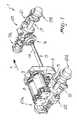
- FIG. 1is a schematic perspective view of the power plant for electric earth-moving and agricultural vehicles with four-wheel drive according to the invention
- FIG. 2is side view of the power plant
- FIG. 3is a top view of the power plant
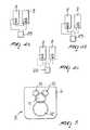
- FIGS. 4 a- 4 care block diagrams of the electric power supply of the travel motor drive assembly of the vehicle with two electric motors in various planned coupling options.
- FIG. 5is a front view of a gear-type distribution and reduction unit of the power plant.
- the reference numeral 1generally designates a power plant for electric earth-moving and agricultural vehicles with four-wheel drive according to the invention, whose usual direction of forward travel has been designated by the arrow A.
- the power plant 1comprises a supporting chassis 2 , an electric motor drive 3 for driving wheels of the vehicle, and an assembly 4 for the oscillating support of the front axle of the vehicle which is fixed, in a downward region, to the front end of the supporting chassis.
- the motor drive 3comprises a gear-type reduction and distribution unit 5 which is installed in a housing 6 which is rigidly coupled to the chassis: the reference numerals 8 and 9 designate two electric motors whose bodies are fixed to the housing 6 : the horizontal output shafts of the motors 8 and 9 support respective toothed sprockets 10 which, optionally by means of an interposed idler gear 11 , drive a gear 12 which is keyed onto a front longitudinal distribution shaft 14 and onto a rear longitudinal distribution shaft 13 , both of the shafts protruding from the housing.
- the shafts 13 and 14can be either a single rigid shaft whose two ends protrude from the housing or two separate shafts which are mutually connected by a differential of the self-locking or manually lockable type for road travel.
- Two differentials 15 and 16are installed at the respective ends of the two shafts 13 and 14 , and a front axle 17 and a rear axle 18 protrude respectively from the differentials 14 , 13 and are meant for respective pairs of hubs and respective driving wheels 19 a , 19 b and 20 a , 20 b .
- At least one of the axlesis provided with steering elements: in the particular case shown, both axles have respective conventional steering elements 21 and 22 .
- the supporting chassis 2in a median and lower position, there is a transversely open tunnel 24 for installing a set of batteries B.
- the tunnel 24forms a box-like compartment which can be a single through compartment or can be constituted by a pair of compartment sections separated by a duct for the passage of the front distribution shaft.
- the chassisis provided with additional compartments for arranging a second set of batteries, for example above the front wheels.
- the shafts 13 and 14have, at their ends, respective universal joints 26 a , 26 b , 27 a and 27 b.
- the battery sets Bare of the type known as gel or absorbed-acid batteries, and are adapted to operate even with high inclinations and under intense mechanical stress.
- a disk 28is fixed at right angles to one of the distribution shafts, particularly to the front one, and is adapted to be braked by two braking shoes 29 a and 29 b.
- the vehicleis provided with a platform 30 on which an electricity-generating unit can be carried in order to recharge the battery sets: the unit can be deposited in an area where it can operate without causing pollution problems and can be connected, even by means of a long cable, to the vehicle in order to recharge the batteries during operation.
- the power plant for electric earth-moving and agricultural vehicles with four-wheel drive according to the inventionis capable of covering even long stretches on roads, since the travel motors can be supplied by any one of the battery sets so as to increase speed or range according to requirements; moreover, it can operate without emitting toxic gases and can be fitted with equipment of any kind which can be actuated hydraulically.
Landscapes
- Engineering & Computer Science (AREA)
- Transportation (AREA)
- Mechanical Engineering (AREA)
- Power Engineering (AREA)
- Chemical & Material Sciences (AREA)
- Combustion & Propulsion (AREA)
- Life Sciences & Earth Sciences (AREA)
- Sustainable Development (AREA)
- Sustainable Energy (AREA)
- Arrangement Or Mounting Of Propulsion Units For Vehicles (AREA)
- Arrangement And Driving Of Transmission Devices (AREA)
Abstract
Description
The present invention relates to a power plant for electric earth-moving and agricultural vehicles with four-wheel drive.
Vehicles with a hydraulic drive controlled by a pump which is driven by an internal-combustion engine are also known for earth-moving and agricultural work: in particular, some vehicles can be fitted, at the front or at the rear, with buckets, loading shovels, blades, lifting forks, excavators, mills, drills, rotating brushes or equipment of any kind which is actuated hydraulically. Power plants for vehicles of this type are extremely effective, but when used in enclosed spaces, such as mines, basements, ship holds, industrial buildings, historical city centers, cemeteries or the like, they have the drawback that their internal-combustion engines emit exhaust gases and produce noise at levels which are particularly unwanted in such environments.
In practice, there is the need for vehicles which reduce the coefficients of acoustic and chemical aggressiveness and which in giving broad assurances of environment-friendliness have a gentle impact on the user and on the citizens involved.
On the other hand, differently from battery-powered electric-drive vehicles known as fork-lift trucks, which are meant to usually work on level ground and on the same site, earth-moving vehicles must be able to travel for significant stretches on roads, including unpaved roads, without stations for recharging or replacing the batteries.
The aim of the present invention is to provide a power plant for electric earth-moving and agricultural vehicles with four-wheel drive which can travel over significant distances on roads, can operate without emitting toxic gases, can be fitted with equipment of any kind which can be actuated hydraulically and has a significant operating range.
Within the scope of this aim, an object of the present invention is to provide a structure which is simple, relatively easy to provide in practice, safe in use, effective in operation and relatively modest in cost.
This aim, this object and others which will become apparent hereinafter are achieved by a power plant for electric earth-moving and agricultural vehicles with four-wheel drive according to the present invention, characterized in that it comprises a supporting chassis, an electric motor drive for the driving wheels of the vehicle which comprises a gear-type reduction and distribution unit which is installed in a housing which is rigidly coupled to said chassis, at least two electric motors whose body is fixed to said housing, a front longitudinal distribution shaft and a rear longitudinal distribution shaft which protrude from said housing, two differentials which are fitted at the ends of said distribution shafts and from which a front axle and a rear axle respectively protrude for respective pairs of driving wheels, at least one of said axles being provided with steering elements, and an assembly for the oscillating support of said front axle which is fixed, in a downward region, to the front end of said supporting chassis.
Further characteristics and advantages of the present invention will become apparent from the following detailed description of a preferred but not exclusive embodiment of a power plant for electric earth-moving and agricultural vehicles with four-wheel drive according to the invention, illustrated only by way of non-limitative example in the accompanying drawings, wherein:
FIG. 1 is a schematic perspective view of the power plant for electric earth-moving and agricultural vehicles with four-wheel drive according to the invention;
FIG. 2 is side view of the power plant;
FIG. 3 is a top view of the power plant;
FIGS. 4a-4care block diagrams of the electric power supply of the travel motor drive assembly of the vehicle with two electric motors in various planned coupling options; and
FIG. 5 is a front view of a gear-type distribution and reduction unit of the power plant.
With particular reference to the above figures, the reference numeral1 generally designates a power plant for electric earth-moving and agricultural vehicles with four-wheel drive according to the invention, whose usual direction of forward travel has been designated by the arrow A.
The power plant1 comprises a supporting chassis2, anelectric motor drive 3 for driving wheels of the vehicle, and an assembly4 for the oscillating support of the front axle of the vehicle which is fixed, in a downward region, to the front end of the supporting chassis.
Themotor drive 3 comprises a gear-type reduction anddistribution unit 5 which is installed in ahousing 6 which is rigidly coupled to the chassis: thereference numerals motors respective toothed sprockets 10 which, optionally by means of an interposedidler gear 11, drive agear 12 which is keyed onto a frontlongitudinal distribution shaft 14 and onto a rearlongitudinal distribution shaft 13, both of the shafts protruding from the housing.
Theshafts
Twodifferentials shafts front axle 17 and arear axle 18 protrude respectively from thedifferentials respective driving wheels conventional steering elements
Advantageously, in the supporting chassis2, in a median and lower position, there is a transverselyopen tunnel 24 for installing a set of batteries B.
Thetunnel 24 forms a box-like compartment which can be a single through compartment or can be constituted by a pair of compartment sections separated by a duct for the passage of the front distribution shaft.
Conveniently, the chassis is provided with additional compartments for arranging a second set of batteries, for example above the front wheels.
As shown above, there are twoelectric motors distribution shafts control unit 25, to the set of batteries B in series or individually or in parallel, in order to be able to provide incrementally higher speeds: advantageously, theshafts universal joints 26a,26b,27aand27b.
In another embodiment there are four electric motors: two are associated with a front distribution and reduction unit and two are associated with a rear distribution and reduction unit.
The battery sets B are of the type known as gel or absorbed-acid batteries, and are adapted to operate even with high inclinations and under intense mechanical stress.
Adisk 28 is fixed at right angles to one of the distribution shafts, particularly to the front one, and is adapted to be braked by two braking shoes29aand29b.
Advantageously, the vehicle is provided with aplatform 30 on which an electricity-generating unit can be carried in order to recharge the battery sets: the unit can be deposited in an area where it can operate without causing pollution problems and can be connected, even by means of a long cable, to the vehicle in order to recharge the batteries during operation.
The power plant for electric earth-moving and agricultural vehicles with four-wheel drive according to the invention is capable of covering even long stretches on roads, since the travel motors can be supplied by any one of the battery sets so as to increase speed or range according to requirements; moreover, it can operate without emitting toxic gases and can be fitted with equipment of any kind which can be actuated hydraulically.
It has thus been shown that the invention achieves the intended aim and object.
The invention thus conceived is susceptible of numerous modifications and variations, all of which are within the scope of the inventive concept.
All the details may furthermore be replaced with other technically equivalent ones.
In practice, the materials used, as well as the shapes and the dimensions, may be any according to requirements without thereby abandoning the scope of the protection of the appended claims.
Claims (8)
1. A power plant for electric earth-moving vehicles with four wheel drive, comprising a supporting chassis, an electric motor drive for driving wheels of the vehicle, said motor drive comprising a gear-type reduction and distribution unit which is installed in a housing which is rigidly coupled to said chassis, a front longitudinal distribution shaft and a rear longitudinal distribution shaft which protrude from said housing, at least two electric traction motors whose body is fixed to said housing such that the two motors are connected to said distribution shafts, two differentials which are fitted at the ends of said distribution shafts and from which a front axle and a rear axle respectively protrude for respective pairs of said driving wheels, at least one of said axles being provided with steering elements; a supporting element for an oscillating support of said front axle which is fixed, in a downward region, to a front end of said supporting chassis; and a control unit for connecting in series or individually or in parallel said at least two electric traction motors to an electric power supply, in order to drive said distribution shafts and to provide four wheel drive at incrementally higher speeds, depending on whether said control unit connects said at least two electric traction motors in series or individually or in parallel to said electric power supply.
2. The power plant according toclaim 1 , wherein said electric motors are connected to said distribution shafts by means of said distribution and reduction unit and can be connected, by means of said control unit, to a set of batteries in series or individually or in parallel which constitute said electric power supply.
3. The power plant according toclaim 1 , wherein said front and rear longitudinal distribution shafts are a single rigid shaft whose two ends protrude from said housing.
4. The power plant according toclaim 1 , wherein said front and rear longitudinal distribution shafts are separate and are mutually connectable.
5. The power plant according toclaim 1 , wherein said supporting chassis has, in a median position and in a downward region, a transversely open tunnel for inserting a first set of batteries.
6. The power plant according toclaim 5 , wherein said supporting chassis has further compartments arranged substantially above the front wheels for a second set of batteries.
7. The power plant according toclaim 6 , wherein said first and second battery sets are of a type known as gel-cell or absorbed-acid batteries.
8. The power plant according toclaim 1 , wherein a disk is fixed at right angles to one of said distribution shafts and is adapted to be braked by a pair of braking shoes.
Applications Claiming Priority (3)
| Application Number | Priority Date | Filing Date | Title |
|---|---|---|---|
| ITB099A000077 | 1999-02-24 | ||
| ITBO99A0077 | 1999-02-24 | ||
| IT1999BO000077AIT1309008B1 (en) | 1999-02-24 | 1999-02-24 | PROPULSION GROUP FOR FOUR-WHEEL ELECTRIC VEHICLES FOR EARTH-MOVING AND AGRICULTURE |
Publications (2)
| Publication Number | Publication Date |
|---|---|
| US20020074177A1 US20020074177A1 (en) | 2002-06-20 |
| US6615946B2true US6615946B2 (en) | 2003-09-09 |
Family
ID=11343734
Family Applications (1)
| Application Number | Title | Priority Date | Filing Date |
|---|---|---|---|
| US09/507,729Expired - LifetimeUS6615946B2 (en) | 1999-02-24 | 2000-02-22 | Power plant for electric earth-moving and agricultural vehicles with four-wheel drive |
Country Status (5)
| Country | Link |
|---|---|
| US (1) | US6615946B2 (en) |
| EP (1) | EP1031452B1 (en) |
| CA (1) | CA2299802C (en) |
| DE (1) | DE60013340T2 (en) |
| IT (1) | IT1309008B1 (en) |
Cited By (28)
| Publication number | Priority date | Publication date | Assignee | Title |
|---|---|---|---|---|
| US20030116371A1 (en)* | 2001-12-25 | 2003-06-26 | Fuji Jukogyo Kabushiki Kaisha | Differential mechanism for a vehicle |
| US20040251069A1 (en)* | 2003-06-07 | 2004-12-16 | Scott Austin | 4 x 4 Conversion kit |
| US20060054368A1 (en)* | 2004-09-16 | 2006-03-16 | Varela Tomaz D | Electric drive axle assembly with independent dual motors |
| US20060116233A1 (en)* | 2004-11-30 | 2006-06-01 | Mircea Gradu | Electric drive axle |
| US20060191168A1 (en)* | 2005-02-28 | 2006-08-31 | Caterpillar Inc. | Multi-motor drive system for a work machine |
| US7134517B1 (en)* | 2003-02-10 | 2006-11-14 | Kaiser Clements J | Dual electric motor four wheel drive personnel carrier |
| US20070114080A1 (en)* | 2003-02-10 | 2007-05-24 | Kaiser Clenemts J | Dual electric motor four wheel drive personnel carrier |
| US20080115995A1 (en)* | 2006-11-17 | 2008-05-22 | Holland Ronald A | Anti-lock brake |
| US7497285B1 (en)* | 2007-11-15 | 2009-03-03 | Vladimir Radev | Hybrid electric vehicle |
| US20110139522A1 (en)* | 2008-08-22 | 2011-06-16 | Aisin Aw Co., Ltd. | Vehicle drive device |
| US20120103706A1 (en)* | 2010-10-29 | 2012-05-03 | Honda Motor Co., Ltd. | Electric vehicle |
| US20130168174A1 (en)* | 2011-12-29 | 2013-07-04 | Kawasaki Jukogyo Kabushiki Kaisha | Hybrid Utility Vehicle |
| US9096126B2 (en) | 2011-12-05 | 2015-08-04 | Dr. Ing. H.C.F. Porsche Aktiengesellschaft | Drive train of a purely electrically all-wheel drivable motor vehicle |
| US9199527B2 (en) | 2011-12-05 | 2015-12-01 | Dr. Ing. H.C. F. Porsche Aktiengesellschaft | Drive train of a purely electrically all-wheel drivable motor vehicle |
| US9221334B2 (en) | 2011-12-22 | 2015-12-29 | Dr. Ing. H.C. F. Porsche Aktiengesellschaft | Drive train of a solely electrically driven motor vehicle having two electric motors |
| US9457658B2 (en) | 2011-12-05 | 2016-10-04 | Dr. Ing. h.c.F. Posche Aktiengesellschaft | Drive train of a purely electrically all-wheel drivable motor vehicle |
| US20160311310A1 (en)* | 2013-12-11 | 2016-10-27 | Liebherr-Components Biberach Gmbh | Self-propelled work machine |
| US9484602B1 (en) | 2013-08-22 | 2016-11-01 | OSC Manufacturing & Equipment Services, Inc. | Light tower having a battery housing |
| US10029565B1 (en) | 2011-02-24 | 2018-07-24 | Hydro-Gear Limited Partnership | Electric transaxles with steerable axles |
| US10118477B2 (en)* | 2016-06-14 | 2018-11-06 | Polaris Industries Inc. | Hybrid utility vehicle |
| US20190315216A1 (en)* | 2016-12-14 | 2019-10-17 | Dana Heavy Vehicle Systems Group, Llc | Hybrid electric vehicle axle with two motors |
| US10749224B2 (en) | 2015-08-17 | 2020-08-18 | OSC Manufacturing & Equipment Services, Inc. | Rechargeable battery power system having a battery with multiple uses |
| US10780770B2 (en) | 2018-10-05 | 2020-09-22 | Polaris Industries Inc. | Hybrid utility vehicle |
| US10814875B2 (en) | 2019-01-31 | 2020-10-27 | Cnh Industrial Canada, Ltd. | Regenerative braking system for an implement |
| US11370266B2 (en) | 2019-05-16 | 2022-06-28 | Polaris Industries Inc. | Hybrid utility vehicle |
| US11407307B2 (en)* | 2020-03-23 | 2022-08-09 | Arvinmeritor Technology, Llc | Drive axle system having multiple electric motors |
| EP4227148A4 (en)* | 2020-12-15 | 2024-09-18 | Zhejiang Geely Holding Group Co., Ltd. | BATTERY CHANGE TRANSPORT VEHICLE WITHOUT INTERMEDIATE DRIVE SHAFT |
| US20240336121A1 (en)* | 2023-04-04 | 2024-10-10 | Toyota Motor Engineering & Manufacturing North America, Inc. | Dual Electric Motor Assembly Systems and Methods |
Families Citing this family (20)
| Publication number | Priority date | Publication date | Assignee | Title |
|---|---|---|---|---|
| DE102004043808B4 (en)* | 2004-09-08 | 2007-11-22 | Holmer Maschinenbau Gmbh | driving means |
| DE102007021733B4 (en)* | 2007-05-09 | 2011-03-10 | Agco Gmbh | Drive arrangement for vehicles with at least two drivable vehicle axles |
| US9162558B2 (en)* | 2009-06-15 | 2015-10-20 | Polaris Industries Inc. | Electric vehicle |
| DE102009051124B4 (en) | 2009-10-28 | 2017-06-22 | Schaeffler Technologies AG & Co. KG | Drive system for an electric cycle vehicle |
| DE102010010578B4 (en)* | 2010-03-08 | 2014-03-20 | Mkf Gmbh & Co. Kg | Hydrostatic-electric drive, industrial truck with such a drive |
| DE102011112958A1 (en)* | 2011-09-13 | 2013-03-14 | GM Global Technology Operations LLC (n. d. Gesetzen des Staates Delaware) | Brake assembly for motor vehicle, particularly small- or micro assembly or electric vehicle, has brake body that is arranged in drive train of motor vehicle, where brake body is arranged relative to force flow direction before hub |
| DE202011109790U1 (en) | 2011-12-05 | 2012-05-07 | Dr. Ing. H.C. F. Porsche Aktiengesellschaft | Powertrain of a purely electric allradbetreibbaren motor vehicle |
| DE102012101209A1 (en) | 2012-02-15 | 2013-08-22 | Dr. Ing. H.C. F. Porsche Aktiengesellschaft | Drive train of a purely electrically driven motor vehicle |
| DE102012101984A1 (en) | 2012-03-09 | 2013-09-12 | Dr. Ing. H.C. F. Porsche Aktiengesellschaft | Drive train for electrically driven motor vehicle, has electric machine, which is connected to differential by clutch and subtransmission for driving two axle portions of axle, where axle portions are connected with left- and right wheel |
| DE102012011573A1 (en)* | 2012-06-13 | 2013-12-19 | Claas Selbstfahrende Erntemaschinen Gmbh | Steering axle for agricultural vehicles |
| MY176183A (en)* | 2013-08-29 | 2020-07-24 | Kpit Tech Ltd | Retrofit system for converting a vehicle into one of a hybrid electric vehicle and electric vehicle (ev) |
| CN105584343A (en)* | 2014-10-22 | 2016-05-18 | 上海馨联动力系统有限公司 | Blade electric vehicle power assembly with double permanent magnet synchronous motors |
| DE102017214745A1 (en)* | 2017-08-23 | 2019-02-28 | Zf Friedrichshafen Ag | Central drive unit for a vehicle and drive arrangement with the central drive unit |
| DE102017219994B4 (en) | 2017-11-10 | 2019-06-06 | Zf Friedrichshafen Ag | Drive axle for an electrically driven work machine |
| DE102018206206A1 (en)* | 2018-04-23 | 2019-10-24 | Zf Friedrichshafen Ag | Electrically powered working machine |
| DE102018206403A1 (en)* | 2018-04-25 | 2019-10-31 | Zf Friedrichshafen Ag | Drive arrangement for a wheeled excavator |
| JP7097806B2 (en)* | 2018-12-27 | 2022-07-08 | 株式会社クボタ | Electric work vehicle |
| GB2582261B (en)* | 2019-03-01 | 2023-06-21 | Bamford Excavators Ltd | Working machine |
| SE543268C2 (en)* | 2019-03-08 | 2020-11-10 | Scania Cv Ab | A powertrain for a vehicle and a vehicle comprising a powertrain |
| US11691491B2 (en) | 2019-08-20 | 2023-07-04 | Designwerk Technologies Ag | Drivetrain |
Citations (26)
| Publication number | Priority date | Publication date | Assignee | Title |
|---|---|---|---|---|
| US1254057A (en)* | 1916-03-10 | 1918-01-22 | William J P Moore | Control mechanism for automobiles and other vehicles and machines. |
| US2944830A (en) | 1958-05-15 | 1960-07-12 | Osborne Charles Vernon | Four wheel steering mechanism for a mine car |
| US3771032A (en)* | 1972-06-07 | 1973-11-06 | B Hender | Plural electric motor control systems |
| US3799284A (en)* | 1971-10-30 | 1974-03-26 | B Hender | Drive systems |
| US4233858A (en)* | 1976-12-27 | 1980-11-18 | The Garrett Corporation | Flywheel drive system having a split electromechanical transmission |
| US4318450A (en)* | 1978-10-28 | 1982-03-09 | Firma Jungheinrich Unternehmensverwaltung Kg | Chassis drive arrangements for electrically driven mobile working machines |
| US4363999A (en)* | 1980-07-14 | 1982-12-14 | Preikschat F K | Electric propulsion and braking system for automotive vehicles |
| US4470476A (en)* | 1981-11-16 | 1984-09-11 | Hunt Hugh S | Hybrid vehicles |
| US4662472A (en)* | 1984-09-24 | 1987-05-05 | Christianson Leslie L | Electric tractor |
| US4883138A (en)* | 1987-04-27 | 1989-11-28 | Mazda Motor Corporation | Four-wheel drive vehicle operating system |
| US5028828A (en)* | 1988-05-25 | 1991-07-02 | Erno-Raumfahrttechnik Gmbh | Dual drive mechanism with a redundant feature |
| FR2663591A1 (en)* | 1990-06-21 | 1991-12-27 | Martos Gilbert | PROPULSION AND DRIVE SYSTEM AND ELECTRIC BRAKING FOR TERRESTRIAL VEHICLES WITH THERMAL PROPULSION. |
| US5188193A (en)* | 1989-04-03 | 1993-02-23 | Liebherr-Werk Bischofshofen Ges.M.B.H. | Drive arrangement for earth moving machines |
| DE4320911A1 (en) | 1993-06-18 | 1994-12-22 | Mannesmann Ag | Non-track-bound vehicle with two drive axles |
| US5379857A (en)* | 1993-07-13 | 1995-01-10 | Caterpillar Inc. | Drive configuration for a wheeled machine |
| US5419406A (en)* | 1991-10-24 | 1995-05-30 | Aisin Aw Co., Ltd. | Drive system for electric car |
| US5680908A (en)* | 1996-01-29 | 1997-10-28 | Reed; Louis | Electric powered vehicle |
| US5704440A (en)* | 1995-05-31 | 1998-01-06 | New York Institute Of Technology | Energy distribution method for hydrid electric vehicle |
| GB2322345A (en)* | 1995-09-29 | 1998-08-26 | Fuji Heavy Ind Ltd | Hybrid vehicle drive arrangement |
| WO1998045928A1 (en) | 1997-04-04 | 1998-10-15 | Graham John Adds | Electric vehicles |
| US6005358A (en)* | 1997-02-06 | 1999-12-21 | Radev; Vladimir | Drive system for electric vehicles |
| US6041877A (en)* | 1995-09-29 | 2000-03-28 | Fuji Jukogyo Kabushiki Kaisha | Drive unit for hybrid vehicle |
| US6119819A (en)* | 1997-08-25 | 2000-09-19 | Von Kaler Corporation | Encased transaxle brake |
| US6306056B1 (en)* | 1999-12-17 | 2001-10-23 | Daimlerchrysler Corporation | Dual engine hybrid electric vehicle |
| US6401849B1 (en)* | 1995-12-15 | 2002-06-11 | Denso Corporation | Driving apparatus for a vehicle |
| US20020109357A1 (en)* | 2001-02-14 | 2002-08-15 | Lilley Timothy J. | Power combining apparatus for hybrid electric vehicle |
Family Cites Families (3)
| Publication number | Priority date | Publication date | Assignee | Title |
|---|---|---|---|---|
| US8A (en)* | 1836-08-10 | T Blanchard | Machine for cutting scores around ships' tackle blocks and dead eyes | |
| US318A (en)* | 1837-07-29 | Machine foe | ||
| US101997A (en)* | 1870-04-19 | Improvement in gun-wipers |
- 1999
- 1999-02-24ITIT1999BO000077Apatent/IT1309008B1/enactive
- 2000
- 2000-02-21EPEP00103331Apatent/EP1031452B1/ennot_activeExpired - Lifetime
- 2000-02-21DEDE60013340Tpatent/DE60013340T2/ennot_activeExpired - Fee Related
- 2000-02-22USUS09/507,729patent/US6615946B2/ennot_activeExpired - Lifetime
- 2000-02-23CACA002299802Apatent/CA2299802C/ennot_activeExpired - Fee Related
Patent Citations (26)
| Publication number | Priority date | Publication date | Assignee | Title |
|---|---|---|---|---|
| US1254057A (en)* | 1916-03-10 | 1918-01-22 | William J P Moore | Control mechanism for automobiles and other vehicles and machines. |
| US2944830A (en) | 1958-05-15 | 1960-07-12 | Osborne Charles Vernon | Four wheel steering mechanism for a mine car |
| US3799284A (en)* | 1971-10-30 | 1974-03-26 | B Hender | Drive systems |
| US3771032A (en)* | 1972-06-07 | 1973-11-06 | B Hender | Plural electric motor control systems |
| US4233858A (en)* | 1976-12-27 | 1980-11-18 | The Garrett Corporation | Flywheel drive system having a split electromechanical transmission |
| US4318450A (en)* | 1978-10-28 | 1982-03-09 | Firma Jungheinrich Unternehmensverwaltung Kg | Chassis drive arrangements for electrically driven mobile working machines |
| US4363999A (en)* | 1980-07-14 | 1982-12-14 | Preikschat F K | Electric propulsion and braking system for automotive vehicles |
| US4470476A (en)* | 1981-11-16 | 1984-09-11 | Hunt Hugh S | Hybrid vehicles |
| US4662472A (en)* | 1984-09-24 | 1987-05-05 | Christianson Leslie L | Electric tractor |
| US4883138A (en)* | 1987-04-27 | 1989-11-28 | Mazda Motor Corporation | Four-wheel drive vehicle operating system |
| US5028828A (en)* | 1988-05-25 | 1991-07-02 | Erno-Raumfahrttechnik Gmbh | Dual drive mechanism with a redundant feature |
| US5188193A (en)* | 1989-04-03 | 1993-02-23 | Liebherr-Werk Bischofshofen Ges.M.B.H. | Drive arrangement for earth moving machines |
| FR2663591A1 (en)* | 1990-06-21 | 1991-12-27 | Martos Gilbert | PROPULSION AND DRIVE SYSTEM AND ELECTRIC BRAKING FOR TERRESTRIAL VEHICLES WITH THERMAL PROPULSION. |
| US5419406A (en)* | 1991-10-24 | 1995-05-30 | Aisin Aw Co., Ltd. | Drive system for electric car |
| DE4320911A1 (en) | 1993-06-18 | 1994-12-22 | Mannesmann Ag | Non-track-bound vehicle with two drive axles |
| US5379857A (en)* | 1993-07-13 | 1995-01-10 | Caterpillar Inc. | Drive configuration for a wheeled machine |
| US5704440A (en)* | 1995-05-31 | 1998-01-06 | New York Institute Of Technology | Energy distribution method for hydrid electric vehicle |
| GB2322345A (en)* | 1995-09-29 | 1998-08-26 | Fuji Heavy Ind Ltd | Hybrid vehicle drive arrangement |
| US6041877A (en)* | 1995-09-29 | 2000-03-28 | Fuji Jukogyo Kabushiki Kaisha | Drive unit for hybrid vehicle |
| US6401849B1 (en)* | 1995-12-15 | 2002-06-11 | Denso Corporation | Driving apparatus for a vehicle |
| US5680908A (en)* | 1996-01-29 | 1997-10-28 | Reed; Louis | Electric powered vehicle |
| US6005358A (en)* | 1997-02-06 | 1999-12-21 | Radev; Vladimir | Drive system for electric vehicles |
| WO1998045928A1 (en) | 1997-04-04 | 1998-10-15 | Graham John Adds | Electric vehicles |
| US6119819A (en)* | 1997-08-25 | 2000-09-19 | Von Kaler Corporation | Encased transaxle brake |
| US6306056B1 (en)* | 1999-12-17 | 2001-10-23 | Daimlerchrysler Corporation | Dual engine hybrid electric vehicle |
| US20020109357A1 (en)* | 2001-02-14 | 2002-08-15 | Lilley Timothy J. | Power combining apparatus for hybrid electric vehicle |
Cited By (48)
| Publication number | Priority date | Publication date | Assignee | Title |
|---|---|---|---|---|
| US6851502B2 (en)* | 2001-12-25 | 2005-02-08 | Fuji Jukogyo Kabushiki Kaisha | Differential mechanism for a vehicle |
| US20030116371A1 (en)* | 2001-12-25 | 2003-06-26 | Fuji Jukogyo Kabushiki Kaisha | Differential mechanism for a vehicle |
| US8469133B2 (en)* | 2003-02-10 | 2013-06-25 | Bb Buggies Inc. | Dual electric motor four wheel drive personnel carrier |
| US7134517B1 (en)* | 2003-02-10 | 2006-11-14 | Kaiser Clements J | Dual electric motor four wheel drive personnel carrier |
| US20070114080A1 (en)* | 2003-02-10 | 2007-05-24 | Kaiser Clenemts J | Dual electric motor four wheel drive personnel carrier |
| US20040251069A1 (en)* | 2003-06-07 | 2004-12-16 | Scott Austin | 4 x 4 Conversion kit |
| US7314105B2 (en)* | 2004-09-16 | 2008-01-01 | Arvinmeritor Technology, Llc | Electric drive axle assembly with independent dual motors |
| US20060054368A1 (en)* | 2004-09-16 | 2006-03-16 | Varela Tomaz D | Electric drive axle assembly with independent dual motors |
| US20060116233A1 (en)* | 2004-11-30 | 2006-06-01 | Mircea Gradu | Electric drive axle |
| US7410017B2 (en)* | 2004-11-30 | 2008-08-12 | The Timken Company | Electric drive axle |
| US7441623B2 (en)* | 2005-02-28 | 2008-10-28 | Caterpillar Inc. | Multi-motor drive system for a work machine |
| US20060191168A1 (en)* | 2005-02-28 | 2006-08-31 | Caterpillar Inc. | Multi-motor drive system for a work machine |
| US20080115995A1 (en)* | 2006-11-17 | 2008-05-22 | Holland Ronald A | Anti-lock brake |
| US7497285B1 (en)* | 2007-11-15 | 2009-03-03 | Vladimir Radev | Hybrid electric vehicle |
| US20110139522A1 (en)* | 2008-08-22 | 2011-06-16 | Aisin Aw Co., Ltd. | Vehicle drive device |
| US8678118B2 (en)* | 2008-08-22 | 2014-03-25 | Aisin Aw Co., Ltd. | Vehicle drive device |
| US20120103706A1 (en)* | 2010-10-29 | 2012-05-03 | Honda Motor Co., Ltd. | Electric vehicle |
| US8453782B2 (en)* | 2010-10-29 | 2013-06-04 | Honda Motor Co., Ltd | Electric vehicle having drivetrain and suspension |
| US10029565B1 (en) | 2011-02-24 | 2018-07-24 | Hydro-Gear Limited Partnership | Electric transaxles with steerable axles |
| US9096126B2 (en) | 2011-12-05 | 2015-08-04 | Dr. Ing. H.C.F. Porsche Aktiengesellschaft | Drive train of a purely electrically all-wheel drivable motor vehicle |
| US9199527B2 (en) | 2011-12-05 | 2015-12-01 | Dr. Ing. H.C. F. Porsche Aktiengesellschaft | Drive train of a purely electrically all-wheel drivable motor vehicle |
| US9457658B2 (en) | 2011-12-05 | 2016-10-04 | Dr. Ing. h.c.F. Posche Aktiengesellschaft | Drive train of a purely electrically all-wheel drivable motor vehicle |
| US9566852B2 (en) | 2011-12-05 | 2017-02-14 | Dr. Ing H.C. F. Porsche Aktiengesellschaft | Drive train of an all-electrically drivable motor vehicle with two electric machines |
| US9221334B2 (en) | 2011-12-22 | 2015-12-29 | Dr. Ing. H.C. F. Porsche Aktiengesellschaft | Drive train of a solely electrically driven motor vehicle having two electric motors |
| US20130168174A1 (en)* | 2011-12-29 | 2013-07-04 | Kawasaki Jukogyo Kabushiki Kaisha | Hybrid Utility Vehicle |
| US8936120B2 (en)* | 2011-12-29 | 2015-01-20 | Kawasaki Jukogyo Kabushiki Kaisha | Utility vehicle having a front electric motor |
| US10442481B2 (en) | 2013-08-22 | 2019-10-15 | Osc, Manufacturing & Equipment Services, Inc. | Method of rebuilding a used piece of equipment comprising replacing an interal combustion engine with a rechargeable battery power system |
| US9484602B1 (en) | 2013-08-22 | 2016-11-01 | OSC Manufacturing & Equipment Services, Inc. | Light tower having a battery housing |
| US20160311310A1 (en)* | 2013-12-11 | 2016-10-27 | Liebherr-Components Biberach Gmbh | Self-propelled work machine |
| US11358463B2 (en)* | 2013-12-11 | 2022-06-14 | Liebherr-Components Biberach Gmbh | Self-propelled work machine |
| US10749224B2 (en) | 2015-08-17 | 2020-08-18 | OSC Manufacturing & Equipment Services, Inc. | Rechargeable battery power system having a battery with multiple uses |
| US20190031015A1 (en)* | 2016-06-14 | 2019-01-31 | Polaris Industries Inc. | Hybrid utility vehicle |
| US10118477B2 (en)* | 2016-06-14 | 2018-11-06 | Polaris Industries Inc. | Hybrid utility vehicle |
| US10744868B2 (en)* | 2016-06-14 | 2020-08-18 | Polaris Industries Inc. | Hybrid utility vehicle |
| US20210291635A1 (en)* | 2016-12-14 | 2021-09-23 | Dana Heavy Vehicle Systems Group, Llc | Hybrid electric vehicle axle with two motors |
| US11926206B2 (en)* | 2016-12-14 | 2024-03-12 | Dana Heavy Vehicle Systems Group, Llc | Hybrid electric vehicle axle with two motors |
| US11065949B2 (en)* | 2016-12-14 | 2021-07-20 | Dana Heavy Vehicle Systems Group, Llc | Hybrid electric vehicle axle with two motors |
| US20190315216A1 (en)* | 2016-12-14 | 2019-10-17 | Dana Heavy Vehicle Systems Group, Llc | Hybrid electric vehicle axle with two motors |
| US10780770B2 (en) | 2018-10-05 | 2020-09-22 | Polaris Industries Inc. | Hybrid utility vehicle |
| US12420624B2 (en) | 2018-10-05 | 2025-09-23 | Polaris Industries, Inc. | Hybrid utility vehicle |
| US10814875B2 (en) | 2019-01-31 | 2020-10-27 | Cnh Industrial Canada, Ltd. | Regenerative braking system for an implement |
| US11370266B2 (en) | 2019-05-16 | 2022-06-28 | Polaris Industries Inc. | Hybrid utility vehicle |
| US12194808B2 (en) | 2019-05-16 | 2025-01-14 | Polaris Industries Inc. | Hybrid utility vehicle |
| US12311728B2 (en) | 2019-05-16 | 2025-05-27 | Polaris Industries Inc. | Hybrid utility vehicle |
| US11407307B2 (en)* | 2020-03-23 | 2022-08-09 | Arvinmeritor Technology, Llc | Drive axle system having multiple electric motors |
| US11975606B2 (en) | 2020-03-23 | 2024-05-07 | Arvinmeritor Technology, Llc | Drive axle system having multiple electric motors |
| EP4227148A4 (en)* | 2020-12-15 | 2024-09-18 | Zhejiang Geely Holding Group Co., Ltd. | BATTERY CHANGE TRANSPORT VEHICLE WITHOUT INTERMEDIATE DRIVE SHAFT |
| US20240336121A1 (en)* | 2023-04-04 | 2024-10-10 | Toyota Motor Engineering & Manufacturing North America, Inc. | Dual Electric Motor Assembly Systems and Methods |
Also Published As
| Publication number | Publication date |
|---|---|
| ITBO990077A0 (en) | 1999-02-24 |
| EP1031452A3 (en) | 2001-11-21 |
| EP1031452B1 (en) | 2004-09-01 |
| CA2299802A1 (en) | 2000-08-24 |
| ITBO990077A1 (en) | 2000-08-24 |
| CA2299802C (en) | 2008-07-29 |
| DE60013340T2 (en) | 2005-09-08 |
| US20020074177A1 (en) | 2002-06-20 |
| IT1309008B1 (en) | 2002-01-15 |
| DE60013340D1 (en) | 2004-10-07 |
| EP1031452A2 (en) | 2000-08-30 |
Similar Documents
| Publication | Publication Date | Title |
|---|---|---|
| US6615946B2 (en) | Power plant for electric earth-moving and agricultural vehicles with four-wheel drive | |
| US6491123B1 (en) | Electric earth-moving vehicle particularly for poorly ventilated locations | |
| US7743859B2 (en) | Hybrid drivetrains for trailers | |
| US7475745B1 (en) | High mobility vehicle | |
| RU2490161C2 (en) | Hybrid electric driven machine | |
| CN112789382A (en) | Electric loading, transporting and dumping mining machine | |
| US11938812B2 (en) | Tandem wheel assembly and tandem wheel kit | |
| CA2524093A1 (en) | Fork lift truck | |
| WO2009108104A1 (en) | Work machine | |
| EP1002686A2 (en) | Vehicle with auxiliary traveling device | |
| ES2115299T3 (en) | OSCILLATION AXLE FOR A WORKING VEHICLE. | |
| US3908778A (en) | Diesel tractor for articulated mine vehicles | |
| JPS5815326B2 (en) | The use of self-help | |
| JP2004068857A (en) | Differential device of working vehicle | |
| KR102513217B1 (en) | Multipurpose Road Management Vehicle with Hydraulic System integration Drive System Technology | |
| CN118219811A (en) | Vehicle with wheel-mounted energy storage device | |
| US12241228B2 (en) | Working machine | |
| CN115648935A (en) | A transmission mechanism and four-wheel miniature tillage equipment | |
| FI4276252T3 (en) | A MOBILE MACHINE, ESPECIALLY A WHEEL LOADER, EQUIPPED WITH AN ELECTRIC DRIVE MOTOR | |
| JP4445245B2 (en) | Speed sprayer | |
| KR102513213B1 (en) | Multipurpose Road Management Vehicle with Electric System integration Drive System Technology | |
| JPS6320577Y2 (en) | ||
| SK500672018U1 (en) | Skid steer loader with electric drive | |
| KR200354060Y1 (en) | Electromotion motorcycle | |
| FI67334B (en) | FOERFARANDE FOER OEKANDE AV DRAGFOERMAOGA OCH FOERMINSKANDE AVTTRYCK HOS EN HJULTRAKTOR |
Legal Events
| Date | Code | Title | Description |
|---|---|---|---|
| AS | Assignment | Owner name:VENIERI, GIACOMINA, ITALY Free format text:ASSIGNMENT OF ASSIGNORS INTEREST;ASSIGNORS:PASQUINI, PAOLO;VENIERI, GIACOMINA;REEL/FRAME:010637/0907 Effective date:20000215 Owner name:VF VENIERI S.P.A, ITALY Free format text:ASSIGNMENT OF ASSIGNORS INTEREST;ASSIGNORS:PASQUINI, PAOLO;VENIERI, GIACOMINA;REEL/FRAME:010637/0907 Effective date:20000215 | |
| STCF | Information on status: patent grant | Free format text:PATENTED CASE | |
| FEPP | Fee payment procedure | Free format text:PAYOR NUMBER ASSIGNED (ORIGINAL EVENT CODE: ASPN); ENTITY STATUS OF PATENT OWNER: SMALL ENTITY | |
| FPAY | Fee payment | Year of fee payment:4 | |
| FPAY | Fee payment | Year of fee payment:8 | |
| REMI | Maintenance fee reminder mailed | ||
| FPAY | Fee payment | Year of fee payment:12 | |
| SULP | Surcharge for late payment | Year of fee payment:11 |