US6615155B2 - Object tracking using a single sensor or a pair of sensors - Google Patents
Object tracking using a single sensor or a pair of sensorsDownload PDFInfo
- Publication number
- US6615155B2 US6615155B2US09/819,676US81967601AUS6615155B2US 6615155 B2US6615155 B2US 6615155B2US 81967601 AUS81967601 AUS 81967601AUS 6615155 B2US6615155 B2US 6615155B2
- Authority
- US
- United States
- Prior art keywords
- vector field
- guide wire
- component
- sensor
- electrically conducting
- Prior art date
- Legal status (The legal status is an assumption and is not a legal conclusion. Google has not performed a legal analysis and makes no representation as to the accuracy of the status listed.)
- Expired - Lifetime, expires
Links
- 239000013598vectorSubstances0.000claimsabstractdescription189
- 238000000034methodMethods0.000claimsabstractdescription43
- 239000004020conductorSubstances0.000claimsdescription9
- 230000003068static effectEffects0.000description13
- 230000014509gene expressionEffects0.000description11
- 239000011159matrix materialSubstances0.000description11
- 230000006870functionEffects0.000description8
- 239000008280bloodSubstances0.000description6
- 210000004369bloodAnatomy0.000description6
- 230000005672electromagnetic fieldEffects0.000description6
- 230000005540biological transmissionEffects0.000description4
- 238000012884algebraic functionMethods0.000description3
- 210000004204blood vesselAnatomy0.000description3
- 238000010586diagramMethods0.000description3
- 238000005259measurementMethods0.000description3
- 239000000615nonconductorSubstances0.000description3
- RYGMFSIKBFXOCR-UHFFFAOYSA-NCopperChemical compound[Cu]RYGMFSIKBFXOCR-UHFFFAOYSA-N0.000description2
- 230000005355Hall effectEffects0.000description2
- KDLHZDBZIXYQEI-UHFFFAOYSA-NPalladiumChemical compound[Pd]KDLHZDBZIXYQEI-UHFFFAOYSA-N0.000description2
- 230000008901benefitEffects0.000description2
- 229910052802copperInorganic materials0.000description2
- 239000010949copperSubstances0.000description2
- 230000005670electromagnetic radiationEffects0.000description2
- WABPQHHGFIMREM-BKFZFHPZSA-Nlead-212Chemical compound[212Pb]WABPQHHGFIMREM-BKFZFHPZSA-N0.000description2
- BASFCYQUMIYNBI-UHFFFAOYSA-NplatinumChemical compound[Pt]BASFCYQUMIYNBI-UHFFFAOYSA-N0.000description2
- 230000004044responseEffects0.000description2
- 238000005476solderingMethods0.000description2
- 235000011960Brassica ruvoNutrition0.000description1
- BQCADISMDOOEFD-UHFFFAOYSA-NSilverChemical compound[Ag]BQCADISMDOOEFD-UHFFFAOYSA-N0.000description1
- 238000004458analytical methodMethods0.000description1
- 238000003491arrayMethods0.000description1
- 238000004364calculation methodMethods0.000description1
- 230000008859changeEffects0.000description1
- 238000012937correctionMethods0.000description1
- 230000008878couplingEffects0.000description1
- 238000010168coupling processMethods0.000description1
- 238000005859coupling reactionMethods0.000description1
- 238000009795derivationMethods0.000description1
- 238000011161developmentMethods0.000description1
- 238000004836empirical methodMethods0.000description1
- 230000004907fluxEffects0.000description1
- PCHJSUWPFVWCPO-UHFFFAOYSA-NgoldChemical compound[Au]PCHJSUWPFVWCPO-UHFFFAOYSA-N0.000description1
- 229910052737goldInorganic materials0.000description1
- 239000010931goldSubstances0.000description1
- 238000003780insertionMethods0.000description1
- 230000037431insertionEffects0.000description1
- 239000011810insulating materialSubstances0.000description1
- 229910052751metalInorganic materials0.000description1
- 239000002184metalSubstances0.000description1
- 238000012986modificationMethods0.000description1
- 230000004048modificationEffects0.000description1
- 230000005405multipoleEffects0.000description1
- 229910052763palladiumInorganic materials0.000description1
- 229910052697platinumInorganic materials0.000description1
- 239000004814polyurethaneSubstances0.000description1
- 229920002635polyurethanePolymers0.000description1
- 238000012892rational functionMethods0.000description1
- 229910052709silverInorganic materials0.000description1
- 239000004332silverSubstances0.000description1
- 238000010561standard procedureMethods0.000description1
Images


Classifications
- A—HUMAN NECESSITIES
- A61—MEDICAL OR VETERINARY SCIENCE; HYGIENE
- A61B—DIAGNOSIS; SURGERY; IDENTIFICATION
- A61B5/00—Measuring for diagnostic purposes; Identification of persons
- A61B5/06—Devices, other than using radiation, for detecting or locating foreign bodies ; Determining position of diagnostic devices within or on the body of the patient
- A61B5/061—Determining position of a probe within the body employing means separate from the probe, e.g. sensing internal probe position employing impedance electrodes on the surface of the body
- A61B5/062—Determining position of a probe within the body employing means separate from the probe, e.g. sensing internal probe position employing impedance electrodes on the surface of the body using magnetic field
- G—PHYSICS
- G01—MEASURING; TESTING
- G01D—MEASURING NOT SPECIALLY ADAPTED FOR A SPECIFIC VARIABLE; ARRANGEMENTS FOR MEASURING TWO OR MORE VARIABLES NOT COVERED IN A SINGLE OTHER SUBCLASS; TARIFF METERING APPARATUS; MEASURING OR TESTING NOT OTHERWISE PROVIDED FOR
- G01D5/00—Mechanical means for transferring the output of a sensing member; Means for converting the output of a sensing member to another variable where the form or nature of the sensing member does not constrain the means for converting; Transducers not specially adapted for a specific variable
- G01D5/12—Mechanical means for transferring the output of a sensing member; Means for converting the output of a sensing member to another variable where the form or nature of the sensing member does not constrain the means for converting; Transducers not specially adapted for a specific variable using electric or magnetic means
- G01D5/14—Mechanical means for transferring the output of a sensing member; Means for converting the output of a sensing member to another variable where the form or nature of the sensing member does not constrain the means for converting; Transducers not specially adapted for a specific variable using electric or magnetic means influencing the magnitude of a current or voltage
- G01D5/20—Mechanical means for transferring the output of a sensing member; Means for converting the output of a sensing member to another variable where the form or nature of the sensing member does not constrain the means for converting; Transducers not specially adapted for a specific variable using electric or magnetic means influencing the magnitude of a current or voltage by varying inductance, e.g. by a movable armature
- G01D5/204—Mechanical means for transferring the output of a sensing member; Means for converting the output of a sensing member to another variable where the form or nature of the sensing member does not constrain the means for converting; Transducers not specially adapted for a specific variable using electric or magnetic means influencing the magnitude of a current or voltage by varying inductance, e.g. by a movable armature by influencing the mutual induction between two or more coils
- G01D5/2073—Mechanical means for transferring the output of a sensing member; Means for converting the output of a sensing member to another variable where the form or nature of the sensing member does not constrain the means for converting; Transducers not specially adapted for a specific variable using electric or magnetic means influencing the magnitude of a current or voltage by varying inductance, e.g. by a movable armature by influencing the mutual induction between two or more coils by movement of a single coil with respect to two or more coils
- G—PHYSICS
- G01—MEASURING; TESTING
- G01D—MEASURING NOT SPECIALLY ADAPTED FOR A SPECIFIC VARIABLE; ARRANGEMENTS FOR MEASURING TWO OR MORE VARIABLES NOT COVERED IN A SINGLE OTHER SUBCLASS; TARIFF METERING APPARATUS; MEASURING OR TESTING NOT OTHERWISE PROVIDED FOR
- G01D5/00—Mechanical means for transferring the output of a sensing member; Means for converting the output of a sensing member to another variable where the form or nature of the sensing member does not constrain the means for converting; Transducers not specially adapted for a specific variable
- G01D5/12—Mechanical means for transferring the output of a sensing member; Means for converting the output of a sensing member to another variable where the form or nature of the sensing member does not constrain the means for converting; Transducers not specially adapted for a specific variable using electric or magnetic means
- G01D5/14—Mechanical means for transferring the output of a sensing member; Means for converting the output of a sensing member to another variable where the form or nature of the sensing member does not constrain the means for converting; Transducers not specially adapted for a specific variable using electric or magnetic means influencing the magnitude of a current or voltage
- G01D5/20—Mechanical means for transferring the output of a sensing member; Means for converting the output of a sensing member to another variable where the form or nature of the sensing member does not constrain the means for converting; Transducers not specially adapted for a specific variable using electric or magnetic means influencing the magnitude of a current or voltage by varying inductance, e.g. by a movable armature
- G01D5/204—Mechanical means for transferring the output of a sensing member; Means for converting the output of a sensing member to another variable where the form or nature of the sensing member does not constrain the means for converting; Transducers not specially adapted for a specific variable using electric or magnetic means influencing the magnitude of a current or voltage by varying inductance, e.g. by a movable armature by influencing the mutual induction between two or more coils
- G01D5/2086—Mechanical means for transferring the output of a sensing member; Means for converting the output of a sensing member to another variable where the form or nature of the sensing member does not constrain the means for converting; Transducers not specially adapted for a specific variable using electric or magnetic means influencing the magnitude of a current or voltage by varying inductance, e.g. by a movable armature by influencing the mutual induction between two or more coils by movement of two or more coils with respect to two or more other coils
Definitions
- the present inventionrelates to vector field tracking of a moving object and, more particularly, to a method of tracking a moving object with a small number (one or two) of vector field sensors attached thereto.
- the moving objectis equipped with a receiver, and a transmitter is placed in a known and fixed position in the fixed frame of reference.
- the moving objectis equipped with a generator that generates a static magnetic field, and a magnetometer is substituted for the receiver.
- the moving objectmay be equipped with a magnetometer, and a generator of a static magnetic field may be placed in a known and fixed position in the fixed frame of reference.
- the transmitterincludes three orthogonal magnetic dipole transmitting antennas; the receiver includes three orthogonal magnetic dipole receiving sensors; and the transmitter and the receiver are sufficiently close to each other, and the frequencies of the signals are sufficiently low, that the signals are near field signals.
- Such orthogonal transmitting antennasalso can be used to generate a static magnetic field; the magnetometer in that case typically is a three component vector magnetometer.
- Representative prior art patents in this fieldinclude U.S. Pat. No. 3,868,565, U.S. Pat. No. 3,983,474, U.S. Pat. No.
- a method of tracking an objectincluding the steps of: (a) providing the object with at least one vector field component sensor for measuring a respective component of a vector field; (b) for each at least one vector field component sensor, empirically determining parameters of a set of equations that relate the respective component only to a position of the object with respect to a reference frame; (c) providing a plurality of vector field generators for generating respective instances of the vector field, each generator having a fixed respective position in the reference frame; (d) for each generator: (i) generating the respective instance of the vector field, and (i) for each at least one sensor, measuring the respective component of the respective instance of the vector field; and (e) solving the set of equations for the position of the object.
- a method of tracking an objectincluding the steps of: (a) providing the object with at most two vector field component sensors for measuring respective components of a vector field; (b) for each at most two vector field component sensors, determining parameters of a set of equations that relate the respective component only to a position of the object with respect to a reference frame; (c) providing at least three vector field generators for generating respective instances of the vector field, each generator having a fixed respective position in the reference frame; (d) for each generator: (i) generating the respective instance of the vector field, and (i) for each at most two sensors, measuring the respective component of the respective instance of the vector field; and (e) solving the set of equations for the position of the object.
- a system for tracking an object that moves in three dimensionsincluding: (a) at least one vector field component sensor, associated with the object, for measuring a respective component of a vector field; (b) a processor for solving a set of equations that relate, for each at least one sensor, the respective component of the vector field only to a position of the object with respect to a reference frame; (c) a memory for storing empirically determined parameters of the equations; and (d) a plurality of vector field generators, having fixed respective positions in the reference frame, for generating respective instances of the vector field.
- a system for tracking an object that moves in three dimensionsincluding: (a) at most two vector field component sensors, associated with the object, for measuring respective components of a vector field; (b) a processor for solving a set of equations that relate, for each sensor, the respective component of the vector field only to a position of the object with respect to a reference frame; (c) a memory for storing parameters of the equations; and (d) at least three vector field generators, having fixed respective positions in the reference frame, for generating respective instances of the vector field.
- a guide wireincluding:
- a method of tracking an objectincluding the steps of: (a) providing the object with at least one vector field component sensor for measuring a respective component of a vector field; (b) empirically determining a rotationally invariant operator that relates the at least one respective component to a position of the object with respect to a reference frame; (c) providing a plurality of vector field generators for generating respective instances of the vector field, each generator having a fixed respective position in the reference frame; (d) for each generator: (i) generating the respective instance of the vector field, and (i) for each at least one sensor, measuring the respective component of the respective instance of the vector field; and (e) computing the position of the object, using the operator.
- a method of tracking an objectincluding the steps of: (a) providing the object with at most two vector field component sensors for measuring respective components of a vector field; (b) determining a rotationally invariant operator that relates the at most two respective components to a position of the object with respect to a reference frame; (c) providing at least three vector field generators for generating respective instances of the vector field, each generator having a fixed respective position in the reference frame; (d) for each generator: (i) generating the respective instance of the vector field, and (i) for each at most two sensors, measuring the respective component of the respective instance of the vector field; and (e) computing the position of the object, using the operator.
- a system for tracking an object that moves in three dimensionsincluding: (a) at least one vector field component sensor, associated with the object, for measuring a respective component of a vector field; (b) a memory for storing an empirically determined, rotationally invariant operator that relates the at least one respective component of the vector field to a position of the object with respect to a reference frame; (c) a processor for computing the position, using the operator; and (d) a plurality of vector field generators, having fixed respective positions in the reference frame, for generating respective instances of the vector field.
- a system for tracking an object that moves in three dimensionsincluding: (a) at most two vector field component sensors, associated with the object, for measuring respective components of a vector field; (b) a memory for storing a rotationally invariant operator that relates the at most two respective components of the vector field to a position of the object with respect to a reference frame; (c) a processor for computing the position, using the operator; and (d) at least three vector field generators, having fixed respective positions in the reference frame, for generating respective instances of the vector field.
- a method of tracking an objectincluding the steps of: (a) providing the object with at most two vector field component sensors for measuring respective components of a vector field; (b) for each at most two vector field component sensors, determining parameters of a set of equations that relate the respective component to a position of the object with respect to a reference frame, independent of an orientation of the object; (c) providing at least three vector field generators for generating respective instances of the vector field, each generator having a fixed respective position in the reference frame; (d) for each generator: (i) generating the respective instance of the vector field, and (i) for each at most two sensors, measuring the respective component of the respective instance of the vector field; and (e) solving the set of equations for the position of the object.
- a system for tracking an object that moves in three dimensionsincluding: (a) at most two vector field component sensors, associated with the object, for measuring respective components of a vector field; (b) a processor for solving a set of equations that relate, for each sensor, the respective component of the vector field to a position of the object with respect to a reference frame, independent of an orientation of the object; (c) a memory for storing parameters of the equations; and (d) at least three vector field generators, having fixed respective positions in the reference frame, for generating respective instances of the vector field.
- the vector field of the present inventionmay be any suitable vector field, for example, an elastic force field. Nevertheless, the present invention is directed primarily at the use of static magnetic fields and quasistatic electromagnetic fields, and the examples presented herein all are static magnetic fields or quasistatic electromagnetic fields.
- the term “magnetic field” as used hereinencompasses both a static (DC) magnetic field and the magnetic component of a time varying, preferably quasistatic, electromagnetic field.
- the sensorpreferably is based on at least one loop of an electrical conductor, for example, a coil of electrically conducting wire.
- the senorpreferably is a single component magnetometer, based, for example, on a generally planar magnetically sensitive film, such as a magneto-resistive film or a Hall effect sensing film, as described in WO 95/09562.
- a generally planar magnetically sensitive filmsuch as a magneto-resistive film or a Hall effect sensing film, as described in WO 95/09562.
- Other suitable magnetometersinclude magneto-optical sensors, flux gate magnetometers and Hall effect diodes.
- the present inventionis based on the discovery that the responses of a single magnetic field component sensor to a suitable set of independent generators of a static or quasistatic magnetic field can be formulated in a set of equations in which the positional coordinates of the sensor appear but in which the orientational angles of the sensor do not appear.
- these equationsrelate the component of the respective fields, generated by the generators, that is measured by the sensor only to the position of the sensor and not to the orientation of the sensor.
- the generatorsinclude radiators of respective instances of the vector field. These radiators may be spatially extended.
- a “spatially extended” radiatoris a radiator that is too large relative to the sensor, and/or too close to the sensor, to be treated as a point radiator.
- a “spatially extended” radiatoris a radiator that is too large relative to the sensor, and/or too close to the sensor, to be treated as a point dipole radiator.
- each radiatorpreferably includes one or more loops of an electrical conductor.
- the equationsare formulated in terms of certain parameters. If three or more sensors are used, then the parameters are determined empirically. If only one or two sensors are used, then the parameters are determined either theoretically or experimentally. If two sensors are used, then at least three generators are used. If only one sensor is used, then at least five generators are used.
- the orientation of the objectis determined too.
- equations of the present inventionare mathematically equivalent to a rotationally invariant operator that relates the field component(s) measured by the sensor(s) to the position of the object.
- the scope of the present inventionalso includes a system for implementing the method of the present invention.
- the systemincludes one or more vector field sensors associated with the object, a suitable number of vector field generators, a memory for storing the parameters of the equations, and a processor for solving the equations.
- the one or more vector field sensorsare tandem sections of the distal portion of a guide wire.
- the guide wireis configured as a helical coil of electrically conducting and insulating materials.
- the vector field sensorsare electrically conducting sections of the coil. If there are two or more vector field sensors, successive vector field sensors are separated by electrically insulating sections of the coil. The remainder of the coil includes an electrically insulating medial portion and an electrically conducting proximal portion.
- the helical coildefines an axial channel.
- a respective first electrically conducting wireis electrically coupled to a distal end of each vector field sensor.
- a respective second electrically conducting wireis electrically coupled to a proximal end of each vector field sensor.
- the electrically conducting wiresextend through the axial channel, substantially parallel to the channel axis.
- two vector field sensorsare mounted in the distal portion of a guide wire.
- One of the vector field sensorsis parallel to the longitudinal axis of the guide wire.
- the other vector field sensoris perpendicular to the longitudinal axis of the guide wire.
- FIG. 1is a schematic depiction of prior art hardware that is useful in explaining the theory of the present invention
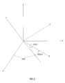
- FIG. 2illustrates one convention for defining orientation angles
- FIG. 3shows a minimal set of radiators for tracking a moving object with a single sensor
- FIG. 4shows another set of radiators for tracking a moving object with a single sensor
- FIG. 5shows a set of radiators for tracking a moving object that is equipped with both a single sensor and a set of three orthogonal sensors
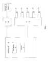
- FIGS. 6 and 11are schematic block diagrams of systems of the present invention.
- FIG. 7shows a preferred single sensor coil of the present invention and some of the associated electronics
- FIGS. 8A, 8 B, 9 and 10illustrate guide wires of the present invention.
- FIG. 1shows a moving object 10 provided with three orthogonal sensor coils 12 , 14 and 16 of electrically conducting wire, electrically coupled to reception circuitry 18 . Also provided are three independent transmitters of quasistatic electromagnetic radiation, each of which includes a respective spatially extended antenna 20 , 22 or 24 . By “independent” generators is meant that the field generated by one generator can not be expressed as a linear combination of the fields generated by the other two generators. Transmission circuitry 26 includes the remainder of the three transmitters, as well as circuitry for synchronizing the transmissions.
- Each antenna 20 , 22 or 24radiates a respective quasistatic electromagnetic field, the magnetic component of which excites a respective electrical current in each of sensor coils 12 , 14 and 16 . It is assumed that sensor coils 12 , 14 and 16 are sufficiently small that the gradient of the magnetic field at sensor coils 12 , 14 and 16 is spatially uniform. This magnetic field is referred to in the subsequent discussion as the magnetic field “at” object 10 .
- the vectorial magnetic field radiated by antenna 20as B I ( r ), the vectorial magnetic field radiated by antenna 22 as B 7 (r ), and the vectorial magnetic field radiated by antenna 24 as B 3 ( r ).
- These fieldsare functions of a position vector r whose Cartesian components (in the frame of reference defined by antennas 20 , 22 and 24 ) are (x,y,z).
- the corresponding Cartesian components of B 1are (B 1x ,B 1y ,B 1z ), and similarly for B 7 and B 3 .
- Define a 3 ⁇ 3 matrix Bwhose three columns are the vectorial magnetic fields B I , B 7 and B 3 .
- the signals received by reception circuitry 18can be represented as another 3 ⁇ 3 matrix S that is related to B by a 3 ⁇ 3 rotation matrix R and a scale factor k that is independent of position r :
- the rotation matrix Raccounts for sensor coils 12 , 14 and 16 in generally not being aligned with the Cartesian axis of the reference frame.
- Ris an identity matrix.
- vis obtained from S by left-multiplying S by the row vector (1,0,0).
- the matrix Bis non-singular.
- Right-multiplying v by B ⁇ 1 k ⁇ 1 and taking the magnitude of the resulting row vectorgives
- independent setsis meant that the magnetic field matrix B generated by one set can not be expressed as a linear combination of the magnetic field matrices B generated by the other two sets.
- An equation such as equation (1)can be defined for each of the three independent sets:
- equations (4)may be solved iteratively for the position of object 10 .
- B ⁇ 1 k ⁇ 1is as polynomials in x, y and z.
- the orientation of object 10may be determined.
- the elements of Rgenerally, and the three elements R 11 , R 12 and R 13 of the first row of R in particular, are trigonometric functions of the angles that define the orientation of object 18 . Equations (3) thus constitute three independent equations for these orientation angles.
- FIG. 2shows the local Cartesian coordinate axes (x',y',z') of object 10 rotated with respect to the Cartesian coordinate axes (x,y,z) of the frame of reference.
- YAWis the angle between the x-axis and the projection on the xy plane of the x' axis.
- PITCHis the angle between the xy plane and the x' axis.
- ROLLis the rotation of the y' and z' axes about the x' axis. Note that with only one sensor coil present in object 10 , only two of these angles can be determined, as can be seen by considering the case of sensor coil 12 directed along the x' axis: the signals received by reception circuitry 18 then are independent of ROLL.
- (R′ 11 ,R′ 12 ,R′ 13 )is the first row of a rotation matrix R′ that is related to R by the rotation that transforms the direction in which sensor coil 12 points into the direction in which sensor coil 14 points, so that R 11 , R 12 , R 13 , R′ 11 , R′ 12 and R′ 13 all are trigonometric functions of the same YAW, PITCH and ROLL of object 10 .
- R′ 11 ,R′ 12 ,R′ 13is the first row of a rotation matrix R′ that is related to R by the rotation that transforms the direction in which sensor coil 12 points into the direction in which sensor coil 14 points, so that R 11 , R 12 , R 13 , R′ 11 , R′ 12 and R′ 13 all are trigonometric functions of the same YAW, PITCH and ROLL of object 10 .
- the first of three equations for ris obtained by right-multiplying v 1 by B ⁇ 1 k ⁇ 1 as before and taking the magnitude of the
- the third equationis obtained from the dot product of (R 11 ,R 12 ,R 13 ) and (R′ 11 ,R′ 12 ,R′ 13 ):
- equations (6)as before for r gives the position of object 10 .
- equations (5 a ), (5 b ) and (6 c )provide three equations for the three orientation angles of object 10 . In this case, however, all three orientation angles may be found.
- Equation (4) or of equations (6) for the position of object 10presupposes the availability of B a , B b and B c , (in the case of one sensor coil on object 10 ), or the availability of B (in the case of two sensor coils on object 10 ) as algebraic functions of x, y and z. These algebraic functions are obtained in a calibration procedure discussed below.
- the present inventionis of a method and system for tracking a moving object. Specifically, the present invention can be used to determine the position of a moving object without having to determine the orientation of the object, and with the use of only one or two vector field sensors on the object.
- FIG. 3illustrates the minimal set of radiators needed to implement the present invention in the case of a single magnetic field component sensor on object 10 : five planar loop antennas 30 , 32 , 34 , 36 and 38 .
- antennas 30 , 32 , 34 , 36 and 38are nonoverlapping and coplanar.
- Object 10moves in the space 39 adjacent to antennas 30 , 32 , 34 , 36 and 38 , off to one side of the common plane of antennas 30 , 32 , 34 , 36 and 38 , so that antennas 30 , 32 , 34 , 36 and 38 all are spatially extended relative to object 10 .
- the first independent set (set a) of transmitting antennasconsists of antennas 30 , 34 and 36 .
- the second independent set (set b) of transmitting antennasconsists of antennas 32 , 36 and 38 .
- the third set (set c) of transmitting antennasconsists of antennas 34 , 36 and 38 .
- FIG. 4shows one preferred layout of transmitting antennas, in three sets of orthogonal coils.
- Set aincludes coils 40 , 40 ′ and 40 ′′.
- Set bincludes coils 42 , 42 ′ and 42 ′′.
- Set cincludes coils 44 , 44 ′ and 44 ′′.
- the method of the present inventionpresupposes the availability of algebraic expressions for the matrices B a , B b and B c as functions of position r .
- One way to obtain these algebraic expressionsis theoretical, as in the prior art of Acker (U.S. Pat. No. 5,729,129), Blood (U.S. Pat. No. 5,600,330) and Gilboa et al. (EP 922,966).
- spatially localized transmitting antennassuch as the transmitting antennas of FIG. 4 are modeled as point dipoles; and spatially extended transmitting antennas, such as the transmitting antennas of FIG.
- each component M of each inverse matrixis expressed as a parametrized function of position coordinates (x,y,z).
- Equations (4)then look like:
- Another way to obtain the inverse matricesis empirically.
- Object 10is moved successively among the N calibration points r n .
- object 10is pointed so that sensor 12 is oriented, first in the +x direction, then in the +y direction, and finally in the +z direction.
- the transmitters that contribute to B a , B b and B care excited successively. So, for example, with object 10 at position r and pointed so that sensor 12 is oriented in the +x direction, exciting the transmitter that generates the first column of B a produces a signal in reception circuitry 18 that is equal to the x-component of the first column of B a ( r ), multiplied by k. In this manner kB a , kB b and kB c are measured at all N calibration points r n , and then are inverted to give the inverse matrices.
- the empirical method of obtaining the inverse matricesis effected using a calibration object with all three orthogonal sensors 12 , 14 and 16 .
- the calibration objectis pointed so that sensor 12 is oriented in the +x direction, sensor 14 is oriented in the +y direction, and sensor 16 is oriented in the +z direction.
- the transmitters that contribute to B a , B b an B care excited successively.
- the antennas used to generate the magnetic fieldsare chosen to minimize the polynomial order that gives adequate numerical accuracy.
- the antennas taught by Gilboa in U.S. Pat. No. 5,853,327 and illustrated in FIG. 13 of that patentand the antennas taught by Gilboa et al. in WO 00/10456 (which is incorporated by reference for all purposes as if fully set forth herein) and illustrated in FIG. 6 of that PCT application, generate magnetic fields that can be represented by low order polynomials, as illustrated in FIG. 14 of U.S. Pat. No. 5,853,327.
- Another set of eight antennas 80 that minimize the polynomial orderis shown in FIG. 5 . With such antennas, polynomials of fifth order, with 56 coefficients C jkl each, are adequate. Note that the minimal radiator set illustrated in FIG. 3 is in fact antennas 80 a through 80 e.
- Antennas 80have the further advantage of allowing the convenient use of both a single magnetic field component sensor and a three-component sensor in object 10 .
- the antennas of FIG. 6 of that PCT applicationare energized to produce magnetic fields that are symmetric, antisymmetric horizontally as seen in FIG. 6 of that PCT application, or antisymmetric vertically as seen in FIG. 6 of that PCT application, or, most preferably, magnetic fields that can be combined linearly to produce total magnetic fields of such symmetries.
- running direct electrical current in all eight antennas 80 in a common (clockwise or anticlockwise) directionproduces a symmetric total DC magnetic field
- running electrical current in antennas 80 a , 80 d and 80 f in one direction and in antennas 80 c , 80 e and 80 h in the opposite directionproduces a total DC magnetic field that is horizontally antisymmetric as seen in FIG. 5
- running electrical current in antennas 80 a , 80 b and 80 c in one direction and in antennas 80 f , 80 g and 80 h in the opposite directionproduces a total DC magnetic field that is vertically antisymmetric as seen in FIG. 5 .
- running alternating electrical current in all eight antennas 80 with a common phaseproduces a symmetric total AC magnetic field
- running alternating electrical current in antennas 80 c , 80 e and 80 h with a phase opposite to the phase of alternating electrical current in antennas 80 a , 80 d and 80 fproduces a total AC magnetic field that is horizontally antisymmetric as seen in FIG. 5
- running alternating electrical current in antennas 80 f , 80 g and 80 h with a phase opposite to the phase of alternating electrical current in antennas 80 a , 80 b and 80 cproduces a total AC magnetic field that is vertically antisymmetric as seen in FIG. 5 .
- the antennas of FIG. 4may be used similarly in conjunction with an object 10 that bears both a single magnetic field component sensor and a three-component sensor.
- coils 40 , 40 ′, 40 ′′, 42 , 42 ′, 42 ′′, 44 , 44 ′and 44 ′′used successively as transmitters, let the total field magnitudes measured by the three-component sensor at any particular position of object 10 be M 40 , M 40′ , M 40′′ , M 42, M 42′ , M 42′′ , M 44 , M 44 ′ and M 44 ′′ , respectively.
- L 40log(M 40 +M 40′ +M 40′′ )
- L 42log(M 42 +M 42′ +M 42′′ )
- L 44log(M 44 +M 44′ +M 44′′ ).
- the orientation of object 10is obtained from the single-component sensor measurements as described above.
- equations (4)or of equations (8) that relate the signals received by reception circuitry 18 from sensor 12 to the position r of object 10 .
- equations (3)are solved by standard methods for solving nonlinear equations. See, for example, William H. Press et al., Numerical Recipes in C (Cambridge, 1992), chapter 9. With the position r of object 10 determined, equations (3) become three simultaneous linear equations for R 11 , R 12 and R 13 ; and the YAW and PITCH of object 10 are simple inverse trigonometric functions of R 11 , R 12 and R 13 .
- Equations (6)are solved for the position r of object 10 . If desired, equations (5 a ), (5 b ) and (6 c ) are solved for all three orientation angles (YAW, PITCH and ROLL) of object 10 .
- the scope of the present inventionalso includes the use of three or more sensors on object 10 .
- the prior artdoes not teach the use of empirically determined parameters in equations such as equations (4) for locating a moving object, even when three or more sensors are used.
- FIG. 6is a schematic block diagram of a system of the present invention for tracking moving object 10 using a single vector field sensor 52 that supplies signals to reception circuitry 58 .
- vector field sensor 52may be a coil of electrically conductive wire, in the manner of sensors 12 , 14 and 16 , for sensing quasistatic magnetic fields, or one of the single component magnetometers listed above, for sensing static magnetic fields.
- the vector fieldsare generated using five vector field radiators 62 , 64 , 66 , 68 and 70 .
- Antennas 30 , 32 , 34 , 36 and 38are examples of vector field radiators 62 , 64 , 66 , 68 and 70 in the case of the vector fields being static or quasistatic magnetic fields.
- Radiomodulators 62 , 64 , 66 , 68 and 70are excited using transmission circuitry 60 .
- Transmission circuitry 60 and reception circuitry 58are under the overall control of a control unit 76 that includes a memory 74 for storing coefficients C jkl and a processor 72 for solving equations (4).
- FIG. 7shows a preferred configuration of a sensor coil 12 mounted within an elongated object 10 that has an electrically conducting outer housing 110 , and that is configured to suppress electromagnetic coupling.
- sensor coil 12has two subcoils, 12 a and 12 b , connected in series by inner leads 112 a and 112 b thereof.
- An outer lead 212 a of subcoil 12 ais connected by a wire 82 a of a twisted wire pair 82 to a positive input 84 a of a differential amplifier 86 of reception circuitry 58 .
- An outer lead 212 b of subcoil 12 bis connected by a wire 82 b of twisted wire pair 82 to a negative input 84 b of differential amplifier 86 .
- Inner leads 112 a and 112 balso are grounded to outer housing 110 , as shown.
- the sensor coil or coils of the present inventionare integrated into a guide wire such as is used to aid in the insertion of a catheter into the body of a medical or veterinary patient and to evaluate the body cavity (for example a blood vessel) through which the catheter will travel.
- a guide wireis inserted into a body system such as a blood vessel and the vessel is probed with the guide wire. The catheter is slipped over the guide wire and the guide wire is withdrawn. The catheter is then eased through the vessel to the desired location.
- FIGS. 8A and 8Billustrate one such guide wire 300 of the present invention.
- FIG. 8Ais an external view of guide wire 300 .
- FIG. 8Bis a cut away view of guide wire 300 .
- Guide wire 300consists of a helical coil 302 that is wound about a longitudinal axis 314 of a central channel 312 and that is capped on the distal end thereof by a hemispherical cap 304 .
- Coil 302includes a distal portion 306 , a medial portion 308 and a proximal portion 310 .
- Portions 306 , 308 and 310are in tandem, meaning that these portions are situated successively along axis 314 .
- Ellipses. . .
- Distal portion 306 and proximal portion 310are made of an electrically conducting material, preferably a metal such as copper, silver, gold, platinum, palladium or the like, most preferably copper.
- the electrically conducting portions of helical coil 302i.e., distal portion 306 and proximal portion 310 preferably are coated with an electrical insulator, such as a thin layer of polyurethane.
- Medial portion 308is made of an electrical insulator, as indicated by the shading of medial portion 308 .
- Distal portion 306constitutes a sensor coil for sensing a magnetic field component of a quasistatic electromagnetic field.
- a first electrically conducting wire 316is electrically coupled, for example by soldering, to a distal end 320 of distal portion 306 .
- Wire 316runs, substantially parallel to axis 314 , towards the proximal end of guide wire 300 .
- a second electrically conducting wire 318is electrically coupled, for example by soldering, to a proximal end 322 of distal portion 306 .
- Wire 318runs, substantially parallel to axis 314 , towards the proximal end of guide wire 300 .
- wires 316 and 318form a twisted pair.
- wires 316 and 318lead to reception circuitry such as reception circuitry 58 .
- FIG. 9illustrates another such guide wire 400 of the present invention.
- Guide wire 400consists of a helical coil 402 that is capped on the distal end thereof by a hemispherical cap 404 .
- guide wire 400includes a distal portion 406 , a medial portion 408 and a proximal portion 410 , all in tandem. The ellipsis indicates that proximal portion 410 continues to the left.
- proximal portion 310 of guide wire 300proximal portion 410 of guide wire 400 is made of an electrically conducting material.
- medial portion 408 of guide wire 400is made of an electrical insulator.
- distal portion 406 of guide wire 400includes three sections in tandem: an electrically conducting distal section 424 , an electrically insulating medial section 426 and an electrically conducting proximal section 428 .
- Electrically conducting section 424 and 428constitute sensor coils for sensing respective magnetic field components of a quasistatic electromagnetic field.
- electrically conducting sections 424 and 428are connected to reception circuitry such as reception circuitry 58 by respective twisted wire pairs.
- distal portion 406is sufficiently long to be significantly flexible, and if medial section 426 is relatively long compared to distal section 424 and proximal section 428 , then the measured positions and orientations of distal section 424 and proximal section 428 indicate both the location of distal portion 406 and the extent to which distal portion 406 is bent. If distal portion 406 is relatively short, so that distal section 424 and proximal section 428 always are nearly aligned with each other, then distal section 424 and proximal section 428 preferably are connected as illustrated in FIG. 7 to provide a single sensor coil. Because of the inherent flexibility of coil 402 , distal section 424 and proximal section 428 in general are not exactly aligned with each other. Consequently, the orientation that is measured using distal section 424 and proximal section 428 in the configuration of FIG. 7 is an average orientation of distal portion 406 .
- FIG. 10illustrates, schematically, a guide wire 400 of the present invention, the distal portion whereof is equipped with two sensor coils 404 and 406 .
- Sensor coil 404at the distal tip of guide wire 400 , is substantially parallel to longitudinal axis 402 of guide wire 400 .
- Sensor coil 406is positioned proximal of sensor coil 404 and is substantially perpendicular to axis 402 .
- the present inventionmeasures the position ( r 2 ) of the center of coil 404 , as well as a unit vector û 1 that points in the direction of the axis of coil 404 .
- the present inventionalso measures the position ( r 2 ) of the center of coil 406 , as well as a unit vector û 2 that points in the direction of the axis of coil 406 . Assuming that the distal portion of guide wire 400 is bent in a circle, this circle is fully determined by position vectors r 1 and r 2 and by unit vector û 1 . Note that unit vector û 1 is tangent to the circle. Unit vector û 2 then determines the degree to which guide wire 400 is twisted.
- FIG. 11is a schematic block diagram of a system of the present invention for tracking moving object 10 using two vector field sensors 52 and 54 .
- the system of FIG. 11is almost identical to the system of FIG. 6, the two main differences being that the system of FIG. 11 includes two vector field sensors 52 and 54 but only three vector field radiators 62 , 64 and 66 .
Landscapes
- Life Sciences & Earth Sciences (AREA)
- Health & Medical Sciences (AREA)
- Engineering & Computer Science (AREA)
- Physics & Mathematics (AREA)
- Heart & Thoracic Surgery (AREA)
- Surgery (AREA)
- Pathology (AREA)
- Biomedical Technology (AREA)
- Human Computer Interaction (AREA)
- Medical Informatics (AREA)
- Molecular Biology (AREA)
- Biophysics (AREA)
- Animal Behavior & Ethology (AREA)
- General Health & Medical Sciences (AREA)
- Public Health (AREA)
- Veterinary Medicine (AREA)
- General Physics & Mathematics (AREA)
- Measurement Of Length, Angles, Or The Like Using Electric Or Magnetic Means (AREA)
Abstract
Description


Claims (64)
Priority Applications (1)
| Application Number | Priority Date | Filing Date | Title |
|---|---|---|---|
| US09/819,676US6615155B2 (en) | 2000-03-09 | 2001-03-29 | Object tracking using a single sensor or a pair of sensors |
Applications Claiming Priority (4)
| Application Number | Priority Date | Filing Date | Title |
|---|---|---|---|
| US18802500P | 2000-03-09 | 2000-03-09 | |
| IL10022401 | 2001-03-09 | ||
| IL01/00224 | 2001-03-09 | ||
| US09/819,676US6615155B2 (en) | 2000-03-09 | 2001-03-29 | Object tracking using a single sensor or a pair of sensors |
Publications (2)
| Publication Number | Publication Date |
|---|---|
| US20020062203A1 US20020062203A1 (en) | 2002-05-23 |
| US6615155B2true US6615155B2 (en) | 2003-09-02 |
Family
ID=27271527
Family Applications (1)
| Application Number | Title | Priority Date | Filing Date |
|---|---|---|---|
| US09/819,676Expired - LifetimeUS6615155B2 (en) | 2000-03-09 | 2001-03-29 | Object tracking using a single sensor or a pair of sensors |
Country Status (1)
| Country | Link |
|---|---|
| US (1) | US6615155B2 (en) |
Cited By (150)
| Publication number | Priority date | Publication date | Assignee | Title |
|---|---|---|---|---|
| US20030184285A1 (en)* | 2002-03-27 | 2003-10-02 | Visualization Technology | Magnetic tracking system |
| US20040181360A1 (en)* | 2002-12-18 | 2004-09-16 | Masamitsu Fukushima | Three-dimensional information detecting system, three-dimensional information detecting device and input device for three-dimensional information detecting system |
| US20050062469A1 (en)* | 2003-09-23 | 2005-03-24 | Anderson Peter Traneus | System and method for hemisphere disambiguation in electromagnetic tracking systems |
| US6876325B1 (en) | 2004-04-01 | 2005-04-05 | Itt Manufacturing Enterprises, Inc. | System and method for location-finding using communication signals |
| US20050077085A1 (en)* | 2003-10-14 | 2005-04-14 | Rudolf Zeller | Tracking positions of personnel, vehicles, and inanimate objects |
| US20050103333A1 (en)* | 2000-12-02 | 2005-05-19 | Bonutti Peter M. | Medical device positioning system and method |
| US20050222554A1 (en)* | 2004-03-05 | 2005-10-06 | Wallace Daniel T | Robotic catheter system |
| US20050225320A1 (en)* | 2004-04-09 | 2005-10-13 | Lee Joong K | Inductive position sensor |
| US20050223841A1 (en)* | 2004-04-09 | 2005-10-13 | Lee Joong K | Inductive sensor for vehicle electronic throttle control |
| US20060241396A1 (en)* | 2005-02-10 | 2006-10-26 | Fabian Carl E | Multi-modal detection of surgical sponges and implements |
| US20060247683A1 (en)* | 2005-04-21 | 2006-11-02 | Asthmatx, Inc. | Control systems for delivering energy |
| US20060250305A1 (en)* | 2004-04-01 | 2006-11-09 | Itt Manufacturing Enterprises, Inc. | Method and system for determining the position of an object |
| US20060255794A1 (en)* | 2005-04-08 | 2006-11-16 | Lee Joong K | Signal conditioning system for inductive position sensor |
| US20070001666A1 (en)* | 2005-06-27 | 2007-01-04 | Lee Joong K | Linear and rotational inductive position sensor |
| US7272495B2 (en) | 2004-04-01 | 2007-09-18 | Itt Manufacturing Enterprises, Inc. | System and method for inverse multilateration |
| US20070265526A1 (en)* | 2006-05-11 | 2007-11-15 | Assaf Govari | Low-profile location pad |
| US20080009760A1 (en)* | 2006-06-30 | 2008-01-10 | Broncus Technologies, Inc. | Airway bypass site selection and treatment planning |
| US20080054887A1 (en)* | 2004-04-09 | 2008-03-06 | Lee Joong K | Inductive position sensor |
| US20080255446A1 (en)* | 2007-04-16 | 2008-10-16 | General Electric Company | System and method of integrating electromagnetic microsensors in guidewires |
| US20080287860A1 (en)* | 2007-05-16 | 2008-11-20 | General Electric Company | Surgical navigation system with a trackable ultrasound catheter |
| US20090038850A1 (en)* | 2007-08-07 | 2009-02-12 | Brune Guenter W | Advanced Steering Tool System, Method and Apparatus |
| US20090118620A1 (en)* | 2007-11-06 | 2009-05-07 | General Electric Company | System and method for tracking an ultrasound catheter |
| US20090131784A1 (en)* | 2005-12-29 | 2009-05-21 | Ido Betesh | System and method of in-vivo magnetic position determination |
| WO2009074872A2 (en) | 2007-07-09 | 2009-06-18 | Superdimension, Ltd. | Patent breathing modeling |
| US20090227861A1 (en)* | 2008-03-06 | 2009-09-10 | Vida Diagnostics, Inc. | Systems and methods for navigation within a branched structure of a body |
| WO2009147671A1 (en) | 2008-06-03 | 2009-12-10 | Superdimension Ltd. | Feature-based registration method |
| US20090326368A1 (en)* | 2008-06-30 | 2009-12-31 | General Electric Company | System and Method For Integrating Electromagnetic Microsensors in Guidewires |
| US20100008555A1 (en)* | 2008-05-15 | 2010-01-14 | Superdimension, Ltd. | Automatic Pathway And Waypoint Generation And Navigation Method |
| US20100034449A1 (en)* | 2008-06-06 | 2010-02-11 | Superdimension, Ltd. | Hybrid Registration Method |
| US7722565B2 (en) | 2004-11-05 | 2010-05-25 | Traxtal, Inc. | Access system |
| WO2010071895A1 (en) | 2008-12-19 | 2010-06-24 | Superdimension, Ltd. | Navigable tissue treatment tools |
| US7751868B2 (en) | 2004-11-12 | 2010-07-06 | Philips Electronics Ltd | Integrated skin-mounted multifunction device for use in image-guided surgery |
| US7805269B2 (en) | 2004-11-12 | 2010-09-28 | Philips Electronics Ltd | Device and method for ensuring the accuracy of a tracking device in a volume |
| EP2238901A2 (en) | 2009-04-08 | 2010-10-13 | Superdimension, LTD. | Locatable catheter |
| US7840254B2 (en) | 2005-01-18 | 2010-11-23 | Philips Electronics Ltd | Electromagnetically tracked K-wire device |
| EP2253287A2 (en) | 2009-05-14 | 2010-11-24 | superDimension Ltd. | Automatic registration technique |
| US7976539B2 (en) | 2004-03-05 | 2011-07-12 | Hansen Medical, Inc. | System and method for denaturing and fixing collagenous tissue |
| US20110174539A1 (en)* | 2010-01-19 | 2011-07-21 | Brune Guenter W | Advanced Underground Homing System, Apparatus and Method |
| US20110206253A1 (en)* | 2010-02-01 | 2011-08-25 | Superdimension, Ltd. | Region-Growing Algorithm |
| US20110270081A1 (en)* | 2010-04-30 | 2011-11-03 | Medtronic Xomed, Inc. | Navigated Malleable Surgical Instrument |
| US20110319751A1 (en)* | 2007-05-31 | 2011-12-29 | General Electric Company | Dynamic reference method and system for use with surgical procedures |
| EP2401956A1 (en) | 2008-07-10 | 2012-01-04 | Superdimension Ltd. | Integrated multi-functional endoscopic tool |
| US8098240B2 (en) | 2008-06-20 | 2012-01-17 | Mattel, Inc. | Capacitive touchpad and toy incorporating the same |
| US20120041453A1 (en)* | 2010-08-13 | 2012-02-16 | Klaus Klingenbeck | Fastening Device for a Mitral Valve and Method |
| US8333204B2 (en) | 1999-06-25 | 2012-12-18 | Hansen Medical, Inc. | Apparatus and methods for treating tissue |
| US8380289B2 (en) | 2010-11-18 | 2013-02-19 | Robert D. Zellers | Medical device location systems, devices and methods |
| US8391956B2 (en) | 2010-11-18 | 2013-03-05 | Robert D. Zellers | Medical device location systems, devices and methods |
| US8388541B2 (en) | 2007-11-26 | 2013-03-05 | C. R. Bard, Inc. | Integrated system for intravascular placement of a catheter |
| US8388546B2 (en) | 2006-10-23 | 2013-03-05 | Bard Access Systems, Inc. | Method of locating the tip of a central venous catheter |
| US8437833B2 (en) | 2008-10-07 | 2013-05-07 | Bard Access Systems, Inc. | Percutaneous magnetic gastrostomy |
| US8478382B2 (en) | 2008-02-11 | 2013-07-02 | C. R. Bard, Inc. | Systems and methods for positioning a catheter |
| US8512256B2 (en) | 2006-10-23 | 2013-08-20 | Bard Access Systems, Inc. | Method of locating the tip of a central venous catheter |
| US8611983B2 (en) | 2005-01-18 | 2013-12-17 | Philips Electronics Ltd | Method and apparatus for guiding an instrument to a target in the lung |
| US8608724B2 (en) | 2004-07-19 | 2013-12-17 | Broncus Medical Inc. | Devices for delivering substances through an extra-anatomic opening created in an airway |
| US8632461B2 (en) | 2005-06-21 | 2014-01-21 | Koninklijke Philips N.V. | System, method and apparatus for navigated therapy and diagnosis |
| USD699359S1 (en) | 2011-08-09 | 2014-02-11 | C. R. Bard, Inc. | Ultrasound probe head |
| US8709034B2 (en) | 2011-05-13 | 2014-04-29 | Broncus Medical Inc. | Methods and devices for diagnosing, monitoring, or treating medical conditions through an opening through an airway wall |
| US8781555B2 (en) | 2007-11-26 | 2014-07-15 | C. R. Bard, Inc. | System for placement of a catheter including a signal-generating stylet |
| US8784336B2 (en) | 2005-08-24 | 2014-07-22 | C. R. Bard, Inc. | Stylet apparatuses and methods of manufacture |
| US8801693B2 (en) | 2010-10-29 | 2014-08-12 | C. R. Bard, Inc. | Bioimpedance-assisted placement of a medical device |
| US8849382B2 (en) | 2007-11-26 | 2014-09-30 | C. R. Bard, Inc. | Apparatus and display methods relating to intravascular placement of a catheter |
| USD724745S1 (en) | 2011-08-09 | 2015-03-17 | C. R. Bard, Inc. | Cap for an ultrasound probe |
| US9125578B2 (en) | 2009-06-12 | 2015-09-08 | Bard Access Systems, Inc. | Apparatus and method for catheter navigation and tip location |
| US9138165B2 (en) | 2012-02-22 | 2015-09-22 | Veran Medical Technologies, Inc. | Systems, methods and devices for forming respiratory-gated point cloud for four dimensional soft tissue navigation |
| US9211107B2 (en) | 2011-11-07 | 2015-12-15 | C. R. Bard, Inc. | Ruggedized ultrasound hydrogel insert |
| US9218664B2 (en) | 2005-09-13 | 2015-12-22 | Veran Medical Technologies, Inc. | Apparatus and method for image guided accuracy verification |
| US9226689B2 (en) | 2009-03-10 | 2016-01-05 | Medtronic Xomed, Inc. | Flexible circuit sheet |
| US9226688B2 (en) | 2009-03-10 | 2016-01-05 | Medtronic Xomed, Inc. | Flexible circuit assemblies |
| US9232985B2 (en) | 2009-03-10 | 2016-01-12 | Medtronic Xomed, Inc. | Navigating a surgical instrument |
| US9339206B2 (en) | 2009-06-12 | 2016-05-17 | Bard Access Systems, Inc. | Adaptor for endovascular electrocardiography |
| US9345532B2 (en) | 2011-05-13 | 2016-05-24 | Broncus Medical Inc. | Methods and devices for ablation of tissue |
| US9358076B2 (en) | 2011-01-20 | 2016-06-07 | Hansen Medical, Inc. | System and method for endoluminal and translumenal therapy |
| US9398892B2 (en) | 2005-06-21 | 2016-07-26 | Koninklijke Philips N.V. | Device and method for a trackable ultrasound |
| US9408669B2 (en) | 2013-03-15 | 2016-08-09 | Hansen Medical, Inc. | Active drive mechanism with finite range of motion |
| WO2016134282A1 (en)* | 2015-02-20 | 2016-08-25 | Nostix, Llc | Medical device position location systems, devices and methods |
| WO2016134297A1 (en)* | 2015-02-20 | 2016-08-25 | Nostix, Llc | Medical device position location systems, devices and methods |
| US9427172B2 (en) | 2011-12-30 | 2016-08-30 | Mediguide Ltd. | Roll detection and six degrees of freedom sensor assembly |
| US9445734B2 (en) | 2009-06-12 | 2016-09-20 | Bard Access Systems, Inc. | Devices and methods for endovascular electrography |
| US9457168B2 (en) | 2005-07-01 | 2016-10-04 | Hansen Medical, Inc. | Robotic catheter system and methods |
| US9456766B2 (en) | 2007-11-26 | 2016-10-04 | C. R. Bard, Inc. | Apparatus for use with needle insertion guidance system |
| US9492097B2 (en) | 2007-11-26 | 2016-11-15 | C. R. Bard, Inc. | Needle length determination and calibration for insertion guidance system |
| US9521961B2 (en) | 2007-11-26 | 2016-12-20 | C. R. Bard, Inc. | Systems and methods for guiding a medical instrument |
| US9532724B2 (en) | 2009-06-12 | 2017-01-03 | Bard Access Systems, Inc. | Apparatus and method for catheter navigation using endovascular energy mapping |
| US9533128B2 (en) | 2003-07-18 | 2017-01-03 | Broncus Medical Inc. | Devices for maintaining patency of surgically created channels in tissue |
| US20170016965A1 (en)* | 2015-07-17 | 2017-01-19 | Allegro Microsystems, Llc | Methods and Apparatus For Trimming A Magnetic Field Sensor |
| US9554716B2 (en) | 2007-11-26 | 2017-01-31 | C. R. Bard, Inc. | Insertion guidance system for needles and medical components |
| US9575140B2 (en) | 2008-04-03 | 2017-02-21 | Covidien Lp | Magnetic interference detection system and method |
| US9636031B2 (en) | 2007-11-26 | 2017-05-02 | C.R. Bard, Inc. | Stylets for use with apparatus for intravascular placement of a catheter |
| US9649048B2 (en) | 2007-11-26 | 2017-05-16 | C. R. Bard, Inc. | Systems and methods for breaching a sterile field for intravascular placement of a catheter |
| US9661991B2 (en) | 2005-08-24 | 2017-05-30 | Koninklijke Philips N.V. | System, method and devices for navigated flexible endoscopy |
| US9750486B2 (en) | 2011-10-25 | 2017-09-05 | Medtronic Navigation, Inc. | Trackable biopsy needle |
| US9839372B2 (en) | 2014-02-06 | 2017-12-12 | C. R. Bard, Inc. | Systems and methods for guidance and placement of an intravascular device |
| EP3260042A1 (en) | 2006-11-10 | 2017-12-27 | Covidien LP | Adaptive navigation technique for navigating a catheter through a body channel or cavity |
| US9901714B2 (en) | 2008-08-22 | 2018-02-27 | C. R. Bard, Inc. | Catheter assembly including ECG sensor and magnetic assemblies |
| US9974501B2 (en) | 2011-01-28 | 2018-05-22 | Medtronic Navigation, Inc. | Method and apparatus for image-based navigation |
| US20180164387A1 (en)* | 2016-12-13 | 2018-06-14 | Infineon Technologies Ag | Magnetic sensor circuits and systems and methods for forming magnetic sensor circuits |
| US10046139B2 (en) | 2010-08-20 | 2018-08-14 | C. R. Bard, Inc. | Reconfirmation of ECG-assisted catheter tip placement |
| US10046140B2 (en) | 2014-04-21 | 2018-08-14 | Hansen Medical, Inc. | Devices, systems, and methods for controlling active drive systems |
| US10098567B2 (en) | 2015-04-29 | 2018-10-16 | Teleflex Medical Devices S.À R.L | Medical device position location systems, devices and methods |
| US10188831B2 (en) | 2013-03-14 | 2019-01-29 | Angiodynamics, Inc. | Systems and methods for catheter tip placement using ECG |
| US10264947B2 (en) | 2010-08-20 | 2019-04-23 | Veran Medical Technologies, Inc. | Apparatus and method for airway registration and navigation |
| US10272260B2 (en) | 2011-11-23 | 2019-04-30 | Broncus Medical Inc. | Methods and devices for diagnosing, monitoring, or treating medical conditions through an opening through an airway wall |
| US10278729B2 (en) | 2013-04-26 | 2019-05-07 | Medtronic Xomed, Inc. | Medical device and its construction |
| US10349890B2 (en) | 2015-06-26 | 2019-07-16 | C. R. Bard, Inc. | Connector interface for ECG-based catheter positioning system |
| US10363103B2 (en) | 2009-04-29 | 2019-07-30 | Auris Health, Inc. | Flexible and steerable elongate instruments with shape control and support elements |
| US10418705B2 (en) | 2016-10-28 | 2019-09-17 | Covidien Lp | Electromagnetic navigation antenna assembly and electromagnetic navigation system including the same |
| US10413272B2 (en) | 2016-03-08 | 2019-09-17 | Covidien Lp | Surgical tool with flex circuit ultrasound sensor |
| US10426555B2 (en) | 2015-06-03 | 2019-10-01 | Covidien Lp | Medical instrument with sensor for use in a system and method for electromagnetic navigation |
| US10446931B2 (en) | 2016-10-28 | 2019-10-15 | Covidien Lp | Electromagnetic navigation antenna assembly and electromagnetic navigation system including the same |
| US10449330B2 (en) | 2007-11-26 | 2019-10-22 | C. R. Bard, Inc. | Magnetic element-equipped needle assemblies |
| US10463439B2 (en) | 2016-08-26 | 2019-11-05 | Auris Health, Inc. | Steerable catheter with shaft load distributions |
| US10492868B2 (en) | 2011-01-28 | 2019-12-03 | Medtronic Navigation, Inc. | Method and apparatus for image-based navigation |
| EP3582376A1 (en) | 2018-06-13 | 2019-12-18 | Robert Bosch GmbH | Conveyor device with safety feature |
| EP3582386A1 (en) | 2018-06-13 | 2019-12-18 | Robert Bosch GmbH | Movement device with decoupled position regulators |
| DE102018209403A1 (en) | 2018-06-13 | 2019-12-19 | Robert Bosch Gmbh | Movement device composed of sub-assemblies |
| US10517505B2 (en) | 2016-10-28 | 2019-12-31 | Covidien Lp | Systems, methods, and computer-readable media for optimizing an electromagnetic navigation system |
| US10524691B2 (en) | 2007-11-26 | 2020-01-07 | C. R. Bard, Inc. | Needle assembly including an aligned magnetic element |
| US10524867B2 (en) | 2013-03-15 | 2020-01-07 | Auris Health, Inc. | Active drive mechanism for simultaneous rotation and translation |
| US10556092B2 (en) | 2013-03-14 | 2020-02-11 | Auris Health, Inc. | Active drives for robotic catheter manipulators |
| US10582879B2 (en) | 2004-02-17 | 2020-03-10 | Philips Electronics Ltd | Method and apparatus for registration, verification and referencing of internal organs |
| US10583271B2 (en) | 2012-11-28 | 2020-03-10 | Auris Health, Inc. | Method of anchoring pullwire directly articulatable region in catheter |
| US10615500B2 (en) | 2016-10-28 | 2020-04-07 | Covidien Lp | System and method for designing electromagnetic navigation antenna assemblies |
| US10617324B2 (en) | 2014-04-23 | 2020-04-14 | Veran Medical Technologies, Inc | Apparatuses and methods for endobronchial navigation to and confirmation of the location of a target tissue and percutaneous interception of the target tissue |
| US10617374B2 (en) | 2011-01-28 | 2020-04-14 | Medtronic Navigation, Inc. | Method and apparatus for image-based navigation |
| US10624701B2 (en) | 2014-04-23 | 2020-04-21 | Veran Medical Technologies, Inc. | Apparatuses and methods for registering a real-time image feed from an imaging device to a steerable catheter |
| DE102018218666A1 (en) | 2018-10-31 | 2020-04-30 | Robert Bosch Gmbh | Movement device with positioning system |
| US10638952B2 (en) | 2016-10-28 | 2020-05-05 | Covidien Lp | Methods, systems, and computer-readable media for calibrating an electromagnetic navigation system |
| US10639008B2 (en) | 2009-10-08 | 2020-05-05 | C. R. Bard, Inc. | Support and cover structures for an ultrasound probe head |
| US10667720B2 (en) | 2011-07-29 | 2020-06-02 | Auris Health, Inc. | Apparatus and methods for fiber integration and registration |
| US10687903B2 (en) | 2013-03-14 | 2020-06-23 | Auris Health, Inc. | Active drive for robotic catheter manipulators |
| US10722311B2 (en) | 2016-10-28 | 2020-07-28 | Covidien Lp | System and method for identifying a location and/or an orientation of an electromagnetic sensor based on a map |
| US10751126B2 (en) | 2016-10-28 | 2020-08-25 | Covidien Lp | System and method for generating a map for electromagnetic navigation |
| US10751509B2 (en) | 2007-11-26 | 2020-08-25 | C. R. Bard, Inc. | Iconic representations for guidance of an indwelling medical device |
| US10792106B2 (en) | 2016-10-28 | 2020-10-06 | Covidien Lp | System for calibrating an electromagnetic navigation system |
| US10820885B2 (en) | 2012-06-15 | 2020-11-03 | C. R. Bard, Inc. | Apparatus and methods for detection of a removable cap on an ultrasound probe |
| US10869650B2 (en) | 2014-11-06 | 2020-12-22 | Covidien Lp | System for tracking and imaging a treatment probe |
| US10874327B2 (en) | 2017-05-19 | 2020-12-29 | Covidien Lp | Systems and methods for tracking and imaging a treatment probe having an integrated sensor |
| US10973584B2 (en) | 2015-01-19 | 2021-04-13 | Bard Access Systems, Inc. | Device and method for vascular access |
| US10992079B2 (en) | 2018-10-16 | 2021-04-27 | Bard Access Systems, Inc. | Safety-equipped connection systems and methods thereof for establishing electrical connections |
| US11000207B2 (en) | 2016-01-29 | 2021-05-11 | C. R. Bard, Inc. | Multiple coil system for tracking a medical device |
| US11103213B2 (en) | 2009-10-08 | 2021-08-31 | C. R. Bard, Inc. | Spacers for use with an ultrasound probe |
| US11176666B2 (en) | 2018-11-09 | 2021-11-16 | Vida Diagnostics, Inc. | Cut-surface display of tubular structures |
| US11241559B2 (en) | 2016-08-29 | 2022-02-08 | Auris Health, Inc. | Active drive for guidewire manipulation |
| US11304629B2 (en) | 2005-09-13 | 2022-04-19 | Veran Medical Technologies, Inc. | Apparatus and method for image guided accuracy verification |
| US11607150B2 (en) | 2014-04-08 | 2023-03-21 | Angiodynamics Va Llc | Medical device placement system and a method for its use |
| US11744647B2 (en) | 2017-11-08 | 2023-09-05 | Teleflex Medical Incorporated | Wireless medical device navigation systems and methods |
| US11875459B2 (en) | 2020-04-07 | 2024-01-16 | Vida Diagnostics, Inc. | Subject specific coordinatization and virtual navigation systems and methods |
| US12089902B2 (en) | 2019-07-30 | 2024-09-17 | Coviden Lp | Cone beam and 3D fluoroscope lung navigation |
| US12266111B2 (en) | 2020-11-27 | 2025-04-01 | Vida Diagnostics, Inc. | Visualization of sub-pleural regions |
| US12440238B2 (en) | 2021-09-09 | 2025-10-14 | C. R. Bard, Inc. | Apparatus for use with needle insertion guidance system |
Families Citing this family (10)
| Publication number | Priority date | Publication date | Assignee | Title |
|---|---|---|---|---|
| US6834251B1 (en)* | 2001-12-06 | 2004-12-21 | Richard Fletcher | Methods and devices for identifying, sensing and tracking objects over a surface |
| US20160161241A1 (en)* | 2014-12-03 | 2016-06-09 | Honeywell International Inc. | Motion tracking system using one or more magnetic fields |
| US10478254B2 (en) | 2016-05-16 | 2019-11-19 | Covidien Lp | System and method to access lung tissue |
| JP6931393B2 (en)* | 2016-11-21 | 2021-09-01 | セント・ジュード・メディカル・インターナショナル・ホールディング・エスエーアールエルSt. Jude Medical International Holding S.a,r.l. | Perspective transparent magnetic field generator |
| FR3069068B1 (en)* | 2017-07-17 | 2019-08-23 | Sysnav | METHOD FOR LOCATING A EVOLVING OBJECT IN A MAGNETIC FIELD GENERATED BY A SET OF AT LEAST THREE MAGNETIC GENERATORS |
| US11219489B2 (en) | 2017-10-31 | 2022-01-11 | Covidien Lp | Devices and systems for providing sensors in parallel with medical tools |
| US20220151711A1 (en)* | 2019-07-31 | 2022-05-19 | Orsus, Llc | Devices And Methods For Guide Wire Placement |
| US11759150B2 (en)* | 2019-08-27 | 2023-09-19 | Biosense Webster (Israel) Ltd. | Accurate basket catheter tracking |
| WO2021226492A1 (en)* | 2020-05-07 | 2021-11-11 | Cascodium Llc | Devices, systems and methods using a common frame of reference to provide a consistent magnetic field orientation for magnetic coupling |
| DE102020207428A1 (en) | 2020-06-16 | 2021-12-16 | Robert Bosch Gesellschaft mit beschränkter Haftung | Method for calibrating a sensor model for determining a pose with a neural network as a pose determination model |
Citations (25)
| Publication number | Priority date | Publication date | Assignee | Title |
|---|---|---|---|---|
| US3868565A (en) | 1973-07-30 | 1975-02-25 | Jack Kuipers | Object tracking and orientation determination means, system and process |
| US3983474A (en) | 1975-02-21 | 1976-09-28 | Polhemus Navigation Sciences, Inc. | Tracking and determining orientation of object using coordinate transformation means, system and process |
| US4017858A (en) | 1973-07-30 | 1977-04-12 | Polhemus Navigation Sciences, Inc. | Apparatus for generating a nutating electromagnetic field |
| US4054881A (en) | 1976-04-26 | 1977-10-18 | The Austin Company | Remote object position locater |
| US4287809A (en) | 1979-08-20 | 1981-09-08 | Honeywell Inc. | Helmet-mounted sighting system |
| US4314251A (en) | 1979-07-30 | 1982-02-02 | The Austin Company | Remote object position and orientation locater |
| US4328548A (en) | 1980-04-04 | 1982-05-04 | The Austin Company | Locator for source of electromagnetic radiation having unknown structure or orientation |
| US4346384A (en) | 1980-06-30 | 1982-08-24 | The Austin Company | Remote object position and orientation locator |
| US4394831A (en) | 1981-02-12 | 1983-07-26 | Honeywell Inc. | Helmet metal mass compensation for helmet-mounted sighting system |
| US4396885A (en) | 1979-06-06 | 1983-08-02 | Thomson-Csf | Device applicable to direction finding for measuring the relative orientation of two bodies |
| US4613866A (en) | 1983-05-13 | 1986-09-23 | Mcdonnell Douglas Corporation | Three dimensional digitizer with electromagnetic coupling |
| US4710708A (en) | 1981-04-27 | 1987-12-01 | Develco | Method and apparatus employing received independent magnetic field components of a transmitted alternating magnetic field for determining location |
| US4737794A (en) | 1985-12-09 | 1988-04-12 | Mcdonnell Douglas Corporation | Method and apparatus for determining remote object orientation and position |
| US4742356A (en) | 1985-12-09 | 1988-05-03 | Mcdonnell Douglas Corporation | Method and apparatus for determining remote object orientation and position |
| US4849692A (en) | 1986-10-09 | 1989-07-18 | Ascension Technology Corporation | Device for quantitatively measuring the relative position and orientation of two bodies in the presence of metals utilizing direct current magnetic fields |
| WO1994004938A1 (en) | 1992-08-14 | 1994-03-03 | British Telecommunications Public Limited Company | Position location system |
| US5307072A (en) | 1992-07-09 | 1994-04-26 | Polhemus Incorporated | Non-concentricity compensation in position and orientation measurement systems |
| US5377678A (en) | 1991-09-03 | 1995-01-03 | General Electric Company | Tracking system to follow the position and orientation of a device with radiofrequency fields |
| WO1996005768A1 (en) | 1994-08-19 | 1996-02-29 | Biosense, Inc. | Medical diagnosis, treatment and imaging systems |
| US5600330A (en) | 1994-07-12 | 1997-02-04 | Ascension Technology Corporation | Device for measuring position and orientation using non-dipole magnet IC fields |
| US5646525A (en) | 1992-06-16 | 1997-07-08 | Elbit Ltd. | Three dimensional tracking system employing a rotating field |
| US5729129A (en) | 1995-06-07 | 1998-03-17 | Biosense, Inc. | Magnetic location system with feedback adjustment of magnetic field generator |
| US5752513A (en) | 1995-06-07 | 1998-05-19 | Biosense, Inc. | Method and apparatus for determining position of object |
| EP0922966A2 (en) | 1997-12-12 | 1999-06-16 | Super Dimension Ltd. | Wireless six-degree-of-freedom locator |
| WO1999032033A1 (en) | 1997-12-22 | 1999-07-01 | Cormedica Corporation | Measuring position and orientation using magnetic fields |
- 2001
- 2001-03-29USUS09/819,676patent/US6615155B2/ennot_activeExpired - Lifetime
Patent Citations (25)
| Publication number | Priority date | Publication date | Assignee | Title |
|---|---|---|---|---|
| US3868565A (en) | 1973-07-30 | 1975-02-25 | Jack Kuipers | Object tracking and orientation determination means, system and process |
| US4017858A (en) | 1973-07-30 | 1977-04-12 | Polhemus Navigation Sciences, Inc. | Apparatus for generating a nutating electromagnetic field |
| US3983474A (en) | 1975-02-21 | 1976-09-28 | Polhemus Navigation Sciences, Inc. | Tracking and determining orientation of object using coordinate transformation means, system and process |
| US4054881A (en) | 1976-04-26 | 1977-10-18 | The Austin Company | Remote object position locater |
| US4396885A (en) | 1979-06-06 | 1983-08-02 | Thomson-Csf | Device applicable to direction finding for measuring the relative orientation of two bodies |
| US4314251A (en) | 1979-07-30 | 1982-02-02 | The Austin Company | Remote object position and orientation locater |
| US4287809A (en) | 1979-08-20 | 1981-09-08 | Honeywell Inc. | Helmet-mounted sighting system |
| US4328548A (en) | 1980-04-04 | 1982-05-04 | The Austin Company | Locator for source of electromagnetic radiation having unknown structure or orientation |
| US4346384A (en) | 1980-06-30 | 1982-08-24 | The Austin Company | Remote object position and orientation locator |
| US4394831A (en) | 1981-02-12 | 1983-07-26 | Honeywell Inc. | Helmet metal mass compensation for helmet-mounted sighting system |
| US4710708A (en) | 1981-04-27 | 1987-12-01 | Develco | Method and apparatus employing received independent magnetic field components of a transmitted alternating magnetic field for determining location |
| US4613866A (en) | 1983-05-13 | 1986-09-23 | Mcdonnell Douglas Corporation | Three dimensional digitizer with electromagnetic coupling |
| US4737794A (en) | 1985-12-09 | 1988-04-12 | Mcdonnell Douglas Corporation | Method and apparatus for determining remote object orientation and position |
| US4742356A (en) | 1985-12-09 | 1988-05-03 | Mcdonnell Douglas Corporation | Method and apparatus for determining remote object orientation and position |
| US4849692A (en) | 1986-10-09 | 1989-07-18 | Ascension Technology Corporation | Device for quantitatively measuring the relative position and orientation of two bodies in the presence of metals utilizing direct current magnetic fields |
| US5377678A (en) | 1991-09-03 | 1995-01-03 | General Electric Company | Tracking system to follow the position and orientation of a device with radiofrequency fields |
| US5646525A (en) | 1992-06-16 | 1997-07-08 | Elbit Ltd. | Three dimensional tracking system employing a rotating field |
| US5307072A (en) | 1992-07-09 | 1994-04-26 | Polhemus Incorporated | Non-concentricity compensation in position and orientation measurement systems |
| WO1994004938A1 (en) | 1992-08-14 | 1994-03-03 | British Telecommunications Public Limited Company | Position location system |
| US5600330A (en) | 1994-07-12 | 1997-02-04 | Ascension Technology Corporation | Device for measuring position and orientation using non-dipole magnet IC fields |
| WO1996005768A1 (en) | 1994-08-19 | 1996-02-29 | Biosense, Inc. | Medical diagnosis, treatment and imaging systems |
| US5729129A (en) | 1995-06-07 | 1998-03-17 | Biosense, Inc. | Magnetic location system with feedback adjustment of magnetic field generator |
| US5752513A (en) | 1995-06-07 | 1998-05-19 | Biosense, Inc. | Method and apparatus for determining position of object |
| EP0922966A2 (en) | 1997-12-12 | 1999-06-16 | Super Dimension Ltd. | Wireless six-degree-of-freedom locator |
| WO1999032033A1 (en) | 1997-12-22 | 1999-07-01 | Cormedica Corporation | Measuring position and orientation using magnetic fields |
Cited By (361)
| Publication number | Priority date | Publication date | Assignee | Title |
|---|---|---|---|---|
| US8333204B2 (en) | 1999-06-25 | 2012-12-18 | Hansen Medical, Inc. | Apparatus and methods for treating tissue |
| US8523883B2 (en) | 1999-06-25 | 2013-09-03 | Hansen Medical, Inc. | Apparatus and methods for treating tissue |
| US20090216066A1 (en)* | 2000-12-02 | 2009-08-27 | Bonutti Peter M | Magnetically assisted medication delivery method |
| US7320319B2 (en) | 2000-12-02 | 2008-01-22 | Marctec, Llc | Medicant delivery system and method |
| US10071215B2 (en) | 2000-12-02 | 2018-09-11 | P Tech, Llc | Medical device system including guide rod illumination |
| US20110224539A1 (en)* | 2000-12-02 | 2011-09-15 | Bonutti Peter M | Methods for positioning an ultrasonic catheter |
| US10065009B2 (en) | 2000-12-02 | 2018-09-04 | P Tech, Llc | Methods for positioning a medical device in a respiratory system |
| US20050103333A1 (en)* | 2000-12-02 | 2005-05-19 | Bonutti Peter M. | Medical device positioning system and method |
| US20050103334A1 (en)* | 2000-12-02 | 2005-05-19 | Bonutti Peter M. | Medicant delivery system and method |
| US20050165297A1 (en)* | 2002-03-27 | 2005-07-28 | Anderson Peter T. | Magnetic tracking system |
| US7835779B2 (en) | 2002-03-27 | 2010-11-16 | Ge Medical Systems Global Technology Company Llc | Magnetic tracking system |
| US20040107070A1 (en)* | 2002-03-27 | 2004-06-03 | Anderson Peter T. | Magnetic tracking system |
| US6774624B2 (en)* | 2002-03-27 | 2004-08-10 | Ge Medical Systems Global Technology Company, Llc | Magnetic tracking system |
| US6980921B2 (en) | 2002-03-27 | 2005-12-27 | Ge Medical Systems Global Technology Company, Llc | Magnetic tracking system |
| US7096148B2 (en) | 2002-03-27 | 2006-08-22 | Ge Medical Systems Global Technology Company, Llc | Magnetic tracking system |
| US20030184285A1 (en)* | 2002-03-27 | 2003-10-02 | Visualization Technology | Magnetic tracking system |
| US20040181360A1 (en)* | 2002-12-18 | 2004-09-16 | Masamitsu Fukushima | Three-dimensional information detecting system, three-dimensional information detecting device and input device for three-dimensional information detecting system |
| US6928383B2 (en)* | 2002-12-18 | 2005-08-09 | Wacom Co., Ltd. | Three-dimensional information detecting system, three-dimensional information detecting device and input device for three-dimensional information detecting system |
| US9533128B2 (en) | 2003-07-18 | 2017-01-03 | Broncus Medical Inc. | Devices for maintaining patency of surgically created channels in tissue |
| US20050062469A1 (en)* | 2003-09-23 | 2005-03-24 | Anderson Peter Traneus | System and method for hemisphere disambiguation in electromagnetic tracking systems |
| US20110062959A1 (en)* | 2003-10-14 | 2011-03-17 | Rudolf Zeller | Tracking positions of personnel, vehicles, and inanimate objects |
| US9035656B2 (en) | 2003-10-14 | 2015-05-19 | Merlin Technology Inc. | Tracking positions of personnel, vehicles, and inanimate objects |
| US20100271009A1 (en)* | 2003-10-14 | 2010-10-28 | Rudolf Zeller | Tracking positions of personnel, vehicles, and inanimate objects |
| US9310507B2 (en) | 2003-10-14 | 2016-04-12 | Merlin Technology Inc. | Tracking positions of personnel, vehicles, and inanimate objects |
| US7859249B2 (en) | 2003-10-14 | 2010-12-28 | Merlin Technology, Inc. | Tracking positions of personnel, vehicles, and inanimate objects |
| US7772849B2 (en) | 2003-10-14 | 2010-08-10 | Merlin Technology, Inc | Tracking positions of personnel, vehicles, and inanimate objects |
| US20050077085A1 (en)* | 2003-10-14 | 2005-04-14 | Rudolf Zeller | Tracking positions of personnel, vehicles, and inanimate objects |
| US7960973B2 (en) | 2003-10-14 | 2011-06-14 | Merlin Technology, Inc. | Tracking positions of personnel, vehicles, and inanimate objects |
| US10809099B2 (en) | 2003-10-14 | 2020-10-20 | Merlin Technology Inc. | Tracking positions of personnel, vehicles, and inanimate objects |
| US8686731B2 (en) | 2003-10-14 | 2014-04-01 | Merlin Technology, Inc. | Tracking positions of personnel, vehicles, and inanimate objects |
| US20090256751A1 (en)* | 2003-10-14 | 2009-10-15 | Rudolf Zeller | Tracking Positions of Personnel, Vehicles, and Inanimate Objects |
| US7425829B2 (en) | 2003-10-14 | 2008-09-16 | Merlin Technology, Inc. | Tracking positions of personnel, vehicles, and inanimate objects |
| US11480446B2 (en) | 2003-10-14 | 2022-10-25 | Merlin Technology Inc. | Tracking positions of personnel, vehicles, and inanimate objects |
| US7570060B2 (en) | 2003-10-14 | 2009-08-04 | Merlin Technology, Inc. | Tracking positions of personnel, vehicles, and inanimate objects |
| US20110204895A1 (en)* | 2003-10-14 | 2011-08-25 | Rudolf Zeller | Tracking positions of personnel, vehicles, and inanimate objects |
| US20080309345A1 (en)* | 2003-10-14 | 2008-12-18 | Rudolf Zeller | Tracking Positions of Personnel, Vehicles, and Inanimate Objects |
| US10422664B2 (en) | 2003-10-14 | 2019-09-24 | Merlin Technology, Inc. | Tracking positions of personnel, vehicles, and inanimate objects |
| US10582879B2 (en) | 2004-02-17 | 2020-03-10 | Philips Electronics Ltd | Method and apparatus for registration, verification and referencing of internal organs |
| US8394054B2 (en) | 2004-03-05 | 2013-03-12 | Hansen Medical, Inc. | Robotic catheter system |
| US7976539B2 (en) | 2004-03-05 | 2011-07-12 | Hansen Medical, Inc. | System and method for denaturing and fixing collagenous tissue |
| US9629682B2 (en) | 2004-03-05 | 2017-04-25 | Hansen Medical, Inc. | Robotic catheter system |
| US8974408B2 (en) | 2004-03-05 | 2015-03-10 | Hansen Medical, Inc. | Robotic catheter system |
| US20110230896A1 (en)* | 2004-03-05 | 2011-09-22 | Hansen Medical, Inc. | Robotic catheter system |
| US8409136B2 (en) | 2004-03-05 | 2013-04-02 | Hansen Medical, Inc. | Robotic catheter system |
| US20050222554A1 (en)* | 2004-03-05 | 2005-10-06 | Wallace Daniel T | Robotic catheter system |
| US8926603B2 (en) | 2004-03-05 | 2015-01-06 | Hansen Medical, Inc. | System and method for denaturing and fixing collagenous tissue |
| US7972298B2 (en) | 2004-03-05 | 2011-07-05 | Hansen Medical, Inc. | Robotic catheter system |
| US11883121B2 (en) | 2004-03-05 | 2024-01-30 | Auris Health, Inc. | Robotic catheter system |
| US10874468B2 (en) | 2004-03-05 | 2020-12-29 | Auris Health, Inc. | Robotic catheter system |
| US7187327B2 (en) | 2004-04-01 | 2007-03-06 | Itt Manufacturing Enterprises, Inc. | Method and system for determining the position of an object |
| US7272495B2 (en) | 2004-04-01 | 2007-09-18 | Itt Manufacturing Enterprises, Inc. | System and method for inverse multilateration |
| US20060250305A1 (en)* | 2004-04-01 | 2006-11-09 | Itt Manufacturing Enterprises, Inc. | Method and system for determining the position of an object |
| US6876325B1 (en) | 2004-04-01 | 2005-04-05 | Itt Manufacturing Enterprises, Inc. | System and method for location-finding using communication signals |
| US7276897B2 (en) | 2004-04-09 | 2007-10-02 | Ksr International Co. | Inductive position sensor |
| US7538544B2 (en) | 2004-04-09 | 2009-05-26 | Ksr Technologies Co. | Inductive position sensor |
| US20050225320A1 (en)* | 2004-04-09 | 2005-10-13 | Lee Joong K | Inductive position sensor |
| US20080054887A1 (en)* | 2004-04-09 | 2008-03-06 | Lee Joong K | Inductive position sensor |
| US20050223841A1 (en)* | 2004-04-09 | 2005-10-13 | Lee Joong K | Inductive sensor for vehicle electronic throttle control |
| US7191759B2 (en)* | 2004-04-09 | 2007-03-20 | Ksr Industrial Corporation | Inductive sensor for vehicle electronic throttle control |
| US8784400B2 (en) | 2004-07-19 | 2014-07-22 | Broncus Medical Inc. | Devices for delivering substances through an extra-anatomic opening created in an airway |
| US11357960B2 (en) | 2004-07-19 | 2022-06-14 | Broncus Medical Inc. | Devices for delivering substances through an extra-anatomic opening created in an airway |
| US8608724B2 (en) | 2004-07-19 | 2013-12-17 | Broncus Medical Inc. | Devices for delivering substances through an extra-anatomic opening created in an airway |
| US10369339B2 (en) | 2004-07-19 | 2019-08-06 | Broncus Medical Inc. | Devices for delivering substances through an extra-anatomic opening created in an airway |
| US7722565B2 (en) | 2004-11-05 | 2010-05-25 | Traxtal, Inc. | Access system |
| US7805269B2 (en) | 2004-11-12 | 2010-09-28 | Philips Electronics Ltd | Device and method for ensuring the accuracy of a tracking device in a volume |
| US7751868B2 (en) | 2004-11-12 | 2010-07-06 | Philips Electronics Ltd | Integrated skin-mounted multifunction device for use in image-guided surgery |
| US8611983B2 (en) | 2005-01-18 | 2013-12-17 | Philips Electronics Ltd | Method and apparatus for guiding an instrument to a target in the lung |
| US7840254B2 (en) | 2005-01-18 | 2010-11-23 | Philips Electronics Ltd | Electromagnetically tracked K-wire device |
| US20060241396A1 (en)* | 2005-02-10 | 2006-10-26 | Fabian Carl E | Multi-modal detection of surgical sponges and implements |
| US10368951B2 (en) | 2005-03-04 | 2019-08-06 | Auris Health, Inc. | Robotic catheter system and methods |
| US20060255794A1 (en)* | 2005-04-08 | 2006-11-16 | Lee Joong K | Signal conditioning system for inductive position sensor |
| US7292026B2 (en) | 2005-04-08 | 2007-11-06 | Ksr International Co. | Signal conditioning system for inductive position sensor |
| US20070265639A1 (en)* | 2005-04-21 | 2007-11-15 | Asthmatx, Inc. | Devices and methods for tracking an energy delivery device which treats asthma |
| US9808312B2 (en) | 2005-04-21 | 2017-11-07 | Boston Scientific Scimed, Inc. | Devices and methods for tracking an energy delivery device |
| US7594925B2 (en) | 2005-04-21 | 2009-09-29 | Asthmatx, Inc. | Control systems for delivering energy |
| US20060247683A1 (en)* | 2005-04-21 | 2006-11-02 | Asthmatx, Inc. | Control systems for delivering energy |
| US9199091B2 (en) | 2005-04-21 | 2015-12-01 | Asthmatx, Inc. | Devices and methods for tracking an energy device |
| US7708768B2 (en) | 2005-04-21 | 2010-05-04 | Asthmatx, Inc. | Devices and methods for tracking an energy delivery device which treats asthma |
| US8632461B2 (en) | 2005-06-21 | 2014-01-21 | Koninklijke Philips N.V. | System, method and apparatus for navigated therapy and diagnosis |
| US9398892B2 (en) | 2005-06-21 | 2016-07-26 | Koninklijke Philips N.V. | Device and method for a trackable ultrasound |
| US8350561B2 (en) | 2005-06-27 | 2013-01-08 | Ksr Technologies Co. | Linear and rotational inductive position sensor |
| US7821256B2 (en) | 2005-06-27 | 2010-10-26 | Ksr Technologies Co. | Linear and rotational inductive position sensor |
| US20100141245A1 (en)* | 2005-06-27 | 2010-06-10 | Lee Joong K | Linear and rotational inductive position sensor |
| US20070001666A1 (en)* | 2005-06-27 | 2007-01-04 | Lee Joong K | Linear and rotational inductive position sensor |
| US7449878B2 (en) | 2005-06-27 | 2008-11-11 | Ksr Technologies Co. | Linear and rotational inductive position sensor |
| US9457168B2 (en) | 2005-07-01 | 2016-10-04 | Hansen Medical, Inc. | Robotic catheter system and methods |
| US12251176B2 (en) | 2005-07-01 | 2025-03-18 | Auris Health, Inc. | Robotic catheter system and methods |
| US8784336B2 (en) | 2005-08-24 | 2014-07-22 | C. R. Bard, Inc. | Stylet apparatuses and methods of manufacture |
| US10004875B2 (en) | 2005-08-24 | 2018-06-26 | C. R. Bard, Inc. | Stylet apparatuses and methods of manufacture |
| US11207496B2 (en) | 2005-08-24 | 2021-12-28 | C. R. Bard, Inc. | Stylet apparatuses and methods of manufacture |
| US9661991B2 (en) | 2005-08-24 | 2017-05-30 | Koninklijke Philips N.V. | System, method and devices for navigated flexible endoscopy |
| US11304629B2 (en) | 2005-09-13 | 2022-04-19 | Veran Medical Technologies, Inc. | Apparatus and method for image guided accuracy verification |
| US10617332B2 (en) | 2005-09-13 | 2020-04-14 | Veran Medical Technologies, Inc. | Apparatus and method for image guided accuracy verification |
| US11304630B2 (en) | 2005-09-13 | 2022-04-19 | Veran Medical Technologies, Inc. | Apparatus and method for image guided accuracy verification |
| US9218664B2 (en) | 2005-09-13 | 2015-12-22 | Veran Medical Technologies, Inc. | Apparatus and method for image guided accuracy verification |
| US9218663B2 (en) | 2005-09-13 | 2015-12-22 | Veran Medical Technologies, Inc. | Apparatus and method for automatic image guided accuracy verification |
| US20090131784A1 (en)* | 2005-12-29 | 2009-05-21 | Ido Betesh | System and method of in-vivo magnetic position determination |
| US20070265526A1 (en)* | 2006-05-11 | 2007-11-15 | Assaf Govari | Low-profile location pad |
| US8668652B2 (en) | 2006-06-30 | 2014-03-11 | Broncus Medical Inc. | Airway bypass site selection and treatment planning |
| US20100305463A1 (en)* | 2006-06-30 | 2010-12-02 | Macklem Peter J | Airway bypass site selection and treatment planning |
| US20080009760A1 (en)* | 2006-06-30 | 2008-01-10 | Broncus Technologies, Inc. | Airway bypass site selection and treatment planning |
| US7985187B2 (en) | 2006-06-30 | 2011-07-26 | Broncus Technologies, Inc. | Airway bypass site selection and treatment planning |
| US7517320B2 (en) | 2006-06-30 | 2009-04-14 | Broncus Technologies, Inc. | Airway bypass site selection and treatment planning |
| US9913969B2 (en) | 2006-10-05 | 2018-03-13 | Broncus Medical Inc. | Devices for delivering substances through an extra-anatomic opening created in an airway |
| US9833169B2 (en) | 2006-10-23 | 2017-12-05 | Bard Access Systems, Inc. | Method of locating the tip of a central venous catheter |
| US8512256B2 (en) | 2006-10-23 | 2013-08-20 | Bard Access Systems, Inc. | Method of locating the tip of a central venous catheter |
| US9265443B2 (en) | 2006-10-23 | 2016-02-23 | Bard Access Systems, Inc. | Method of locating the tip of a central venous catheter |
| US8388546B2 (en) | 2006-10-23 | 2013-03-05 | Bard Access Systems, Inc. | Method of locating the tip of a central venous catheter |
| US9345422B2 (en) | 2006-10-23 | 2016-05-24 | Bard Acess Systems, Inc. | Method of locating the tip of a central venous catheter |
| US8858455B2 (en) | 2006-10-23 | 2014-10-14 | Bard Access Systems, Inc. | Method of locating the tip of a central venous catheter |
| US8774907B2 (en) | 2006-10-23 | 2014-07-08 | Bard Access Systems, Inc. | Method of locating the tip of a central venous catheter |
| EP3260042A1 (en) | 2006-11-10 | 2017-12-27 | Covidien LP | Adaptive navigation technique for navigating a catheter through a body channel or cavity |
| US20080255446A1 (en)* | 2007-04-16 | 2008-10-16 | General Electric Company | System and method of integrating electromagnetic microsensors in guidewires |
| US8239003B2 (en) | 2007-04-16 | 2012-08-07 | General Electric Company | System and method of integrating electromagnetic microsensors in guidewires |
| US20080287860A1 (en)* | 2007-05-16 | 2008-11-20 | General Electric Company | Surgical navigation system with a trackable ultrasound catheter |
| US9055883B2 (en) | 2007-05-16 | 2015-06-16 | General Electric Company | Surgical navigation system with a trackable ultrasound catheter |
| US8886289B2 (en)* | 2007-05-31 | 2014-11-11 | General Electric Company | Dynamic reference method and system for use with surgical procedures |
| US20110319751A1 (en)* | 2007-05-31 | 2011-12-29 | General Electric Company | Dynamic reference method and system for use with surgical procedures |
| WO2009074872A2 (en) | 2007-07-09 | 2009-06-18 | Superdimension, Ltd. | Patent breathing modeling |
| US9244189B2 (en) | 2007-08-07 | 2016-01-26 | Merlin Technology Inc. | Advanced steering tool system, method and apparatus |
| US10584573B2 (en) | 2007-08-07 | 2020-03-10 | Merlin Technology Inc. | Advanced steering tool system, method and apparatus |
| US9360579B1 (en) | 2007-08-07 | 2016-06-07 | Merlin Technology Inc. | Advanced steering tool system, method and apparatus |
| US9777567B2 (en) | 2007-08-07 | 2017-10-03 | Merlin Technology Inc. | Advanced steering tool system, method and apparatus |
| US10273796B2 (en) | 2007-08-07 | 2019-04-30 | Merlin Technology, Inc. | Advanced steering tool system, method and apparatus |
| US8659298B2 (en) | 2007-08-07 | 2014-02-25 | Merlin Technology, Inc. | Advanced steering tool system, method and apparatus |
| US20100253537A1 (en)* | 2007-08-07 | 2010-10-07 | Brune Guenter W | Advanced Steering Tool System, Method and Apparatus |
| US7775301B2 (en) | 2007-08-07 | 2010-08-17 | Martin Technology, Inc. | Advanced steering tool system, method and apparatus |
| US20090038850A1 (en)* | 2007-08-07 | 2009-02-12 | Brune Guenter W | Advanced Steering Tool System, Method and Apparatus |
| US11035218B2 (en) | 2007-08-07 | 2021-06-15 | Merlin Technology Inc. | Advanced steering tool system, method and apparatus |
| US9133703B2 (en) | 2007-08-07 | 2015-09-15 | Merlin Technology Inc. | Advanced steering tool system, method and apparatus |
| US20090118620A1 (en)* | 2007-11-06 | 2009-05-07 | General Electric Company | System and method for tracking an ultrasound catheter |
| US12295714B2 (en) | 2007-11-26 | 2025-05-13 | C. R. Bard, Inc. | Needle assembly including an aligned magnetic element |
| US8849382B2 (en) | 2007-11-26 | 2014-09-30 | C. R. Bard, Inc. | Apparatus and display methods relating to intravascular placement of a catheter |
| US10849695B2 (en) | 2007-11-26 | 2020-12-01 | C. R. Bard, Inc. | Systems and methods for breaching a sterile field for intravascular placement of a catheter |
| US9456766B2 (en) | 2007-11-26 | 2016-10-04 | C. R. Bard, Inc. | Apparatus for use with needle insertion guidance system |
| US10238418B2 (en) | 2007-11-26 | 2019-03-26 | C. R. Bard, Inc. | Apparatus for use with needle insertion guidance system |
| US10751509B2 (en) | 2007-11-26 | 2020-08-25 | C. R. Bard, Inc. | Iconic representations for guidance of an indwelling medical device |
| US10231753B2 (en) | 2007-11-26 | 2019-03-19 | C. R. Bard, Inc. | Insertion guidance system for needles and medical components |
| US10165962B2 (en) | 2007-11-26 | 2019-01-01 | C. R. Bard, Inc. | Integrated systems for intravascular placement of a catheter |
| US10966630B2 (en) | 2007-11-26 | 2021-04-06 | C. R. Bard, Inc. | Integrated system for intravascular placement of a catheter |
| US10105121B2 (en) | 2007-11-26 | 2018-10-23 | C. R. Bard, Inc. | System for placement of a catheter including a signal-generating stylet |
| US9492097B2 (en) | 2007-11-26 | 2016-11-15 | C. R. Bard, Inc. | Needle length determination and calibration for insertion guidance system |
| US9521961B2 (en) | 2007-11-26 | 2016-12-20 | C. R. Bard, Inc. | Systems and methods for guiding a medical instrument |
| US9999371B2 (en) | 2007-11-26 | 2018-06-19 | C. R. Bard, Inc. | Integrated system for intravascular placement of a catheter |
| US11123099B2 (en) | 2007-11-26 | 2021-09-21 | C. R. Bard, Inc. | Apparatus for use with needle insertion guidance system |
| US10602958B2 (en) | 2007-11-26 | 2020-03-31 | C. R. Bard, Inc. | Systems and methods for guiding a medical instrument |
| US11134915B2 (en) | 2007-11-26 | 2021-10-05 | C. R. Bard, Inc. | System for placement of a catheter including a signal-generating stylet |
| US10524691B2 (en) | 2007-11-26 | 2020-01-07 | C. R. Bard, Inc. | Needle assembly including an aligned magnetic element |
| US9526440B2 (en) | 2007-11-26 | 2016-12-27 | C.R. Bard, Inc. | System for placement of a catheter including a signal-generating stylet |
| US9681823B2 (en) | 2007-11-26 | 2017-06-20 | C. R. Bard, Inc. | Integrated system for intravascular placement of a catheter |
| US8388541B2 (en) | 2007-11-26 | 2013-03-05 | C. R. Bard, Inc. | Integrated system for intravascular placement of a catheter |
| US11779240B2 (en) | 2007-11-26 | 2023-10-10 | C. R. Bard, Inc. | Systems and methods for breaching a sterile field for intravascular placement of a catheter |
| US9649048B2 (en) | 2007-11-26 | 2017-05-16 | C. R. Bard, Inc. | Systems and methods for breaching a sterile field for intravascular placement of a catheter |
| US11529070B2 (en) | 2007-11-26 | 2022-12-20 | C. R. Bard, Inc. | System and methods for guiding a medical instrument |
| US11707205B2 (en) | 2007-11-26 | 2023-07-25 | C. R. Bard, Inc. | Integrated system for intravascular placement of a catheter |
| US9636031B2 (en) | 2007-11-26 | 2017-05-02 | C.R. Bard, Inc. | Stylets for use with apparatus for intravascular placement of a catheter |
| US10342575B2 (en) | 2007-11-26 | 2019-07-09 | C. R. Bard, Inc. | Apparatus for use with needle insertion guidance system |
| US10449330B2 (en) | 2007-11-26 | 2019-10-22 | C. R. Bard, Inc. | Magnetic element-equipped needle assemblies |
| US8781555B2 (en) | 2007-11-26 | 2014-07-15 | C. R. Bard, Inc. | System for placement of a catheter including a signal-generating stylet |
| US9554716B2 (en) | 2007-11-26 | 2017-01-31 | C. R. Bard, Inc. | Insertion guidance system for needles and medical components |
| US9549685B2 (en) | 2007-11-26 | 2017-01-24 | C. R. Bard, Inc. | Apparatus and display methods relating to intravascular placement of a catheter |
| US8971994B2 (en) | 2008-02-11 | 2015-03-03 | C. R. Bard, Inc. | Systems and methods for positioning a catheter |
| US8478382B2 (en) | 2008-02-11 | 2013-07-02 | C. R. Bard, Inc. | Systems and methods for positioning a catheter |
| US8219179B2 (en) | 2008-03-06 | 2012-07-10 | Vida Diagnostics, Inc. | Systems and methods for navigation within a branched structure of a body |
| US8700132B2 (en) | 2008-03-06 | 2014-04-15 | Vida Diagnostics, Inc. | Systems and methods for navigation within a branched structure of a body |
| US20090227861A1 (en)* | 2008-03-06 | 2009-09-10 | Vida Diagnostics, Inc. | Systems and methods for navigation within a branched structure of a body |
| US9575140B2 (en) | 2008-04-03 | 2017-02-21 | Covidien Lp | Magnetic interference detection system and method |
| US10136814B2 (en) | 2008-05-15 | 2018-11-27 | Covidien Lp | Automatic pathway and waypoint generation and navigation method |
| US8218846B2 (en) | 2008-05-15 | 2012-07-10 | Superdimension, Ltd. | Automatic pathway and waypoint generation and navigation method |
| US8494246B2 (en) | 2008-05-15 | 2013-07-23 | Covidien Lp | Automatic pathway and waypoint generation and navigation method |
| US9375141B2 (en) | 2008-05-15 | 2016-06-28 | Covidien Lp | Automatic pathway and waypoint generation and navigation method |
| US9439564B2 (en) | 2008-05-15 | 2016-09-13 | Covidien Lp | Automatic pathway and waypoint generation and navigation method |
| EP3603559A1 (en) | 2008-05-15 | 2020-02-05 | Covidien LP | Automatic pathway and waypoint generation and navigation method |
| US20100008555A1 (en)* | 2008-05-15 | 2010-01-14 | Superdimension, Ltd. | Automatic Pathway And Waypoint Generation And Navigation Method |
| US11074702B2 (en) | 2008-06-03 | 2021-07-27 | Covidien Lp | Feature-based registration method |
| US8473032B2 (en) | 2008-06-03 | 2013-06-25 | Superdimension, Ltd. | Feature-based registration method |
| WO2009147671A1 (en) | 2008-06-03 | 2009-12-10 | Superdimension Ltd. | Feature-based registration method |
| US11783498B2 (en) | 2008-06-03 | 2023-10-10 | Covidien Lp | Feature-based registration method |
| US10096126B2 (en) | 2008-06-03 | 2018-10-09 | Covidien Lp | Feature-based registration method |
| US9117258B2 (en) | 2008-06-03 | 2015-08-25 | Covidien Lp | Feature-based registration method |
| US9659374B2 (en) | 2008-06-03 | 2017-05-23 | Covidien Lp | Feature-based registration method |
| US10285623B2 (en) | 2008-06-06 | 2019-05-14 | Covidien Lp | Hybrid registration method |
| EP3485798A2 (en) | 2008-06-06 | 2019-05-22 | Covidien LP | Hybrid registration method |
| US10478092B2 (en) | 2008-06-06 | 2019-11-19 | Covidien Lp | Hybrid registration method |
| US8218847B2 (en) | 2008-06-06 | 2012-07-10 | Superdimension, Ltd. | Hybrid registration method |
| US10674936B2 (en) | 2008-06-06 | 2020-06-09 | Covidien Lp | Hybrid registration method |
| US11931141B2 (en) | 2008-06-06 | 2024-03-19 | Covidien Lp | Hybrid registration method |
| US9271803B2 (en) | 2008-06-06 | 2016-03-01 | Covidien Lp | Hybrid registration method |
| US8452068B2 (en) | 2008-06-06 | 2013-05-28 | Covidien Lp | Hybrid registration method |
| US8467589B2 (en) | 2008-06-06 | 2013-06-18 | Covidien Lp | Hybrid registration method |
| US20100034449A1 (en)* | 2008-06-06 | 2010-02-11 | Superdimension, Ltd. | Hybrid Registration Method |
| US8400426B2 (en) | 2008-06-20 | 2013-03-19 | Mattel, Inc. | Capacitive touchpad and toy incorporating the same |
| US8098240B2 (en) | 2008-06-20 | 2012-01-17 | Mattel, Inc. | Capacitive touchpad and toy incorporating the same |
| US20090326368A1 (en)* | 2008-06-30 | 2009-12-31 | General Electric Company | System and Method For Integrating Electromagnetic Microsensors in Guidewires |
| US9002435B2 (en) | 2008-06-30 | 2015-04-07 | General Electric Company | System and method for integrating electromagnetic microsensors in guidewires |
| EP2926719A1 (en) | 2008-07-10 | 2015-10-07 | Covidien LP | Integrated multi-functional endoscopic tool |
| EP2401956A1 (en) | 2008-07-10 | 2012-01-04 | Superdimension Ltd. | Integrated multi-functional endoscopic tool |
| US11027101B2 (en) | 2008-08-22 | 2021-06-08 | C. R. Bard, Inc. | Catheter assembly including ECG sensor and magnetic assemblies |
| US9901714B2 (en) | 2008-08-22 | 2018-02-27 | C. R. Bard, Inc. | Catheter assembly including ECG sensor and magnetic assemblies |
| US8437833B2 (en) | 2008-10-07 | 2013-05-07 | Bard Access Systems, Inc. | Percutaneous magnetic gastrostomy |
| US9907513B2 (en) | 2008-10-07 | 2018-03-06 | Bard Access Systems, Inc. | Percutaneous magnetic gastrostomy |
| WO2010071895A1 (en) | 2008-12-19 | 2010-06-24 | Superdimension, Ltd. | Navigable tissue treatment tools |
| US9226689B2 (en) | 2009-03-10 | 2016-01-05 | Medtronic Xomed, Inc. | Flexible circuit sheet |
| US10568699B2 (en) | 2009-03-10 | 2020-02-25 | Medtronic Xomed, Inc. | Navigating a surgical instrument |
| US9232985B2 (en) | 2009-03-10 | 2016-01-12 | Medtronic Xomed, Inc. | Navigating a surgical instrument |
| US9226688B2 (en) | 2009-03-10 | 2016-01-05 | Medtronic Xomed, Inc. | Flexible circuit assemblies |
| EP2238901A2 (en) | 2009-04-08 | 2010-10-13 | Superdimension, LTD. | Locatable catheter |
| EP2842487A1 (en) | 2009-04-08 | 2015-03-04 | Covidien LP | Locatable catheter |
| US11464586B2 (en) | 2009-04-29 | 2022-10-11 | Auris Health, Inc. | Flexible and steerable elongate instruments with shape control and support elements |
| US10363103B2 (en) | 2009-04-29 | 2019-07-30 | Auris Health, Inc. | Flexible and steerable elongate instruments with shape control and support elements |
| EP2253287A2 (en) | 2009-05-14 | 2010-11-24 | superDimension Ltd. | Automatic registration technique |
| EP3427687A1 (en) | 2009-05-14 | 2019-01-16 | Covidien LP | Automatic registration technique |
| US9125578B2 (en) | 2009-06-12 | 2015-09-08 | Bard Access Systems, Inc. | Apparatus and method for catheter navigation and tip location |
| US9532724B2 (en) | 2009-06-12 | 2017-01-03 | Bard Access Systems, Inc. | Apparatus and method for catheter navigation using endovascular energy mapping |
| US9445734B2 (en) | 2009-06-12 | 2016-09-20 | Bard Access Systems, Inc. | Devices and methods for endovascular electrography |
| US10912488B2 (en) | 2009-06-12 | 2021-02-09 | Bard Access Systems, Inc. | Apparatus and method for catheter navigation and tip location |
| US9339206B2 (en) | 2009-06-12 | 2016-05-17 | Bard Access Systems, Inc. | Adaptor for endovascular electrocardiography |
| US10231643B2 (en) | 2009-06-12 | 2019-03-19 | Bard Access Systems, Inc. | Apparatus and method for catheter navigation and tip location |
| US11419517B2 (en) | 2009-06-12 | 2022-08-23 | Bard Access Systems, Inc. | Apparatus and method for catheter navigation using endovascular energy mapping |
| US10271762B2 (en) | 2009-06-12 | 2019-04-30 | Bard Access Systems, Inc. | Apparatus and method for catheter navigation using endovascular energy mapping |
| US11998386B2 (en) | 2009-10-08 | 2024-06-04 | C. R. Bard, Inc. | Support and cover structures for an ultrasound probe head |
| US10639008B2 (en) | 2009-10-08 | 2020-05-05 | C. R. Bard, Inc. | Support and cover structures for an ultrasound probe head |
| US11103213B2 (en) | 2009-10-08 | 2021-08-31 | C. R. Bard, Inc. | Spacers for use with an ultrasound probe |
| US10895145B2 (en) | 2010-01-19 | 2021-01-19 | Merlin Technology Inc. | Advanced underground homing system, apparatus and method |
| US20110174539A1 (en)* | 2010-01-19 | 2011-07-21 | Brune Guenter W | Advanced Underground Homing System, Apparatus and Method |
| US9422804B2 (en) | 2010-01-19 | 2016-08-23 | Merlin Technology Inc. | Advanced underground homing system, apparatus and method |
| US12188346B2 (en) | 2010-01-19 | 2025-01-07 | Merlin Technology Inc. | Advanced underground homing system, apparatus and method |
| US11598198B2 (en) | 2010-01-19 | 2023-03-07 | Merlin Technology Inc. | Advanced underground homing system, apparatus and method |
| US8381836B2 (en) | 2010-01-19 | 2013-02-26 | Merlin Technology Inc. | Advanced underground homing system, apparatus and method |
| US10107090B2 (en) | 2010-01-19 | 2018-10-23 | Merlin Technology Inc. | Advanced underground homing system, apparatus and method |
| US8428328B2 (en) | 2010-02-01 | 2013-04-23 | Superdimension, Ltd | Region-growing algorithm |
| US8842898B2 (en) | 2010-02-01 | 2014-09-23 | Covidien Lp | Region-growing algorithm |
| US20110206253A1 (en)* | 2010-02-01 | 2011-08-25 | Superdimension, Ltd. | Region-Growing Algorithm |
| US9836850B2 (en) | 2010-02-01 | 2017-12-05 | Covidien Lp | Region-growing algorithm |
| US9595111B2 (en) | 2010-02-01 | 2017-03-14 | Covidien Lp | Region-growing algorithm |
| US9042625B2 (en) | 2010-02-01 | 2015-05-26 | Covidien Lp | Region-growing algorithm |
| US10249045B2 (en) | 2010-02-01 | 2019-04-02 | Covidien Lp | Region-growing algorithm |
| US20110270081A1 (en)* | 2010-04-30 | 2011-11-03 | Medtronic Xomed, Inc. | Navigated Malleable Surgical Instrument |
| US9226800B2 (en)* | 2010-04-30 | 2016-01-05 | Medtronic Xomed, Inc. | Navigated malleable surgical instrument |
| US20120041453A1 (en)* | 2010-08-13 | 2012-02-16 | Klaus Klingenbeck | Fastening Device for a Mitral Valve and Method |
| US10898057B2 (en) | 2010-08-20 | 2021-01-26 | Veran Medical Technologies, Inc. | Apparatus and method for airway registration and navigation |
| US11109740B2 (en) | 2010-08-20 | 2021-09-07 | Veran Medical Technologies, Inc. | Apparatus and method for four dimensional soft tissue navigation in endoscopic applications |
| US10046139B2 (en) | 2010-08-20 | 2018-08-14 | C. R. Bard, Inc. | Reconfirmation of ECG-assisted catheter tip placement |
| US11690527B2 (en) | 2010-08-20 | 2023-07-04 | Veran Medical Technologies, Inc. | Apparatus and method for four dimensional soft tissue navigation in endoscopic applications |
| US10264947B2 (en) | 2010-08-20 | 2019-04-23 | Veran Medical Technologies, Inc. | Apparatus and method for airway registration and navigation |
| US9415188B2 (en) | 2010-10-29 | 2016-08-16 | C. R. Bard, Inc. | Bioimpedance-assisted placement of a medical device |
| US8801693B2 (en) | 2010-10-29 | 2014-08-12 | C. R. Bard, Inc. | Bioimpedance-assisted placement of a medical device |
| US8380289B2 (en) | 2010-11-18 | 2013-02-19 | Robert D. Zellers | Medical device location systems, devices and methods |
| US8391956B2 (en) | 2010-11-18 | 2013-03-05 | Robert D. Zellers | Medical device location systems, devices and methods |
| US9358076B2 (en) | 2011-01-20 | 2016-06-07 | Hansen Medical, Inc. | System and method for endoluminal and translumenal therapy |
| US10350390B2 (en) | 2011-01-20 | 2019-07-16 | Auris Health, Inc. | System and method for endoluminal and translumenal therapy |
| US10492868B2 (en) | 2011-01-28 | 2019-12-03 | Medtronic Navigation, Inc. | Method and apparatus for image-based navigation |
| US10617374B2 (en) | 2011-01-28 | 2020-04-14 | Medtronic Navigation, Inc. | Method and apparatus for image-based navigation |
| US9974501B2 (en) | 2011-01-28 | 2018-05-22 | Medtronic Navigation, Inc. | Method and apparatus for image-based navigation |
| US12016640B2 (en) | 2011-05-13 | 2024-06-25 | Broncus Medical Inc. | Methods and devices for diagnosing, monitoring, or treating medical conditions through an opening through an airway wall |
| US9486229B2 (en) | 2011-05-13 | 2016-11-08 | Broncus Medical Inc. | Methods and devices for excision of tissue |
| US9993306B2 (en) | 2011-05-13 | 2018-06-12 | Broncus Medical Inc. | Methods and devices for diagnosing, monitoring, or treating medical conditions through an opening through an airway wall |
| US9345532B2 (en) | 2011-05-13 | 2016-05-24 | Broncus Medical Inc. | Methods and devices for ablation of tissue |
| US9421070B2 (en) | 2011-05-13 | 2016-08-23 | Broncus Medical Inc. | Methods and devices for diagnosing, monitoring, or treating medical conditions through an opening through an airway wall |
| US10631938B2 (en) | 2011-05-13 | 2020-04-28 | Broncus Medical Inc. | Methods and devices for diagnosing, monitoring, or treating medical conditions through an opening through an airway wall |
| US8709034B2 (en) | 2011-05-13 | 2014-04-29 | Broncus Medical Inc. | Methods and devices for diagnosing, monitoring, or treating medical conditions through an opening through an airway wall |
| US8932316B2 (en) | 2011-05-13 | 2015-01-13 | Broncus Medical Inc. | Methods and devices for diagnosing, monitoring, or treating medical conditions through an opening through an airway wall |
| US11419518B2 (en) | 2011-07-29 | 2022-08-23 | Auris Health, Inc. | Apparatus and methods for fiber integration and registration |
| US10667720B2 (en) | 2011-07-29 | 2020-06-02 | Auris Health, Inc. | Apparatus and methods for fiber integration and registration |
| USD699359S1 (en) | 2011-08-09 | 2014-02-11 | C. R. Bard, Inc. | Ultrasound probe head |
| USD754357S1 (en) | 2011-08-09 | 2016-04-19 | C. R. Bard, Inc. | Ultrasound probe head |
| USD724745S1 (en) | 2011-08-09 | 2015-03-17 | C. R. Bard, Inc. | Cap for an ultrasound probe |
| US9750486B2 (en) | 2011-10-25 | 2017-09-05 | Medtronic Navigation, Inc. | Trackable biopsy needle |
| US9211107B2 (en) | 2011-11-07 | 2015-12-15 | C. R. Bard, Inc. | Ruggedized ultrasound hydrogel insert |
| US10272260B2 (en) | 2011-11-23 | 2019-04-30 | Broncus Medical Inc. | Methods and devices for diagnosing, monitoring, or treating medical conditions through an opening through an airway wall |
| US9427172B2 (en) | 2011-12-30 | 2016-08-30 | Mediguide Ltd. | Roll detection and six degrees of freedom sensor assembly |
| US11497413B2 (en) | 2011-12-30 | 2022-11-15 | St. Jude Medical International Holding S.À R.L. | Roll detection and six degrees of freedom sensor assembly |
| US9138165B2 (en) | 2012-02-22 | 2015-09-22 | Veran Medical Technologies, Inc. | Systems, methods and devices for forming respiratory-gated point cloud for four dimensional soft tissue navigation |
| US10460437B2 (en) | 2012-02-22 | 2019-10-29 | Veran Medical Technologies, Inc. | Method for placing a localization element in an organ of a patient for four dimensional soft tissue navigation |
| US10977789B2 (en) | 2012-02-22 | 2021-04-13 | Veran Medical Technologies, Inc. | Systems, methods and devices for forming respiratory-gated point cloud for four dimensional soft tissue navigation |
| US10249036B2 (en) | 2012-02-22 | 2019-04-02 | Veran Medical Technologies, Inc. | Surgical catheter having side exiting medical instrument and related systems and methods for four dimensional soft tissue navigation |
| US11830198B2 (en) | 2012-02-22 | 2023-11-28 | Veran Medical Technologies, Inc. | Systems, methods and devices for forming respiratory-gated point cloud for four dimensional soft tissue navigation |
| US11403753B2 (en) | 2012-02-22 | 2022-08-02 | Veran Medical Technologies, Inc. | Surgical catheter having side exiting medical instrument and related systems and methods for four dimensional soft tissue navigation |
| US10140704B2 (en) | 2012-02-22 | 2018-11-27 | Veran Medical Technologies, Inc. | Systems, methods and devices for forming respiratory-gated point cloud for four dimensional soft tissue navigation |
| US11551359B2 (en) | 2012-02-22 | 2023-01-10 | Veran Medical Technologies, Inc | Systems, methods and devices for forming respiratory-gated point cloud for four dimensional soft tissue navigation |
| US9972082B2 (en) | 2012-02-22 | 2018-05-15 | Veran Medical Technologies, Inc. | Steerable surgical catheter having biopsy devices and related systems and methods for four dimensional soft tissue navigation |
| US10820885B2 (en) | 2012-06-15 | 2020-11-03 | C. R. Bard, Inc. | Apparatus and methods for detection of a removable cap on an ultrasound probe |
| US10583271B2 (en) | 2012-11-28 | 2020-03-10 | Auris Health, Inc. | Method of anchoring pullwire directly articulatable region in catheter |
| US11925774B2 (en) | 2012-11-28 | 2024-03-12 | Auris Health, Inc. | Method of anchoring pullwire directly articulatable region in catheter |
| US12350449B2 (en) | 2012-11-28 | 2025-07-08 | Auris Health, Inc. | Method of anchoring pullwire directly articulatable region in catheter |
| US11517717B2 (en) | 2013-03-14 | 2022-12-06 | Auris Health, Inc. | Active drives for robotic catheter manipulators |
| US10556092B2 (en) | 2013-03-14 | 2020-02-11 | Auris Health, Inc. | Active drives for robotic catheter manipulators |
| US11779414B2 (en) | 2013-03-14 | 2023-10-10 | Auris Health, Inc. | Active drive for robotic catheter manipulators |
| US10687903B2 (en) | 2013-03-14 | 2020-06-23 | Auris Health, Inc. | Active drive for robotic catheter manipulators |
| US10188831B2 (en) | 2013-03-14 | 2019-01-29 | Angiodynamics, Inc. | Systems and methods for catheter tip placement using ECG |
| US11660153B2 (en) | 2013-03-15 | 2023-05-30 | Auris Health, Inc. | Active drive mechanism with finite range of motion |
| US9408669B2 (en) | 2013-03-15 | 2016-08-09 | Hansen Medical, Inc. | Active drive mechanism with finite range of motion |
| US11504195B2 (en) | 2013-03-15 | 2022-11-22 | Auris Health, Inc. | Active drive mechanism for simultaneous rotation and translation |
| US10792112B2 (en) | 2013-03-15 | 2020-10-06 | Auris Health, Inc. | Active drive mechanism with finite range of motion |
| US10524867B2 (en) | 2013-03-15 | 2020-01-07 | Auris Health, Inc. | Active drive mechanism for simultaneous rotation and translation |
| US11883063B2 (en) | 2013-04-26 | 2024-01-30 | Medtronic Xomed, Inc. | Medical device and its construction |
| US10278729B2 (en) | 2013-04-26 | 2019-05-07 | Medtronic Xomed, Inc. | Medical device and its construction |
| US9839372B2 (en) | 2014-02-06 | 2017-12-12 | C. R. Bard, Inc. | Systems and methods for guidance and placement of an intravascular device |
| US10863920B2 (en) | 2014-02-06 | 2020-12-15 | C. R. Bard, Inc. | Systems and methods for guidance and placement of an intravascular device |
| US11607150B2 (en) | 2014-04-08 | 2023-03-21 | Angiodynamics Va Llc | Medical device placement system and a method for its use |
| US11278703B2 (en) | 2014-04-21 | 2022-03-22 | Auris Health, Inc. | Devices, systems, and methods for controlling active drive systems |
| US10046140B2 (en) | 2014-04-21 | 2018-08-14 | Hansen Medical, Inc. | Devices, systems, and methods for controlling active drive systems |
| US10624701B2 (en) | 2014-04-23 | 2020-04-21 | Veran Medical Technologies, Inc. | Apparatuses and methods for registering a real-time image feed from an imaging device to a steerable catheter |
| US11553968B2 (en) | 2014-04-23 | 2023-01-17 | Veran Medical Technologies, Inc. | Apparatuses and methods for registering a real-time image feed from an imaging device to a steerable catheter |
| US10617324B2 (en) | 2014-04-23 | 2020-04-14 | Veran Medical Technologies, Inc | Apparatuses and methods for endobronchial navigation to and confirmation of the location of a target tissue and percutaneous interception of the target tissue |
| US12257105B2 (en) | 2014-11-06 | 2025-03-25 | Covidien Lp | System for tracking and imaging a treatment probe |
| US10869650B2 (en) | 2014-11-06 | 2020-12-22 | Covidien Lp | System for tracking and imaging a treatment probe |
| US11771401B2 (en) | 2014-11-06 | 2023-10-03 | Covidien Lp | System for tracking and imaging a treatment probe |
| US10973584B2 (en) | 2015-01-19 | 2021-04-13 | Bard Access Systems, Inc. | Device and method for vascular access |
| US11150207B2 (en) | 2015-02-20 | 2021-10-19 | Teleflex Life Sciences Limited | Medical device position location systems, devices and methods |
| WO2016134282A1 (en)* | 2015-02-20 | 2016-08-25 | Nostix, Llc | Medical device position location systems, devices and methods |
| US10480959B2 (en) | 2015-02-20 | 2019-11-19 | Teleflex Medical Devices S.À R.L | Medical device position location systems, devices and methods |
| US10197518B2 (en) | 2015-02-20 | 2019-02-05 | Teleflex Medical Devices S.À R.L. | Medical device position location systems, devices and methods |
| US20160245766A1 (en) | 2015-02-20 | 2016-08-25 | Nostix, Llc | Medical device position location systems, devices and methods |
| WO2016134297A1 (en)* | 2015-02-20 | 2016-08-25 | Nostix, Llc | Medical device position location systems, devices and methods |
| US10098567B2 (en) | 2015-04-29 | 2018-10-16 | Teleflex Medical Devices S.À R.L | Medical device position location systems, devices and methods |
| US11122991B2 (en) | 2015-04-29 | 2021-09-21 | Teleflex Life Sciences Limited | Medical device position location systems, devices and methods |
| US10426555B2 (en) | 2015-06-03 | 2019-10-01 | Covidien Lp | Medical instrument with sensor for use in a system and method for electromagnetic navigation |
| US11026630B2 (en) | 2015-06-26 | 2021-06-08 | C. R. Bard, Inc. | Connector interface for ECG-based catheter positioning system |
| US10349890B2 (en) | 2015-06-26 | 2019-07-16 | C. R. Bard, Inc. | Connector interface for ECG-based catheter positioning system |
| US11402440B2 (en)* | 2015-07-17 | 2022-08-02 | Allegro Microsystems, Llc | Methods and apparatus for trimming a magnetic field sensor |
| US20170016965A1 (en)* | 2015-07-17 | 2017-01-19 | Allegro Microsystems, Llc | Methods and Apparatus For Trimming A Magnetic Field Sensor |
| US11000207B2 (en) | 2016-01-29 | 2021-05-11 | C. R. Bard, Inc. | Multiple coil system for tracking a medical device |
| US11484285B2 (en) | 2016-03-08 | 2022-11-01 | Covidien Lp | Surgical tool with flex circuit ultrasound sensor |
| US10413272B2 (en) | 2016-03-08 | 2019-09-17 | Covidien Lp | Surgical tool with flex circuit ultrasound sensor |
| US12295692B2 (en) | 2016-08-26 | 2025-05-13 | Auris Health, Inc. | Steerable catheter with shaft load distributions |
| US11701192B2 (en) | 2016-08-26 | 2023-07-18 | Auris Health, Inc. | Steerable catheter with shaft load distributions |
| US10463439B2 (en) | 2016-08-26 | 2019-11-05 | Auris Health, Inc. | Steerable catheter with shaft load distributions |
| US11241559B2 (en) | 2016-08-29 | 2022-02-08 | Auris Health, Inc. | Active drive for guidewire manipulation |
| US10418705B2 (en) | 2016-10-28 | 2019-09-17 | Covidien Lp | Electromagnetic navigation antenna assembly and electromagnetic navigation system including the same |
| US10792106B2 (en) | 2016-10-28 | 2020-10-06 | Covidien Lp | System for calibrating an electromagnetic navigation system |
| US10517505B2 (en) | 2016-10-28 | 2019-12-31 | Covidien Lp | Systems, methods, and computer-readable media for optimizing an electromagnetic navigation system |
| US11672604B2 (en) | 2016-10-28 | 2023-06-13 | Covidien Lp | System and method for generating a map for electromagnetic navigation |
| US10638952B2 (en) | 2016-10-28 | 2020-05-05 | Covidien Lp | Methods, systems, and computer-readable media for calibrating an electromagnetic navigation system |
| US10446931B2 (en) | 2016-10-28 | 2019-10-15 | Covidien Lp | Electromagnetic navigation antenna assembly and electromagnetic navigation system including the same |
| US10615500B2 (en) | 2016-10-28 | 2020-04-07 | Covidien Lp | System and method for designing electromagnetic navigation antenna assemblies |
| US11786314B2 (en) | 2016-10-28 | 2023-10-17 | Covidien Lp | System for calibrating an electromagnetic navigation system |
| US11759264B2 (en) | 2016-10-28 | 2023-09-19 | Covidien Lp | System and method for identifying a location and/or an orientation of an electromagnetic sensor based on a map |
| US10722311B2 (en) | 2016-10-28 | 2020-07-28 | Covidien Lp | System and method for identifying a location and/or an orientation of an electromagnetic sensor based on a map |
| US10751126B2 (en) | 2016-10-28 | 2020-08-25 | Covidien Lp | System and method for generating a map for electromagnetic navigation |
| US20180164387A1 (en)* | 2016-12-13 | 2018-06-14 | Infineon Technologies Ag | Magnetic sensor circuits and systems and methods for forming magnetic sensor circuits |
| US10996292B2 (en)* | 2016-12-13 | 2021-05-04 | Infineon Technologies Ag | Magnetic sensor circuits and systems and methods for forming magnetic sensor circuits |
| US10874327B2 (en) | 2017-05-19 | 2020-12-29 | Covidien Lp | Systems and methods for tracking and imaging a treatment probe having an integrated sensor |
| US12121341B2 (en) | 2017-05-19 | 2024-10-22 | Covidien Lp | Systems and methods for tracking and imaging a treatment probe having an integrated sensor |
| US11744647B2 (en) | 2017-11-08 | 2023-09-05 | Teleflex Medical Incorporated | Wireless medical device navigation systems and methods |
| EP3582386A1 (en) | 2018-06-13 | 2019-12-18 | Robert Bosch GmbH | Movement device with decoupled position regulators |
| US11081269B2 (en) | 2018-06-13 | 2021-08-03 | Robert Bosch Gmbh | Movement device composed of subassemblies |
| DE102018209403A1 (en) | 2018-06-13 | 2019-12-19 | Robert Bosch Gmbh | Movement device composed of sub-assemblies |
| US11037714B2 (en) | 2018-06-13 | 2021-06-15 | Robert Bosch Gmbh | Movement apparatus with decoupled position controllers |
| EP3582376A1 (en) | 2018-06-13 | 2019-12-18 | Robert Bosch GmbH | Conveyor device with safety feature |
| DE102018209401A1 (en) | 2018-06-13 | 2019-12-19 | Robert Bosch Gmbh | Transport device with safety function |
| DE102018209402A1 (en) | 2018-06-13 | 2019-12-19 | Robert Bosch Gmbh | Movement device with decoupled position controllers |
| US11621518B2 (en) | 2018-10-16 | 2023-04-04 | Bard Access Systems, Inc. | Safety-equipped connection systems and methods thereof for establishing electrical connections |
| US10992079B2 (en) | 2018-10-16 | 2021-04-27 | Bard Access Systems, Inc. | Safety-equipped connection systems and methods thereof for establishing electrical connections |
| WO2020088869A1 (en) | 2018-10-31 | 2020-05-07 | Robert Bosch Gmbh | Movement device having a position determination system |
| DE102018218666A1 (en) | 2018-10-31 | 2020-04-30 | Robert Bosch Gmbh | Movement device with positioning system |
| US11176666B2 (en) | 2018-11-09 | 2021-11-16 | Vida Diagnostics, Inc. | Cut-surface display of tubular structures |
| US12089902B2 (en) | 2019-07-30 | 2024-09-17 | Coviden Lp | Cone beam and 3D fluoroscope lung navigation |
| US11875459B2 (en) | 2020-04-07 | 2024-01-16 | Vida Diagnostics, Inc. | Subject specific coordinatization and virtual navigation systems and methods |
| US12266111B2 (en) | 2020-11-27 | 2025-04-01 | Vida Diagnostics, Inc. | Visualization of sub-pleural regions |
| US12440238B2 (en) | 2021-09-09 | 2025-10-14 | C. R. Bard, Inc. | Apparatus for use with needle insertion guidance system |
Also Published As
| Publication number | Publication date |
|---|---|
| US20020062203A1 (en) | 2002-05-23 |
Similar Documents
| Publication | Publication Date | Title |
|---|---|---|
| US6615155B2 (en) | Object tracking using a single sensor or a pair of sensors | |
| WO2001067035A1 (en) | Object tracking using a single sensor or a pair of sensors | |
| US7321228B2 (en) | Detection of metal disturbance in a magnetic tracking system | |
| US6833814B2 (en) | Intrabody navigation system for medical applications | |
| EP0836413B1 (en) | System for navigating a catheter probe | |
| EP0901638B1 (en) | Radiator calibration | |
| US8249689B2 (en) | Coil arrangement for electromagnetic tracking method and system | |
| US7096148B2 (en) | Magnetic tracking system | |
| US6380732B1 (en) | Six-degree of freedom tracking system having a passive transponder on the object being tracked | |
| AU692398B2 (en) | Magnetic location system with adaptive feedback control | |
| US5429132A (en) | Probe system | |
| US20080174304A1 (en) | Coil arrangement for electromagnetic tracker method and system | |
| WO2000068637A1 (en) | Catheter device | |
| HK1070545B (en) | Detection of metal disturbance in a magnetic tracking system |
Legal Events
| Date | Code | Title | Description |
|---|---|---|---|
| AS | Assignment | Owner name:SUPER DIMENSION LTD., ISRAEL Free format text:ASSIGNMENT OF ASSIGNORS INTEREST;ASSIGNOR:GILBOA, PINHAS;REEL/FRAME:011686/0754 Effective date:20010325 | |
| STCF | Information on status: patent grant | Free format text:PATENTED CASE | |
| FEPP | Fee payment procedure | Free format text:PAT HOLDER CLAIMS SMALL ENTITY STATUS, ENTITY STATUS SET TO SMALL (ORIGINAL EVENT CODE: LTOS); ENTITY STATUS OF PATENT OWNER: LARGE ENTITY Free format text:PAYOR NUMBER ASSIGNED (ORIGINAL EVENT CODE: ASPN); ENTITY STATUS OF PATENT OWNER: LARGE ENTITY | |
| FPAY | Fee payment | Year of fee payment:4 | |
| FPAY | Fee payment | Year of fee payment:8 | |
| AS | Assignment | Owner name:OXFORD FINANCE CORPORATION, VIRGINIA Free format text:SECURITY AGREEMENT;ASSIGNOR:SUPERDIMENSION LTD.;REEL/FRAME:026572/0849 Effective date:20100331 | |
| FEPP | Fee payment procedure | Free format text:PAT HOLDER NO LONGER CLAIMS SMALL ENTITY STATUS, ENTITY STATUS SET TO UNDISCOUNTED (ORIGINAL EVENT CODE: STOL); ENTITY STATUS OF PATENT OWNER: LARGE ENTITY | |
| AS | Assignment | Owner name:SUPERDIMENSION LTD., ISRAEL Free format text:RELEASE BY SECURED PARTY;ASSIGNOR:OXFORD FINANCE CORPORATION;REEL/FRAME:028363/0016 Effective date:20120608 | |
| AS | Assignment | Owner name:COVIDIEN GROUP S.A.R.L., LUXEMBOURG Free format text:ASSIGNMENT OF ASSIGNORS INTEREST;ASSIGNOR:SUPERDIMENSION, LTD.;REEL/FRAME:031505/0358 Effective date:20121112 Owner name:COVIDIEN LP, MASSACHUSETTS Free format text:ASSIGNMENT OF ASSIGNORS INTEREST;ASSIGNOR:COVIDIEN GROUP S.A.R.L.;REEL/FRAME:031505/0701 Effective date:20121113 | |
| FPAY | Fee payment | Year of fee payment:12 | |
| AS | Assignment | Owner name:SUPERDIMENSION LTD., ISRAEL Free format text:CORRECTIVE ASSIGNMENT TO CORRECT THE SUPPORTING LEGAL DOCUMENTATION OF THE ORIGINAL SUBMISSION PREVIOUSLY RECORDED AT REEL: 028363 FRAME: 0016. ASSIGNOR(S) HEREBY CONFIRMS THE ASSIGNMENT;ASSIGNOR:OXFORD FINANCE CORPORATION;REEL/FRAME:055305/0943 Effective date:20120514 |