US6614946B1 - System and method for correcting defects in digital images through selective fill-in from surrounding areas - Google Patents
System and method for correcting defects in digital images through selective fill-in from surrounding areasDownload PDFInfo
- Publication number
- US6614946B1 US6614946B1US09/679,990US67999000AUS6614946B1US 6614946 B1US6614946 B1US 6614946B1US 67999000 AUS67999000 AUS 67999000AUS 6614946 B1US6614946 B1US 6614946B1
- Authority
- US
- United States
- Prior art keywords
- pixels
- area
- defective
- selection unit
- pixel
- Prior art date
- Legal status (The legal status is an assumption and is not a legal conclusion. Google has not performed a legal analysis and makes no representation as to the accuracy of the status listed.)
- Expired - Lifetime, expires
Links
Images


Classifications
- G—PHYSICS
- G02—OPTICS
- G02F—OPTICAL DEVICES OR ARRANGEMENTS FOR THE CONTROL OF LIGHT BY MODIFICATION OF THE OPTICAL PROPERTIES OF THE MEDIA OF THE ELEMENTS INVOLVED THEREIN; NON-LINEAR OPTICS; FREQUENCY-CHANGING OF LIGHT; OPTICAL LOGIC ELEMENTS; OPTICAL ANALOGUE/DIGITAL CONVERTERS
- G02F1/00—Devices or arrangements for the control of the intensity, colour, phase, polarisation or direction of light arriving from an independent light source, e.g. switching, gating or modulating; Non-linear optics
- G02F1/01—Devices or arrangements for the control of the intensity, colour, phase, polarisation or direction of light arriving from an independent light source, e.g. switching, gating or modulating; Non-linear optics for the control of the intensity, phase, polarisation or colour
- G02F1/13—Devices or arrangements for the control of the intensity, colour, phase, polarisation or direction of light arriving from an independent light source, e.g. switching, gating or modulating; Non-linear optics for the control of the intensity, phase, polarisation or colour based on liquid crystals, e.g. single liquid crystal display cells
- G02F1/1306—Details
- G02F1/1309—Repairing; Testing
- G—PHYSICS
- G02—OPTICS
- G02F—OPTICAL DEVICES OR ARRANGEMENTS FOR THE CONTROL OF LIGHT BY MODIFICATION OF THE OPTICAL PROPERTIES OF THE MEDIA OF THE ELEMENTS INVOLVED THEREIN; NON-LINEAR OPTICS; FREQUENCY-CHANGING OF LIGHT; OPTICAL LOGIC ELEMENTS; OPTICAL ANALOGUE/DIGITAL CONVERTERS
- G02F1/00—Devices or arrangements for the control of the intensity, colour, phase, polarisation or direction of light arriving from an independent light source, e.g. switching, gating or modulating; Non-linear optics
- G02F1/01—Devices or arrangements for the control of the intensity, colour, phase, polarisation or direction of light arriving from an independent light source, e.g. switching, gating or modulating; Non-linear optics for the control of the intensity, phase, polarisation or colour
- G02F1/13—Devices or arrangements for the control of the intensity, colour, phase, polarisation or direction of light arriving from an independent light source, e.g. switching, gating or modulating; Non-linear optics for the control of the intensity, phase, polarisation or colour based on liquid crystals, e.g. single liquid crystal display cells
- G02F1/133—Constructional arrangements; Operation of liquid crystal cells; Circuit arrangements
- G02F1/13306—Circuit arrangements or driving methods for the control of single liquid crystal cells
- G—PHYSICS
- G06—COMPUTING OR CALCULATING; COUNTING
- G06T—IMAGE DATA PROCESSING OR GENERATION, IN GENERAL
- G06T5/00—Image enhancement or restoration
- G06T5/20—Image enhancement or restoration using local operators
- G—PHYSICS
- G06—COMPUTING OR CALCULATING; COUNTING
- G06T—IMAGE DATA PROCESSING OR GENERATION, IN GENERAL
- G06T5/00—Image enhancement or restoration
- G06T5/77—Retouching; Inpainting; Scratch removal
- H—ELECTRICITY
- H04—ELECTRIC COMMUNICATION TECHNIQUE
- H04N—PICTORIAL COMMUNICATION, e.g. TELEVISION
- H04N1/00—Scanning, transmission or reproduction of documents or the like, e.g. facsimile transmission; Details thereof
- H04N1/40—Picture signal circuits
- H04N1/409—Edge or detail enhancement; Noise or error suppression
- H04N1/4097—Removing errors due external factors, e.g. dust, scratches
- H—ELECTRICITY
- H04—ELECTRIC COMMUNICATION TECHNIQUE
- H04N—PICTORIAL COMMUNICATION, e.g. TELEVISION
- H04N25/00—Circuitry of solid-state image sensors [SSIS]; Control thereof
- H04N25/60—Noise processing, e.g. detecting, correcting, reducing or removing noise
- H04N25/68—Noise processing, e.g. detecting, correcting, reducing or removing noise applied to defects
Definitions
- the present inventionrelates to image processing and, particularly, to an improved system and method for correcting defects in images.
- Digitized imagesoften include imperfections that are not present in the original image.
- One cause of such defectsmay be the components of the image capturing system.
- a scanning surface, or platenmay contain scratches and other optical path obstructions. These optical path obstructions are digitized along with the original image and appear as imperfections in the digitized image.
- defects within the physical medium of the imageFor example, a photograph, film negative or other physical medium may be scratched or deformed despite careful handling. In addition, dust, hair, smudges, and the like may be deposited on the surface of the physical medium and will be digitized along with the original image. These defects will also appear in the digitized image as defects.
- a binary defect mapsimply marks pixels in an image as defective or non-defective.
- Other systemsfacilitate the creation of a continuous defect map, wherein each pixel is marked with a defect value proportional to the severity of any defect at the pixel.
- conventional imaging programsreplace the defective pixel with a replacement amplitude value determined from amplitudes of the surrounding pixels within a predetermined area.
- such programsdefine a fixed area around a defective pixel and then calculate a mean average of the amplitude values of the pixels within that area. This value is then used to fill the defective pixel.
- conventional defect correction programshave several technical disadvantages.
- conventional defect correction programsgenerally employ a fixed correction area, wherein a significant number of defective pixels are included, which are then included in the correction averaging calculation. This, in turn, can cause defects in the corrected image.
- a method for correcting imagesis provided.
- the correction area surrounding the defective pixelis dynamically chosen to include a predetermined percentage of non-defective pixels. The percentage is varied as a function of the size of the surrounding region, such that the percentage decreases as the size of the region increases.
- the shape of the surrounding areamay be varied to further enhance the correction procedure.
- subregions surrounding the defective pixelare defined. Once the subregions surrounding the pixel has been defined, the pixel is corrected, for example, by choosing a median average of the pixel amplitudes within the subregions.
- the defect correcting system and methodprovides an improved method for selecting a replacement value for a defective pixel. This results in a clearer final image having fewer defects than in many conventional imaging systems.
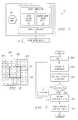
- FIG. 1is a block diagram of an imaging system employing an image correcting system in accordance with the present invention
- FIG. 2is an exemplary defect map showing dynamic correction region selection in accordance with the present invention
- FIG. 3illustrates a flowchart according to one implementation of the present invention
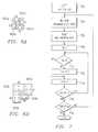
- FIG. 4illustrates correction subregions according to an implementation of the present invention
- FIG. 5illustrates a flowchart of subregion selection according to an implementation of the present invention
- FIGS. 6A and 6Billustrate subregion selection according to an implementation of the present invention.
- FIG. 7illustrates a flowchart of subregion selection according to another implementation of the invention.
- FIGS. 1-7illustrate an image defect correcting system and method of operation.
- an image defect correcting systemdynamically determines a correction area surrounding defective pixels.
- the correction regionis chosen to contain a predetermined percentage or number of non-defective pixels, which varies with the size of the region.
- the shape of the correction regionmay be varied to enhance the image correction process.
- the processing system 10provides enhanced image correction according to the present invention by varying the size and shape of a correction area around a pixel to be corrected.
- the processing system 10may be embodied as a known computer system, such as an IBM RS 6000 workstation, an Apple G4 computer, or as an IBM PC or PC-compatible computer.
- the processing system 10implements an image processing system 12 , such as a computer program.
- the processing system 10may further include an image input device 14 .
- the image input device 14may be embodied as a scanner, digital camera, or any other device suitable for providing an image to be processed, such as a mass storage device. It is noted that the image processing system 10 may be embodied as part of the image input device 14 , rather than, as illustrated, a separate unit. Thus, the figures are exemplary only.
- an exemplary image processing system 10is the image processing system described in co-pending U.S. patent application Ser. No. 09/686,719, titled Method and Apparatus for Differential-Illumination Image Capturing and Defect Handling, Attorney Docket No. ASF98-098-PA-US which is hereby incorporated by reference in its entirety as if fully set forth herein.
- the image processing system 12includes an image correcting system 15 including a correction region selection unit 16 and a replacement value selection unit 18 .
- the image correcting system 15uses a defect map 20 to perform image correction.
- One method for generating a defect mapis described in U.S. Pat. No. 5,266,805, which is hereby incorporated by reference in its entirety as if fully set forth herein. This method transmits infrared light at one surface of a film. A corresponding digitized infrared image is captured on this opposite side. Imperfections are identified because they substantially reduce or totally occlude the infrared light. The digitized infrared image thus provides an accurate map of the location and shape of image defects.
- Other methods of generating defect mapsare known and the invention is not intended to be limited to any particular method. Thus, the above discussion is by way of example only.
- pixelsare classified according to a binary defectiveness metric as defective or non-defective.
- a binary defectiveness metricis a level of defectiveness. If values for defectiveness are normalized between 0 for defective and 1 for non-defective, a pixel with a value of 0.5 would be considered half defective.
- An alternative defectiveness metricis correctability, which is a metric indicating how susceptible a pixel is to a particular method for correction. For example, a pixel might be assigned a correctability of 1, meaning 100% correctable, if it can be corrected using the infrared subtractive technique, even though the defectiveness for that pixel may be only 0.5. For sake of simplicity, the following discussion will use defectiveness terminology, it being understood that other defectiveness metrics may be employed.
- the image correcting system 15selects a correction area proximate to each defective pixel.
- the correction areais selected to contain a predetermined percentage of non-defective pixels.
- the percentagevaries as a function of the size of the surrounding area, so that the percentage decreases as the size of the region increases. For example, in one implementation, the following formula is used to calculate the percentage of non-defective pixels:
- FIG. 2illustrates a defect map 200 .
- a pixel X to be correctedis denoted 201
- defective pixels 203are denoted d
- non-defective pixels 205are denoted n.
- ris chosen to be 1
- a box 202 surrounding the pixel 201needs 74% (or at least 7 out of 9) non-defective pixels in order to satisfy Equation 2.5.
- Equation 1indicates that box 204 requires only 33% (or at least 17 out of 49) non-defective pixels, and we see that the condition of Equation 2.5 is satisfied.
- a pixel reliabilityis defined, which is the inverse of a pixel s defect value.
- the pixel reliabilityis used as a gauge for a pixel s suitability for use as a substitute for the defective pixel in question.
- a pixel s reliabilityis calculated using the following formula:
- Ris the reliability
- Kis a proportionality constant determined empirically
- Equation 1may be used for determining the required percentage of non-defective pixels.
- the amplitudes of the pixels in the correction areaare used to determine a corrected amplitude value for the pixel which is to be corrected.
- a variety of methods for choosing the correction valuemay be employed.
- the amplitudes of the pixels in the correction regionmay be averaged to determine the correction value.
- a binary defect maponly the amplitudes of the non-defective pixels are used to determine the correction amplitude value. For example, if the correction areas 202 or 204 of FIG. 2 define binary defect maps, then the amplitudes of the defective pixels 203 are ignored in determining the correction value. Instead, only the amplitudes of the non-defective pixels 205 are used. According to one implementation, the median amplitude of all non-defective pixels is used as a substitute for the pixel 201 .
- Other mathematical techniquesmay be employed. For example, cubic spline techniques or similar mathematical models may be implemented.
- an amplitude valueis chosen based on an averaging of the values of pixels in the surrounding region, taking into account or weighting their reliabilities or defectiveness metrics.
- the valuemay be obtained by taking a mean or median average of those pixels having a particular reliability.
- FIG. 3A flowchart illustrating operation of one implementation of the present invention is shown in FIG. 3 .
- This flowchartrepresents the steps involved in correcting one pixel in the image, and as such would be repeated for each pixel in the entire image. In one implementation, only the original pixel values (and not the newly corrected pixel values) are used in any of these steps.
- the image correcting system 14sets the index value r equal to a predetermined index, such as 1.
- the image correcting system 14calculates the percentage of non-defective pixels allowed for that particular value of r. Alternatively, the image correcting system 14 may access a lookup table (not shown) which contains a list of values of r and corresponding percentages.
- the image correcting system 14determines the actual percentage of non-defective pixels. For example, the image correcting system 14 may count the non-defective pixels within the region defined by r. The actual percentage of non-defective pixels is compared to the calculated percentage of non-defective pixels in a step 308 . If the actual percentage is not greater than or equal to the calculated percentage, then in a step 310 , the index r is incremented and the program loops back to step 304 . However, if the actual percentage is greater than or equal to the calculated percentage, then in a step 312 , a correction value is determined by the image correcting system 14 .
- the image correcting programreplaces the defective pixel value with the calculated correction amplitude value, in a step 314 .
- the shape of the area surrounding the defective pixelmay also be varied.
- the shapeis varied while maintaining a center of gravity on the defective pixel (i.e., the defective pixel is maintained at the center of subregions weighted according to size and number of defective pixels).
- subregionsare created around the defective pixel which contain predetermined percentages of non-defective pixels.
- the subregionsare defined as rectangular quadrants of dimension r ⁇ (r+1), where r is the effective radius for the quadrant.
- the subregionsare described in terms of four rectangular regions, the subregions may have any of a variety of shapes.
- the subregionscan have effective radii which differ from one another depending upon the proportion of defective pixels within the particular subregion.
- a map 400 surrounding the defective pixel 399 (X)may be divided into subregions 401 - 404 (Q 1 -Q 4 ).
- the center of gravityis maintained by determining the number of non-defective pixels for a portion of each subregion associated with a particular increment of r.
- the sum of non-defective pixels (ND)is multiplied by its value of rand added vectorially to similar products from other subregions.
- the center of gravityis maintained by constraining the vector sum to be zero. For example, in the case of quadrants, +i is assigned to quadrant 401 (Q 1 ), ⁇ i can be assigned to quadrant 403 (Q 3 ), +j to quadrant 402 (Q 2 ), and j to quadrant 404 (Q 4 ), where i is the unit vector for the positive x-axis, and j is the unit vector for the positive y-axis. If the vector sum is nonzero, the radius is incremented for the appropriate quadrant to achieve the proper center of gravity.
- Equation 2For a binary defect map, ND for each quadrant is calculated using an equation similar to Equation 2 (i.e., the area A is now the area of the quadrant). For a continuous defect map, ND for each quadrant is calculated using an equation similar to Equation 4. In addition, a modified version of Equation 1, as seen below, is used to constrain the appropriate total percentage of non-defective pixels:
- NDP100*(1/(1 + ⁇ A /25)) Equation 6
- the area A in Equation 1is now the sum of the areas of each subregion.
- Equation 2.5is satisfied. If Equation 2.5 had not been satisfied, the index r would be incremented, and the above-described calculations undertaken again to determine whether the region(s) now satisfy the criteria of Equation 2.5. It is noted that a maximum number of iterations may constrain the image correction system to prevent hysteresis. Moreover, in certain cases, it may not be necessary for the vector sum VS to equal zero (0). Satisfactory image correcting performance may be achieved if VS meets a predetermined threshold value.
- each quadrantcontains 1 ⁇ 4 th of the total number of non-defective pixels. Initially, each quadrant is the same size. The sum of all non-defective pixels is then determined, and 1 ⁇ 4 of that value is used as a threshold for the next iteration of quadrant growth. If a quadrant has already contributed more than this threshold, it is not grown (i.e., r is not increased). Otherwise, r is incremented by 1. When all four quadrants are evaluated in this manner, a new sum of non-defective pixels is calculated and the process repeats. When the total number of non-defective pixels satisfies the requirement of Equation 1, then the process is finished with each quadrant contributing equally. In the case of a continuous defect map, the sum in question is the sum of reliability values for each pixel.
- FIG. 6A and 6Billustrate quadrant growth on the map of FIG. 4 .
- the radius, ris set to 1.
- ND1
- NDP74%.
- Quadrants 601 a - 604 aare of dimension 1 ⁇ 2; all quadrants except quadrant 604 a have two defective pixels.
- quadrant 601 d (Q 4 )is not grown, but quadrants 601 a - 601 c (Q 1 -Q 3 ) are.
- the threshold T2.25.
- the systemcalculates the sum of non-defective pixels (ND), the total required percentage (NDP) , and the threshold required of non-defective pixels per subregion (T).
- the sum of non-defective pixels (ND)is compared to the required percentage (NDP), as in Equation 2.5.
- step 708the index k is set to 1.
- step 710the sum of non-defective pixels for the quadrant associated with k (ND k ) is calculated and compared to the threshold, T. If ND k is less than T, then the radius for that quadrant (r k ) is incremented in step 712 . Otherwise, index k is incremented in step 714 .
- the new value of index kis compared against m in step 716 and if less than or equal to m, control is returned to step 710 . Otherwise, step 716 checks the flag F. If F is FALSE, control is returned to step 704 . Otherwise, the process is finished for the current pixel.
- a substitute value for the amplitude of the pixel 399is calculated by first determining a figure of merit for each pixel in a subregion once the size and shape of the subregions are determined.
- the figure of meritindicates the appropriateness of using that pixel as a substitute.
- One particular figure of meritis shown below:
- FM kis the figure of merit
- R kis the reliability
- the pixel with the highest figure of meritis selected.
- FM kis the figure of merit for the selected pixel from the k th subregion
- FM tis the total figure of merit.
- P kis the amplitude of the selected pixel from the k th subregion
Landscapes
- Physics & Mathematics (AREA)
- Engineering & Computer Science (AREA)
- Nonlinear Science (AREA)
- General Physics & Mathematics (AREA)
- Crystallography & Structural Chemistry (AREA)
- Optics & Photonics (AREA)
- Chemical & Material Sciences (AREA)
- Multimedia (AREA)
- Signal Processing (AREA)
- Theoretical Computer Science (AREA)
- Mathematical Physics (AREA)
- Facsimile Image Signal Circuits (AREA)
- Transforming Light Signals Into Electric Signals (AREA)
Abstract
Description


Claims (32)
Priority Applications (1)
| Application Number | Priority Date | Filing Date | Title |
|---|---|---|---|
| US09/679,990US6614946B1 (en) | 1999-10-08 | 2000-10-05 | System and method for correcting defects in digital images through selective fill-in from surrounding areas |
Applications Claiming Priority (2)
| Application Number | Priority Date | Filing Date | Title |
|---|---|---|---|
| US15850199P | 1999-10-08 | 1999-10-08 | |
| US09/679,990US6614946B1 (en) | 1999-10-08 | 2000-10-05 | System and method for correcting defects in digital images through selective fill-in from surrounding areas |
Publications (1)
| Publication Number | Publication Date |
|---|---|
| US6614946B1true US6614946B1 (en) | 2003-09-02 |
Family
ID=22568418
Family Applications (1)
| Application Number | Title | Priority Date | Filing Date |
|---|---|---|---|
| US09/679,990Expired - LifetimeUS6614946B1 (en) | 1999-10-08 | 2000-10-05 | System and method for correcting defects in digital images through selective fill-in from surrounding areas |
Country Status (3)
| Country | Link |
|---|---|
| US (1) | US6614946B1 (en) |
| AU (1) | AU1962701A (en) |
| WO (1) | WO2001027688A2 (en) |
Cited By (14)
| Publication number | Priority date | Publication date | Assignee | Title |
|---|---|---|---|---|
| US20020065611A1 (en)* | 2000-11-24 | 2002-05-30 | Stefan Boehm | Method for operating an image system of an imaging medical examination device and medical examination device |
| US20030053140A1 (en)* | 2001-09-19 | 2003-03-20 | Pfu Limited | Method of controlling image reading system and control program thereof |
| US6768512B1 (en)* | 2000-07-12 | 2004-07-27 | Vanguard International Semiconductor Corp. | Method of bad pixel correction |
| US20060161806A1 (en)* | 2005-01-18 | 2006-07-20 | Tatjana Gromyko | Method and system of configuring a software program |
| US20070248168A1 (en)* | 1997-07-30 | 2007-10-25 | Lg Electronics Inc. | Method of reducing a blocking artifact when coding moving picture |
| US20100142848A1 (en)* | 2005-11-18 | 2010-06-10 | Abbott Laboratories | Image Based Correction For Unwanted Light Signals In A Specific Region Of Interest |
| USRE42516E1 (en) | 1997-09-09 | 2011-07-05 | Video Enhancement Solutions, LLC | Method of removing blocking artifacts in a coding system of a moving picture |
| US8023766B1 (en) | 2007-04-30 | 2011-09-20 | Hewlett-Packard Development Company, L.P. | Method and system of processing an image containing undesirable pixels |
| US8170350B2 (en) | 2004-08-16 | 2012-05-01 | DigitalOptics Corporation Europe Limited | Foreground/background segmentation in digital images |
| WO2017209675A1 (en) | 2016-05-30 | 2017-12-07 | Fingerprint Cards Ab | Correction and detection of defective capacitive sensor elements of a fingerprint sensor |
| CN108845438A (en)* | 2018-04-19 | 2018-11-20 | 苏州华兴源创电子科技有限公司 | LCD panel test device and method |
| JP2020008488A (en)* | 2018-07-11 | 2020-01-16 | オムロン株式会社 | Image processing apparatus, image processing method, and image processing program |
| CN111093465A (en)* | 2017-11-06 | 2020-05-01 | Hoya株式会社 | Electronic endoscope processor and electronic endoscope system |
| US20220237775A1 (en)* | 2021-01-27 | 2022-07-28 | Canon Kabushiki Kaisha | Radiographic imaging system, radiographic imaging apparatus, and inspection method for inspecting radiographic imaging apparatus |
Families Citing this family (5)
| Publication number | Priority date | Publication date | Assignee | Title |
|---|---|---|---|---|
| US20030039402A1 (en)* | 2001-08-24 | 2003-02-27 | Robins David R. | Method and apparatus for detection and removal of scanned image scratches and dust |
| US20030039403A1 (en)* | 2001-08-24 | 2003-02-27 | Robins David R. | Method and system for user assisted defect removal |
| KR100407158B1 (en)* | 2002-02-07 | 2003-11-28 | 삼성탈레스 주식회사 | Method for correcting time variant defect in thermal image system |
| US7499599B2 (en)* | 2003-06-12 | 2009-03-03 | General Electric Company | Method of real-time correction of non-functioning pixels in digital radiography |
| JP3952301B2 (en)* | 2003-08-29 | 2007-08-01 | ノーリツ鋼機株式会社 | Image processing apparatus, method, and program |
Citations (96)
| Publication number | Priority date | Publication date | Assignee | Title |
|---|---|---|---|---|
| DE2821868A1 (en) | 1978-05-19 | 1979-11-22 | Karl Sirowatka | Recording damage on moving film or bands - using infrared scanning and pen recorders or warning devices |
| US4260899A (en) | 1979-06-14 | 1981-04-07 | Intec Corporation | Wide web laser scanner flaw detection method and apparatus |
| US4301469A (en) | 1980-04-30 | 1981-11-17 | United Technologies Corporation | Run length encoder for color raster scanner |
| US4302108A (en) | 1979-01-29 | 1981-11-24 | Polaroid Corporation | Detection of subsurface defects by reflection interference |
| US4462860A (en) | 1982-05-24 | 1984-07-31 | At&T Bell Laboratories | End point detection |
| US4670779A (en) | 1984-01-10 | 1987-06-02 | Sharp Kabushiki Kaisha | Color-picture analyzing apparatus with red-purpose and green-purpose filters |
| US4677465A (en) | 1985-11-01 | 1987-06-30 | Eastman Kodak Company | Digital color image processing method with shape correction of histograms used to produce color reproduction functions |
| US4680638A (en) | 1982-07-16 | 1987-07-14 | British Broadcasting Corporation | Concealment of defects in a video signal |
| US4700229A (en) | 1985-07-09 | 1987-10-13 | U.S. Philips Corporation | Image enhancement circuit |
| US4775238A (en) | 1985-09-24 | 1988-10-04 | Erwin Sick Gmbh Optik-Elektronik | Optical web monitoring apparatus |
| US4796061A (en) | 1985-11-16 | 1989-01-03 | Dainippon Screen Mfg. Co., Ltd. | Device for detachably attaching a film onto a drum in a drum type picture scanning recording apparatus |
| US4814630A (en) | 1987-06-29 | 1989-03-21 | Ncr Corporation | Document illuminating apparatus using light sources A, B, and C in periodic arrays |
| US4821114A (en) | 1986-05-02 | 1989-04-11 | Dr. Ing. Rudolf Hell Gmbh | Opto-electronic scanning arrangement |
| US4845551A (en) | 1985-05-31 | 1989-07-04 | Fuji Photo Film Co., Ltd. | Method for correcting color photographic image data on the basis of calibration data read from a reference film |
| US4933566A (en) | 1987-11-30 | 1990-06-12 | Fuji Photo Film Co., Ltd. | Method of detecting tape defects |
| US4937720A (en) | 1989-10-13 | 1990-06-26 | Sundstrand Corporation | PWM inverter circuit analytically compensating for DC link distortion |
| US4969045A (en) | 1988-05-20 | 1990-11-06 | Sanyo Electric Co., Ltd. | Image sensing apparatus having automatic iris function of automatically adjusting exposure in response to video signal |
| US4972091A (en) | 1989-05-16 | 1990-11-20 | Canadian Patents And Development Limited/Societe Canadienne Des Brevets Et D'exploitation Limitee | Method and apparatus for detecting the presence of flaws in a moving sheet of material |
| US4989973A (en) | 1988-10-03 | 1991-02-05 | Nissan Motor Co., Ltd. | Surface condition estimating apparatus |
| US4994918A (en) | 1989-04-28 | 1991-02-19 | Bts Broadcast Television Systems Gmbh | Method and circuit for the automatic correction of errors in image steadiness during film scanning |
| US5003379A (en) | 1989-10-16 | 1991-03-26 | Eastman Kodak Company | Telecine scanning apparatus with spectrally-shifted sensitivities responsive to negative or print film dyes |
| EP0422220A1 (en) | 1989-03-28 | 1991-04-17 | Yokogawa Medical Systems, Ltd | Image processing apparatus |
| US5010401A (en) | 1988-08-11 | 1991-04-23 | Mitsubishi Denki Kabushiki Kaisha | Picture coding and decoding apparatus using vector quantization |
| US5047968A (en) | 1988-03-04 | 1991-09-10 | University Of Massachusetts Medical Center | Iterative image restoration device |
| US5058982A (en) | 1989-06-21 | 1991-10-22 | Orbot Systems Ltd. | Illumination system and inspection apparatus including same |
| US5091972A (en) | 1990-09-17 | 1992-02-25 | Eastman Kodak Company | System and method for reducing digital image noise |
| US5097521A (en) | 1989-12-21 | 1992-03-17 | Bts Broadcast Television Systems Gmbh | Method of concealing scratch errors in a video signal derived from a film scanner |
| EP0482790A1 (en) | 1990-10-23 | 1992-04-29 | Crosfield Electronics Limited | Method and apparatus for generating representation of an image |
| US5149960A (en) | 1991-07-03 | 1992-09-22 | R. R. Donnelley & Sons Company | Method of converting scanner signals into colorimetric signals |
| US5155596A (en) | 1990-12-03 | 1992-10-13 | Eastman Kodak Company | Film scanner illumination system having an automatic light control |
| JPH04291139A (en) | 1991-03-20 | 1992-10-15 | Nippon Steel Corp | Strip defect notification device |
| EP0527097A2 (en) | 1991-08-06 | 1993-02-10 | Eastman Kodak Company | Apparatus and method for collectively performing tile-based image rotation, scaling and digital halftone screening |
| US5200817A (en) | 1991-08-29 | 1993-04-06 | Xerox Corporation | Conversion of an RGB color scanner into a colorimetric scanner |
| EP0569142A1 (en) | 1992-05-05 | 1993-11-10 | International Business Machines Corporation | System and method for image recovery |
| US5267030A (en) | 1989-12-22 | 1993-11-30 | Eastman Kodak Company | Method and associated apparatus for forming image data metrics which achieve media compatibility for subsequent imaging application |
| US5291286A (en) | 1988-02-29 | 1994-03-01 | Mitsubishi Denki Kabushiki Kaisha | Multimedia data transmission system |
| US5311310A (en) | 1991-12-06 | 1994-05-10 | Bell Communications Research, Inc. | High efficiency coder and method employing overlapped motion compensation and perfect reconstruction filter banks |
| US5317420A (en)* | 1992-03-05 | 1994-05-31 | Matsushita Electric Industrial Co., Ltd. | Noise elimination apparatus for eliminating noise components having a high density and a low density |
| US5335086A (en) | 1990-11-22 | 1994-08-02 | Dainippon Screen Mfg. Co., Ltd | Method of and apparatus for eliminating pin holes |
| EP0624848A2 (en) | 1993-05-04 | 1994-11-17 | Eastman Kodak Company | A technique for the detection and removal of local defects in digital continuous-tone images |
| US5371542A (en) | 1992-06-23 | 1994-12-06 | The United States Of America As Represented By The Secretary Of The Navy | Dual waveband signal processing system |
| GB2283633A (en) | 1993-11-05 | 1995-05-10 | Sony Uk Ltd | Video image manipulation; controling anti-alias filter for segmented output image |
| US5448380A (en) | 1993-07-31 | 1995-09-05 | Samsung Electronics Co., Ltd. | color image processing method and apparatus for correcting a color signal from an input image device |
| US5447811A (en) | 1992-09-24 | 1995-09-05 | Eastman Kodak Company | Color image reproduction of scenes with preferential tone mapping |
| US5452018A (en) | 1991-04-19 | 1995-09-19 | Sony Electronics Inc. | Digital color correction system having gross and fine adjustment modes |
| US5465155A (en) | 1992-07-17 | 1995-11-07 | International Business Machines Corporation | Duplex film scanning |
| US5465163A (en) | 1991-03-18 | 1995-11-07 | Canon Kabushiki Kaisha | Image processing method and apparatus for processing oversized original images and for synthesizing multiple images |
| US5477345A (en) | 1993-12-15 | 1995-12-19 | Xerox Corporation | Apparatus for subsampling chrominance |
| EP0699753A2 (en) | 1994-07-13 | 1996-03-06 | Hoechst Aktiengesellschaft | Protein for the transport of cationic xenobiotic and/or pharmaceutical compounds, DNA sequences coding therefore and its uses |
| US5509086A (en) | 1993-12-23 | 1996-04-16 | International Business Machines Corporation | Automatic cross color elimination |
| US5516608A (en) | 1994-02-28 | 1996-05-14 | International Business Machines Corporation | Method for controlling a line dimension arising in photolithographic processes |
| EP0716538A2 (en) | 1994-12-06 | 1996-06-12 | Canon Kabushiki Kaisha | Image pickup device |
| US5552904A (en) | 1994-01-31 | 1996-09-03 | Samsung Electronics Co., Ltd. | Color correction method and apparatus using adaptive region separation |
| US5561611A (en) | 1994-10-04 | 1996-10-01 | Noran Instruments, Inc. | Method and apparatus for signal restoration without knowledge of the impulse response function of the signal acquisition system |
| US5565931A (en) | 1994-10-31 | 1996-10-15 | Vivo Software. Inc. | Method and apparatus for applying gamma predistortion to a color image signal |
| US5568270A (en) | 1992-12-09 | 1996-10-22 | Fuji Photo Film Co., Ltd. | Image reading apparatus which varies reading time according to image density |
| US5581376A (en) | 1994-08-29 | 1996-12-03 | Xerox Corporation | System for correcting color images using tetrahedral interpolation over a hexagonal lattice |
| US5582961A (en) | 1995-06-06 | 1996-12-10 | Eastman Kodak Company | Photographic elements which achieve colorimetrically accurate recording |
| US5583950A (en) | 1992-09-16 | 1996-12-10 | Mikos, Ltd. | Method and apparatus for flash correlation |
| US5589887A (en) | 1994-09-15 | 1996-12-31 | U.S. Philips Corporation | Method and circuit for detecting and concealing video signal errors |
| EP0751670A2 (en) | 1995-06-29 | 1997-01-02 | Bayer Corporation | Optical path for a scanning system |
| US5608547A (en) | 1993-04-22 | 1997-03-04 | Minolta Camera Kabushiki Kaisha | Image forming apparatus having illumination direction altered for every plurality of readout operations with respect to one original |
| EP0768621A2 (en) | 1995-10-16 | 1997-04-16 | Eastman Kodak Company | Method and apparatus for correcting pixel values in a digital image |
| US5641596A (en) | 1995-12-05 | 1997-06-24 | Eastman Kodak Company | Adjusting film grain properties in digital images |
| US5666443A (en) | 1993-08-24 | 1997-09-09 | Minolta Co., Ltd. | Image processor with edge emphasis of image data |
| EP0794454A2 (en) | 1996-03-04 | 1997-09-10 | Fuji Photo Film Co., Ltd. | Film scanner |
| DE19636867C1 (en) | 1996-09-11 | 1998-01-02 | Philips Patentverwaltung | Video signal processing apparatus for noise signal removal |
| EP0816833A2 (en) | 1996-06-28 | 1998-01-07 | Fujifilm Electronic Imaging Limited | An illumination unit and illumination method |
| US5721624A (en) | 1989-10-15 | 1998-02-24 | Minolta Co., Ltd. | Image reading apparatus improving the joining state of a plurality of image data obtained by dividing and reading out an original image |
| US5726773A (en) | 1994-11-29 | 1998-03-10 | Carl-Zeiss-Stiftung | Apparatus for scanning and digitizing photographic image objects and method of operating said apparatus |
| US5729631A (en) | 1993-11-30 | 1998-03-17 | Polaroid Corporation | Image noise reduction system using a wiener variant filter in a pyramid image representation |
| US5771107A (en) | 1995-01-11 | 1998-06-23 | Mita Industrial Co., Ltd. | Image processor with image edge emphasizing capability |
| US5808674A (en) | 1996-09-09 | 1998-09-15 | Eastman Kodak Company | Producing and improved digital image from digital signals corresponding to pairs of photosites |
| EP0893914A2 (en) | 1997-07-24 | 1999-01-27 | Nikon Corporation | Image processing method, image processing apparatus, and storage medium for storing control process |
| US5892595A (en) | 1996-01-26 | 1999-04-06 | Ricoh Company, Ltd. | Image reading apparatus for correct positioning of color component values of each picture element |
| JPH11185028A (en) | 1997-10-14 | 1999-07-09 | Hewlett Packard Co <Hp> | Method for detecting artifact on surface of transmissive image medium |
| US5923042A (en) | 1994-10-11 | 1999-07-13 | International Business Machines Corporation | Method and apparatus for optically scanning transparent media |
| EP0930498A2 (en) | 1997-12-26 | 1999-07-21 | Nidek Co., Ltd. | Inspection apparatus and method for detecting defects |
| US5930388A (en) | 1996-10-24 | 1999-07-27 | Sharp Kabuskiki Kaisha | Color image processing apparatus |
| US5963662A (en) | 1996-08-07 | 1999-10-05 | Georgia Tech Research Corporation | Inspection system and method for bond detection and validation of surface mount devices |
| US5979011A (en) | 1995-04-07 | 1999-11-09 | Noritsu Koki Co., Ltd | Dust removing apparatus |
| US5982951A (en) | 1996-05-28 | 1999-11-09 | Canon Kabushiki Kaisha | Apparatus and method for combining a plurality of images |
| US5982941A (en) | 1997-02-07 | 1999-11-09 | Eastman Kodak Company | Method of producing digital image with improved performance characteristic |
| US5991444A (en) | 1994-11-14 | 1999-11-23 | Sarnoff Corporation | Method and apparatus for performing mosaic based image compression |
| US6005987A (en) | 1996-10-17 | 1999-12-21 | Sharp Kabushiki Kaisha | Picture image forming apparatus |
| JP2000013604A (en) | 1998-04-22 | 2000-01-14 | Nikon Corp | Image processing apparatus and storage medium for storing control procedure of image processing apparatus |
| US6057040A (en) | 1998-01-22 | 2000-05-02 | Vision--Ease Lens, Inc. | Aminosilane coating composition and process for producing coated articles |
| US6075905A (en) | 1996-07-17 | 2000-06-13 | Sarnoff Corporation | Method and apparatus for mosaic image construction |
| US6078051A (en) | 1998-01-08 | 2000-06-20 | Xerox Corporation | Image input device and method for providing scanning artifact detection |
| US6078701A (en) | 1997-08-01 | 2000-06-20 | Sarnoff Corporation | Method and apparatus for performing local to global multiframe alignment to construct mosaic images |
| JP2000196813A (en) | 1998-12-25 | 2000-07-14 | Canon Inc | Image reading device |
| US6101273A (en) | 1995-10-31 | 2000-08-08 | Fuji Photo Film Co., Ltd. | Image reproducing method and apparatus |
| US6128416A (en) | 1993-09-10 | 2000-10-03 | Olympus Optical Co., Ltd. | Image composing technique for optimally composing a single image from a plurality of digital images |
| US6239886B1 (en) | 1998-01-08 | 2001-05-29 | Xerox Corporation | Method and apparatus for correcting luminance and chrominance data in digital color images |
| US6529618B1 (en)* | 1998-09-04 | 2003-03-04 | Konica Corporation | Radiation image processing apparatus |
| EP1547811A2 (en) | 1999-07-20 | 2005-06-29 | TECNOFORMING S.p.A. | Light alloy rim with a front covering element in stainless steel and its production method |
Family Cites Families (1)
| Publication number | Priority date | Publication date | Assignee | Title |
|---|---|---|---|---|
| JP3442466B2 (en)* | 1993-04-12 | 2003-09-02 | 株式会社リコー | Image processing apparatus and image processing method |
- 2000
- 2000-10-05AUAU19627/01Apatent/AU1962701A/ennot_activeAbandoned
- 2000-10-05USUS09/679,990patent/US6614946B1/ennot_activeExpired - Lifetime
- 2000-10-05WOPCT/US2000/041087patent/WO2001027688A2/enactiveApplication Filing
Patent Citations (102)
| Publication number | Priority date | Publication date | Assignee | Title |
|---|---|---|---|---|
| DE2821868A1 (en) | 1978-05-19 | 1979-11-22 | Karl Sirowatka | Recording damage on moving film or bands - using infrared scanning and pen recorders or warning devices |
| US4302108A (en) | 1979-01-29 | 1981-11-24 | Polaroid Corporation | Detection of subsurface defects by reflection interference |
| US4260899A (en) | 1979-06-14 | 1981-04-07 | Intec Corporation | Wide web laser scanner flaw detection method and apparatus |
| US4301469A (en) | 1980-04-30 | 1981-11-17 | United Technologies Corporation | Run length encoder for color raster scanner |
| US4462860A (en) | 1982-05-24 | 1984-07-31 | At&T Bell Laboratories | End point detection |
| US4680638A (en) | 1982-07-16 | 1987-07-14 | British Broadcasting Corporation | Concealment of defects in a video signal |
| US4670779A (en) | 1984-01-10 | 1987-06-02 | Sharp Kabushiki Kaisha | Color-picture analyzing apparatus with red-purpose and green-purpose filters |
| US4845551A (en) | 1985-05-31 | 1989-07-04 | Fuji Photo Film Co., Ltd. | Method for correcting color photographic image data on the basis of calibration data read from a reference film |
| US4700229A (en) | 1985-07-09 | 1987-10-13 | U.S. Philips Corporation | Image enhancement circuit |
| US4775238A (en) | 1985-09-24 | 1988-10-04 | Erwin Sick Gmbh Optik-Elektronik | Optical web monitoring apparatus |
| US4677465A (en) | 1985-11-01 | 1987-06-30 | Eastman Kodak Company | Digital color image processing method with shape correction of histograms used to produce color reproduction functions |
| US4796061A (en) | 1985-11-16 | 1989-01-03 | Dainippon Screen Mfg. Co., Ltd. | Device for detachably attaching a film onto a drum in a drum type picture scanning recording apparatus |
| US4821114A (en) | 1986-05-02 | 1989-04-11 | Dr. Ing. Rudolf Hell Gmbh | Opto-electronic scanning arrangement |
| US4814630A (en) | 1987-06-29 | 1989-03-21 | Ncr Corporation | Document illuminating apparatus using light sources A, B, and C in periodic arrays |
| US4933566A (en) | 1987-11-30 | 1990-06-12 | Fuji Photo Film Co., Ltd. | Method of detecting tape defects |
| US5291286A (en) | 1988-02-29 | 1994-03-01 | Mitsubishi Denki Kabushiki Kaisha | Multimedia data transmission system |
| US5047968A (en) | 1988-03-04 | 1991-09-10 | University Of Massachusetts Medical Center | Iterative image restoration device |
| US4969045A (en) | 1988-05-20 | 1990-11-06 | Sanyo Electric Co., Ltd. | Image sensing apparatus having automatic iris function of automatically adjusting exposure in response to video signal |
| US5010401A (en) | 1988-08-11 | 1991-04-23 | Mitsubishi Denki Kabushiki Kaisha | Picture coding and decoding apparatus using vector quantization |
| US4989973A (en) | 1988-10-03 | 1991-02-05 | Nissan Motor Co., Ltd. | Surface condition estimating apparatus |
| EP0422220A1 (en) | 1989-03-28 | 1991-04-17 | Yokogawa Medical Systems, Ltd | Image processing apparatus |
| US4994918A (en) | 1989-04-28 | 1991-02-19 | Bts Broadcast Television Systems Gmbh | Method and circuit for the automatic correction of errors in image steadiness during film scanning |
| US4972091A (en) | 1989-05-16 | 1990-11-20 | Canadian Patents And Development Limited/Societe Canadienne Des Brevets Et D'exploitation Limitee | Method and apparatus for detecting the presence of flaws in a moving sheet of material |
| US5058982A (en) | 1989-06-21 | 1991-10-22 | Orbot Systems Ltd. | Illumination system and inspection apparatus including same |
| US4937720A (en) | 1989-10-13 | 1990-06-26 | Sundstrand Corporation | PWM inverter circuit analytically compensating for DC link distortion |
| US5721624A (en) | 1989-10-15 | 1998-02-24 | Minolta Co., Ltd. | Image reading apparatus improving the joining state of a plurality of image data obtained by dividing and reading out an original image |
| US5003379A (en) | 1989-10-16 | 1991-03-26 | Eastman Kodak Company | Telecine scanning apparatus with spectrally-shifted sensitivities responsive to negative or print film dyes |
| US5097521A (en) | 1989-12-21 | 1992-03-17 | Bts Broadcast Television Systems Gmbh | Method of concealing scratch errors in a video signal derived from a film scanner |
| US5267030A (en) | 1989-12-22 | 1993-11-30 | Eastman Kodak Company | Method and associated apparatus for forming image data metrics which achieve media compatibility for subsequent imaging application |
| US5091972A (en) | 1990-09-17 | 1992-02-25 | Eastman Kodak Company | System and method for reducing digital image noise |
| EP0482790A1 (en) | 1990-10-23 | 1992-04-29 | Crosfield Electronics Limited | Method and apparatus for generating representation of an image |
| EP0482790B1 (en) | 1990-10-23 | 1996-01-03 | Crosfield Electronics Limited | Method and apparatus for generating representation of an image |
| US5335086A (en) | 1990-11-22 | 1994-08-02 | Dainippon Screen Mfg. Co., Ltd | Method of and apparatus for eliminating pin holes |
| US5155596A (en) | 1990-12-03 | 1992-10-13 | Eastman Kodak Company | Film scanner illumination system having an automatic light control |
| US5465163A (en) | 1991-03-18 | 1995-11-07 | Canon Kabushiki Kaisha | Image processing method and apparatus for processing oversized original images and for synthesizing multiple images |
| JPH04291139A (en) | 1991-03-20 | 1992-10-15 | Nippon Steel Corp | Strip defect notification device |
| US5452018A (en) | 1991-04-19 | 1995-09-19 | Sony Electronics Inc. | Digital color correction system having gross and fine adjustment modes |
| US5149960B1 (en) | 1991-07-03 | 1994-08-30 | Donnelly R R & Sons | Method of converting scanner signals into colorimetric signals |
| US5149960A (en) | 1991-07-03 | 1992-09-22 | R. R. Donnelley & Sons Company | Method of converting scanner signals into colorimetric signals |
| EP0527097A2 (en) | 1991-08-06 | 1993-02-10 | Eastman Kodak Company | Apparatus and method for collectively performing tile-based image rotation, scaling and digital halftone screening |
| US5200817A (en) | 1991-08-29 | 1993-04-06 | Xerox Corporation | Conversion of an RGB color scanner into a colorimetric scanner |
| US5311310A (en) | 1991-12-06 | 1994-05-10 | Bell Communications Research, Inc. | High efficiency coder and method employing overlapped motion compensation and perfect reconstruction filter banks |
| US5317420A (en)* | 1992-03-05 | 1994-05-31 | Matsushita Electric Industrial Co., Ltd. | Noise elimination apparatus for eliminating noise components having a high density and a low density |
| US5266805A (en) | 1992-05-05 | 1993-11-30 | International Business Machines Corporation | System and method for image recovery |
| EP0569142A1 (en) | 1992-05-05 | 1993-11-10 | International Business Machines Corporation | System and method for image recovery |
| US5371542A (en) | 1992-06-23 | 1994-12-06 | The United States Of America As Represented By The Secretary Of The Navy | Dual waveband signal processing system |
| US5465155A (en) | 1992-07-17 | 1995-11-07 | International Business Machines Corporation | Duplex film scanning |
| US5583950A (en) | 1992-09-16 | 1996-12-10 | Mikos, Ltd. | Method and apparatus for flash correlation |
| US5447811A (en) | 1992-09-24 | 1995-09-05 | Eastman Kodak Company | Color image reproduction of scenes with preferential tone mapping |
| US5568270A (en) | 1992-12-09 | 1996-10-22 | Fuji Photo Film Co., Ltd. | Image reading apparatus which varies reading time according to image density |
| US5608547A (en) | 1993-04-22 | 1997-03-04 | Minolta Camera Kabushiki Kaisha | Image forming apparatus having illumination direction altered for every plurality of readout operations with respect to one original |
| EP0624848A2 (en) | 1993-05-04 | 1994-11-17 | Eastman Kodak Company | A technique for the detection and removal of local defects in digital continuous-tone images |
| US5448380A (en) | 1993-07-31 | 1995-09-05 | Samsung Electronics Co., Ltd. | color image processing method and apparatus for correcting a color signal from an input image device |
| US5666443A (en) | 1993-08-24 | 1997-09-09 | Minolta Co., Ltd. | Image processor with edge emphasis of image data |
| US6128416A (en) | 1993-09-10 | 2000-10-03 | Olympus Optical Co., Ltd. | Image composing technique for optimally composing a single image from a plurality of digital images |
| GB2283633A (en) | 1993-11-05 | 1995-05-10 | Sony Uk Ltd | Video image manipulation; controling anti-alias filter for segmented output image |
| US5729631A (en) | 1993-11-30 | 1998-03-17 | Polaroid Corporation | Image noise reduction system using a wiener variant filter in a pyramid image representation |
| US5477345A (en) | 1993-12-15 | 1995-12-19 | Xerox Corporation | Apparatus for subsampling chrominance |
| US5509086A (en) | 1993-12-23 | 1996-04-16 | International Business Machines Corporation | Automatic cross color elimination |
| US5673336A (en) | 1993-12-23 | 1997-09-30 | International Business Machines Corporation | Automatic cross color elimination |
| US5552904A (en) | 1994-01-31 | 1996-09-03 | Samsung Electronics Co., Ltd. | Color correction method and apparatus using adaptive region separation |
| US5516608A (en) | 1994-02-28 | 1996-05-14 | International Business Machines Corporation | Method for controlling a line dimension arising in photolithographic processes |
| EP0699753A2 (en) | 1994-07-13 | 1996-03-06 | Hoechst Aktiengesellschaft | Protein for the transport of cationic xenobiotic and/or pharmaceutical compounds, DNA sequences coding therefore and its uses |
| US5581376A (en) | 1994-08-29 | 1996-12-03 | Xerox Corporation | System for correcting color images using tetrahedral interpolation over a hexagonal lattice |
| US5589887A (en) | 1994-09-15 | 1996-12-31 | U.S. Philips Corporation | Method and circuit for detecting and concealing video signal errors |
| US5561611A (en) | 1994-10-04 | 1996-10-01 | Noran Instruments, Inc. | Method and apparatus for signal restoration without knowledge of the impulse response function of the signal acquisition system |
| US5923042A (en) | 1994-10-11 | 1999-07-13 | International Business Machines Corporation | Method and apparatus for optically scanning transparent media |
| US5565931A (en) | 1994-10-31 | 1996-10-15 | Vivo Software. Inc. | Method and apparatus for applying gamma predistortion to a color image signal |
| US5991444A (en) | 1994-11-14 | 1999-11-23 | Sarnoff Corporation | Method and apparatus for performing mosaic based image compression |
| US5726773A (en) | 1994-11-29 | 1998-03-10 | Carl-Zeiss-Stiftung | Apparatus for scanning and digitizing photographic image objects and method of operating said apparatus |
| EP0716538A2 (en) | 1994-12-06 | 1996-06-12 | Canon Kabushiki Kaisha | Image pickup device |
| US5771107A (en) | 1995-01-11 | 1998-06-23 | Mita Industrial Co., Ltd. | Image processor with image edge emphasizing capability |
| US5979011A (en) | 1995-04-07 | 1999-11-09 | Noritsu Koki Co., Ltd | Dust removing apparatus |
| US5582961A (en) | 1995-06-06 | 1996-12-10 | Eastman Kodak Company | Photographic elements which achieve colorimetrically accurate recording |
| EP0751670A2 (en) | 1995-06-29 | 1997-01-02 | Bayer Corporation | Optical path for a scanning system |
| EP0768621A2 (en) | 1995-10-16 | 1997-04-16 | Eastman Kodak Company | Method and apparatus for correcting pixel values in a digital image |
| US6101273A (en) | 1995-10-31 | 2000-08-08 | Fuji Photo Film Co., Ltd. | Image reproducing method and apparatus |
| US5641596A (en) | 1995-12-05 | 1997-06-24 | Eastman Kodak Company | Adjusting film grain properties in digital images |
| US5892595A (en) | 1996-01-26 | 1999-04-06 | Ricoh Company, Ltd. | Image reading apparatus for correct positioning of color component values of each picture element |
| EP0794454A2 (en) | 1996-03-04 | 1997-09-10 | Fuji Photo Film Co., Ltd. | Film scanner |
| US5982951A (en) | 1996-05-28 | 1999-11-09 | Canon Kabushiki Kaisha | Apparatus and method for combining a plurality of images |
| EP0816833A3 (en) | 1996-06-28 | 1998-08-26 | Fujifilm Electronic Imaging Limited | An illumination unit and illumination method |
| EP0816833A2 (en) | 1996-06-28 | 1998-01-07 | Fujifilm Electronic Imaging Limited | An illumination unit and illumination method |
| US6075905A (en) | 1996-07-17 | 2000-06-13 | Sarnoff Corporation | Method and apparatus for mosaic image construction |
| US5963662A (en) | 1996-08-07 | 1999-10-05 | Georgia Tech Research Corporation | Inspection system and method for bond detection and validation of surface mount devices |
| US5808674A (en) | 1996-09-09 | 1998-09-15 | Eastman Kodak Company | Producing and improved digital image from digital signals corresponding to pairs of photosites |
| DE19636867C1 (en) | 1996-09-11 | 1998-01-02 | Philips Patentverwaltung | Video signal processing apparatus for noise signal removal |
| US6005987A (en) | 1996-10-17 | 1999-12-21 | Sharp Kabushiki Kaisha | Picture image forming apparatus |
| US5930388A (en) | 1996-10-24 | 1999-07-27 | Sharp Kabuskiki Kaisha | Color image processing apparatus |
| US5982941A (en) | 1997-02-07 | 1999-11-09 | Eastman Kodak Company | Method of producing digital image with improved performance characteristic |
| EP0893914A2 (en) | 1997-07-24 | 1999-01-27 | Nikon Corporation | Image processing method, image processing apparatus, and storage medium for storing control process |
| US6078701A (en) | 1997-08-01 | 2000-06-20 | Sarnoff Corporation | Method and apparatus for performing local to global multiframe alignment to construct mosaic images |
| JPH11185028A (en) | 1997-10-14 | 1999-07-09 | Hewlett Packard Co <Hp> | Method for detecting artifact on surface of transmissive image medium |
| US5969372A (en) | 1997-10-14 | 1999-10-19 | Hewlett-Packard Company | Film scanner with dust and scratch correction by use of dark-field illumination |
| EP0930498A2 (en) | 1997-12-26 | 1999-07-21 | Nidek Co., Ltd. | Inspection apparatus and method for detecting defects |
| US6078051A (en) | 1998-01-08 | 2000-06-20 | Xerox Corporation | Image input device and method for providing scanning artifact detection |
| US6239886B1 (en) | 1998-01-08 | 2001-05-29 | Xerox Corporation | Method and apparatus for correcting luminance and chrominance data in digital color images |
| US6057040A (en) | 1998-01-22 | 2000-05-02 | Vision--Ease Lens, Inc. | Aminosilane coating composition and process for producing coated articles |
| JP2000013604A (en) | 1998-04-22 | 2000-01-14 | Nikon Corp | Image processing apparatus and storage medium for storing control procedure of image processing apparatus |
| US6529618B1 (en)* | 1998-09-04 | 2003-03-04 | Konica Corporation | Radiation image processing apparatus |
| JP2000196813A (en) | 1998-12-25 | 2000-07-14 | Canon Inc | Image reading device |
| EP1547811A2 (en) | 1999-07-20 | 2005-06-29 | TECNOFORMING S.p.A. | Light alloy rim with a front covering element in stainless steel and its production method |
Non-Patent Citations (11)
| Title |
|---|
| 2-D Adaptive Volterra Filter for 2-D Nonlinear Channel Equalisation and Image Restoration, J.N. Lin, et al., Electronic Letters, vol. 28, No. 2, Jan. 16, 1992, pp. 180-182. |
| A Regularized Iterative Image Restoration Algorithm, Aggelos K. Katsaggelos, et al., IEEE, 1991, pp. 914-929. |
| A Robust Method for Parameter Estimation of Signal-Dependent Noise Models in Digital Images, B. Aiazzi, et al., IEEE, 1997, pp. DSP 97-601-604. |
| About Digital ICE Technology, Applied Science Fiction, Inc., http://www.asf.com/html/o_products/icetech.html. Aug. 5, 1999. |
| Adaptive Fourier Threshold Filtering: A Method to Reduce Noise and Incoherent Artifacts in High Resolution Cardiac Images, M. Doyle, et al., 8306 Magnetic Resonance in Medicine, May, 31, 1994, No. 5, Baltimore, MD., pp. 546-550. |
| Adaptive-neighborhood filtering of images corrupted by signal-dependent noise, Rangaraj M. Rangayyan et al., Applied Optics, vol. 37, No. 20, Jul. 10, 1998, pp. 4477-4487. |
| Anisotropic Spectral Magnitude Estimation Filters for Noise Reduction and Image Enhancement, Til Aach, et al., IEEE, 1996, pp. 335-338. |
| Digital ICE, Applied Science Fiction, Inc., http://www.asf.com/html/o_products/iceprod.html. Aug. 5, 1999. |
| Digital Imaging Equipment White Papers, Putting Damaged Film on Ice, A Technical Discussion of Advances in Digital Imaging, Nikon Corporation, http://www.nikonusa.com/reference/whitepapers/imaging/ditechdisc.html, Aug. 5, 1999. |
| Local Cosine Transform-A Method for the Reduction of the Blocking Effect in JPEG, Gil Aharoni, et al., Journal of Mathematical Imaging and Vision, 3, 7-38, 1993. |
| New Adaptive Vector Filter Based on Noise Estimate, Mei Yu, et al., IEICE Trans. Fundamentals, vol. E82, No. 6, Jun., 1999. |
Cited By (70)
| Publication number | Priority date | Publication date | Assignee | Title |
|---|---|---|---|---|
| US20080192829A1 (en)* | 1997-07-30 | 2008-08-14 | Lg Electronics Inc. | Method of reducing a blocking artifact when coding moving picture |
| US7463786B2 (en) | 1997-07-30 | 2008-12-09 | Lg Electronics Inc. | Method of reducing a blocking artifact when coding moving picture |
| US9456221B2 (en) | 1997-07-30 | 2016-09-27 | Lg Electronics Inc. | Method of reducing a blocking artifact when coding moving picture |
| US8983225B2 (en) | 1997-07-30 | 2015-03-17 | Lg Electronics Inc. | Method of reducing a blocking artifact when coding moving picture |
| US7620262B2 (en) | 1997-07-30 | 2009-11-17 | Video Enhancement Solutions LLC | Method of reducing a blocking artifact when coding moving picture |
| US20070248168A1 (en)* | 1997-07-30 | 2007-10-25 | Lg Electronics Inc. | Method of reducing a blocking artifact when coding moving picture |
| US7616831B2 (en) | 1997-07-30 | 2009-11-10 | Video Enhancement Solutions | Method of reducing a blocking artifact when coding moving picture |
| US20070292043A1 (en)* | 1997-07-30 | 2007-12-20 | Lg Electronics Inc. | Method of reducing a blocking artifact when coding moving picture |
| US20080019442A1 (en)* | 1997-07-30 | 2008-01-24 | Lg Electronics Inc. | Method of reducing a blocking artifact when coding moving picture |
| US20080193040A1 (en)* | 1997-07-30 | 2008-08-14 | Lg Electronics Inc. | Method of reducing a blocking artifact when coding moving picture |
| US20080037638A1 (en)* | 1997-07-30 | 2008-02-14 | Lg Electronics Inc. | Method of reducing a blocking artifact when coding moving picture |
| US20080037629A1 (en)* | 1997-07-30 | 2008-02-14 | Lg Electronics Inc. | Method of reducing a blocking artifact when coding moving picture |
| US20080037625A1 (en)* | 1997-07-30 | 2008-02-14 | Lg Electronics Inc. | Method of reducing a blocking artifact when coding moving picture |
| US20080043838A1 (en)* | 1997-07-30 | 2008-02-21 | Lg Electronics Inc. | Method of reducing a blocking artifact when coding moving picture |
| US20080043854A1 (en)* | 1997-07-30 | 2008-02-21 | Lg Electronics Inc. | Method of reducing a blocking artifact when coding moving picture |
| US20080043837A1 (en)* | 1997-07-30 | 2008-02-21 | Lg Electronics Inc. | Method of reducing a blocking artifact when coding moving picture |
| US20080069472A1 (en)* | 1997-07-30 | 2008-03-20 | Lg Electronics Inc. | Method of reducing a blocking artifact when coding moving picture |
| US20080069222A1 (en)* | 1997-07-30 | 2008-03-20 | Lg Electronics Inc. | Method of reducing a blocking artifact when coding moving picture |
| US7379616B2 (en) | 1997-07-30 | 2008-05-27 | Lg Electronics Inc. | Method of reducing a blocking artifact when coding moving picture |
| US7379617B2 (en) | 1997-07-30 | 2008-05-27 | Lg Electronics Inc. | Method of reducing a blocking artifact when coding moving picture |
| US7382930B2 (en) | 1997-07-30 | 2008-06-03 | Lg Electronics Inc. | Method of reducing a blocking artifact when coding moving picture |
| US7391922B2 (en) | 1997-07-30 | 2008-06-24 | Lg Electronics Inc. | Method of reducing a blocking artifact when coding moving picture |
| US7391921B2 (en)* | 1997-07-30 | 2008-06-24 | Lg Electronics Inc. | Method of reducing a blocking artifact when coding moving picture |
| US7391924B2 (en) | 1997-07-30 | 2008-06-24 | Lg Electronics Inc. | Method of reducing a blocking artifact when coding moving picture |
| US7391923B2 (en) | 1997-07-30 | 2008-06-24 | Lg Electronics Inc. | Method of reducing a blocking artifact when coding moving picture |
| US7394945B2 (en) | 1997-07-30 | 2008-07-01 | Lg Electronics Inc. | Method of reducing a blocking artifact when coding moving picture |
| US7397967B2 (en) | 1997-07-30 | 2008-07-08 | Lg Electronics Inc. | Method of reducing a blocking artifact when coding moving picture |
| US7397965B2 (en) | 1997-07-30 | 2008-07-08 | Lg Electronics Inc. | Method of reducing a blocking artifact when coding moving picture |
| US7397966B2 (en) | 1997-07-30 | 2008-07-08 | Lg Electronics Inc. | Method of reducing a blocking artifact when coding moving picture |
| US7400780B2 (en) | 1997-07-30 | 2008-07-15 | Lg Electronics Inc. | Method of reducing a blocking artifact when coding moving picture |
| US7403667B2 (en)* | 1997-07-30 | 2008-07-22 | Lg Electronics Inc. | Method of reducing a blocking artifact when coding moving picture |
| US7406209B2 (en) | 1997-07-30 | 2008-07-29 | Lg Electronics Inc. | Method of reducing a blocking artifact when coding moving picture |
| US20080193039A1 (en)* | 1997-07-30 | 2008-08-14 | Lg Electronics Inc. | Method of reducing a blocking artifact when coding moving picture |
| US20080193038A1 (en)* | 1997-07-30 | 2008-08-14 | Lg Electronics Inc. | Method of reducing a blocking artifact when coding moving picture |
| US20070269131A1 (en)* | 1997-07-30 | 2007-11-22 | Lg Electronics Inc. | Method of reducing a blocking artifact when coding moving picture |
| US7616833B2 (en) | 1997-07-30 | 2009-11-10 | Video Enhancement Solutions LLC | Method of reducing a blocking artifact when coding moving picture |
| US20080037894A1 (en)* | 1997-07-30 | 2008-02-14 | Lg Electronics Inc. | Method of reducing a blocking artifact when coding moving picture |
| US20080212686A1 (en)* | 1997-07-30 | 2008-09-04 | Lg Electronics Inc. | Method of reducing a blocking artifact when coding moving picture |
| US7616832B2 (en) | 1997-07-30 | 2009-11-10 | Video Enhancement Solutions LLC | Method of reducing a blocking artifact when coding moving picture |
| US7454082B2 (en) | 1997-07-30 | 2008-11-18 | Lg Electronics Inc. | Method of reducing a blocking artifact when coding moving picture |
| US20080193041A1 (en)* | 1997-07-30 | 2008-08-14 | Lg Electronics Inc. | Method of reducing a blocking artifact when coding moving picture |
| US7492961B2 (en) | 1997-07-30 | 2009-02-17 | Lg Electronics Inc. | Method of reducing a blocking artifact when coding moving picture |
| US7492959B2 (en) | 1997-07-30 | 2009-02-17 | Lg Electronics Inc. | Method of reducing a blocking artifact when coding moving picture |
| US7492960B2 (en) | 1997-07-30 | 2009-02-17 | Lg Electronics Inc. | Method of reducing a blocking artifact when coding moving picture |
| US7496239B2 (en) | 1997-07-30 | 2009-02-24 | Lg Electronics Inc. | Method of reducing a blocking artifact when coding moving picture |
| US7499598B2 (en) | 1997-07-30 | 2009-03-03 | Lg Electronics Inc. | Method of reducing a blocking artifact when coding moving picture |
| US7599571B2 (en) | 1997-07-30 | 2009-10-06 | Lg Electronics Inc. | Method of reducing a blocking artifact when coding moving picture |
| USRE42516E1 (en) | 1997-09-09 | 2011-07-05 | Video Enhancement Solutions, LLC | Method of removing blocking artifacts in a coding system of a moving picture |
| USRE42713E1 (en) | 1997-09-09 | 2011-09-20 | Video Enhancement Solutions LLC | Method of removing blocking artifacts in a coding system of a moving picture |
| USRE42693E1 (en) | 1997-09-09 | 2011-09-13 | Video Enhancement Solutions LLC | Method of removing blocking artifacts in a coding system of a moving picture |
| USRE42660E1 (en) | 1997-09-09 | 2011-08-30 | Video Enhancement Solutions LLC | Method of removing blocking artifacts in a coding system of a moving picture |
| USRE42851E1 (en) | 1997-09-09 | 2011-10-18 | Video Enhancement Solutions LLC | Method of removing blocking artifacts in a coding system of a moving picture |
| US6768512B1 (en)* | 2000-07-12 | 2004-07-27 | Vanguard International Semiconductor Corp. | Method of bad pixel correction |
| US6763084B2 (en)* | 2000-11-24 | 2004-07-13 | Siemens Aktiengesellschaft | Method for operating an image system of an imaging medical examination device and medical examination device |
| US20020065611A1 (en)* | 2000-11-24 | 2002-05-30 | Stefan Boehm | Method for operating an image system of an imaging medical examination device and medical examination device |
| US20030053140A1 (en)* | 2001-09-19 | 2003-03-20 | Pfu Limited | Method of controlling image reading system and control program thereof |
| US8170350B2 (en) | 2004-08-16 | 2012-05-01 | DigitalOptics Corporation Europe Limited | Foreground/background segmentation in digital images |
| US7434132B2 (en)* | 2005-01-18 | 2008-10-07 | Sap Ag | Method and system of configuring a software program |
| US20060161806A1 (en)* | 2005-01-18 | 2006-07-20 | Tatjana Gromyko | Method and system of configuring a software program |
| US20100142848A1 (en)* | 2005-11-18 | 2010-06-10 | Abbott Laboratories | Image Based Correction For Unwanted Light Signals In A Specific Region Of Interest |
| US8249381B2 (en)* | 2005-11-18 | 2012-08-21 | Abbott Laboratories | Image based correction for unwanted light signals in a specific region of interest |
| US8023766B1 (en) | 2007-04-30 | 2011-09-20 | Hewlett-Packard Development Company, L.P. | Method and system of processing an image containing undesirable pixels |
| WO2017209675A1 (en) | 2016-05-30 | 2017-12-07 | Fingerprint Cards Ab | Correction and detection of defective capacitive sensor elements of a fingerprint sensor |
| EP3465542A4 (en)* | 2016-05-30 | 2019-12-18 | Fingerprint Cards AB | CORRECTION AND DETECTION OF DEFECTIVE CAPACITIVE SENSOR ELEMENTS OF A FINGERPRINT SENSOR |
| CN111093465A (en)* | 2017-11-06 | 2020-05-01 | Hoya株式会社 | Electronic endoscope processor and electronic endoscope system |
| CN111093465B (en)* | 2017-11-06 | 2022-07-19 | Hoya株式会社 | Electronic endoscope processor and electronic endoscope system |
| CN108845438A (en)* | 2018-04-19 | 2018-11-20 | 苏州华兴源创电子科技有限公司 | LCD panel test device and method |
| JP2020008488A (en)* | 2018-07-11 | 2020-01-16 | オムロン株式会社 | Image processing apparatus, image processing method, and image processing program |
| JP7194348B2 (en) | 2018-07-11 | 2022-12-22 | オムロン株式会社 | Image processing device, image processing method and image processing program |
| US20220237775A1 (en)* | 2021-01-27 | 2022-07-28 | Canon Kabushiki Kaisha | Radiographic imaging system, radiographic imaging apparatus, and inspection method for inspecting radiographic imaging apparatus |
Also Published As
| Publication number | Publication date |
|---|---|
| WO2001027688A3 (en) | 2002-05-16 |
| WO2001027688A2 (en) | 2001-04-19 |
| AU1962701A (en) | 2001-04-23 |
Similar Documents
| Publication | Publication Date | Title |
|---|---|---|
| US6614946B1 (en) | System and method for correcting defects in digital images through selective fill-in from surrounding areas | |
| EP1299858B1 (en) | Distortion-free image contrast enhancement | |
| US6754398B1 (en) | Method of and system for image processing and recording medium for carrying out the method | |
| JP4415188B2 (en) | Image shooting device | |
| US7054499B2 (en) | Correction data generation method and imaging apparatus | |
| US7468759B2 (en) | Method, apparatus and recording medium for image processing | |
| US6822758B1 (en) | Image processing method, system and computer program to improve an image sensed by an image sensing apparatus and processed according to a conversion process | |
| CN1989525B (en) | Adaptive filters, and apparatus and methods for image processing | |
| US20040190787A1 (en) | Image noise reduction | |
| US6724942B1 (en) | Image processing method and system | |
| US20020126327A1 (en) | Method and system for improving scanned image detail | |
| US20110115950A1 (en) | Advanced Imaging Systems And Methods Utilizing Nonlinear and/Or Spatially Varying Image Processing | |
| US20080013137A1 (en) | Image processor, computer readable medium and computer data signal | |
| US6545715B1 (en) | Apparatus and method for controlling focus using adaptive filter | |
| US6185334B1 (en) | Method for reconstructing a dithered image | |
| US8908988B2 (en) | Method and system for recovering a code image including blurring | |
| US6690488B1 (en) | Method and apparatus for estimating the spatial frequency response of a digital image acquisition system from the images it produces | |
| US7970228B2 (en) | Image enhancement methods with consideration of the smooth region of the image and image processing apparatuses utilizing the same | |
| CN101115144B (en) | Image processing device and image processing method | |
| US6707998B2 (en) | Method and system for correcting non-symmetric distortion in an image | |
| JPH0846784A (en) | Image processing device | |
| JP3512581B2 (en) | Image filtering method, image filtering device, and image edge enhancement processing device | |
| US6222945B1 (en) | Selective filtering of a dithered image for the purpose of inverse dithering | |
| JP4144040B2 (en) | Image processing device for gravure printing | |
| JP4084719B2 (en) | Image processing apparatus, image forming apparatus including the image processing apparatus, image processing method, image processing program, and computer-readable recording medium |
Legal Events
| Date | Code | Title | Description |
|---|---|---|---|
| AS | Assignment | Owner name:APPLIED SCIENCE FICTION, INC., TEXAS Free format text:ASSIGNMENT OF ASSIGNORS INTEREST;ASSIGNORS:EDGAR, ALBERT D.;DUNDON, THOMAS A.;REEL/FRAME:011217/0124;SIGNING DATES FROM 20001004 TO 20001005 | |
| AS | Assignment | Owner name:CENTERPOINT VENTURE PARTNERS, L.P., TEXAS Free format text:SECURITY AGREEMENT;ASSIGNOR:APPLIED SCIENCE FICTION, INC.;REEL/FRAME:012997/0211 Effective date:20020723 Owner name:CENTERPOINT VENTURE PARTNERS, L.P., TEXAS Free format text:SECURITY INTEREST;ASSIGNOR:APPLIED SCIENCE FICTION, INC.;REEL/FRAME:012997/0113 Effective date:20020723 Owner name:RHO VENTURES (QP), L.P., NEW YORK Free format text:SECURITY AGREEMENT;ASSIGNOR:APPLIED SCIENCE FICTION, INC.;REEL/FRAME:012997/0211 Effective date:20020723 Owner name:RHO VENTURES (QP), L.P., NEW YORK Free format text:SECURITY INTEREST;ASSIGNOR:APPLIED SCIENCE FICTION, INC.;REEL/FRAME:012997/0113 Effective date:20020723 | |
| FEPP | Fee payment procedure | Free format text:PAYOR NUMBER ASSIGNED (ORIGINAL EVENT CODE: ASPN); ENTITY STATUS OF PATENT OWNER: LARGE ENTITY | |
| AS | Assignment | Owner name:CENTERPOINT VENTURE PARTNERS, L.P., TEXAS Free format text:SECURITY AGREEMENT;ASSIGNOR:APPLIED SCIENCE FICTION, INC.;REEL/FRAME:013506/0065 Effective date:20030213 Owner name:RHO VENTURES (QP), L.P., NEW YORK Free format text:SECURITY AGREEMENT;ASSIGNOR:APPLIED SCIENCE FICTION, INC.;REEL/FRAME:013506/0065 Effective date:20030213 | |
| AS | Assignment | Owner name:EASTMAN KODAK COMPANY, NEW YORK Free format text:ASSIGNMENT OF ASSIGNORS INTEREST;ASSIGNOR:APPLIED SCIENCE FICTION, INC.;REEL/FRAME:014293/0774 Effective date:20030521 | |
| STCF | Information on status: patent grant | Free format text:PATENTED CASE | |
| FPAY | Fee payment | Year of fee payment:4 | |
| FPAY | Fee payment | Year of fee payment:8 | |
| AS | Assignment | Owner name:APPLIED SCIENCE FICTION, INC., TEXAS Free format text:RELEASE BY SECURED PARTY;ASSIGNORS:CENTERPOINT VENTURE PARTNERS, L.P.;RHO VENTURES (QP), L.P.;REEL/FRAME:027294/0740 Effective date:20030521 Owner name:EASTMAN KODAK COMPANY, NEW YORK Free format text:RELEASE BY SECURED PARTY;ASSIGNORS:CENTERPOINT VENTURE PARTNERS, L.P.;RHO VENTURES (QP), L.P.;REEL/FRAME:027294/0740 Effective date:20030521 | |
| AS | Assignment | Owner name:CITICORP NORTH AMERICA, INC., AS AGENT, NEW YORK Free format text:SECURITY INTEREST;ASSIGNORS:EASTMAN KODAK COMPANY;PAKON, INC.;REEL/FRAME:028201/0420 Effective date:20120215 | |
| AS | Assignment | Owner name:WILMINGTON TRUST, NATIONAL ASSOCIATION, AS AGENT, Free format text:PATENT SECURITY AGREEMENT;ASSIGNORS:EASTMAN KODAK COMPANY;PAKON, INC.;REEL/FRAME:030122/0235 Effective date:20130322 Owner name:WILMINGTON TRUST, NATIONAL ASSOCIATION, AS AGENT, MINNESOTA Free format text:PATENT SECURITY AGREEMENT;ASSIGNORS:EASTMAN KODAK COMPANY;PAKON, INC.;REEL/FRAME:030122/0235 Effective date:20130322 | |
| AS | Assignment | Owner name:EASTMAN KODAK COMPANY, NEW YORK Free format text:RELEASE OF SECURITY INTEREST IN PATENTS;ASSIGNORS:CITICORP NORTH AMERICA, INC., AS SENIOR DIP AGENT;WILMINGTON TRUST, NATIONAL ASSOCIATION, AS JUNIOR DIP AGENT;REEL/FRAME:031157/0451 Effective date:20130903 Owner name:PAKON, INC., NEW YORK Free format text:RELEASE OF SECURITY INTEREST IN PATENTS;ASSIGNORS:CITICORP NORTH AMERICA, INC., AS SENIOR DIP AGENT;WILMINGTON TRUST, NATIONAL ASSOCIATION, AS JUNIOR DIP AGENT;REEL/FRAME:031157/0451 Effective date:20130903 | |
| AS | Assignment | Owner name:111616 OPCO (DELAWARE) INC., NEW YORK Free format text:ASSIGNMENT OF ASSIGNORS INTEREST;ASSIGNOR:EASTMAN KODAK COMPANY;REEL/FRAME:031172/0025 Effective date:20130903 | |
| AS | Assignment | Owner name:KODAK ALARIS INC., NEW YORK Free format text:CHANGE OF NAME;ASSIGNOR:111616 OPCO (DELAWARE) INC.;REEL/FRAME:031394/0001 Effective date:20130920 | |
| FPAY | Fee payment | Year of fee payment:12 | |
| AS | Assignment | Owner name:KPP (NO. 2) TRUSTEES LIMITED, NORTHERN IRELAND Free format text:SECURITY INTEREST;ASSIGNOR:KODAK ALARIS INC.;REEL/FRAME:053993/0454 Effective date:20200930 | |
| AS | Assignment | Owner name:THE BOARD OF THE PENSION PROTECTION FUND, UNITED KINGDOM Free format text:ASSIGNMENT OF SECURITY INTEREST;ASSIGNOR:KPP (NO. 2) TRUSTEES LIMITED;REEL/FRAME:058175/0651 Effective date:20211031 | |
| AS | Assignment | Owner name:KODAK ALARIS INC., NEW YORK Free format text:RELEASE BY SECURED PARTY;ASSIGNOR:THE BOARD OF THE PENSION PROTECTION FUND;REEL/FRAME:068481/0300 Effective date:20240801 |