US6614815B1 - Blue laser based on interactions in fiber - Google Patents
Blue laser based on interactions in fiberDownload PDFInfo
- Publication number
- US6614815B1 US6614815B1US09/608,442US60844200AUS6614815B1US 6614815 B1US6614815 B1US 6614815B1US 60844200 AUS60844200 AUS 60844200AUS 6614815 B1US6614815 B1US 6614815B1
- Authority
- US
- United States
- Prior art keywords
- fiber
- radiation
- refractive index
- fiber device
- cladding region
- Prior art date
- Legal status (The legal status is an assumption and is not a legal conclusion. Google has not performed a legal analysis and makes no representation as to the accuracy of the status listed.)
- Expired - Lifetime, expires
Links
- 239000000835fiberSubstances0.000titleclaimsabstractdescription123
- 230000003993interactionEffects0.000title1
- 230000005855radiationEffects0.000claimsabstractdescription75
- 238000005253claddingMethods0.000claimsdescription56
- 238000005086pumpingMethods0.000claimsdescription19
- 230000003287optical effectEffects0.000claimsdescription11
- WSMQKESQZFQMFW-UHFFFAOYSA-N5-methyl-pyrazole-3-carboxylic acidChemical compoundCC1=CC(C(O)=O)=NN1WSMQKESQZFQMFW-UHFFFAOYSA-N0.000claimsdescription4
- GQYHUHYESMUTHG-UHFFFAOYSA-Nlithium niobateChemical compound[Li+].[O-][Nb](=O)=OGQYHUHYESMUTHG-UHFFFAOYSA-N0.000claimsdescription4
- 239000000463materialSubstances0.000claimsdescription4
- RIUWBIIVUYSTCN-UHFFFAOYSA-Ntrilithium borateChemical compound[Li+].[Li+].[Li+].[O-]B([O-])[O-]RIUWBIIVUYSTCN-UHFFFAOYSA-N0.000claimsdescription4
- 229910003327LiNbO3Inorganic materials0.000claimsdescription2
- 238000004519manufacturing processMethods0.000claimsdescription2
- UKDIAJWKFXFVFG-UHFFFAOYSA-Npotassium;oxido(dioxo)niobiumChemical compound[K+].[O-][Nb](=O)=OUKDIAJWKFXFVFG-UHFFFAOYSA-N0.000claimsdescription2
- 230000007704transitionEffects0.000abstractdescription19
- 238000005452bendingMethods0.000abstractdescription5
- 239000013078crystalSubstances0.000description12
- 238000010586diagramMethods0.000description12
- 239000011521glassSubstances0.000description12
- 239000003086colorantSubstances0.000description11
- 238000000034methodMethods0.000description9
- 239000004065semiconductorSubstances0.000description8
- 230000001629suppressionEffects0.000description7
- 229910052779NeodymiumInorganic materials0.000description6
- QEFYFXOXNSNQGX-UHFFFAOYSA-Nneodymium atomChemical compound[Nd]QEFYFXOXNSNQGX-UHFFFAOYSA-N0.000description6
- 239000002019doping agentSubstances0.000description5
- 239000013307optical fiberSubstances0.000description5
- 238000006243chemical reactionMethods0.000description4
- 239000003365glass fiberSubstances0.000description4
- 230000002238attenuated effectEffects0.000description3
- 230000003321amplificationEffects0.000description2
- 238000001816coolingMethods0.000description2
- 230000001419dependent effectEffects0.000description2
- 238000003199nucleic acid amplification methodMethods0.000description2
- 241001465805NymphalidaeSpecies0.000description1
- -1Yb3+Chemical class0.000description1
- 238000010521absorption reactionMethods0.000description1
- 230000004075alterationEffects0.000description1
- 230000002860competitive effectEffects0.000description1
- 230000000694effectsEffects0.000description1
- 230000005670electromagnetic radiationEffects0.000description1
- 238000005516engineering processMethods0.000description1
- 150000002500ionsChemical class0.000description1
- 230000010355oscillationEffects0.000description1
- 230000003071parasitic effectEffects0.000description1
- 230000008447perceptionEffects0.000description1
- 230000008569processEffects0.000description1
- 230000004044responseEffects0.000description1
- 230000000717retained effectEffects0.000description1
- 210000001525retinaAnatomy0.000description1
- 229920006395saturated elastomerPolymers0.000description1
- ORFSSYGWXNGVFB-UHFFFAOYSA-Nsodium 4-amino-6-[[4-[4-[(8-amino-1-hydroxy-5,7-disulfonaphthalen-2-yl)diazenyl]-3-methoxyphenyl]-2-methoxyphenyl]diazenyl]-5-hydroxynaphthalene-1,3-disulfonic acidChemical compoundCOC1=C(C=CC(=C1)C2=CC(=C(C=C2)N=NC3=C(C4=C(C=C3)C(=CC(=C4N)S(=O)(=O)O)S(=O)(=O)O)O)OC)N=NC5=C(C6=C(C=C5)C(=CC(=C6N)S(=O)(=O)O)S(=O)(=O)O)O.[Na+]ORFSSYGWXNGVFB-UHFFFAOYSA-N0.000description1
- 238000001228spectrumMethods0.000description1
- 230000007480spreadingEffects0.000description1
- 238000003892spreadingMethods0.000description1
- QWVYNEUUYROOSZ-UHFFFAOYSA-Ntrioxido(oxo)vanadium;yttrium(3+)Chemical compound[Y+3].[O-][V]([O-])([O-])=OQWVYNEUUYROOSZ-UHFFFAOYSA-N0.000description1
- 230000005641tunnelingEffects0.000description1
- LSGOVYNHVSXFFJ-UHFFFAOYSA-Nvanadate(3-)Chemical compound[O-][V]([O-])([O-])=OLSGOVYNHVSXFFJ-UHFFFAOYSA-N0.000description1
- 238000001429visible spectrumMethods0.000description1
- XLYOFNOQVPJJNP-UHFFFAOYSA-NwaterSubstancesOXLYOFNOQVPJJNP-UHFFFAOYSA-N0.000description1
Images


Classifications
- H—ELECTRICITY
- H01—ELECTRIC ELEMENTS
- H01S—DEVICES USING THE PROCESS OF LIGHT AMPLIFICATION BY STIMULATED EMISSION OF RADIATION [LASER] TO AMPLIFY OR GENERATE LIGHT; DEVICES USING STIMULATED EMISSION OF ELECTROMAGNETIC RADIATION IN WAVE RANGES OTHER THAN OPTICAL
- H01S5/00—Semiconductor lasers
- H01S5/30—Structure or shape of the active region; Materials used for the active region
- H—ELECTRICITY
- H01—ELECTRIC ELEMENTS
- H01S—DEVICES USING THE PROCESS OF LIGHT AMPLIFICATION BY STIMULATED EMISSION OF RADIATION [LASER] TO AMPLIFY OR GENERATE LIGHT; DEVICES USING STIMULATED EMISSION OF ELECTROMAGNETIC RADIATION IN WAVE RANGES OTHER THAN OPTICAL
- H01S3/00—Lasers, i.e. devices using stimulated emission of electromagnetic radiation in the infrared, visible or ultraviolet wave range
- H01S3/05—Construction or shape of optical resonators; Accommodation of active medium therein; Shape of active medium
- H01S3/06—Construction or shape of active medium
- H01S3/063—Waveguide lasers, i.e. whereby the dimensions of the waveguide are of the order of the light wavelength
- H01S3/067—Fibre lasers
- G—PHYSICS
- G02—OPTICS
- G02F—OPTICAL DEVICES OR ARRANGEMENTS FOR THE CONTROL OF LIGHT BY MODIFICATION OF THE OPTICAL PROPERTIES OF THE MEDIA OF THE ELEMENTS INVOLVED THEREIN; NON-LINEAR OPTICS; FREQUENCY-CHANGING OF LIGHT; OPTICAL LOGIC ELEMENTS; OPTICAL ANALOGUE/DIGITAL CONVERTERS
- G02F1/00—Devices or arrangements for the control of the intensity, colour, phase, polarisation or direction of light arriving from an independent light source, e.g. switching, gating or modulating; Non-linear optics
- G02F1/35—Non-linear optics
- G02F1/37—Non-linear optics for second-harmonic generation
- H—ELECTRICITY
- H01—ELECTRIC ELEMENTS
- H01S—DEVICES USING THE PROCESS OF LIGHT AMPLIFICATION BY STIMULATED EMISSION OF RADIATION [LASER] TO AMPLIFY OR GENERATE LIGHT; DEVICES USING STIMULATED EMISSION OF ELECTROMAGNETIC RADIATION IN WAVE RANGES OTHER THAN OPTICAL
- H01S3/00—Lasers, i.e. devices using stimulated emission of electromagnetic radiation in the infrared, visible or ultraviolet wave range
- H01S3/05—Construction or shape of optical resonators; Accommodation of active medium therein; Shape of active medium
- H01S3/06—Construction or shape of active medium
- H01S3/063—Waveguide lasers, i.e. whereby the dimensions of the waveguide are of the order of the light wavelength
- H01S3/067—Fibre lasers
- H01S3/06708—Constructional details of the fibre, e.g. compositions, cross-section, shape or tapering
- H01S3/06716—Fibre compositions or doping with active elements
- H—ELECTRICITY
- H01—ELECTRIC ELEMENTS
- H01S—DEVICES USING THE PROCESS OF LIGHT AMPLIFICATION BY STIMULATED EMISSION OF RADIATION [LASER] TO AMPLIFY OR GENERATE LIGHT; DEVICES USING STIMULATED EMISSION OF ELECTROMAGNETIC RADIATION IN WAVE RANGES OTHER THAN OPTICAL
- H01S3/00—Lasers, i.e. devices using stimulated emission of electromagnetic radiation in the infrared, visible or ultraviolet wave range
- H01S3/05—Construction or shape of optical resonators; Accommodation of active medium therein; Shape of active medium
- H01S3/06—Construction or shape of active medium
- H01S3/063—Waveguide lasers, i.e. whereby the dimensions of the waveguide are of the order of the light wavelength
- H01S3/067—Fibre lasers
- H01S3/06708—Constructional details of the fibre, e.g. compositions, cross-section, shape or tapering
- H01S3/0672—Non-uniform radial doping
- H—ELECTRICITY
- H01—ELECTRIC ELEMENTS
- H01S—DEVICES USING THE PROCESS OF LIGHT AMPLIFICATION BY STIMULATED EMISSION OF RADIATION [LASER] TO AMPLIFY OR GENERATE LIGHT; DEVICES USING STIMULATED EMISSION OF ELECTROMAGNETIC RADIATION IN WAVE RANGES OTHER THAN OPTICAL
- H01S3/00—Lasers, i.e. devices using stimulated emission of electromagnetic radiation in the infrared, visible or ultraviolet wave range
- H01S3/05—Construction or shape of optical resonators; Accommodation of active medium therein; Shape of active medium
- H01S3/06—Construction or shape of active medium
- H01S3/063—Waveguide lasers, i.e. whereby the dimensions of the waveguide are of the order of the light wavelength
- H01S3/067—Fibre lasers
- H01S3/06708—Constructional details of the fibre, e.g. compositions, cross-section, shape or tapering
- H01S3/06729—Peculiar transverse fibre profile
- H—ELECTRICITY
- H01—ELECTRIC ELEMENTS
- H01S—DEVICES USING THE PROCESS OF LIGHT AMPLIFICATION BY STIMULATED EMISSION OF RADIATION [LASER] TO AMPLIFY OR GENERATE LIGHT; DEVICES USING STIMULATED EMISSION OF ELECTROMAGNETIC RADIATION IN WAVE RANGES OTHER THAN OPTICAL
- H01S3/00—Lasers, i.e. devices using stimulated emission of electromagnetic radiation in the infrared, visible or ultraviolet wave range
- H01S3/09—Processes or apparatus for excitation, e.g. pumping
- H01S3/091—Processes or apparatus for excitation, e.g. pumping using optical pumping
- H01S3/094—Processes or apparatus for excitation, e.g. pumping using optical pumping by coherent light
- H01S3/094003—Processes or apparatus for excitation, e.g. pumping using optical pumping by coherent light the pumped medium being a fibre
- H—ELECTRICITY
- H01—ELECTRIC ELEMENTS
- H01S—DEVICES USING THE PROCESS OF LIGHT AMPLIFICATION BY STIMULATED EMISSION OF RADIATION [LASER] TO AMPLIFY OR GENERATE LIGHT; DEVICES USING STIMULATED EMISSION OF ELECTROMAGNETIC RADIATION IN WAVE RANGES OTHER THAN OPTICAL
- H01S3/00—Lasers, i.e. devices using stimulated emission of electromagnetic radiation in the infrared, visible or ultraviolet wave range
- H01S3/14—Lasers, i.e. devices using stimulated emission of electromagnetic radiation in the infrared, visible or ultraviolet wave range characterised by the material used as the active medium
- H01S3/16—Solid materials
- H01S3/1601—Solid materials characterised by an active (lasing) ion
- H01S3/1603—Solid materials characterised by an active (lasing) ion rare earth
- H01S3/1611—Solid materials characterised by an active (lasing) ion rare earth neodymium
Definitions
- This inventionrelates generally to nonlinear optics. More particularly, it relates to generation of blue light for three-color laser light sources.
- Color display systemsoften rely on three separate sources to produce three primary colors of light. The intensities of the three primary colors can then be varied and mixed to produce various different colors in a color image.
- the eye's perception of coloris related to the response of three different types of cells in the retina. Each type of cell responds to a different portion of the electromagnetic spectrum.
- the best wavelength for “blue” lightis about 450 nm (in vacuum). Such light is actually perceived by the human eye as a purplish-blue color as opposed to a pure blue.
- “Pure” blue lightis typically characterized by a wavelength in the range of about 460 nm to about 480 nm.
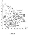
- the reason for using 450 nmcan be explained using the chromaticity diagram of FIG. 1 . Given three colors that can be located on the chromaticity diagram, it is only possible to create by addition colors which are on the interior of a triangle created by placing corner points at the three colors. It is clear from FIG. 1 that a wavelength of 450 nm is ideal. A display system based on a wavelength of 470 nm would create a situation where a number of well saturated purples and red-purples are outside the triangle and, thus, not accessible to the display system.
- Nd:YAG lasersoperating at 1064 nm.
- the output of the laseris frequency doubled with a nonlinear crystal to 532 nm.
- the frequency-doubled outputthen pumps an OPO.
- One of the OPO output wavelengthsis then summed with the 532-nm light to create the blue.
- Nd:YAG lasersrequire water-cooling and resonator structures, which add to the complexity, bulk and cost of the system.
- the apparatusgenerally comprises a light-generating fiber device optically coupled to an optical harmonic generator.
- the fiber deviceproduces radiation at a power level sufficient to operate the optical harmonic generator.
- the optical harmonic generatorincreases a frequency of the radiation to produce a blue output radiation.
- the fiber devicemay be an oscillator or an amplifier, such as a Neodymium-doped cladding-pumped fiber amplifier.
- the fiber devicemay be pumped by a high intensity pump source to enhance the gain of radiation having a harmonic that is blue.
- the pump powerpreferably remains above 50 Watts/mm 2 along substantially the entire length of the fiber.
- the power of pumping radiationis preferably greater than about 100 Watts/mm 2 and more preferably, about 500 Watts/mm 2 or greater at a fiber entrance depending on the pumping configuration.
- an oscillatormay be optionally coupled to the fiber amplifier.
- the oscillatorproduces source radiation.
- the fiber amplifieramplifies the radiation produced by the oscillator.
- Suitable oscillatorsinclude mode locked lasers based on transitions in Nd:Glass, Nd:Vanadate, Nd:YLF, and other Nd materials and pulsed semiconductor lasers.
- the fiber devicetypically produces infrared radiation having a frequency with a harmonic that falls in the blue portion of the visible spectrum.
- the optical harmonic generatorgenerates blue light from the infrared light, by a non-linear harmonic generation process.
- the fiber devicemay include means to suppress gain of radiation having harmonics that are not blue. Such means include dopants, fiber gratings, and dichroic mirrors. In a specific embodiment, the gain suppression means suppresses gain at 1.05 ⁇ m without suppressing gain at 0.91 ⁇ m.
- a first alternative means for optical gain suppressionincludes a fiber having a core surrounded by a cladding with a tunnel cladding disposed between the cladding and the core. Light of an undesired wavelength tunnels out of the core along the length of the fiber. The fiber thus has no bound modes at the undesired wavelength.
- a second alternative means for optical gain suppressionincludes a fiber that has been bent to a bend radius such that wavelength dependent losses caused by the bending attenuate radiation of the undesired wavelength.
- the fiber device and blue laser apparatusfind application as light sources for three-color light displays.
- Light sources based on the embodiments of the present inventionare capable of producing blue light at an output power of order 1 watt or more.
- FIG. 1depicts a chromaticity diagram, depicting color location
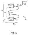
- FIG. 2Adepicts a simplified schematic diagram of a blue laser according to a first embodiment of the present invention
- FIG. 2Bdepicts cross sectional schematic diagram of a fiber used in the laser of FIG. 2A;
- FIG. 2Cdepicts a simplified schematic diagram of a blue laser according to an alternative embodiment of the present invention
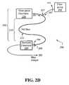
- FIG. 2Ddepicts a simplified schematic diagram of a blue laser according to an alternative embodiment of the present invention.
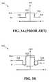
- FIG. 3 Adepicts a refractive index profile of a conventional fiber
- FIGS. 3B-3Cdepict refractive index profiles for rejecting undesired wavelengths from the core of a fiber according to an embodiment of the present invention
- FIG. 3Ddepicts a simplified schematic diagram of a blue laser having a refractive index profile of FIG. 3C;
- FIG. 4Adepicts attenuation versus bend wavelength for a coiled fiber
- FIG. 4Bdepicts an embodiment of a blue laser source incorporating a coiled fiber to suppress gain at an undesired wavelength
- FIG. 5depicts a simplified schematic diagram of a display system according to a fourth embodiment of the present invention.
- blue lightgenerally refers to electromagnetic radiation having a frequency of between about 6.7 ⁇ 10 14 Hz and 6.3 ⁇ 10 14 Hz (about 430 to 480 nm wavelength in vacuum).
- Green lightrefers to radiation having a frequency of between about 5.9 ⁇ 10 14 Hz and 5.5 ⁇ 10 14 Hz (about 510 to 550 nm wavelength in vacuum).
- Red lightrefers to radiation having a frequency of between about 4.8 ⁇ 10 14 Hz and 4.2 ⁇ 10 14 Hz (about 620 to 720 nm wavelength in vacuum).
- FIG. 2Adepicts a simplified schematic diagram of a blue laser apparatus according to a first embodiment of the present invention.
- the laser 200generally comprises a Neodymium-doped cladding-pumped light-generating fiber device 202 optically coupled to a harmonic generator 220 .
- the fiber device 202may include a fiber oscillator, a fiber amplifier or both.
- the harmonic generator 220generates a second or higher order harmonic of a source radiation 201 from the fiber device 202 .
- the generated second or higher order harmonic of the source radiation 201is characterized by a wavelength in vacuum corresponding to the color blue and referred to as blue output radiation 203 .
- the fiber device 202comprises a fiber amplifier 210 .
- the fiber amplifier 210receives optical power in the form of source radiation 201 from an oscillator 230 .
- the fiber amplifier 210amplifies the optical power from the oscillator 230 to a level on the order of 1 watt or greater.
- the harmonic generator 220may, for example, be a second-harmonic generator that doubles the frequency of the output of the amplifier 210 to produce blue output radiation 203 .
- the blue radiationis preferably characterized by a wavelength in vacuum of between about 440 nm and about 460 nm.
- harmonic generator 220may generate higher order harmonics of the source radiation 201 such as third-harmonics, etc. to produce blue radiation.
- the fiber amplifier 210generally comprises an optical fiber 212 having a core 214 made of Neodymium doped glass.
- FIG. 2Bdepicts cross sectional schematic diagrams of the optical fiber 212 .
- the fiber 212generally comprises the core 214 surrounded by a cladding 217 including inner and outer cladding layers 216 and 218 respectively.
- the cladding layer 216is optically coupled to a pump source 240 .
- the pump source 240may comprise one or more high-power pump diodes, for example, at a wavelength near 0.80 microns. Because of the three-level nature of the transition in Nd:Glass, the pump source 240 preferably produces pumping radiation 205 having an intensity that is a substantial fraction of a saturation intensity of the pumped transition, e.g. about 500 Watts/mm 2 .
- Such a pump source 240is generally referred to herein as a high-brightness pump source.
- core 214is preferably a single-mode core surrounding by a multi-mode inner cladding layer 216 which, turn, is surrounded by outer cladding layer 218 .
- the core 214is typically doped with Nwodymium (Nd).
- NdNwodymium
- a relatively high-power multimode pumping radiation signal 205 launched into the cladding 217 from the pump sourceis substantially confined and guided within the multi-mode cladding layer.
- Pumping radiation 205propagates along the multi-mode inner cladding layer 216 criss-crossing the core 214 .
- the Nd doped core 214absorbs energy from the pumping radiation 205 . The absorbed energy is converted into laser output radiation 208 within the core.
- Neodymium glassis known to have gain at a wavelength of 0.91 microns, but its gain at 1.05 microns is higher.
- Gain-suppression means at wavelengths having second harmonics that are not bluemay be necessary, to keep parasitic oscillation at these wavelengths from extracting all the power from the amplifier 210 .
- a first conditionis for fiber 212 to have a distributed loss means that attenuates the 1.05 micron radiation from the high gain, undesired, long-wavelength transition much more than they attenuate the radiation from the desired, short wavelength transition.
- a second conditionis that the intensity of the pumping radiation 205 at a wavelength near 800 nm be relatively high.
- the pump intensitypreferably remains above 50 Watts/mm 2 along substantially the entire length of the fiber.
- the power of pumping radiationis preferably about 500 Watts/mm 2 or greater at a fiber entrance 207 if the pump radiation 205 passes once through the fiber 212 .
- the minimum required pump intensitymay be reduced to about 250 Watts/mm 2 if the pump radiation 205 exiting at a far end 209 of the fiber 212 is retroreflected so that it returns to the fiber 212 .
- the intensity of pump radiation 205may also be reduced if, for example, identical pumps are used at both ends of the fiber 212 .
- the pump sources e.g. pump source 240produce sufficient pump power that pump radiation 205 has an intensity of 50 Watts/mm 2 or greater inside the fiber 212 and an intensity greater than or equal to 100 Watts/mm 2 at the entrance to the fiber 212 .
- Pumping intensities at levels greater than or equal to about 100 Watts/mm 2have only recently become available.
- One pump source commonly used for diode pumpingis an SDL-3460-P6 diode from SDL of San Jose, Calif. This pump source provides 16 Watts of power from a 0.6 mm diameter aperture. The pump intensity, i.e. the power divided by the aperture area is equal to about 57 Watts/mm 2 . This is generally inadequate for pumping the short wavelength transition of Nd:glass fiber, even with double ended pumping and suppression of the 1.05 micron transition.
- a newer design of fiber pumpis available from LIMO of Dortmund, Germany.
- This diode sourcehas a power of about 25 Watts from a 0.2 mm diameter fiber. The corresponding intensity is about 795 Watts/mm 2 . This is more than adequate to pump the short-wavelength transition of Nd:glass, even with single-ended pumping.
- the cladding 217may include dopants that absorb radiation emitted by a 4 F 3/2 to 4 I 11/2 atomic transition corresponding to a wavelength in vacuum of 1.05 microns for Neodymium glass and 1.06 microns for Nd:YAG.
- the dopantsare also transparent to radiation emitted by a 4 F 3/2 to 4 I 9/2 atomic transition corresponding to 0.91 microns in Neodymium glass and 0.946 microns in Nd:YAG.
- dopantsinclude ions such as Yb 3+ , Dy 3+ , Pr 3+ , Tm 2+ and Sm 3+ and V 3+ .
- gain at undesired wavelengthsmay be suppressed by means of gratings or mirrors.
- fiber 212may have an index of refraction n that varies periodically along its length to form gratings 250 .
- the gratingscan reflect certain wavelengths of light out of the fiber while transmitting others.
- maxima in nare typically separated by a distance of approximately one-half the wavelength of undesired light in the fiber.
- the gratingsare usually aligned at a non-normal incidence with respect to the fiber axis. Such gratings reject the undesired wavelengths from the core 214 of fiber 212 .
- Fiber 212may also include dichroic mirrors 260 coupled to the ends of the fibers.
- the mirrorstransmit wavelengths in an undesired range, e.g. 1.05 microns, while reflecting other wavelengths, e.g. 0.91 microns back into the fiber.
- FIGS. 3A-3CA first alternative method for suppressing undesired wavelengths is depicted in FIGS. 3A-3C.
- the alternative method for suppressing the undesired wavelengthis based on the observation that a typical fiber core surrounded by a cladding always has at least one bound mode at any wavelength.
- FIG. 3Adepicts a graph 300 of refractive index n versus radial distance r from the center of a typical optical fiber.
- the core region 302typically has a higher refractive index than the cladding region 304 . Total internal reflection takes place at the interface 306 between the core region 302 and the cladding region 304 .
- a fiberhas a core region 312 surrounded by a tunnel cladding region 313 .
- a cladding region 314surrounds the tunnel cladding 313 and core regions 312 .
- the coreis characterized by a refractive index n core and a radius r c .
- the cladding region 314is characterized by a refractive index n c1 and a thickness t c1 .
- the tunnel cladding region 313is characterized by a refractive index n′ and a thickness t′. Generally, n′ ⁇ n c1 ⁇ n core . Such a refractive index profile is sometimes referred to as a “W” profile.
- Wrefractive index profile
- the propagation of radiation in fibers having such profilesis described in detail by Michael Monerie in “Propagation in Doubly Clad Single-Mode Fibers”, IEEE Journal of Quantum Electronics QE-18 (1982) p. 525, which is incorporated herein by reference, and references therein.
- n core , n c1 , n′, r c , t c1 and t′are chosen such that an average squared index of refraction ⁇ n 2 (r)> ⁇ n c1 2 , then there exists a cutoff wavelength ⁇ c for which light having wavelengths (in vacuum) greater than ⁇ c will have no bound modes. Undesired wavelengths above ⁇ c will be scattered out of the fiber along its length while bound modes of desirable wavelengths below ⁇ c are retained in the fiber.
- the tunnel cladding region 313is thick enough that ⁇ n 2 (r)> ⁇ n c1 2 but thin enough to provide efficient tunneling of the undesired wavelengths.
- a specific embodiment of a practical application of this principleutilizes a triply clad fiber illustrated by the refractive index profile 320 of FIG. 3 C.
- the fibergenerally comprises, as shown in FIGS. 3C and 3D, a core region 322 surrounded by a tunnel cladding region 323 .
- a pump cladding region 324surrounds the core 322 and tunnel cladding 323 regions.
- An outer cladding region 326surrounds the core 322 , tunnel cladding 323 , and pump cladding 324 regions.
- the coreis characterized by a refractive index n core and a radius r c .
- the tunnel cladding region 323is characterized by a refractive index n′ and a thickness t′.
- the pump cladding region 324is characterized by a refractive index n pc and a thickness t pc .
- the outer claddingis characterized by an index of refraction n oc and a thickness t oc .
- the outer claddingmay be surrounded by air having an index of refraction of about 1.0.
- n′ ⁇ n pc ⁇ n core and n oc ⁇ n pcSuch a configuration allows the undesired radiation to tunnel out of the core region 322 .
- Total internal reflection at an interface 325 between the pump cladding 324 and outer cladding 326provides a bound mode that confines the pumping radiation for efficient pumping of the core region 322 .
- the radius r pcis typically greater than a few undesired wavelengths.
- FIG. 4Adepicts a graph 400 of attenuation versus wavelength ⁇ for a coiled fiber.
- attenuationis measured in dB.
- the attenuationrises abruptly as wavelength increases.
- the abrupt rise 402 in the attenuation curveeffectively divides the wavelength axis into a weakly attenuated region 404 and a strongly attenuated region 406 . It turns out that the location of the abrupt rise 402 and, hence, the boundary between the weakly and strongly attenuated regions depends on the bend radius of the coiled fiber.
- a coiled fibermay attenuate undesired long wavelengths but not desired shorter wavelengths.
- a coiled fibermay be engineered to attenuate 1050 nm (i.e. 1.05 micron) radiation but not 910 nm (i.e. 0.91 micron) radiation.
- FIG. 4Bdepicts an exemplary embodiment of a blue laser apparatus incorporating a coiled fiber to suppress optical gain at an undesired wavelength.
- the apparatusgenerally comprises a cladding-pumped fiber device 420 .
- the fiber device 420generally comprises an optical fiber 422 coiled around a mandrel of radius R.
- the radius of the mandrel 424determines a bend radius of the fiber 422 for suppression of gain at an undesired wavelength, e.g. 1050 nm, as described above.
- Ris typically of order 10 mm. Attenuation of radiation by bending optical fibers is discussed in detail by Sakai et al. in Applied Optics 17 (1978) p.
- a pump 410provides pump radiation for the fiber device 420 .
- the pump 410is optically coupled to a cladding of the fiber 422 to provide pumping as described above with respect to FIG. 2 B.
- An optional source 412provides radiation to a core of the fiber 422 .
- the fiber device 420may be coupled to a harmonic generator 430 to produce blue radiation, e.g., by doubling 910 nm infrared radiation.
- the harmonic generator 220typically comprises a non-linear crystal including a material such as Lithium Niobate (LiNbO 3 ), Lithium Tantalate (LiTaO 3 ), Lithium Borate (LiBO 3 ), Potassium Niobate, periodically poled lithium niobate (PPLN), periodically poled lithium tantalate (PPLT) MgO:PPLN, KTP, PPKTP, RTA, BBO, or PPRTA.
- the harmonic generator 220may be a second-harmonic generator that interacts with two photons of the source radiation 201 to produce a single photon of output radiation 203 .
- the output radiation 203will have a wavelength of 455 nm, which the eye senses as blue.
- a given piece of non-linear crystalhas a characteristic frequency-doubling coefficient in units of % per Watt of input power. Generally, the higher the input power, the higher the conversion efficiency.
- the power of output radiation 203goes as the square of the power of input source radiation 201 up to a point were the input is significantly depleted.
- the crystalline axes of the material comprising second-harmonic generator 220must be in the right orientation, the crystal must be at the right temperature, the crystal must not damage under high input power.
- non-linear crystalsmay also be used as third-harmonic generators to triple the frequency of source radiation 201 , or as higher order harmonic generators.
- the fiber device 202includes a fiber amplifier, such as fiber amplifier 210 and the amplifier is coupled to an oscillator, such as oscillator 230 .
- the oscillatormust provide source radiation 201 at the correct wavelength because the amplifier 210 generally does not shift wavelengths.
- the average power of the radiation in the amplifier 210is preferably on the order of 10 mW or greater so that the amplifier 210 operates stably and with low noise.
- the oscillatormust have a low enough duty cycle so that the peak power after amplification is high enough for efficient non-linear conversion in the harmonic generator 220 .
- the oscillator 230may be, for example, a short-pulse oscillator that produces infrared radiation at a wavelength near 0.91 microns for Neodymium-doped fiber amplifier 210 and a few milliwatts of power.
- Exemplary embodiments of oscillator 230include pulsed, low-duty-cycle semiconductor lasers and mode-locked Nd:Glass or crystal lasers. Low duty cycle, short pulse (e.g. ⁇ 100 ps) oscillators are typically used to provide sufficient peak power for existing harmonic generators.
- One oscillator typeis a mode-locked neodymium bulk crystalline or glass laser operating at the same transition as the Nd:Glass fiber 212 .
- Mode-locked laserscan conveniently have a ratio of peak power to average power of 1000. Thus an amplified signal with a 1 Watt average power would have a 1 kilowatt peak power, which is adequate for efficient nonlinear conversion.
- mode-locked lasershave been difficult to maintain and operate. The typically require complex electronics and tight mechanical tolerances.
- Such “passively mode-locked”typically use Nd:YLF, Nd:Yttrium Vanadate, or Nd:Glass.
- Such a “passively mode-locked” lasermay be used as oscillator 230 .
- Another possible type of device for oscillator 230is a modulated semiconductor laser.
- Semiconductor lasers with a wavelength of 910 nmare available. Some of these lasers can be electrically pulsed to provide pulses as short as 100 psec (10 ⁇ 10 sec), while maintaining an average power near 1 mW and peak power near 100 mW. Such a power level and duty cycle are approximately adequate for efficient conversion to blue light after amplification which would increase the average power to about 10 Watts and peak power to about 1 kW. Improvements in semiconductor laser technology may make this approach more competitive with mode-locked lasers.
- a semiconductor lasermay be externally modulated using, for example, a waveguide modulator.
- Waveguide modulatorsmay be faster than electrical pulsing of the semiconductor laser itself. Furthermore, waveguide modulators may provide better stability.
- a blue laser of the type described above with respect to FIGS. 2A and 2Bcan be incorporated into a three-color light source according to a second embodiment of the present invention.
- a blue laser sourceof the type described above with respect to FIGS. 2A and 2B can be incorporated into a three-color light source according to a second embodiment of the present invention.
- the following descriptiondescribes a specific embodiment that uses such a source to generate blue light, other blue laser sources may be used without loss of generality.
- FIG. 5depicts a simplified schematic diagram of a display system 500 according to a fourth embodiment of the present invention.
- the system 500generally comprises a three color source 502 , and a scanning means 506 optically coupled to the source 502 .
- the source 502produces blue laser light as described above.
- the source 502may produce green and red light by any suitable means.
- the source 502may alternatively produce other color combinations of three or more colors, including blue.
- the modulating means 504modulates the intensities of the red, green, and blue light to produce different colors.
- the light emerging from the source 502may be split into three separate beams, each beam corresponding to a different color, through the use of-wavelength selective beam splitters.
- the generation of different colors by mixing of three or more primary colorsis well known in the art.
- Each of the three beamsmay be separately modulated and then recombined to form an output beam 508 .
- the scanner 506produces an image 510 from the modulated output beam 508 .
- the scannermay be coupled to the source 502 or the modulator 504 .
- the scannermay raster scan the output beam 508 across a screen 512 in two dimensions in a manner having features in common with conventional video image generation.
- the modulator 504modulates the power of a beam of output radiation
- a hi-speed scanning systemrasters the beam across a screen.
- the scanner 506may produce an image line-by-line.
- a line-by-line systemcreates a whole “line” of the display at a time, by spreading the light over a linear array of modulators. This line is then scanned across the screen 512 in only one dimension.
- Embodiments of the present invention that utilize fiber amplifierscan be much more efficient than competing techniques, since fiber amplifiers are very efficient. Temperature of pump diodes can be less critical since fiber amplifiers have loose tolerances on pump wavelength. The embodiments of the present invention can be implemented without water cooling since the more efficient system dissipates less heat and the tolerant pump wavelength specification generally requires less precise temperature control. Furthermore, fiber based systems can be made more compact since fiber can be wound up into a small volume.
Landscapes
- Physics & Mathematics (AREA)
- Electromagnetism (AREA)
- Optics & Photonics (AREA)
- Engineering & Computer Science (AREA)
- Plasma & Fusion (AREA)
- Condensed Matter Physics & Semiconductors (AREA)
- General Physics & Mathematics (AREA)
- Lasers (AREA)
- Laser Surgery Devices (AREA)
- Optical Modulation, Optical Deflection, Nonlinear Optics, Optical Demodulation, Optical Logic Elements (AREA)
Abstract
Description

Claims (14)
Priority Applications (8)
| Application Number | Priority Date | Filing Date | Title |
|---|---|---|---|
| US09/608,442US6614815B1 (en) | 2000-06-29 | 2000-06-29 | Blue laser based on interactions in fiber |
| JP2002507484AJP4180364B2 (en) | 2000-06-29 | 2001-06-12 | Blue laser based on interaction in fiber |
| DE60126098TDE60126098T2 (en) | 2000-06-29 | 2001-06-12 | BLUE LASER BASED ON INTERACTIONS IN A FIBER |
| KR1020027017688AKR100813354B1 (en) | 2000-06-29 | 2001-06-12 | Blue laser based action on optical fiber |
| AT01944485TATE352114T1 (en) | 2000-06-29 | 2001-06-12 | BLUE LASER BASED ON INTERACTIONS IN A FIBER |
| EP01944485AEP1307953B1 (en) | 2000-06-29 | 2001-06-12 | Blue laser based on interactions in fiber |
| CN018120121ACN1218447C (en) | 2000-06-29 | 2001-06-12 | Blue laser based on interactions in fiber |
| PCT/US2001/018987WO2002003513A1 (en) | 2000-06-29 | 2001-06-12 | Blue laser based on interactions in fiber |
Applications Claiming Priority (1)
| Application Number | Priority Date | Filing Date | Title |
|---|---|---|---|
| US09/608,442US6614815B1 (en) | 2000-06-29 | 2000-06-29 | Blue laser based on interactions in fiber |
Publications (1)
| Publication Number | Publication Date |
|---|---|
| US6614815B1true US6614815B1 (en) | 2003-09-02 |
Family
ID=24436523
Family Applications (1)
| Application Number | Title | Priority Date | Filing Date |
|---|---|---|---|
| US09/608,442Expired - LifetimeUS6614815B1 (en) | 2000-06-29 | 2000-06-29 | Blue laser based on interactions in fiber |
Country Status (8)
| Country | Link |
|---|---|
| US (1) | US6614815B1 (en) |
| EP (1) | EP1307953B1 (en) |
| JP (1) | JP4180364B2 (en) |
| KR (1) | KR100813354B1 (en) |
| CN (1) | CN1218447C (en) |
| AT (1) | ATE352114T1 (en) |
| DE (1) | DE60126098T2 (en) |
| WO (1) | WO2002003513A1 (en) |
Cited By (12)
| Publication number | Priority date | Publication date | Assignee | Title |
|---|---|---|---|---|
| US20020003569A1 (en)* | 2000-07-07 | 2002-01-10 | Bernard Beier | Forming an image on a printing plate using ultrashort laser pulses |
| US20040052278A1 (en)* | 2001-08-10 | 2004-03-18 | Lightwave Electronics Corporation | Fiber amplifier system for producing visible light |
| US20050041702A1 (en)* | 1997-03-21 | 2005-02-24 | Imra America, Inc. | High energy optical fiber amplifier for picosecond-nanosecond pulses for advanced material processing applications |
| US20050058163A1 (en)* | 2003-09-12 | 2005-03-17 | Lightwave Electronics Corporation | High repetition rate passively Q-switched laser for blue laser based on interactions in fiber |
| US20060002434A1 (en)* | 2004-07-01 | 2006-01-05 | Toyoda Koki Kabushiki Kaisha | Fiber laser oscillators |
| US20070110379A1 (en)* | 2005-11-14 | 2007-05-17 | Applied Materials, Inc. Legal Department | Pinch waveguide |
| US20080036921A1 (en)* | 2004-11-08 | 2008-02-14 | Toshifumi Yokoyama | Video Projector Using Coherent Light Source |
| US20080075130A1 (en)* | 2004-07-15 | 2008-03-27 | Kiminori Mizuuchi | Coherent Light Source and Optical Device Using the Same |
| WO2007059129A3 (en)* | 2005-11-14 | 2009-04-30 | Applied Materials Inc | Pinch waveguide |
| CN104362497A (en)* | 2014-11-20 | 2015-02-18 | 山东海富光子科技股份有限公司 | Single-frequency blue-green light source based on 930 nm single-frequency fiber laser unit |
| US9716365B2 (en) | 2013-03-22 | 2017-07-25 | Ipg Photonics Corporation | High power neodymium fiber lasers and amplifiers |
| CN110678790A (en)* | 2017-06-02 | 2020-01-10 | 康普技术有限责任公司 | Concentric fiber for space division multiplexing optical communication and method of use |
Families Citing this family (6)
| Publication number | Priority date | Publication date | Assignee | Title |
|---|---|---|---|---|
| RU2254649C2 (en)* | 2003-07-30 | 2005-06-20 | Корнев Алексей Федорович | Laser projector and device for shaping laser beam of visible-spectrum blue region for laser projector |
| EP2625753B1 (en)* | 2010-10-07 | 2019-11-20 | IPG Photonics Corporation | High power neodymium fiber lasers and amplifiers |
| CN107621672A (en)* | 2016-07-14 | 2018-01-23 | 中国兵器装备研究院 | A kind of integrated high power cladding light stripper |
| DE102017109954B3 (en)* | 2017-05-09 | 2018-05-24 | Active Fiber Systems Gmbh | Short pulse laser with high temporal contrast |
| CN111596408B (en)* | 2020-05-25 | 2022-01-25 | 光惠(上海)激光科技有限公司 | High-power fiber laser indication light protection device and implementation method thereof |
| CN111711061A (en)* | 2020-06-29 | 2020-09-25 | 华南理工大学 | Dual-wavelength all-fiber laser |
Citations (22)
| Publication number | Priority date | Publication date | Assignee | Title |
|---|---|---|---|---|
| US4764933A (en)* | 1986-08-15 | 1988-08-16 | Stanford University | Diode pumped low doped Nd 3+ glass laser |
| US5056888A (en) | 1989-07-17 | 1991-10-15 | Minnesota Mining And Manufacturing Company | Single-mode, single-polarization optical fiber |
| US5388113A (en) | 1993-01-27 | 1995-02-07 | Sony Corporation | Laser generating apparatus |
| US5651019A (en) | 1995-04-28 | 1997-07-22 | The United States Of America As Represented By The Secretary Of The Navy | Solid-state blue laser source |
| US5659558A (en) | 1995-03-06 | 1997-08-19 | Matsushita Electric Industrial Co., Ltd. | Short-wavelength laser element doped with rare earth ions, optical amplifier doped with rare earth ions, and wavelength converter doped with rare earth ions |
| US5745284A (en) | 1996-02-23 | 1998-04-28 | President And Fellows Of Harvard College | Solid-state laser source of tunable narrow-bandwidth ultraviolet radiation |
| US5774484A (en) | 1994-01-28 | 1998-06-30 | British Telecommunications Plc | Two-stage mono-mode optical fibre laser |
| US5818630A (en)* | 1997-06-25 | 1998-10-06 | Imra America, Inc. | Single-mode amplifiers and compressors based on multi-mode fibers |
| US5867305A (en) | 1996-01-19 | 1999-02-02 | Sdl, Inc. | Optical amplifier with high energy levels systems providing high peak powers |
| US5880877A (en)* | 1997-01-28 | 1999-03-09 | Imra America, Inc. | Apparatus and method for the generation of high-power femtosecond pulses from a fiber amplifier |
| US5892615A (en) | 1997-03-17 | 1999-04-06 | Sdl, Inc. | Output power enhancement in optical fiber lasers |
| US5909306A (en) | 1996-02-23 | 1999-06-01 | President And Fellows Of Harvard College | Solid-state spectrally-pure linearly-polarized pulsed fiber amplifier laser system useful for ultraviolet radiation generation |
| US5912910A (en) | 1996-05-17 | 1999-06-15 | Sdl, Inc. | High power pumped mid-IR wavelength systems using nonlinear frequency mixing (NFM) devices |
| US5966391A (en) | 1997-06-27 | 1999-10-12 | Mcdonnell Douglas Corporation | Long cavity laser system including frequency doubling long cavity fiber optic laser system |
| US5974059A (en) | 1997-03-04 | 1999-10-26 | 3M Innovative Properties Company | Frequency doubled fiber laser |
| US5999548A (en)* | 1997-06-18 | 1999-12-07 | Nippon Telegraph And Telephone Corporation | White optical pulse source and applications |
| US6009114A (en) | 1991-01-14 | 1999-12-28 | Light Age Inc. | Method and apparatus for pumping of transition metal ion containing solid state lasers using diode laser sources |
| US6021141A (en)* | 1996-03-29 | 2000-02-01 | Sdl, Inc. | Tunable blue laser diode |
| US6154321A (en)* | 1998-01-20 | 2000-11-28 | University Of Washington | Virtual retinal display with eye tracking |
| US6212310B1 (en)* | 1996-10-22 | 2001-04-03 | Sdl, Inc. | High power fiber gain media system achieved through power scaling via multiplexing |
| US6278816B1 (en)* | 1997-12-09 | 2001-08-21 | Scientific-Atlanta, Inc. | Noise reduction technique for cladding pumped optical amplifiers |
| US6307994B1 (en)* | 1998-06-24 | 2001-10-23 | Samsung Electronics Co., Ltd. | Multi-cladding optical fiber, long-period optical fiber grating written therein and writing method thereof |
Family Cites Families (1)
| Publication number | Priority date | Publication date | Assignee | Title |
|---|---|---|---|---|
| US6362916B2 (en)* | 1998-09-25 | 2002-03-26 | Fiver Laboratories | All fiber gain flattening optical filter |
- 2000
- 2000-06-29USUS09/608,442patent/US6614815B1/ennot_activeExpired - Lifetime
- 2001
- 2001-06-12JPJP2002507484Apatent/JP4180364B2/ennot_activeExpired - Lifetime
- 2001-06-12DEDE60126098Tpatent/DE60126098T2/ennot_activeExpired - Fee Related
- 2001-06-12KRKR1020027017688Apatent/KR100813354B1/ennot_activeExpired - Fee Related
- 2001-06-12ATAT01944485Tpatent/ATE352114T1/ennot_activeIP Right Cessation
- 2001-06-12WOPCT/US2001/018987patent/WO2002003513A1/enactiveIP Right Grant
- 2001-06-12CNCN018120121Apatent/CN1218447C/ennot_activeExpired - Fee Related
- 2001-06-12EPEP01944485Apatent/EP1307953B1/ennot_activeExpired - Lifetime
Patent Citations (26)
| Publication number | Priority date | Publication date | Assignee | Title |
|---|---|---|---|---|
| US4764933A (en)* | 1986-08-15 | 1988-08-16 | Stanford University | Diode pumped low doped Nd 3+ glass laser |
| US5056888A (en) | 1989-07-17 | 1991-10-15 | Minnesota Mining And Manufacturing Company | Single-mode, single-polarization optical fiber |
| US6009114A (en) | 1991-01-14 | 1999-12-28 | Light Age Inc. | Method and apparatus for pumping of transition metal ion containing solid state lasers using diode laser sources |
| US5388113A (en) | 1993-01-27 | 1995-02-07 | Sony Corporation | Laser generating apparatus |
| US5774484A (en) | 1994-01-28 | 1998-06-30 | British Telecommunications Plc | Two-stage mono-mode optical fibre laser |
| US5659558A (en) | 1995-03-06 | 1997-08-19 | Matsushita Electric Industrial Co., Ltd. | Short-wavelength laser element doped with rare earth ions, optical amplifier doped with rare earth ions, and wavelength converter doped with rare earth ions |
| US5651019A (en) | 1995-04-28 | 1997-07-22 | The United States Of America As Represented By The Secretary Of The Navy | Solid-state blue laser source |
| US5867305A (en) | 1996-01-19 | 1999-02-02 | Sdl, Inc. | Optical amplifier with high energy levels systems providing high peak powers |
| US5930030A (en) | 1996-01-19 | 1999-07-27 | Sdl, Inc. | Apparatus for pumping an optical gain medium with multiple light wavelengths |
| US5933271A (en) | 1996-01-19 | 1999-08-03 | Sdl, Inc. | Optical amplifiers providing high peak powers with high energy levels |
| US5909306A (en) | 1996-02-23 | 1999-06-01 | President And Fellows Of Harvard College | Solid-state spectrally-pure linearly-polarized pulsed fiber amplifier laser system useful for ultraviolet radiation generation |
| US5745284A (en) | 1996-02-23 | 1998-04-28 | President And Fellows Of Harvard College | Solid-state laser source of tunable narrow-bandwidth ultraviolet radiation |
| US6021141A (en)* | 1996-03-29 | 2000-02-01 | Sdl, Inc. | Tunable blue laser diode |
| US6301271B1 (en)* | 1996-05-17 | 2001-10-09 | Sdl, Inc. | Frequency conversion system |
| US5912910A (en) | 1996-05-17 | 1999-06-15 | Sdl, Inc. | High power pumped mid-IR wavelength systems using nonlinear frequency mixing (NFM) devices |
| US6212310B1 (en)* | 1996-10-22 | 2001-04-03 | Sdl, Inc. | High power fiber gain media system achieved through power scaling via multiplexing |
| US5880877A (en)* | 1997-01-28 | 1999-03-09 | Imra America, Inc. | Apparatus and method for the generation of high-power femtosecond pulses from a fiber amplifier |
| US5974059A (en) | 1997-03-04 | 1999-10-26 | 3M Innovative Properties Company | Frequency doubled fiber laser |
| US5892615A (en) | 1997-03-17 | 1999-04-06 | Sdl, Inc. | Output power enhancement in optical fiber lasers |
| US6181465B1 (en)* | 1997-03-17 | 2001-01-30 | Sdl, Inc. | Optical fiber gain medium with wavelength selective core filter |
| US5999548A (en)* | 1997-06-18 | 1999-12-07 | Nippon Telegraph And Telephone Corporation | White optical pulse source and applications |
| US5818630A (en)* | 1997-06-25 | 1998-10-06 | Imra America, Inc. | Single-mode amplifiers and compressors based on multi-mode fibers |
| US5966391A (en) | 1997-06-27 | 1999-10-12 | Mcdonnell Douglas Corporation | Long cavity laser system including frequency doubling long cavity fiber optic laser system |
| US6278816B1 (en)* | 1997-12-09 | 2001-08-21 | Scientific-Atlanta, Inc. | Noise reduction technique for cladding pumped optical amplifiers |
| US6154321A (en)* | 1998-01-20 | 2000-11-28 | University Of Washington | Virtual retinal display with eye tracking |
| US6307994B1 (en)* | 1998-06-24 | 2001-10-23 | Samsung Electronics Co., Ltd. | Multi-cladding optical fiber, long-period optical fiber grating written therein and writing method thereof |
Non-Patent Citations (3)
| Title |
|---|
| "Bend behavior of polarising optical fibers", Electronics Letters, Aug. 18, 1983, vol. 19, No.17, 679. |
| "Bending loss of propagation modes in arbitrary-index profile optical fibers", Jun-Ichi Sakai and Tatsuya Kimura, May 15, 1978/vol. 17, No. 10/Applied Optics, 1499. |
| "Propagation in doubly clad single-mode fibers", IEEE Journal of Quantum Electronics, vol. QE-18, No. 4, Apr. 1982, 535. |
Cited By (20)
| Publication number | Priority date | Publication date | Assignee | Title |
|---|---|---|---|---|
| US20050041702A1 (en)* | 1997-03-21 | 2005-02-24 | Imra America, Inc. | High energy optical fiber amplifier for picosecond-nanosecond pulses for advanced material processing applications |
| US20020003569A1 (en)* | 2000-07-07 | 2002-01-10 | Bernard Beier | Forming an image on a printing plate using ultrashort laser pulses |
| US6762787B2 (en)* | 2000-07-07 | 2004-07-13 | Heidelberger Druckmaschinen Ag | Forming an image on a printing plate using ultrashort laser pulses |
| US20040052278A1 (en)* | 2001-08-10 | 2004-03-18 | Lightwave Electronics Corporation | Fiber amplifier system for producing visible light |
| US7039076B2 (en) | 2001-08-10 | 2006-05-02 | Jds Uniphase Corporation | Fiber amplifier system for producing visible light |
| US20050058163A1 (en)* | 2003-09-12 | 2005-03-17 | Lightwave Electronics Corporation | High repetition rate passively Q-switched laser for blue laser based on interactions in fiber |
| US7116687B2 (en) | 2003-09-12 | 2006-10-03 | Jds Uniphase Corporation | High repetition rate passively Q-switched laser for blue laser based on interactions in fiber |
| US20060002434A1 (en)* | 2004-07-01 | 2006-01-05 | Toyoda Koki Kabushiki Kaisha | Fiber laser oscillators |
| US7457327B2 (en)* | 2004-07-01 | 2008-11-25 | Jtekt Corporation | Fiber laser oscillators |
| US20080075130A1 (en)* | 2004-07-15 | 2008-03-27 | Kiminori Mizuuchi | Coherent Light Source and Optical Device Using the Same |
| US20080036921A1 (en)* | 2004-11-08 | 2008-02-14 | Toshifumi Yokoyama | Video Projector Using Coherent Light Source |
| US7866822B2 (en)* | 2004-11-08 | 2011-01-11 | Panasonic Corporation | Video projector using coherent light source |
| US20070110379A1 (en)* | 2005-11-14 | 2007-05-17 | Applied Materials, Inc. Legal Department | Pinch waveguide |
| WO2007059129A3 (en)* | 2005-11-14 | 2009-04-30 | Applied Materials Inc | Pinch waveguide |
| US9716365B2 (en) | 2013-03-22 | 2017-07-25 | Ipg Photonics Corporation | High power neodymium fiber lasers and amplifiers |
| CN104362497A (en)* | 2014-11-20 | 2015-02-18 | 山东海富光子科技股份有限公司 | Single-frequency blue-green light source based on 930 nm single-frequency fiber laser unit |
| CN110678790A (en)* | 2017-06-02 | 2020-01-10 | 康普技术有限责任公司 | Concentric fiber for space division multiplexing optical communication and method of use |
| US10567080B2 (en)* | 2017-06-02 | 2020-02-18 | Commscope Technologies Llc | Concentric fiber for space-division multiplexed optical communications and method of use |
| US10784961B2 (en) | 2017-06-02 | 2020-09-22 | Commscope Technologies Llc | Concentric fiber for space-division multiplexed optical communications and method of use |
| CN110678790B (en)* | 2017-06-02 | 2021-01-26 | 康普技术有限责任公司 | Concentric fiber for space division multiplexing optical communication and method of use |
Also Published As
| Publication number | Publication date |
|---|---|
| CN1451195A (en) | 2003-10-22 |
| DE60126098D1 (en) | 2007-03-08 |
| WO2002003513A8 (en) | 2002-03-21 |
| CN1218447C (en) | 2005-09-07 |
| EP1307953B1 (en) | 2007-01-17 |
| EP1307953A4 (en) | 2005-04-13 |
| JP2004503098A (en) | 2004-01-29 |
| EP1307953A1 (en) | 2003-05-07 |
| DE60126098T2 (en) | 2007-06-21 |
| JP4180364B2 (en) | 2008-11-12 |
| ATE352114T1 (en) | 2007-02-15 |
| KR100813354B1 (en) | 2008-03-12 |
| WO2002003513A1 (en) | 2002-01-10 |
| KR20030095956A (en) | 2003-12-24 |
Similar Documents
| Publication | Publication Date | Title |
|---|---|---|
| US6614815B1 (en) | Blue laser based on interactions in fiber | |
| US7039076B2 (en) | Fiber amplifier system for producing visible light | |
| US6701044B2 (en) | Solid state laser generating UV radiation for writing fiber bragg gratings | |
| US7949017B2 (en) | Method and apparatus for generating high power visible and near-visible laser light | |
| US9153929B2 (en) | Mode-locked multi-mode fiber laser pulse source | |
| CN100432821C (en) | Coherent light source and optical device using the same | |
| US7965916B2 (en) | Laser light source device, image display and illuminator | |
| JP2014515175A (en) | Compact, coherent and bright light source for mid-infrared and far-infrared | |
| EP0744089A1 (en) | Passively q-switched picosecond microlaser | |
| US9667021B2 (en) | Phosphate photonic crystal fiber and converter for efficient blue generation | |
| US7733926B2 (en) | Thulium laser pumped Mid-IR source with broadbanded output | |
| CN106229803A (en) | A kind of optical fiber base single-frequency blue light pulse laser | |
| US7116687B2 (en) | High repetition rate passively Q-switched laser for blue laser based on interactions in fiber | |
| US20030031215A1 (en) | Compound light source employing passive Q-switching and nonlinear frequency conversion | |
| US7362783B2 (en) | Optical frequency mixing | |
| US6404785B1 (en) | Solid state modulated ultraviolet laser | |
| US20230124281A1 (en) | Apparatus and method for adjusting the wavelength of light | |
| JP3091329B2 (en) | Solid laser equipment | |
| JP2003133620A (en) | Broad band optical amplifier | |
| WO2025213548A1 (en) | Dual-wavelength femtosecond fiber laser | |
| CN117856008A (en) | Compact ultrashort pulse spectrum control device | |
| Limpert et al. | High power picosecond amplification in a low-nonlinearity single-mode photonic crystal fiber | |
| Yang et al. | Low threshold, dual-cavity continuous-wave fiber optical parametric oscillator |
Legal Events
| Date | Code | Title | Description |
|---|---|---|---|
| AS | Assignment | Owner name:LIGHTWAVE ELECTRONICS, CALIFORNIA Free format text:ASSIGNMENT OF ASSIGNORS INTEREST;ASSIGNORS:KANE, THOMAS J.;KEATON, GREGORY L.;REEL/FRAME:010903/0125 Effective date:20000629 | |
| STCF | Information on status: patent grant | Free format text:PATENTED CASE | |
| FEPP | Fee payment procedure | Free format text:PAT HOLDER NO LONGER CLAIMS SMALL ENTITY STATUS, ENTITY STATUS SET TO UNDISCOUNTED (ORIGINAL EVENT CODE: STOL); ENTITY STATUS OF PATENT OWNER: LARGE ENTITY | |
| AS | Assignment | Owner name:JDS UNIPHASE CORPORATION, CALIFORNIA Free format text:ASSIGNMENT OF ASSIGNORS INTEREST;ASSIGNOR:LIGHTWAVE ELECTRONICS CORPORATION;REEL/FRAME:016345/0054 Effective date:20050729 | |
| FPAY | Fee payment | Year of fee payment:4 | |
| FPAY | Fee payment | Year of fee payment:8 | |
| FPAY | Fee payment | Year of fee payment:12 | |
| AS | Assignment | Owner name:LUMENTUM OPERATIONS LLC, CALIFORNIA Free format text:ASSIGNMENT OF ASSIGNORS INTEREST;ASSIGNOR:JDS UNIPHASE CORPORATION;REEL/FRAME:036420/0340 Effective date:20150731 | |
| FEPP | Fee payment procedure | Free format text:PAYER NUMBER DE-ASSIGNED (ORIGINAL EVENT CODE: RMPN); ENTITY STATUS OF PATENT OWNER: LARGE ENTITY Free format text:PAYOR NUMBER ASSIGNED (ORIGINAL EVENT CODE: ASPN); ENTITY STATUS OF PATENT OWNER: LARGE ENTITY | |
| AS | Assignment | Owner name:LUMENTUM OPERATIONS LLC, CALIFORNIA Free format text:CORRECTIVE ASSIGNMENT TO CORRECT THE PATENTS LISTED ON PAGE A-A33 PREVIOUSLY RECORDED ON REEL 036420 FRAME 0340. ASSIGNOR(S) HEREBY CONFIRMS THE PATENT NUMBERS 7,868,247 AND 6,476,312 WERE LISTED IN ERROR AND SHOULD BE REMOVED;ASSIGNOR:JDS UNIPHASE CORPORATION;REEL/FRAME:037562/0513 Effective date:20150731 Owner name:LUMENTUM OPERATIONS LLC, CALIFORNIA Free format text:CORRECTIVE ASSIGNMENT TO CORRECT INCORRECT PATENTS 7,868,247 AND 6,476,312 ON PAGE A-A33 PREVIOUSLY RECORDED ON REEL 036420 FRAME 0340. ASSIGNOR(S) HEREBY CONFIRMS THE ASSIGNMENT;ASSIGNOR:JDS UNIPHASE CORPORATION;REEL/FRAME:037562/0513 Effective date:20150731 | |
| AS | Assignment | Owner name:LUMENTUM OPERATIONS LLC, CALIFORNIA Free format text:CORRECTIVE ASSIGNMENT TO CORRECT THE PATENTS LISTED ON PAGE A-A33 PATENT NUMBERS 7,868,247 AND 6,476,312 WERE LISTED IN ERROR AND SHOULD BE REMOVED. PREVIOUSLY RECORDED ON REEL 036420 FRAME 0340. ASSIGNOR(S) HEREBY CONFIRMS THE ASSIGNMENT;ASSIGNOR:JDS UNIPHASE CORPORATION;REEL/FRAME:037627/0641 Effective date:20150731 Owner name:LUMENTUM OPERATIONS LLC, CALIFORNIA Free format text:CORRECTIVE ASSIGNMENT TO CORRECT PATENTS 7,868,247 AND 6,476,312 LISTED ON PAGE A-A33 PREVIOUSLY RECORDED ON REEL 036420 FRAME 0340. ASSIGNOR(S) HEREBY CONFIRMS THE ASSIGNMENT;ASSIGNOR:JDS UNIPHASE CORPORATION;REEL/FRAME:037627/0641 Effective date:20150731 | |
| FEPP | Fee payment procedure | Free format text:PAYER NUMBER DE-ASSIGNED (ORIGINAL EVENT CODE: RMPN); ENTITY STATUS OF PATENT OWNER: LARGE ENTITY Free format text:PAYOR NUMBER ASSIGNED (ORIGINAL EVENT CODE: ASPN); ENTITY STATUS OF PATENT OWNER: LARGE ENTITY | |
| AS | Assignment | Owner name:DEUTSCHE BANK AG NEW YORK BRANCH, AS COLLATERAL AGENT, NEW YORK Free format text:PATENT SECURITY AGREEMENT;ASSIGNORS:LUMENTUM OPERATIONS LLC;OCLARO FIBER OPTICS, INC.;OCLARO, INC.;REEL/FRAME:047788/0511 Effective date:20181210 Owner name:DEUTSCHE BANK AG NEW YORK BRANCH, AS COLLATERAL AG Free format text:PATENT SECURITY AGREEMENT;ASSIGNORS:LUMENTUM OPERATIONS LLC;OCLARO FIBER OPTICS, INC.;OCLARO, INC.;REEL/FRAME:047788/0511 Effective date:20181210 | |
| AS | Assignment | Owner name:LUMENTUM OPERATIONS LLC, CALIFORNIA Free format text:RELEASE BY SECURED PARTY;ASSIGNOR:DEUTSCHE AG NEW YORK BRANCH;REEL/FRAME:051287/0556 Effective date:20191212 Owner name:OCLARO FIBER OPTICS, INC., CALIFORNIA Free format text:RELEASE BY SECURED PARTY;ASSIGNOR:DEUTSCHE AG NEW YORK BRANCH;REEL/FRAME:051287/0556 Effective date:20191212 Owner name:OCLARO, INC., CALIFORNIA Free format text:RELEASE BY SECURED PARTY;ASSIGNOR:DEUTSCHE AG NEW YORK BRANCH;REEL/FRAME:051287/0556 Effective date:20191212 |