US6614618B1 - Disk drive with feed-forward control path that receives a reference position signal to apply a feed-forward command effort at a rate greater than a servo sampling rate - Google Patents
Disk drive with feed-forward control path that receives a reference position signal to apply a feed-forward command effort at a rate greater than a servo sampling rateDownload PDFInfo
- Publication number
- US6614618B1 US6614618B1US09/538,931US53893100AUS6614618B1US 6614618 B1US6614618 B1US 6614618B1US 53893100 AUS53893100 AUS 53893100AUS 6614618 B1US6614618 B1US 6614618B1
- Authority
- US
- United States
- Prior art keywords
- feed
- servo
- signal
- rate
- disk drive
- Prior art date
- Legal status (The legal status is an assumption and is not a legal conclusion. Google has not performed a legal analysis and makes no representation as to the accuracy of the status listed.)
- Expired - Lifetime
Links
- 238000005070samplingMethods0.000titleclaimsabstractdescription42
- 238000012937correctionMethods0.000claimsabstractdescription3
- 230000004044responseEffects0.000claimsdescription8
- 230000008859changeEffects0.000claimsdescription4
- 230000005284excitationEffects0.000claims1
- 230000006870functionEffects0.000description8
- 230000001133accelerationEffects0.000description7
- 238000010586diagramMethods0.000description5
- 238000012546transferMethods0.000description5
- 230000005534acoustic noiseEffects0.000description3
- 230000003466anti-cipated effectEffects0.000description1
- 230000008901benefitEffects0.000description1
- 230000000295complement effectEffects0.000description1
- 238000011161developmentMethods0.000description1
- 230000001939inductive effectEffects0.000description1
- 238000000034methodMethods0.000description1
- 230000004048modificationEffects0.000description1
- 238000012986modificationMethods0.000description1
- 230000008569processEffects0.000description1
- 230000009467reductionEffects0.000description1
- 238000007493shaping processMethods0.000description1
Images


Classifications
- G—PHYSICS
- G11—INFORMATION STORAGE
- G11B—INFORMATION STORAGE BASED ON RELATIVE MOVEMENT BETWEEN RECORD CARRIER AND TRANSDUCER
- G11B5/00—Recording by magnetisation or demagnetisation of a record carrier; Reproducing by magnetic means; Record carriers therefor
- G11B5/48—Disposition or mounting of heads or head supports relative to record carriers ; arrangements of heads, e.g. for scanning the record carrier to increase the relative speed
- G11B5/58—Disposition or mounting of heads or head supports relative to record carriers ; arrangements of heads, e.g. for scanning the record carrier to increase the relative speed with provision for moving the head for the purpose of maintaining alignment of the head relative to the record carrier during transducing operation, e.g. to compensate for surface irregularities of the latter or for track following
- G11B5/596—Disposition or mounting of heads or head supports relative to record carriers ; arrangements of heads, e.g. for scanning the record carrier to increase the relative speed with provision for moving the head for the purpose of maintaining alignment of the head relative to the record carrier during transducing operation, e.g. to compensate for surface irregularities of the latter or for track following for track following on disks
- G11B5/59633—Servo formatting
- G—PHYSICS
- G11—INFORMATION STORAGE
- G11B—INFORMATION STORAGE BASED ON RELATIVE MOVEMENT BETWEEN RECORD CARRIER AND TRANSDUCER
- G11B5/00—Recording by magnetisation or demagnetisation of a record carrier; Reproducing by magnetic means; Record carriers therefor
- G11B5/48—Disposition or mounting of heads or head supports relative to record carriers ; arrangements of heads, e.g. for scanning the record carrier to increase the relative speed
- G11B5/54—Disposition or mounting of heads or head supports relative to record carriers ; arrangements of heads, e.g. for scanning the record carrier to increase the relative speed with provision for moving the head into or out of its operative position or across tracks
- G11B5/55—Track change, selection or acquisition by displacement of the head
- G11B5/5521—Track change, selection or acquisition by displacement of the head across disk tracks
Definitions
- the inventionrelates generally to magnetic disk drives and, more particularly, to a disk drive with a sampled servo control system with a feed-forward control path that outputs a feed-forward control.
- the resultis a closer approximation to a desired seek profile that provides a quieter faster seek over short to medium seek lengths.
- Magnetic disk drivesgenerally read and write data on the surface of a rotating magnetic disk with a transducer that is located at the far end of a moveable actuator.
- a servo control systemuses servo control information recorded amongst the data, or on a separate disk, to controllably move the actuator from track to track (“seeking”) and to hold the actuator at a desired position (“track following”).
- seekingtrack to track
- track followingtrack following
- a detailed discussion of servo control systemsis unnecessary because such systems are well known as set forth, for example, in patent application Ser. No. 09/138,841 now U.S. Pat. No. 6,204,988 that was filed on Aug. 24, 1998, entitled “DISK DRIVE CAPABLE OF AUTONOMOUSLY EVALUATING AND ADAPTING THE FREQUENCY RESPONSE OF ITS SERVO CONTROL SYSTEM,” and is commonly owned by the assignee of this application.
- Disk driveshave previously been used for storing conventional data files of the type that are associated with personal computers. In such applications, data integrity is paramount relative to other considerations such as seek times and the reduction of acoustic noise.
- Disk drivesare becoming popular for recording and replaying audiovisual data—e.g. a drive based recording device that replaces a video cassette recorder (VCR).
- VCRvideo cassette recorder
- a drive-based recording device of this naturewill benefit from using a disk drive with faster seek times because it will spend less time moving its actuator where it needs to be and more time recording or recovering information such that it may be able to record and/or playback more audiovisual data streams than otherwise possible.
- a drive-based recording deviceis likely to be located adjacent to a television or be in some other location where acoustic noise is undesirable. Accordingly, it is equally important for the disk drive to implement its seeks as quietly as possible.
- bang bangso-called “bang bang” seek profile wherein the transducer is rapidly accelerated at the start of a seek and then rapidly decelerated at the end of a seek.
- a bang-bang seek profilemoves the transducer to a target position in as rapid a manner as possible.
- the bang-bang profileis a square wave, it contains many high frequency components that may overlap with and detrimentally excite a mechanical resonance that causes the transducer to take longer to settle into the target position.
- Modern disk drivesgenerally use a sampled servo control system that only periodically receives position information (e.g. once per servo sector) and shortly thereafter outputs a corrective feedback command effort signal based on a deviation between the indicated position and the target position. Accordingly, the drive's ability to provide a shaped acceleration profile during a given seek is limited by the fact that such drive must make a piecewise approximation of that profile with a finite number of command efforts. The more servo sectors encountered during the seek, the more command efforts and the better the approximation. The longer the seek, the better the approximation as well. Accordingly, the sinusoidal seek profile is approximated quite well on longer seeks (e.g.
- a “full stroke” seek length in a modern driveis in the order of 10,000 tracks such that the short to medium strokes referenced herein are substantially less than a full stroke.
- a short seek that might be accomplished in only four or five samples, for example,tends to warp the sinusoid into something more akin to a triangle wave that is more abrupt, acoustically louder, and contains more energy in the higher frequency components that may excite a resonance and extend settling time.
- conventional disk drivestend to take longer than necessary to settle and be louder than necessary during short to medium seeks.
- the inventionresides in a disk drive comprising a plant having a transducer that periodically samples servo position information recorded on the disk at a servo sampling rate to produce an indicated position signal, and a voice coil motor adapted for moving the transducer in response to a total command effort signal; and a servo controller that generates the total command effort signal for moving the transducer from a start position to a target position.
- the servo controllercomprises a reference position generator that provides a reference position signal having a continuous rate of change for moving the transducer from the start position to the target position in a controlled fashion; a feedback control path that receives the reference position signal and the indicated position signal and applies a feedback command effort signal at the servo sampling rate based on a difference between the reference position signal and the indicated position signal; and a feed-forward control path that includes a multi-rate state machine and receives the reference position signal and applies a feed-forward command effort signal at a feed-forward rate that is greater than the servo sampling rate to move the transducer more closely along the shaped position.profile between servo samples.
- the inventionresides in a disk drive comprising a plant having a transducer that periodically samples servo position information recorded on the disk at a servo sampling rate to produce an indicated position signal, and a voice coil motor adapted for moving the transducer in response to a total command effort signal; and a servo controller that generates the total command effort signal for moving the transducer from a start position to a target position.
- the servo controllercomprises a reference position generator that provides a reference position signal having a continuous rate of change for moving the transducer from the start position to the target position in a controlled fashion; and a feed-forward control path that includes a multi-rate state machine and receives the reference position signal and applies a feed-forward command effort signal at a first feed-forward rate that is greater than the servo sampling rate to move the transducer more closely along the shaped motion profile between servo samples for a first seek length that is less than a predetermined seek length and at a second feed-forward rate that is equal to the servo sampling rate for a second seek length that is longer than the predetermined seek length.
- the inventionresides in a disk drive comprising a microprocessor for executing servo and non-servo programs; a disk having recorded servo position information; a transducer for periodically sampling the recorded servo position information at a servo sampling rate to produce an indicated position signal; and a servo controller that generates a total command effort signal for moving the transducer from a start position to a target position.
- the servo controllercomprises a reference position generator that provide a reference position signal that varies as a function of time along a shaped position profile for moving the transducer from the start position to the target position in a controlled fashion; a feedback control path that receives the reference position signal and the indicated position signal and applies a feedback command effort signal at the servo sampling rate based on a difference between the reference position signal and the indicated position signal; and a feed-forward state machine that receives the reference position signal and concurrent with the execution of non-servo programs by the microprocessor, autonomously applies a feed-forward command effort signal at a feed-forward rate that is greater than the servo sampling rate to move the transducer more closely along the shaped position profile between servo samples.
- FIG. 1is a block diagram of a disk drive having a servo controller and disk drive plant according to this invention, with emphasis on the components of the plant;
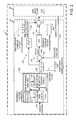
- FIG. 2is block diagram of the disk drive with emphasis on the components of the servo controller
- FIG. 3is a block diagram of a representative control loop embodiment wherein the reference position signal r(k) for each sample period and the related feed-forward values FF 1 , FF 2 , FF 3 , and FF 4 (four in this embodiment) are stored in suitable tables and provided to a suitable hardware-based state machine 220 for output as multi-rate digital demands u(k′′) at a 4 ⁇ rate;
- FIG. 4is a table representing the feed-forward durations for short to medium length seeks from as little as 1 track to as many as 160 tracks, that overall range being divided into five different sub-ranges;
- FIG. 5is a representative feed-forward table used for 1-2 track seeks, the first column representing the sample k (servo wedge), the second column representing the reference position signal r(k), and the third through sixth columns representing the feed-forward values that are used to output 4 ⁇ demands u(k′′) between 1 ⁇ servo samples;
- FIG. 6is a representative feed-forward table used for 3-15 track seeks, the remaining tables being longer but similarly configured;
- FIG. 7is a plot of the reference position signal r(k) from the 1-2 track seek table of FIG. 5, the reference position signal r(k) being used as is for a 1 track seek and scaled by a factor of 2 for a 2 track seek;
- FIG. 8is a plot of the feed-forward values from the 1-2 track seek table of FIG. 5, the feed-forward values being used as is for a 1 track seek and scaled by a factor of 2 for a 2 track seek.
- a disk drive 10generally comprises a servo controller 110 and a disk drive “plant” 150 .
- FIG. 1emphasizes the details of the plant 150 and
- FIG. 2emphasizes the details of the servo controller 110 including a multi-rate feed-forward control path 125 as discussed further below.
- the plant 150generally comprises a base 6 , a spindle motor 13 connected to the base 6 , and a magnetic disk 12 connected to the spindle motor 6 (only one is shown, but there are generally two or more disks).
- the plant 150also includes a swing-type actuator 30 consisting of a pivot body 40 that rotates on a pivot cartridge 41 , a voice coil motor 50 / 51 (e.g. a coil 50 and permanent magnets 51 ) extending to one side of the pivot body 40 , an actuator arm 60 extending from the other side of the pivot body 40 , and a head gimbal assembly (HGA) 70 that includes a transducer 80 .
- the particular transducer 80 shownincludes separate read and write transducers 81 , 82 as found in a magnetoresistive head (MR head), but single transducer heads such as a conventional inductive head (not shown) may also be used.
- MR headmagnetoresistive head
- the VCM 50 / 51moves the swing-type actuator 30 in response to a total command effort signal 111 received from the servo controller 110 and the transducer 80 periodically samples servo position information 15 recorded on the disk 12 at a servo sampling rate to produce an indicated position signal 151 .
- the servo sampling rateis determined by the number of servo sectors per revolution and the rotational speed of the disk 12 .
- FIG. 2is a block diagram of the servo controller 110 that receives the indicated position signal 151 and generates the total command effort signal 111 provided to the disk drive's VCM 50 / 51 for moving the swing-type actuator 30 to a target position 161 .
- the servo controller 110comprises a reference position generator 200 that receives the target position 161 and provides a reference position signal 162 that varies as a function of time along a shaped position profile 163 for moving the transducer 80 (see FIG. 1) from a start position to the target position in a controlled fashion.
- the reference position signal 162is provided to a feed-forward control path 125 and to a feedback control path 135 .
- the feed-forward control path 125receives the reference position signal 162 and applies a feed-forward command effort signal 126 at a feed-forward rate that is greater than the servo sampling rate—i.e. multi-rate—to move the actuator 30 more closely than otherwise possible along the shaped position profile 163 , between servo samples, during short seeks when relatively few servo samples are available.
- the feedback control path 135includes a combining junction 138 at its input that receives the reference position signal 162 and the indicated position signal 151 and applies a feedback command effort signal 136 at the servo sampling rate based on an error signal 164 representing the difference between the reference position signal 162 and the indicated position signal 151 .
- the feedback control path 135in essence, generally makes minor corrections at the servo sampling rate to compensate for any error remaining after application of prior multi-rate feed-forward command effort signals 126 .
- a combining junction 137combines the feedback command effort signal 136 with the feed-forward command effort signal 126 to form the total command effort signal 111 that is provided to the VCM 50 / 51 .
- the feed-forward command effort signal 126is multi-rate, i.e. is produced at a rate that exceeds the basic servo sampling rate.
- the feed-forward rateis preferably an integer multiple of the servo sampling rate such as 2 ⁇ , 3 ⁇ , or 4 ⁇ the servo sampling rate. Accordingly, the total command effort signal 111 consists most frequently of the feed-forward command effort signal 126 alone, and less frequently of a feed-forward command effort signal 126 combined with a feedback command effort signal 136 .
- the operation just describedmay be better understood with reference to the conceptual graphs 163 , 167 , 169 that are included in FIG. 2 and by remembering that the goal is to provide the plant 150 with a total command effort signal 111 that closely approximates a particular acceleration profile while effecting short to medium seeks that are, for example respectively, from 1 to 255 tracks and from 256 to 1,000 tracks in length.
- the preferred acceleration profileis a sinusoid because it contains only one frequency, but it might be desirable to vary somewhat from an exact sinusoid for even more improved settling. In either case, the primary contributor to the acceleration profile is the feed-forward command effort signal 126 .
- the conceptual graph 167 above the signal line carrying the feed-forward command effort signal 126shows that it has an effort expended (which translates to acceleration “a”) versus time profile (a “shaped effort profile”) that is sinusoidal.
- the conceptual graph 163 below the signal line carrying the reference position signal 162shows that it has a “distance-to-go” versus time profile (a “shaped position profile”) that varies from an initial distance-to-go to zero during a period of time corresponding to the anticipated number of servo samples needed to implement the seek (four in this case).
- the feed-forward command effort signal 126is, of course, related to the reference position signal 162 by the transfer function of the feed-forward control path 125 .
- the transfer function of the preferred feed-forward control path 125is simply a double time derivative of the reference position signal 162 , i.e. d 2 ⁇ /dt 2 .
- the transfer functioncould be more complicated if desired.
- the transfer functionmight include an inverse plant model such that the plant's response to the feed-forward command effort signal 126 more closely matches the ideal.
- the reference position generator 200generates a reference position signal 162 that produces a sinusoidal feed-forward command effort signal 126 .
- the reference position signal 162in other words, is the double integral of a sinusoid.
- the reference position generator 200outputs a reference position signal 162 that, when processed by the feed-forward control path 125 , produces a feed-forward command effort signal 126 that is sinusoidal.
- the feed-forward command effort signal 126is derived from a pre-computed lookup table that is indexed by the reference position signal 162 .
- the feedback control path 135unlike the feed-forward control path 125 , only produces an output at the servo sampling rate as suggested by the graph 169 that appears below the signal line carrying the feedback command effort signal 136 . In essence, the feedback control path 135 serves to correct any deviation between the expected position and the indicated position after application of the feed-forward command effort signal 126 due to modeling errors and/or perturbations.
- the feedback control path 135includes a compensator 120 that implements a transfer function D(z) that generally accounts for the modeled frequency response of the plant 150 . Compensator 120 is well known in the art therefore a detailed description is unnecessary to appreciate the present invention.
- the reference position generator 200is amenable to many embodiments. As suggested by FIG. 2, however, the preferred reference position generator 200 is implemented with firmware including functional blocks 210 that determines a seek length based on the difference between the target position 161 and a current position 220 . The reference position generator 200 then provides the seek length 211 to a functional block 230 that determines a corresponding seek time 231 (e.g. by way of a lookup table). Finally, both the seek length 211 and the seek time 231 are provided a generating block 240 that produces the reference position signal 162 .
- the reference position generator 200includes reference position signals that have been pre-computed (e.g. number of sample periods T s and corresponding position values). Seek lengths such as 1, 2, 4, 8 and 16 tracks, for example, have been set to 4, 4, 6, 12 and 16 sample periods T s , respectively.
- the feed-forward values defining the feed-forward command effort signal 126are also pre-computed.
- FIG. 3is a block diagram of a preferred control loop wherein the reference position signal r(k) for each sample period and the related feed-forward values FF 1 , FF 2 , FF 3 , and FF 4 (four in this embodiment) are stored in suitable tables and provided to a state machine 220 for output as multi-rate digital demands u(k′′).
- the control loopcomprises a controller chip 310 , a VCM driver chip 330 , the VCM 50 / 51 , the head 80 , and a read channel 90 .
- the functional equivalent of the servo controller 110 of FIG. 1is implemented by suitable portions of the controller chip 310 and the VCM driver chip 330 .
- the controller chip 310includes a microprocessor 312 for executing servo and non-servo programs.
- the microprocessorfor example, executes a servo control algorithm stored in a read-only memory (ROM) 313 .
- the controller chip 310receives host commands from a host (not shown) via a host I/O block 311 and receives an indicated position signal pe(k) from the channel 90 via a channel I/O block 315 .
- the controller chip 310would ordinarily develop a total command effort based on the difference m(k) between the target position and the indicated position signal 151 .
- the controller chip 310uniquely includes a table ROM 314 and a multi-rate state machine 320 that, concurrent with the execution of non-servo programs by the microprocessor 312 , autonomously applies a feed-forward command effort signal at a feed-forward rate that is greater than the servo sampling rate to move the transducer more closely along the shaped position profile between servo samples.
- the preferred state machine 320also implements, as suggested by FIG. 3, a notch filter function that dampens mechanical resonances while outputting multi-rate demands u(k′′) based on the feed-forward values stored in the table ROM 314 .
- the servo control firmwarewhich is running on the microprocessor 312 , accesses the appropriate data in the table ROM 314 , calculates a demand value m(k) by subtracting the indicated position 151 from a suitably scaled version of the reference position signal r(k), and then loads the demand value m(k) (ideally zero) and the feed-forward values FF 1 , FF 2 , FF 3 , FF 4 into corresponding registers in the state machine 320 .
- the state machine 320thereafter process these values at a 4 ⁇ rate in order to output four successive digital demands u(k′′) at a 4 ⁇ rate based on the demand value m(k) and the feed-forward values FF 1 , FF 2 , FF 3 , FF 4 .
- the preferred state machineis a notch filter implemented as a second order digital filter that operates according to this equation:
- u ( k ′′)A 0 n ( k ′′)+ A 1 n ( k ′′ ⁇ 1) ⁇ B 1 u ( k ′′ ⁇ 1) ⁇ B 2 u ( k ′′ ⁇ 2)
- n(k′′)is the input to the filter
- u(k′′)is the output of the filter
- a 0 ,A 1 ,A 2 ,B 1 and B 2are constant coefficients that determine the behavior of the filter.
- the overall filteruses a chain of four filters FLTR 1 , FLTR 2 , FLTR 3 , FLTR 4 .
- the state machine 320is oversampled at a 4 ⁇ rate (as compared with the servo sample rate) and the first filter FLTR 1 is provided with a combination of the feedback-computed demand value m(k) and the following sequence of four inputs n 1 (k) as suggested by the combining junction 321 of FIG. 3 :
- n 1 ( k ′′)m ( k ′′)+ FF 1
- n 1 ( k ′′+1)m ( k ′′)+ FF 2
- n 1 ( k ′′+1)m ( k ′′)+ FF 3
- n 1 ( k ′′+1)m ( k ′′)+ FF 4
- n 2 ( k ′′)u 1 ( k ′′)
- n 3 ( k ′′)u 2 ( k ′′)
- n 4 ( k ′′)u 3 ( k ′′)
- the VCM driver chip 330contain a DAC 331 that receives the digital demands u(k′′) from the state machine 320 and converts them to an analog value (typically a voltage) that is further provided to a suitable drive circuit 332 that drives the VCM 50 / 51 (typically with current).
- a DAC 331that receives the digital demands u(k′′) from the state machine 320 and converts them to an analog value (typically a voltage) that is further provided to a suitable drive circuit 332 that drives the VCM 50 / 51 (typically with current).
- FIG. 4is a table representing the feed-forward durations for short to medium length seeks from as little as 1 track to as many as 160 tracks.
- the overall range of tracks from 1 to 160is divided into five different sub-ranges that have difference feed-forward durations ranging from 6 to 28 samples k.
- FIG. 5represents a first one of the five feed-forward tables that are stored in the table ROM 314 , this one used for 1-2 track seeks.
- the first columnrepresents the sample k (servo wedge)
- the second columnrepresents the reference position signal r(k)
- the third through sixth columnsrepresent the feed-forward values FF 1 , FF 2 , FF 3 , FF 4 that are used to output demands u(k′′) at a 4 ⁇ rate, in between servo samples that are received at a 1 ⁇ rate.
- FIG. 6is a representative feed-forward table used for 3-15 track seeks. The other three tables (not shown) are longer but are otherwise similarly configured.
- FIG. 7is a plot of the reference position signal r(k) from the 1-2 track seek table of FIG. 5 .
- the values for the reference position signal r(k)provide maximum resolution given a 16-bit two's complement representation and are normalized to a one track seek.
- the reference position signal r(k)is used without modification, therefore, for a 1 track seek and is scaled by a factor of 2 for a 2 track seek.
- the other tablesare similarly normalized to a one track seek such that the values of the reference position signal r(k) are conveniently scaled in a like manner.
- FIG. 8is a plot of the feed-forward values from the 1-2 track seek table of FIG. 5 .
- the feed-forward valuesare also normalized to a one-track situation so that they are easily scaled for seeks of various lengths. Note that in this actual case, the acceleration profile represented by FIG. 8 is a modified sinusoid that has been found to provide better performance than a true sinusoid.
Landscapes
- Moving Of Head For Track Selection And Changing (AREA)
Abstract
Description
Claims (20)
Priority Applications (1)
| Application Number | Priority Date | Filing Date | Title |
|---|---|---|---|
| US09/538,931US6614618B1 (en) | 2000-03-31 | 2000-03-31 | Disk drive with feed-forward control path that receives a reference position signal to apply a feed-forward command effort at a rate greater than a servo sampling rate |
Applications Claiming Priority (1)
| Application Number | Priority Date | Filing Date | Title |
|---|---|---|---|
| US09/538,931US6614618B1 (en) | 2000-03-31 | 2000-03-31 | Disk drive with feed-forward control path that receives a reference position signal to apply a feed-forward command effort at a rate greater than a servo sampling rate |
Publications (1)
| Publication Number | Publication Date |
|---|---|
| US6614618B1true US6614618B1 (en) | 2003-09-02 |
Family
ID=27766390
Family Applications (1)
| Application Number | Title | Priority Date | Filing Date |
|---|---|---|---|
| US09/538,931Expired - LifetimeUS6614618B1 (en) | 2000-03-31 | 2000-03-31 | Disk drive with feed-forward control path that receives a reference position signal to apply a feed-forward command effort at a rate greater than a servo sampling rate |
Country Status (1)
| Country | Link |
|---|---|
| US (1) | US6614618B1 (en) |
Cited By (111)
| Publication number | Priority date | Publication date | Assignee | Title |
|---|---|---|---|---|
| US20040267494A1 (en)* | 2003-06-26 | 2004-12-30 | Hanson Reed David | Guiding a sensor using a broadly-curved lateral profile |
| WO2005010870A1 (en)* | 2003-06-26 | 2005-02-03 | Seagate Technology Llc | Guiding a sensor using a broadly-curved lateral profile |
| US20050259348A1 (en)* | 2003-04-11 | 2005-11-24 | Tao Zhang | Method and apparatus for reducing vibration in a dynamic system |
| US20070053098A1 (en)* | 2005-08-24 | 2007-03-08 | Seagate Technology Llc | Controller with fractional position algorithm |
| US20080004825A1 (en)* | 2006-03-29 | 2008-01-03 | Flake Lance L | Optimized transmission of signals between a disk drive controller and a motor controller using a serial port |
| US20120078446A1 (en)* | 2010-09-28 | 2012-03-29 | The Boeing Company | Integrated Upsampler and Filtering for Multi-Rate Controller for Electro-Mechanical Flight Actuation System |
| US8179626B1 (en) | 2009-12-04 | 2012-05-15 | Western Digital Technologies, Inc. | Adaptive shock detection |
| US8634158B1 (en) | 2011-11-16 | 2014-01-21 | Western Digital Technologies, Inc. | Disk drive generating feed-forward actuator compensation based on a speaker driver signal |
| US8737013B2 (en) | 2011-11-16 | 2014-05-27 | Western Digital Technologies, Inc. | Disk drive selecting disturbance signal for feed-forward compensation |
| US8824081B1 (en) | 2012-03-13 | 2014-09-02 | Western Digital Technologies, Inc. | Disk drive employing radially coherent reference pattern for servo burst demodulation and fly height measurement |
| US8830617B1 (en) | 2013-05-30 | 2014-09-09 | Western Digital Technologies, Inc. | Disk drive adjusting state estimator to compensate for unreliable servo data |
| US8879191B1 (en) | 2012-11-14 | 2014-11-04 | Western Digital Technologies, Inc. | Disk drive modifying rotational position optimization algorithm to achieve target performance for limited stroke |
| US8891194B1 (en) | 2013-05-14 | 2014-11-18 | Western Digital Technologies, Inc. | Disk drive iteratively adapting correction value that compensates for non-linearity of head |
| US8891191B1 (en) | 2014-05-06 | 2014-11-18 | Western Digital Technologies, Inc. | Data storage device initializing read signal gain to detect servo seed pattern |
| US8896955B1 (en) | 2010-08-31 | 2014-11-25 | Western Digital Technologies, Inc. | Adaptive track follow control |
| US8896957B1 (en) | 2013-05-10 | 2014-11-25 | Western Digital Technologies, Inc. | Disk drive performing spiral scan of disk surface to detect residual data |
| US8902539B1 (en) | 2014-05-13 | 2014-12-02 | Western Digital Technologies, Inc. | Data storage device reducing seek power consumption |
| US8902538B1 (en) | 2013-03-29 | 2014-12-02 | Western Digital Technologies, Inc. | Disk drive detecting crack in microactuator |
| US8913342B1 (en) | 2014-03-21 | 2014-12-16 | Western Digital Technologies, Inc. | Data storage device adjusting range of microactuator digital-to-analog converter based on operating temperature |
| US8917475B1 (en) | 2013-12-20 | 2014-12-23 | Western Digital Technologies, Inc. | Disk drive generating a disk locked clock using radial dependent timing feed-forward compensation |
| US8917474B1 (en) | 2011-08-08 | 2014-12-23 | Western Digital Technologies, Inc. | Disk drive calibrating a velocity profile prior to writing a spiral track |
| US8922931B1 (en) | 2013-05-13 | 2014-12-30 | Western Digital Technologies, Inc. | Disk drive releasing variable amount of buffered write data based on sliding window of predicted servo quality |
| US8922940B1 (en) | 2014-05-27 | 2014-12-30 | Western Digital Technologies, Inc. | Data storage device reducing spindle motor voltage boost during power failure |
| US8922937B1 (en) | 2012-04-19 | 2014-12-30 | Western Digital Technologies, Inc. | Disk drive evaluating multiple vibration sensor outputs to enable write-protection |
| US8922938B1 (en) | 2012-11-02 | 2014-12-30 | Western Digital Technologies, Inc. | Disk drive filtering disturbance signal and error signal for adaptive feed-forward compensation |
| US8929021B1 (en) | 2012-03-27 | 2015-01-06 | Western Digital Technologies, Inc. | Disk drive servo writing from spiral tracks using radial dependent timing feed-forward compensation |
| US8929022B1 (en) | 2012-12-19 | 2015-01-06 | Western Digital Technologies, Inc. | Disk drive detecting microactuator degradation by evaluating frequency component of servo signal |
| US8934186B1 (en) | 2014-03-26 | 2015-01-13 | Western Digital Technologies, Inc. | Data storage device estimating servo zone to reduce size of track address |
| US8937784B1 (en) | 2012-08-01 | 2015-01-20 | Western Digital Technologies, Inc. | Disk drive employing feed-forward compensation and phase shift compensation during seek settling |
| US8941945B1 (en) | 2014-06-06 | 2015-01-27 | Western Digital Technologies, Inc. | Data storage device servoing heads based on virtual servo tracks |
| US8941939B1 (en) | 2013-10-24 | 2015-01-27 | Western Digital Technologies, Inc. | Disk drive using VCM BEMF feed-forward compensation to write servo data to a disk |
| US8947819B1 (en) | 2012-08-28 | 2015-02-03 | Western Digital Technologies, Inc. | Disk drive implementing hysteresis for primary shock detector based on a more sensitive secondary shock detector |
| US8953271B1 (en) | 2013-05-13 | 2015-02-10 | Western Digital Technologies, Inc. | Disk drive compensating for repeatable run out selectively per zone |
| US8958169B1 (en) | 2014-06-11 | 2015-02-17 | Western Digital Technologies, Inc. | Data storage device re-qualifying state estimator while decelerating head |
| US8970979B1 (en) | 2013-12-18 | 2015-03-03 | Western Digital Technologies, Inc. | Disk drive determining frequency response of actuator near servo sample frequency |
| US8982490B1 (en) | 2014-04-24 | 2015-03-17 | Western Digital Technologies, Inc. | Data storage device reading first spiral track while simultaneously writing second spiral track |
| US8982501B1 (en) | 2014-09-22 | 2015-03-17 | Western Digital Technologies, Inc. | Data storage device compensating for repeatable disturbance when commutating a spindle motor |
| US8995082B1 (en) | 2011-06-03 | 2015-03-31 | Western Digital Technologies, Inc. | Reducing acoustic noise in a disk drive when exiting idle mode |
| US8995075B1 (en) | 2012-06-21 | 2015-03-31 | Western Digital Technologies, Inc. | Disk drive adjusting estimated servo state to compensate for transient when crossing a servo zone boundary |
| US9001454B1 (en) | 2013-04-12 | 2015-04-07 | Western Digital Technologies, Inc. | Disk drive adjusting phase of adaptive feed-forward controller when reconfiguring servo loop |
| US9007714B1 (en) | 2014-07-18 | 2015-04-14 | Western Digital Technologies Inc. | Data storage device comprising slew rate anti-windup compensation for microactuator |
| US9013825B1 (en) | 2014-03-24 | 2015-04-21 | Western Digital Technologies, Inc. | Electronic system with vibration management mechanism and method of operation thereof |
| US9013824B1 (en) | 2014-06-04 | 2015-04-21 | Western Digital Technologies, Inc. | Data storage device comprising dual read sensors and dual servo channels to improve servo demodulation |
| US9026728B1 (en) | 2013-06-06 | 2015-05-05 | Western Digital Technologies, Inc. | Disk drive applying feed-forward compensation when writing consecutive data tracks |
| US9025269B1 (en) | 2014-01-02 | 2015-05-05 | Western Digital Technologies, Inc. | Disk drive compensating for cycle slip of disk locked clock when reading mini-wedge |
| US9047901B1 (en) | 2013-05-28 | 2015-06-02 | Western Digital Technologies, Inc. | Disk drive measuring spiral track error by measuring a slope of a spiral track across a disk radius |
| US9047932B1 (en) | 2014-03-21 | 2015-06-02 | Western Digital Technologies, Inc. | Data storage device adjusting a power loss threshold based on samples of supply voltage |
| US9047919B1 (en) | 2013-03-12 | 2015-06-02 | Western Digitial Technologies, Inc. | Disk drive initializing servo read channel by reading data preceding servo preamble during access operation |
| US9053727B1 (en) | 2014-06-02 | 2015-06-09 | Western Digital Technologies, Inc. | Disk drive opening spiral crossing window based on DC and AC spiral track error |
| US9053726B1 (en) | 2014-01-29 | 2015-06-09 | Western Digital Technologies, Inc. | Data storage device on-line adapting disturbance observer filter |
| US9053712B1 (en) | 2014-05-07 | 2015-06-09 | Western Digital Technologies, Inc. | Data storage device reading servo sector while writing data sector |
| US9058834B1 (en) | 2013-11-08 | 2015-06-16 | Western Digital Technologies, Inc. | Power architecture for low power modes in storage devices |
| US9058827B1 (en) | 2013-06-25 | 2015-06-16 | Western Digitial Technologies, Inc. | Disk drive optimizing filters based on sensor signal and disturbance signal for adaptive feed-forward compensation |
| US9058826B1 (en) | 2014-02-13 | 2015-06-16 | Western Digital Technologies, Inc. | Data storage device detecting free fall condition from disk speed variations |
| US9064537B1 (en) | 2013-09-13 | 2015-06-23 | Western Digital Technologies, Inc. | Disk drive measuring radial offset between heads by detecting a difference between ramp contact |
| US9076471B1 (en) | 2013-07-31 | 2015-07-07 | Western Digital Technologies, Inc. | Fall detection scheme using FFS |
| US9076490B1 (en) | 2012-12-12 | 2015-07-07 | Western Digital Technologies, Inc. | Disk drive writing radial offset spiral servo tracks by reading spiral seed tracks |
| US9076472B1 (en) | 2014-08-21 | 2015-07-07 | Western Digital (Fremont), Llc | Apparatus enabling writing servo data when disk reaches target rotation speed |
| US9076473B1 (en) | 2014-08-12 | 2015-07-07 | Western Digital Technologies, Inc. | Data storage device detecting fly height instability of head during load operation based on microactuator response |
| US9093105B2 (en) | 2011-12-09 | 2015-07-28 | Western Digital Technologies, Inc. | Disk drive charging capacitor using motor supply voltage during power failure |
| US9099147B1 (en) | 2014-09-22 | 2015-08-04 | Western Digital Technologies, Inc. | Data storage device commutating a spindle motor using closed-loop rotation phase alignment |
| US9111575B1 (en) | 2014-10-23 | 2015-08-18 | Western Digital Technologies, Inc. | Data storage device employing adaptive feed-forward control in timing loop to compensate for vibration |
| US9129630B1 (en) | 2014-12-16 | 2015-09-08 | Western Digital Technologies, Inc. | Data storage device employing full servo sectors on first disk surface and mini servo sectors on second disk surface |
| US9142235B1 (en) | 2009-10-27 | 2015-09-22 | Western Digital Technologies, Inc. | Disk drive characterizing microactuator by injecting sinusoidal disturbance and evaluating feed-forward compensation values |
| US9141177B1 (en) | 2014-03-21 | 2015-09-22 | Western Digital Technologies, Inc. | Data storage device employing glitch compensation for power loss detection |
| US9142225B1 (en) | 2014-03-21 | 2015-09-22 | Western Digital Technologies, Inc. | Electronic system with actuator control mechanism and method of operation thereof |
| US9142249B1 (en) | 2013-12-06 | 2015-09-22 | Western Digital Technologies, Inc. | Disk drive using timing loop control signal for vibration compensation in servo loop |
| US9147428B1 (en) | 2013-04-24 | 2015-09-29 | Western Digital Technologies, Inc. | Disk drive with improved spin-up control |
| US9147418B1 (en) | 2013-06-20 | 2015-09-29 | Western Digital Technologies, Inc. | Disk drive compensating for microactuator gain variations |
| US9153283B1 (en) | 2014-09-30 | 2015-10-06 | Western Digital Technologies, Inc. | Data storage device compensating for hysteretic response of microactuator |
| US9165583B1 (en) | 2014-10-29 | 2015-10-20 | Western Digital Technologies, Inc. | Data storage device adjusting seek profile based on seek length when ending track is near ramp |
| US9171567B1 (en) | 2014-05-27 | 2015-10-27 | Western Digital Technologies, Inc. | Data storage device employing sliding mode control of spindle motor |
| US9171568B1 (en) | 2014-06-25 | 2015-10-27 | Western Digital Technologies, Inc. | Data storage device periodically re-initializing spindle motor commutation sequence based on timing data |
| US9208808B1 (en) | 2014-04-22 | 2015-12-08 | Western Digital Technologies, Inc. | Electronic system with unload management mechanism and method of operation thereof |
| US9208810B1 (en) | 2014-04-24 | 2015-12-08 | Western Digital Technologies, Inc. | Data storage device attenuating interference from first spiral track when reading second spiral track |
| US9208815B1 (en) | 2014-10-09 | 2015-12-08 | Western Digital Technologies, Inc. | Data storage device dynamically reducing coast velocity during seek to reduce power consumption |
| US9214175B1 (en) | 2015-03-16 | 2015-12-15 | Western Digital Technologies, Inc. | Data storage device configuring a gain of a servo control system for actuating a head over a disk |
| US9230593B1 (en) | 2014-12-23 | 2016-01-05 | Western Digital Technologies, Inc. | Data storage device optimizing spindle motor power when transitioning into a power failure mode |
| US9230592B1 (en) | 2014-12-23 | 2016-01-05 | Western Digital Technologies, Inc. | Electronic system with a method of motor spindle bandwidth estimation and calibration thereof |
| US9245560B1 (en) | 2015-03-09 | 2016-01-26 | Western Digital Technologies, Inc. | Data storage device measuring reader/writer offset by reading spiral track and concentric servo sectors |
| US9245540B1 (en) | 2014-10-29 | 2016-01-26 | Western Digital Technologies, Inc. | Voice coil motor temperature sensing circuit to reduce catastrophic failure due to voice coil motor coil shorting to ground |
| US9245577B1 (en) | 2015-03-26 | 2016-01-26 | Western Digital Technologies, Inc. | Data storage device comprising spindle motor current sensing with supply voltage noise attenuation |
| US9251823B1 (en) | 2014-12-10 | 2016-02-02 | Western Digital Technologies, Inc. | Data storage device delaying seek operation to avoid thermal asperities |
| US9269386B1 (en) | 2014-01-29 | 2016-02-23 | Western Digital Technologies, Inc. | Data storage device on-line adapting disturbance observer filter |
| US9286927B1 (en) | 2014-12-16 | 2016-03-15 | Western Digital Technologies, Inc. | Data storage device demodulating servo burst by computing slope of intermediate integration points |
| US9286925B1 (en) | 2015-03-26 | 2016-03-15 | Western Digital Technologies, Inc. | Data storage device writing multiple burst correction values at the same radial location |
| US9343102B1 (en) | 2015-03-25 | 2016-05-17 | Western Digital Technologies, Inc. | Data storage device employing a phase offset to generate power from a spindle motor during a power failure |
| US9343094B1 (en) | 2015-03-26 | 2016-05-17 | Western Digital Technologies, Inc. | Data storage device filtering burst correction values before downsampling the burst correction values |
| US9350278B1 (en) | 2014-06-13 | 2016-05-24 | Western Digital Technologies, Inc. | Circuit technique to integrate voice coil motor support elements |
| US9349401B1 (en) | 2014-07-24 | 2016-05-24 | Western Digital Technologies, Inc. | Electronic system with media scan mechanism and method of operation thereof |
| US9355676B1 (en) | 2015-03-25 | 2016-05-31 | Western Digital Technologies, Inc. | Data storage device controlling amplitude and phase of driving voltage to generate power from a spindle motor |
| US9355667B1 (en) | 2014-11-11 | 2016-05-31 | Western Digital Technologies, Inc. | Data storage device saving absolute position at each servo wedge for previous write operations |
| US9361939B1 (en) | 2014-03-10 | 2016-06-07 | Western Digital Technologies, Inc. | Data storage device characterizing geometry of magnetic transitions |
| US9396751B1 (en) | 2015-06-26 | 2016-07-19 | Western Digital Technologies, Inc. | Data storage device compensating for fabrication tolerances when measuring spindle motor current |
| US9407015B1 (en) | 2014-12-29 | 2016-08-02 | Western Digital Technologies, Inc. | Automatic power disconnect device |
| US9418689B2 (en) | 2014-10-09 | 2016-08-16 | Western Digital Technologies, Inc. | Data storage device generating an operating seek time profile as a function of a base seek time profile |
| US9424871B1 (en) | 2012-09-13 | 2016-08-23 | Western Digital Technologies, Inc. | Disk drive correcting an error in a detected gray code |
| US9424868B1 (en) | 2015-05-12 | 2016-08-23 | Western Digital Technologies, Inc. | Data storage device employing spindle motor driving profile during seek to improve power performance |
| US9437231B1 (en) | 2015-09-25 | 2016-09-06 | Western Digital Technologies, Inc. | Data storage device concurrently controlling and sensing a secondary actuator for actuating a head over a disk |
| US9437237B1 (en) | 2015-02-20 | 2016-09-06 | Western Digital Technologies, Inc. | Method to detect power loss through data storage device spindle speed |
| US9454212B1 (en) | 2014-12-08 | 2016-09-27 | Western Digital Technologies, Inc. | Wakeup detector |
| US9471072B1 (en) | 2013-11-14 | 2016-10-18 | Western Digital Technologies, Inc | Self-adaptive voltage scaling |
| US9484733B1 (en) | 2013-09-11 | 2016-11-01 | Western Digital Technologies, Inc. | Power control module for data storage device |
| US9542966B1 (en) | 2015-07-09 | 2017-01-10 | Western Digital Technologies, Inc. | Data storage devices and methods with frequency-shaped sliding mode control |
| US9564162B1 (en) | 2015-12-28 | 2017-02-07 | Western Digital Technologies, Inc. | Data storage device measuring resonant frequency of a shock sensor by applying differential excitation and measuring oscillation |
| US9581978B1 (en) | 2014-12-17 | 2017-02-28 | Western Digital Technologies, Inc. | Electronic system with servo management mechanism and method of operation thereof |
| US9620160B1 (en) | 2015-12-28 | 2017-04-11 | Western Digital Technologies, Inc. | Data storage device measuring resonant frequency of a shock sensor by inserting the shock sensor into an oscillator circuit |
| US9823294B1 (en) | 2013-10-29 | 2017-11-21 | Western Digital Technologies, Inc. | Negative voltage testing methodology and tester |
| US9886285B2 (en) | 2015-03-31 | 2018-02-06 | Western Digital Technologies, Inc. | Communication interface initialization |
| US9899834B1 (en) | 2015-11-18 | 2018-02-20 | Western Digital Technologies, Inc. | Power control module using protection circuit for regulating backup voltage to power load during power fault |
| US9959204B1 (en) | 2015-03-09 | 2018-05-01 | Western Digital Technologies, Inc. | Tracking sequential ranges of non-ordered data |
Citations (3)
| Publication number | Priority date | Publication date | Assignee | Title |
|---|---|---|---|---|
| US4775903A (en)* | 1986-10-14 | 1988-10-04 | Hewlett-Packard Company | Sampled servo seek and track follow system for a magnetic disc drive |
| US5721648A (en) | 1992-04-10 | 1998-02-24 | Seagate Technology, Inc. | Multirate digital control system for use with a system having a linear transfer function, such as a head positioning system in a magnetic disc drive |
| US5859742A (en) | 1995-11-17 | 1999-01-12 | Fujitsu Limited | Disk storage apparatus having head overshoot and undershoot control |
- 2000
- 2000-03-31USUS09/538,931patent/US6614618B1/ennot_activeExpired - Lifetime
Patent Citations (3)
| Publication number | Priority date | Publication date | Assignee | Title |
|---|---|---|---|---|
| US4775903A (en)* | 1986-10-14 | 1988-10-04 | Hewlett-Packard Company | Sampled servo seek and track follow system for a magnetic disc drive |
| US5721648A (en) | 1992-04-10 | 1998-02-24 | Seagate Technology, Inc. | Multirate digital control system for use with a system having a linear transfer function, such as a head positioning system in a magnetic disc drive |
| US5859742A (en) | 1995-11-17 | 1999-01-12 | Fujitsu Limited | Disk storage apparatus having head overshoot and undershoot control |
Cited By (123)
| Publication number | Priority date | Publication date | Assignee | Title |
|---|---|---|---|---|
| US20050259348A1 (en)* | 2003-04-11 | 2005-11-24 | Tao Zhang | Method and apparatus for reducing vibration in a dynamic system |
| US7046478B2 (en)* | 2003-04-11 | 2006-05-16 | Seagate Technology Llc | Method and apparatus for reducing vibration in a dynamic system |
| WO2005010870A1 (en)* | 2003-06-26 | 2005-02-03 | Seagate Technology Llc | Guiding a sensor using a broadly-curved lateral profile |
| US6930851B2 (en) | 2003-06-26 | 2005-08-16 | Seagate Technology Llc | Guiding a sensor using a broadly-curved lateral profile |
| US20040267494A1 (en)* | 2003-06-26 | 2004-12-30 | Hanson Reed David | Guiding a sensor using a broadly-curved lateral profile |
| US7843661B2 (en) | 2005-08-24 | 2010-11-30 | Seagate Technology Llc | Controller with fractional position algorithm |
| US20070053098A1 (en)* | 2005-08-24 | 2007-03-08 | Seagate Technology Llc | Controller with fractional position algorithm |
| US8078773B2 (en) | 2006-03-29 | 2011-12-13 | Broadcom Corporation | Optimized transmission of signals between a disk drive controller and a motor controller using a serial port |
| US20080004825A1 (en)* | 2006-03-29 | 2008-01-03 | Flake Lance L | Optimized transmission of signals between a disk drive controller and a motor controller using a serial port |
| US9142235B1 (en) | 2009-10-27 | 2015-09-22 | Western Digital Technologies, Inc. | Disk drive characterizing microactuator by injecting sinusoidal disturbance and evaluating feed-forward compensation values |
| US8179626B1 (en) | 2009-12-04 | 2012-05-15 | Western Digital Technologies, Inc. | Adaptive shock detection |
| US8896955B1 (en) | 2010-08-31 | 2014-11-25 | Western Digital Technologies, Inc. | Adaptive track follow control |
| US20120078446A1 (en)* | 2010-09-28 | 2012-03-29 | The Boeing Company | Integrated Upsampler and Filtering for Multi-Rate Controller for Electro-Mechanical Flight Actuation System |
| US8653780B2 (en)* | 2010-09-28 | 2014-02-18 | The Boeing Company | Integrated upsampler and filtering for multi-rate controller for electro-mechanical flight actuation system |
| US9405277B2 (en) | 2010-09-28 | 2016-08-02 | The Boeing Company | Integrated upsampler and filtering for multi-rate controller for electromechanical flight actuation system |
| US8995082B1 (en) | 2011-06-03 | 2015-03-31 | Western Digital Technologies, Inc. | Reducing acoustic noise in a disk drive when exiting idle mode |
| US8917474B1 (en) | 2011-08-08 | 2014-12-23 | Western Digital Technologies, Inc. | Disk drive calibrating a velocity profile prior to writing a spiral track |
| US8634158B1 (en) | 2011-11-16 | 2014-01-21 | Western Digital Technologies, Inc. | Disk drive generating feed-forward actuator compensation based on a speaker driver signal |
| US8953278B1 (en) | 2011-11-16 | 2015-02-10 | Western Digital Technologies, Inc. | Disk drive selecting disturbance signal for feed-forward compensation |
| US8737013B2 (en) | 2011-11-16 | 2014-05-27 | Western Digital Technologies, Inc. | Disk drive selecting disturbance signal for feed-forward compensation |
| US9390749B2 (en) | 2011-12-09 | 2016-07-12 | Western Digital Technologies, Inc. | Power failure management in disk drives |
| US9093105B2 (en) | 2011-12-09 | 2015-07-28 | Western Digital Technologies, Inc. | Disk drive charging capacitor using motor supply voltage during power failure |
| US8824081B1 (en) | 2012-03-13 | 2014-09-02 | Western Digital Technologies, Inc. | Disk drive employing radially coherent reference pattern for servo burst demodulation and fly height measurement |
| US8934191B1 (en) | 2012-03-27 | 2015-01-13 | Western Digital Technologies, Inc. | Disk drive generating a disk locked clock using radial dependent timing feed-forward compensation |
| US8929021B1 (en) | 2012-03-27 | 2015-01-06 | Western Digital Technologies, Inc. | Disk drive servo writing from spiral tracks using radial dependent timing feed-forward compensation |
| US8922937B1 (en) | 2012-04-19 | 2014-12-30 | Western Digital Technologies, Inc. | Disk drive evaluating multiple vibration sensor outputs to enable write-protection |
| US8995075B1 (en) | 2012-06-21 | 2015-03-31 | Western Digital Technologies, Inc. | Disk drive adjusting estimated servo state to compensate for transient when crossing a servo zone boundary |
| US9454989B1 (en) | 2012-06-21 | 2016-09-27 | Western Digital Technologies, Inc. | Disk drive adjusting estimated servo state to compensate for transient when crossing a servo zone boundary |
| US8937784B1 (en) | 2012-08-01 | 2015-01-20 | Western Digital Technologies, Inc. | Disk drive employing feed-forward compensation and phase shift compensation during seek settling |
| US8947819B1 (en) | 2012-08-28 | 2015-02-03 | Western Digital Technologies, Inc. | Disk drive implementing hysteresis for primary shock detector based on a more sensitive secondary shock detector |
| US9424871B1 (en) | 2012-09-13 | 2016-08-23 | Western Digital Technologies, Inc. | Disk drive correcting an error in a detected gray code |
| US8922938B1 (en) | 2012-11-02 | 2014-12-30 | Western Digital Technologies, Inc. | Disk drive filtering disturbance signal and error signal for adaptive feed-forward compensation |
| US8879191B1 (en) | 2012-11-14 | 2014-11-04 | Western Digital Technologies, Inc. | Disk drive modifying rotational position optimization algorithm to achieve target performance for limited stroke |
| US9076490B1 (en) | 2012-12-12 | 2015-07-07 | Western Digital Technologies, Inc. | Disk drive writing radial offset spiral servo tracks by reading spiral seed tracks |
| US8929022B1 (en) | 2012-12-19 | 2015-01-06 | Western Digital Technologies, Inc. | Disk drive detecting microactuator degradation by evaluating frequency component of servo signal |
| US9047919B1 (en) | 2013-03-12 | 2015-06-02 | Western Digitial Technologies, Inc. | Disk drive initializing servo read channel by reading data preceding servo preamble during access operation |
| US8902538B1 (en) | 2013-03-29 | 2014-12-02 | Western Digital Technologies, Inc. | Disk drive detecting crack in microactuator |
| US9001454B1 (en) | 2013-04-12 | 2015-04-07 | Western Digital Technologies, Inc. | Disk drive adjusting phase of adaptive feed-forward controller when reconfiguring servo loop |
| US9147428B1 (en) | 2013-04-24 | 2015-09-29 | Western Digital Technologies, Inc. | Disk drive with improved spin-up control |
| US8896957B1 (en) | 2013-05-10 | 2014-11-25 | Western Digital Technologies, Inc. | Disk drive performing spiral scan of disk surface to detect residual data |
| US8922931B1 (en) | 2013-05-13 | 2014-12-30 | Western Digital Technologies, Inc. | Disk drive releasing variable amount of buffered write data based on sliding window of predicted servo quality |
| US8953271B1 (en) | 2013-05-13 | 2015-02-10 | Western Digital Technologies, Inc. | Disk drive compensating for repeatable run out selectively per zone |
| US8891194B1 (en) | 2013-05-14 | 2014-11-18 | Western Digital Technologies, Inc. | Disk drive iteratively adapting correction value that compensates for non-linearity of head |
| US9047901B1 (en) | 2013-05-28 | 2015-06-02 | Western Digital Technologies, Inc. | Disk drive measuring spiral track error by measuring a slope of a spiral track across a disk radius |
| US8830617B1 (en) | 2013-05-30 | 2014-09-09 | Western Digital Technologies, Inc. | Disk drive adjusting state estimator to compensate for unreliable servo data |
| US9026728B1 (en) | 2013-06-06 | 2015-05-05 | Western Digital Technologies, Inc. | Disk drive applying feed-forward compensation when writing consecutive data tracks |
| US9147418B1 (en) | 2013-06-20 | 2015-09-29 | Western Digital Technologies, Inc. | Disk drive compensating for microactuator gain variations |
| US9058827B1 (en) | 2013-06-25 | 2015-06-16 | Western Digitial Technologies, Inc. | Disk drive optimizing filters based on sensor signal and disturbance signal for adaptive feed-forward compensation |
| US9076471B1 (en) | 2013-07-31 | 2015-07-07 | Western Digital Technologies, Inc. | Fall detection scheme using FFS |
| US9484733B1 (en) | 2013-09-11 | 2016-11-01 | Western Digital Technologies, Inc. | Power control module for data storage device |
| US9064537B1 (en) | 2013-09-13 | 2015-06-23 | Western Digital Technologies, Inc. | Disk drive measuring radial offset between heads by detecting a difference between ramp contact |
| US8941939B1 (en) | 2013-10-24 | 2015-01-27 | Western Digital Technologies, Inc. | Disk drive using VCM BEMF feed-forward compensation to write servo data to a disk |
| US9823294B1 (en) | 2013-10-29 | 2017-11-21 | Western Digital Technologies, Inc. | Negative voltage testing methodology and tester |
| US9058834B1 (en) | 2013-11-08 | 2015-06-16 | Western Digital Technologies, Inc. | Power architecture for low power modes in storage devices |
| US9471072B1 (en) | 2013-11-14 | 2016-10-18 | Western Digital Technologies, Inc | Self-adaptive voltage scaling |
| US9142249B1 (en) | 2013-12-06 | 2015-09-22 | Western Digital Technologies, Inc. | Disk drive using timing loop control signal for vibration compensation in servo loop |
| US8970979B1 (en) | 2013-12-18 | 2015-03-03 | Western Digital Technologies, Inc. | Disk drive determining frequency response of actuator near servo sample frequency |
| US8917475B1 (en) | 2013-12-20 | 2014-12-23 | Western Digital Technologies, Inc. | Disk drive generating a disk locked clock using radial dependent timing feed-forward compensation |
| US9025269B1 (en) | 2014-01-02 | 2015-05-05 | Western Digital Technologies, Inc. | Disk drive compensating for cycle slip of disk locked clock when reading mini-wedge |
| US9269386B1 (en) | 2014-01-29 | 2016-02-23 | Western Digital Technologies, Inc. | Data storage device on-line adapting disturbance observer filter |
| US9053726B1 (en) | 2014-01-29 | 2015-06-09 | Western Digital Technologies, Inc. | Data storage device on-line adapting disturbance observer filter |
| US9058826B1 (en) | 2014-02-13 | 2015-06-16 | Western Digital Technologies, Inc. | Data storage device detecting free fall condition from disk speed variations |
| US9361939B1 (en) | 2014-03-10 | 2016-06-07 | Western Digital Technologies, Inc. | Data storage device characterizing geometry of magnetic transitions |
| US8913342B1 (en) | 2014-03-21 | 2014-12-16 | Western Digital Technologies, Inc. | Data storage device adjusting range of microactuator digital-to-analog converter based on operating temperature |
| US9142225B1 (en) | 2014-03-21 | 2015-09-22 | Western Digital Technologies, Inc. | Electronic system with actuator control mechanism and method of operation thereof |
| US9141177B1 (en) | 2014-03-21 | 2015-09-22 | Western Digital Technologies, Inc. | Data storage device employing glitch compensation for power loss detection |
| US9047932B1 (en) | 2014-03-21 | 2015-06-02 | Western Digital Technologies, Inc. | Data storage device adjusting a power loss threshold based on samples of supply voltage |
| US9013825B1 (en) | 2014-03-24 | 2015-04-21 | Western Digital Technologies, Inc. | Electronic system with vibration management mechanism and method of operation thereof |
| US8934186B1 (en) | 2014-03-26 | 2015-01-13 | Western Digital Technologies, Inc. | Data storage device estimating servo zone to reduce size of track address |
| US9208808B1 (en) | 2014-04-22 | 2015-12-08 | Western Digital Technologies, Inc. | Electronic system with unload management mechanism and method of operation thereof |
| US9208810B1 (en) | 2014-04-24 | 2015-12-08 | Western Digital Technologies, Inc. | Data storage device attenuating interference from first spiral track when reading second spiral track |
| US8982490B1 (en) | 2014-04-24 | 2015-03-17 | Western Digital Technologies, Inc. | Data storage device reading first spiral track while simultaneously writing second spiral track |
| US8891191B1 (en) | 2014-05-06 | 2014-11-18 | Western Digital Technologies, Inc. | Data storage device initializing read signal gain to detect servo seed pattern |
| US9053712B1 (en) | 2014-05-07 | 2015-06-09 | Western Digital Technologies, Inc. | Data storage device reading servo sector while writing data sector |
| US8902539B1 (en) | 2014-05-13 | 2014-12-02 | Western Digital Technologies, Inc. | Data storage device reducing seek power consumption |
| US8922940B1 (en) | 2014-05-27 | 2014-12-30 | Western Digital Technologies, Inc. | Data storage device reducing spindle motor voltage boost during power failure |
| US9171567B1 (en) | 2014-05-27 | 2015-10-27 | Western Digital Technologies, Inc. | Data storage device employing sliding mode control of spindle motor |
| US9053727B1 (en) | 2014-06-02 | 2015-06-09 | Western Digital Technologies, Inc. | Disk drive opening spiral crossing window based on DC and AC spiral track error |
| US9013824B1 (en) | 2014-06-04 | 2015-04-21 | Western Digital Technologies, Inc. | Data storage device comprising dual read sensors and dual servo channels to improve servo demodulation |
| US8941945B1 (en) | 2014-06-06 | 2015-01-27 | Western Digital Technologies, Inc. | Data storage device servoing heads based on virtual servo tracks |
| US8958169B1 (en) | 2014-06-11 | 2015-02-17 | Western Digital Technologies, Inc. | Data storage device re-qualifying state estimator while decelerating head |
| US9350278B1 (en) | 2014-06-13 | 2016-05-24 | Western Digital Technologies, Inc. | Circuit technique to integrate voice coil motor support elements |
| US9171568B1 (en) | 2014-06-25 | 2015-10-27 | Western Digital Technologies, Inc. | Data storage device periodically re-initializing spindle motor commutation sequence based on timing data |
| US9007714B1 (en) | 2014-07-18 | 2015-04-14 | Western Digital Technologies Inc. | Data storage device comprising slew rate anti-windup compensation for microactuator |
| US9349401B1 (en) | 2014-07-24 | 2016-05-24 | Western Digital Technologies, Inc. | Electronic system with media scan mechanism and method of operation thereof |
| US9076473B1 (en) | 2014-08-12 | 2015-07-07 | Western Digital Technologies, Inc. | Data storage device detecting fly height instability of head during load operation based on microactuator response |
| US9076472B1 (en) | 2014-08-21 | 2015-07-07 | Western Digital (Fremont), Llc | Apparatus enabling writing servo data when disk reaches target rotation speed |
| US8982501B1 (en) | 2014-09-22 | 2015-03-17 | Western Digital Technologies, Inc. | Data storage device compensating for repeatable disturbance when commutating a spindle motor |
| US9099147B1 (en) | 2014-09-22 | 2015-08-04 | Western Digital Technologies, Inc. | Data storage device commutating a spindle motor using closed-loop rotation phase alignment |
| US9153283B1 (en) | 2014-09-30 | 2015-10-06 | Western Digital Technologies, Inc. | Data storage device compensating for hysteretic response of microactuator |
| US9418689B2 (en) | 2014-10-09 | 2016-08-16 | Western Digital Technologies, Inc. | Data storage device generating an operating seek time profile as a function of a base seek time profile |
| US9208815B1 (en) | 2014-10-09 | 2015-12-08 | Western Digital Technologies, Inc. | Data storage device dynamically reducing coast velocity during seek to reduce power consumption |
| US9111575B1 (en) | 2014-10-23 | 2015-08-18 | Western Digital Technologies, Inc. | Data storage device employing adaptive feed-forward control in timing loop to compensate for vibration |
| US9245540B1 (en) | 2014-10-29 | 2016-01-26 | Western Digital Technologies, Inc. | Voice coil motor temperature sensing circuit to reduce catastrophic failure due to voice coil motor coil shorting to ground |
| US9165583B1 (en) | 2014-10-29 | 2015-10-20 | Western Digital Technologies, Inc. | Data storage device adjusting seek profile based on seek length when ending track is near ramp |
| US9355667B1 (en) | 2014-11-11 | 2016-05-31 | Western Digital Technologies, Inc. | Data storage device saving absolute position at each servo wedge for previous write operations |
| US9454212B1 (en) | 2014-12-08 | 2016-09-27 | Western Digital Technologies, Inc. | Wakeup detector |
| US9251823B1 (en) | 2014-12-10 | 2016-02-02 | Western Digital Technologies, Inc. | Data storage device delaying seek operation to avoid thermal asperities |
| US9286927B1 (en) | 2014-12-16 | 2016-03-15 | Western Digital Technologies, Inc. | Data storage device demodulating servo burst by computing slope of intermediate integration points |
| US9129630B1 (en) | 2014-12-16 | 2015-09-08 | Western Digital Technologies, Inc. | Data storage device employing full servo sectors on first disk surface and mini servo sectors on second disk surface |
| US9581978B1 (en) | 2014-12-17 | 2017-02-28 | Western Digital Technologies, Inc. | Electronic system with servo management mechanism and method of operation thereof |
| US9230592B1 (en) | 2014-12-23 | 2016-01-05 | Western Digital Technologies, Inc. | Electronic system with a method of motor spindle bandwidth estimation and calibration thereof |
| US9761266B2 (en) | 2014-12-23 | 2017-09-12 | Western Digital Technologies, Inc. | Data storage device optimizing spindle motor power when transitioning into a power failure mode |
| US9230593B1 (en) | 2014-12-23 | 2016-01-05 | Western Digital Technologies, Inc. | Data storage device optimizing spindle motor power when transitioning into a power failure mode |
| US9407015B1 (en) | 2014-12-29 | 2016-08-02 | Western Digital Technologies, Inc. | Automatic power disconnect device |
| US9437237B1 (en) | 2015-02-20 | 2016-09-06 | Western Digital Technologies, Inc. | Method to detect power loss through data storage device spindle speed |
| US9959204B1 (en) | 2015-03-09 | 2018-05-01 | Western Digital Technologies, Inc. | Tracking sequential ranges of non-ordered data |
| US9245560B1 (en) | 2015-03-09 | 2016-01-26 | Western Digital Technologies, Inc. | Data storage device measuring reader/writer offset by reading spiral track and concentric servo sectors |
| US9214175B1 (en) | 2015-03-16 | 2015-12-15 | Western Digital Technologies, Inc. | Data storage device configuring a gain of a servo control system for actuating a head over a disk |
| US9343102B1 (en) | 2015-03-25 | 2016-05-17 | Western Digital Technologies, Inc. | Data storage device employing a phase offset to generate power from a spindle motor during a power failure |
| US9355676B1 (en) | 2015-03-25 | 2016-05-31 | Western Digital Technologies, Inc. | Data storage device controlling amplitude and phase of driving voltage to generate power from a spindle motor |
| US9245577B1 (en) | 2015-03-26 | 2016-01-26 | Western Digital Technologies, Inc. | Data storage device comprising spindle motor current sensing with supply voltage noise attenuation |
| US9286925B1 (en) | 2015-03-26 | 2016-03-15 | Western Digital Technologies, Inc. | Data storage device writing multiple burst correction values at the same radial location |
| US9343094B1 (en) | 2015-03-26 | 2016-05-17 | Western Digital Technologies, Inc. | Data storage device filtering burst correction values before downsampling the burst correction values |
| US9886285B2 (en) | 2015-03-31 | 2018-02-06 | Western Digital Technologies, Inc. | Communication interface initialization |
| US9424868B1 (en) | 2015-05-12 | 2016-08-23 | Western Digital Technologies, Inc. | Data storage device employing spindle motor driving profile during seek to improve power performance |
| US9396751B1 (en) | 2015-06-26 | 2016-07-19 | Western Digital Technologies, Inc. | Data storage device compensating for fabrication tolerances when measuring spindle motor current |
| US9542966B1 (en) | 2015-07-09 | 2017-01-10 | Western Digital Technologies, Inc. | Data storage devices and methods with frequency-shaped sliding mode control |
| US9437231B1 (en) | 2015-09-25 | 2016-09-06 | Western Digital Technologies, Inc. | Data storage device concurrently controlling and sensing a secondary actuator for actuating a head over a disk |
| US9899834B1 (en) | 2015-11-18 | 2018-02-20 | Western Digital Technologies, Inc. | Power control module using protection circuit for regulating backup voltage to power load during power fault |
| US10127952B2 (en) | 2015-11-18 | 2018-11-13 | Western Digital Technologies, Inc. | Power control module using protection circuit for regulating backup voltage to power load during power fault |
| US9620160B1 (en) | 2015-12-28 | 2017-04-11 | Western Digital Technologies, Inc. | Data storage device measuring resonant frequency of a shock sensor by inserting the shock sensor into an oscillator circuit |
| US9564162B1 (en) | 2015-12-28 | 2017-02-07 | Western Digital Technologies, Inc. | Data storage device measuring resonant frequency of a shock sensor by applying differential excitation and measuring oscillation |
Similar Documents
| Publication | Publication Date | Title |
|---|---|---|
| US6614618B1 (en) | Disk drive with feed-forward control path that receives a reference position signal to apply a feed-forward command effort at a rate greater than a servo sampling rate | |
| US6952322B1 (en) | Disk drive reading servo sectors recorded at a relative offset on multiple disk surfaces to increase the servo sample rate | |
| US6614615B1 (en) | Disk drive with adaptive control path that produces an adaptive control effort based on a characterized deviation between actual and modeled plant response | |
| US6636377B1 (en) | Method of tuning feed-forward control in a disk drive | |
| US6178060B1 (en) | Current profile shaping to reduce disc drive seek time variation and acoustic noise generation | |
| US7253989B1 (en) | Disk drive compensation of bias imparted by a flex circuit cable utilizing a dual bias curve estimation scheme | |
| US5917672A (en) | Disk file head positioning servo system incorporating adaptive saturated seek and head offset compensation | |
| US7110214B1 (en) | Disk drive to implement a seek operation utilizing a deceleration velocity profile that mathematically models BEMFs | |
| US6924960B1 (en) | Timing compensation in a self-servowriting system | |
| JP3742483B2 (en) | Head positioning control method for hard disk drive | |
| JP2578297B2 (en) | Direct access storage device and its operation method | |
| US11514939B2 (en) | Split-actuator drive that coordinates timing of aggressor and victim for effective victim disturbance-feedforward | |
| US12148456B2 (en) | Split actuator drive that limits slew rate of aggressor VCM to reduce victim disturbances | |
| US6721124B2 (en) | Method and apparatus for providing an intelligent settle scheme for a hard disk drive with dual stage actuators | |
| KR100424268B1 (en) | Sliding mode control of a magnetoresistive read head for magnetic recording | |
| US6785080B1 (en) | Method and apparatus for providing a variable rate oversampling digital filter for resonance compensation in disk drive servo control systems | |
| US6490120B1 (en) | Servo gain optimization using a variable convergence factor | |
| JPH1145523A (en) | Magnetic disk drive and head positioning control system applied to the same | |
| CN101071575A (en) | Magnetic disk device and head-position control method | |
| US6018432A (en) | Disc drive operational response using idle mode compensation | |
| JP2003249045A (en) | Disk unit | |
| US7016141B2 (en) | Settle, rotational/linear vibration, and track follow controller optimization with shared state controller | |
| US7394613B2 (en) | Control device, disk device, and seek orbit generation method | |
| JP2697641B2 (en) | Resonance suppression method for multi-rate sample rate of magnetic disk drive | |
| US6160674A (en) | Stable data writing method by tracking head speed in hard disk drive |
Legal Events
| Date | Code | Title | Description |
|---|---|---|---|
| AS | Assignment | Owner name:WESTERN DIGITAL CORPORATION, CALIFORNIA Free format text:ASSIGNMENT OF ASSIGNORS INTEREST;ASSIGNORS:SHEH, EDGAR D.;TRIEU, THAO P.;NAZARIAN, ARA W.;AND OTHERS;REEL/FRAME:010915/0429;SIGNING DATES FROM 20000414 TO 20000630 | |
| AS | Assignment | Owner name:GENERAL ELECTRIC CAPITAL CORPORATION, CALIFORNIA Free format text:SECURITY AGREEMENT;ASSIGNOR:WESTERN DIGITAL CORPORATION;REEL/FRAME:011170/0948 Effective date:20000920 | |
| AS | Assignment | Owner name:WESTERN DIGITAL TECHNOLOGIES, INC., CALIFORNIA Free format text:AMENDED AND RESTATED CERTIFICATE OF INCORPORATION OF WESTERN DIGITAL CORP.;ASSIGNOR:WESTERN DIGITAL CORPORATION;REEL/FRAME:011967/0481 Effective date:20010406 | |
| STCF | Information on status: patent grant | Free format text:PATENTED CASE | |
| FPAY | Fee payment | Year of fee payment:4 | |
| SULP | Surcharge for late payment | ||
| AS | Assignment | Owner name:WESTERN DIGITAL TECHNOLOGIES, INC., CALIFORNIA Free format text:RELEASE BY SECURED PARTY;ASSIGNOR:GENERAL ELECTRIC CAPITAL CORPORATION, AS AGENT;REEL/FRAME:021502/0451 Effective date:20070809 | |
| FPAY | Fee payment | Year of fee payment:8 | |
| SULP | Surcharge for late payment | Year of fee payment:7 | |
| FPAY | Fee payment | Year of fee payment:12 | |
| SULP | Surcharge for late payment | Year of fee payment:11 | |
| AS | Assignment | Owner name:JPMORGAN CHASE BANK, N.A., AS COLLATERAL AGENT, ILLINOIS Free format text:SECURITY AGREEMENT;ASSIGNOR:WESTERN DIGITAL TECHNOLOGIES, INC.;REEL/FRAME:038744/0481 Effective date:20160512 Owner name:U.S. BANK NATIONAL ASSOCIATION, AS COLLATERAL AGENT, CALIFORNIA Free format text:SECURITY AGREEMENT;ASSIGNOR:WESTERN DIGITAL TECHNOLOGIES, INC.;REEL/FRAME:038744/0281 Effective date:20160512 Owner name:JPMORGAN CHASE BANK, N.A., AS COLLATERAL AGENT, ILLINOIS Free format text:SECURITY AGREEMENT;ASSIGNOR:WESTERN DIGITAL TECHNOLOGIES, INC.;REEL/FRAME:038722/0229 Effective date:20160512 Owner name:JPMORGAN CHASE BANK, N.A., AS COLLATERAL AGENT, IL Free format text:SECURITY AGREEMENT;ASSIGNOR:WESTERN DIGITAL TECHNOLOGIES, INC.;REEL/FRAME:038722/0229 Effective date:20160512 Owner name:JPMORGAN CHASE BANK, N.A., AS COLLATERAL AGENT, IL Free format text:SECURITY AGREEMENT;ASSIGNOR:WESTERN DIGITAL TECHNOLOGIES, INC.;REEL/FRAME:038744/0481 Effective date:20160512 Owner name:U.S. BANK NATIONAL ASSOCIATION, AS COLLATERAL AGEN Free format text:SECURITY AGREEMENT;ASSIGNOR:WESTERN DIGITAL TECHNOLOGIES, INC.;REEL/FRAME:038744/0281 Effective date:20160512 | |
| AS | Assignment | Owner name:WESTERN DIGITAL TECHNOLOGIES, INC., CALIFORNIA Free format text:RELEASE BY SECURED PARTY;ASSIGNOR:U.S. BANK NATIONAL ASSOCIATION, AS COLLATERAL AGENT;REEL/FRAME:045501/0714 Effective date:20180227 | |
| AS | Assignment | Owner name:WESTERN DIGITAL TECHNOLOGIES, INC., CALIFORNIA Free format text:RELEASE OF SECURITY INTEREST AT REEL 038744 FRAME 0481;ASSIGNOR:JPMORGAN CHASE BANK, N.A.;REEL/FRAME:058982/0556 Effective date:20220203 |