US6614521B2 - Device for verifying the accuracy of a spectral analyzer - Google Patents
Device for verifying the accuracy of a spectral analyzerDownload PDFInfo
- Publication number
- US6614521B2 US6614521B2US10/186,274US18627402AUS6614521B2US 6614521 B2US6614521 B2US 6614521B2US 18627402 AUS18627402 AUS 18627402AUS 6614521 B2US6614521 B2US 6614521B2
- Authority
- US
- United States
- Prior art keywords
- light
- artificial member
- artificial
- cap
- scattering
- Prior art date
- Legal status (The legal status is an assumption and is not a legal conclusion. Google has not performed a legal analysis and makes no representation as to the accuracy of the status listed.)
- Expired - Lifetime
Links
Images


Classifications
- B—PERFORMING OPERATIONS; TRANSPORTING
- B82—NANOTECHNOLOGY
- B82Y—SPECIFIC USES OR APPLICATIONS OF NANOSTRUCTURES; MEASUREMENT OR ANALYSIS OF NANOSTRUCTURES; MANUFACTURE OR TREATMENT OF NANOSTRUCTURES
- B82Y15/00—Nanotechnology for interacting, sensing or actuating, e.g. quantum dots as markers in protein assays or molecular motors
- A—HUMAN NECESSITIES
- A61—MEDICAL OR VETERINARY SCIENCE; HYGIENE
- A61B—DIAGNOSIS; SURGERY; IDENTIFICATION
- A61B5/00—Measuring for diagnostic purposes; Identification of persons
- A61B5/145—Measuring characteristics of blood in vivo, e.g. gas concentration or pH-value ; Measuring characteristics of body fluids or tissues, e.g. interstitial fluid or cerebral tissue
- A61B5/1455—Measuring characteristics of blood in vivo, e.g. gas concentration or pH-value ; Measuring characteristics of body fluids or tissues, e.g. interstitial fluid or cerebral tissue using optical sensors, e.g. spectral photometrical oximeters
- A—HUMAN NECESSITIES
- A61—MEDICAL OR VETERINARY SCIENCE; HYGIENE
- A61B—DIAGNOSIS; SURGERY; IDENTIFICATION
- A61B5/00—Measuring for diagnostic purposes; Identification of persons
- A61B5/145—Measuring characteristics of blood in vivo, e.g. gas concentration or pH-value ; Measuring characteristics of body fluids or tissues, e.g. interstitial fluid or cerebral tissue
- A61B5/1495—Calibrating or testing of in-vivo probes
- G—PHYSICS
- G01—MEASURING; TESTING
- G01N—INVESTIGATING OR ANALYSING MATERIALS BY DETERMINING THEIR CHEMICAL OR PHYSICAL PROPERTIES
- G01N21/00—Investigating or analysing materials by the use of optical means, i.e. using sub-millimetre waves, infrared, visible or ultraviolet light
- G01N21/17—Systems in which incident light is modified in accordance with the properties of the material investigated
- G01N21/47—Scattering, i.e. diffuse reflection
- G01N21/4785—Standardising light scatter apparatus; Standards therefor
- A—HUMAN NECESSITIES
- A61—MEDICAL OR VETERINARY SCIENCE; HYGIENE
- A61B—DIAGNOSIS; SURGERY; IDENTIFICATION
- A61B2560/00—Constructional details of operational features of apparatus; Accessories for medical measuring apparatus
- A61B2560/02—Operational features
- A61B2560/0223—Operational features of calibration, e.g. protocols for calibrating sensors
- A61B2560/0228—Operational features of calibration, e.g. protocols for calibrating sensors using calibration standards
- A61B2560/0233—Optical standards
- A—HUMAN NECESSITIES
- A61—MEDICAL OR VETERINARY SCIENCE; HYGIENE
- A61B—DIAGNOSIS; SURGERY; IDENTIFICATION
- A61B5/00—Measuring for diagnostic purposes; Identification of persons
- A61B5/145—Measuring characteristics of blood in vivo, e.g. gas concentration or pH-value ; Measuring characteristics of body fluids or tissues, e.g. interstitial fluid or cerebral tissue
- A61B5/14532—Measuring characteristics of blood in vivo, e.g. gas concentration or pH-value ; Measuring characteristics of body fluids or tissues, e.g. interstitial fluid or cerebral tissue for measuring glucose, e.g. by tissue impedance measurement
- Y—GENERAL TAGGING OF NEW TECHNOLOGICAL DEVELOPMENTS; GENERAL TAGGING OF CROSS-SECTIONAL TECHNOLOGIES SPANNING OVER SEVERAL SECTIONS OF THE IPC; TECHNICAL SUBJECTS COVERED BY FORMER USPC CROSS-REFERENCE ART COLLECTIONS [XRACs] AND DIGESTS
- Y10—TECHNICAL SUBJECTS COVERED BY FORMER USPC
- Y10S—TECHNICAL SUBJECTS COVERED BY FORMER USPC CROSS-REFERENCE ART COLLECTIONS [XRACs] AND DIGESTS
- Y10S977/00—Nanotechnology
- Y10S977/902—Specified use of nanostructure
- Y10S977/904—Specified use of nanostructure for medical, immunological, body treatment, or diagnosis
- Y10S977/926—Topical chemical, e.g. cosmetic or sunscreen
- Y—GENERAL TAGGING OF NEW TECHNOLOGICAL DEVELOPMENTS; GENERAL TAGGING OF CROSS-SECTIONAL TECHNOLOGIES SPANNING OVER SEVERAL SECTIONS OF THE IPC; TECHNICAL SUBJECTS COVERED BY FORMER USPC CROSS-REFERENCE ART COLLECTIONS [XRACs] AND DIGESTS
- Y10—TECHNICAL SUBJECTS COVERED BY FORMER USPC
- Y10S—TECHNICAL SUBJECTS COVERED BY FORMER USPC CROSS-REFERENCE ART COLLECTIONS [XRACs] AND DIGESTS
- Y10S977/00—Nanotechnology
- Y10S977/902—Specified use of nanostructure
- Y10S977/932—Specified use of nanostructure for electronic or optoelectronic application
- Y10S977/953—Detector using nanostructure
- Y10S977/954—Of radiant energy
- Y—GENERAL TAGGING OF NEW TECHNOLOGICAL DEVELOPMENTS; GENERAL TAGGING OF CROSS-SECTIONAL TECHNOLOGIES SPANNING OVER SEVERAL SECTIONS OF THE IPC; TECHNICAL SUBJECTS COVERED BY FORMER USPC CROSS-REFERENCE ART COLLECTIONS [XRACs] AND DIGESTS
- Y10—TECHNICAL SUBJECTS COVERED BY FORMER USPC
- Y10S—TECHNICAL SUBJECTS COVERED BY FORMER USPC CROSS-REFERENCE ART COLLECTIONS [XRACs] AND DIGESTS
- Y10S977/00—Nanotechnology
- Y10S977/902—Specified use of nanostructure
- Y10S977/932—Specified use of nanostructure for electronic or optoelectronic application
- Y10S977/953—Detector using nanostructure
- Y10S977/957—Of chemical property or presence
- Y10S977/958—Of biomolecule property
Definitions
- This inventionis in the field of non-invasive spectral analysis of analytes in tissues and relates more particularly to a device which may be used with a non-invasive monitoring system used for determining concentrations of various blood components.
- Non-invasive devicesexist which are used externally to measure either the concentration of the constituent in gases admitted by the body or the concentrations contained in a patient's body part, typically a finger.
- U.S. Pat. No. 5,429,128describes a finger receptor that receives a finger of a user and is for use with a non-invasive monitoring device, such as that described in U.S. Pat. No. 5,361,758.
- the present inventorshave developed a device shaped to fit a receptor that is operatively connected to a non-invasive monitoring device, which device is useful in monitoring the precision and accuracy of the non-invasive monitoring device and which permits photometric correction of the instrument.
- the inventionprovides a method and a device made of materials for carrying out the method which reproduces absorption spectra associated with various body parts when such parts are subjected to spectral determination.
- a device according to the present inventionis made of a material that exhibits the same light scattering and absorbency characteristics as a body part, preferably of an earlobe, lip, fold of skin or finger, most preferably, a finger.
- an artificial memberthat mimics the absorbance spectrum of a body part and includes the spectral components of blood analytes comprising a light scattering and reflecting material, which member has a chamber portion comprising one or more chambers, the member configures to be reproducibly received in a measuring receptor that is operatively connected to a non-invasive monitoring device, preferably, the body part that is mimicked is a finger.
- a measuring receptorthat is operatively connected to a non-invasive monitoring device, preferably, the body part that is mimicked is a finger.
- there is one chamberwhile in another, there are two chambers.
- each chamberis filled with an O-cellulose material that mimics light scattering properties of tissue, preferably each chamber is filled with a gel material containing amaranth dye and sodium benzoate and holding light scattering and reflective particles that mimic the light scattering properties of tissue.
- the material that fills each chamberis fluid free.
- the reflective particlescomprise Teflon®-PTFE (polytetrafluoroethylene) (DuPont, Wilmington, Del., USA), titanium dioxide (TiO 2 ) or are polystyrene nanospheres.
- the light scattering and reflecting material of the memberis Teflon®-PTFE, preferably the configuration of the member wherein the configuration of the member to be reproducibly received, comprises a stabilizing member extending from the chamber portion to reversibly urge other surfaces of the member into contact with the measuring receptor, preferably the stabilizing member is as depicted in FIG. 9 .
- a method of transferring algorithms from one spectral instrument to anotherthe method involving: measuring a spectral response of a member in a first spectral instrument; measuring a spectral response of the member in a second spectral instrument; determining any difference in measurements between the first instrument and the second instrument; and modifying the algorithms of the instruments to account for any difference
- the member of the methodmimics the absorbance spectrum of a body part and includes the spectral components of blood analytes comprising a light scattering and reflecting material, which member has a chamber portion comprising one or more chambers, the member configures to be reproducibly received in a measuring receptor, that is operatively connected to a non-invasive monioring device, preferably the body part mimicked is a finger.
- there is one chamberwhile in another there are two chambers.
- each chamberis filled with an O-cellulose material that mimics light scattering properties of tissue, preferably each chamber is filled with a gel material containing amaranth dye and sodium benzoate and holding light scattering and reflective particles that mimic the light scattering properties of tissue.
- the material that fills each chamberis fluid free.
- the reflective particlescomprise Teflon®-PTFE, TiO 2 or are polystyrene nanospheres.
- the light scattering and reflecting material of the memberis Teflon®-PTFE, preferably the configuration of the member wherein the configuration of the member to be reproducibly received, comprises a stabilizing member extending from the chamber portion to reversibly urge other surfaces of the member into contact with the measuring receptor, preferably the stabilizing member is as depicted in FIG. 9 .
- the inventionin another embodiment, provides a method for mimicking the absorbance spectrum of a body part that includes the spectral components of blood analytes, and comprises inserting a member in a measuring device operatively connected to a non-invasive monitoring device; taking measurements with the device and comparing the results with those obtained from a body part of a subject that the member is intended to mimic, wherein the member is comprised of a light scattering and reflecting material, which member is configured to be reproducibly received in the measuring receptor.
- the membermimics the absorbance spectrum of a body part and includes the spectral components of blood analytes comprising a light scattering and reflecting material, and the member has a chamber portion comprising one or more chambers, the member configured to be reproducibly received in a measuring receptor that is operatively connected to a non-invasive monitoring device, preferably the body part that is mimicked is a finger.
- a measuring receptorthat is operatively connected to a non-invasive monitoring device, preferably the body part that is mimicked is a finger.
- there is one chamberwhile in another there are two chambers.
- each chamberis filled with an O-cellulose material which mimics light scattering properties of tissue
- each chamberis filled with a gel material containing amaranth dye and sodium benzoate and holding light scattering and reflective particles which mimic the light scattering properties of tissue.
- the material that fills each chamberis fluid free.
- the reflective particlescomprise Teflon®-PTFE, TiO 2 or are polystyrene nanospheres.
- the light scattering and reflecting material of the memberis Teflon®-PTFE, preferably the configuration of the member wherein the configuration of the member to be reproducibly received, comprises a stabilizing member extending from the chamber portion to reversibly urge other surfaces of the member into contact with the measuring receptor, preferably the stabilizing member is as depicted in FIG. 9 .
- the present inventionprovides an artificial member that mimics the absorbance spectrum of a body part and includes the spectral components of blood analytes, the artificial member comprising a container made of a light-scattering and reflecting material, the container comprising at least one chamber, the container having a neck extending from one end thereof, the neck comprising an orifice that is sealed with a cap, the member being configured to be reproducibly received in a measuring receptor that is operatively connected to a non-invasive monitoring device.
- the memberfurther comprises a septum that fits over the orifice and is secured by the cap.
- the septumis uniform with the cap.
- the neckcomprises a flange, and the cap is secured over the flange.
- the flangeis an annular flange.
- the capis a crimp cap, that is preferably made of aluminum.
- the body part, which is mimickedis a finger.
- the membercontains one chamber, while in another it contains two chambers.
- the chamberis cylindrical.
- each chamberis filled with an O-cellulose material that mimics light scattering properties of tissue.
- each chamberis filled with a gel material containing amaranth dye and sodium benzoate and holding light scattering and reflective particles that mimic the light scattering properties of tissue.
- the material that fills each chamberis fluid free.
- the reflective particlescomprise Teflon®-PTFE, TiO 2 or are polystyrene nanospheres.
- the light scattering and reflecting material of the memberis Teflon®-PTFE, preferably the Teflon®-PTFE contains from about 0.1% to about 25% glass fiber. More preferably, the Teflon®-PTFE contains from about 0.1% to about 5% glass fiber.
- the membercomprises a stabilizing member extending from the chamber portion to reversibly urge other surfaces of the member into contact with the measuring receptor.
- the present inventionprovides a method for mimicking the absorbance spectrum of a body part that includes the spectral components of blood analytes, the method comprises:
- an artificial membercomprising a container made of a light scattering and reflecting material, the container comprising one or more chambers, and having a neck extending from one end thereof, the neck comprising an orifice sealed with a cap, the artificial member being configured to be reproducibly received in a measuring receptor that is operatively connected to a non-invasive monitoring device;
- step (d)comparing the measurements obtained in step (c) with those obtained from a body part of a subject, which the artificial member is configured to mimic.
- the artificial member used in the methodfurther comprises a septum that fits over the orifice and is secured by the cap.
- the septumis uniform with the cap.
- FIG. 1shows absorbance spectra from 500-1380 nm for globulins, glucose, urea, creatinine, cholesterol and human serum albumin with water displacement compensation;
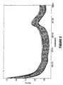
- FIG. 2shows 2013 absorbance spectra from 585-1100 nm for the finger from 32 subjects
- FIG. 3shows absorbance spectra (580-1100 for water in a subject's finger and an artificial member of the present invention
- FIG. 4shows absorbance spectra from 580-1100 nm for a subject's finger and an artificial member as shown in FIG. 3, as well the curve representing the difference between the first two spectra;
- FIG. 5is absorbance spectra from 580-1100 nm for water in a finger and in an artificial member of the invention wherein the member contains pink sponge (SCOTCH BRITE®, commercially available from 3M, St. Paul, Minn. USA) and water;
- the membercontains pink sponge (SCOTCH BRITE®, commercially available from 3M, St. Paul, Minn. USA) and water;
- FIG. 6is absorbance spectra from 580-1100 nm for water in a finger and in an artificial member of the invention wherein the member contains polystyrene nanospheres in water and gelatin, plus amaranth dye and sodium benzoate as a preservative;
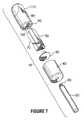
- FIG. 7is an isometric exploded view of an artificial member according to the present invention in a configuration for use with a finger receptor;
- FIG. 8is a side view of the member of FIG. 7;
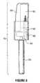
- FIG. 9is an isometric exploded view of a further embodiment of an artificial member according to the present invention in a configuration for use with a finger receptor;
- FIG. 10is a side view of the member of FIG. 9;
- FIG. 11is a side view of an assembled member of FIGS. 9 and 10;
- FIG. 12is an isometric exploded view of a further embodiment of an artificial member according to the present invention in a configuration for use with a finger receptor;
- FIG. 13is a partial section of the artificial member shown in FIG. 12 taken along the line 13 — 13 ;
- FIG. 14is an isometric view of an assembled member of FIGS. 12 and 13.
- FIG. 15shows an artificial finger according to the present invention used in association with a finger receptor, which is operatively connected to a non-invasive monitoring device.
- concentrationor “concentration level” means the amount or quantity of a constituent in a solution whether the solution is in vitro or in vivo.
- carbohydratesmeans a substance, or analyte found in a tissue and includes carbohydrates such as, for example, glucose, bilirubin, a protein, for example, albumin or hemoglobin.
- fluid freemeans having no appreciable amount of liquid present.
- tissuemeans any tissue of the body of a subject, including for example, blood, extracellular spaces, and can mean the entire composition of a body part such as a finger or ear lobe.
- subjectmeans any member of the animal kingdom including, preferably, humans.
- the present inventorshave prepared a device that is capable of insertion in a receptor that is used with a non-invasive monitoring device.
- the use of such a device or artificial memberis to enable the user of such a monitoring device to quickly and easily check the precision and accuracy of the non-invasive monitoring device.
- Spectral dataobtained using a standard spectrophotometer and compensated for water displacememt, were collected from in vitro measurement of a cuvette containing samples of various blood constituents, and are illustrated in FIG. 1 .
- the spectra associated with the various constituentsare complex.
- the spectra for a living fingeris relatively simple, particularly in the 500-1100 nm region. This may be seen in FIG. 2 . Measurements taken in this region are relatively consistent regardless of individual measurements or the individual being scanned. In this respect. the data presented in FIG. 2 represent the combined spectra of 33 people for whom a total of 2,013 measurements were taken and collectively presented.
- an artificial membermust be able to provide a spectrum that is comparable to those presented in FIG. 2 or the absorbance spectra of another body part. It will be appreciated that in order to develop a comparable artificial member, such member must mimic the situation where light is directed to a body part. Light entering the body is scattered and that light that emerges radiates in virtually every direction. Absorption begins at the point where the light enters the tissue. In the case of transmission, as the light passes through the tissue, more and more light is absorbed as the path length increases. Clearly, if the path length is too great, very little light is left for measurement and the absorbance calculations will be subject to considerable error due to noise. These considerations are also true in respect of the artificial member.
- an artificial member of the present inventionis made of a highly reflective material such as, for example, Teflon®, especially Teflon®-PTFE virgin material.
- Teflon®especially Teflon®-PTFE virgin material.
- the artificial membermush show sufficient internal reflectance to achieve a comparable result.
- a chamber, or container spaceexists in the member, although, depending on the body part being mimicked, reflective material may comprise part of the internal structure of the chamber of the member.
- an artificial membermust be capable of being easily inserted into and removed from a receptor that is used to measure spectral characteristics of constituents in a body part.
- the shape of the artificial memberwill be determined by the shape of the receptor.
- the artificial memberIn the case of a finger receptor, the artificial member must have corresponding shapes to ensure that there is a constant path length from the point at which light is delivered to the finger or artificial finger and the point at which light exits the finger or artificial body part.
- an artificial member of the present inventionis for use in association with any measuring receptor that is combined with any non-invasive monitoring device that is based on the principle of measuring the absorbance (or reflectance) of radiation passing through (or reflecting from) a body part.
- such devicesoperate according to the Beer-Lambert law, namely that the concentration of constituents is proportional to a constant of proportionality (the extinction coefficient), the path length, and the absorbance (LOG 10 [1/T], wherein T is the transmittance, i.e., the proportion of light of a given wavelength that is transmitted through the matrix).
- any other constituent, or constituentsmay be used.
- the constituentswill be preferably held in the member, preferably in the chamber or chambers of the member. In some applications, it may be necessary to introduce other absorbing or reflecting material(s) in the chamber or intermixed with the composition of the reflective material.
- absorbance measurementsmay be taken, and without limiting the scope of the applicability of the present invention, two such methods are: (1) using light from a scanning monochromator, pass it through a selected part of the body and collect the light transmitted through onto a silicon detector, and then measure the amount of light transmitted in the absence of the body part. With these two measurements, the transmittance, and hence the absorbance, may be calculated; and (2) using a polychromatic light source, pass it through the body part to be measured, collect the light, collimate it onto a diffraction grating and focus the different wavelengths of light on a linear array detector. Each element of the array will then measure the intensity of light for a narrow band of wavelengths (sample scan).
- the present inventionincludes artificial members replicating each of these body parts.
- One of the problems encountered in measuring absorbance in tissueis the spectral variability from one instrument to another due to physical differences in light transmission and collection. Because the phantom finger is designed to minimize variability of spectral response and physical placement in the finger receptor, it can be used to quantify the spectral differences between instruments. With careful wavelength calibration, the difference in spectral response of the phantom finger between one instrument and another may be used to correct the spectrum of the second instrument to that of the first by adding the spectral difference to the second instrument. This is termed photometric correction and coupled with suitable wavelength accuracy, is the basis on which algorithms can be transferred from one instrument to another.
- an artificial memberaccording to the present invention is illustrated.
- the artificial memberis intended to represent an artificial finger for use in association with a finger receptor that is operatively connected to a non-invasive monitoring device such as a spectrophotometer.
- the artificial finger 10comprises a handle 20 which may be prepared from aluminum or any other material that is rigid and has strength characteristics.
- the handle 20has a tip 30 that is used to connect the handle 20 with a holding collar 40 .
- the holding collar 40is used to provide a large grasping means as well as a sealing cover for the highly reflective and light scattering portion 80 of the artificial finger 10 .
- the holding collar 40may be made, for example, from a black plastic such as DELRINTM (DuPont, Wilmington, Del., USA); although any other minimally reflective or non-reflective plastic material is acceptable.
- the holding collar 40fits by any suitable means, for example, an interference fit over the artificial member 10 .
- the artificial member 10is comprised of a material that provides a scattering effect similar to tissue such as the skin or a digit. Such materials may include, for example, Teflon®-PTFE; although any other material, such as, for example, FluorosintTM (DSM Engineering Plastic Products, Inc.) or Teflon®-PTFE comprising from about 0.1 to about 25% glass fibers, that is capable of providing such a scattering effect is suitable.
- the memberhas a hollow or chamber-like portion that determines the amount of internal scattering based on the material filling the cavity.
- the exact dimensions of the chamberare selected to achieve a spectrum of absorption similar to that observed of a natural finger. More than one chamber may be used.
- the chamber as shown in FIG. 7is divided into two portions 90 , 100 , although similar results may be achieved with more chambers.
- the chambers 90 and 100act as containers to hold water or any other solutions that are being used as part of the artificial member.
- O-cello materialscommonly available as a sponge, such as, for example, SCOTCH BRITE®
- the chambermay also be filled with gel materials that hold light scattering materials such as TiO 2 or polystyrene nanospheres.
- FIG. 8provides a side view of the artificial finger and illustrates the various components in place.
- the shaping of the artificial finger in order to provide an interface between the artificial member and the receptor thereby achieving a minimum of variability and a maximum of repeatability, while allowing for the passage of light through the artificial member thereby optimizing path length and its variability between measurements with the artificial memberis seen in the isometric exploded view depicted in FIG. 6 as item 110 .
- This shapingwill vary from one artificial member to another, depending upon the device in which the artificial member is being used to verify the accuracy of the spectral analyzer.
- an artificial memberis also intended to represent an artificial finger 200 for use in association with a finger receptor 500 , which is operatively connected through connection 510 to a non-invasive monitoring device 520 such as a spectrophotometer, as shown in FIG. 15 .
- a non-invasive monitoring device 520such as a spectrophotometer
- the artificial finger 200 of FIGS. 9 , 10 , and 11is comprised of a handle 290 , which may be prepared from aluminum or any other material that is rigid and has strength characteristics.
- the handle 290has a tip 300 , which is used to connect the handle 290 to the artificial member 210 at 230 .
- the artificial member 210is comprised of a material that provides a scattering effect similar to tissue such as the skin or a digit.
- Such materialsmay include, for example, Teflon®-PTFE; although any other material, such as, for example, FluorosintTM or Teflon®-PTFE comprising from about 0.1 to about 25% glass fibers, that is capable of providing such a scattering effect is suitable.
- the memberhas a hollow or chamber-like portion 220 that determines the amount of internal scattering based on the material filling the cavity.
- the exact dimensions of the chamberare selected to achieve a spectrum of absorption similar to that observed of a natural finger. More than one chamber may be used.
- the chamber 220acts as a container to hold water or other solutions that are being used as part of the artificial member 210 . Also placed within the chamber 220 , for the purposes of replicating absorbance of a finger are O-cello materials commonly available as sponge 260 (for example, but not limited to SCOTCH BRITE®) and which is shaped to fit into the chamber 220 .
- the chamber 220may also be filled with gel materials that hold light scattering materials such as TiO 2 or polystyrene nanospheres.
- the stopper 270may be inserted or removed by gripping the stub 280 .
- a plunger or “stabilizing member” 240(preferably made of 303 Stainless Steel or other material that is rigid and has strength characteristics) may press fit into mating cavity 250 , located in the top of the artificial member 210 , and is held in place by an interference fit between the two parts.
- the purpose of the interlocking plunger 240is to provide exact placement and holding of the artificial member 210 when inserted into a finger receptor that is operatively connected to a non-invasive monitoring device.
- the stabilizing member 240when the artificial member is inserted into the finger receptor mates with a corresponding hole precisely place in the finger receptor just for this purpose, allowing for exact and accurate placement of the artificial member 210 each time it is inserted into the finger receptor. It should be noted however, that other types of “stabilizing members” are envisioned, that may also be used to register the artificial member 210 within the finger receptor.
- FIG. 11provides a side view of the artificial finger 200 and illustrates the components in place.
- an artificial memberaccording to the present invention is illustrated.
- this artificial memberis also intended to represent an artificial finger for use in association with a finger receptor that is operatively connected to a non-invasive monitoring device such as a spectrophotometer.
- the artificial finger 310 of FIGS. 12, 13 and 14comprises a handle 400 , that may preferably be prepared from aluminum or other such material that is rigid and has strength characteristics.
- the handle 400has a tip 390 , that is used to connect the handle 400 to the artificial member 320 at 380 .
- the artificial member 320is made of a material that provides a scattering effect similar to tissue such as the skin or a digit. Such materials may include, for example, Teflon®-PTFE; although other materials, such as, for example, FluorosintTM or Teflon®-PTFE comprising from about 0.1 to about 25% glass fibers, that are capable of providing such a scattering effect is suitable.
- the artificial member 310is made of Teflon®-PTFE with from about 0.1% to about 5% glass fiber.
- the member 310has a hollow or chamber-like portion 325 that determines the amount of internal scattering based on the material filling the cavity.
- the exact dimensions of the chamberare selected to achieve a spectrum of absorption similar to that observed of a natural finger. More than one chamber may be used.
- the chamber 325acts as a container to hold water or other solutions that are being used as part of the artificial member 320 . Also placed within the chamber 325 , for the purposes of replicating absorbance of a finger are O-cello materials commonly available as sponge 260 (for example, but not limited to SCOTCH BRITE®) and which is shaped to fit into the chamber 325 .
- the chamber 325may also be filled with gel materials that hold light scattering materials such as TiO 2 or polystyrene nanospheres.
- chamber 325may be of cylindrical configuration, as shown in FIG. 13 .
- Such a configurationpermits a like-sized vial to be inserted into and removed from the chamber 325 as required.
- the vialwould contain desired materials, liquid or solid as described above, to modify the spectral properties of the artificial member 320 .
- the use of a cylindrical chamberallows for varying the diameter and wall thickness of chamber 325 .
- the artificial member 320ends in a neck 330 having a lip 335 .
- a septum 340made of rubber or other suitable material, is fashioned to fit into and seal the open end 338 of neck 330 .
- the skirt of a cap 350 made of aluminum or other deformable materialis crimped around lip 335 to retain septum 340 securely over open end 338 .
- a plunger or “stabilizing member” 360may press fit into mating cavity 370 , located in the top of the artificial member 320 , and is held in place by an interference fit between the two parts.
- the purpose of the interlocking plunger 360is to provide exact placement and holding of the artificial member 320 when inserted into a finger receptor that is operatively connected to a non-invasive monitoring device.
- the stabilizing member 360when the artificial member is inserted into the finger receptor mates with a corresponding hole precisely place in the finger receptor just for this purpose, allowing for exact and accurate placement of the artificial member 320 each time it is inserted into the finger receptor. It should be noted however, that other types of “stabilizing members” are envisioned, that may also be used to register the artificial member 320 within the finger receptor.
- FIG. 14provides a view of the assembled artificial finger 310 , and illustrates the various components in place.
- An artificial finger made of Teflon®-PTFEwas prepared, although as just stated any other highly reflective and light scattering material could have been used.
- the artificial fingerhas a hollow portion containing within a further reflective surface, also made of Teflon®PTFE.
- the artificial fingerWhen filled with water, the artificial finger provides a spectrum somewhat similar to that observed in a normal finger (see, FIG. 3 ). However, the peak of high absorbance found in the 580 nm region for a normal finger is noticeably missing from the spectrum provided by the artificial finger. Indeed, the different aspects of the artificial finger and a normal finger are illustrated in FIG. 4 . As can be seen, the only significant difference resides in the portion of the spectrum peak in the 580 nm region.
- This artificial fingermay be used to check the performance of any non-invasive monitoring device that is used to monitor the concentrations of various components of a subject's body parts.
- An artificial finger made of Teflon®-PTFEwas prepared (again, any other highly reflective and light scattering material would have been suitable).
- the artificial fingerhas a hollow portion containing within a further reflective surface, also made of Teflon®PTFE.
- the artificial fingerWhen filled with water, the artificial finger provides a spectrum somewhat similar to that observed in a normal finger (see, FIG. 3 ). However, the peak of high absorbance found in the 580 nm region for a normal finger is noticeably missing from the spectrum provided by the artificial finger.
- the different aspects of the artificial finger and a normal fingerare illustrated in FIG. 4 . Again, the only significant difference resides in the portion of the spectrum peak in the 580 nm region.
- This artificial fingermay be used to check the performance of any non-invasive monitoring device that is used to monitor the concentrations of various components of a subject's body parts.
- An artificial finger made of Teflon®-PTFEwas prepared, (again, any other highly reflective and light scattering material would have been suitable).
- the artificial fingerhas a hollow portion containing a further reflective surface, also made of Teflon®-PTFE.
- the artificial fingerWhen filled with water, the artificial finger provides a spectrum somewhat similar to that observed in a normal finger, and the only significant difference resides in the portion of the spectrum peak in the 580 nm region.
- nanospherescomprising polystyrene in water and gelatin plus amaranth dye, as well as sodium benzoate as a preservative were used. The results are illustrated in FIG. 6 .
- the artificial finger of the present inventionmay be used to check the performance of any non-invasive monitoring device that is used to monitor the concentrations of various components of a subject's body parts.
Landscapes
- Health & Medical Sciences (AREA)
- Life Sciences & Earth Sciences (AREA)
- Physics & Mathematics (AREA)
- General Health & Medical Sciences (AREA)
- Engineering & Computer Science (AREA)
- Molecular Biology (AREA)
- Chemical & Material Sciences (AREA)
- Pathology (AREA)
- Veterinary Medicine (AREA)
- Biophysics (AREA)
- Medical Informatics (AREA)
- Biomedical Technology (AREA)
- Surgery (AREA)
- Animal Behavior & Ethology (AREA)
- Nanotechnology (AREA)
- Public Health (AREA)
- Optics & Photonics (AREA)
- Heart & Thoracic Surgery (AREA)
- Crystallography & Structural Chemistry (AREA)
- Spectroscopy & Molecular Physics (AREA)
- Analytical Chemistry (AREA)
- Biochemistry (AREA)
- General Physics & Mathematics (AREA)
- Immunology (AREA)
- Measurement Of The Respiration, Hearing Ability, Form, And Blood Characteristics Of Living Organisms (AREA)
- Investigating Or Analysing Materials By Optical Means (AREA)
- External Artificial Organs (AREA)
- Spectrometry And Color Measurement (AREA)
Abstract
Description
Claims (29)
Priority Applications (1)
| Application Number | Priority Date | Filing Date | Title |
|---|---|---|---|
| US10/186,274US6614521B2 (en) | 1999-08-31 | 2002-06-28 | Device for verifying the accuracy of a spectral analyzer |
Applications Claiming Priority (4)
| Application Number | Priority Date | Filing Date | Title |
|---|---|---|---|
| US15168199P | 1999-08-31 | 1999-08-31 | |
| PCT/CA2000/001006WO2001015596A1 (en) | 1999-08-31 | 2000-08-31 | Device for verifying the accuracy of a spectral analyzer |
| US10/085,983US6657717B2 (en) | 1999-08-31 | 2002-02-28 | Device for verifying the accuracy of a spectral analyzer |
| US10/186,274US6614521B2 (en) | 1999-08-31 | 2002-06-28 | Device for verifying the accuracy of a spectral analyzer |
Related Parent Applications (2)
| Application Number | Title | Priority Date | Filing Date |
|---|---|---|---|
| US10/085,983ContinuationUS6657717B2 (en) | 1999-08-31 | 2002-02-28 | Device for verifying the accuracy of a spectral analyzer |
| US10/085,983Continuation-In-PartUS6657717B2 (en) | 1999-08-31 | 2002-02-28 | Device for verifying the accuracy of a spectral analyzer |
Publications (2)
| Publication Number | Publication Date |
|---|---|
| US20030030798A1 US20030030798A1 (en) | 2003-02-13 |
| US6614521B2true US6614521B2 (en) | 2003-09-02 |
Family
ID=22539812
Family Applications (3)
| Application Number | Title | Priority Date | Filing Date |
|---|---|---|---|
| US10/085,983Expired - Fee RelatedUS6657717B2 (en) | 1999-08-31 | 2002-02-28 | Device for verifying the accuracy of a spectral analyzer |
| US10/186,274Expired - LifetimeUS6614521B2 (en) | 1999-08-31 | 2002-06-28 | Device for verifying the accuracy of a spectral analyzer |
| US10/208,292AbandonedUS20020186369A1 (en) | 1999-08-31 | 2002-07-30 | Device for verifying the accuracy of a spectral analyzer |
Family Applications Before (1)
| Application Number | Title | Priority Date | Filing Date |
|---|---|---|---|
| US10/085,983Expired - Fee RelatedUS6657717B2 (en) | 1999-08-31 | 2002-02-28 | Device for verifying the accuracy of a spectral analyzer |
Family Applications After (1)
| Application Number | Title | Priority Date | Filing Date |
|---|---|---|---|
| US10/208,292AbandonedUS20020186369A1 (en) | 1999-08-31 | 2002-07-30 | Device for verifying the accuracy of a spectral analyzer |
Country Status (7)
| Country | Link |
|---|---|
| US (3) | US6657717B2 (en) |
| EP (1) | EP1207780B1 (en) |
| JP (1) | JP2003508734A (en) |
| AT (1) | ATE343346T1 (en) |
| CA (1) | CA2382531C (en) |
| DE (1) | DE60031551T2 (en) |
| WO (1) | WO2001015596A1 (en) |
Cited By (11)
| Publication number | Priority date | Publication date | Assignee | Title |
|---|---|---|---|---|
| US20070225614A1 (en)* | 2004-05-26 | 2007-09-27 | Endothelix, Inc. | Method and apparatus for determining vascular health conditions |
| US20070225606A1 (en)* | 2006-03-22 | 2007-09-27 | Endothelix, Inc. | Method and apparatus for comprehensive assessment of vascular health |
| US20080027330A1 (en)* | 2006-05-15 | 2008-01-31 | Endothelix, Inc. | Risk assessment method for acute cardiovascular events |
| US20080081963A1 (en)* | 2006-09-29 | 2008-04-03 | Endothelix, Inc. | Methods and Apparatus for Profiling Cardiovascular Vulnerability to Mental Stress |
| US7377794B2 (en) | 2005-03-01 | 2008-05-27 | Masimo Corporation | Multiple wavelength sensor interconnect |
| US8781544B2 (en) | 2007-03-27 | 2014-07-15 | Cercacor Laboratories, Inc. | Multiple wavelength optical sensor |
| US8801613B2 (en) | 2009-12-04 | 2014-08-12 | Masimo Corporation | Calibration for multi-stage physiological monitors |
| US8965471B2 (en) | 2007-04-21 | 2015-02-24 | Cercacor Laboratories, Inc. | Tissue profile wellness monitor |
| US9839381B1 (en) | 2009-11-24 | 2017-12-12 | Cercacor Laboratories, Inc. | Physiological measurement system with automatic wavelength adjustment |
| US10551298B2 (en)* | 2018-02-27 | 2020-02-04 | Cnoga Medical Ltd. | Artificial tissue apparatus for testing non-invasive bioparameter measuring devices |
| US12029586B2 (en) | 2006-10-12 | 2024-07-09 | Masimo Corporation | Oximeter probe off indicator defining probe off space |
Families Citing this family (29)
| Publication number | Priority date | Publication date | Assignee | Title |
|---|---|---|---|---|
| US7890158B2 (en) | 2001-06-05 | 2011-02-15 | Lumidigm, Inc. | Apparatus and method of biometric determination using specialized optical spectroscopy systems |
| US6816605B2 (en) | 1999-10-08 | 2004-11-09 | Lumidigm, Inc. | Methods and systems for biometric identification of individuals using linear optical spectroscopy |
| WO2002063269A2 (en)* | 2001-02-06 | 2002-08-15 | Argose, Inc. | Layered calibration standard for tissue sampling |
| US6862091B2 (en) | 2001-04-11 | 2005-03-01 | Inlight Solutions, Inc. | Illumination device and method for spectroscopic analysis |
| US7126682B2 (en) | 2001-04-11 | 2006-10-24 | Rio Grande Medical Technologies, Inc. | Encoded variable filter spectrometer |
| US6983176B2 (en) | 2001-04-11 | 2006-01-03 | Rio Grande Medical Technologies, Inc. | Optically similar reference samples and related methods for multivariate calibration models used in optical spectroscopy |
| US6917422B2 (en) | 2002-01-22 | 2005-07-12 | Nir Diagnostics Inc. | Device for reference measurement and photometric correction in non-invasive glucose measurement using near infrared spectroscopy |
| US7027848B2 (en) | 2002-04-04 | 2006-04-11 | Inlight Solutions, Inc. | Apparatus and method for non-invasive spectroscopic measurement of analytes in tissue using a matched reference analyte |
| US7620212B1 (en) | 2002-08-13 | 2009-11-17 | Lumidigm, Inc. | Electro-optical sensor |
| US20040254479A1 (en)* | 2003-02-20 | 2004-12-16 | John Fralick | Bio-photonic feedback control software and database |
| US7460696B2 (en) | 2004-06-01 | 2008-12-02 | Lumidigm, Inc. | Multispectral imaging biometrics |
| US7751594B2 (en) | 2003-04-04 | 2010-07-06 | Lumidigm, Inc. | White-light spectral biometric sensors |
| WO2005047870A2 (en)* | 2003-11-12 | 2005-05-26 | Lightouch Medical, Inc. | Absolute calibration process and device for a tissue modulated raman spectrometer |
| US20050197580A1 (en)* | 2004-02-19 | 2005-09-08 | Scott Ferguson | Synthetic calibration standard for photonic response of tissues |
| US20050278184A1 (en) | 2004-06-10 | 2005-12-15 | John Fralick | Bio-photonic feedback control software and database |
| US8229185B2 (en) | 2004-06-01 | 2012-07-24 | Lumidigm, Inc. | Hygienic biometric sensors |
| US8787630B2 (en) | 2004-08-11 | 2014-07-22 | Lumidigm, Inc. | Multispectral barcode imaging |
| US7365839B2 (en)* | 2004-11-03 | 2008-04-29 | Nu Skin International, Inc. | Process and compositions for synthetic calibration of bio-photonic scanners |
| US7588946B2 (en)* | 2005-07-25 | 2009-09-15 | Taiwan Semiconductor Manufacturing Company, Ltd. | Controlling system for gate formation of semiconductor devices |
| US8175346B2 (en) | 2006-07-19 | 2012-05-08 | Lumidigm, Inc. | Whole-hand multispectral biometric imaging |
| US8355545B2 (en) | 2007-04-10 | 2013-01-15 | Lumidigm, Inc. | Biometric detection using spatial, temporal, and/or spectral techniques |
| US7995808B2 (en) | 2006-07-19 | 2011-08-09 | Lumidigm, Inc. | Contactless multispectral biometric capture |
| US8285010B2 (en) | 2007-03-21 | 2012-10-09 | Lumidigm, Inc. | Biometrics based on locally consistent features |
| US8489165B2 (en)* | 2008-10-29 | 2013-07-16 | Cnoga Medical Ltd. | Finger deployed device for measuring blood and physiological characteristics |
| US8872908B2 (en) | 2009-08-26 | 2014-10-28 | Lumidigm, Inc | Dual-imager biometric sensor |
| US8570149B2 (en) | 2010-03-16 | 2013-10-29 | Lumidigm, Inc. | Biometric imaging using an optical adaptive interface |
| US11918352B2 (en) | 2018-05-15 | 2024-03-05 | Isbrg Corp. | Non-invasive determination of a physiological state of interest in a subject |
| ES2774983B2 (en) | 2019-01-22 | 2021-06-10 | Univ Sevilla | PORTABLE DEVICE AND METHOD FOR NON-INVASIVE ESTIMATION OF GLUCOSE LEVEL IN BLOOD |
| JP2024512234A (en) | 2021-02-12 | 2024-03-19 | アイエスビーアールジー コーポレーション | A method for non-invasively determining the physiological state of interest for a subject using spectral data processed using a trained machine learning model. |
Citations (13)
| Publication number | Priority date | Publication date | Assignee | Title |
|---|---|---|---|---|
| US4322164A (en) | 1976-10-18 | 1982-03-30 | Oximetrix, Inc. | Sterilizable, disposable optical scattering reference medium and container assembly |
| US5166517A (en) | 1991-04-25 | 1992-11-24 | Volgyesi George A | Method of testing the accuracy of pulse oximeters and device therefor |
| WO1993013706A2 (en) | 1992-01-17 | 1993-07-22 | The Government Of The United States Of America, As Represented By The Secretary Of The Department Of Health And Human Services | Optical method for monitoring arterial blood hematocrit |
| US5278627A (en) | 1991-02-15 | 1994-01-11 | Nihon Kohden Corporation | Apparatus for calibrating pulse oximeter |
| US5361758A (en) | 1988-06-09 | 1994-11-08 | Cme Telemetrix Inc. | Method and device for measuring concentration levels of blood constituents non-invasively |
| GB2280024A (en) | 1993-07-16 | 1995-01-18 | Leslie Arthur Scott | Electronic artificial human appendage simulator for testing an oxygen monitor |
| US5429128A (en) | 1990-08-29 | 1995-07-04 | Cme Telemetrix Inc. | Finger receptor |
| US5511546A (en)* | 1993-09-20 | 1996-04-30 | Hon; Edward H. | Finger apparatus for measuring continuous cutaneous blood pressure and electrocardiogram electrode |
| US5782757A (en)* | 1991-03-21 | 1998-07-21 | Masimo Corporation | Low-noise optical probes |
| US5817010A (en)* | 1997-03-25 | 1998-10-06 | Ohmeda Inc. | Disposable sensor holder |
| US5860919A (en)* | 1995-06-07 | 1999-01-19 | Masimo Corporation | Active pulse blood constituent monitoring method |
| US6322515B1 (en)* | 1996-07-30 | 2001-11-27 | Itamar Medical | Method and apparatus for the non-invasive detection of medical conditions by monitoring peripheral arterial tone |
| US6459917B1 (en)* | 2000-05-22 | 2002-10-01 | Ashok Gowda | Apparatus for access to interstitial fluid, blood, or blood plasma components |
Family Cites Families (23)
| Publication number | Priority date | Publication date | Assignee | Title |
|---|---|---|---|---|
| CA1094341A (en)* | 1976-10-18 | 1981-01-27 | Robert F. Shaw | Sterilizable, disposable optical scattering reference medium |
| US4796633A (en)* | 1985-06-25 | 1989-01-10 | American Hospital Supply Corporation | Method and apparatus for in vitro calibration of oxygen saturation monitor |
| US4650327A (en)* | 1985-10-28 | 1987-03-17 | Oximetrix, Inc. | Optical catheter calibrating assembly |
| US4823167A (en)* | 1986-12-16 | 1989-04-18 | Baxter International Inc. | Catheter calibration device |
| US5218966A (en)* | 1987-06-12 | 1993-06-15 | Omron Tateisi Electronics Co. | Electronic blood pressure meter |
| DE3810411A1 (en)* | 1988-03-26 | 1989-10-12 | Nicolay Gmbh | DEVICE FOR FIXING A SENSOR, IN PARTICULAR A SENSOR FOR OXIMETRIC MEASUREMENTS |
| US4825872A (en)* | 1988-08-05 | 1989-05-02 | Critikon, Inc. | Finger sensor for pulse oximetry system |
| JPH0288041A (en)* | 1988-09-24 | 1990-03-28 | Misawahoomu Sogo Kenkyusho:Kk | Finger tip pulse wave sensor |
| US5077476A (en)* | 1990-06-27 | 1991-12-31 | Futrex, Inc. | Instrument for non-invasive measurement of blood glucose |
| US4981355A (en)* | 1989-05-12 | 1991-01-01 | Baxter International Inc. | Calibration cup for in vitro calibration of an oxygen saturation monitor and method of using same |
| US5574283A (en)* | 1990-06-27 | 1996-11-12 | Futrex, Inc. | Non-invasive near-infrared quantitative measurement instrument |
| US5436455A (en)* | 1990-06-27 | 1995-07-25 | Futrex Inc. | Non-invasive near-infrared quantitative measurement instrument |
| US5311865A (en)* | 1991-11-07 | 1994-05-17 | Mayeux Charles D | Plastic finger oximetry probe holder |
| JPH05142236A (en)* | 1991-11-21 | 1993-06-08 | Kowa Co | Optical measuring apparatus |
| US6172743B1 (en)* | 1992-10-07 | 2001-01-09 | Chemtrix, Inc. | Technique for measuring a blood analyte by non-invasive spectrometry in living tissue |
| US5823961A (en)* | 1993-05-12 | 1998-10-20 | Hdc Corporation | Catheter guidewire and flushing apparatus and method of insertion |
| JP3464697B2 (en)* | 1993-12-21 | 2003-11-10 | 興和株式会社 | Oxygen saturation meter |
| CA2209240C (en)* | 1995-01-03 | 2009-07-21 | Non-Invasive Technology, Inc. | Optical coupler for in vivo examination of biological tissue |
| DE69608252T2 (en)* | 1995-02-09 | 2000-11-02 | Foss Electric A S Hillerod | METHOD FOR CALIBRATING SEVERAL SPECTROMETERS |
| WO1997019340A1 (en)* | 1995-11-21 | 1997-05-29 | Cme Telemetrix Inc. | Apparatus and method for rapid spectrophotometric pre-test screen of specimen for a blood analyzer |
| US6041247A (en)* | 1995-11-29 | 2000-03-21 | Instrumentarium Corp | Non-invasive optical measuring sensor and measuring method |
| JP2857753B2 (en)* | 1997-02-06 | 1999-02-17 | 工業技術院長 | Optical phantom fabrication method for living body |
| JP4400968B2 (en)* | 1998-12-04 | 2010-01-20 | シスメックス株式会社 | Biological model for non-invasive biopsy |
- 2000
- 2000-08-31ATAT00955998Tpatent/ATE343346T1/ennot_activeIP Right Cessation
- 2000-08-31DEDE60031551Tpatent/DE60031551T2/ennot_activeExpired - Lifetime
- 2000-08-31WOPCT/CA2000/001006patent/WO2001015596A1/enactiveIP Right Grant
- 2000-08-31EPEP00955998Apatent/EP1207780B1/ennot_activeExpired - Lifetime
- 2000-08-31JPJP2001519815Apatent/JP2003508734A/ennot_activeCeased
- 2000-08-31CACA002382531Apatent/CA2382531C/ennot_activeExpired - Fee Related
- 2002
- 2002-02-28USUS10/085,983patent/US6657717B2/ennot_activeExpired - Fee Related
- 2002-06-28USUS10/186,274patent/US6614521B2/ennot_activeExpired - Lifetime
- 2002-07-30USUS10/208,292patent/US20020186369A1/ennot_activeAbandoned
Patent Citations (13)
| Publication number | Priority date | Publication date | Assignee | Title |
|---|---|---|---|---|
| US4322164A (en) | 1976-10-18 | 1982-03-30 | Oximetrix, Inc. | Sterilizable, disposable optical scattering reference medium and container assembly |
| US5361758A (en) | 1988-06-09 | 1994-11-08 | Cme Telemetrix Inc. | Method and device for measuring concentration levels of blood constituents non-invasively |
| US5429128A (en) | 1990-08-29 | 1995-07-04 | Cme Telemetrix Inc. | Finger receptor |
| US5278627A (en) | 1991-02-15 | 1994-01-11 | Nihon Kohden Corporation | Apparatus for calibrating pulse oximeter |
| US5782757A (en)* | 1991-03-21 | 1998-07-21 | Masimo Corporation | Low-noise optical probes |
| US5166517A (en) | 1991-04-25 | 1992-11-24 | Volgyesi George A | Method of testing the accuracy of pulse oximeters and device therefor |
| WO1993013706A2 (en) | 1992-01-17 | 1993-07-22 | The Government Of The United States Of America, As Represented By The Secretary Of The Department Of Health And Human Services | Optical method for monitoring arterial blood hematocrit |
| GB2280024A (en) | 1993-07-16 | 1995-01-18 | Leslie Arthur Scott | Electronic artificial human appendage simulator for testing an oxygen monitor |
| US5511546A (en)* | 1993-09-20 | 1996-04-30 | Hon; Edward H. | Finger apparatus for measuring continuous cutaneous blood pressure and electrocardiogram electrode |
| US5860919A (en)* | 1995-06-07 | 1999-01-19 | Masimo Corporation | Active pulse blood constituent monitoring method |
| US6322515B1 (en)* | 1996-07-30 | 2001-11-27 | Itamar Medical | Method and apparatus for the non-invasive detection of medical conditions by monitoring peripheral arterial tone |
| US5817010A (en)* | 1997-03-25 | 1998-10-06 | Ohmeda Inc. | Disposable sensor holder |
| US6459917B1 (en)* | 2000-05-22 | 2002-10-01 | Ashok Gowda | Apparatus for access to interstitial fluid, blood, or blood plasma components |
Cited By (59)
| Publication number | Priority date | Publication date | Assignee | Title |
|---|---|---|---|---|
| US8551008B2 (en) | 2002-08-23 | 2013-10-08 | Morteza Naghavi | Method and apparatus for determining vascular health conditions |
| US20070225614A1 (en)* | 2004-05-26 | 2007-09-27 | Endothelix, Inc. | Method and apparatus for determining vascular health conditions |
| US8929964B2 (en) | 2005-03-01 | 2015-01-06 | Cercacor Laboratories, Inc. | Multiple wavelength sensor drivers |
| US10984911B2 (en) | 2005-03-01 | 2021-04-20 | Cercacor Laboratories, Inc. | Multiple wavelength sensor emitters |
| US7377794B2 (en) | 2005-03-01 | 2008-05-27 | Masimo Corporation | Multiple wavelength sensor interconnect |
| US7563110B2 (en) | 2005-03-01 | 2009-07-21 | Masimo Laboratories, Inc. | Multiple wavelength sensor interconnect |
| US7596398B2 (en) | 2005-03-01 | 2009-09-29 | Masimo Laboratories, Inc. | Multiple wavelength sensor attachment |
| US7647083B2 (en) | 2005-03-01 | 2010-01-12 | Masimo Laboratories, Inc. | Multiple wavelength sensor equalization |
| US7729733B2 (en) | 2005-03-01 | 2010-06-01 | Masimo Laboratories, Inc. | Configurable physiological measurement system |
| US7761127B2 (en) | 2005-03-01 | 2010-07-20 | Masimo Laboratories, Inc. | Multiple wavelength sensor substrate |
| US7764982B2 (en) | 2005-03-01 | 2010-07-27 | Masimo Laboratories, Inc. | Multiple wavelength sensor emitters |
| US7957780B2 (en) | 2005-03-01 | 2011-06-07 | Masimo Laboratories, Inc. | Physiological parameter confidence measure |
| US8050728B2 (en) | 2005-03-01 | 2011-11-01 | Masimo Laboratories, Inc. | Multiple wavelength sensor drivers |
| US8130105B2 (en) | 2005-03-01 | 2012-03-06 | Masimo Laboratories, Inc. | Noninvasive multi-parameter patient monitor |
| US8190223B2 (en) | 2005-03-01 | 2012-05-29 | Masimo Laboratories, Inc. | Noninvasive multi-parameter patient monitor |
| US8224411B2 (en) | 2005-03-01 | 2012-07-17 | Masimo Laboratories, Inc. | Noninvasive multi-parameter patient monitor |
| US8255027B2 (en) | 2005-03-01 | 2012-08-28 | Cercacor Laboratories, Inc. | Multiple wavelength sensor substrate |
| US8301217B2 (en) | 2005-03-01 | 2012-10-30 | Cercacor Laboratories, Inc. | Multiple wavelength sensor emitters |
| US8385996B2 (en) | 2005-03-01 | 2013-02-26 | Cercacor Laboratories, Inc. | Multiple wavelength sensor emitters |
| US8483787B2 (en) | 2005-03-01 | 2013-07-09 | Cercacor Laboratories, Inc. | Multiple wavelength sensor drivers |
| US12283374B2 (en) | 2005-03-01 | 2025-04-22 | Willow Laboratories, Inc. | Noninvasive multi-parameter patient monitor |
| US8581732B2 (en) | 2005-03-01 | 2013-11-12 | Carcacor Laboratories, Inc. | Noninvasive multi-parameter patient monitor |
| US8634889B2 (en) | 2005-03-01 | 2014-01-21 | Cercacor Laboratories, Inc. | Configurable physiological measurement system |
| US8718735B2 (en) | 2005-03-01 | 2014-05-06 | Cercacor Laboratories, Inc. | Physiological parameter confidence measure |
| US12230393B2 (en) | 2005-03-01 | 2025-02-18 | Willow Laboratories, Inc. | Multiple wavelength sensor emitters |
| US11545263B2 (en) | 2005-03-01 | 2023-01-03 | Cercacor Laboratories, Inc. | Multiple wavelength sensor emitters |
| US8849365B2 (en) | 2005-03-01 | 2014-09-30 | Cercacor Laboratories, Inc. | Multiple wavelength sensor emitters |
| US8912909B2 (en) | 2005-03-01 | 2014-12-16 | Cercacor Laboratories, Inc. | Noninvasive multi-parameter patient monitor |
| US11430572B2 (en) | 2005-03-01 | 2022-08-30 | Cercacor Laboratories, Inc. | Multiple wavelength sensor emitters |
| US9241662B2 (en) | 2005-03-01 | 2016-01-26 | Cercacor Laboratories, Inc. | Configurable physiological measurement system |
| US10856788B2 (en) | 2005-03-01 | 2020-12-08 | Cercacor Laboratories, Inc. | Noninvasive multi-parameter patient monitor |
| US10327683B2 (en) | 2005-03-01 | 2019-06-25 | Cercacor Laboratories, Inc. | Multiple wavelength sensor emitters |
| US9131882B2 (en) | 2005-03-01 | 2015-09-15 | Cercacor Laboratories, Inc. | Noninvasive multi-parameter patient monitor |
| US9351675B2 (en) | 2005-03-01 | 2016-05-31 | Cercacor Laboratories, Inc. | Noninvasive multi-parameter patient monitor |
| US9549696B2 (en) | 2005-03-01 | 2017-01-24 | Cercacor Laboratories, Inc. | Physiological parameter confidence measure |
| US9750443B2 (en) | 2005-03-01 | 2017-09-05 | Cercacor Laboratories, Inc. | Multiple wavelength sensor emitters |
| US10251585B2 (en) | 2005-03-01 | 2019-04-09 | Cercacor Laboratories, Inc. | Noninvasive multi-parameter patient monitor |
| US9167995B2 (en) | 2005-03-01 | 2015-10-27 | Cercacor Laboratories, Inc. | Physiological parameter confidence measure |
| US10123726B2 (en) | 2005-03-01 | 2018-11-13 | Cercacor Laboratories, Inc. | Configurable physiological measurement system |
| US20070225606A1 (en)* | 2006-03-22 | 2007-09-27 | Endothelix, Inc. | Method and apparatus for comprehensive assessment of vascular health |
| US20080027330A1 (en)* | 2006-05-15 | 2008-01-31 | Endothelix, Inc. | Risk assessment method for acute cardiovascular events |
| US20080081963A1 (en)* | 2006-09-29 | 2008-04-03 | Endothelix, Inc. | Methods and Apparatus for Profiling Cardiovascular Vulnerability to Mental Stress |
| US12029586B2 (en) | 2006-10-12 | 2024-07-09 | Masimo Corporation | Oximeter probe off indicator defining probe off space |
| US8781544B2 (en) | 2007-03-27 | 2014-07-15 | Cercacor Laboratories, Inc. | Multiple wavelength optical sensor |
| US10251586B2 (en) | 2007-04-21 | 2019-04-09 | Masimo Corporation | Tissue profile wellness monitor |
| US12156733B2 (en) | 2007-04-21 | 2024-12-03 | Masimo Corporation | Tissue profile wellness monitor |
| US8965471B2 (en) | 2007-04-21 | 2015-02-24 | Cercacor Laboratories, Inc. | Tissue profile wellness monitor |
| US10980457B2 (en) | 2007-04-21 | 2021-04-20 | Masimo Corporation | Tissue profile wellness monitor |
| US9848807B2 (en) | 2007-04-21 | 2017-12-26 | Masimo Corporation | Tissue profile wellness monitor |
| US11647923B2 (en) | 2007-04-21 | 2023-05-16 | Masimo Corporation | Tissue profile wellness monitor |
| US11534087B2 (en) | 2009-11-24 | 2022-12-27 | Cercacor Laboratories, Inc. | Physiological measurement system with automatic wavelength adjustment |
| US10750983B2 (en) | 2009-11-24 | 2020-08-25 | Cercacor Laboratories, Inc. | Physiological measurement system with automatic wavelength adjustment |
| US12127833B2 (en) | 2009-11-24 | 2024-10-29 | Willow Laboratories, Inc. | Physiological measurement system with automatic wavelength adjustment |
| US9839381B1 (en) | 2009-11-24 | 2017-12-12 | Cercacor Laboratories, Inc. | Physiological measurement system with automatic wavelength adjustment |
| US11571152B2 (en) | 2009-12-04 | 2023-02-07 | Masimo Corporation | Calibration for multi-stage physiological monitors |
| US8801613B2 (en) | 2009-12-04 | 2014-08-12 | Masimo Corporation | Calibration for multi-stage physiological monitors |
| US10729402B2 (en) | 2009-12-04 | 2020-08-04 | Masimo Corporation | Calibration for multi-stage physiological monitors |
| US12186079B2 (en) | 2009-12-04 | 2025-01-07 | Masimo Corporation | Calibration for multi-stage physiological monitors |
| US10551298B2 (en)* | 2018-02-27 | 2020-02-04 | Cnoga Medical Ltd. | Artificial tissue apparatus for testing non-invasive bioparameter measuring devices |
Also Published As
| Publication number | Publication date |
|---|---|
| WO2001015596A1 (en) | 2001-03-08 |
| CA2382531C (en) | 2009-09-29 |
| EP1207780B1 (en) | 2006-10-25 |
| DE60031551D1 (en) | 2006-12-07 |
| US20030030798A1 (en) | 2003-02-13 |
| EP1207780A1 (en) | 2002-05-29 |
| US20020118361A1 (en) | 2002-08-29 |
| JP2003508734A (en) | 2003-03-04 |
| DE60031551T2 (en) | 2007-08-23 |
| CA2382531A1 (en) | 2001-03-08 |
| US6657717B2 (en) | 2003-12-02 |
| ATE343346T1 (en) | 2006-11-15 |
| US20020186369A1 (en) | 2002-12-12 |
Similar Documents
| Publication | Publication Date | Title |
|---|---|---|
| US6614521B2 (en) | Device for verifying the accuracy of a spectral analyzer | |
| EP1214579B1 (en) | Method of calibrating a spectroscopic device | |
| US6622032B1 (en) | Method for non-invasive blood analyte measurement with improved optical interface | |
| US5725480A (en) | Non-invasive calibration and categorization of individuals for subsequent non-invasive detection of biological compounds | |
| US6582964B1 (en) | Method and apparatus for rapid measurement of HbA1c | |
| AU761015B2 (en) | Methods and apparatus for tailoring spectroscopic calibration models | |
| US6990364B2 (en) | Noninvasive measurement of glucose through the optical properties of tissue | |
| US7881892B2 (en) | Standardization methods for correcting spectral differences across multiple spectroscopic instruments | |
| US6741875B1 (en) | Method for determination of analytes using near infrared, adjacent visible spectrum and an array of longer near infrared wavelengths | |
| EP1214578A1 (en) | Method for determination of analytes using near infrared, adjacent visible spectrum and an array of longer near infrared wavelengths | |
| US6919566B1 (en) | Method of calibrating a spectroscopic device | |
| CA2469099C (en) | Spectroscopic method and apparatus for total hemoglobin measurement | |
| CA2503849A1 (en) | Spectroscopic method and apparatus for analyte measurement | |
| US6615151B1 (en) | Method for creating spectral instrument variation tolerance in calibration algorithms | |
| US6917422B2 (en) | Device for reference measurement and photometric correction in non-invasive glucose measurement using near infrared spectroscopy | |
| CA2460898A1 (en) | Apparatus and method for combining in vivo and in vitro testing | |
| US12000824B2 (en) | Point-of-care testing system, analyzer and method | |
| Yoon et al. | Optical measurement of glucose levels in scattering media |
Legal Events
| Date | Code | Title | Description |
|---|---|---|---|
| AS | Assignment | Owner name:CME TELEMETRIX INC., CANADA Free format text:ASSIGNMENT OF ASSIGNORS INTEREST;ASSIGNORS:CADELL, THEODORE E.;DRENNAN, PAUL;SAMSOONDAR, JAMES;AND OTHERS;REEL/FRAME:013988/0152;SIGNING DATES FROM 20020415 TO 20020912 | |
| STCF | Information on status: patent grant | Free format text:PATENTED CASE | |
| FEPP | Fee payment procedure | Free format text:PAYOR NUMBER ASSIGNED (ORIGINAL EVENT CODE: ASPN); ENTITY STATUS OF PATENT OWNER: LARGE ENTITY | |
| AS | Assignment | Owner name:NIR DIAGNOSTICS INC., CANADA Free format text:CHANGE OF NAME;ASSIGNOR:CME TELEMETRIX INC.;REEL/FRAME:016345/0485 Effective date:20040715 | |
| REMI | Maintenance fee reminder mailed | ||
| AS | Assignment | Owner name:SHAKLEE CORPORATION, CALIFORNIA Free format text:EXCLUSIVE LICENSE;ASSIGNOR:NIR DIAGNOSTICS INC.;REEL/FRAME:019140/0111 Effective date:20060804 | |
| FPAY | Fee payment | Year of fee payment:4 | |
| SULP | Surcharge for late payment | ||
| AS | Assignment | Owner name:NIR DIAGNOSTICS INC., CANADA Free format text:LICENSE TERMINATION;ASSIGNOR:NIR DIAGNOSTICS INC.;REEL/FRAME:021523/0155 Effective date:20080905 | |
| AS | Assignment | Owner name:NIRESULTS INC., CANADA Free format text:ASSIGNMENT OF ASSIGNORS INTEREST;ASSIGNOR:NIR DIAGNOSTICS INC.;REEL/FRAME:022473/0568 Effective date:20090122 | |
| FPAY | Fee payment | Year of fee payment:8 | |
| SULP | Surcharge for late payment | Year of fee payment:7 | |
| AS | Assignment | Owner name:NELLCOR PURITAN BENNETT LLC, COLORADO Free format text:ASSIGNMENT OF ASSIGNORS INTEREST;ASSIGNOR:NIRESULTS, INC.;REEL/FRAME:027064/0516 Effective date:20100917 | |
| AS | Assignment | Owner name:COVIDIEN LP, MASSACHUSETTS Free format text:ASSIGNMENT OF ASSIGNORS INTEREST;ASSIGNOR:NELLCOR PURITAN BENNETT LLC;REEL/FRAME:029432/0001 Effective date:20120929 | |
| FPAY | Fee payment | Year of fee payment:12 |