US6614133B2 - Power system with plural parallel power supplies with at least one power supply in standby mode for energy efficiency - Google Patents
Power system with plural parallel power supplies with at least one power supply in standby mode for energy efficiencyDownload PDFInfo
- Publication number
- US6614133B2 US6614133B2US10/001,582US158201AUS6614133B2US 6614133 B2US6614133 B2US 6614133B2US 158201 AUS158201 AUS 158201AUS 6614133 B2US6614133 B2US 6614133B2
- Authority
- US
- United States
- Prior art keywords
- power supply
- power
- standby mode
- power supplies
- controller
- Prior art date
- Legal status (The legal status is an assumption and is not a legal conclusion. Google has not performed a legal analysis and makes no representation as to the accuracy of the status listed.)
- Expired - Lifetime, expires
Links
Images


Classifications
- H—ELECTRICITY
- H02—GENERATION; CONVERSION OR DISTRIBUTION OF ELECTRIC POWER
- H02J—CIRCUIT ARRANGEMENTS OR SYSTEMS FOR SUPPLYING OR DISTRIBUTING ELECTRIC POWER; SYSTEMS FOR STORING ELECTRIC ENERGY
- H02J9/00—Circuit arrangements for emergency or stand-by power supply, e.g. for emergency lighting
- H02J9/005—Circuit arrangements for emergency or stand-by power supply, e.g. for emergency lighting using a power saving mode
- H—ELECTRICITY
- H02—GENERATION; CONVERSION OR DISTRIBUTION OF ELECTRIC POWER
- H02J—CIRCUIT ARRANGEMENTS OR SYSTEMS FOR SUPPLYING OR DISTRIBUTING ELECTRIC POWER; SYSTEMS FOR STORING ELECTRIC ENERGY
- H02J1/00—Circuit arrangements for DC mains or DC distribution networks
- H02J1/10—Parallel operation of DC sources
Definitions
- This inventionrelates generally to power supplies for electronic systems.
- Electronic equipmentrequires a source of electrical power.
- AC poweris converted to at least one DC voltage at a level required by the electronic equipment.
- large electronic systemsfor example, telecommunications systems and large computer server systems, it is common to provide multiple power supplies, operating with outputs in parallel. It is also common to provide redundant power supplies to ensure continuous operation even with the failure of one or more power supplies. For example, in the telecommunications industry, if N power supplies are needed, it is common to use N+1 power supplies. It is also known to provide two separate sources of AC power, with separate banks of power supplies on each source of AC power, to ensure continuous operation even with the failure of one AC power source.
- N power suppliesare needed, it is known to provide two different AC power sources with N+1 power supplies on each AC power source (2N+2 total power supplies with outputs in parallel).
- at least one isolated DC voltagemay be distributed, and multiple local DC-to-DC converters may operate in parallel to provide the voltages and currents needed by each local system.
- the number of power supplies operating with parallel outputsis typically determined by worst-case current load requirements. For example, if a system requires 100 amps maximum, and each power supply can provide 10 amps maximum, then at least 10 power supplies are connected to operate with outputs in parallel. If the actual current load is less than the worst-case current load, then each power supply provides some fraction of the maximum design current per power supply. Power supply redundancy may result in each power supply providing a relatively small fraction of the maximum design current per power supply. In general, within the designed range of output current, individual power supply efficiency improves with increasing output current. Power supply redundancy may result in each power supply operating at a reduced efficiency.
- Output currentis monitored for at least some power supplies.
- the number of power supplies providing currentis then controlled to improve the overall system efficiency. For example, when the output current of one or more individual power supplies falls below a threshold, one or more power supplies may be placed into a standby mode. This increases the output current of the power supplies that are in an operational mode, improving their efficiency. If the current load increases, one or more supplies in standby mode can be rapidly switched to an operational mode.
- a controllermay also turn some power supplies completely off (or offline), as opposed to just switching to a standby mode, further conserving energy.
- FIG. 1is a block diagram of an example of a power supply system with a single power source in accordance with the invention.
- FIG. 2is a block diagram of an example of a power supply system with multiple power sources in accordance with the invention.
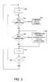
- FIG. 3is a flow chart of an example method in accordance with the invention.
- FIG. 4is a flow chart of an alternative example method in accordance with the invention.
- FIG. 5is a functional block diagram of example circuitry within a power supply in accordance with the invention.
- FIG. 1illustrates an example of a power supply system for which the invention is applicable.
- Power source 100may be an AC main or a DC source.
- FIG. 1depicts three of N+1 power supplies (generally identified by reference number 104 ), labeled A(0)-A(N). The outputs of all the power supplies 104 are connected in parallel (through isolation diodes) to a DC power bus 106 .
- DC power bus 106may have multiple DC voltages plus one or more reference potentials or ground.
- a controller 102discussed in more detail below, receives signals from the power supplies 104 and sends control signals to the power supplies 104 .
- the controllermay receive from each power supply, for example, a signal indicating whether the input voltage to the power supply is within a specified range, a signal indicating whether the output voltage is within a specified range, a signal indicating whether the output current for the power supply is within a specified range, and a signal indicating whether the temperature of the power supply is within a specified range.
- the power supplymay send numerical values to the controller.
- the controllermay control, for each power supply, for example, whether the power supply is in a standby mode or in a fully operational mode.
- the controllermay also receive information from the system being powered, for example a computer server system, regarding estimated current requirements.
- FIG. 2illustrates an alternative example of a power supply system for which the invention is applicable.
- Power sources 200 and 202could be, for example, two separate phases of a 3-phase AC power main, or one phase of an AC power main and the output of a local AC generator, or two separate isolated DC sources.
- FIG. 2depicts six of 2N+2 power supplies (generally identified by reference number 206 ), labeled A(0)-A(N) and B(0)-B(N). Power supplies A(0)-A(N) are connected to power source 200 , and power supplies B(0)-B(N) are connected to power source 202 .
- DC power bus 208may have multiple DC voltages plus one or more reference potentials or ground.
- a controller 204receives signals from the power supplies 206 , and sends control signals to the power supplies 206 .
- controller 204 in FIG. 2may receive from each power supply, for example, a signal indicating whether the input voltage to the power supply is within a specified range, a signal indicating whether the output voltage is within a specified range, a signal indicating whether the output current for the power supply is within a specified range, and a signal indicating whether the temperature of the power supply is within a specified range.
- the power supplymay send numerical values to the controller.
- the controllermay control, for each power supply, for example, whether the power supply is in a standby mode or in a fully operational mode.
- the maximum current required by the system (not illustrated), attached to the power bus 106can be supplied by, for example, N of the N+1 power supplies. If parts of the system do not require maximum current, then even fewer than N power supplies may supply the required current.
- the maximum current required by the system (not illustrated), attached to the power bus 208can be supplied by, for example, N of the 2N+2 power supplies. That is, for a system as in FIG.
- one power source( 200 or 202 ) can fail, and one of the N+1 power supplies attached to one power source can fail, and the remaining N operational power supplies can provide the maximum current required by the system.
- each individual power supplyis providing less than 50% of its maximum output current. For many power supply designs, this is a relatively low efficiency operating point. Accordingly, there is a need to be able have some of the power supplies operating at their point of maximum efficiency, and have the remaining power supplies in a standby mode, from which they can rapidly become fully operational when needed. Some power supplies may placed into standby mode if their output current falls below a threshold, for example, 75% of the maximum design current for one power supply.
- the thresholdmay vary depending on the number of power supplies, number of power sources, power supply efficiency characteristics, and other system parameters.
- FIG. 3illustrates one example of part of a method to reduce the number of operating power supplies to improve energy efficiency.
- the method in FIG. 3may be implemented by controller 102 in FIG. 1 or by controller 204 in FIG. 2 .
- the controllerrepeatedly polls the status of some of the individual power supplies.
- an indexis set to zero.
- the status of the output current for one power supply corresponding to the index value of step 300is read by the controller. If the output current for power supply A(i) is less than a low threshold, then at step 304 the controller commands power supply A(i) to switch to a standby mode.
- the controllercommands at least one standby power supply to switch to a fully operational mode.
- the controllermay track which power supplies are in standby mode, and the controller may use any method to select at least one power supply to switch to a fully operational mode. If a power source fails, or if there is any other indication that an increased load is need, then preferably all power supplies should be returned to the fully operational mode. After some specified time period, some power supplies could be returned to a standby mode.
- Polling by a controllermay add some delay in switching power supplies from standby to fully operational. Accordingly, it may be preferable for each supply to monitor current continuously, and inform the controller, for example by processor interrupt, immediately when current exceeds an upper threshold.
- An exampleis illustrated in FIG. 5 . Also, as will be discussed in conjunction with FIG. 5, instead of the controller commanding a power supply to switch to a fully operational mode, another power supply may signal a power supply to switch to a fully operational mode.
- the controllerincrements the index (step 310 ) and then repeats the procedure for the next power supply.
- FIG. 4illustrates an alternative method in which the current outputs of dual supplies are checked on each pass through the loop, and the controller may command power supplies on either power source to switch to standby.
- the controllerrepeatedly polls the status of some of the individual power supplies.
- an indexis set to zero.
- the status of the output current for one power supply corresponding to the index value of step 400is read by the controller. If the output current for power supply A(i) is less than a low threshold, then at step 404 the controller commands power supply A(i) to switch to a standby mode.
- the status of the output current for the other supply corresponding to the index value of step 400is read by the controller. If the output current for power supply B(i) is less than the low threshold, then at step 408 the controller commands power supply B(i) to switch to a standby mode.
- the equivalent of steps 306 and 308 of FIG. 3may optionally be performed in the method of FIG. 4, as discussed in conjunction with FIG. 3 .
- the controllermay then follow a method as illustrated in FIG. 3 or 4 to put power supplies, one at a time, into a standby mode, until the remaining operational power supplies all have output currents that exceed the lower threshold. If a particular power supply has an output current that is below the lower threshold, it is not necessary for the controller to command the particular power supply to switch to a standby mode.
- the controllermay switch power supplies to standby in a particular order, regardless of which power supplies are measured with low output current. For power supplies in pairs, the controller may switch both supplies in a pair to standby after detecting a low output current for only one power supply in the pair.
- each power supplycould provide a numerical output to the controller, indicating output current level, and the controller could compute how many power supplies should be placed into standby mode. The controller would then send commands to the appropriate number of power supplies, without executing a polling loop.
- FIG. 5illustrates an example of circuitry, inside a power supply, which might be used in conjunction with a standby command from a controller.
- the power supplyhas an input 500 for a standby command from a controller.
- the power supplymeasures its own output current (module 502 ).
- the measure of the output currentmay be represented as a voltage signal, but as discussed above, could also be numerical.
- an analog comparator 504compares a voltage signal, representing measured output current, to the upper reference voltage, and determines whether the output current exceeds the upper threshold for the power supply.
- the power supplysends an override signal 506 to the controller indicating that the power supply will override any standby signal. That is, the power supply will remain fully operational, even if commanded to switch to a standby mode.
- a second analog comparator 508determines whether the output current is less than the lower threshold. The output of comparator 508 is sent to the controller to indicate that the output current is low (FIG. 3, step 302 , FIG. 4, step 402 ).
- the output of the lower reference comparator 508is integrated over time (integrator 512 ). If the power supply is receiving a signal to switch to standby ( 500 ), and if the output of the integrator 512 indicates that the power supply has been operating with an output current that is less than the lower threshold for some extended time, then the power supply places itself into a standby mode (power supply internal control module 516 ). The time delay needs to be long enough to prevent noise and transients from inadvertently triggering a standby mode.
- each power supply in a pair of power suppliescould contain circuitry as illustrated in FIG. 5 .
- Signal 518 in FIG. 5is an optional input from the other power supply of a pair. For example, the output of the upper reference comparator in each B(i) power supply would go to the corresponding A(i) power supply as a standby override signal, and the output of the upper reference comparator in each A(i) power supply would go to the corresponding B(i) power supply as a standby override signal.
- the standby override signal from power supply B( 2 )would force power supply A( 2 ) to be in a fully operational mode, and power supply A( 2 ) would ignore any commands to switch to a standby mode.
- standby override signal from power supply B( 2 )would cause power supply A( 2 ) to switch to a fully operational mode.
- one power supply in a pairmay be in standby mode, and instead of the controller commanding the standby power supply to switch to fully operational mode, the corresponding power supply in the pair may signal the standby power supply to switch to a fully operational mode.
- a power source(FIG. 2, power source 200 or power source 202 ) should fail, or if a power supply should fail, at least one power supply needs to switch from standby mode to fully operational mode before the overall output bus current is affected.
- Power suppliestypically have some energy storage (in capacitors and/or inductors), so that full current can be provided for some period of time after the power source is off.
- Commercially available power suppliescan switch from standby mode to fully operational mode in 20 to 50 msec.
- the energy storage for power suppliescan be designed to provide more than 50 msec of full output current after loss of the power source, so that some power supplies can switch from standby to operational before the sourceless supplies stop supplying full output current.
- the integrator 512has a role in switching from fully operational mode to standby mode, but does not affect the time required to switch from standby mode to fully operational mode.
- Individual power suppliesmay include fans or other cooling means.
- the cooling meansshould also be turned off for further efficiency.
- a package of two power suppliescontains one cooling fan, it may be preferable to make fan control dependent on temperature.
- temperaturemay be measured within each package, with the measurement sent to the controller, and cooling may be controlled by the controller.
- a controllermay also turn some power supplies completely off (or offline), as opposed to just switching to a standby mode, further conserving energy.
- a rack or cabinetmay be provided that has the capability to hold many electronic devices, but may only be partially populated with electronic devices.
- some computer systemscomprise multiple printed circuit boards, where each circuit board is a separate computer.
- the rack or cabinetmay contain enough power supplies to provide power to a fully populated system.
- a controlleras depicted by FIG. 1, 102 and FIG. 2, 204 , may sense how many electronic devices are actually present, and instead of switching some power supplies to standby, may switch an appropriate number of power supplies completely off (or to an offline mode). For example, assume that a rack can accommodate four computers, and that ten power supplies are provided.
- signal 520depicts an input signal commanding a power supply to turn off (or go into an offline mode).
- Signal 520is depicted as an input to the control module 516 , but may go to some other part of a power supply as appropriate to implement the function. A power supply that is off, or offline, cannot be rapidly switched to a fully operational mode.
Landscapes
- Engineering & Computer Science (AREA)
- Power Engineering (AREA)
- Business, Economics & Management (AREA)
- Emergency Management (AREA)
- Direct Current Feeding And Distribution (AREA)
- Dc-Dc Converters (AREA)
Abstract
Description
This invention relates generally to power supplies for electronic systems.
Electronic equipment requires a source of electrical power. Typically, AC power is converted to at least one DC voltage at a level required by the electronic equipment. In large electronic systems, for example, telecommunications systems and large computer server systems, it is common to provide multiple power supplies, operating with outputs in parallel. It is also common to provide redundant power supplies to ensure continuous operation even with the failure of one or more power supplies. For example, in the telecommunications industry, if N power supplies are needed, it is common to use N+1 power supplies. It is also known to provide two separate sources of AC power, with separate banks of power supplies on each source of AC power, to ensure continuous operation even with the failure of one AC power source. For example, in large computer server systems, if N power supplies are needed, it is known to provide two different AC power sources with N+1 power supplies on each AC power source (2N+2 total power supplies with outputs in parallel). Alternatively, at least one isolated DC voltage may be distributed, and multiple local DC-to-DC converters may operate in parallel to provide the voltages and currents needed by each local system.
The number of power supplies operating with parallel outputs is typically determined by worst-case current load requirements. For example, if a system requires 100 amps maximum, and each power supply can provide 10 amps maximum, then at least 10 power supplies are connected to operate with outputs in parallel. If the actual current load is less than the worst-case current load, then each power supply provides some fraction of the maximum design current per power supply. Power supply redundancy may result in each power supply providing a relatively small fraction of the maximum design current per power supply. In general, within the designed range of output current, individual power supply efficiency improves with increasing output current. Power supply redundancy may result in each power supply operating at a reduced efficiency. For example, in a system with two power sources and 2N+2 power supplies, if both power sources are available, and if all power supplies are operational, then N+1 supplies are redundant, and each individual power supply is providing less than 50% of its maximum output current. There is a need for more efficient operation of power supplies configured with parallel outputs.
Output current is monitored for at least some power supplies. The number of power supplies providing current is then controlled to improve the overall system efficiency. For example, when the output current of one or more individual power supplies falls below a threshold, one or more power supplies may be placed into a standby mode. This increases the output current of the power supplies that are in an operational mode, improving their efficiency. If the current load increases, one or more supplies in standby mode can be rapidly switched to an operational mode. Optionally, a controller may also turn some power supplies completely off (or offline), as opposed to just switching to a standby mode, further conserving energy.
FIG. 1 is a block diagram of an example of a power supply system with a single power source in accordance with the invention.
FIG. 2 is a block diagram of an example of a power supply system with multiple power sources in accordance with the invention.
FIG. 3 is a flow chart of an example method in accordance with the invention.
FIG. 4 is a flow chart of an alternative example method in accordance with the invention.
FIG. 5 is a functional block diagram of example circuitry within a power supply in accordance with the invention.
FIG. 1 illustrates an example of a power supply system for which the invention is applicable. In the system illustrated in FIG. 1, there is asingle power source 100.Power source 100 may be an AC main or a DC source. FIG. 1 depicts three of N+1 power supplies (generally identified by reference number104), labeled A(0)-A(N). The outputs of all thepower supplies 104 are connected in parallel (through isolation diodes) to aDC power bus 106.DC power bus 106 may have multiple DC voltages plus one or more reference potentials or ground. Acontroller 102, discussed in more detail below, receives signals from thepower supplies 104 and sends control signals to thepower supplies 104. The controller may receive from each power supply, for example, a signal indicating whether the input voltage to the power supply is within a specified range, a signal indicating whether the output voltage is within a specified range, a signal indicating whether the output current for the power supply is within a specified range, and a signal indicating whether the temperature of the power supply is within a specified range. Alternatively, the power supply may send numerical values to the controller. The controller may control, for each power supply, for example, whether the power supply is in a standby mode or in a fully operational mode. The controller may also receive information from the system being powered, for example a computer server system, regarding estimated current requirements.
FIG. 2 illustrates an alternative example of a power supply system for which the invention is applicable. In the system illustrated in FIG. 2, there are twopower sources Power sources power source 200, and power supplies B(0)-B(N) are connected topower source 202. The outputs of all thepower supplies 102 are connected in parallel (through isolation diodes) to aDC power bus 208.DC power bus 208 may have multiple DC voltages plus one or more reference potentials or ground. Acontroller 204, discussed in more detail below, receives signals from thepower supplies 206, and sends control signals to thepower supplies 206. As discussed forcontroller 102 in FIG. 1,controller 204 in FIG. 2 may receive from each power supply, for example, a signal indicating whether the input voltage to the power supply is within a specified range, a signal indicating whether the output voltage is within a specified range, a signal indicating whether the output current for the power supply is within a specified range, and a signal indicating whether the temperature of the power supply is within a specified range. Alternatively, the power supply may send numerical values to the controller. The controller may control, for each power supply, for example, whether the power supply is in a standby mode or in a fully operational mode.
Energy efficiency is of particular interest in the present application. In general, within the designed range of output current, individual power supply efficiency improves with increasing output current. In a configuration as illustrated in FIG. 1, the maximum current required by the system (not illustrated), attached to thepower bus 106, can be supplied by, for example, N of the N+1 power supplies. If parts of the system do not require maximum current, then even fewer than N power supplies may supply the required current. In a configuration as illustrated in FIG. 2, the maximum current required by the system (not illustrated), attached to thepower bus 208, can be supplied by, for example, N of the 2N+2 power supplies. That is, for a system as in FIG. 2, one power source (200 or202) can fail, and one of the N+1 power supplies attached to one power source can fail, and the remaining N operational power supplies can provide the maximum current required by the system. In the system of FIG. 2, if bothpower sources
FIG. 3 illustrates one example of part of a method to reduce the number of operating power supplies to improve energy efficiency. The method in FIG. 3 may be implemented bycontroller 102 in FIG. 1 or bycontroller 204 in FIG.2. In the method of FIG. 3, the controller repeatedly polls the status of some of the individual power supplies. Atstep 300, an index is set to zero. Atstep 302, the status of the output current for one power supply corresponding to the index value ofstep 300 is read by the controller. If the output current for power supply A(i) is less than a low threshold, then atstep 304 the controller commands power supply A(i) to switch to a standby mode.
In the method illustrated in FIG. 3, atstep 306, if the output current for power supply A(i) is greater than a higher threshold, for example, 90% of maximum design current, then atstep 308 the controller commands at least one standby power supply to switch to a fully operational mode. The controller may track which power supplies are in standby mode, and the controller may use any method to select at least one power supply to switch to a fully operational mode. If a power source fails, or if there is any other indication that an increased load is need, then preferably all power supplies should be returned to the fully operational mode. After some specified time period, some power supplies could be returned to a standby mode.
Polling by a controller, as illustrated in FIG. 3, may add some delay in switching power supplies from standby to fully operational. Accordingly, it may be preferable for each supply to monitor current continuously, and inform the controller, for example by processor interrupt, immediately when current exceeds an upper threshold. An example is illustrated in FIG.5. Also, as will be discussed in conjunction with FIG. 5, instead of the controller commanding a power supply to switch to a fully operational mode, another power supply may signal a power supply to switch to a fully operational mode.
In the method of FIG. 3, when current tests are complete for power supply A(i), the controller increments the index (step310) and then repeats the procedure for the next power supply.
Note that the method of FIG. 3, for a dual power source system as in FIG. 2, the system may switch all the power supplies connected to power source200 (power supplies A(i)) to standby, leaving only the power supplies connected to power source202 (power supplies B(i)) fully operational. It may be preferable to leave some supplies operational on each power source. FIG. 4 illustrates an alternative method in which the current outputs of dual supplies are checked on each pass through the loop, and the controller may command power supplies on either power source to switch to standby.
In FIG. 4, as in FIG. 3, the controller repeatedly polls the status of some of the individual power supplies. Atstep 400, an index is set to zero. Atstep 402, the status of the output current for one power supply corresponding to the index value ofstep 400 is read by the controller. If the output current for power supply A(i) is less than a low threshold, then atstep 404 the controller commands power supply A(i) to switch to a standby mode. Atstep 406, the status of the output current for the other supply corresponding to the index value ofstep 400 is read by the controller. If the output current for power supply B(i) is less than the low threshold, then atstep 408 the controller commands power supply B(i) to switch to a standby mode. The equivalent ofsteps
When the system is first powered-on, all power supplies initially are in a fully operational mode. The controller may then follow a method as illustrated in FIG. 3 or4 to put power supplies, one at a time, into a standby mode, until the remaining operational power supplies all have output currents that exceed the lower threshold. If a particular power supply has an output current that is below the lower threshold, it is not necessary for the controller to command the particular power supply to switch to a standby mode. The controller may switch power supplies to standby in a particular order, regardless of which power supplies are measured with low output current. For power supplies in pairs, the controller may switch both supplies in a pair to standby after detecting a low output current for only one power supply in the pair. Alternatively, each power supply could provide a numerical output to the controller, indicating output current level, and the controller could compute how many power supplies should be placed into standby mode. The controller would then send commands to the appropriate number of power supplies, without executing a polling loop.
Preferably, the system should include some safeguards to prevent unintentional switching to standby, and to prevent continuous cycling between standby and full operation, and to prevent reaction to transient conditions. FIG. 5 illustrates an example of circuitry, inside a power supply, which might be used in conjunction with a standby command from a controller. In FIG. 5 there is an upper reference value, corresponding, for example, to 90% of maximum output current, and a lower reference value, corresponding, for example, to 75% of maximum output current. In FIG. 5, the power supply has aninput 500 for a standby command from a controller. The power supply measures its own output current (module502). As illustrated in FIG. 5, the measure of the output current may be represented as a voltage signal, but as discussed above, could also be numerical. In the example configuration illustrated in FIG. 5, ananalog comparator 504 compares a voltage signal, representing measured output current, to the upper reference voltage, and determines whether the output current exceeds the upper threshold for the power supply. In the example illustrated in FIG. 5, if the output current exceeds the upper threshold, the power supply sends anoverride signal 506 to the controller indicating that the power supply will override any standby signal. That is, the power supply will remain fully operational, even if commanded to switch to a standby mode. Asecond analog comparator 508 determines whether the output current is less than the lower threshold. The output ofcomparator 508 is sent to the controller to indicate that the output current is low (FIG. 3,step 302, FIG. 4, step402). The output of thelower reference comparator 508 is integrated over time (integrator512). If the power supply is receiving a signal to switch to standby (500), and if the output of theintegrator 512 indicates that the power supply has been operating with an output current that is less than the lower threshold for some extended time, then the power supply places itself into a standby mode (power supply internal control module516). The time delay needs to be long enough to prevent noise and transients from inadvertently triggering a standby mode.
For configurations with two power sources, as illustrated in FIG. 2, there are commercially available power supplies that are configured with a pair of power supplies in a single package. Optionally, each power supply in a pair of power supplies could contain circuitry as illustrated in FIG.5.Signal 518 in FIG. 5 is an optional input from the other power supply of a pair. For example, the output of the upper reference comparator in each B(i) power supply would go to the corresponding A(i) power supply as a standby override signal, and the output of the upper reference comparator in each A(i) power supply would go to the corresponding B(i) power supply as a standby override signal. Then, for example, if the output current of power supply B(2) exceeds the upper threshold, then the standby override signal from power supply B(2) would force power supply A(2) to be in a fully operational mode, and power supply A(2) would ignore any commands to switch to a standby mode. Optionally, if power supply A(2) is already in a standby mode, standby override signal from power supply B(2) would cause power supply A(2) to switch to a fully operational mode. Accordingly, for power supplies configured in pairs, one power supply in a pair may be in standby mode, and instead of the controller commanding the standby power supply to switch to fully operational mode, the corresponding power supply in the pair may signal the standby power supply to switch to a fully operational mode.
If a power source (FIG. 2,power source 200 or power source202) should fail, or if a power supply should fail, at least one power supply needs to switch from standby mode to fully operational mode before the overall output bus current is affected. Power supplies typically have some energy storage (in capacitors and/or inductors), so that full current can be provided for some period of time after the power source is off. Commercially available power supplies can switch from standby mode to fully operational mode in 20 to 50 msec. The energy storage for power supplies can be designed to provide more than 50 msec of full output current after loss of the power source, so that some power supplies can switch from standby to operational before the sourceless supplies stop supplying full output current. Note in FIG. 5 that theintegrator 512 has a role in switching from fully operational mode to standby mode, but does not affect the time required to switch from standby mode to fully operational mode.
Individual power supplies may include fans or other cooling means. Preferably, if a power supply is in standby mode, the cooling means should also be turned off for further efficiency. If a package of two power supplies contains one cooling fan, it may be preferable to make fan control dependent on temperature. Alternatively, temperature may be measured within each package, with the measurement sent to the controller, and cooling may be controlled by the controller.
Optionally, a controller may also turn some power supplies completely off (or offline), as opposed to just switching to a standby mode, further conserving energy. In some systems, a rack or cabinet may be provided that has the capability to hold many electronic devices, but may only be partially populated with electronic devices. For example, some computer systems comprise multiple printed circuit boards, where each circuit board is a separate computer. The rack or cabinet may contain enough power supplies to provide power to a fully populated system. A controller, as depicted by FIG. 1,102 and FIG. 2,204, may sense how many electronic devices are actually present, and instead of switching some power supplies to standby, may switch an appropriate number of power supplies completely off (or to an offline mode). For example, assume that a rack can accommodate four computers, and that ten power supplies are provided. If only two computers are actually installed, the power system controller may command five power supplies to turn off (or go into an offline mode). In FIG. 5, signal520 depicts an input signal commanding a power supply to turn off (or go into an offline mode).Signal 520 is depicted as an input to thecontrol module 516, but may go to some other part of a power supply as appropriate to implement the function. A power supply that is off, or offline, cannot be rapidly switched to a fully operational mode.
The foregoing description of the present invention has been presented for purposes of illustration and description. It is not intended to be exhaustive or to limit the invention to the precise form disclosed, and other modifications and variations may be possible in light of the above teachings. The embodiment was chosen and described in order to best explain the principles of the invention and its practical application to thereby enable others skilled in the art to best utilize the invention in various embodiments and various modifications as are suited to the particular use contemplated. It is intended that the appended claims be construed to include other alternative embodiments of the invention except insofar as limited by the prior art.
Claims (32)
1. An electronic system, comprising:
a plurality of power supplies; and
at least one power supply is switched to a standby mode when the output current of at least one power supply is less than a threshold.
2. The electronic system ofclaim 1 , further comprising:
a controller; and
the controller commands a particular power supply to switch to the standby mode when the particular power supply indicates, to the controller, that the output current of the particular power supply is less than the threshold.
3. The electronic system ofclaim 2 , further comprising:
at least one of the power supplies overriding a command from the controller to switch to the standby mode when the output current of the power supply exceeds a second threshold.
4. The electronic system ofclaim 2 , further comprising:
at least one of the power supplies switching to the standby mode in response to a command from the controller only when the output current of the power supply is less than the threshold for a period of time.
5. The electronic system ofclaim 2 , further comprising:
the power supplies configured into modules, each module comprising two power supplies; and
one power supply, in one of the modules, overriding a command from the controller to switch to the standby mode, in response to a signal from the other power supply in the module.
6. The electronic system ofclaim 1 , further comprising:
a controller that computes a number of power supplies to be switched to the standby mode; and
the controller commands the number of power supplies to switch to the standby mode.
7. The electronic system ofclaim 6 , further comprising:
at least one of the power supplies overriding a command from the controller to switch to the standby mode when the output current of the power supply exceeds a second threshold.
8. The electronic system ofclaim 6 , further comprising:
at least one of the power supplies switching to the standby mode in response to a command from the controller only when the output current of the power supply is less than the threshold for a period of time.
9. The electronic system ofclaim 6 , further comprising:
the controller computes a number of the power supplies to be switched to an off mode; and
the controller command the number of power supplies to switch to the off mode.
10. The electronic system ofclaim 1 , further comprising:
at least one power supply is switched from the standby mode to a fully operational mode when the output current of least one power supply is greater than a second threshold.
11. The electronic system ofclaim 10 , further comprising:
a controller;
at least one power supply switching from the standby mode to the fully operational mode in response to a command from the controller.
12. The electronic system ofclaim 10 , further comprising:
at least one power supply switching from the standby mode to the fully operational mode in response to a signal from one of the power supplies.
13. The electronic system ofclaim 10 , further comprising:
the power supplies configured into modules, each module comprising two power supplies; and
one power supply, in one of the modules, switching from the standby mode to the fully operational mode in response to a signal from the other power supply in the module.
14. The electronic system ofclaim 1 , further comprising:
first and second power sources, at least some of the power supplies coupled to the first power source and at least some of the power supplies coupled to the second power source, and where only power supplies coupled to one of the power sources is switched to the standby mode.
15. The electronic system ofclaim 1 , further comprising:
first and second power sources, at least some of the power supplies coupled to the first power source and at least some of the power supplies coupled to the second power source, and where at least one power supply coupled to the first power source and at least one power supply coupled to the second power source are switched to the standby mode.
16. The electronic system ofclaim 1 , further comprising:
at least one cooling fan; and
at least one cooling fan is switched off when at least one power supply is switched to a standby mode.
17. A method of controlling power supplies in an electronic system, comprising:
measuring current output from at least one of the power supplies;
switching at least one of the power supplies to a standby mode when its current output is less than a threshold.
18. The method ofclaim 17 , further comprising:
switching, to the standby mode, power supplies coupled to a first power source and not switching, to the standby mode, power supplies coupled to a second power source.
19. The method ofclaim 17 , further comprising:
switching, to the standby mode, at least one power supply coupled to a first power source and at least one power supply coupled to a second power source.
20. The method ofclaim 17 , further comprising:
switching at least one of the power supplies from the standby mode to a fully operational mode when at least one of the power supplies has an output current that exceeds a second threshold.
21. The method ofclaim 17 , further comprising:
receiving, by a controller, the measured output current; and
sending, by the controller, a command, to the power supply, to switch to the standby mode.
22. The method ofclaim 21 , further comprising:
switching, by the power supply, to the standby mode, in response to the command from the controller, only when the power supply output current is less than the threshold for a period of time.
23. The method ofclaim 17 , further comprising:
switching at least one cooling fan off for at least one of the power supplies that are switched to the standby mode.
24. A method of controlling power supplies in an electronic system, comprising:
determining, by a controller, that at least one of the power supplies has an output current that is less than a threshold; and
sending, by the controller, a command to at least one power supply to switch to a standby mode.
25. The method ofclaim 24 , further comprising:
computing, by the controller, a number of the power supplies to be switched to a standby mode; and
sending, by the controller, commands to the number of power supplies to switch to the standby mode.
26. The method ofclaim 24 , further comprising:
overriding, by a power supply, a command from the controller to switch to a standby mode, when the power supply output current exceeds a second threshold.
27. The method ofclaim 24 , further comprising:
overriding, by a power supply, a command from the controller to switch to a standby mode, when a corresponding power supply in a pair of power supplies has an output current that exceeds a second threshold.
28. The method ofclaim 24 , further comprising:
switching, by a power supply, to a standby mode, in response to a command from the controller, only when the output current of the power supply is less than the threshold for a time period.
29. The method ofclaim 24 , further comprising:
determining, by the controller, that at least one of the power supplies has an output current that is greater than a second threshold; and
sending, by the controller, a command to at least one power supply, to switch from a standby mode to a fully operational mode.
30. The method ofclaim 24 , further comprising:
switching, by a power supply, from a standby mode to a fully operational mode when a corresponding power supply in a pair of power supplies has an output current that exceeds a second threshold.
31. The method ofclaim 24 , further comprising:
sending, by the controller, a command to at least one power supply, to switch to an off state.
32. An electronic system, comprising:
means for measuring output current of power supplies; and
means for switching at least one of the power supplies to a standby mode when at least one the power supplies has an output current that is less than a threshold.
Priority Applications (2)
| Application Number | Priority Date | Filing Date | Title |
|---|---|---|---|
| US10/001,582US6614133B2 (en) | 2001-10-31 | 2001-10-31 | Power system with plural parallel power supplies with at least one power supply in standby mode for energy efficiency |
| JP2002311695AJP2003153438A (en) | 2001-10-31 | 2002-10-25 | Power system for controlling quantity of power supplies in complete operating condition for energy efficiency |
Applications Claiming Priority (1)
| Application Number | Priority Date | Filing Date | Title |
|---|---|---|---|
| US10/001,582US6614133B2 (en) | 2001-10-31 | 2001-10-31 | Power system with plural parallel power supplies with at least one power supply in standby mode for energy efficiency |
Publications (2)
| Publication Number | Publication Date |
|---|---|
| US20030080624A1 US20030080624A1 (en) | 2003-05-01 |
| US6614133B2true US6614133B2 (en) | 2003-09-02 |
Family
ID=21696805
Family Applications (1)
| Application Number | Title | Priority Date | Filing Date |
|---|---|---|---|
| US10/001,582Expired - LifetimeUS6614133B2 (en) | 2001-10-31 | 2001-10-31 | Power system with plural parallel power supplies with at least one power supply in standby mode for energy efficiency |
Country Status (2)
| Country | Link |
|---|---|
| US (1) | US6614133B2 (en) |
| JP (1) | JP2003153438A (en) |
Cited By (41)
| Publication number | Priority date | Publication date | Assignee | Title |
|---|---|---|---|---|
| US20030197428A1 (en)* | 2002-04-05 | 2003-10-23 | Hatton Thomas E. | Power processor |
| US20040003305A1 (en)* | 2002-06-28 | 2004-01-01 | Kabushiki Kaisha Toshiba | Information processing apparatus and power supply control method used in the apparatus |
| US20040124713A1 (en)* | 2002-12-04 | 2004-07-01 | Orr Raymond K. | Distributed power supply arrangement |
| WO2004032305A3 (en)* | 2002-09-30 | 2004-07-01 | Mrl Ind | Circuit and fault tolerant assembly including such circuit |
| US20040189249A1 (en)* | 2003-03-26 | 2004-09-30 | Pathfinder Energy Services, Inc. | Optimized battery life in multiple battery applications |
| US20050008146A1 (en)* | 2003-07-02 | 2005-01-13 | Chheda Sechin Navin | Apparatus and method for real-time power distribution management |
| US20050127884A1 (en)* | 2003-12-16 | 2005-06-16 | Harris Shaun L. | System and method for power distribution |
| US20060061921A1 (en)* | 2004-09-20 | 2006-03-23 | Tsung-Chun Chen | Control circuit and method of electric output modes |
| US20060163950A1 (en)* | 2005-01-25 | 2006-07-27 | Harris Shaun L | Converter to provide an output voltage for plural input voltages |
| US7157890B1 (en)* | 2005-10-25 | 2007-01-02 | Microchip Technology Inc. | Using pulse width modulation in the control of load sharing between paralleled power supplies |
| US20070075808A1 (en)* | 2005-10-05 | 2007-04-05 | Ls Industrial Systems Co., Ltd. | Multi-pole circuit breaker and apparatus for preventing deformation of driving shaft thereof |
| US20070204183A1 (en)* | 2006-02-24 | 2007-08-30 | Zippy Technology Corp. | Method and apparatus for processing abnormal conditions of a backup-type power supply system |
| US20070216229A1 (en)* | 2006-03-17 | 2007-09-20 | Johnson Robert W Jr | UPS methods, systems and computer program products providing adaptive availability |
| US20070285152A1 (en)* | 2006-06-12 | 2007-12-13 | Kabushiki Kaisha Toshiba | Power supply voltage controlling circuit and semiconductor integrated circuit |
| US20080077817A1 (en)* | 2006-09-26 | 2008-03-27 | Dell Products L.P. | Apparatus and Methods for Managing Power in an Information Handling System |
| US20080093933A1 (en)* | 2006-10-24 | 2008-04-24 | Kelly Jean Pracht | Systems and methods for providing redundant voltage regulation |
| US20090082910A1 (en)* | 2007-09-26 | 2009-03-26 | Oki Data Corporation | Information processing apparatus |
| US20090160259A1 (en)* | 2007-12-21 | 2009-06-25 | Wi-Chi, Inc. | Distributed Energy Conversion Systems |
| US20090225618A1 (en)* | 2008-03-05 | 2009-09-10 | Inventec Corporation | Power management module for memory module |
| US20090271642A1 (en)* | 2008-04-28 | 2009-10-29 | Delta Electronics, Inc. | Power management system capable of saving power and optimizing operating efficiency of power supplies for providing power with back-up or redundancy to plural loads |
| US20090309424A1 (en)* | 2008-06-12 | 2009-12-17 | Seiko Epson Corporation | Load driving circuit and load driving method |
| US20100067267A1 (en)* | 2008-09-17 | 2010-03-18 | Lineage Power Corporation | Controller and method for controlling converters of disparate type |
| US20100097044A1 (en)* | 2008-10-16 | 2010-04-22 | Gipson Kirk P | Power optimization of operating multiple power supplies |
| US20100157638A1 (en)* | 2008-12-20 | 2010-06-24 | Azuray Technologies, Inc. | Energy Conversion Systems With Power Control |
| US20100157632A1 (en)* | 2008-12-20 | 2010-06-24 | Azuray Technologies, Inc. | Energy Conversion Systems With Power Control |
| US20100164292A1 (en)* | 2008-12-30 | 2010-07-01 | International Business Machines Corporation | Apparatus, system, and method for reducing power consumption on devices with multiple power supplies |
| WO2010120316A1 (en)* | 2009-04-17 | 2010-10-21 | Lsi Corporation | Adaptation of an active power supply set using an event trigger |
| US20110025129A1 (en)* | 2009-07-29 | 2011-02-03 | Hewlett-Packard Development Company, L.P. | Redundant power supply systems and methods |
| US20110068634A1 (en)* | 2009-09-18 | 2011-03-24 | Power Distribution Inc. | Direct current power supply for mission critical applications |
| US20110205769A1 (en)* | 2010-02-19 | 2011-08-25 | International Business Machines Corporation | Power sharing method and system for two-stage power supplies |
| US8595521B2 (en)* | 2007-09-04 | 2013-11-26 | Juniper Networks, Inc. | Increasing mean time between failures for power supplies |
| US8890495B2 (en) | 2013-01-24 | 2014-11-18 | Freescale Semiconductor, Inc. | Power supply for integrated circuit |
| US20150346789A1 (en)* | 2014-05-29 | 2015-12-03 | International Business Machines Corporation | Power supply system for an information handling system and power supply method thereof |
| CN105162126A (en)* | 2015-08-24 | 2015-12-16 | 国电南瑞科技股份有限公司 | Regional voltage control method in local dispatching automatic voltage control (AVC) system |
| US20160049795A1 (en)* | 2014-08-14 | 2016-02-18 | Zodiac Aero Electric | Supply system for electronic boards of an electrical distribution system |
| US9755454B1 (en)* | 2013-03-28 | 2017-09-05 | Juniper Networks, Inc. | Methods and apparatus for providing redundant power supply protection with power zones for electronic devices |
| US9785127B2 (en) | 2013-07-02 | 2017-10-10 | Samsung Electronics Co., Ltd. | Power supply device, micro server having the same, and power supply method |
| US10516260B2 (en) | 2017-03-01 | 2019-12-24 | Hewlett Packard Enterprise Development Lp | Multi-node system fault management |
| US10886749B2 (en) | 2018-10-23 | 2021-01-05 | Hewlett Packard Enterprise Development Lp | Synchronized startup of power supplies in electrical systems |
| US11228202B2 (en) | 2019-02-06 | 2022-01-18 | Hewlett Packard Enterprise Development Lp | Synchronized standby startup of power supplies with current injection |
| US20230099662A1 (en)* | 2020-02-28 | 2023-03-30 | Nippon Telegraph And Telephone Corporation | Communication facilities power supply control device, power supply control method, power supply control program, and power supply control system |
Families Citing this family (17)
| Publication number | Priority date | Publication date | Assignee | Title |
|---|---|---|---|---|
| JP4696725B2 (en)* | 2005-06-29 | 2011-06-08 | 富士電機システムズ株式会社 | IC for switching power supply control |
| US7400110B2 (en)* | 2006-01-31 | 2008-07-15 | Honeywell International Inc. | Smart power converter |
| EP2088667A1 (en)* | 2008-02-06 | 2009-08-12 | EM Microelectronic-Marin SA | DC-DC converter for low-power electronic circuit |
| JP4600489B2 (en)* | 2008-02-21 | 2010-12-15 | 日本電気株式会社 | Power control device |
| AU2010326045A1 (en) | 2009-12-01 | 2012-07-26 | International Electrical Savings & Development, LLC | Systems and devices for reducing phantom load |
| US8352758B2 (en)* | 2010-03-22 | 2013-01-08 | International Business Machines Corporation | Power bus current bounding using local current-limiting soft-switches and device requirements information |
| JP5696887B2 (en)* | 2011-03-09 | 2015-04-08 | 日本電気株式会社 | Power control apparatus and power control method |
| JP5997700B2 (en) | 2011-09-29 | 2016-09-28 | レノボ・エンタープライズ・ソリューションズ(シンガポール)プライベート・リミテッド | Power supply device and control method thereof |
| DE102012102607B4 (en)* | 2012-03-27 | 2021-02-11 | Deutsche Telekom Ag | Method and arrangement for controlling the power supply and air conditioning elements for network elements of telecommunications networks with variable electrical loads |
| CN103809723A (en)* | 2012-11-15 | 2014-05-21 | 英业达科技有限公司 | Equipment cabinet and power source control method thereof |
| US9550421B2 (en)* | 2014-03-17 | 2017-01-24 | Denso International America, Inc. | DC-to-DC converter with variable set-point control |
| TWI596467B (en)* | 2014-07-11 | 2017-08-21 | 光寶科技股份有限公司 | Power supply system and control method thereof |
| JP6428338B2 (en)* | 2015-02-13 | 2018-11-28 | 富士通株式会社 | Power supply control device and power supply control program |
| US10199860B2 (en) | 2017-01-28 | 2019-02-05 | Microsoft Technology Licensing, Llc | Power supply recovery current history-based limitation |
| US10536004B2 (en)* | 2017-02-28 | 2020-01-14 | Raytheon Company | Autonomous system and method for redundancy management of multiple power supplies |
| CN111752767B (en)* | 2019-03-28 | 2025-02-11 | 杭州海康威视数字技术股份有限公司 | Electronic device and power supply control method and device thereof |
| US11239689B2 (en) | 2020-06-30 | 2022-02-01 | Cisco Technology, Inc. | Method and apparatus for efficient power delivery in power supply system |
Citations (10)
| Publication number | Priority date | Publication date | Assignee | Title |
|---|---|---|---|---|
| US4191992A (en)* | 1978-02-23 | 1980-03-04 | Megapulse Incorporated | Method of and apparatus for enabling soft-failure of modular power converter systems, including RF generator systems, embodying switching components in the power conversion |
| US4860188A (en)* | 1988-05-02 | 1989-08-22 | Texas Instruments Incorporated | Redundant power supply control |
| US5200643A (en)* | 1989-02-21 | 1993-04-06 | Westinghouse Electric Corp. | Parallel electric power supplies with current sharing and redundancy |
| US5266838A (en) | 1991-12-05 | 1993-11-30 | Thinking Machines Corporation | Power supply system including power sharing control arrangement |
| US5353215A (en)* | 1992-05-29 | 1994-10-04 | Thomson Consumer Electronics, Inc. | Tracking run/standby power supplies |
| US5675480A (en)* | 1996-05-29 | 1997-10-07 | Compaq Computer Corporation | Microprocessor control of parallel power supply systems |
| US5861684A (en) | 1995-12-27 | 1999-01-19 | Tandem Computers Incorporated | Flexible implementation of distributed DC power |
| US6297976B1 (en)* | 1999-04-23 | 2001-10-02 | Lg Electronics, Inc. | Thin, cascade-connected direct current source circuit |
| US6307762B1 (en)* | 1998-12-14 | 2001-10-23 | Sony Corporation | Power supplying circuit and method |
| US6414864B1 (en)* | 1999-11-11 | 2002-07-02 | Lg Electronics Inc. | Circuit for reducing standby power of electric apparatus |
- 2001
- 2001-10-31USUS10/001,582patent/US6614133B2/ennot_activeExpired - Lifetime
- 2002
- 2002-10-25JPJP2002311695Apatent/JP2003153438A/enactivePending
Patent Citations (10)
| Publication number | Priority date | Publication date | Assignee | Title |
|---|---|---|---|---|
| US4191992A (en)* | 1978-02-23 | 1980-03-04 | Megapulse Incorporated | Method of and apparatus for enabling soft-failure of modular power converter systems, including RF generator systems, embodying switching components in the power conversion |
| US4860188A (en)* | 1988-05-02 | 1989-08-22 | Texas Instruments Incorporated | Redundant power supply control |
| US5200643A (en)* | 1989-02-21 | 1993-04-06 | Westinghouse Electric Corp. | Parallel electric power supplies with current sharing and redundancy |
| US5266838A (en) | 1991-12-05 | 1993-11-30 | Thinking Machines Corporation | Power supply system including power sharing control arrangement |
| US5353215A (en)* | 1992-05-29 | 1994-10-04 | Thomson Consumer Electronics, Inc. | Tracking run/standby power supplies |
| US5861684A (en) | 1995-12-27 | 1999-01-19 | Tandem Computers Incorporated | Flexible implementation of distributed DC power |
| US5675480A (en)* | 1996-05-29 | 1997-10-07 | Compaq Computer Corporation | Microprocessor control of parallel power supply systems |
| US6307762B1 (en)* | 1998-12-14 | 2001-10-23 | Sony Corporation | Power supplying circuit and method |
| US6297976B1 (en)* | 1999-04-23 | 2001-10-02 | Lg Electronics, Inc. | Thin, cascade-connected direct current source circuit |
| US6414864B1 (en)* | 1999-11-11 | 2002-07-02 | Lg Electronics Inc. | Circuit for reducing standby power of electric apparatus |
Cited By (78)
| Publication number | Priority date | Publication date | Assignee | Title |
|---|---|---|---|---|
| US20030197428A1 (en)* | 2002-04-05 | 2003-10-23 | Hatton Thomas E. | Power processor |
| US7043648B2 (en)* | 2002-06-28 | 2006-05-09 | Kabushiki Kaisha Toshiba | Multiprocessor power supply system that operates a portion of available power supplies and selects voltage monitor point according to the number of detected processors |
| US20040003305A1 (en)* | 2002-06-28 | 2004-01-01 | Kabushiki Kaisha Toshiba | Information processing apparatus and power supply control method used in the apparatus |
| US7368832B2 (en) | 2002-09-30 | 2008-05-06 | Mrl Industries | Circuit and fault tolerant assembly including such circuit |
| WO2004032305A3 (en)* | 2002-09-30 | 2004-07-01 | Mrl Ind | Circuit and fault tolerant assembly including such circuit |
| US20040130920A1 (en)* | 2002-09-30 | 2004-07-08 | Kevin Peck | Circuit and fault tolerant assembly including such circuit |
| US20100038967A1 (en)* | 2002-12-04 | 2010-02-18 | Orr Raymond K | Distributed power supply arrangement |
| US7622824B2 (en)* | 2002-12-04 | 2009-11-24 | Orr Raymond K | Distributed power supply arrangement |
| US7936088B2 (en) | 2002-12-04 | 2011-05-03 | Power Integrations, Inc. | Distributed power supply arrangement |
| US20040124713A1 (en)* | 2002-12-04 | 2004-07-01 | Orr Raymond K. | Distributed power supply arrangement |
| US7009363B2 (en) | 2003-03-26 | 2006-03-07 | Pathfinder Energy Services, Inc. | Optimized battery life in multiple battery applications |
| US20040189249A1 (en)* | 2003-03-26 | 2004-09-30 | Pathfinder Energy Services, Inc. | Optimized battery life in multiple battery applications |
| US20050008146A1 (en)* | 2003-07-02 | 2005-01-13 | Chheda Sechin Navin | Apparatus and method for real-time power distribution management |
| US7436950B2 (en) | 2003-07-02 | 2008-10-14 | Hewlett-Packard Development Company, L.P. | Apparatus and method for real-time power distribution management |
| US20050127884A1 (en)* | 2003-12-16 | 2005-06-16 | Harris Shaun L. | System and method for power distribution |
| US7082042B2 (en) | 2003-12-16 | 2006-07-25 | Hewlett-Packard Development Company, L.P. | System and method for power distribution |
| US7443053B2 (en)* | 2004-09-20 | 2008-10-28 | Zippy Technology Corp. | Control circuit and method of electric output modes |
| US20060061921A1 (en)* | 2004-09-20 | 2006-03-23 | Tsung-Chun Chen | Control circuit and method of electric output modes |
| US7345381B2 (en) | 2005-01-25 | 2008-03-18 | Hewlett-Packard Development Company, L.P. | Converter to provide an output voltage for plural input voltages |
| US20060163950A1 (en)* | 2005-01-25 | 2006-07-27 | Harris Shaun L | Converter to provide an output voltage for plural input voltages |
| US20070075808A1 (en)* | 2005-10-05 | 2007-04-05 | Ls Industrial Systems Co., Ltd. | Multi-pole circuit breaker and apparatus for preventing deformation of driving shaft thereof |
| US7157890B1 (en)* | 2005-10-25 | 2007-01-02 | Microchip Technology Inc. | Using pulse width modulation in the control of load sharing between paralleled power supplies |
| US20070204183A1 (en)* | 2006-02-24 | 2007-08-30 | Zippy Technology Corp. | Method and apparatus for processing abnormal conditions of a backup-type power supply system |
| US20070216229A1 (en)* | 2006-03-17 | 2007-09-20 | Johnson Robert W Jr | UPS methods, systems and computer program products providing adaptive availability |
| US20070285152A1 (en)* | 2006-06-12 | 2007-12-13 | Kabushiki Kaisha Toshiba | Power supply voltage controlling circuit and semiconductor integrated circuit |
| US7586364B2 (en) | 2006-06-12 | 2009-09-08 | Kabushiki Kaisha Toshiba | Power supply voltage controlling circuit and semiconductor integrated circuit |
| US20080077817A1 (en)* | 2006-09-26 | 2008-03-27 | Dell Products L.P. | Apparatus and Methods for Managing Power in an Information Handling System |
| US7831843B2 (en) | 2006-09-26 | 2010-11-09 | Dell Products L.P. | Apparatus and methods for managing power in an information handling system |
| US7443055B2 (en)* | 2006-10-24 | 2008-10-28 | Hewlett-Packard Development Company, L.P. | Systems and methods for providing redundant voltage regulation |
| US20080093933A1 (en)* | 2006-10-24 | 2008-04-24 | Kelly Jean Pracht | Systems and methods for providing redundant voltage regulation |
| US8595521B2 (en)* | 2007-09-04 | 2013-11-26 | Juniper Networks, Inc. | Increasing mean time between failures for power supplies |
| US8193663B2 (en)* | 2007-09-26 | 2012-06-05 | Oki Data Corporation | Information processing apparatus with multiple power receiving units |
| US20090082910A1 (en)* | 2007-09-26 | 2009-03-26 | Oki Data Corporation | Information processing apparatus |
| US9263895B2 (en) | 2007-12-21 | 2016-02-16 | Sunpower Corporation | Distributed energy conversion systems |
| US20090160259A1 (en)* | 2007-12-21 | 2009-06-25 | Wi-Chi, Inc. | Distributed Energy Conversion Systems |
| US11527964B2 (en) | 2007-12-21 | 2022-12-13 | Enphase Energy, Inc. | Distributed energy conversion systems |
| US9608448B2 (en) | 2007-12-21 | 2017-03-28 | Sunpower Corporation | Distributed energy conversion systems |
| US20090225618A1 (en)* | 2008-03-05 | 2009-09-10 | Inventec Corporation | Power management module for memory module |
| US20090271642A1 (en)* | 2008-04-28 | 2009-10-29 | Delta Electronics, Inc. | Power management system capable of saving power and optimizing operating efficiency of power supplies for providing power with back-up or redundancy to plural loads |
| US8261102B2 (en)* | 2008-04-28 | 2012-09-04 | Delta Electronics, Inc. | Power management system capable of saving power and optimizing operating efficiency of power supplies for providing power with back-up or redundancy to plural loads |
| US8423806B2 (en) | 2008-04-28 | 2013-04-16 | Delta Electronics, Inc. | Power management system capable of saving power and optimizing operating efficiency of power supplies for providing power with back-up or redundancy to plural loads |
| US20090309424A1 (en)* | 2008-06-12 | 2009-12-17 | Seiko Epson Corporation | Load driving circuit and load driving method |
| US9250641B2 (en) | 2008-06-12 | 2016-02-02 | Seiko Epson Corporation | Load driving circuit and load driving method |
| US8049368B2 (en)* | 2008-06-12 | 2011-11-01 | Seiko Epson Corporation | Load driving circuit and load driving method |
| US20100067267A1 (en)* | 2008-09-17 | 2010-03-18 | Lineage Power Corporation | Controller and method for controlling converters of disparate type |
| US8150540B2 (en)* | 2008-09-17 | 2012-04-03 | Lineage Power Corporation | Controller and method for controlling converters of disparate type |
| US20100097044A1 (en)* | 2008-10-16 | 2010-04-22 | Gipson Kirk P | Power optimization of operating multiple power supplies |
| US8796884B2 (en) | 2008-12-20 | 2014-08-05 | Solarbridge Technologies, Inc. | Energy conversion systems with power control |
| US20100157632A1 (en)* | 2008-12-20 | 2010-06-24 | Azuray Technologies, Inc. | Energy Conversion Systems With Power Control |
| US20100157638A1 (en)* | 2008-12-20 | 2010-06-24 | Azuray Technologies, Inc. | Energy Conversion Systems With Power Control |
| US20100164292A1 (en)* | 2008-12-30 | 2010-07-01 | International Business Machines Corporation | Apparatus, system, and method for reducing power consumption on devices with multiple power supplies |
| US7906871B2 (en)* | 2008-12-30 | 2011-03-15 | International Business Machines Corporation | Apparatus, system, and method for reducing power consumption on devices with multiple power supplies |
| WO2010120316A1 (en)* | 2009-04-17 | 2010-10-21 | Lsi Corporation | Adaptation of an active power supply set using an event trigger |
| CN102301555A (en)* | 2009-04-17 | 2011-12-28 | Lsi公司 | Adaptation Of An Active Power Supply Set Using An Event Trigger |
| CN102301555B (en)* | 2009-04-17 | 2014-09-03 | Lsi公司 | Running Power Groups with Event-Triggered Debugging |
| US20110025129A1 (en)* | 2009-07-29 | 2011-02-03 | Hewlett-Packard Development Company, L.P. | Redundant power supply systems and methods |
| US8067857B2 (en) | 2009-07-29 | 2011-11-29 | Hewlett-Packard Development Company, L.P. | Redundant power supply systems and methods |
| US9098276B2 (en) | 2009-07-29 | 2015-08-04 | Hewlett-Packard Development Company, L.P. | Redundant power supply systems and methods |
| US8325504B2 (en) | 2009-09-18 | 2012-12-04 | Power Distribution, Inc. | Direct current power supply for mission critical applications |
| US20110068634A1 (en)* | 2009-09-18 | 2011-03-24 | Power Distribution Inc. | Direct current power supply for mission critical applications |
| US20110205769A1 (en)* | 2010-02-19 | 2011-08-25 | International Business Machines Corporation | Power sharing method and system for two-stage power supplies |
| US8400795B2 (en) | 2010-02-19 | 2013-03-19 | International Business Machines Corporation | Power sharing method and system for two-stage power supplies |
| US8890495B2 (en) | 2013-01-24 | 2014-11-18 | Freescale Semiconductor, Inc. | Power supply for integrated circuit |
| US10498165B1 (en)* | 2013-03-28 | 2019-12-03 | Juniper Networks, Inc. | Methods and apparatus for providing redundant power supply protection with power zones for electronic devices |
| US9755454B1 (en)* | 2013-03-28 | 2017-09-05 | Juniper Networks, Inc. | Methods and apparatus for providing redundant power supply protection with power zones for electronic devices |
| US9785127B2 (en) | 2013-07-02 | 2017-10-10 | Samsung Electronics Co., Ltd. | Power supply device, micro server having the same, and power supply method |
| US20150346789A1 (en)* | 2014-05-29 | 2015-12-03 | International Business Machines Corporation | Power supply system for an information handling system and power supply method thereof |
| US9658667B2 (en)* | 2014-05-29 | 2017-05-23 | International Business Machines Corporation | Power supply system for an information handling system |
| US20160049795A1 (en)* | 2014-08-14 | 2016-02-18 | Zodiac Aero Electric | Supply system for electronic boards of an electrical distribution system |
| US10263431B2 (en)* | 2014-08-14 | 2019-04-16 | Zodiac Aero Electric | Supply system for electronic boards of an electrical distribution system |
| CN105375610B (en)* | 2014-08-14 | 2019-08-02 | Zodiac航空电器 | The power supply system of the circuit board of distribution system |
| CN105375610A (en)* | 2014-08-14 | 2016-03-02 | Zodiac航空电器 | Supply system for electronic boards of an electrical distribution system |
| CN105162126A (en)* | 2015-08-24 | 2015-12-16 | 国电南瑞科技股份有限公司 | Regional voltage control method in local dispatching automatic voltage control (AVC) system |
| US10516260B2 (en) | 2017-03-01 | 2019-12-24 | Hewlett Packard Enterprise Development Lp | Multi-node system fault management |
| US10886749B2 (en) | 2018-10-23 | 2021-01-05 | Hewlett Packard Enterprise Development Lp | Synchronized startup of power supplies in electrical systems |
| US11228202B2 (en) | 2019-02-06 | 2022-01-18 | Hewlett Packard Enterprise Development Lp | Synchronized standby startup of power supplies with current injection |
| US20230099662A1 (en)* | 2020-02-28 | 2023-03-30 | Nippon Telegraph And Telephone Corporation | Communication facilities power supply control device, power supply control method, power supply control program, and power supply control system |
| US12062936B2 (en)* | 2020-02-28 | 2024-08-13 | Nippon Telegraph And Telephone Corporation | Controlling power supply from an electric power source to communication facilities in a communication system |
Also Published As
| Publication number | Publication date |
|---|---|
| US20030080624A1 (en) | 2003-05-01 |
| JP2003153438A (en) | 2003-05-23 |
Similar Documents
| Publication | Publication Date | Title |
|---|---|---|
| US6614133B2 (en) | Power system with plural parallel power supplies with at least one power supply in standby mode for energy efficiency | |
| EP2036189B1 (en) | Data center uninterruptible power distribution architecture | |
| CN101053138B (en) | Device and method for providing uninterruptible power supply | |
| US11431244B2 (en) | Power management circuit, capacitor management circuit and capacitor management method thereof | |
| EP2333930A2 (en) | Server and uninterruptable power supply housed in that server | |
| WO2010076076A1 (en) | Reducing power consumption on devices with multiple power supplies | |
| US7825536B2 (en) | Intelligent power system | |
| WO2009046533A1 (en) | Autonomous hybrid renewable energy controller | |
| JPH10201090A (en) | Power unit | |
| US9032250B1 (en) | Online testing of secondary power unit | |
| US11955607B2 (en) | Monitoring system for an energy storage | |
| US20220004239A1 (en) | Enhanced battery backup unit battery management system | |
| CN114637357B (en) | Fault detection method, controller, bypass voltage stabilizing circuit and storage medium | |
| EP2282393A1 (en) | Method and apparatus for providing uninterruptible power | |
| US20080186741A1 (en) | Method and system adapted to regenerate load energy in ac-to-dc and dc-to-ac power converter systems | |
| US11283286B2 (en) | Uninterruptible power supply | |
| Kuroda et al. | High-efficiency power supply system for server machines in data center | |
| US12418169B2 (en) | Direct current/direct current converter and control method thereof | |
| CN110768324A (en) | Distributed power supply system for ship, control method and storage medium | |
| CN114791762B (en) | Renewable energy system based on current detection for data center | |
| CN113970964B (en) | Method, system, equipment and storage medium for detecting power failure of power supply output of server | |
| US20250300490A1 (en) | Power supply switching system and switch apparatus | |
| CN118971320A (en) | Power supply cabinet power supply method, system, storage medium and intelligent terminal | |
| KR102463680B1 (en) | adaptive battery charging system by use of DC power load | |
| US20250271924A1 (en) | Electric energy management device, electric energy management system and electric energy management method for controlling current balance |
Legal Events
| Date | Code | Title | Description |
|---|---|---|---|
| AS | Assignment | Owner name:HEWLETT-PACKARD COMPANY, COLORADO Free format text:ASSIGNMENT OF ASSIGNORS INTEREST;ASSIGNORS:BELSON, STEVE;HARRIS, SHAUN L.;REEL/FRAME:012728/0225 Effective date:20020109 | |
| AS | Assignment | Owner name:HEWLETT-PACKARD DEVELOPMENT COMPANY, L.P., TEXAS Free format text:ASSIGNMENT OF ASSIGNORS INTEREST;ASSIGNOR:HEWLETT-PACKARD COMPANY;REEL/FRAME:013862/0623 Effective date:20030728 | |
| STCF | Information on status: patent grant | Free format text:PATENTED CASE | |
| FPAY | Fee payment | Year of fee payment:4 | |
| FPAY | Fee payment | Year of fee payment:8 | |
| FPAY | Fee payment | Year of fee payment:12 | |
| AS | Assignment | Owner name:HEWLETT PACKARD ENTERPRISE DEVELOPMENT LP, TEXAS Free format text:ASSIGNMENT OF ASSIGNORS INTEREST;ASSIGNOR:HEWLETT-PACKARD DEVELOPMENT COMPANY, L.P.;REEL/FRAME:037079/0001 Effective date:20151027 |