US6614008B2 - Universal voltage fuser heater lamp - Google Patents
Universal voltage fuser heater lampDownload PDFInfo
- Publication number
- US6614008B2 US6614008B2US10/014,451US1445101AUS6614008B2US 6614008 B2US6614008 B2US 6614008B2US 1445101 AUS1445101 AUS 1445101AUS 6614008 B2US6614008 B2US 6614008B2
- Authority
- US
- United States
- Prior art keywords
- lamp
- voltage
- fuser
- filaments
- heater lamp
- Prior art date
- Legal status (The legal status is an assumption and is not a legal conclusion. Google has not performed a legal analysis and makes no representation as to the accuracy of the status listed.)
- Expired - Lifetime, expires
Links
- 230000007246mechanismEffects0.000claimsabstractdescription22
- 230000009977dual effectEffects0.000claimsdescription4
- WABPQHHGFIMREM-UHFFFAOYSA-Nlead(0)Chemical compound[Pb]WABPQHHGFIMREM-UHFFFAOYSA-N0.000description12
- 239000004020conductorSubstances0.000description9
- VYPSYNLAJGMNEJ-UHFFFAOYSA-Nsilicon dioxideInorganic materialsO=[Si]=OVYPSYNLAJGMNEJ-UHFFFAOYSA-N0.000description7
- 239000010453quartzSubstances0.000description4
- 239000011888foilSubstances0.000description3
- 238000010438heat treatmentMethods0.000description3
- 239000000463materialSubstances0.000description3
- XKRFYHLGVUSROY-UHFFFAOYSA-NArgonChemical compound[Ar]XKRFYHLGVUSROY-UHFFFAOYSA-N0.000description2
- GZUXJHMPEANEGY-UHFFFAOYSA-NbromomethaneChemical compoundBrCGZUXJHMPEANEGY-UHFFFAOYSA-N0.000description2
- 239000000919ceramicSubstances0.000description2
- 239000005350fused silica glassSubstances0.000description2
- 239000007789gasSubstances0.000description2
- 229910052736halogenInorganic materials0.000description2
- 239000011261inert gasSubstances0.000description2
- 238000002844meltingMethods0.000description2
- 230000008018meltingEffects0.000description2
- 239000000203mixtureSubstances0.000description2
- 230000004048modificationEffects0.000description2
- 238000012986modificationMethods0.000description2
- WKBOTKDWSSQWDR-UHFFFAOYSA-NBromine atomChemical compound[Br]WKBOTKDWSSQWDR-UHFFFAOYSA-N0.000description1
- 239000004809TeflonSubstances0.000description1
- 229920006362Teflon®Polymers0.000description1
- 230000004913activationEffects0.000description1
- 229910052786argonInorganic materials0.000description1
- GDTBXPJZTBHREO-UHFFFAOYSA-NbromineSubstancesBrBrGDTBXPJZTBHREO-UHFFFAOYSA-N0.000description1
- 229910052794bromiumInorganic materials0.000description1
- 238000010276constructionMethods0.000description1
- 230000000694effectsEffects0.000description1
- 150000004820halidesChemical class0.000description1
- 150000002367halogensChemical class0.000description1
- 238000000034methodMethods0.000description1
- 229940102396methyl bromideDrugs0.000description1
- 230000008569processEffects0.000description1
- WFKWXMTUELFFGS-UHFFFAOYSA-NtungstenChemical compound[W]WFKWXMTUELFFGS-UHFFFAOYSA-N0.000description1
- 229910052721tungstenInorganic materials0.000description1
- 239000010937tungstenSubstances0.000description1
Images


Classifications
- H—ELECTRICITY
- H05—ELECTRIC TECHNIQUES NOT OTHERWISE PROVIDED FOR
- H05B—ELECTRIC HEATING; ELECTRIC LIGHT SOURCES NOT OTHERWISE PROVIDED FOR; CIRCUIT ARRANGEMENTS FOR ELECTRIC LIGHT SOURCES, IN GENERAL
- H05B1/00—Details of electric heating devices
- H05B1/02—Automatic switching arrangements specially adapted to apparatus ; Control of heating devices
- H05B1/0227—Applications
- H05B1/023—Industrial applications
- H05B1/0241—For photocopiers
- G—PHYSICS
- G03—PHOTOGRAPHY; CINEMATOGRAPHY; ANALOGOUS TECHNIQUES USING WAVES OTHER THAN OPTICAL WAVES; ELECTROGRAPHY; HOLOGRAPHY
- G03G—ELECTROGRAPHY; ELECTROPHOTOGRAPHY; MAGNETOGRAPHY
- G03G15/00—Apparatus for electrographic processes using a charge pattern
- G03G15/20—Apparatus for electrographic processes using a charge pattern for fixing, e.g. by using heat
- G03G15/2003—Apparatus for electrographic processes using a charge pattern for fixing, e.g. by using heat using heat
- H—ELECTRICITY
- H05—ELECTRIC TECHNIQUES NOT OTHERWISE PROVIDED FOR
- H05B—ELECTRIC HEATING; ELECTRIC LIGHT SOURCES NOT OTHERWISE PROVIDED FOR; CIRCUIT ARRANGEMENTS FOR ELECTRIC LIGHT SOURCES, IN GENERAL
- H05B3/00—Ohmic-resistance heating
- H05B3/0033—Heating devices using lamps
- H05B3/0038—Heating devices using lamps for industrial applications
- H05B3/0066—Heating devices using lamps for industrial applications for photocopying
Definitions
- the present inventionrelates generally to tubular incandescent lamps, and pertains, more particularly, to such lamps as applied in photo-reproduction processes.
- a photocopy machinetypically employs two different types of lamps, one being referred to as an exposure lamp and the other as a fusing lamp.
- the exposure lampis purely for light emitting purposes during the exposure phase of operation.
- the fusing lampon the other hand is primarily for heating purposes to “set” the toner employed in the photocopy machine.
- the principles thereofare applied primarily in connection with a fusing heater lamp, but may also be applied to other general heating purposes.
- Fusing heater lampsare typically of single filament construction and have a length corresponding to the maximum size (length) of paper that is to be reproduced. More recently, fusing heater lamps utilize two filaments disposed and electrically connected in parallel within a quartz envelope in order to allow substantially higher operating wattage to be achieved by simultaneously energizing both filaments. The use of parallel filaments provides higher heat density per unit area of envelope wall. However, these types of fuser heater lamps do not provide for selective activation of the filaments to adjust for different voltage output requirements.
- Photocopier's used in both the United States and Europeoperate at two different voltage ranges, namely 120 and 240 volts respectively, but each require the same amount of energy in the fuser lamp for fixing the toner (i.e. fusing) onto the copy of the original document.
- U.S. Pat. No. 4,710,676 to Morris et ala dual length filament incandescent lamp is provided that allows for switching between two different levels of total lamp energy at a single voltage to adjust for different incremental wattage output requirements.
- the specification of Morris et al(U.S. Pat. No. 4,710,676) is hereby incorporated by reference.
- a fuser lampcomprising first and second filaments having equal resistance and a switching mechanism for connecting a power supply to the fuser lamp.
- the switching mechanismconnects the first and second filaments in a parallel configuration when the voltage is 120 Volts and connects the first and second filaments in series when the voltage is 240 Volts from the power supply.
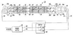
- FIG. 1is a side view, partly in section of a lamp illustrating the electrical switching control of the instant invention.
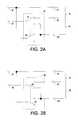
- FIGS. 2A-2Bis an electrical circuit schematic illustrating switch states of the instant invention.
- FIGS. 3A-3Care side views, partly in section, illustrating different lamp configuration embodiments for use with the electrical switching control of the instant invention.
- FIG. 1there is shown a side view, partly in section of a fuser lamp 10 illustrating the electrical switching control or switching mechanism of the instant invention.
- the electrical switching control or switch mechanismis a double-pole double-throw switch 40 defining a pair of first and second switches.
- a power supply 38delivers voltage to the fuser lamp 10 through the switch 40 .
- the lamp 10comprises a tubular envelope 12 of vitreous material having first and second press-sealed end portions 14 and 16 , respectively. Ends 14 and 16 are located at the opposed ends of envelope 12 and are formed by utilizing pressing operations and apparatus known in the art.
- Envelope 12should preferably be made of a material having a high melting point, such as fused silica or quartz.
- Lamp 10is of the tungsten-halogen variety, therefore it has a fill gas mixture containing an inert gas and a halogen or halide.
- the lampsare filled at about one atmosphere of argon (as the inert gas) and have about 200 micrograms of bromine (specifically methyl bromide).
- Lamp 10further includes a pair of tungsten filaments, 18 and 20 , which are disposed within envelope 12 and extend longitudinally through the interior of the envelope. Filaments 18 and 20 , as illustrated in FIG. 1, are electrically isolated from one another by isolating means, comprising two tubes, 22 and 24 , that are disposed longitudinally within envelope 12 . Filaments 18 and 20 extend longitudinally through tubes 22 and 24 , respectively.
- Tubes 22 and 24should be made of electrically insulative material that is transparent and has a high melting point, such as quartz. Tubes 22 and 24 extend the length of the interior of envelope 12 to about 1 millimeter (mm) from press sealed end portions 14 and 16 . The filaments are also hermetically sealed within end portions 14 and 16 .
- Supporting filaments 18 and 20 at preselected points (about 25.4 mm apart) along the length thereofare a plurality of support members 26 (illustrated in FIG. 1 ), each comprising a coil element having one end wound about (and thus secured to) each of filaments 18 and 20 and the other end (of greater diameter) positively engaging the interior wall of tubes 22 and 24 , respectively.
- filaments 18 and 20possessed an overall length of about 350 mm.
- envelope 12is a T-5 quartz tube having an outer diameter of about 15 mm with a thickness of about 1 mm.
- Tubes 22 and 24are T-2 quartz tubes having outer diameters of about 6 mm and thicknesses of about 1 mm.
- Ceramic bases 28 and 30are preferably used. Accordingly, it is only necessary in the respective photocopier to provide some means for accepting this component. Understandably, such a means can be of relatively simple design. Ceramic bases 28 and 30 are also preferably of substantially cylindrical configuration and include a slot therein designed for having the flattened press-sealed end portions, 14 and 16 , inserted therein.
- Filaments 18 and 20are energized by means of applying a predetermined voltage across contact means located within the press sealed end portions of lamp 10 .
- first contact means 32is associated with end portion 14
- second contact means 34 and third contact means 36are associated with end portion 16
- First contact means 32is comprised of a first lead-in conductor 32 a, which extends externally from and internally within end portion 14 , and a foil portion 32 b disposed within portion 14 and electrically coupled to both conductor 32 a and to a first end 18 a and 20 a of filaments 18 and 20 , respectively.
- Second contact means 34is comprised of a second lead-in conductor 34 a, which extends externally from and internally within end portion 16 , and a foil portion 34 b disposed within portion 16 and electrically coupled to both conductor 34 b and to a second end 18 b of filament 18 .
- third contact means 36is comprised of a third lead-in conductor 36 a, extending externally from and internally within end portion 16 , and a foil portion 36 b disposed within end portion 16 and electrically coupled to both conductor 36 a and to an unattached second end 20 b of filament 20 .
- the terminals 56 and 58 of power supply 38are coupled to the input side of first and second switches 66 and 68 respectively, of the double-pole double-throw switch 40 .
- Lead-in conductor 32is coupled to a lead wire 50 , which is in turn coupled to the output side of first switch 66 .
- Lead-in conductor 34is coupled to a lead wire 52 , which is in turn coupled to the output side of switch 68 and lead-in conductor 36 is coupled to a lead wire 54 , which is in turn coupled to the input side of switch 68 .
- fuser heater lampssuch as lamp 10 are broken into two regions wherein each region is represented as a filament, each at 120 volts. When the fuser is operated at 120 volts, the regions are connected in parallel and when operated at 240 volts, they are connected in series.
- FIGS. 2A-2Bthere is shown electrical circuit schematics illustrating the two different switch states.
- FIG. 2Aillustrates the parallel connection when the first and second switches 66 and 68 of the double-pole double-throw switch 40 are in the up position. In this state the lead wires 52 and 54 of filaments 18 and 20 are connected in parallel through terminal 56 when lead wire 50 is connected to terminal 58 .
- FIG. 2Billustrates the series connection when the first and second switches 66 and 68 of the double-pole double-throw switch 40 are in the down position. In this state the lead wires 52 and 54 of filaments 18 and 20 are connected in series through terminals 56 and 58 when lead wire 50 is in an open state.
- the filaments 18 and 20have the same value of resistance such that the fuser lamp 10 with the switching means in accordance with the present invention may be universally connected to power supplies in either the United States and European markets.
- the double-pole double-throw switch 40is positioned such that filaments 18 and 20 are in series and therefore in the 240 Volt configuration.
- the resistance per filamentis calculated as follows:
- a fuser lamp having a 1000 Watt outputmay be used in either the United States or Europe using the switching means in accordance with the present invention.
- the resistances of a two-filament fuser lampmust be equal in order to switch between two different voltage standards.
- FIGS. 3A-3Care side views, partly in section, illustrating different lamp configuration embodiments for use with the electrical switching control of the instant invention.
- FIG. 3Aillustrates a dual envelope lamp as described above.
- FIG. 3Billustrates a single envelope lamp wherein FIG. 3C is a single envelope lamp having a single center tapped filament. All the lamps of FIGS. 3A-3C are similar with respect to filament lengths and wattages, fill gas mixture, overall lamp length, lead wire connections and lamp-circuit connection with each having lead wires 50 , 52 and 54 for use with the present invention.
- any switching meansmay be used in lieu of a double-pole double-throw switch, such as an electronic switch that attains the desired effect of switching the filaments to a series or parallel arrangement.
Landscapes
- Physics & Mathematics (AREA)
- General Physics & Mathematics (AREA)
- Circuit Arrangement For Electric Light Sources In General (AREA)
Abstract
Description
Claims (20)
Priority Applications (1)
| Application Number | Priority Date | Filing Date | Title |
|---|---|---|---|
| US10/014,451US6614008B2 (en) | 2001-12-14 | 2001-12-14 | Universal voltage fuser heater lamp |
Applications Claiming Priority (1)
| Application Number | Priority Date | Filing Date | Title |
|---|---|---|---|
| US10/014,451US6614008B2 (en) | 2001-12-14 | 2001-12-14 | Universal voltage fuser heater lamp |
Publications (2)
| Publication Number | Publication Date |
|---|---|
| US20030111457A1 US20030111457A1 (en) | 2003-06-19 |
| US6614008B2true US6614008B2 (en) | 2003-09-02 |
Family
ID=21765553
Family Applications (1)
| Application Number | Title | Priority Date | Filing Date |
|---|---|---|---|
| US10/014,451Expired - LifetimeUS6614008B2 (en) | 2001-12-14 | 2001-12-14 | Universal voltage fuser heater lamp |
Country Status (1)
| Country | Link |
|---|---|
| US (1) | US6614008B2 (en) |
Cited By (34)
| Publication number | Priority date | Publication date | Assignee | Title |
|---|---|---|---|---|
| US20060197454A1 (en)* | 2005-03-02 | 2006-09-07 | Ushiodenki Kabushiki Kaisha | Heater and heating device with heaters |
| JP2008004293A (en)* | 2006-06-20 | 2008-01-10 | Harison Toshiba Lighting Corp | Lamp unit, lamp mounting device, heating device, image forming device |
| US20080058712A1 (en)* | 2006-08-31 | 2008-03-06 | Plahey Kulwinder S | Peritoneal dialysis machine with dual voltage heater circuit and method of operation |
| US20080125693A1 (en)* | 2006-08-31 | 2008-05-29 | Gavin David A | Peritoneal dialysis systems and related methods |
| US20080298786A1 (en)* | 2007-05-29 | 2008-12-04 | Ushiodenki Kabushiki Kaisha | Filament lamp and light irradiation type heat treatment device |
| US20090213521A1 (en)* | 2008-02-22 | 2009-08-27 | Baxter International Inc. | Dialysis machine having multiple line voltage heater |
| US20100072876A1 (en)* | 2008-09-22 | 2010-03-25 | Ushiodenki Kabushiki Kaisha | Filament lamp |
| US20100308243A1 (en)* | 2009-06-05 | 2010-12-09 | Baxter International Inc. | Solenoid pinch valve apparatus and method for medical fluid applications having reduced noise production |
| US7892197B2 (en) | 2007-09-19 | 2011-02-22 | Fresenius Medical Care Holdings, Inc. | Automatic prime of an extracorporeal blood circuit |
| US8182692B2 (en) | 2007-05-29 | 2012-05-22 | Fresenius Medical Care Holdings, Inc. | Solutions, dialysates, and related methods |
| US8403880B2 (en) | 2002-05-24 | 2013-03-26 | Baxter International Inc. | Peritoneal dialysis machine with variable voltage input control scheme |
| US8692167B2 (en) | 2010-12-09 | 2014-04-08 | Fresenius Medical Care Deutschland Gmbh | Medical device heaters and methods |
| US9433718B2 (en) | 2013-03-15 | 2016-09-06 | Fresenius Medical Care Holdings, Inc. | Medical fluid system including radio frequency (RF) device within a magnetic assembly, and fluid cartridge body with one of multiple passageways disposed within the RF device, and specially configured cartridge gap accepting a portion of said RF device |
| US9566377B2 (en) | 2013-03-15 | 2017-02-14 | Fresenius Medical Care Holdings, Inc. | Medical fluid sensing and concentration determination in a fluid cartridge with multiple passageways, using a radio frequency device situated within a magnetic field |
| US9597439B2 (en) | 2013-03-15 | 2017-03-21 | Fresenius Medical Care Holdings, Inc. | Medical fluid sensing and concentration determination using radio frequency energy and a magnetic field |
| US9713664B2 (en) | 2013-03-15 | 2017-07-25 | Fresenius Medical Care Holdings, Inc. | Nuclear magnetic resonance module for a dialysis machine |
| US9772386B2 (en) | 2013-03-15 | 2017-09-26 | Fresenius Medical Care Holdings, Inc. | Dialysis system with sample concentration determination device using magnet and radio frequency coil assemblies |
| US10264629B2 (en)* | 2013-05-30 | 2019-04-16 | Osram Sylvania Inc. | Infrared heat lamp assembly |
| US10286135B2 (en) | 2014-03-28 | 2019-05-14 | Fresenius Medical Care Holdings, Inc. | Measuring conductivity of a medical fluid |
| US11135345B2 (en) | 2017-05-10 | 2021-10-05 | Fresenius Medical Care Holdings, Inc. | On demand dialysate mixing using concentrates |
| US11504458B2 (en) | 2018-10-17 | 2022-11-22 | Fresenius Medical Care Holdings, Inc. | Ultrasonic authentication for dialysis |
| US11568043B2 (en) | 2007-02-27 | 2023-01-31 | Deka Products Limited Partnership | Control systems and methods for blood or fluid handling medical devices |
| US11666690B2 (en) | 2007-02-27 | 2023-06-06 | Deka Products Limited Partnership | Blood treatment systems and methods |
| US11696978B2 (en) | 2008-01-23 | 2023-07-11 | Deka Products Limited Partnership | Medical treatment system and methods using a plurality of fluid lines |
| US11725645B2 (en) | 2006-04-14 | 2023-08-15 | Deka Products Limited Partnership | Automated control mechanisms and methods for controlling fluid flow in a hemodialysis apparatus |
| US11752248B2 (en) | 2008-01-23 | 2023-09-12 | Deka Products Limited Partnership | Medical treatment system and methods using a plurality of fluid lines |
| US11793915B2 (en) | 2007-02-27 | 2023-10-24 | Deka Products Limited Partnership | Hemodialysis systems and methods |
| US11885758B2 (en) | 2007-02-27 | 2024-01-30 | Deka Products Limited Partnership | Sensor apparatus systems, devices and methods |
| US12026271B2 (en) | 2014-05-27 | 2024-07-02 | Deka Products Limited Partnership | Control systems and methods for blood or fluid handling medical devices |
| US12171922B2 (en) | 2008-08-27 | 2024-12-24 | Deka Products Limited Partnership | Blood treatment systems and methods |
| US12194213B2 (en) | 2011-11-04 | 2025-01-14 | Deka Products Limited Partnership | Medical treatment system and methods using a plurality of fluid lines |
| US12303631B2 (en) | 2011-11-04 | 2025-05-20 | Deka Products Limited Partnership | Medical treatment system and methods using a plurality of fluid lines |
| US12311086B2 (en) | 2008-01-23 | 2025-05-27 | Deka Products Limited Partnership | Pump cassette and methods for use in medical treatment system using a plurality of fluid lines |
| US12397097B2 (en) | 2011-05-24 | 2025-08-26 | Deka Products Limited Partnership | Systems and methods for detecting vascular access disconnection |
Families Citing this family (8)
| Publication number | Priority date | Publication date | Assignee | Title |
|---|---|---|---|---|
| US9392646B2 (en) | 2005-02-17 | 2016-07-12 | 417 And 7/8, Llc | Pallet warmer heating unit |
| US9945080B2 (en)* | 2005-02-17 | 2018-04-17 | Greenheat Ip Holdings, Llc | Grounded modular heated cover |
| US20090114634A1 (en) | 2005-02-17 | 2009-05-07 | David Naylor | Heating unit for warming fluid conduits |
| US10920379B2 (en) | 2005-02-17 | 2021-02-16 | Greenheat Ip Holdings Llc | Grounded modular heated cover |
| JP5315833B2 (en)* | 2008-07-28 | 2013-10-16 | ウシオ電機株式会社 | Filament lamp |
| CN102378419B (en)* | 2011-11-03 | 2012-12-05 | 关德鑫 | High-efficiency energy-saving heater |
| JP2017138443A (en)* | 2016-02-03 | 2017-08-10 | コニカミノルタ株式会社 | Image forming apparatus |
| JP7500264B2 (en)* | 2020-04-28 | 2024-06-17 | キヤノン株式会社 | Image heating device and image forming device |
Citations (17)
| Publication number | Priority date | Publication date | Assignee | Title |
|---|---|---|---|---|
| US1716645A (en) | 1925-10-15 | 1929-06-11 | Eugene A Kuen | Radiotube |
| US1722002A (en) | 1925-11-28 | 1929-07-23 | Eugene A Kuen | Radiotube |
| US1802167A (en) | 1927-02-19 | 1931-04-21 | George A Blank | Socketless electric bulb |
| US3272977A (en) | 1964-04-17 | 1966-09-13 | John W Holmes | Light sources |
| US3443144A (en) | 1964-12-31 | 1969-05-06 | Sylvania Electric Prod | Infrared incandescent lamp |
| US3791710A (en) | 1972-03-24 | 1974-02-12 | Wagner Electric Corp | Method for producing a multiple filamented cartridge lamp |
| US4442374A (en) | 1982-03-25 | 1984-04-10 | Gte Products Corporation | Dual length copier lamp |
| US4488082A (en) | 1983-01-21 | 1984-12-11 | Invocas, Inc. | Bi-fitted incandescent electric light bulbs with internal electrically parallel conductors |
| US4598342A (en) | 1984-07-09 | 1986-07-01 | Gte Products Corporation | Low wattage double filament tungsten-halogen lamp |
| US4621220A (en) | 1984-02-01 | 1986-11-04 | Gte Products Corporation | Incandescent lamp having two lead-in conductors sealed within one end thereof |
| US4626735A (en) | 1985-08-23 | 1986-12-02 | Gte Products Corporation | Incandescent lamp having two lead-in conductors sealed within one end and including expansion means |
| US4710676A (en) | 1985-08-15 | 1987-12-01 | Gte Products Corporation | Multi-level fuser lamp |
| US5053806A (en) | 1989-12-27 | 1991-10-01 | Brother Kogyo Kabushiki Kaisha | Heat fixing apparatus |
| US5091632A (en) | 1989-11-20 | 1992-02-25 | Heraeus Quarzglas Gmbh | Infrared radiator |
| US5455484A (en)* | 1994-09-16 | 1995-10-03 | Matsushita Electric Works R&D Laboratory, Inc. | Adapter for simultaneously powering multiple compact fluorescent lamps utilizing an electronic ballast circuit |
| US5493379A (en) | 1992-12-02 | 1996-02-20 | Canon Kabushiki Kaisha | Heater having contacts for AC and DC |
| US5922227A (en)* | 1995-03-13 | 1999-07-13 | Mcmurtrie; Dallas | Portable low wattage electric heater |
- 2001
- 2001-12-14USUS10/014,451patent/US6614008B2/ennot_activeExpired - Lifetime
Patent Citations (17)
| Publication number | Priority date | Publication date | Assignee | Title |
|---|---|---|---|---|
| US1716645A (en) | 1925-10-15 | 1929-06-11 | Eugene A Kuen | Radiotube |
| US1722002A (en) | 1925-11-28 | 1929-07-23 | Eugene A Kuen | Radiotube |
| US1802167A (en) | 1927-02-19 | 1931-04-21 | George A Blank | Socketless electric bulb |
| US3272977A (en) | 1964-04-17 | 1966-09-13 | John W Holmes | Light sources |
| US3443144A (en) | 1964-12-31 | 1969-05-06 | Sylvania Electric Prod | Infrared incandescent lamp |
| US3791710A (en) | 1972-03-24 | 1974-02-12 | Wagner Electric Corp | Method for producing a multiple filamented cartridge lamp |
| US4442374A (en) | 1982-03-25 | 1984-04-10 | Gte Products Corporation | Dual length copier lamp |
| US4488082A (en) | 1983-01-21 | 1984-12-11 | Invocas, Inc. | Bi-fitted incandescent electric light bulbs with internal electrically parallel conductors |
| US4621220A (en) | 1984-02-01 | 1986-11-04 | Gte Products Corporation | Incandescent lamp having two lead-in conductors sealed within one end thereof |
| US4598342A (en) | 1984-07-09 | 1986-07-01 | Gte Products Corporation | Low wattage double filament tungsten-halogen lamp |
| US4710676A (en) | 1985-08-15 | 1987-12-01 | Gte Products Corporation | Multi-level fuser lamp |
| US4626735A (en) | 1985-08-23 | 1986-12-02 | Gte Products Corporation | Incandescent lamp having two lead-in conductors sealed within one end and including expansion means |
| US5091632A (en) | 1989-11-20 | 1992-02-25 | Heraeus Quarzglas Gmbh | Infrared radiator |
| US5053806A (en) | 1989-12-27 | 1991-10-01 | Brother Kogyo Kabushiki Kaisha | Heat fixing apparatus |
| US5493379A (en) | 1992-12-02 | 1996-02-20 | Canon Kabushiki Kaisha | Heater having contacts for AC and DC |
| US5455484A (en)* | 1994-09-16 | 1995-10-03 | Matsushita Electric Works R&D Laboratory, Inc. | Adapter for simultaneously powering multiple compact fluorescent lamps utilizing an electronic ballast circuit |
| US5922227A (en)* | 1995-03-13 | 1999-07-13 | Mcmurtrie; Dallas | Portable low wattage electric heater |
Cited By (51)
| Publication number | Priority date | Publication date | Assignee | Title |
|---|---|---|---|---|
| US8403880B2 (en) | 2002-05-24 | 2013-03-26 | Baxter International Inc. | Peritoneal dialysis machine with variable voltage input control scheme |
| US9504778B2 (en) | 2002-05-24 | 2016-11-29 | Baxter International Inc. | Dialysis machine with electrical insulation for variable voltage input |
| US20060197454A1 (en)* | 2005-03-02 | 2006-09-07 | Ushiodenki Kabushiki Kaisha | Heater and heating device with heaters |
| US7656079B2 (en) | 2005-03-02 | 2010-02-02 | Ushiodenki Kabushiki Kaisha | Heater and heating device with heaters with lamps having an independently powered multiple part filament |
| US11828279B2 (en) | 2006-04-14 | 2023-11-28 | Deka Products Limited Partnership | System for monitoring and controlling fluid flow in a hemodialysis apparatus |
| US11725645B2 (en) | 2006-04-14 | 2023-08-15 | Deka Products Limited Partnership | Automated control mechanisms and methods for controlling fluid flow in a hemodialysis apparatus |
| JP2008004293A (en)* | 2006-06-20 | 2008-01-10 | Harison Toshiba Lighting Corp | Lamp unit, lamp mounting device, heating device, image forming device |
| US8870811B2 (en) | 2006-08-31 | 2014-10-28 | Fresenius Medical Care Holdings, Inc. | Peritoneal dialysis systems and related methods |
| US20080125693A1 (en)* | 2006-08-31 | 2008-05-29 | Gavin David A | Peritoneal dialysis systems and related methods |
| US20080058712A1 (en)* | 2006-08-31 | 2008-03-06 | Plahey Kulwinder S | Peritoneal dialysis machine with dual voltage heater circuit and method of operation |
| US11885758B2 (en) | 2007-02-27 | 2024-01-30 | Deka Products Limited Partnership | Sensor apparatus systems, devices and methods |
| US11724011B2 (en) | 2007-02-27 | 2023-08-15 | Deka Products Limited Partnership | Blood treatment systems and methods |
| US12064540B2 (en) | 2007-02-27 | 2024-08-20 | Deka Products Limited Partnership | Hemodialysis systems and methods |
| US11568043B2 (en) | 2007-02-27 | 2023-01-31 | Deka Products Limited Partnership | Control systems and methods for blood or fluid handling medical devices |
| US11793915B2 (en) | 2007-02-27 | 2023-10-24 | Deka Products Limited Partnership | Hemodialysis systems and methods |
| US11666690B2 (en) | 2007-02-27 | 2023-06-06 | Deka Products Limited Partnership | Blood treatment systems and methods |
| US20080298786A1 (en)* | 2007-05-29 | 2008-12-04 | Ushiodenki Kabushiki Kaisha | Filament lamp and light irradiation type heat treatment device |
| US8182692B2 (en) | 2007-05-29 | 2012-05-22 | Fresenius Medical Care Holdings, Inc. | Solutions, dialysates, and related methods |
| US7892197B2 (en) | 2007-09-19 | 2011-02-22 | Fresenius Medical Care Holdings, Inc. | Automatic prime of an extracorporeal blood circuit |
| US12311086B2 (en) | 2008-01-23 | 2025-05-27 | Deka Products Limited Partnership | Pump cassette and methods for use in medical treatment system using a plurality of fluid lines |
| US11696978B2 (en) | 2008-01-23 | 2023-07-11 | Deka Products Limited Partnership | Medical treatment system and methods using a plurality of fluid lines |
| US11752248B2 (en) | 2008-01-23 | 2023-09-12 | Deka Products Limited Partnership | Medical treatment system and methods using a plurality of fluid lines |
| US8160433B2 (en) | 2008-02-22 | 2012-04-17 | Baxter International, Inc. | Dialysis machine having multi-input voltage capable heater |
| US8644692B2 (en) | 2008-02-22 | 2014-02-04 | Baxter International Inc. | Method for heating medical fluid using multi-input voltage capable heater |
| US20090213521A1 (en)* | 2008-02-22 | 2009-08-27 | Baxter International Inc. | Dialysis machine having multiple line voltage heater |
| US8027572B2 (en) | 2008-02-22 | 2011-09-27 | Baxter International Inc. | Dialysis machine having multiple line voltage heater |
| US12171922B2 (en) | 2008-08-27 | 2024-12-24 | Deka Products Limited Partnership | Blood treatment systems and methods |
| US8288932B2 (en) | 2008-09-22 | 2012-10-16 | Ushiodenki Kabushiki Kaisha | Filament lamp |
| US20100072876A1 (en)* | 2008-09-22 | 2010-03-25 | Ushiodenki Kabushiki Kaisha | Filament lamp |
| US20100308243A1 (en)* | 2009-06-05 | 2010-12-09 | Baxter International Inc. | Solenoid pinch valve apparatus and method for medical fluid applications having reduced noise production |
| US9782577B2 (en) | 2009-06-05 | 2017-10-10 | Baxter International Inc. | Solenoid pinch valve apparatus and method for medical fluid applications having reduced noise production |
| US9435459B2 (en) | 2009-06-05 | 2016-09-06 | Baxter International Inc. | Solenoid pinch valve apparatus and method for medical fluid applications having reduced noise production |
| US8692167B2 (en) | 2010-12-09 | 2014-04-08 | Fresenius Medical Care Deutschland Gmbh | Medical device heaters and methods |
| US9867921B2 (en) | 2010-12-09 | 2018-01-16 | Fresenius Medical Care Deutschland Gmbh | Medical device heaters and methods |
| US9555181B2 (en) | 2010-12-09 | 2017-01-31 | Fresenius Medical Care Deutschland Gmbh | Medical device heaters and methods |
| US12397097B2 (en) | 2011-05-24 | 2025-08-26 | Deka Products Limited Partnership | Systems and methods for detecting vascular access disconnection |
| US12194213B2 (en) | 2011-11-04 | 2025-01-14 | Deka Products Limited Partnership | Medical treatment system and methods using a plurality of fluid lines |
| US12303631B2 (en) | 2011-11-04 | 2025-05-20 | Deka Products Limited Partnership | Medical treatment system and methods using a plurality of fluid lines |
| US9433718B2 (en) | 2013-03-15 | 2016-09-06 | Fresenius Medical Care Holdings, Inc. | Medical fluid system including radio frequency (RF) device within a magnetic assembly, and fluid cartridge body with one of multiple passageways disposed within the RF device, and specially configured cartridge gap accepting a portion of said RF device |
| US9597439B2 (en) | 2013-03-15 | 2017-03-21 | Fresenius Medical Care Holdings, Inc. | Medical fluid sensing and concentration determination using radio frequency energy and a magnetic field |
| US9566377B2 (en) | 2013-03-15 | 2017-02-14 | Fresenius Medical Care Holdings, Inc. | Medical fluid sensing and concentration determination in a fluid cartridge with multiple passageways, using a radio frequency device situated within a magnetic field |
| US10451572B2 (en) | 2013-03-15 | 2019-10-22 | Fresenius Medical Care Holdings, Inc. | Medical fluid cartridge with related systems |
| US10371775B2 (en) | 2013-03-15 | 2019-08-06 | Fresenius Medical Care Holdings, Inc. | Dialysis system with radio frequency device within a magnet assembly for medical fluid sensing and concentration determination |
| US9772386B2 (en) | 2013-03-15 | 2017-09-26 | Fresenius Medical Care Holdings, Inc. | Dialysis system with sample concentration determination device using magnet and radio frequency coil assemblies |
| US9713664B2 (en) | 2013-03-15 | 2017-07-25 | Fresenius Medical Care Holdings, Inc. | Nuclear magnetic resonance module for a dialysis machine |
| US10264629B2 (en)* | 2013-05-30 | 2019-04-16 | Osram Sylvania Inc. | Infrared heat lamp assembly |
| US10286135B2 (en) | 2014-03-28 | 2019-05-14 | Fresenius Medical Care Holdings, Inc. | Measuring conductivity of a medical fluid |
| US12026271B2 (en) | 2014-05-27 | 2024-07-02 | Deka Products Limited Partnership | Control systems and methods for blood or fluid handling medical devices |
| US11752246B2 (en) | 2017-05-10 | 2023-09-12 | Fresenius Medical Care Holdings, Inc. | On demand dialysate mixing using concentrates |
| US11135345B2 (en) | 2017-05-10 | 2021-10-05 | Fresenius Medical Care Holdings, Inc. | On demand dialysate mixing using concentrates |
| US11504458B2 (en) | 2018-10-17 | 2022-11-22 | Fresenius Medical Care Holdings, Inc. | Ultrasonic authentication for dialysis |
Also Published As
| Publication number | Publication date |
|---|---|
| US20030111457A1 (en) | 2003-06-19 |
Similar Documents
| Publication | Publication Date | Title |
|---|---|---|
| US6614008B2 (en) | Universal voltage fuser heater lamp | |
| EP0089176B1 (en) | Tubular incandescent lamp | |
| EP0040547B1 (en) | Illumination system including a low pressure arc discharge lamp | |
| US4710676A (en) | Multi-level fuser lamp | |
| US4355261A (en) | Discharge lamp with integral starter | |
| US3760217A (en) | Single-ended halogen-cycle incandescent lamp with bridgeless mount assembly | |
| US5309061A (en) | Compact fluorescent lamp having incandescent lamp starting aid | |
| US3219872A (en) | Radiant energy device | |
| US4918355A (en) | Electric lamp with protective base | |
| US4791333A (en) | Electric lamp with internal conductive reflector forming part of the circuitry thereof | |
| EP0213495A2 (en) | Multi-level fuser lamp | |
| US3356884A (en) | Electrode starting arrangement having a coiled heating element connected to the retroverted portion of the electrode | |
| US6911625B2 (en) | Heating roller | |
| US4578616A (en) | Tungsten halogen incandescent lamp having an improved mounting structure | |
| JP2005032552A (en) | Heater lamp for heat source | |
| US4626735A (en) | Incandescent lamp having two lead-in conductors sealed within one end and including expansion means | |
| US3522470A (en) | Quartz-halogen projection lamp | |
| US1617634A (en) | Electric-arc lamp | |
| JP2001210280A (en) | Tube light bulb device and electric appliance device | |
| CA2085020C (en) | Compact arc discharge lamp with thermal switch | |
| US3519872A (en) | Thermionic electrode with an auxiliary starting coil for a discharge lamp | |
| JP2008270030A (en) | Tube type incandescent heater, heating device | |
| JP2006331952A (en) | Tube type incandescent heater, fixing device | |
| US4623817A (en) | Incandescent lamp having two lead-in conductors sealed within one end thereof | |
| US4621220A (en) | Incandescent lamp having two lead-in conductors sealed within one end thereof |
Legal Events
| Date | Code | Title | Description |
|---|---|---|---|
| AS | Assignment | Owner name:XEROX CORPORATION, CONNECTICUT Free format text:ASSIGNMENT OF ASSIGNORS INTEREST;ASSIGNOR:TIDRICK, ROBERT C.;REEL/FRAME:012378/0964 Effective date:20011206 | |
| AS | Assignment | Owner name:BANK ONE, NA, AS ADMINISTRATIVE AGENT, ILLINOIS Free format text:SECURITY AGREEMENT;ASSIGNOR:XEROX CORPORATION;REEL/FRAME:013111/0001 Effective date:20020621 Owner name:BANK ONE, NA, AS ADMINISTRATIVE AGENT,ILLINOIS Free format text:SECURITY AGREEMENT;ASSIGNOR:XEROX CORPORATION;REEL/FRAME:013111/0001 Effective date:20020621 | |
| STCF | Information on status: patent grant | Free format text:PATENTED CASE | |
| AS | Assignment | Owner name:JPMORGAN CHASE BANK, AS COLLATERAL AGENT, TEXAS Free format text:SECURITY AGREEMENT;ASSIGNOR:XEROX CORPORATION;REEL/FRAME:015134/0476 Effective date:20030625 Owner name:JPMORGAN CHASE BANK, AS COLLATERAL AGENT,TEXAS Free format text:SECURITY AGREEMENT;ASSIGNOR:XEROX CORPORATION;REEL/FRAME:015134/0476 Effective date:20030625 | |
| AS | Assignment | Owner name:JPMORGAN CHASE BANK, AS COLLATERAL AGENT, TEXAS Free format text:SECURITY AGREEMENT;ASSIGNOR:XEROX CORPORATION;REEL/FRAME:015722/0119 Effective date:20030625 Owner name:JPMORGAN CHASE BANK, AS COLLATERAL AGENT,TEXAS Free format text:SECURITY AGREEMENT;ASSIGNOR:XEROX CORPORATION;REEL/FRAME:015722/0119 Effective date:20030625 | |
| FPAY | Fee payment | Year of fee payment:4 | |
| FPAY | Fee payment | Year of fee payment:8 | |
| FPAY | Fee payment | Year of fee payment:12 | |
| AS | Assignment | Owner name:XEROX CORPORATION, CONNECTICUT Free format text:RELEASE BY SECURED PARTY;ASSIGNOR:JPMORGAN CHASE BANK, N.A. AS SUCCESSOR-IN-INTEREST ADMINISTRATIVE AGENT AND COLLATERAL AGENT TO BANK ONE, N.A.;REEL/FRAME:061360/0501 Effective date:20220822 | |
| AS | Assignment | Owner name:XEROX CORPORATION, CONNECTICUT Free format text:RELEASE BY SECURED PARTY;ASSIGNOR:JPMORGAN CHASE BANK, N.A. AS SUCCESSOR-IN-INTEREST ADMINISTRATIVE AGENT AND COLLATERAL AGENT TO BANK ONE, N.A.;REEL/FRAME:061388/0388 Effective date:20220822 Owner name:XEROX CORPORATION, CONNECTICUT Free format text:RELEASE BY SECURED PARTY;ASSIGNOR:JPMORGAN CHASE BANK, N.A. AS SUCCESSOR-IN-INTEREST ADMINISTRATIVE AGENT AND COLLATERAL AGENT TO JPMORGAN CHASE BANK;REEL/FRAME:066728/0193 Effective date:20220822 |