US6613086B1 - Altering heart valve leaflet attachment geometry to influence the location and magnitude of maximum loaded stress on the leaflet - Google Patents
Altering heart valve leaflet attachment geometry to influence the location and magnitude of maximum loaded stress on the leafletDownload PDFInfo
- Publication number
- US6613086B1 US6613086B1US09/523,804US52380400AUS6613086B1US 6613086 B1US6613086 B1US 6613086B1US 52380400 AUS52380400 AUS 52380400AUS 6613086 B1US6613086 B1US 6613086B1
- Authority
- US
- United States
- Prior art keywords
- leaflet
- attachment curve
- valve
- point
- attachment
- Prior art date
- Legal status (The legal status is an assumption and is not a legal conclusion. Google has not performed a legal analysis and makes no representation as to the accuracy of the status listed.)
- Expired - Lifetime
Links
Images


Classifications
- A—HUMAN NECESSITIES
- A61—MEDICAL OR VETERINARY SCIENCE; HYGIENE
- A61F—FILTERS IMPLANTABLE INTO BLOOD VESSELS; PROSTHESES; DEVICES PROVIDING PATENCY TO, OR PREVENTING COLLAPSING OF, TUBULAR STRUCTURES OF THE BODY, e.g. STENTS; ORTHOPAEDIC, NURSING OR CONTRACEPTIVE DEVICES; FOMENTATION; TREATMENT OR PROTECTION OF EYES OR EARS; BANDAGES, DRESSINGS OR ABSORBENT PADS; FIRST-AID KITS
- A61F2/00—Filters implantable into blood vessels; Prostheses, i.e. artificial substitutes or replacements for parts of the body; Appliances for connecting them with the body; Devices providing patency to, or preventing collapsing of, tubular structures of the body, e.g. stents
- A61F2/02—Prostheses implantable into the body
- A61F2/24—Heart valves ; Vascular valves, e.g. venous valves; Heart implants, e.g. passive devices for improving the function of the native valve or the heart muscle; Transmyocardial revascularisation [TMR] devices; Valves implantable in the body
- A61F2/2412—Heart valves ; Vascular valves, e.g. venous valves; Heart implants, e.g. passive devices for improving the function of the native valve or the heart muscle; Transmyocardial revascularisation [TMR] devices; Valves implantable in the body with soft flexible valve members, e.g. tissue valves shaped like natural valves
- A61F2/2415—Manufacturing methods
Definitions
- the present inventionpertains to valves and in particular to tri-leaflet heart valve prostheses.
- Heart valve prosthesesincluded ball-and-cage valves in which a ball or disc was housed in a cage. One side of the cage provided an orifice through which blood flowed either into or out of the heart, depending on the valve being replaced.
- blood flowed in a forward directionthe energy of the blood flow forced the ball or disc to the back of the cage allowing blood to flow through the valve.
- reverse directionor “regurgitate”
- the energy of the blood flowforced the ball or disc into the orifice in the valve and blocked the flow of blood.
- a bi-leaflet valvecomprises an annular valve body in which two opposed leaflet occluders are pivotally mounted.
- the occludersare typically substantially rigid, although some designs incorporate flexible leaflets, moving between a closed position in which the two leaflets are mated to prevent blood flow in the reverse direction, and an open position in which the occluders are pivoted away from each other to permit blood flow in the forward direction. The energy of blood flow caused the occluders to move between their open and closed positions.
- Tri-leaflet heart valvesare another type of valve developed to overcome deficiencies of prior valve designs.
- a tri-leaflet valvecomprises an annular valve body in which three flexible leaflets are mounted to a portion of the valve body, called a “stent”, located at the circumference of the annulus. Although some tri-leaflet valves use rigid leaflets, flexible leaflets are typical. When blood flows in the forward direction, the energy of the blood flow deflects the leaflets away from the center of the annulus and allows blood to flow through the valve body in the forward direction.
- valve leafletsWhen the pressure across the valve reverses and blood begins to flow in the reverse direction, the three leaflets engage each other in a coaptive region, occluding the valve body annulus and preventing the flow of blood through the valve in the reverse direction.
- the valve leafletsmay be made from tissue, such as specially treated porcine or bovine pericardial tissue, or from man-made materials such as polyurethane, silicone rubber or other biocompatible polymer.
- the leafletsWhen the valve is in a “closed” position (i.e., when it is closed and may be under a reverse pressure load) the leaflets experience stress.
- the valve commissurewhich is the region where the leaflets contact the attachment curve and an adjacent leaflet, also experience high mechanical stress.
- the commissureis also the location of physical characteristics, called “stress risers,” which increase the amount of stress on the leaflet near the commissure. For example, an edge of a tissue leaflet that has been cut by a knife blade often adjoins or is near the commissure. The trauma of being cut by a blade creates stress risers along the cut edge.
- the commissureis an area where the flexible leaflet is coupled to the less flexible valve body, which create stress risers.
- the commissurehas small radius corners that create stress risers.
- Prior heart valve designshave incorporated flexible stents into the valve body to reduce the mechanical stress at the commissure.
- Another prior art approach to reducing mechanical stressis to incorporate non-isotropic materials, such as fabric, into the leaflets.
- the present inventionis directed to a prosthetic heart valve with flexible leaflets.
- the leafletshave an analytic shape in a selected position which can be represented generally by analytic geometry.
- An analytic shapemay include a portion of a cylindrical surface, of an ellipsoid, of a paraboloid, or of another shape that can be defined mathematically.
- the leafletsare coupled to a valve body at an attachment curve.
- the attachment curveis configured to distribute the stress experienced by the leaflet along the attachment curve when the leaflet is in a selected position.
- An annular valve bodyhas a non-circular inner wall at least at the attachment curve, the shape of the inner wall being defined by the attachment curve.
- the inventionincreases the durability of a leaflet coupled to a valve body by moving the leaflet's point of maximum loaded stress along the attachment curve away from the location of stress risers.
- the valvemay further comprise a leaflet coupled to the leaflet support; the shape of the leaflet support being configured to locate a point of maximum stress on the leaflet away from a location of stress risers on the leaflet.
- the inventionmay have a valve comprising a valve body and a first leaflet coupled to the valve body along an attachment curve.
- the attachment curveis configured to locate a point of maximum loaded stress on the first leaflet away from a location of stress risers on the first leaflet.
- the inventionmay also comprise a second leaflet and a commissure between the first leaflet and the second leaflet wherein the location of stress risers is the commissure.
- the inventionmay also comprise a valve having a valve body and a leaflet coupled to the valve body along an attachment curve.
- the leafletmay comprise a surface and a free edge, the free edge comprising a center point.
- a region of maximum loaded stressmay comprise a range of points along the attachment curve that are substantially an equal distance, measured along the surface of the leaflet, from the center point of the leaflet's free edge. The region of maximum loaded stress may be closer, measured along the surface of the leaflet, than any point along the attachment curve that is not among the points in the region of maximum loaded stress.
- the inventionfeatures a method of making a valve.
- An analytic shape for one or more flexible leaflets in a selected positionis selected.
- An attachment curve for a leafletis selected. Because the leaflet has an analytic shape, mathematical modeling (i.e., finite element analysis) may be used to predict stress at the attachment curve. The shape of the attachment curve is revised until predicted stress falls within acceptable design limits.
- a valve bodyis formed having a longitudinal axis in a direction of blood flow.
- An inner wall of the valve bodyis shaped to conform to the attachment curve. The leaflet is coupled to the valve body at the attachment curve.
- the inventionfeatures a method of making a valve comprising selecting a leaflet having an analytic shape in a selected position.
- An attachment curveis selected.
- the attachment curvehas a first end and a second end.
- the shortest distance along a surface of the leaflet from a center of a free edge of the leaflet to a point of maximum stress along the attachment curveis less than the distance along the surface of the leaflet from the center of the free edge of the leaflet to the first end of the attachment curve.
- a valve bodyis formed.
- the valve bodyhas an inner wall conforming to the attachment curve and coupling the leaflet to the valve body along the attachment curve.
- the inventionmay feature a valve comprising a valve body and a leaflet coupled to the valve body along an attachment curve.
- the attachment curvecomprises a first end and a second end.
- the leafletis movable between an open position and a closed position.
- the leaflethas a point of maximum displacement between the open and closed positions.
- the shortest distance along the surface of the leaflet from the point of maximum displacement to a point of maximum stress along the attachment curveis less than the distance along the surface of the leaflet from the point of maximum displacement to an end of the attachment curve.
- the point of maximum displacementmay be a center of a free edge of the leaflet.
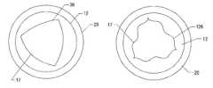
- FIG. 1is a perspective view of a tri-leaflet valve in the open position.
- FIG. 2is a plan view of the valve of FIG. 1 .
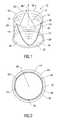
- FIG. 3is a perspective view of a tri-leaflet valve in the closed position.
- FIG. 4is a plan view of the valve of FIG. 3 .
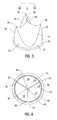
- FIG. 5is a cross-sectional view along lines V on FIG. 4 .
- FIG. 6is a view along lines VI on FIG. 3 .
- FIG. 7is a plan view of a leaflet.
- FIG. 8is an elevation view of a leaflet, viewed along lines VIII on FIG. 7 .
- FIG. 9is a graph of a normalized distance to the triple point vs. position on the attachment curve.
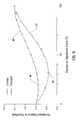
- FIG. 10is a graph of normalized stress vs. edge position.
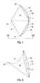
- FIG. 11is a perspective view of a leaflet having regions of maximum loaded stress.
- FIG. 12is a perspective view of a portion of a valve.
- FIG. 13 and 14are perspective views of valve leaflets illustrating a cylindrical analytical shape.
- FIG. 15is a perspective view of a valve leaflet illustrating a conical analytic shape.
- FIG. 16is a perspective view of a valve leaflet illustrating a paraboloid analytic shape.
- FIG. 17is a perspective view of a valve leaflet illustrating an ellipsoid analytic shape.
- FIG. 18is a perspective view of a valve leaflet illustrating a parabolic cylinder analytic shape.
- FIG. 19is a perspective view of a valve leaflet illustrating an elliptical cylinder.
- FIGS. 20, 21 and 22are top plan views of a valve showing a feature of an inner wall, in highly exaggerated scale.
- a tri-leaflet heart valve prosthesis 10comprises an annular valve body 12 and three flexible leaflets 14 made of a biocompatible polymer such as silicone or polyurethane, as shown in FIG. 1, or of tissue. It is important that the leaflet material have an analytic shape in a selected position, as explained hereafter.
- the selected positionis preferably a “no-load” position such that the leaflet is not distorted by pressures on the leaflet.
- the selected position of the leafletmay be closed, partially closed, or open with respect to the valve body. The selected position may be selected for ease of manufacturing.
- An analytic shapeis a shape which can be represented generally by analytic geometry.
- An analytic shapemay include a portion of a cylindrical surface, of an ellipsoid, of a paraboloid, or of another shape that can be defined mathematically.
- Typical production methods for polymer structuressuch as molding or die casting, can produce leaflets having analytic shapes in a selected position.
- the annular valve body and leafletsare typically molded as a single piece.
- Tissuesuch as porcine or bovine pericardium, can also be formed into leaflets having an analytic shape in a selected position, if the tissue is fixed or cured on a mandrel or other structure imparting a shape to the leaflet.
- Gluteraldehydemay be used to fix the tissue, although other methods known in the art may also be used.
- the resulting leafletswill have a shape in a selected position which can be defined as a regular, axially symmetrical shape over at least a greater part of the leaflet.
- Such shapesinclude portions of cylinders, ellipsoids, paraboloids, or other shapes that can be similarly mathematically defined.
- Each leafletis coupled to the valve body along an attachment curve 16 .
- An inner wall 17 of the valve bodyconforms to the attachment curve adjacent the attachment curve.
- the inner wall 17seen in top plan view, will be non-cylindrical at least in part, as explained in connection with FIG. 7, below.
- Each leaflethas a free edge 18 that is not coupled to the valve body.
- a sewing ring 20is coupled to the base of the valve body 12 and provides a place for sutures to be applied when the valve is implanted.
- the valve bodycomprises an annular base 22 and a leaflet support, comprising shaped posts 24 , that supports the leaflets 14 .
- each of the leafletsWhen fluid flow is in the reverse direction, i.e. in the direction of the arrow shown in FIG. 3, the pressure of the blood flow causes the leaflets to deflect toward axis 26 , as shown in FIGS. 3 and 4.
- each of the leafletsIn this “closed” position, where the three leaflets are closed and are subject to a load in the reverse direction, each of the leaflets would occlude more than one-third of the valve body's orifice were it not for the presence of the other leaflets. Consequently, when the three leaflets deflect toward axis 26 , they engage each other and form coaptive areas 28 , as shown in FIG. 5, which help the valve seal against reverse flow. Further, when the leaflets press together, each leaflet forms a “triple point” 30 at the point where the three leaflets come together, as shown in FIG. 6 .
- each leaflethas a small bending radius in the vicinity of the commissure.
- the flexible leafletsare generally manufactured by molding and cutting the leaflet along the free edge (including the commissure) to match design criteria. Both of these factors are stress risers, which makes the commissure 32 a location of high stress risers.
- a point at or near a leaflet's triple point 30experiences the maximum displacement of any point on the leaflet between the valve's open and closed position. If the leaflet is imagined as a collection of non-interconnecting spans connecting the triple point to the attachment curve, the triple-point end of each of those spans experiences the same displacement between the valve's open and closed positions.
- the material properties of the leafletshould be chosen such that the leaflet can be reasonably modeled by an analytic shape, that is by a surface comprising a portion of a cylinder, an ellipsoid, a paraboloid, or other shape that can be similarly mathematically defined as a surface of rotation about an axis or as a surface symmetrical about a plane.
- the selected position for the leafletsis the closed position, the small deflection of the leaflets resulting from the coaptive areas does not contribute significantly to the stress experienced by the leaflet.
- the maximum stress when the leaflet is in its selected position, or “maximum loaded stress”,will occur along the span, measured along the surface of the leaflet, with the shortest original length.
- the configuration of the attachment curvehas not been selected with respect to an analytic shape of the leaflets.
- the valve bodieshave had a circular cross section, that is, a cylindrical inner wall.
- the span with the shortest original lengthconnects the triple point 30 to the commissure 32 , which means the point of maximum loaded stress will occur along this span.
- the commissure 32is a location of high stress risers. The presence of both the point of maximum loaded stress and high stress risers at the commissure 32 increases the high likelihood that the leaflet will fail at the commissure 32 .
- the valve leaflets 18are given an analytic shape, such as a portion of a cylindrical surface 110 (FIG. 13 and FIG. 14 ), an ellipsoid 112 (FIG. 17 ), a paraboloid 114 (FIG. 16 ), or other shape that can be similarly mathematically defined.
- a portion of a conical surface 116 (FIG. 15)may also be used.
- the aforementioned shapesare generally symmetrical around an axis of symmetry 118 . Shapes symmetrical about a plane of symmetry could also be used.
- Such shapesinclude parabolic cylinders 122 (i.e., a projection of a parabola out of an x-y plane along a z axis) or elliptical cylinders 124 (i.e., a projection of an ellipse out of an x-y plane along a z axis) or similar shapes.
- FIGS. 18 and 19illustrate leaflets shapes on a parabolic cylinder and an elliptical cylinder respectively.
- the material of the leafletsis selected such that the leaflets generally maintain this analytic shape in a selected position.
- Such materialmay be a polymer such as polyurethane or silicon rubber, or tissue such as porcine or bovine pericardium which has been cured in a particular shape, for example, on a mandrel.
- the shape of each leafletis preferably a portion of a shape which would be symmetrical around an axis of symmetry 118 or a plane of symmetry 120 for that leaflet. In a tri-leaflet valve these axes or planes would usually be spaced at 120 ⁇ around an axis of flow through the triple point of the valve.
- An attachment curve for the leafletis then selected. Because leaflets have an analytic shape, mathematical modeling can be used to predict the stress at the attachment curve.
- the present inventionreduces the likelihood of leaflet failure by moving the location of maximum loaded stress away from the location of stress risers, i.e. away from the commissures.
- the inventionreduces the likelihood of leaflet failure by moving the location of maximum loaded stress away from the commissure 32 .
- Thisis accomplished by changing the geometry of the attachment curve 16 so that the shortest distance along the surface of the leaflet from the triple point 30 to the attachment curve 16 is not along the leaflet's free edge 18 . This moves the location of the point of maximum loaded stress away from the free edge 18 and away from the commissure 32 .
- the configuration of the valve body, and in particular the shape of the inner wall 17 of the valve body adjacent the attachment curveis selected to conform to the attachment curve.
- Sections of the valve body in planes perpendicular to the axis of flow and intersecting the attachment curvewill usually disclose a non-circular shape for the inner wall of the valve body.
- a projection of the attachment curve onto a plane perpendicular to the axis of flowwill also be non-circular.
- the inner wall 17 of the valve bodymay transition to circular or elliptical away from the attachment curve.
- an outer wall of the valve bodymay have a cylindrical, elliptical, or other configuration without affecting the attachment curve between a leaflet and the valve body.
- the location of the point of maximum loaded stressmay be moved by changing the geometry of the attachment curve.
- the geometry of the attachment curvewhere the geometry of the leaflet 14 is defined or pre-selected, determines the geometry of the inner wall of the valve body 12 . If the leaflet shape is held constant, the attachment curve which produces a cylindrical inner wall 36 of a valve body is different than one which produces a non-cylindrical inner wall of a valve body.
- an attachment curvemay be selected that produces an inner wall of the valve body that is either convex 38 or concave 40 relative to cylindrical, as illustrated in FIGS. 7 and 8.
- Leaflet 14is symmetrical around midline 34 .
- a first attachment curvemay produce a circular inner wall 36 of the valve body.
- a second attachment curvemay produce an inner wall 38 of the valve body that is concave relative to a cylindrical shape. This may produce, for example, an inner wall 36 which may be represented by a polygon with curved faces, as shown in FIG. 20, in highly exaggerated scale.
- a third attachment curvemay produce an inner wall 40 of the valve body which has a shape that is convex relative to a cylindrical shape, for example. This shape of the inner wall may also be characterized as a polygon, but with faces that bulge out beyond a radial distance containing the vertices of the polygon, as shown in FIG. 21, also in highly exaggerated scale.
- heart valves with flexible leafletshave been designed by selecting a design for an attachment curve and then forming the attachment curve, often embodied in a stent, around the valve body, which was usually provided with a cylindrical inner wall, or other cylindrical structure for supporting the stent.
- the leafletswere then provided to occlude the orifice.
- the shape and dimensions of the leafletswere not the primary design parameters.
- an analytic shape of the leafletis selected first. Then the dimensions of the leaflet arc determined by selecting an attachment curve. Because the analytic shape of the leaflet has been pre-selected, the stresses along the attachment curve can be calculated and an attachment curve can be selected which distributes and reduces stresses.
- the selection of the analytic shape of the leaflet and the attachment curvedetermines the shape of the inner wall of the valve body, which is non-cylindrical in a preferred embodiment.
- the analytic shape of the leafletis selected first, distances from the triple point to the attachment curve along the surface of the leaflet can be calculated.
- the distance from the triple point to the attachment curve for inner wall 38is different than the distance from the triple point to attachment curve for inner wall 40 , as illustrated in FIG. 9, for a cylindrical analytic shape for the leaflet.
- the vertical axisis the normalized distance from the triple point to the attachment curve along a leaflet having a cylindrical analytical shape, with the normalization factor being the distance from the triple point to the commissure.
- the horizontal axisrepresents the edge position, measured as a percentage of the arc from the commissure to the intersection of the leaflet midline 34 with the attachment curve.
- the commissureis at zero percent and the intersection of the midline 34 with the attachment curve is at one-hundred percent.
- Half way along the attachment curve between those two pointsis fifty percent.
- Curve 42illustrates the normalized distance along the surface of the leaflet between the triple point and each point on the concave attachment curve 38 .
- Curve 44illustrates the normalized distance along the surface of the leaflet between the triple point and each point on the convex attachment curve 40 .
- a distance along the leafletcan be determined because the leaflets have an analytic shape. Since the distance along the leaflet from the triple point to a point on the attachment curve is inversely proportional to the stress at that point on the attachment curve, in the absence of stress risers a curve may be selected which distributes the stress away from stress risers, i.e., away from the commissures, and which smooths the stress distribution.
- the minimum distance point 46occurs at approximately twenty percent and has a normalized value just less than 1.0.
- the minimum distance point 48occurs at approximately thirty percent and has a normalized value of less than 0.9.
- the minimum distance along the surface of the leaflet from the triple point to the attachment curveis different for attachment curve 38 than it is for attachment curve 40 (FIG. 7 ).
- the minimum distance pointis in a different location along the attachment curve for attachment curve 38 than it is for attachment curve 40 .
- FIG. 10The chart in FIG. 10 has a vertical axis representing normalized stress with the normalization factor being the maximum stress shown on the Figure.
- the horizontal axisis the same as the horizontal axis in FIG. 9 .
- Curve 50illustrates the loaded stress along convex attachment curve 40 .
- Curves 50 and 52were produced by performing a finite element analysis of the respective geometries of the convex and concave leaflet designs.
- the point of maximum loaded stress 54 on convex attachment curve 52occurs between the twenty- and thirty-degree points and experiences a normalized stress of approximately 0.90.
- the point of maximum loaded stress 56 on concave attachment curve 50occurs between the thirty- and forty-degree points and experiences a normalized stress of 1.0. This demonstrates that the point of maximum loaded stress can be moved and the amount of stress that point experiences can be changed by changing the geometry of the attachment curve which results in modification of the valve body geometry, specifically through modification of the inner wall of the valve body.
- the magnitude of the maximum loaded stresscan be further modified by changing the attachment curve to increase the distance from the leaflet's point of maximum displacement (or triple point) to “regions” 58 , 60 in the vicinity of points of maximum loaded stress 62 , 64 on the leaflet's attachment curve, as shown in FIG. 11 .
- Such a shape 126is illustrated in FIG. 22, in highly exaggerated scale. This change in shape may cause the point of maximum loaded stress to change location, which may make it necessary to change the geometry of the attachment curve to reposition the point of maximum loaded stress once again.
- the design of the attachment curve and the distance from the point of maximum displacement of the triple pointcan be iteratively revised until design criteria are met. Once the shape of the attachment curve has been determined, the adjacent inner wall of the valve body is configured to intersect the attachment curve.
- the maximum loaded stresscan be spread over the regions 58 and 60 of the leaflet by designing the attachment curve so that the regions 58 and 60 are equally distant from the point of maximum displacement of the triple point. The result would be a region of points experiencing maximum loaded stress rather than a single point, further reducing the likelihood of leaflet failure at the single point.
- the leaflet geometryis circularly cylindrical and the attachment curve produces a valve body geometry which is convex of cylindrical such as curve 40 illustrated in FIGS. 7 and 8.
- valve body 98has a different shape at the elevation of the attachment curve than its shape at its base.
- leaflet 100is coupled to valve body 98 along attachment curve 102 .
- the inner wall 103 of the valve bodyis non-circular near the attachment curve.
- the inner wall at the base of the valve body 100has a circular shape 104 .
- the attachment curve 102is shaped so that its projection onto the plane containing circle 104 is not a circle.
- the attachment curve 102can be shaped to locate the point of maximum loaded stress to meet design requirements and the inner wall of the valve body can be shaped to intersect the selected attachment curve while not affecting other design parameters, such as the shape of the valve body 12 where the sewing ring is coupled to it.
Landscapes
- Health & Medical Sciences (AREA)
- Engineering & Computer Science (AREA)
- Biomedical Technology (AREA)
- Cardiology (AREA)
- Oral & Maxillofacial Surgery (AREA)
- Transplantation (AREA)
- Heart & Thoracic Surgery (AREA)
- Vascular Medicine (AREA)
- Life Sciences & Earth Sciences (AREA)
- Animal Behavior & Ethology (AREA)
- General Health & Medical Sciences (AREA)
- Public Health (AREA)
- Veterinary Medicine (AREA)
- Prostheses (AREA)
- Valve-Gear Or Valve Arrangements (AREA)
Abstract
Description
Claims (19)
Priority Applications (1)
| Application Number | Priority Date | Filing Date | Title |
|---|---|---|---|
| US09/523,804US6613086B1 (en) | 1998-06-24 | 2000-03-13 | Altering heart valve leaflet attachment geometry to influence the location and magnitude of maximum loaded stress on the leaflet |
Applications Claiming Priority (2)
| Application Number | Priority Date | Filing Date | Title |
|---|---|---|---|
| US10348298A | 1998-06-24 | 1998-06-24 | |
| US09/523,804US6613086B1 (en) | 1998-06-24 | 2000-03-13 | Altering heart valve leaflet attachment geometry to influence the location and magnitude of maximum loaded stress on the leaflet |
Related Parent Applications (1)
| Application Number | Title | Priority Date | Filing Date |
|---|---|---|---|
| US10348298AContinuation-In-Part | 1998-06-24 | 1998-06-24 |
Publications (1)
| Publication Number | Publication Date |
|---|---|
| US6613086B1true US6613086B1 (en) | 2003-09-02 |
Family
ID=22295429
Family Applications (1)
| Application Number | Title | Priority Date | Filing Date |
|---|---|---|---|
| US09/523,804Expired - LifetimeUS6613086B1 (en) | 1998-06-24 | 2000-03-13 | Altering heart valve leaflet attachment geometry to influence the location and magnitude of maximum loaded stress on the leaflet |
Country Status (5)
| Country | Link |
|---|---|
| US (1) | US6613086B1 (en) |
| EP (1) | EP1089676A2 (en) |
| JP (1) | JP2002518131A (en) |
| CA (1) | CA2305730A1 (en) |
| WO (1) | WO1999066863A2 (en) |
Cited By (81)
| Publication number | Priority date | Publication date | Assignee | Title |
|---|---|---|---|---|
| US20040024452A1 (en)* | 2002-08-02 | 2004-02-05 | Kruse Steven D. | Valved prostheses with preformed tissue leaflets |
| WO2004082536A1 (en)* | 2003-03-20 | 2004-09-30 | Aortech International Plc | Valve |
| WO2005072654A1 (en) | 2004-01-23 | 2005-08-11 | Edwards Lifesciences Corporation | Anatomically approximate prosthetic mitral heart valve |
| US20060229716A1 (en)* | 2005-04-11 | 2006-10-12 | Zan Mitrev | Replacement aortic valve leaflets and related technology |
| US20070021826A1 (en)* | 2003-04-24 | 2007-01-25 | Cook Incorporated | Intralumenally implantable frames |
| US20070038291A1 (en)* | 2003-04-24 | 2007-02-15 | Cook Incorporated | Intralumenally-implantable frames |
| US20070260327A1 (en)* | 2003-04-24 | 2007-11-08 | Case Brian C | Artificial Valve Prosthesis with Improved Flow Dynamics |
| US20080147179A1 (en)* | 2006-12-19 | 2008-06-19 | St. Jude Medical, Inc. | Prosthetic heart valve including stent structure and tissue leaflets, and related methods |
| US7704222B2 (en) | 1998-09-10 | 2010-04-27 | Jenavalve Technology, Inc. | Methods and conduits for flowing blood from a heart chamber to a blood vessel |
| US7717952B2 (en) | 2003-04-24 | 2010-05-18 | Cook Incorporated | Artificial prostheses with preferred geometries |
| US7896913B2 (en) | 2000-02-28 | 2011-03-01 | Jenavalve Technology, Inc. | Anchoring system for implantable heart valve prostheses |
| US7896915B2 (en) | 2007-04-13 | 2011-03-01 | Jenavalve Technology, Inc. | Medical device for treating a heart valve insufficiency |
| US20110208299A1 (en)* | 2008-08-19 | 2011-08-25 | Roelof Marissen | Implantable valve prosthesis and method for manufacturing such a valve |
| US8038708B2 (en) | 2001-02-05 | 2011-10-18 | Cook Medical Technologies Llc | Implantable device with remodelable material and covering material |
| US8062355B2 (en) | 2005-11-04 | 2011-11-22 | Jenavalve Technology, Inc. | Self-expandable medical instrument for treating defects in a patient's heart |
| US8092521B2 (en) | 2005-10-28 | 2012-01-10 | Jenavalve Technology, Inc. | Device for the implantation and fixation of prosthetic valves |
| US8206437B2 (en) | 2001-08-03 | 2012-06-26 | Philipp Bonhoeffer | Implant implantation unit and procedure for implanting the unit |
| US8317858B2 (en) | 2008-02-26 | 2012-11-27 | Jenavalve Technology, Inc. | Stent for the positioning and anchoring of a valvular prosthesis in an implantation site in the heart of a patient |
| US8398704B2 (en) | 2008-02-26 | 2013-03-19 | Jenavalve Technology, Inc. | Stent for the positioning and anchoring of a valvular prosthesis in an implantation site in the heart of a patient |
| US8465540B2 (en) | 2008-02-26 | 2013-06-18 | Jenavalve Technology, Inc. | Stent for the positioning and anchoring of a valvular prosthesis |
| US8468667B2 (en) | 2009-05-15 | 2013-06-25 | Jenavalve Technology, Inc. | Device for compressing a stent |
| US8679174B2 (en) | 2005-01-20 | 2014-03-25 | JenaValve Technology, GmbH | Catheter for the transvascular implantation of prosthetic heart valves |
| US8764818B2 (en) | 2011-07-20 | 2014-07-01 | Boston Scientific Scimed, Inc. | Heart valve replacement |
| USRE45130E1 (en) | 2000-02-28 | 2014-09-09 | Jenavalve Technology Gmbh | Device for fastening and anchoring cardiac valve prostheses |
| US9011523B2 (en) | 2011-06-20 | 2015-04-21 | Jacques Seguin | Prosthetic leaflet assembly for repairing a defective cardiac valve and methods of using the same |
| US9044318B2 (en) | 2008-02-26 | 2015-06-02 | Jenavalve Technology Gmbh | Stent for the positioning and anchoring of a valvular prosthesis |
| US9101469B2 (en) | 2012-12-19 | 2015-08-11 | W. L. Gore & Associates, Inc. | Prosthetic heart valve with leaflet shelving |
| US9138315B2 (en) | 2007-04-13 | 2015-09-22 | Jenavalve Technology Gmbh | Medical device for treating a heart valve insufficiency or stenosis |
| US9144492B2 (en) | 2012-12-19 | 2015-09-29 | W. L. Gore & Associates, Inc. | Truncated leaflet for prosthetic heart valves, preformed valve |
| US9161835B2 (en) | 2010-09-30 | 2015-10-20 | BioStable Science & Engineering, Inc. | Non-axisymmetric aortic valve devices |
| US9168130B2 (en) | 2008-02-26 | 2015-10-27 | Jenavalve Technology Gmbh | Stent for the positioning and anchoring of a valvular prosthesis in an implantation site in the heart of a patient |
| US9283072B2 (en) | 2012-07-25 | 2016-03-15 | W. L. Gore & Associates, Inc. | Everting transcatheter valve and methods |
| US9295551B2 (en) | 2007-04-13 | 2016-03-29 | Jenavalve Technology Gmbh | Methods of implanting an endoprosthesis |
| US9301837B2 (en) | 2014-05-09 | 2016-04-05 | Foldax, Inc. | Replacement heart valves and their methods of use and manufacture |
| US9398952B2 (en) | 2012-12-19 | 2016-07-26 | W. L. Gore & Associates, Inc. | Planar zone in prosthetic heart valve leaflet |
| US9510947B2 (en) | 2011-10-21 | 2016-12-06 | Jenavalve Technology, Inc. | Catheter system for introducing an expandable heart valve stent into the body of a patient |
| US9597182B2 (en) | 2010-05-20 | 2017-03-21 | Jenavalve Technology Inc. | Catheter system for introducing an expandable stent into the body of a patient |
| US9629720B2 (en) | 2015-05-04 | 2017-04-25 | Jacques Seguin | Apparatus and methods for treating cardiac valve regurgitation |
| US9737398B2 (en) | 2012-12-19 | 2017-08-22 | W. L. Gore & Associates, Inc. | Prosthetic valves, frames and leaflets and methods thereof |
| US9744031B2 (en) | 2010-05-25 | 2017-08-29 | Jenavalve Technology, Inc. | Prosthetic heart valve and endoprosthesis comprising a prosthetic heart valve and a stent |
| US9839515B2 (en) | 2005-12-22 | 2017-12-12 | Symetis, SA | Stent-valves for valve replacement and associated methods and systems for surgery |
| CN107485465A (en)* | 2011-12-09 | 2017-12-19 | 爱德华兹生命科学公司 | The heart valve prosthesis of commissure support with improvement |
| US9844434B2 (en) | 2006-10-06 | 2017-12-19 | BioStable Science & Engineering, Inc. | Intra-annular mounting frame for aortic valve repair |
| US9867694B2 (en) | 2013-08-30 | 2018-01-16 | Jenavalve Technology Inc. | Radially collapsible frame for a prosthetic valve and method for manufacturing such a frame |
| US9867699B2 (en) | 2008-02-26 | 2018-01-16 | Jenavalve Technology, Inc. | Endoprosthesis for implantation in the heart of a patient |
| US9878127B2 (en) | 2012-05-16 | 2018-01-30 | Jenavalve Technology, Inc. | Catheter delivery system for heart valve prosthesis |
| US9968443B2 (en) | 2012-12-19 | 2018-05-15 | W. L. Gore & Associates, Inc. | Vertical coaptation zone in a planar portion of prosthetic heart valve leaflet |
| US10039638B2 (en) | 2012-12-19 | 2018-08-07 | W. L. Gore & Associates, Inc. | Geometric prosthetic heart valves |
| US10231833B2 (en) | 2016-10-28 | 2019-03-19 | Foldax, Inc. | Prosthetic heart valves with elastic support structures and related methods |
| US10321986B2 (en) | 2012-12-19 | 2019-06-18 | W. L. Gore & Associates, Inc. | Multi-frame prosthetic heart valve |
| US10376360B2 (en) | 2012-07-27 | 2019-08-13 | W. L. Gore & Associates, Inc. | Multi-frame prosthetic valve apparatus and methods |
| US10639154B2 (en) | 2014-10-16 | 2020-05-05 | Jacques Seguin | Intervalvular implant for a mitral valve |
| US10709555B2 (en) | 2015-05-01 | 2020-07-14 | Jenavalve Technology, Inc. | Device and method with reduced pacemaker rate in heart valve replacement |
| US10940167B2 (en) | 2012-02-10 | 2021-03-09 | Cvdevices, Llc | Methods and uses of biological tissues for various stent and other medical applications |
| US10959842B2 (en) | 2017-09-12 | 2021-03-30 | W. L. Gore & Associates, Inc. | Leaflet frame attachment for prosthetic valves |
| US10966820B2 (en) | 2012-12-19 | 2021-04-06 | W. L. Gore & Associates, Inc. | Geometric control of bending character in prosthetic heart valve leaflets |
| US10987218B2 (en) | 2017-10-31 | 2021-04-27 | W. L. Gore & Associates, Inc. | Transcatheter deployment systems and associated methods |
| US11000369B2 (en) | 2017-12-11 | 2021-05-11 | California Institute Of Technolgy | Systems, devices, and methods relating to the manufacture of intravascularly implantable prosthetic valves |
| US11020221B2 (en) | 2017-09-27 | 2021-06-01 | W. L. Gore & Associates, Inc. | Prosthetic valve with expandable frame and associated systems and methods |
| US11039919B2 (en) | 2017-10-31 | 2021-06-22 | W. L. Gore & Associates, Inc. | Valved conduit |
| US11065138B2 (en) | 2016-05-13 | 2021-07-20 | Jenavalve Technology, Inc. | Heart valve prosthesis delivery system and method for delivery of heart valve prosthesis with introducer sheath and loading system |
| US11065112B2 (en) | 2014-08-18 | 2021-07-20 | W. L. Gore & Associates, Inc. | Frame with integral sewing cuff for prosthetic valves |
| USD926322S1 (en) | 2018-11-07 | 2021-07-27 | W. L. Gore & Associates, Inc. | Heart valve cover |
| US11090153B2 (en) | 2017-10-13 | 2021-08-17 | W. L. Gore & Associates, Inc. | Telescoping prosthetic valve and delivery system |
| US11109963B2 (en) | 2017-09-27 | 2021-09-07 | W. L. Gore & Associates, Inc. | Prosthetic valves with mechanically coupled leaflets |
| US11123183B2 (en) | 2017-10-31 | 2021-09-21 | W. L. Gore & Associates, Inc. | Prosthetic heart valve |
| US11154397B2 (en) | 2017-10-31 | 2021-10-26 | W. L. Gore & Associates, Inc. | Jacket for surgical heart valve |
| US11197754B2 (en) | 2017-01-27 | 2021-12-14 | Jenavalve Technology, Inc. | Heart valve mimicry |
| US11278406B2 (en) | 2010-05-20 | 2022-03-22 | Jenavalve Technology, Inc. | Catheter system for introducing an expandable heart valve stent into the body of a patient, insertion system with a catheter system and medical device for treatment of a heart valve defect |
| US11351058B2 (en) | 2017-03-17 | 2022-06-07 | W. L. Gore & Associates, Inc. | Glaucoma treatment systems and methods |
| US11406495B2 (en) | 2013-02-11 | 2022-08-09 | Cook Medical Technologies Llc | Expandable support frame and medical device |
| US11439502B2 (en) | 2017-10-31 | 2022-09-13 | W. L. Gore & Associates, Inc. | Medical valve and leaflet promoting tissue ingrowth |
| US11471276B2 (en) | 2014-09-15 | 2022-10-18 | W. L. Gore & Associates, Inc. | Prosthetic heart valve with retention elements |
| US11497601B2 (en) | 2019-03-01 | 2022-11-15 | W. L. Gore & Associates, Inc. | Telescoping prosthetic valve with retention element |
| USD977642S1 (en) | 2018-10-29 | 2023-02-07 | W. L. Gore & Associates, Inc. | Pulmonary valve conduit |
| US11617644B2 (en) | 2014-10-13 | 2023-04-04 | W. L. Gore & Associates, Inc. | Prosthetic valved conduit |
| US11678983B2 (en) | 2018-12-12 | 2023-06-20 | W. L. Gore & Associates, Inc. | Implantable component with socket |
| US12121461B2 (en) | 2015-03-20 | 2024-10-22 | Jenavalve Technology, Inc. | Heart valve prosthesis delivery system and method for delivery of heart valve prosthesis with introducer sheath |
| US12171658B2 (en) | 2022-11-09 | 2024-12-24 | Jenavalve Technology, Inc. | Catheter system for sequential deployment of an expandable implant |
| US12239573B2 (en) | 2018-08-29 | 2025-03-04 | W. L. Gore & Associates, Inc. | Drug therapy delivery systems and methods |
| US12285331B2 (en) | 2019-03-18 | 2025-04-29 | Foldax, Inc. | Systems, devices, and methods relating to the manufacture of implantable prosthetic valves |
Families Citing this family (5)
| Publication number | Priority date | Publication date | Assignee | Title |
|---|---|---|---|---|
| US6454799B1 (en) | 2000-04-06 | 2002-09-24 | Edwards Lifesciences Corporation | Minimally-invasive heart valves and methods of use |
| US6893460B2 (en) | 2001-10-11 | 2005-05-17 | Percutaneous Valve Technologies Inc. | Implantable prosthetic valve |
| GB2440809B (en)* | 2006-07-28 | 2011-08-10 | Geoffrey Douglas Tansley | Improved heart valve prosthesis |
| DK4233795T3 (en) | 2010-10-05 | 2024-08-26 | Edwards Lifesciences Corp | Prosthetic heart valve |
| GB202400525D0 (en)* | 2024-01-15 | 2024-02-28 | Cambridge Entpr Ltd | Apparatus |
Citations (19)
| Publication number | Priority date | Publication date | Assignee | Title |
|---|---|---|---|---|
| US3714671A (en) | 1970-11-30 | 1973-02-06 | Cutter Lab | Tissue-type heart valve with a graft support ring or stent |
| US4470157A (en) | 1981-04-27 | 1984-09-11 | Love Jack W | Tricuspid prosthetic tissue heart valve |
| US4626255A (en) | 1983-09-23 | 1986-12-02 | Christian Weinhold | Heart valve bioprothesis |
| US4759758A (en) | 1984-12-07 | 1988-07-26 | Shlomo Gabbay | Prosthetic heart valve |
| US4778461A (en) | 1985-11-23 | 1988-10-18 | Beiersdorf Ag | Heart valve prosthesis and process for its production |
| US5500016A (en) | 1992-03-25 | 1996-03-19 | University Of Leeds | Artificial heart valve |
| US5562729A (en) | 1994-11-01 | 1996-10-08 | Biocontrol Technology, Inc. | Heart valve |
| US5607442A (en)* | 1995-11-13 | 1997-03-04 | Isostent, Inc. | Stent with improved radiopacity and appearance characteristics |
| WO1997041808A1 (en) | 1996-05-05 | 1997-11-13 | Medicard Limited | Method for producing heart valves |
| WO1997049356A1 (en) | 1996-06-24 | 1997-12-31 | Adiam Medizintechnik Gmbh & Co. Kg | Mitral valve prosthesis |
| US5716417A (en)* | 1995-06-07 | 1998-02-10 | St. Jude Medical, Inc. | Integral supporting structure for bioprosthetic heart valve |
| US5776161A (en)* | 1995-10-16 | 1998-07-07 | Instent, Inc. | Medical stents, apparatus and method for making same |
| US5861028A (en) | 1996-09-09 | 1999-01-19 | Shelhigh Inc | Natural tissue heart valve and stent prosthesis and method for making the same |
| US5895420A (en) | 1995-06-07 | 1999-04-20 | St. Jude Medical, Inc. | Bioresorbable heart valve support |
| US5928281A (en) | 1997-03-27 | 1999-07-27 | Baxter International Inc. | Tissue heart valves |
| US5935163A (en) | 1998-03-31 | 1999-08-10 | Shelhigh, Inc. | Natural tissue heart valve prosthesis |
| US6051022A (en)* | 1998-12-30 | 2000-04-18 | St. Jude Medical, Inc. | Bileaflet valve having non-parallel pivot axes |
| US6179869B1 (en)* | 1996-07-11 | 2001-01-30 | Tricumed Medizintechnik Gmbh | Artificial heart valve |
| US6328763B1 (en)* | 1995-10-06 | 2001-12-11 | Cardiomend, Llc | Optimized geometry of a tissue pattern for semilunar heart valve reconstruction |
- 1999
- 1999-06-23EPEP99930591Apatent/EP1089676A2/ennot_activeWithdrawn
- 1999-06-23WOPCT/US1999/014189patent/WO1999066863A2/ennot_activeApplication Discontinuation
- 1999-06-23CACA002305730Apatent/CA2305730A1/ennot_activeAbandoned
- 1999-06-23JPJP2000555551Apatent/JP2002518131A/ennot_activeWithdrawn
- 2000
- 2000-03-13USUS09/523,804patent/US6613086B1/ennot_activeExpired - Lifetime
Patent Citations (19)
| Publication number | Priority date | Publication date | Assignee | Title |
|---|---|---|---|---|
| US3714671A (en) | 1970-11-30 | 1973-02-06 | Cutter Lab | Tissue-type heart valve with a graft support ring or stent |
| US4470157A (en) | 1981-04-27 | 1984-09-11 | Love Jack W | Tricuspid prosthetic tissue heart valve |
| US4626255A (en) | 1983-09-23 | 1986-12-02 | Christian Weinhold | Heart valve bioprothesis |
| US4759758A (en) | 1984-12-07 | 1988-07-26 | Shlomo Gabbay | Prosthetic heart valve |
| US4778461A (en) | 1985-11-23 | 1988-10-18 | Beiersdorf Ag | Heart valve prosthesis and process for its production |
| US5500016A (en) | 1992-03-25 | 1996-03-19 | University Of Leeds | Artificial heart valve |
| US5562729A (en) | 1994-11-01 | 1996-10-08 | Biocontrol Technology, Inc. | Heart valve |
| US5895420A (en) | 1995-06-07 | 1999-04-20 | St. Jude Medical, Inc. | Bioresorbable heart valve support |
| US5716417A (en)* | 1995-06-07 | 1998-02-10 | St. Jude Medical, Inc. | Integral supporting structure for bioprosthetic heart valve |
| US6328763B1 (en)* | 1995-10-06 | 2001-12-11 | Cardiomend, Llc | Optimized geometry of a tissue pattern for semilunar heart valve reconstruction |
| US5776161A (en)* | 1995-10-16 | 1998-07-07 | Instent, Inc. | Medical stents, apparatus and method for making same |
| US5607442A (en)* | 1995-11-13 | 1997-03-04 | Isostent, Inc. | Stent with improved radiopacity and appearance characteristics |
| WO1997041808A1 (en) | 1996-05-05 | 1997-11-13 | Medicard Limited | Method for producing heart valves |
| WO1997049356A1 (en) | 1996-06-24 | 1997-12-31 | Adiam Medizintechnik Gmbh & Co. Kg | Mitral valve prosthesis |
| US6179869B1 (en)* | 1996-07-11 | 2001-01-30 | Tricumed Medizintechnik Gmbh | Artificial heart valve |
| US5861028A (en) | 1996-09-09 | 1999-01-19 | Shelhigh Inc | Natural tissue heart valve and stent prosthesis and method for making the same |
| US5928281A (en) | 1997-03-27 | 1999-07-27 | Baxter International Inc. | Tissue heart valves |
| US5935163A (en) | 1998-03-31 | 1999-08-10 | Shelhigh, Inc. | Natural tissue heart valve prosthesis |
| US6051022A (en)* | 1998-12-30 | 2000-04-18 | St. Jude Medical, Inc. | Bileaflet valve having non-parallel pivot axes |
Non-Patent Citations (5)
| Title |
|---|
| Chandran, K.B., et al., "Stress Distribution on the Cusps of a Polyurethane Trileaflet Heart Valve Prosthesis in the Closed Position",J. Biomechanics, vol. 24, No. 6, pp. 385-395, 1991. |
| Christie, G. W., et al., "On Stress Reduction in Bioprosthetic Heart Valve Leaflets by the US of a Flexible Stent",Journal of Cardiac Surgery, vol. 6, No. 4, pp. 476-481, 1991. |
| Christie, G. W., et al., "Stress-Related Failure Modes of Bovine Pericardial Heart Valves", Bioprostheses: Design & Material, pp. 765-779. |
| Christie, G.W., "The Bovine Pericardial Bioprosthetic Heart Valve: Methods for Tensile Stress Reduction in the Leaflets During the Loaded Phase",Advances in Bioengineering, BED-vol. 20, pp. 647-650, 1991. |
| Clift, S. E., et al., "Finite Element Stress Analysis of a New Design of Synthetic Leaflet Heart Valve", Journal of Engineering in Medicine, vol. 210, pp. 267-272, 1996. |
Cited By (201)
| Publication number | Priority date | Publication date | Assignee | Title |
|---|---|---|---|---|
| US7736327B2 (en) | 1998-09-10 | 2010-06-15 | Jenavalve Technology, Inc. | Methods and conduits for flowing blood from a heart chamber to a blood vessel |
| US8216174B2 (en) | 1998-09-10 | 2012-07-10 | Jenavalve Technology, Inc. | Methods and conduits for flowing blood from a heart chamber to a blood vessel |
| US7704222B2 (en) | 1998-09-10 | 2010-04-27 | Jenavalve Technology, Inc. | Methods and conduits for flowing blood from a heart chamber to a blood vessel |
| US8597226B2 (en) | 1998-09-10 | 2013-12-03 | Jenavalve Technology, Inc. | Methods and conduits for flowing blood from a heart chamber to a blood vessel |
| USRE45130E1 (en) | 2000-02-28 | 2014-09-09 | Jenavalve Technology Gmbh | Device for fastening and anchoring cardiac valve prostheses |
| US7896913B2 (en) | 2000-02-28 | 2011-03-01 | Jenavalve Technology, Inc. | Anchoring system for implantable heart valve prostheses |
| US8038708B2 (en) | 2001-02-05 | 2011-10-18 | Cook Medical Technologies Llc | Implantable device with remodelable material and covering material |
| US9949824B2 (en) | 2001-08-03 | 2018-04-24 | Jenavalve Technology, Inc. | Devices useful for implantation at a heart valve |
| US8216301B2 (en) | 2001-08-03 | 2012-07-10 | Philipp Bonhoeffer | Implant implantation unit |
| US9889002B2 (en) | 2001-08-03 | 2018-02-13 | Jenavalve Technology, Inc. | Devices useful for implantation at a heart valve |
| US8206437B2 (en) | 2001-08-03 | 2012-06-26 | Philipp Bonhoeffer | Implant implantation unit and procedure for implanting the unit |
| US8585756B2 (en) | 2001-08-03 | 2013-11-19 | Jenavalve Technology, Inc. | Methods of treating valves |
| US8579965B2 (en) | 2001-08-03 | 2013-11-12 | Jenavalve Technology, Inc. | Methods of implanting an implantation device |
| US11007052B2 (en) | 2001-08-03 | 2021-05-18 | Jenavalve Technology, Inc. | Devices useful for implantation at a heart valve |
| US8303653B2 (en) | 2001-08-03 | 2012-11-06 | Philipp Bonhoeffer | Implant implantation unit and procedure for implanting the unit |
| EP1526821A1 (en)* | 2002-08-02 | 2005-05-04 | St. Jude Medical, Inc. | Valved prostheses with preformed tissue leaflets |
| US20040024452A1 (en)* | 2002-08-02 | 2004-02-05 | Kruse Steven D. | Valved prostheses with preformed tissue leaflets |
| US20100047436A1 (en)* | 2003-03-20 | 2010-02-25 | Aortech International Plc | Method of Making a Cardiac Valve |
| US7682389B2 (en) | 2003-03-20 | 2010-03-23 | Aortech International Plc | Cardiac valve featuring a parabolic function |
| GB2407146B (en)* | 2003-03-20 | 2006-04-26 | Aortech Internat Plc | Valve leaflet for use in cardiac valve prosthesis |
| US20060241744A1 (en)* | 2003-03-20 | 2006-10-26 | Aortech International Plc | Valve |
| US7988900B2 (en) | 2003-03-20 | 2011-08-02 | Aortech International Plc | Method of making a cardiac valve |
| GB2407146A (en)* | 2003-03-20 | 2005-04-20 | Aortech Internat Plc | Valve |
| WO2004082536A1 (en)* | 2003-03-20 | 2004-09-30 | Aortech International Plc | Valve |
| US7625399B2 (en) | 2003-04-24 | 2009-12-01 | Cook Incorporated | Intralumenally-implantable frames |
| US7658759B2 (en) | 2003-04-24 | 2010-02-09 | Cook Incorporated | Intralumenally implantable frames |
| US9421096B2 (en) | 2003-04-24 | 2016-08-23 | Cook Medical Technologies Llc | Artificial valve prosthesis with improved flow dynamics |
| US20070260327A1 (en)* | 2003-04-24 | 2007-11-08 | Case Brian C | Artificial Valve Prosthesis with Improved Flow Dynamics |
| US20070038291A1 (en)* | 2003-04-24 | 2007-02-15 | Cook Incorporated | Intralumenally-implantable frames |
| US8221492B2 (en) | 2003-04-24 | 2012-07-17 | Cook Medical Technologies | Artificial valve prosthesis with improved flow dynamics |
| US7717952B2 (en) | 2003-04-24 | 2010-05-18 | Cook Incorporated | Artificial prostheses with preferred geometries |
| US20070021826A1 (en)* | 2003-04-24 | 2007-01-25 | Cook Incorporated | Intralumenally implantable frames |
| US7871435B2 (en) | 2004-01-23 | 2011-01-18 | Edwards Lifesciences Corporation | Anatomically approximate prosthetic mitral heart valve |
| US8721716B2 (en) | 2004-01-23 | 2014-05-13 | Edwards Lifesciences Corporation | Prosthetic heart valve with dissimilar leaflets |
| EP3009105A1 (en) | 2004-01-23 | 2016-04-20 | Edwards Lifesciences Corporation | Anatomically approximate prosthetic mitral heart valve |
| US20110015731A1 (en)* | 2004-01-23 | 2011-01-20 | Edwards Lifesciences Corporation | Anatomically Approximate Prosthetic Mitral Valve |
| US8034104B2 (en) | 2004-01-23 | 2011-10-11 | Edwards Lifesciences Corporation | Anatomically approximate prosthetic mitral valve |
| US20060293745A1 (en)* | 2004-01-23 | 2006-12-28 | Carpentier Alain F | Anatomically approximate prosthetic mitral heart valve |
| WO2005072654A1 (en) | 2004-01-23 | 2005-08-11 | Edwards Lifesciences Corporation | Anatomically approximate prosthetic mitral heart valve |
| US9788945B2 (en) | 2005-01-20 | 2017-10-17 | Jenavalve Technology, Inc. | Systems for implanting an endoprosthesis |
| US8679174B2 (en) | 2005-01-20 | 2014-03-25 | JenaValve Technology, GmbH | Catheter for the transvascular implantation of prosthetic heart valves |
| US9775705B2 (en) | 2005-01-20 | 2017-10-03 | Jenavalve Technology, Inc. | Methods of implanting an endoprosthesis |
| US11517431B2 (en) | 2005-01-20 | 2022-12-06 | Jenavalve Technology, Inc. | Catheter system for implantation of prosthetic heart valves |
| US10492906B2 (en) | 2005-01-20 | 2019-12-03 | Jenavalve Technology, Inc. | Catheter system for implantation of prosthetic heart valves |
| US20060229716A1 (en)* | 2005-04-11 | 2006-10-12 | Zan Mitrev | Replacement aortic valve leaflets and related technology |
| US7462156B2 (en) | 2005-04-11 | 2008-12-09 | Zan Mitrev | Replacement aortic valve leaflets and related technology |
| US10363134B2 (en) | 2005-10-28 | 2019-07-30 | Jenavalve Technology, Inc. | Device for the implantation and fixation of prosthetic valves |
| USRE45962E1 (en) | 2005-10-28 | 2016-04-05 | Jenavalve Technology Gmbh | Device for the implantation and fixation of prosthetic valves |
| USRE45790E1 (en) | 2005-10-28 | 2015-11-03 | Jenavalve Technology Gmbh | Device for the implantation and fixation of prosthetic valves |
| US9402717B2 (en) | 2005-10-28 | 2016-08-02 | Jenavalve Technology, Inc. | Device for the implantation and fixation of prosthetic valves |
| US9855142B2 (en) | 2005-10-28 | 2018-01-02 | JenaValve Technologies, Inc. | Device for the implantation and fixation of prosthetic valves |
| US8834561B2 (en) | 2005-10-28 | 2014-09-16 | Jenavalve Technology Gmbh | Device for the implantation and fixation of prosthetic valves |
| US8092521B2 (en) | 2005-10-28 | 2012-01-10 | Jenavalve Technology, Inc. | Device for the implantation and fixation of prosthetic valves |
| US11116628B2 (en) | 2005-10-28 | 2021-09-14 | Jenavalve Technology, Inc. | Device for the implantation and fixation of prosthetic valves |
| US9044320B2 (en) | 2005-10-28 | 2015-06-02 | Jenavalve Technology Gmbh | Device for the implantation and fixation of prosthetic valves |
| US8551160B2 (en) | 2005-10-28 | 2013-10-08 | Jenavalve Technology, Inc. | Device for the implantation and fixation of prosthetic valves |
| US8062355B2 (en) | 2005-11-04 | 2011-11-22 | Jenavalve Technology, Inc. | Self-expandable medical instrument for treating defects in a patient's heart |
| US10314701B2 (en) | 2005-12-22 | 2019-06-11 | Symetis Sa | Stent-valves for valve replacement and associated methods and systems for surgery |
| US10265167B2 (en) | 2005-12-22 | 2019-04-23 | Symetis Sa | Stent-valves for valve replacement and associated methods and systems for surgery |
| US10299922B2 (en) | 2005-12-22 | 2019-05-28 | Symetis Sa | Stent-valves for valve replacement and associated methods and systems for surgery |
| US9839515B2 (en) | 2005-12-22 | 2017-12-12 | Symetis, SA | Stent-valves for valve replacement and associated methods and systems for surgery |
| US10130462B2 (en) | 2006-10-06 | 2018-11-20 | BioStable Science & Engineering, Inc. | Intra-annular mounting frame for aortic valve repair |
| US9844434B2 (en) | 2006-10-06 | 2017-12-19 | BioStable Science & Engineering, Inc. | Intra-annular mounting frame for aortic valve repair |
| US8353954B2 (en)* | 2006-12-19 | 2013-01-15 | St. Jude Medical, Inc. | Prosthetic heart valve including stent structure and tissue leaflets, and related methods |
| US10010413B2 (en) | 2006-12-19 | 2018-07-03 | St. Jude Medical, Llc | Prosthetic heart valve including stent structure and tissue leaflets, and related methods |
| US20080147179A1 (en)* | 2006-12-19 | 2008-06-19 | St. Jude Medical, Inc. | Prosthetic heart valve including stent structure and tissue leaflets, and related methods |
| US9510944B2 (en) | 2006-12-19 | 2016-12-06 | St. Jude Medical, Inc. | Prosthetic heart valve including stent structure and tissue leaflets, and related methods |
| US9192470B2 (en) | 2006-12-19 | 2015-11-24 | St. Jude Medical, Inc. | Prosthetic heart valve including stent structure and tissue leaflets, and related methods |
| US9138315B2 (en) | 2007-04-13 | 2015-09-22 | Jenavalve Technology Gmbh | Medical device for treating a heart valve insufficiency or stenosis |
| US9339386B2 (en) | 2007-04-13 | 2016-05-17 | Jenavalve Technology, Inc. | Medical device for treating a heart valve insufficency |
| US10543084B2 (en) | 2007-04-13 | 2020-01-28 | Jenavalve Technology, Inc. | Medical device for treating a heart valve insufficiency |
| US11357624B2 (en) | 2007-04-13 | 2022-06-14 | Jenavalve Technology, Inc. | Medical device for treating a heart valve insufficiency |
| US7914575B2 (en) | 2007-04-13 | 2011-03-29 | Jenavalve Technology, Inc. | Medical device for treating a heart valve insufficiency |
| US8685085B2 (en) | 2007-04-13 | 2014-04-01 | JenaValve Technologies GmbH | Medical device for treating a heart valve insufficiency |
| US9445896B2 (en) | 2007-04-13 | 2016-09-20 | Jenavalve Technology, Inc. | Methods for treating a heart valve insufficiency or stenosis |
| US9295551B2 (en) | 2007-04-13 | 2016-03-29 | Jenavalve Technology Gmbh | Methods of implanting an endoprosthesis |
| US7896915B2 (en) | 2007-04-13 | 2011-03-01 | Jenavalve Technology, Inc. | Medical device for treating a heart valve insufficiency |
| US9918835B2 (en) | 2007-04-13 | 2018-03-20 | Jenavalve Technology, Inc. | Medical device for treating a heart valve insufficency |
| US9987133B2 (en) | 2008-02-26 | 2018-06-05 | Jenavalve Technology, Inc. | Stent for the positioning and anchoring of a valvular prosthesis in an implantation site in the heart of a patient |
| US10575947B2 (en) | 2008-02-26 | 2020-03-03 | Jenavalve Technology, Inc. | Stent for the positioning and anchoring of a valvular prosthesis in an implantation site in the heart of a patient |
| US8790395B2 (en) | 2008-02-26 | 2014-07-29 | Jenavalve Technology Gmbh | Stent for the positioning and anchoring of a valvular prosthesis in an implantation site in the heart of a patient |
| US9707075B2 (en) | 2008-02-26 | 2017-07-18 | Jenavalve Technology, Inc. | Endoprosthesis for implantation in the heart of a patient |
| US12232957B2 (en) | 2008-02-26 | 2025-02-25 | Jenavalve Technology, Inc. | Stent for the positioning and anchoring of a valvular prosthesis in an implantation site in the heart of a patient |
| US9044318B2 (en) | 2008-02-26 | 2015-06-02 | Jenavalve Technology Gmbh | Stent for the positioning and anchoring of a valvular prosthesis |
| US10993805B2 (en) | 2008-02-26 | 2021-05-04 | Jenavalve Technology, Inc. | Stent for the positioning and anchoring of a valvular prosthesis in an implantation site in the heart of a patient |
| US10154901B2 (en) | 2008-02-26 | 2018-12-18 | Jenavalve Technology, Inc. | Stent for the positioning and anchoring of a valvular prosthesis in an implantation site in the heart of a patient |
| US8465540B2 (en) | 2008-02-26 | 2013-06-18 | Jenavalve Technology, Inc. | Stent for the positioning and anchoring of a valvular prosthesis |
| US11154398B2 (en) | 2008-02-26 | 2021-10-26 | JenaValve Technology. Inc. | Stent for the positioning and anchoring of a valvular prosthesis in an implantation site in the heart of a patient |
| US8398704B2 (en) | 2008-02-26 | 2013-03-19 | Jenavalve Technology, Inc. | Stent for the positioning and anchoring of a valvular prosthesis in an implantation site in the heart of a patient |
| US9168130B2 (en) | 2008-02-26 | 2015-10-27 | Jenavalve Technology Gmbh | Stent for the positioning and anchoring of a valvular prosthesis in an implantation site in the heart of a patient |
| US9439759B2 (en) | 2008-02-26 | 2016-09-13 | Jenavalve Technology, Inc. | Endoprosthesis for implantation in the heart of a patient |
| US11564794B2 (en) | 2008-02-26 | 2023-01-31 | Jenavalve Technology, Inc. | Stent for the positioning and anchoring of a valvular prosthesis in an implantation site in the heart of a patient |
| US9265631B2 (en) | 2008-02-26 | 2016-02-23 | Jenavalve Technology, Inc. | Stent for the positioning and anchoring of a valvular prosthesis in an implantation site in the heart of a patient |
| US9867699B2 (en) | 2008-02-26 | 2018-01-16 | Jenavalve Technology, Inc. | Endoprosthesis for implantation in the heart of a patient |
| US9877828B2 (en) | 2008-02-26 | 2018-01-30 | Jenavalve Technology, Inc. | Stent for the positioning and anchoring of a valvular prosthesis in an implantation site in the heart of a patient |
| US10702382B2 (en) | 2008-02-26 | 2020-07-07 | Jenavalve Technology, Inc. | Stent for the positioning and anchoring of a valvular prosthesis in an implantation site in the heart of a patient |
| US8317858B2 (en) | 2008-02-26 | 2012-11-27 | Jenavalve Technology, Inc. | Stent for the positioning and anchoring of a valvular prosthesis in an implantation site in the heart of a patient |
| US20110208299A1 (en)* | 2008-08-19 | 2011-08-25 | Roelof Marissen | Implantable valve prosthesis and method for manufacturing such a valve |
| US9615919B2 (en) | 2008-08-19 | 2017-04-11 | Dsm Ip Assets B.V. | Implantable valve prosthesis and method for manufacturing such a valve |
| US8468667B2 (en) | 2009-05-15 | 2013-06-25 | Jenavalve Technology, Inc. | Device for compressing a stent |
| US10307251B2 (en) | 2010-05-20 | 2019-06-04 | Jenavalve Technology, Inc. | Catheter system for introducing an expandable stent into the body of a patient |
| US11147669B2 (en) | 2010-05-20 | 2021-10-19 | Jenavalve Technology, Inc. | Catheter system for introducing an expandable stent into the body of a patient |
| US9597182B2 (en) | 2010-05-20 | 2017-03-21 | Jenavalve Technology Inc. | Catheter system for introducing an expandable stent into the body of a patient |
| US10856978B2 (en) | 2010-05-20 | 2020-12-08 | Jenavalve Technology, Inc. | Catheter system |
| US11278406B2 (en) | 2010-05-20 | 2022-03-22 | Jenavalve Technology, Inc. | Catheter system for introducing an expandable heart valve stent into the body of a patient, insertion system with a catheter system and medical device for treatment of a heart valve defect |
| US12414854B2 (en) | 2010-05-20 | 2025-09-16 | Jenavalve Technology, Inc. | Catheter system for introducing an expandable stent into the body of a patient |
| US10603164B2 (en) | 2010-05-25 | 2020-03-31 | Jenavalve Technology, Inc. | Prosthetic heart valve and endoprosthesis comprising a prosthetic heart valve and a stent |
| US9744031B2 (en) | 2010-05-25 | 2017-08-29 | Jenavalve Technology, Inc. | Prosthetic heart valve and endoprosthesis comprising a prosthetic heart valve and a stent |
| US11589981B2 (en) | 2010-05-25 | 2023-02-28 | Jenavalve Technology, Inc. | Prosthetic heart valve and transcatheter delivered endoprosthesis comprising a prosthetic heart valve and a stent |
| US9161835B2 (en) | 2010-09-30 | 2015-10-20 | BioStable Science & Engineering, Inc. | Non-axisymmetric aortic valve devices |
| US9814574B2 (en) | 2010-09-30 | 2017-11-14 | BioStable Science & Engineering, Inc. | Non-axisymmetric aortic valve devices |
| US9011523B2 (en) | 2011-06-20 | 2015-04-21 | Jacques Seguin | Prosthetic leaflet assembly for repairing a defective cardiac valve and methods of using the same |
| US8764818B2 (en) | 2011-07-20 | 2014-07-01 | Boston Scientific Scimed, Inc. | Heart valve replacement |
| US9510947B2 (en) | 2011-10-21 | 2016-12-06 | Jenavalve Technology, Inc. | Catheter system for introducing an expandable heart valve stent into the body of a patient |
| CN107485465A (en)* | 2011-12-09 | 2017-12-19 | 爱德华兹生命科学公司 | The heart valve prosthesis of commissure support with improvement |
| US10940167B2 (en) | 2012-02-10 | 2021-03-09 | Cvdevices, Llc | Methods and uses of biological tissues for various stent and other medical applications |
| US9878127B2 (en) | 2012-05-16 | 2018-01-30 | Jenavalve Technology, Inc. | Catheter delivery system for heart valve prosthesis |
| US9283072B2 (en) | 2012-07-25 | 2016-03-15 | W. L. Gore & Associates, Inc. | Everting transcatheter valve and methods |
| US11166809B2 (en) | 2012-07-25 | 2021-11-09 | W. L. Gore & Associates, Inc. | Everting transcatheter valve and methods |
| US11950999B2 (en) | 2012-07-25 | 2024-04-09 | Edwards Lifesciences Corporation | Everting transcatheter valve and methods |
| US10285808B2 (en) | 2012-07-25 | 2019-05-14 | W. L. Gore & Associates, Inc. | Everting transcatheter valve and methods |
| US10376360B2 (en) | 2012-07-27 | 2019-08-13 | W. L. Gore & Associates, Inc. | Multi-frame prosthetic valve apparatus and methods |
| US12115063B2 (en) | 2012-07-27 | 2024-10-15 | Edwards Lifesciences Corporation | Multi-frame prosthetic valve apparatus and methods |
| US9968443B2 (en) | 2012-12-19 | 2018-05-15 | W. L. Gore & Associates, Inc. | Vertical coaptation zone in a planar portion of prosthetic heart valve leaflet |
| US9398952B2 (en) | 2012-12-19 | 2016-07-26 | W. L. Gore & Associates, Inc. | Planar zone in prosthetic heart valve leaflet |
| US10660745B2 (en) | 2012-12-19 | 2020-05-26 | W. L. Gore & Associates, Inc. | Methods for improved prosthetic heart valve with leaflet shelving |
| US10881507B2 (en) | 2012-12-19 | 2021-01-05 | W. L. Gore & Associates, Inc. | Prosthetic valves, frames and leaflets and methods thereof |
| US9737398B2 (en) | 2012-12-19 | 2017-08-22 | W. L. Gore & Associates, Inc. | Prosthetic valves, frames and leaflets and methods thereof |
| US9101469B2 (en) | 2012-12-19 | 2015-08-11 | W. L. Gore & Associates, Inc. | Prosthetic heart valve with leaflet shelving |
| US12178699B2 (en) | 2012-12-19 | 2024-12-31 | Edwards Lifesciences Corporation | Multi-frame prosthetic heart valve |
| US10966820B2 (en) | 2012-12-19 | 2021-04-06 | W. L. Gore & Associates, Inc. | Geometric control of bending character in prosthetic heart valve leaflets |
| US12133795B2 (en) | 2012-12-19 | 2024-11-05 | Edwards Lifesciences Corporation | Geometric control of bending character in prosthetic heart valve leaflets |
| US9827089B2 (en) | 2012-12-19 | 2017-11-28 | W. L. Gore & Associates, Inc. | Methods for improved prosthetic heart valve with leaflet shelving |
| US10639144B2 (en) | 2012-12-19 | 2020-05-05 | W. L. Gore & Associates, Inc. | Vertical coaptation zone in a planar portion of prosthetic heart valve leaflet |
| US9144492B2 (en) | 2012-12-19 | 2015-09-29 | W. L. Gore & Associates, Inc. | Truncated leaflet for prosthetic heart valves, preformed valve |
| US12295835B2 (en) | 2012-12-19 | 2025-05-13 | Edwards Lifesciences Corporation | Prosthetic valves, frames and leaflets and methods thereof |
| US11039917B2 (en) | 2012-12-19 | 2021-06-22 | W. L. Gore & Associates, Inc. | Geometric prosthetic heart valves |
| US10321986B2 (en) | 2012-12-19 | 2019-06-18 | W. L. Gore & Associates, Inc. | Multi-frame prosthetic heart valve |
| US11896481B2 (en) | 2012-12-19 | 2024-02-13 | Edwards Lifesciences Corporation | Truncated leaflet for prosthetic heart valves |
| US10463478B2 (en) | 2012-12-19 | 2019-11-05 | W. L. Gore & Associates, Inc. | Truncated leaflet for prosthetic heart valves |
| US11872122B2 (en) | 2012-12-19 | 2024-01-16 | Edwards Lifesciences Corporation | Methods for improved prosthetic heart valve with leaflet shelving |
| US10039638B2 (en) | 2012-12-19 | 2018-08-07 | W. L. Gore & Associates, Inc. | Geometric prosthetic heart valves |
| US11826248B2 (en) | 2012-12-19 | 2023-11-28 | Edwards Lifesciences Corporation | Vertical coaptation zone in a planar portion of prosthetic heart valve leaflet |
| US11406495B2 (en) | 2013-02-11 | 2022-08-09 | Cook Medical Technologies Llc | Expandable support frame and medical device |
| US12318281B2 (en) | 2013-08-30 | 2025-06-03 | Jenavalve Technology, Inc. | Radially collapsible frame for a prosthetic valve and method for manufacturing such a frame |
| US11185405B2 (en) | 2013-08-30 | 2021-11-30 | Jenavalve Technology, Inc. | Radially collapsible frame for a prosthetic valve and method for manufacturing such a frame |
| US10433954B2 (en) | 2013-08-30 | 2019-10-08 | Jenavalve Technology, Inc. | Radially collapsible frame for a prosthetic valve and method for manufacturing such a frame |
| US9867694B2 (en) | 2013-08-30 | 2018-01-16 | Jenavalve Technology Inc. | Radially collapsible frame for a prosthetic valve and method for manufacturing such a frame |
| US9301837B2 (en) | 2014-05-09 | 2016-04-05 | Foldax, Inc. | Replacement heart valves and their methods of use and manufacture |
| US20240074850A1 (en)* | 2014-05-09 | 2024-03-07 | Foldax, Inc. | Replacement heart valves and their methods of use and manufacture |
| US11654019B2 (en)* | 2014-05-09 | 2023-05-23 | Foldax, Inc. | Replacement heart valves and their methods of use and manufacture |
| US9539089B2 (en) | 2014-05-09 | 2017-01-10 | Foldax, Inc. | Replacement heart valves and their methods of use and manufacture |
| US10918477B2 (en) | 2014-05-09 | 2021-02-16 | Foldax, Inc. | Replacement heart valves and their methods of use and manufacture |
| US20210236275A1 (en)* | 2014-05-09 | 2021-08-05 | Foldax, Inc. | Replacement heart valves and their methods of use and manufacture |
| US11065112B2 (en) | 2014-08-18 | 2021-07-20 | W. L. Gore & Associates, Inc. | Frame with integral sewing cuff for prosthetic valves |
| US11471276B2 (en) | 2014-09-15 | 2022-10-18 | W. L. Gore & Associates, Inc. | Prosthetic heart valve with retention elements |
| US11617644B2 (en) | 2014-10-13 | 2023-04-04 | W. L. Gore & Associates, Inc. | Prosthetic valved conduit |
| US10639154B2 (en) | 2014-10-16 | 2020-05-05 | Jacques Seguin | Intervalvular implant for a mitral valve |
| US12121461B2 (en) | 2015-03-20 | 2024-10-22 | Jenavalve Technology, Inc. | Heart valve prosthesis delivery system and method for delivery of heart valve prosthesis with introducer sheath |
| US10709555B2 (en) | 2015-05-01 | 2020-07-14 | Jenavalve Technology, Inc. | Device and method with reduced pacemaker rate in heart valve replacement |
| US11337800B2 (en) | 2015-05-01 | 2022-05-24 | Jenavalve Technology, Inc. | Device and method with reduced pacemaker rate in heart valve replacement |
| US12343255B2 (en) | 2015-05-01 | 2025-07-01 | Jenavalve Technology, Inc. | Device and method with reduced pacemaker rate in heart valve replacement |
| US9629720B2 (en) | 2015-05-04 | 2017-04-25 | Jacques Seguin | Apparatus and methods for treating cardiac valve regurgitation |
| US11065138B2 (en) | 2016-05-13 | 2021-07-20 | Jenavalve Technology, Inc. | Heart valve prosthesis delivery system and method for delivery of heart valve prosthesis with introducer sheath and loading system |
| US11534293B2 (en) | 2016-10-28 | 2022-12-27 | Foldax, Inc. | Prosthetic heart valves with elastic support structures and related methods |
| US10231833B2 (en) | 2016-10-28 | 2019-03-19 | Foldax, Inc. | Prosthetic heart valves with elastic support structures and related methods |
| US11129712B2 (en) | 2016-10-28 | 2021-09-28 | Foldax, Inc. | Prosthetic heart valves with elastic support structures and related methods |
| US12433745B2 (en) | 2017-01-27 | 2025-10-07 | Jenavalve Technology, Inc. | Heart valve mimicry |
| US11197754B2 (en) | 2017-01-27 | 2021-12-14 | Jenavalve Technology, Inc. | Heart valve mimicry |
| US12150897B2 (en) | 2017-03-17 | 2024-11-26 | W. L. Gore & Associates, Inc. | Delivery aids for glaucoma shunts |
| US11523940B2 (en) | 2017-03-17 | 2022-12-13 | W. L. Gore & Associates, Inc. | Delivery aids for glaucoma shunts |
| US11406533B2 (en) | 2017-03-17 | 2022-08-09 | W. L. Gore & Associates, Inc. | Integrated aqueous shunt for glaucoma treatment |
| US11351058B2 (en) | 2017-03-17 | 2022-06-07 | W. L. Gore & Associates, Inc. | Glaucoma treatment systems and methods |
| US10959842B2 (en) | 2017-09-12 | 2021-03-30 | W. L. Gore & Associates, Inc. | Leaflet frame attachment for prosthetic valves |
| US12059344B2 (en) | 2017-09-12 | 2024-08-13 | Edwards Lifesciences Corporation | Leaflet frame attachment for prosthetic valves |
| US11109963B2 (en) | 2017-09-27 | 2021-09-07 | W. L. Gore & Associates, Inc. | Prosthetic valves with mechanically coupled leaflets |
| US11857412B2 (en) | 2017-09-27 | 2024-01-02 | Edwards Lifesciences Corporation | Prosthetic valve with expandable frame and associated systems and methods |
| US11020221B2 (en) | 2017-09-27 | 2021-06-01 | W. L. Gore & Associates, Inc. | Prosthetic valve with expandable frame and associated systems and methods |
| US11986387B2 (en) | 2017-09-27 | 2024-05-21 | Edwards Lifesciences Corporation | Prosthetic valves with mechanically coupled leaflets |
| US11090153B2 (en) | 2017-10-13 | 2021-08-17 | W. L. Gore & Associates, Inc. | Telescoping prosthetic valve and delivery system |
| US12064344B2 (en) | 2017-10-13 | 2024-08-20 | Edwards Lifesciences Corporation | Telescoping prosthetic valve and delivery system |
| US12053374B2 (en) | 2017-10-31 | 2024-08-06 | Edwards Lifesciences Corporation | Medical valve and leaflet promoting tissue ingrowth |
| US12201520B2 (en) | 2017-10-31 | 2025-01-21 | Edwards Lifesciences Corporation | Prosthetic heart valve |
| US11439502B2 (en) | 2017-10-31 | 2022-09-13 | W. L. Gore & Associates, Inc. | Medical valve and leaflet promoting tissue ingrowth |
| US11974916B2 (en) | 2017-10-31 | 2024-05-07 | Edwards Lifesciences Corporation | Jacket for surgical heart valve |
| US10987218B2 (en) | 2017-10-31 | 2021-04-27 | W. L. Gore & Associates, Inc. | Transcatheter deployment systems and associated methods |
| US11039919B2 (en) | 2017-10-31 | 2021-06-22 | W. L. Gore & Associates, Inc. | Valved conduit |
| US11154397B2 (en) | 2017-10-31 | 2021-10-26 | W. L. Gore & Associates, Inc. | Jacket for surgical heart valve |
| US11123183B2 (en) | 2017-10-31 | 2021-09-21 | W. L. Gore & Associates, Inc. | Prosthetic heart valve |
| US12186182B2 (en) | 2017-10-31 | 2025-01-07 | Edwards Lifesciences Corporation | Valved conduit |
| US12279954B2 (en) | 2017-10-31 | 2025-04-22 | W. L. Gore & Associates, Inc. | Transcatheter deployment systems and associated methods |
| US11000369B2 (en) | 2017-12-11 | 2021-05-11 | California Institute Of Technolgy | Systems, devices, and methods relating to the manufacture of intravascularly implantable prosthetic valves |
| US12239573B2 (en) | 2018-08-29 | 2025-03-04 | W. L. Gore & Associates, Inc. | Drug therapy delivery systems and methods |
| USD977642S1 (en) | 2018-10-29 | 2023-02-07 | W. L. Gore & Associates, Inc. | Pulmonary valve conduit |
| USD926322S1 (en) | 2018-11-07 | 2021-07-27 | W. L. Gore & Associates, Inc. | Heart valve cover |
| US11678983B2 (en) | 2018-12-12 | 2023-06-20 | W. L. Gore & Associates, Inc. | Implantable component with socket |
| US12364603B2 (en) | 2018-12-12 | 2025-07-22 | W. L. Gore & Associates, Inc. | Implantable component with socket |
| US12090046B2 (en) | 2019-03-01 | 2024-09-17 | Edwards Lifesciences Corporation | Telescoping prosthetic valve with retention element |
| US11497601B2 (en) | 2019-03-01 | 2022-11-15 | W. L. Gore & Associates, Inc. | Telescoping prosthetic valve with retention element |
| US12285331B2 (en) | 2019-03-18 | 2025-04-29 | Foldax, Inc. | Systems, devices, and methods relating to the manufacture of implantable prosthetic valves |
| US12171658B2 (en) | 2022-11-09 | 2024-12-24 | Jenavalve Technology, Inc. | Catheter system for sequential deployment of an expandable implant |
Also Published As
| Publication number | Publication date |
|---|---|
| JP2002518131A (en) | 2002-06-25 |
| WO1999066863A2 (en) | 1999-12-29 |
| WO1999066863A3 (en) | 2000-02-10 |
| CA2305730A1 (en) | 1999-12-29 |
| EP1089676A2 (en) | 2001-04-11 |
| WO1999066863A9 (en) | 2001-06-28 |
Similar Documents
| Publication | Publication Date | Title |
|---|---|---|
| US6613086B1 (en) | Altering heart valve leaflet attachment geometry to influence the location and magnitude of maximum loaded stress on the leaflet | |
| US6283994B1 (en) | Heart valve leaflet | |
| US6174331B1 (en) | Heart valve leaflet with reinforced free margin | |
| EP1395205B1 (en) | Method of manufacturing a heart valve prosthes | |
| US6117169A (en) | Living hinge attachment of leaflet to a valve body | |
| US7833565B2 (en) | Heart valve prosthesis and method of manufacture | |
| EP1121069B1 (en) | Polymer valve leaflets with molded free edges | |
| CA2393216C (en) | Heart valve prosthesis and method of manufacture | |
| US6478819B2 (en) | Prosthetic heart valves with flexible post geometry | |
| US8721716B2 (en) | Prosthetic heart valve with dissimilar leaflets | |
| AU2002319386A1 (en) | Heart Valve Prosthesis and Method of Manufacture | |
| CA2368939A1 (en) | Heart valve leaflet with scalloped free margin | |
| US20030114924A1 (en) | Polymer heart valve | |
| CN219439564U (en) | Artificial heart valve and mould | |
| WO2013037005A1 (en) | Prosthetic valve | |
| US5405382A (en) | Cardiac valve prosthesis | |
| Jiang et al. | Leaflet geometry extraction and parametric representation of a pericardial artificial heart valve |
Legal Events
| Date | Code | Title | Description |
|---|---|---|---|
| AS | Assignment | Owner name:SULZER CARBOMEDICS INC., TEXAS Free format text:ASSIGNMENT OF ASSIGNORS INTEREST;ASSIGNORS:MOE, RIYAD E.;RYDER, JOHN KENNETH;REEL/FRAME:010992/0030 Effective date:20000328 | |
| AS | Assignment | Owner name:SULZER CARBOMEDICS INC., TEXAS Free format text:RELEASE OF SECURITY INTEREST;ASSIGNORS:UBS AG, STAMFORD BRANCH (ON ITS OWN BEHALF AND AS A SECURITY AGENT);CENTERPULSE USA HOLDING CO., A CORP. OF DELAWARE;CENTERPULSE USA INC., A CORP. OF DELAWARE;AND OTHERS;REEL/FRAME:013496/0824 Effective date:20030121 | |
| AS | Assignment | Owner name:CARBOMEDICS INC., TEXAS Free format text:CHANGE OF NAME;ASSIGNOR:SULZER CARBOMEDICS INC.;REEL/FRAME:014189/0411 Effective date:20030131 | |
| STCF | Information on status: patent grant | Free format text:PATENTED CASE | |
| CC | Certificate of correction | ||
| FPAY | Fee payment | Year of fee payment:4 | |
| FEPP | Fee payment procedure | Free format text:PAYOR NUMBER ASSIGNED (ORIGINAL EVENT CODE: ASPN); ENTITY STATUS OF PATENT OWNER: LARGE ENTITY | |
| FPAY | Fee payment | Year of fee payment:8 | |
| AS | Assignment | Owner name:SORIN GROUP ITALIA S.R.L., ITALY Free format text:MERGER;ASSIGNOR:SORIN BIOMEDICA CARDIO S.R.L.;REEL/FRAME:029557/0162 Effective date:20121205 | |
| AS | Assignment | Owner name:SORIN GROUP USA, INC., COLORADO Free format text:MERGER;ASSIGNOR:CARBOMEDICS INC.;REEL/FRAME:029625/0199 Effective date:20091231 | |
| FPAY | Fee payment | Year of fee payment:12 | |
| AS | Assignment | Owner name:CORCYM S.R.L., ITALY Free format text:ASSIGNMENT OF ASSIGNORS INTEREST;ASSIGNOR:LIVANVOA USA, INC.;REEL/FRAME:056544/0121 Effective date:20210601 |