US6613067B1 - Balloon protector - Google Patents
Balloon protectorDownload PDFInfo
- Publication number
- US6613067B1 US6613067B1US09/587,769US58776900AUS6613067B1US 6613067 B1US6613067 B1US 6613067B1US 58776900 AUS58776900 AUS 58776900AUS 6613067 B1US6613067 B1US 6613067B1
- Authority
- US
- United States
- Prior art keywords
- catheter
- tube
- balloon
- protector
- balloon protector
- Prior art date
- Legal status (The legal status is an assumption and is not a legal conclusion. Google has not performed a legal analysis and makes no representation as to the accuracy of the status listed.)
- Expired - Lifetime, expires
Links
- 230000001012protectorEffects0.000titleclaimsabstractdescription70
- 238000000034methodMethods0.000claimsabstractdescription18
- 229920002994synthetic fiberPolymers0.000claimsabstract2
- 229920001400block copolymerPolymers0.000claimsdescription3
- 229920000728polyesterPolymers0.000claimsdescription3
- 238000007789sealingMethods0.000claimsdescription3
- 239000000314lubricantSubstances0.000claims7
- 238000009966trimmingMethods0.000claims1
- 239000000463materialSubstances0.000abstractdescription10
- 238000003780insertionMethods0.000description9
- 230000037431insertionEffects0.000description9
- 230000003902lesionEffects0.000description6
- 210000001367arteryAnatomy0.000description5
- 238000005461lubricationMethods0.000description4
- 210000005166vasculatureAnatomy0.000description4
- 210000004351coronary vesselAnatomy0.000description3
- 238000002399angioplastyMethods0.000description2
- 210000000748cardiovascular systemAnatomy0.000description2
- HVYWMOMLDIMFJA-DPAQBDIFSA-NcholesterolChemical compoundC1C=C2C[C@@H](O)CC[C@]2(C)[C@@H]2[C@@H]1[C@@H]1CC[C@H]([C@H](C)CCCC(C)C)[C@@]1(C)CC2HVYWMOMLDIMFJA-DPAQBDIFSA-N0.000description2
- 238000007887coronary angioplastyMethods0.000description2
- 238000004519manufacturing processMethods0.000description2
- 230000001681protective effectEffects0.000description2
- 208000037803restenosisDiseases0.000description2
- 230000003313weakening effectEffects0.000description2
- 206010002329AneurysmDiseases0.000description1
- 208000037260Atherosclerotic PlaqueDiseases0.000description1
- 101100293261Mus musculus Naa15 geneProteins0.000description1
- 208000007536ThrombosisDiseases0.000description1
- 239000000853adhesiveSubstances0.000description1
- 230000001070adhesive effectEffects0.000description1
- 238000005452bendingMethods0.000description1
- 230000015572biosynthetic processEffects0.000description1
- 230000017531blood circulationEffects0.000description1
- 210000004204blood vesselAnatomy0.000description1
- 235000012000cholesterolNutrition0.000description1
- 230000003247decreasing effectEffects0.000description1
- 230000001419dependent effectEffects0.000description1
- 230000003001depressive effectEffects0.000description1
- 230000010339dilationEffects0.000description1
- 238000001125extrusionMethods0.000description1
- 239000012530fluidSubstances0.000description1
- 210000004013groinAnatomy0.000description1
- 239000007943implantSubstances0.000description1
- 238000001556precipitationMethods0.000description1
- 238000002360preparation methodMethods0.000description1
- 238000005728strengtheningMethods0.000description1
- 230000002792vascularEffects0.000description1
Images


Classifications
- A—HUMAN NECESSITIES
- A61—MEDICAL OR VETERINARY SCIENCE; HYGIENE
- A61M—DEVICES FOR INTRODUCING MEDIA INTO, OR ONTO, THE BODY; DEVICES FOR TRANSDUCING BODY MEDIA OR FOR TAKING MEDIA FROM THE BODY; DEVICES FOR PRODUCING OR ENDING SLEEP OR STUPOR
- A61M25/00—Catheters; Hollow probes
- A61M25/10—Balloon catheters
- A61M25/104—Balloon catheters used for angioplasty
- A—HUMAN NECESSITIES
- A61—MEDICAL OR VETERINARY SCIENCE; HYGIENE
- A61F—FILTERS IMPLANTABLE INTO BLOOD VESSELS; PROSTHESES; DEVICES PROVIDING PATENCY TO, OR PREVENTING COLLAPSING OF, TUBULAR STRUCTURES OF THE BODY, e.g. STENTS; ORTHOPAEDIC, NURSING OR CONTRACEPTIVE DEVICES; FOMENTATION; TREATMENT OR PROTECTION OF EYES OR EARS; BANDAGES, DRESSINGS OR ABSORBENT PADS; FIRST-AID KITS
- A61F2/00—Filters implantable into blood vessels; Prostheses, i.e. artificial substitutes or replacements for parts of the body; Appliances for connecting them with the body; Devices providing patency to, or preventing collapsing of, tubular structures of the body, e.g. stents
- A61F2/0095—Packages or dispensers for prostheses or other implants
- A—HUMAN NECESSITIES
- A61—MEDICAL OR VETERINARY SCIENCE; HYGIENE
- A61F—FILTERS IMPLANTABLE INTO BLOOD VESSELS; PROSTHESES; DEVICES PROVIDING PATENCY TO, OR PREVENTING COLLAPSING OF, TUBULAR STRUCTURES OF THE BODY, e.g. STENTS; ORTHOPAEDIC, NURSING OR CONTRACEPTIVE DEVICES; FOMENTATION; TREATMENT OR PROTECTION OF EYES OR EARS; BANDAGES, DRESSINGS OR ABSORBENT PADS; FIRST-AID KITS
- A61F2/00—Filters implantable into blood vessels; Prostheses, i.e. artificial substitutes or replacements for parts of the body; Appliances for connecting them with the body; Devices providing patency to, or preventing collapsing of, tubular structures of the body, e.g. stents
- A61F2/95—Instruments specially adapted for placement or removal of stents or stent-grafts
- A61F2/958—Inflatable balloons for placing stents or stent-grafts
- A—HUMAN NECESSITIES
- A61—MEDICAL OR VETERINARY SCIENCE; HYGIENE
- A61M—DEVICES FOR INTRODUCING MEDIA INTO, OR ONTO, THE BODY; DEVICES FOR TRANSDUCING BODY MEDIA OR FOR TAKING MEDIA FROM THE BODY; DEVICES FOR PRODUCING OR ENDING SLEEP OR STUPOR
- A61M25/00—Catheters; Hollow probes
- A61M25/10—Balloon catheters
- A61M2025/1043—Balloon catheters with special features or adapted for special applications
- A61M2025/1081—Balloon catheters with special features or adapted for special applications having sheaths or the like for covering the balloon but not forming a permanent part of the balloon, e.g. retractable, dissolvable or tearable sheaths
- A—HUMAN NECESSITIES
- A61—MEDICAL OR VETERINARY SCIENCE; HYGIENE
- A61M—DEVICES FOR INTRODUCING MEDIA INTO, OR ONTO, THE BODY; DEVICES FOR TRANSDUCING BODY MEDIA OR FOR TAKING MEDIA FROM THE BODY; DEVICES FOR PRODUCING OR ENDING SLEEP OR STUPOR
- A61M25/00—Catheters; Hollow probes
- A61M25/10—Balloon catheters
Definitions
- PTCAPercutaneous transluminal coronary angioplasty
- the most widely used form of percutaneous coronary angioplastymakes use of a dilatation balloon catheter.
- the cardiovascular system of a patientis accessed with an introducer, usually in the groin area. All other devices including a guiding catheter are percutaneously introduced into the cardiovascular system of a patient through the introducer and advanced through a vessel until the distal end thereof is at a desired location in the vasculature.
- a guide wire and a dilatation catheter having a balloon on the distal end thereofare introduced through the guiding catheter with the guide wire sliding through the dilatation catheter.
- the guide wireis first advanced out of the guiding catheter into the patient's coronary vasculature and the dilatation catheter is advanced over the previously advanced guide wire until the dilatation balloon is properly positioned across the lesion.
- the flexible, expandable, preformed balloonis inflated to a predetermined size with a fluid at relatively high pressures, such as greater than about four atmospheres, to radially compress the atherosclerotic plaque of the lesion against the inside of the artery wall and thereby dilate the lumen of the artery.
- the balloonis then deflated to a small profile so that the dilatation catheter may be withdrawn from the patients vasculature and blood flow resumed through the dilated artery.
- stentsare prosthetic devices which can be positioned within a body cavity, for example, a blood vessel of the body of a living human or in some other difficulty accessible place.
- a stentgenerally has a diameter which may be increased or decreased. Stents are particularly useful for permanently widening a vessel which is in a narrowed state, or for internally supporting a vessel damaged by an aneurysm.
- Such stentsare typically introduced into the body cavity by use of a catheter.
- the catheteris usually of the balloon catheter type in which the balloon is utilized to expand the stent, which is positioned over the balloon, to place it in a selected location in the body cavity.
- the stentis expanded to a larger diameter for placement in the vasculature, often by the balloon portion of the catheter.
- dilatation balloon catheterOne important characteristic of a dilatation balloon catheter is its “profile”, which is determined by the outer diameter (O.D.) of the distal end portion of the balloon and stent when deflated.
- the outer diameteraffects the ease and ability of the dilatation catheter to pass through a guide catheter, through the coronary arteries, and across a tight lesion.
- the present inventionis particularly directed to a novel balloon protector which retains the balloon catheter in a reduced configuration prior to insertion of the catheter into a body lumen.
- the balloon protector of the present inventionis suitable for use with a balloon catheter equipped with or without a stent.
- a second important characteristic of a dilation balloon catheteris preventing damage to the catheter prior to insertion. It is known in the percutaneous balloon delivery art that the balloon or inflatable portion of a catheter may be easily damaged or ruptured prior to insertion into the body. Furthermore, preparation and associated manipulation of the balloon and /or stent prior to catheter insertion may impair balloon performance and possibly compromise the otherwise sterile condition of the catheter surface.
- the present inventionis also directed to a novel balloon protector which has sufficiently strong and thick walls to protect the balloon from damage such as accidental puncture and that may be fitted over a balloon catheter with or without a stent, immediately after manufacturing and preparing the catheter for use.
- the present inventionis directed to a balloon protector for use an a variety of balloon catheter types. More specifically, the present invention is directed to a protector tube having a pre-kinked portion. A sterile balloon catheter is drawn through a die containing the tube, the ends of the tube are then drawn outwardly thereby drawing the pre-kinked area of the tube down against the balloon catheter.
- This inventionprovides for a diameter reducing balloon protector for use in shielding the various components of an implantable balloon catheter from damage such as puncture, as well as for providing the balloon catheter with a maintainable sterile field prior to use.
- the present balloon protectorwhen drawn down about a balloon catheter has sufficient strength and thickness to maintain the balloon catheter (and an associated stent if desired) in a reduced configuration prior to inserting the catheter into a body lumen.
- the present balloon protectormay be easily fitted to nearly any variety or size of balloon catheter with minimal cost and effort.
- the inside diameter of the balloon protectormay be treated with a variety of lubrications such as a slip coat.
- FIG. 1is a side view of the balloon protector tube immediately after a balloon catheter has been inserted therein;
- FIG. 2is a side view of the balloon protector tube of FIG. 1 wherein the catheter is equipped with a balloon expandable stent;
- FIG. 3is a side view of the balloon protector tube of FIG. 1 wherein the catheter is equipped with a self-expanding stent;
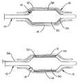
- FIG. 4is a side view of the balloon protector and balloon catheter of FIG. 1 shown during the outward pulling of the tube ends;
- FIG. 5is a side view of the balloon protector and balloon catheter of FIG. 5 shown subsequent to the tube ends being drawn to a predetermined extent;
- FIG. 6is side view of another embodiment of the balloon protector
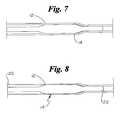
- FIG.7is a side view of an embodiment of the balloon protector and balloon catheter of FIG. 1 shown during the outward pulling of a tube end;
- FIG. 8is a side view of the balloon protector and balloon catheter of FIG. 7 shown subsequent to the tube end being drawn to a predetermined extent.
- the present balloon protectormay typically be constructed from extrudable materials such as polyether-polyester block copolymers.
- the balloon protectoris constructed from Arnitel® EM-740, however other materials which provide the necessary protective qualities and draw down capabilities as described in detail below, may also be used.
- the materialwill typically be extruded directly in tubular form or will be extruded as a film which may then be shaped into a tube.
- the diameter of the tubewill have an inside diameter substantially equal to or larger than the outside diameter of a balloon catheter and its associated devices, such as a stent, in the pre-insertion or reduced configuration.
- the tubemay be extruded directly as a tube, the tube may be affixed to a die, the die provides a guide for inserting the balloon catheter into the tube.
- the materialis a sheet or film, the material may be formed into a tube directly around the balloon catheter.
- FIG. 1shows a balloon catheter 10 within the tubular balloon protector 12 prior to drawing the balloon protector down.
- the catheter 10includes an inflatable portion or balloon 30 which has been folded into the pre-insertion or reduced configuration.
- the catheter 10may be configured for delivery of a stent or other device.
- the catheterincludes a stent 32 as well as a pair of stent retaining sleeves 34 .
- the cathetercould also be configured for delivery of a self-expanding stent 32 , and include a stent retaining sheath 36 and a pull back member 38 such as may be seen in FIG. 3 .
- the outside surface of the catheter 10 , the inside diameter 18 of the tube 12 , or both surfaces in combinationare treated with a lubrication.
- both the catheter 10 and the inside diameter 18have a slip coat applied prior to insertion of the catheter 10 into the tube 12 .
- the addition of lubrication to the catheter or tubeallows the balloon protector to be more readily removed from the catheter, by sliding the balloon protector distally off of the catheter prior to insertion of the catheter into a body vessel.
- the lubricationis preferably biocompatible.
- the balloon protector 12includes a kinked or deformed area 14 which in the embodiment shown defines a radial ‘V’ around a portion of the balloon protector's outside diameter 16 .
- a kinked area 14which in the embodiment shown defines a radial ‘V’ around a portion of the balloon protector's outside diameter 16 .
- a wide variety of methodsmay be incorporated to produce the kinked area 14 , such as through the application of a kinking tool as is known in the art. If desired, the kinked area 14 could alternatively be placed on the inside diameter 18 of the protector 12 or both the inside 18 and outside 16 diameters. The only requirement of the method selected is that it produce a ‘kink’ which provides a localized weakening in the wall of the protector 12 .
- Some examples of methods which could be used to form the kink 14may include: mechanical kinking such as by forming a shallow incision with a bladed device around the tube and/or the momentary application of depressive force at the desired location such as with a clamping tool; hand kinking by simply bending the tube at the desired location; thinning the desired area of the tube where the kink is to be formed in the extrusion process; or even heat treating the specific area of the protector to weaken the wall as desired.
- Other methods of forming the kink 14may be known, such methods may also be used to form the kinked area as desired.
- the kink 14is made at any time prior to placing the protector 12 over the balloon catheter 10 . More preferably, the kink 14 is made during the process of manufacturing of the protector 12 .
- the kinked area 14provides a localized and uniform weakening of the protector 12 .
- the protectormay be drawn down.
- the protectormay be drawn down in a number of ways. As may be seen in the embodiment shown in FIG. 4, the ends 20 and 22 of the protector 12 are pulled or drawn outwardly. End 20 is pulled proximally and end 22 is pulled distally away from the balloon 30 with a uniform rate and force as indicated by arrows 24 . As the ends 20 and 22 are pulled, the kinked area 14 will expand longitudinally and draw radially inward (i.e. draw down) toward the catheter 10 .
- the protector 12may be kinked at or near either end 20 or 22 , such as is end 22 shown, in FIG. 7 .
- the remaining end 20 of the protector 12is then secured or otherwise immobilized about the catheter 10 .
- the end 22may be pulled or drawn outwardly away from the balloon 30 as indicated by arrow 24 .
- the kinked area 14will propagate in the direction opposite the direction of the pull.
- the drawn down profile of the protector 12which is the result of the propagation of the kinked area 14 may best be seen in FIG. 8, which shows the completed propagation of the kinked area 14 throughout the length of the protector 12 .
- the extent of the draw down of the kinked areamay be best expressed as a percentage based on the ratio of the starting inside diameter 18 of the protector tube 12 prior to pulling ends 20 and 22 , such as shown in FIG. 1; verses the inside diameter 18 after the ends 20 and 22 are pulled to a predetermined extent and at a predetermined rate, such as shown in FIG. 5 .
- the draw down ratio of the balloon protector 12may range from 5% to 60%.
- the wall thicknessmay range from 0.001 to 0.05 inches.
- the rate at which the ends 20 and 22 are pulledalso affects the extent of the draw down. In order to achieve a consistent and effective draw down percentage, an end of the protector 12 or, the ends 20 and 22 must be pulled at a constant rate. However, if the rate of pull on ends 20 and 22 is increased, it may be possible to increase the draw down percentage by as much as 3-10 percent than the draw down percentage would otherwise be.
- a constant pull rateis desirable, in that it provides a draw down with predictable characteristics and which will ensure that the protector wall is not torn or ruptured during the pulling process.
- the inside diameter 18 of the protector 12will be drawn down against the catheter 10 .
- the present balloon protector 12has a sufficient draw down percentage and inherent radial strength to contact and retain balloon catheter 10 in the reduced state.
- any excess tube material at the distal end 22 of the tube 12 which exceeds the length of the catheter 10may be trimmed away.
- the balloon protector 12may assist in maintaining a sterile environment about the balloon protector.
- the distal end 22has been closed and sealed.
- the balloon protector end 22may be sealed such as by application of an adhesive to the inner diameter 18 of end 22 or by simply heat sealing the same. Other methods of sealing a tube are known in the art and may used as well as those described herein.
- the remaining balloon protector materialmost notably end 20 , will retain sufficient tension around the catheter 10 to remain in place subsequent to the pulling stage described above.
- the balloon protector 12provides the catheter 10 with a protective shield of resilient and flexible material which helps to prevent damage to the balloon catheter prior to use.
Landscapes
- Health & Medical Sciences (AREA)
- Heart & Thoracic Surgery (AREA)
- Life Sciences & Earth Sciences (AREA)
- General Health & Medical Sciences (AREA)
- Public Health (AREA)
- Veterinary Medicine (AREA)
- Vascular Medicine (AREA)
- Engineering & Computer Science (AREA)
- Animal Behavior & Ethology (AREA)
- Biomedical Technology (AREA)
- Hematology (AREA)
- Anesthesiology (AREA)
- Pulmonology (AREA)
- Child & Adolescent Psychology (AREA)
- Biophysics (AREA)
- Cardiology (AREA)
- Oral & Maxillofacial Surgery (AREA)
- Transplantation (AREA)
- Materials For Medical Uses (AREA)
Abstract
Description
Not Applicable
Not Applicable
Percutaneous transluminal coronary angioplasty (PTCA) is a procedure which is well established for the treatment of blockages in the coronary arteries. Blockages may occur from cholesterol precipitation on the coronary wall which may be in any stage from initial deposit through aged lesions. Coronary arteries may also become blocked due to formation of thrombus.
The most widely used form of percutaneous coronary angioplasty makes use of a dilatation balloon catheter. In typical PTCA procedures, the cardiovascular system of a patient is accessed with an introducer, usually in the groin area. All other devices including a guiding catheter are percutaneously introduced into the cardiovascular system of a patient through the introducer and advanced through a vessel until the distal end thereof is at a desired location in the vasculature. A guide wire and a dilatation catheter having a balloon on the distal end thereof are introduced through the guiding catheter with the guide wire sliding through the dilatation catheter. The guide wire is first advanced out of the guiding catheter into the patient's coronary vasculature and the dilatation catheter is advanced over the previously advanced guide wire until the dilatation balloon is properly positioned across the lesion. Once in position across the lesion, the flexible, expandable, preformed balloon is inflated to a predetermined size with a fluid at relatively high pressures, such as greater than about four atmospheres, to radially compress the atherosclerotic plaque of the lesion against the inside of the artery wall and thereby dilate the lumen of the artery. The balloon is then deflated to a small profile so that the dilatation catheter may be withdrawn from the patients vasculature and blood flow resumed through the dilated artery.
In angioplasty procedures of the kind described above, there may be restenosis of the artery, which either necessitates another angioplasty procedure, a surgical by-pass operation, or some method of repairing or strengthening the area. To reduce restenosis and strengthen the area, a physician can implant an intravascular prosthesis for maintaining vascular patency, called a stent, inside the artery at the lesion. In general, stents are prosthetic devices which can be positioned within a body cavity, for example, a blood vessel of the body of a living human or in some other difficulty accessible place. A stent generally has a diameter which may be increased or decreased. Stents are particularly useful for permanently widening a vessel which is in a narrowed state, or for internally supporting a vessel damaged by an aneurysm.
Such stents are typically introduced into the body cavity by use of a catheter. The catheter is usually of the balloon catheter type in which the balloon is utilized to expand the stent, which is positioned over the balloon, to place it in a selected location in the body cavity. The stent is expanded to a larger diameter for placement in the vasculature, often by the balloon portion of the catheter.
One important characteristic of a dilatation balloon catheter is its “profile”, which is determined by the outer diameter (O.D.) of the distal end portion of the balloon and stent when deflated. The outer diameter affects the ease and ability of the dilatation catheter to pass through a guide catheter, through the coronary arteries, and across a tight lesion.
Minimization of “profile” is of importance in balloon catheters and stent delivery systems. Accordingly, the present invention is particularly directed to a novel balloon protector which retains the balloon catheter in a reduced configuration prior to insertion of the catheter into a body lumen. The balloon protector of the present invention is suitable for use with a balloon catheter equipped with or without a stent.
A second important characteristic of a dilation balloon catheter is preventing damage to the catheter prior to insertion. It is known in the percutaneous balloon delivery art that the balloon or inflatable portion of a catheter may be easily damaged or ruptured prior to insertion into the body. Furthermore, preparation and associated manipulation of the balloon and /or stent prior to catheter insertion may impair balloon performance and possibly compromise the otherwise sterile condition of the catheter surface.
Protecting the catheter, especially the balloon, from damage and maintaining a sterile field about the catheter prior to insertion is of significant importance in any medical procedure involving a catheter. Accordingly the present invention is also directed to a novel balloon protector which has sufficiently strong and thick walls to protect the balloon from damage such as accidental puncture and that may be fitted over a balloon catheter with or without a stent, immediately after manufacturing and preparing the catheter for use.
The present invention is directed to a balloon protector for use an a variety of balloon catheter types. More specifically, the present invention is directed to a protector tube having a pre-kinked portion. A sterile balloon catheter is drawn through a die containing the tube, the ends of the tube are then drawn outwardly thereby drawing the pre-kinked area of the tube down against the balloon catheter.
This invention provides for a diameter reducing balloon protector for use in shielding the various components of an implantable balloon catheter from damage such as puncture, as well as for providing the balloon catheter with a maintainable sterile field prior to use. The present balloon protector when drawn down about a balloon catheter has sufficient strength and thickness to maintain the balloon catheter (and an associated stent if desired) in a reduced configuration prior to inserting the catheter into a body lumen. The present balloon protector may be easily fitted to nearly any variety or size of balloon catheter with minimal cost and effort.
In order to provide the balloon protector with a means of being removed from the balloon catheter, the inside diameter of the balloon protector may be treated with a variety of lubrications such as a slip coat.
A detailed description of the invention is hereafter described with specific reference being made to the drawings in which:
FIG. 1 is a side view of the balloon protector tube immediately after a balloon catheter has been inserted therein;
FIG. 2 is a side view of the balloon protector tube of FIG. 1 wherein the catheter is equipped with a balloon expandable stent;
FIG. 3 is a side view of the balloon protector tube of FIG. 1 wherein the catheter is equipped with a self-expanding stent;
FIG. 4 is a side view of the balloon protector and balloon catheter of FIG. 1 shown during the outward pulling of the tube ends;
FIG. 5 is a side view of the balloon protector and balloon catheter of FIG. 5 shown subsequent to the tube ends being drawn to a predetermined extent;
FIG. 6 is side view of another embodiment of the balloon protector;
FIG.7 is a side view of an embodiment of the balloon protector and balloon catheter of FIG. 1 shown during the outward pulling of a tube end; and
FIG. 8 is a side view of the balloon protector and balloon catheter of FIG. 7 shown subsequent to the tube end being drawn to a predetermined extent.
The present balloon protector may typically be constructed from extrudable materials such as polyether-polyester block copolymers. Preferably, the balloon protector is constructed from Arnitel® EM-740, however other materials which provide the necessary protective qualities and draw down capabilities as described in detail below, may also be used.
Whatever material is selected for use, the material will typically be extruded directly in tubular form or will be extruded as a film which may then be shaped into a tube. The diameter of the tube will have an inside diameter substantially equal to or larger than the outside diameter of a balloon catheter and its associated devices, such as a stent, in the pre-insertion or reduced configuration. Where the tube is extruded directly as a tube, the tube may be affixed to a die, the die provides a guide for inserting the balloon catheter into the tube. Where the material is a sheet or film, the material may be formed into a tube directly around the balloon catheter.
FIG. 1 shows aballoon catheter 10 within thetubular balloon protector 12 prior to drawing the balloon protector down.
Thecatheter 10 includes an inflatable portion orballoon 30 which has been folded into the pre-insertion or reduced configuration. In an alternative embodiment thecatheter 10 may be configured for delivery of a stent or other device.
In the embodiment shown in FIG. 2 the catheter includes astent 32 as well as a pair ofstent retaining sleeves 34. The catheter could also be configured for delivery of a self-expandingstent 32, and include astent retaining sheath 36 and apull back member 38 such as may be seen in FIG.3.
In the various embodiments of the present invention, prior to inserting thecatheter 10 into thetube 12, the outside surface of thecatheter 10, theinside diameter 18 of thetube 12, or both surfaces in combination are treated with a lubrication. In a preferred embodiment both thecatheter 10 and theinside diameter 18 have a slip coat applied prior to insertion of thecatheter 10 into thetube 12. The addition of lubrication to the catheter or tube allows the balloon protector to be more readily removed from the catheter, by sliding the balloon protector distally off of the catheter prior to insertion of the catheter into a body vessel. The lubrication is preferably biocompatible.
As may be seen in FIGS. 1-3, theballoon protector 12 includes a kinked ordeformed area 14 which in the embodiment shown defines a radial ‘V’ around a portion of the balloon protector'soutside diameter 16. A wide variety of methods may be incorporated to produce the kinkedarea 14, such as through the application of a kinking tool as is known in the art. If desired, the kinkedarea 14 could alternatively be placed on theinside diameter 18 of theprotector 12 or both the inside18 and outside16 diameters. The only requirement of the method selected is that it produce a ‘kink’ which provides a localized weakening in the wall of theprotector 12. Some examples of methods which could be used to form thekink 14 may include: mechanical kinking such as by forming a shallow incision with a bladed device around the tube and/or the momentary application of depressive force at the desired location such as with a clamping tool; hand kinking by simply bending the tube at the desired location; thinning the desired area of the tube where the kink is to be formed in the extrusion process; or even heat treating the specific area of the protector to weaken the wall as desired. Other methods of forming thekink 14 may be known, such methods may also be used to form the kinked area as desired.
Preferably, thekink 14 is made at any time prior to placing theprotector 12 over theballoon catheter 10. More preferably, thekink 14 is made during the process of manufacturing of theprotector 12.
As previously stated, the kinkedarea 14 provides a localized and uniform weakening of theprotector 12. Once the reducedcatheter 10 has been inserted into theballoon protector 12, the protector may be drawn down. The protector may be drawn down in a number of ways. As may be seen in the embodiment shown in FIG. 4, the ends20 and22 of theprotector 12 are pulled or drawn outwardly.End 20 is pulled proximally and end22 is pulled distally away from theballoon 30 with a uniform rate and force as indicated byarrows 24. As the ends20 and22 are pulled, the kinkedarea 14 will expand longitudinally and draw radially inward (i.e. draw down) toward thecatheter 10.
Alternatively, theprotector 12 may be kinked at or near either end20 or22, such as isend 22 shown, in FIG.7. The remainingend 20 of theprotector 12 is then secured or otherwise immobilized about thecatheter 10. Theend 22 may be pulled or drawn outwardly away from theballoon 30 as indicated byarrow 24. When the end of theprotector 12 includes the kinkedarea 14 and the end is then pulled in the appropriate direction away from theballoon 30, the kinkedarea 14 will propagate in the direction opposite the direction of the pull. The drawn down profile of theprotector 12 which is the result of the propagation of the kinkedarea 14 may best be seen in FIG. 8, which shows the completed propagation of the kinkedarea 14 throughout the length of theprotector 12.
The extent of the draw down of the kinked area may be best expressed as a percentage based on the ratio of the starting insidediameter 18 of theprotector tube 12 prior to pulling ends20 and22, such as shown in FIG. 1; verses theinside diameter 18 after the ends20 and22 are pulled to a predetermined extent and at a predetermined rate, such as shown in FIG.5. The draw down ratio of theballoon protector 12 may range from 5% to 60%.
The most significant factor which affects the extent of the draw down is the thickness of thetube walls 13. The wall thickness may range from 0.001 to 0.05 inches.
The rate at which the ends20 and22 are pulled also affects the extent of the draw down. In order to achieve a consistent and effective draw down percentage, an end of theprotector 12 or, the ends20 and22 must be pulled at a constant rate. However, if the rate of pull on ends20 and22 is increased, it may be possible to increase the draw down percentage by as much as 3-10 percent than the draw down percentage would otherwise be. A constant pull rate is desirable, in that it provides a draw down with predictable characteristics and which will ensure that the protector wall is not torn or ruptured during the pulling process.
As may be seen in FIG. 5, when the ends20 and22 have been pulled at the proper rate for a desired amount of time, theinside diameter 18 of theprotector 12 will be drawn down against thecatheter 10. Thepresent balloon protector 12 has a sufficient draw down percentage and inherent radial strength to contact and retainballoon catheter 10 in the reduced state.
When the balloon protector is drawn to the desired extent any excess tube material at thedistal end 22 of thetube 12 which exceeds the length of thecatheter 10 may be trimmed away.
In the embodiment shown in FIG. 6, theballoon protector 12 may assist in maintaining a sterile environment about the balloon protector. In this embodiment thedistal end 22 has been closed and sealed. Theballoon protector end 22 may be sealed such as by application of an adhesive to theinner diameter 18 ofend 22 or by simply heat sealing the same. Other methods of sealing a tube are known in the art and may used as well as those described herein.
The remaining balloon protector material, most notably end20, will retain sufficient tension around thecatheter 10 to remain in place subsequent to the pulling stage described above.
In all of the various embodiments shown and described above, theballoon protector 12 provides thecatheter 10 with a protective shield of resilient and flexible material which helps to prevent damage to the balloon catheter prior to use.
In addition to being directed to the embodiments described above and claimed below, the present invention is further directed to embodiments having different combinations of the features described above and claimed below. As such, the invention is also directed to other embodiments having any other possible combination of the dependent features claimed below.
The above examples and disclosure are intended to be illustrative arid not exhaustive. These examples and description will suggest many variations and alternatives to one of ordinary skill in this art. All these alternatives and variations are intended to be included within the scope of the attached claims. Those familiar with the art may recognize other equivalents to the specific embodiments described herein which equivalents are also intended to be encompassed by the claims attached hereto.
Claims (13)
1. A balloon protector comprising a tube of synthetic material, the tube having an unreduced state and a reduced state, the tube having an inside diameter and an outside diameter, the inside diameter having a catheter inserted therein, the catheter including an inflatable portion, at least the outside diameter of the tube having a kinked portion, the tube further having a proximal end and a distal end, in the reduced state at least a portion of the inside diameter of the tube which corresponds to the kinked portion of the tube being drawn inwardly down and about at least the expandable portion of the catheter and retaining the catheter in a reduced configuration, the tube constructed and arranged to be placed in the reduced state by pulling at least one end of the tube longitudinally in a direction away from at least the expandable portion of the catheter.
2. The balloon protector ofclaim 1 further comprising a lubricant, the lubricant applied to the inside diameter of the tube.
3. The balloon protector ofclaim 1 further comprising a lubricant, the lubricant applied to the catheter.
4. The balloon protector ofclaim 1 further comprising a lubricant, the lubricant applied to the inside diameter of the tube and the catheter.
5. The balloon protector ofclaim 4 wherein the lubricant is a slip coat.
6. The balloon protector ofclaim 1 wherein the catheter further comprises one or more implantable devices.
7. The balloon protector ofclaim 6 wherein the one or more implantable devices is a stent.
8. The balloon protector ofclaim 1 wherein the tube has a thickness of 0.001 to 0.05 inches.
9. The balloon protector ofclaim 1 wherein the portion of the tube being drawn down and about at least the expandable portion of the catheter is drawn down 5 to 60 percent relative to the portion of the tube which is not drawn down.
10. The balloon protector ofclaim 1 wherein the tube is constructed from one or more polyether-polyester block copolymers.
11. The balloon protector ofclaim 1 wherein the tube is constructed from Arnitel EM-740.
12. A method for protecting a balloon catheter comprising the steps of:
providing a tube constructed from one or more polyether-polyester block copolymers, the tube having an inside diameter and an outside diameter, the tube having a proximal end and a distal end;
kinking a predetermined area of the tube;
inserting a catheter within the inside diameter of the tube, the catheter having a proximal catheter end and a distal catheter end, the catheter further having at least one inflatable portion at the distal catheter end;
drawing the predetermined area of the tube inward toward and against the catheter by pulling at least one end of the tube longitudinally in a direction away from the inflatable portion of the catheter, at a predetermined rate, for a predetermined length of time.
13. The method for protecting a balloon catheter ofclaim 12 further comprising the step of:
trimming the distal end of the tube which exceeds the distal catheter end, and
sealing the distal end of the tube.
Priority Applications (1)
| Application Number | Priority Date | Filing Date | Title |
|---|---|---|---|
| US09/587,769US6613067B1 (en) | 2000-06-06 | 2000-06-06 | Balloon protector |
Applications Claiming Priority (1)
| Application Number | Priority Date | Filing Date | Title |
|---|---|---|---|
| US09/587,769US6613067B1 (en) | 2000-06-06 | 2000-06-06 | Balloon protector |
Publications (1)
| Publication Number | Publication Date |
|---|---|
| US6613067B1true US6613067B1 (en) | 2003-09-02 |
Family
ID=27766414
Family Applications (1)
| Application Number | Title | Priority Date | Filing Date |
|---|---|---|---|
| US09/587,769Expired - LifetimeUS6613067B1 (en) | 2000-06-06 | 2000-06-06 | Balloon protector |
Country Status (1)
| Country | Link |
|---|---|
| US (1) | US6613067B1 (en) |
Cited By (38)
| Publication number | Priority date | Publication date | Assignee | Title |
|---|---|---|---|---|
| US20030004534A1 (en)* | 2001-06-01 | 2003-01-02 | George Stephanie A. | Balloon transporter |
| US20060016478A1 (en)* | 2004-07-21 | 2006-01-26 | Vinit Chantalat | Bending sleeve clamp for controlling fluid flow in a flexible tube |
| US7225518B2 (en) | 2004-02-23 | 2007-06-05 | Boston Scientific Scimed, Inc. | Apparatus for crimping a stent assembly |
| US7314480B2 (en) | 2003-02-27 | 2008-01-01 | Boston Scientific Scimed, Inc. | Rotating balloon expandable sheath bifurcation delivery |
| US20080033476A1 (en)* | 2006-08-07 | 2008-02-07 | Greene Joel M | Catheter balloon with controlled failure sheath |
| US20080051819A1 (en)* | 2006-08-25 | 2008-02-28 | Nishith Chasmawala | Apparatus and methods for use of expandable members in surgical applications |
| US20080086192A1 (en)* | 2006-10-10 | 2008-04-10 | Boston Scientific Scimed, Inc. | Stent protector design |
| US7367989B2 (en) | 2003-02-27 | 2008-05-06 | Scimed Life Systems, Inc. | Rotating balloon expandable sheath bifurcation delivery |
| US20100049297A1 (en)* | 2008-08-21 | 2010-02-25 | C.R. Bard, Inc. | Method of loading a stent into a sheath |
| US7686841B2 (en) | 2003-12-29 | 2010-03-30 | Boston Scientific Scimed, Inc. | Rotating balloon expandable sheath bifurcation delivery system |
| US7744619B2 (en) | 2004-02-24 | 2010-06-29 | Boston Scientific Scimed, Inc. | Rotatable catheter assembly |
| CH700826B1 (en)* | 2007-05-22 | 2010-10-29 | Schwager Medica | Catheter for therapeutic or diagnostic purposes in e.g. human hollow organs or vessels, has sheath including insertion channel provided as insertion aid for guide wire in catheter tip area, where channel is located at guide wire opening |
| US20100318113A1 (en)* | 1993-10-01 | 2010-12-16 | Boston Scientific Scimed, Inc. | Medical Device Balloons Containing Thermoplastic Elastomers |
| US20110060397A1 (en)* | 2008-05-09 | 2011-03-10 | C.R. Bard, Inc. | Method of loading a stent into a sheath |
| US7922740B2 (en) | 2004-02-24 | 2011-04-12 | Boston Scientific Scimed, Inc. | Rotatable catheter assembly |
| US7922753B2 (en) | 2004-01-13 | 2011-04-12 | Boston Scientific Scimed, Inc. | Bifurcated stent delivery system |
| US20110100086A1 (en)* | 2004-02-26 | 2011-05-05 | Boston Scientific Scimed, Inc. | Crimper |
| US20110137402A1 (en)* | 2009-12-03 | 2011-06-09 | C. R. Bard, Inc. | Stent device delivery system with a heat shrink resistant support member |
| US20110137400A1 (en)* | 2009-12-03 | 2011-06-09 | C. R. Bard, Inc. | Stent device delivery system with a varying radial profile pull member |
| US8012192B2 (en) | 2004-02-18 | 2011-09-06 | Boston Scientific Scimed, Inc. | Multi-stent delivery system |
| US8133199B2 (en) | 2008-08-27 | 2012-03-13 | Boston Scientific Scimed, Inc. | Electroactive polymer activation system for a medical device |
| US20120285662A1 (en)* | 2011-05-10 | 2012-11-15 | Celsia Technologies Taiwan, I | Vapor chamber with improved sealed opening |
| US8333003B2 (en) | 2008-05-19 | 2012-12-18 | Boston Scientific Scimed, Inc. | Bifurcation stent crimping systems and methods |
| US20130253466A1 (en)* | 2011-06-23 | 2013-09-26 | Carey V. Campbell | Controllable inflation profile balloon cover apparatus and methods |
| US8784472B2 (en) | 2003-08-15 | 2014-07-22 | Boston Scientific Scimed, Inc. | Clutch driven stent delivery system |
| US8926620B2 (en) | 2006-08-25 | 2015-01-06 | Kyphon Sarl | Apparatus and methods for use of expandable members in surgical applications |
| US9168164B2 (en) | 2010-12-01 | 2015-10-27 | C. R. Bard, Inc. | Device to release a self-expanding implant |
| WO2016050303A1 (en)* | 2014-10-02 | 2016-04-07 | Alexander Rübben | Cutback method for intravascular dilation catheter |
| US9387101B2 (en) | 2007-10-17 | 2016-07-12 | C.R. Bard, Inc. | Delivery system for a self-expanding device for placement in a bodily lumen |
| CN106551741A (en)* | 2016-11-09 | 2017-04-05 | 恩脉(上海)医疗科技有限公司 | A kind of load medicine apparatus protection device for being easy in vivo withdraw |
| US9687369B2 (en) | 2009-12-03 | 2017-06-27 | C.R. Bard, Inc. | Stent device delivery system with an outer sheath polymeric reinforcement layer |
| US9724216B2 (en) | 2009-12-03 | 2017-08-08 | C. R. Bard, Inc. | Stent device delivery system with inwardly tapering stent bed |
| US10271979B2 (en) | 2008-12-31 | 2019-04-30 | C. R . Bard, Inc. | Stent delivery device with rolling stent retaining sheath |
| US10449335B2 (en) | 2013-05-03 | 2019-10-22 | C.R. Bard, Inc. | Peelable protective sheath |
| CN110548210A (en)* | 2019-10-09 | 2019-12-10 | 四川省肿瘤医院 | Catheter capable of preventing edges and corners formed by pressure loss from damaging urethra |
| US11389627B1 (en) | 2018-10-02 | 2022-07-19 | Lutonix Inc. | Balloon protectors, balloon-catheter assemblies, and methods thereof |
| US12167961B2 (en) | 2020-08-24 | 2024-12-17 | Edwards Lifesciences Corporation | Methods and systems for aligning a commissure of a prosthetic heart valve with a commissure of a native valve |
| US12290436B2 (en) | 2016-08-01 | 2025-05-06 | Edwards Lifesciences Corporation | Prosthetic heart valve |
Citations (33)
| Publication number | Priority date | Publication date | Assignee | Title |
|---|---|---|---|---|
| US4702252A (en)* | 1983-10-13 | 1987-10-27 | Smiths Industries Public Limited Company | Catheters |
| US4796629A (en)* | 1987-06-03 | 1989-01-10 | Joseph Grayzel | Stiffened dilation balloon catheter device |
| US4846174A (en)* | 1986-08-08 | 1989-07-11 | Scimed Life Systems, Inc. | Angioplasty dilating guide wire |
| US4921479A (en) | 1987-10-02 | 1990-05-01 | Joseph Grayzel | Catheter sheath with longitudinal seam |
| US5015231A (en) | 1989-04-21 | 1991-05-14 | Scimed Life Systems, Inc. | Multipart split sleeve balloon protector for dilatation catheter |
| US5053007A (en) | 1989-12-14 | 1991-10-01 | Scimed Life Systems, Inc. | Compression balloon protector for a balloon dilatation catheter and method of use thereof |
| US5066298A (en) | 1989-11-30 | 1991-11-19 | Progressive Angioplasty Systems, Inc. | Article and method of sheathing angioplasty balloons |
| US5137512A (en) | 1989-03-17 | 1992-08-11 | Scimed Life Systems, Inc. | Multisegment balloon protector for dilatation catheter |
| US5211654A (en)* | 1990-06-09 | 1993-05-18 | Martin Kaltenbach | Catheter with expansible distal end |
| US5334146A (en)* | 1990-11-10 | 1994-08-02 | Terumo Kabushiki Kaisha | Catheter balloon having varying wall thickness |
| US5352236A (en) | 1992-09-29 | 1994-10-04 | Medtronic, Inc. | Balloon protector |
| US5417707A (en) | 1993-10-29 | 1995-05-23 | Medtronic, Inc. | Dilatation balloon protector with raised ribs |
| US5425710A (en)* | 1993-10-26 | 1995-06-20 | Medtronic, Inc. | Coated sleeve for wrapping dilatation catheter balloons |
| US5443495A (en)* | 1993-09-17 | 1995-08-22 | Scimed Lifesystems Inc. | Polymerization angioplasty balloon implant device |
| US5556383A (en)* | 1994-03-02 | 1996-09-17 | Scimed Lifesystems, Inc. | Block copolymer elastomer catheter balloons |
| US5569294A (en) | 1994-09-26 | 1996-10-29 | Medtronic, Inc. | Two piece balloon protector |
| US5613979A (en)* | 1989-11-29 | 1997-03-25 | Cordis Corporation | Puncture resistant balloon catheter |
| US5735859A (en) | 1997-02-14 | 1998-04-07 | Cathco, Inc. | Distally attachable and releasable sheath for a stent delivery system |
| US5807327A (en)* | 1995-12-08 | 1998-09-15 | Ethicon, Inc. | Catheter assembly |
| US5868707A (en) | 1996-08-15 | 1999-02-09 | Advanced Cardiovascular Systems, Inc. | Protective sheath for catheter balloons |
| US5893868A (en) | 1997-03-05 | 1999-04-13 | Scimed Life Systems, Inc. | Catheter with removable balloon protector and stent delivery system with removable stent protector |
| US5961536A (en)* | 1997-10-14 | 1999-10-05 | Scimed Life Systems, Inc. | Catheter having a variable length balloon and method of using the same |
| US5968069A (en)* | 1996-08-23 | 1999-10-19 | Scimed Life Systems, Inc. | Stent delivery system having stent securement apparatus |
| US5993424A (en)* | 1996-08-05 | 1999-11-30 | Cordis Corporation | Guidewire having a distal tip that can change its shape within a vessel |
| US6110146A (en) | 1998-09-30 | 2000-08-29 | Medtronic Ave, Inc. | Protector for catheter balloon with guidewire backloading system |
| US6124007A (en)* | 1996-03-06 | 2000-09-26 | Scimed Life Systems Inc | Laminate catheter balloons with additive burst strength and methods for preparation of same |
| US6152944A (en)* | 1997-03-05 | 2000-11-28 | Scimed Life Systems, Inc. | Catheter with removable balloon protector and stent delivery system with removable stent protector |
| US6159244A (en) | 1999-07-30 | 2000-12-12 | Suddaby; Loubert | Expandable variable angle intervertebral fusion implant |
| US6168748B1 (en)* | 1995-03-02 | 2001-01-02 | Scimed Life Systems, Inc. | Method of balloon formation by cold drawing/necking |
| US6168617B1 (en)* | 1999-06-14 | 2001-01-02 | Scimed Life Systems, Inc. | Stent delivery system |
| US6176849B1 (en)* | 1999-05-21 | 2001-01-23 | Scimed Life Systems, Inc. | Hydrophilic lubricity coating for medical devices comprising a hydrophobic top coat |
| US20020032406A1 (en)* | 1996-10-10 | 2002-03-14 | Kusleika Richard S. | Catheter for tissue dilatation and drug delivery |
| US6447540B1 (en)* | 1996-11-15 | 2002-09-10 | Cook Incorporated | Stent deployment device including splittable sleeve containing the stent |
- 2000
- 2000-06-06USUS09/587,769patent/US6613067B1/ennot_activeExpired - Lifetime
Patent Citations (35)
| Publication number | Priority date | Publication date | Assignee | Title |
|---|---|---|---|---|
| US4702252A (en)* | 1983-10-13 | 1987-10-27 | Smiths Industries Public Limited Company | Catheters |
| US4846174A (en)* | 1986-08-08 | 1989-07-11 | Scimed Life Systems, Inc. | Angioplasty dilating guide wire |
| US4796629A (en)* | 1987-06-03 | 1989-01-10 | Joseph Grayzel | Stiffened dilation balloon catheter device |
| US4921479A (en) | 1987-10-02 | 1990-05-01 | Joseph Grayzel | Catheter sheath with longitudinal seam |
| US5137512A (en) | 1989-03-17 | 1992-08-11 | Scimed Life Systems, Inc. | Multisegment balloon protector for dilatation catheter |
| US5015231A (en) | 1989-04-21 | 1991-05-14 | Scimed Life Systems, Inc. | Multipart split sleeve balloon protector for dilatation catheter |
| US5613979A (en)* | 1989-11-29 | 1997-03-25 | Cordis Corporation | Puncture resistant balloon catheter |
| US5066298A (en) | 1989-11-30 | 1991-11-19 | Progressive Angioplasty Systems, Inc. | Article and method of sheathing angioplasty balloons |
| US5053007A (en) | 1989-12-14 | 1991-10-01 | Scimed Life Systems, Inc. | Compression balloon protector for a balloon dilatation catheter and method of use thereof |
| US5211654A (en)* | 1990-06-09 | 1993-05-18 | Martin Kaltenbach | Catheter with expansible distal end |
| US5334146A (en)* | 1990-11-10 | 1994-08-02 | Terumo Kabushiki Kaisha | Catheter balloon having varying wall thickness |
| US5352236A (en) | 1992-09-29 | 1994-10-04 | Medtronic, Inc. | Balloon protector |
| US5443495A (en)* | 1993-09-17 | 1995-08-22 | Scimed Lifesystems Inc. | Polymerization angioplasty balloon implant device |
| US5425710A (en)* | 1993-10-26 | 1995-06-20 | Medtronic, Inc. | Coated sleeve for wrapping dilatation catheter balloons |
| US5417707A (en) | 1993-10-29 | 1995-05-23 | Medtronic, Inc. | Dilatation balloon protector with raised ribs |
| US5556383A (en)* | 1994-03-02 | 1996-09-17 | Scimed Lifesystems, Inc. | Block copolymer elastomer catheter balloons |
| US5569294A (en) | 1994-09-26 | 1996-10-29 | Medtronic, Inc. | Two piece balloon protector |
| US6168748B1 (en)* | 1995-03-02 | 2001-01-02 | Scimed Life Systems, Inc. | Method of balloon formation by cold drawing/necking |
| US5807327A (en)* | 1995-12-08 | 1998-09-15 | Ethicon, Inc. | Catheter assembly |
| US6124007A (en)* | 1996-03-06 | 2000-09-26 | Scimed Life Systems Inc | Laminate catheter balloons with additive burst strength and methods for preparation of same |
| US5993424A (en)* | 1996-08-05 | 1999-11-30 | Cordis Corporation | Guidewire having a distal tip that can change its shape within a vessel |
| US5868707A (en) | 1996-08-15 | 1999-02-09 | Advanced Cardiovascular Systems, Inc. | Protective sheath for catheter balloons |
| US5968069A (en)* | 1996-08-23 | 1999-10-19 | Scimed Life Systems, Inc. | Stent delivery system having stent securement apparatus |
| US20020032406A1 (en)* | 1996-10-10 | 2002-03-14 | Kusleika Richard S. | Catheter for tissue dilatation and drug delivery |
| US6447540B1 (en)* | 1996-11-15 | 2002-09-10 | Cook Incorporated | Stent deployment device including splittable sleeve containing the stent |
| US5735859A (en) | 1997-02-14 | 1998-04-07 | Cathco, Inc. | Distally attachable and releasable sheath for a stent delivery system |
| US5893868A (en) | 1997-03-05 | 1999-04-13 | Scimed Life Systems, Inc. | Catheter with removable balloon protector and stent delivery system with removable stent protector |
| US6132450A (en) | 1997-03-05 | 2000-10-17 | Scimed Life Systems, Inc. | Catheter with removable balloon protector |
| US6152944A (en)* | 1997-03-05 | 2000-11-28 | Scimed Life Systems, Inc. | Catheter with removable balloon protector and stent delivery system with removable stent protector |
| US20010001128A1 (en)* | 1997-03-05 | 2001-05-10 | Holman Thomas J. | Catheter with removable balloon protector and stent delivery system with removable stent protector |
| US5961536A (en)* | 1997-10-14 | 1999-10-05 | Scimed Life Systems, Inc. | Catheter having a variable length balloon and method of using the same |
| US6110146A (en) | 1998-09-30 | 2000-08-29 | Medtronic Ave, Inc. | Protector for catheter balloon with guidewire backloading system |
| US6176849B1 (en)* | 1999-05-21 | 2001-01-23 | Scimed Life Systems, Inc. | Hydrophilic lubricity coating for medical devices comprising a hydrophobic top coat |
| US6168617B1 (en)* | 1999-06-14 | 2001-01-02 | Scimed Life Systems, Inc. | Stent delivery system |
| US6159244A (en) | 1999-07-30 | 2000-12-12 | Suddaby; Loubert | Expandable variable angle intervertebral fusion implant |
Cited By (66)
| Publication number | Priority date | Publication date | Assignee | Title |
|---|---|---|---|---|
| US8025943B2 (en)* | 1993-10-01 | 2011-09-27 | Boston Scientific Scimed, Inc. | Medical device balloons containing thermoplastic elastomers |
| US20100318113A1 (en)* | 1993-10-01 | 2010-12-16 | Boston Scientific Scimed, Inc. | Medical Device Balloons Containing Thermoplastic Elastomers |
| US20120016405A1 (en)* | 1993-10-01 | 2012-01-19 | Boston Scientific Scimed, Inc. | Medical Device Balloons Containing Thermoplastic Elastomers |
| US20030004534A1 (en)* | 2001-06-01 | 2003-01-02 | George Stephanie A. | Balloon transporter |
| US7367989B2 (en) | 2003-02-27 | 2008-05-06 | Scimed Life Systems, Inc. | Rotating balloon expandable sheath bifurcation delivery |
| US7314480B2 (en) | 2003-02-27 | 2008-01-01 | Boston Scientific Scimed, Inc. | Rotating balloon expandable sheath bifurcation delivery |
| US8784472B2 (en) | 2003-08-15 | 2014-07-22 | Boston Scientific Scimed, Inc. | Clutch driven stent delivery system |
| US7686841B2 (en) | 2003-12-29 | 2010-03-30 | Boston Scientific Scimed, Inc. | Rotating balloon expandable sheath bifurcation delivery system |
| US7922753B2 (en) | 2004-01-13 | 2011-04-12 | Boston Scientific Scimed, Inc. | Bifurcated stent delivery system |
| US8012192B2 (en) | 2004-02-18 | 2011-09-06 | Boston Scientific Scimed, Inc. | Multi-stent delivery system |
| US7225518B2 (en) | 2004-02-23 | 2007-06-05 | Boston Scientific Scimed, Inc. | Apparatus for crimping a stent assembly |
| US7744619B2 (en) | 2004-02-24 | 2010-06-29 | Boston Scientific Scimed, Inc. | Rotatable catheter assembly |
| US8333784B2 (en) | 2004-02-24 | 2012-12-18 | Boston Scientific Scimed, Inc. | Rotatable catheter assembly |
| US7922740B2 (en) | 2004-02-24 | 2011-04-12 | Boston Scientific Scimed, Inc. | Rotatable catheter assembly |
| US8516871B2 (en) | 2004-02-26 | 2013-08-27 | Boston Scientific Scimed, Inc. | Crimper |
| US20110100086A1 (en)* | 2004-02-26 | 2011-05-05 | Boston Scientific Scimed, Inc. | Crimper |
| US20060016478A1 (en)* | 2004-07-21 | 2006-01-26 | Vinit Chantalat | Bending sleeve clamp for controlling fluid flow in a flexible tube |
| US20080033476A1 (en)* | 2006-08-07 | 2008-02-07 | Greene Joel M | Catheter balloon with controlled failure sheath |
| US8926620B2 (en) | 2006-08-25 | 2015-01-06 | Kyphon Sarl | Apparatus and methods for use of expandable members in surgical applications |
| US8043296B2 (en) | 2006-08-25 | 2011-10-25 | Kyphon Sarl | Apparatus and methods for use of expandable members in surgical applications |
| US20080051819A1 (en)* | 2006-08-25 | 2008-02-28 | Nishith Chasmawala | Apparatus and methods for use of expandable members in surgical applications |
| WO2008045156A1 (en)* | 2006-10-10 | 2008-04-17 | Boston Scientific Scimed, Inc. | Stent protector design |
| US9814557B2 (en)* | 2006-10-10 | 2017-11-14 | Boston Scientific Scimed, Inc. | Stent protector design |
| US10729526B2 (en) | 2006-10-10 | 2020-08-04 | Boston Scientific Scimed, Inc. | Stent protector design |
| US20080086192A1 (en)* | 2006-10-10 | 2008-04-10 | Boston Scientific Scimed, Inc. | Stent protector design |
| CH700826B1 (en)* | 2007-05-22 | 2010-10-29 | Schwager Medica | Catheter for therapeutic or diagnostic purposes in e.g. human hollow organs or vessels, has sheath including insertion channel provided as insertion aid for guide wire in catheter tip area, where channel is located at guide wire opening |
| US9387101B2 (en) | 2007-10-17 | 2016-07-12 | C.R. Bard, Inc. | Delivery system for a self-expanding device for placement in a bodily lumen |
| US9687370B2 (en)* | 2008-05-09 | 2017-06-27 | C.R. Bard, Inc. | Method of loading a stent into a sheath |
| US20110060397A1 (en)* | 2008-05-09 | 2011-03-10 | C.R. Bard, Inc. | Method of loading a stent into a sheath |
| US8333003B2 (en) | 2008-05-19 | 2012-12-18 | Boston Scientific Scimed, Inc. | Bifurcation stent crimping systems and methods |
| US20100049297A1 (en)* | 2008-08-21 | 2010-02-25 | C.R. Bard, Inc. | Method of loading a stent into a sheath |
| US9833349B2 (en)* | 2008-08-21 | 2017-12-05 | C. R. Bard, Inc. | Method of loading a stent into a sheath |
| US8133199B2 (en) | 2008-08-27 | 2012-03-13 | Boston Scientific Scimed, Inc. | Electroactive polymer activation system for a medical device |
| US10271979B2 (en) | 2008-12-31 | 2019-04-30 | C. R . Bard, Inc. | Stent delivery device with rolling stent retaining sheath |
| US9717612B2 (en) | 2009-12-03 | 2017-08-01 | C.R. Bard, Inc. | Stent device delivery system with a varying radial profile pull member |
| US20110137402A1 (en)* | 2009-12-03 | 2011-06-09 | C. R. Bard, Inc. | Stent device delivery system with a heat shrink resistant support member |
| US10278845B2 (en) | 2009-12-03 | 2019-05-07 | C. R. Bard, Inc. | Stent device delivery system with a heat shrink resistant support member |
| US9687369B2 (en) | 2009-12-03 | 2017-06-27 | C.R. Bard, Inc. | Stent device delivery system with an outer sheath polymeric reinforcement layer |
| US10555824B2 (en) | 2009-12-03 | 2020-02-11 | C. R. Bard, Inc. | Stent device delivery system with inwardly tapering stent bed |
| US10449072B2 (en) | 2009-12-03 | 2019-10-22 | C.R. Bard, Inc. | Stent device delivery system with an outer sheath polymeric reinforcement layer |
| US9724216B2 (en) | 2009-12-03 | 2017-08-08 | C. R. Bard, Inc. | Stent device delivery system with inwardly tapering stent bed |
| US20110137400A1 (en)* | 2009-12-03 | 2011-06-09 | C. R. Bard, Inc. | Stent device delivery system with a varying radial profile pull member |
| US10779975B2 (en) | 2009-12-03 | 2020-09-22 | C. R. Bard, Inc. | Stent device delivery system with a varying radial profile pull member |
| US9168164B2 (en) | 2010-12-01 | 2015-10-27 | C. R. Bard, Inc. | Device to release a self-expanding implant |
| US10821013B2 (en) | 2010-12-01 | 2020-11-03 | C. R. Bard, Inc. | Device to release a self-expanding implant |
| US20120285662A1 (en)* | 2011-05-10 | 2012-11-15 | Celsia Technologies Taiwan, I | Vapor chamber with improved sealed opening |
| US10016579B2 (en)* | 2011-06-23 | 2018-07-10 | W.L. Gore & Associates, Inc. | Controllable inflation profile balloon cover apparatus |
| US11173286B2 (en) | 2011-06-23 | 2021-11-16 | W. L. Gore & Associates, Inc. | Controllable inflation profile balloon cover methods |
| US20130253466A1 (en)* | 2011-06-23 | 2013-09-26 | Carey V. Campbell | Controllable inflation profile balloon cover apparatus and methods |
| KR20140062148A (en)* | 2011-09-16 | 2014-05-22 | 더블유.엘. 고어 앤드 어소시에이트스, 인코포레이티드 | Controllable inflation profile balloon cover apparatus and methods |
| US10449335B2 (en) | 2013-05-03 | 2019-10-22 | C.R. Bard, Inc. | Peelable protective sheath |
| CN107106819A (en)* | 2014-10-02 | 2017-08-29 | 雅辰科学国际私人有限公司 | The reduction method of intravascular dilation conduit |
| WO2016050303A1 (en)* | 2014-10-02 | 2016-04-07 | Alexander Rübben | Cutback method for intravascular dilation catheter |
| JP2017529962A (en)* | 2014-10-02 | 2017-10-12 | アーヘン サイエンティフィック インターナショナル ピーティーイー.リミテッド | Cutback method for endovascular dilatation catheters |
| US10653870B2 (en)* | 2014-10-02 | 2020-05-19 | Aachen Scientific International Pte. Ltd. | Cutback method for intravascular dilation catheter |
| US20170291015A1 (en)* | 2014-10-02 | 2017-10-12 | Aachen Scientific International Pte. Ltd. | Cutback Method for Intravascular Dilation Catheter |
| US12290436B2 (en) | 2016-08-01 | 2025-05-06 | Edwards Lifesciences Corporation | Prosthetic heart valve |
| CN106551741B (en)* | 2016-11-09 | 2019-01-04 | 恩脉(上海)医疗科技有限公司 | A kind of load medicine instrument protective device for being easy to withdraw in vivo |
| CN106551741A (en)* | 2016-11-09 | 2017-04-05 | 恩脉(上海)医疗科技有限公司 | A kind of load medicine apparatus protection device for being easy in vivo withdraw |
| US11389627B1 (en) | 2018-10-02 | 2022-07-19 | Lutonix Inc. | Balloon protectors, balloon-catheter assemblies, and methods thereof |
| CN110548210A (en)* | 2019-10-09 | 2019-12-10 | 四川省肿瘤医院 | Catheter capable of preventing edges and corners formed by pressure loss from damaging urethra |
| CN110548210B (en)* | 2019-10-09 | 2024-02-20 | 四川省肿瘤医院 | Catheter for preventing corner formed by decompression from damaging urethra |
| US12167961B2 (en) | 2020-08-24 | 2024-12-17 | Edwards Lifesciences Corporation | Methods and systems for aligning a commissure of a prosthetic heart valve with a commissure of a native valve |
| US12171655B2 (en) | 2020-08-24 | 2024-12-24 | Edwards Lifesciences Corporation | Methods and systems for aligning a commissure of a prosthetic heart valve with a commissure of a native valve |
| US12186181B2 (en) | 2020-08-24 | 2025-01-07 | Edwards Lifesciences Corporation | Balloon cover for a delivery apparatus for an expandable prosthetic heart valve |
| US12310843B2 (en) | 2020-08-24 | 2025-05-27 | Edwards Lifesciences Corporation | Balloon cover for a delivery apparatus for an expandable prosthetic heart valve |
Similar Documents
| Publication | Publication Date | Title |
|---|---|---|
| US6613067B1 (en) | Balloon protector | |
| US6132450A (en) | Catheter with removable balloon protector | |
| CA2163708C (en) | Integrated dual-function catheter system for balloon angioplasty and stent delivery | |
| US6193727B1 (en) | System for removably securing a stent on a catheter assembly and method of use | |
| US6110180A (en) | System for removably securing a stent on a catheter assembly and method of use | |
| US6613075B1 (en) | Rapid exchange self-expanding stent delivery catheter system | |
| US5476505A (en) | Coiled stent and delivery system | |
| US5662703A (en) | Rolling membrane stent delivery device | |
| JP4017677B2 (en) | Catheter with removable balloon protector and stent delivery system with removable stent protector | |
| US5980533A (en) | Stent delivery system | |
| US6592569B2 (en) | Protective sheath for catheters | |
| US6007543A (en) | Stent delivery system with stent securement means | |
| US6527741B1 (en) | Angioplasty catheter system with adjustable balloon length | |
| US6620191B1 (en) | System for releasably securing a stent on a catheter assembly and method of use | |
| US20080006554A1 (en) | Packaging assembly for a catheter | |
| EP0897730A2 (en) | Retainer for a stent-carrying balloon catheter | |
| WO2001017459A1 (en) | System for removably securing a stent on a catheter assembly and method of use | |
| US6447521B1 (en) | Foamed inner member cover stent retention and method of use | |
| CA2372820A1 (en) | Intravascular stent delivery assembly | |
| MXPA98006472A (en) | A retainer for globe cateter that transportsoprote | |
| AU6957900A (en) | Rapid exchange self-expanding stent delivery catheter system |
Legal Events
| Date | Code | Title | Description |
|---|---|---|---|
| AS | Assignment | Owner name:SCIMED LIFE SYSTEMS, INC., MINNESOTA Free format text:ASSIGNMENT OF ASSIGNORS INTEREST;ASSIGNOR:JOHNSON, MICHAEL W.;REEL/FRAME:010877/0886 Effective date:20000530 | |
| STCF | Information on status: patent grant | Free format text:PATENTED CASE | |
| FEPP | Fee payment procedure | Free format text:PAYOR NUMBER ASSIGNED (ORIGINAL EVENT CODE: ASPN); ENTITY STATUS OF PATENT OWNER: LARGE ENTITY | |
| AS | Assignment | Owner name:BOSTON SCIENTIFIC SCIMED, INC., MINNESOTA Free format text:CHANGE OF NAME;ASSIGNOR:SCIMED LIFE SYSTEMS, INC.;REEL/FRAME:018505/0868 Effective date:20050101 Owner name:BOSTON SCIENTIFIC SCIMED, INC.,MINNESOTA Free format text:CHANGE OF NAME;ASSIGNOR:SCIMED LIFE SYSTEMS, INC.;REEL/FRAME:018505/0868 Effective date:20050101 | |
| FPAY | Fee payment | Year of fee payment:4 | |
| FPAY | Fee payment | Year of fee payment:8 | |
| FPAY | Fee payment | Year of fee payment:12 |