US6613011B2 - Gas-pressured engine with valve - Google Patents
Gas-pressured engine with valveDownload PDFInfo
- Publication number
- US6613011B2 US6613011B2US10/099,846US9984602AUS6613011B2US 6613011 B2US6613011 B2US 6613011B2US 9984602 AUS9984602 AUS 9984602AUS 6613011 B2US6613011 B2US 6613011B2
- Authority
- US
- United States
- Prior art keywords
- valve
- engine
- valve stem
- engine housing
- guide
- Prior art date
- Legal status (The legal status is an assumption and is not a legal conclusion. Google has not performed a legal analysis and makes no representation as to the accuracy of the status listed.)
- Expired - Fee Related
Links
- 238000003908quality control methodMethods0.000claimsabstractdescription9
- 238000000034methodMethods0.000claimsabstract22
- 238000004519manufacturing processMethods0.000claimsabstract4
- 239000007789gasSubstances0.000claimsdescription52
- CURLTUGMZLYLDI-UHFFFAOYSA-NCarbon dioxideChemical compoundO=C=OCURLTUGMZLYLDI-UHFFFAOYSA-N0.000claimsdescription8
- 239000011261inert gasSubstances0.000claimsdescription6
- 229910002092carbon dioxideInorganic materials0.000claimsdescription5
- 239000001569carbon dioxideSubstances0.000claimsdescription5
- 239000000463materialSubstances0.000claimsdescription5
- XUIMIQQOPSSXEZ-UHFFFAOYSA-NSiliconChemical compound[Si]XUIMIQQOPSSXEZ-UHFFFAOYSA-N0.000claimsdescription3
- 125000000484butyl groupChemical group[H]C([*])([H])C([H])([H])C([H])([H])C([H])([H])[H]0.000claimsdescription3
- 238000004891communicationMethods0.000claimsdescription3
- 229910052710siliconInorganic materials0.000claimsdescription3
- 239000010703siliconSubstances0.000claimsdescription3
- IJGRMHOSHXDMSA-UHFFFAOYSA-NAtomic nitrogenChemical compoundN#NIJGRMHOSHXDMSA-UHFFFAOYSA-N0.000claims2
- 239000003814drugSubstances0.000description5
- 229940079593drugDrugs0.000description5
- 239000012530fluidSubstances0.000description4
- 230000006378damageEffects0.000description3
- 238000002347injectionMethods0.000description3
- 239000007924injectionSubstances0.000description3
- 230000006835compressionEffects0.000description2
- 238000007906compressionMethods0.000description2
- 238000012986modificationMethods0.000description2
- 230000004048modificationEffects0.000description2
- 230000000007visual effectEffects0.000description2
- 208000027418Wounds and injuryDiseases0.000description1
- 230000004913activationEffects0.000description1
- 238000005452bendingMethods0.000description1
- 230000000994depressogenic effectEffects0.000description1
- 230000000694effectsEffects0.000description1
- 238000005242forgingMethods0.000description1
- 239000012535impuritySubstances0.000description1
- 208000014674injuryDiseases0.000description1
- 229940090046jet injectorDrugs0.000description1
- 239000002184metalSubstances0.000description1
- 230000000116mitigating effectEffects0.000description1
- -1semi-permeableSubstances0.000description1
- 229910001220stainless steelInorganic materials0.000description1
- 239000010935stainless steelSubstances0.000description1
Images


Classifications
- A—HUMAN NECESSITIES
- A61—MEDICAL OR VETERINARY SCIENCE; HYGIENE
- A61M—DEVICES FOR INTRODUCING MEDIA INTO, OR ONTO, THE BODY; DEVICES FOR TRANSDUCING BODY MEDIA OR FOR TAKING MEDIA FROM THE BODY; DEVICES FOR PRODUCING OR ENDING SLEEP OR STUPOR
- A61M5/00—Devices for bringing media into the body in a subcutaneous, intra-vascular or intramuscular way; Accessories therefor, e.g. filling or cleaning devices, arm-rests
- A61M5/178—Syringes
- A61M5/30—Syringes for injection by jet action, without needle, e.g. for use with replaceable ampoules or carpules
- A—HUMAN NECESSITIES
- A61—MEDICAL OR VETERINARY SCIENCE; HYGIENE
- A61M—DEVICES FOR INTRODUCING MEDIA INTO, OR ONTO, THE BODY; DEVICES FOR TRANSDUCING BODY MEDIA OR FOR TAKING MEDIA FROM THE BODY; DEVICES FOR PRODUCING OR ENDING SLEEP OR STUPOR
- A61M5/00—Devices for bringing media into the body in a subcutaneous, intra-vascular or intramuscular way; Accessories therefor, e.g. filling or cleaning devices, arm-rests
- A61M5/178—Syringes
- A61M5/20—Automatic syringes, e.g. with automatically actuated piston rod, with automatic needle injection, filling automatically
- A61M2005/2073—Automatic syringes, e.g. with automatically actuated piston rod, with automatic needle injection, filling automatically preventing premature release, e.g. by making use of a safety lock
- A—HUMAN NECESSITIES
- A61—MEDICAL OR VETERINARY SCIENCE; HYGIENE
- A61M—DEVICES FOR INTRODUCING MEDIA INTO, OR ONTO, THE BODY; DEVICES FOR TRANSDUCING BODY MEDIA OR FOR TAKING MEDIA FROM THE BODY; DEVICES FOR PRODUCING OR ENDING SLEEP OR STUPOR
- A61M5/00—Devices for bringing media into the body in a subcutaneous, intra-vascular or intramuscular way; Accessories therefor, e.g. filling or cleaning devices, arm-rests
- A61M5/178—Syringes
- A61M5/20—Automatic syringes, e.g. with automatically actuated piston rod, with automatic needle injection, filling automatically
- A61M5/2053—Media being expelled from injector by pressurised fluid or vacuum
Definitions
- needle-less medication injectorsuse either an expansion spring or a compressed inert gas to propel the fluid medication (via a push rod plunger) through a small orifice (an injector nozzle) which rests perpendicular to and against the injection site.
- the fluid medicationis generally accelerated at a high rate to a speed of between about 800 feet per second (fps) and 1,200 fps (approximately 244 and 366 meters per second, respectively). This causes the fluid to pierce through the skin surface without the use of a needle, resulting in the medication being deposited in a flower pattern under the skin surface.
- the broken shards of the breakable memberare ejected at high speed when the gas is expelled and these shards can occasionally jam between the plunger driver and the housing, thereby preventing proper operation of the needle-less injector. Attempts to prevent small shards from being formed would obviate some of this potential, but tend to make activation of the device more difficult.
- U.S. Pat. Nos. 6,080,130, 6,063,053, 5,851,198 and 5,730,723describe needle-less injectors incorporating a gas power source, thus obviating some of the limitations inherent in compression spring injectors and addressing many of the concerns of conventional jet injectors.
- the injectors described thereinhave a pre-filled and self-contained compressed gas for providing pressure to inject medication into the skin surface of a patient without the use of a needle.
- Gas power sources for needle-less injectorsthat employ either pop valves or breakaway tab valves to release the inert gas stored in their respective gas chambers, however, may only be opened once, thereby presenting difficulty with regard to quality control testing measures. Additionally, in filling a gas power source with compressed gas, safety measures and a range of quality control features are important. For instance, if a gas power source is critically overcharged, it may rupture during or after filling with a compressed gas. A rupture may occur in storage or even during operation (e.g., during the administration of a needle-less injection). Such an event may result in substantial injury to the recipient of an injection or to an individual administering the same. Other undesirable results may occur when the engine is used in conjunction with a device other than a needle-less injector, including harm to an individual or damage to a device to which such an engine is in operable contact.
- an enginein one embodiment, includes an engine housing and a valve. Compressed gas may be contained in the engine housing, and released upon an opening of the valve. Further, the engine housing may include a depression on one end; the depression imparting to the engine a “pop-out” safety feature, wherein, when the engine is critically overcharged, the depression may substantially invert or otherwise deform its shape to provide greater internal volume for the compressed gas. This feature may avoid an engine rupture and may also provide an external visual cue that the engine is critically overcharged.
- an engineis fitted with a reusable valve.
- the valvemay contain a rubber head that is held against a fixed element of the engine such that depression of a trigger separates the head from the fixed element, releasing the compressed gas from the engine.
- a springmay be included in the valve to help maintain a proper airtight seal with the canister holding the compressed gas.
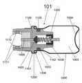
- FIGS. 1 a - 1 cillustrates an engine with a valve in a closed position in accordance with an embodiment of the instant invention.
- FIG. 1 aillustrates a cross-sectional view
- FIG. 1 billustrates a proximate end perspective view.
- FIG. 1 cillustrates a cross-sectional view with a central axis.
- FIG. 2illustrates a cross-sectional view of an engine with a valve in an open position in accordance with an embodiment of the instant invention.
- FIG. 3illustrates a cross-sectional view of an engine with a valve in accordance with an embodiment of the instant invention.
- the engine housingincludes a substantial deformation owing to it being critically overcharged.
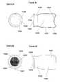
- FIGS. 4 a-dillustrate the engine housing of a needle-less injector in accordance with an embodiment of the instant invention.
- FIG. 4 ais a side perspective view
- FIG. 4 bis a side cross-sectional view
- FIG. 4 cis a proximate end perspective view
- FIG. 4 dis a distal end perspective view.
- FIGS. 5 a-cillustrate the valve body of a needle-less injector in accordance with an embodiment of the instant invention.
- FIG. 5 ais a side perspective view
- FIG. 5 bis a side cross-sectional view
- FIG. 5 cis a proximate end perspective view.
- FIGS. 6 a-cillustrate the closing ferrule of a needle-less injector in accordance with an embodiment of the instant invention, prior to the closing ferrule being mechanically fitted around a valve body and an engine housing.
- FIG. 6 ais a side perspective view
- FIG. 6 bis a side cross-sectional view
- FIG. 6 cis a proximate end perspective view.
- FIGS. 7 a-dillustrate the threaded valve stem guide of a needle-less injector in accordance with an embodiment of the instant invention.
- FIG. 7 ais a side perspective view in partial cross-section
- FIG. 7 bis a side cross-sectional view
- FIG. 7 cis a proximate end perspective view
- FIG. 7 dis a distal end perspective view.
- FIGS. 8 a-cillustrate the valve stem of a needle-less injector in accordance with an embodiment of the instant invention.
- FIG. 8 ais a side perspective view
- FIG. 8 bis a side cross-sectional view prior to the distal end being shaped
- FIG. 8 cis a proximate end perspective view.
- FIGS. 9 a-billustrate the valve spring of a needle-less injector in accordance with an embodiment of the instant invention.
- FIG. 9 ais a side perspective view in the relaxed state
- FIG. 9 bis a side perspective view in the compressed state.
- FIGS. 10 a-billustrate an engine with a valve operably interacting with another device, in accordance with an embodiment of the instant invention.
- FIG. 10 ais a side cross-sectional view of an engine with a valve in the closed position, the engine interacting with a device.
- FIG. 10 bis a side cross-sectional view of an engine with a valve in the open position, the engine interacting with a device.
- FIG. 11illustrates a side, cross-sectional view of an engine with a valve interacting with a needle-less injector, in accordance with an embodiment of the instant invention.
- the inventionis embodied in an engine with a valve.
- the enginemay include various safety and quality control features, such as a pop-out feature that indicates if the engine is critically overcharged, and a valve that may be reused.
- the reusable valveallows an engine to be used more than once, and also provides a quality control feature in that the valve may be opened and closed prior to filling the engine with compressed gas.
- the engine and valve of the present inventionmay be used with a variety of devices, including, but not limited to, a needle-less injector (FIG. 11 ).
- a central axis 1is defined through the length of a gas-pressured engine.
- This central axishas one terminus 2 at the proximate end of the engine, defined as that end of the device through which gas is expelled during normal operation of the engine.
- the other terminus 3 of the central axisis at the distal end of the engine, defined as that end of the device opposite the proximate end.
- the engine assembly 101may contain an engine housing 1000 , as depicted in FIG. 4 .
- the engine housing 1000is preferably constructed of a material impermeable to a compressed gas stored therein, and has a hollow interior chamber 1003 .
- the engine housing 1000is comprised of stainless steel or a similar metal.
- a compressed inert gasis preferably stored within the engine housing 1000 prior to use.
- the most preferred gasis carbon dioxide, though other suitable gases may be employed, as well.
- the engine assembly 101is overcharged (i.e., excess compressed gas is stored therein) to allow for use at variable altitudes without hampering its performance.
- An overcharged engine assemblymay account for, e.g., variations in altitude, whereas a critically overcharged engine assembly presents a concern of engine rupture.
- An overcharged engine, as opposed to a critically overcharged engine,is preferred in accordance with an embodiment of the instant invention, as described above.
- the engine housing 1000is preferably roughly cylindrical in shape, though alternate configurations may be utilized. Referring to FIG. 4, the engine housing 1000 may have a portion of wide diameter 1001 and a portion of small diameter 1002 , wherein the portion of small diameter 1002 is proximate to the portion of wide diameter 1001 .
- the distal end of the engine housing 1000may contain a circular depression 1004 .
- the proximate end of the engine housing 1000contains an opening 1005 , and in preferred embodiments, a closing ridge 1006 encircles the opening 1005 .
- the circular depression 1004 that may be included in the engine housing 1000 in an embodiment of the present inventionmay impart a “pop-out” safety feature to the engine.
- an overcharged engineis preferred in an embodiment of the present invention, while a critically overcharged engine may present safety concerns. Therefore, in a preferred embodiment of the present invention, as depicted in FIG. 3, the circular depression 1004 may substantially deform when the engine is critically overcharged (i.e., the internal pressure of the engine assembly is greater than a pressure threshold).
- the circular depression 1004may take on any number of geometric configurations depending on, for example, impurities latent in the material used to form the engine housing or the magnitude of the overcharging.
- the substantially inverted configuration of the circular depression illustratively depicted in FIG. 3is just one of a variety of potential configurations.
- deformed configurations of the circular depression 1004may be symmetrical or asymmetrical; may be centered about the central axis or disposed at a distance therefrom; or may include multiple deformations. Any such configuration may provide an external, visual indication that the engine is critically overcharged.
- the engine assembly 101preferably further contains a valve body 1100 , as depicted in FIG. 5 .
- the valve body 1100is preferably roughly cylindrical in its overall shape, and more preferably resides at least partially within the engine housing 1000 .
- the valve body 1100most preferably has a closing rim 1101 around its outer circumference that rests against the closing ridge 1006 encircling the opening 1005 of the proximate end of the engine housing 1000 .
- a closing ferrule 1200is wrapped around both the closing rim 1101 and closing ridge 1006 to secure the valve body 1100 and engine housing 1000 to one another (see FIG. 1 a ).
- the exterior surface of the valve body 1100 distal to the closing rim 1101is cylindrical and substantially corresponds to a preferred cylindrical interior surface of the engine housing 1000 along the portion of small diameter 1002 .
- the small diameter of the engine housing 1000is equal to or slightly greater than the diameter of the exterior surface of the valve body 1100 , thereby allowing the valve body 1100 to reside at least partially within the portion of small diameter 1002 .
- the closing ferrule 1200is shown in FIG. 6 prior to its distal portion 1201 being mechanically bent around the closing rim 1101 and closing ridge 1006 .
- the proximate portion 1202 of the closing ferrule 1200is of substantially the same diameter as the exterior of the valve body 1100 , such that bending the distal portion mechanically couples the valve body 1100 to the engine housing 1000 .
- the distal portion 1201 of the closing ferrule 1200is shown in the bent state.
- the valve body 1000preferably has a depression 1102 around its circumference adapted to fit a gasket 1103 (shown in FIG. 1 a ).
- the gasket 1103helps ensure that an airtight seal is maintained between the interior of the engine housing 1000 which contains the gas and the local atmosphere.
- the interior of the valve body 1100is preferably hollow and comprised of several distinct portions.
- the distal interior portion 1104 of the valve body 1100may contain a screw thread engagement 1105 , preferably extending from the distal end of the valve body 1100 to the distal end of a first axial cavity 1106 .
- the first axial cavity 1106may be bounded on its proximate end by a shoulder 1107 that separates this first axial cavity 1106 from a second axial cavity 1108 , which is preferably of smaller diameter than the first axial cavity 1106 .
- the shoulder 1107is an angled edge.
- at least one valve stem guide 1109protrudes from the wall of the second axial cavity 1108 . In a most preferred embodiment, there are at least three such valve stem guides 1109 that serve to substantially prevent the valve stem 1400 from moving in any direction other than along the central axis of the engine during an operation thereof
- the proximate end of a chamber 1110preferably has at least one grip 1111 extending therefrom.
- the at least one grip 1111locks around another suitable element of a needle-less injector or other device to which the engine is in operable contact, as the gripping element 1112 is situated on the interior side of the grip 1111 .
- the at least one grip 1111may lock within another element as the gripping element 1112 may be disposed on the exterior side of the grip 1111 .
- the two grips 1111are slid over and lock around a corresponding mechanical element of another device.
- the interlocking of grips 1111 with such a mechanical elementmay aid in mitigating the kickback associated with deploying the compressed gas stored in the engine assembly 101 .
- FIG. 10illustrates an engine with a valve 101 of the instant invention interacting with another device 200 (FIG. 10 a depicts the engine with a valve 101 in a closed position and FIG. 10 b depicts the engine with a valve 101 in an open position).
- the valve body 1100preferably further contains a threaded valve guide 1300 , as depicted in FIG. 7 .
- the threaded valve guide 1300is preferably cylindrical in shape and threaded around its exterior wall 1301 , such that it may be screwed into the distal interior portion 1104 of the valve body 1100 by interacting with the screw thread engagement 1105 .
- the threading on the exterior wall 1301 of the threaded valve guide 1300extends along the entirety of the exterior wall 1301 from the distal to the proximate end of the threaded valve guide 1300 .
- the threaded valve guide 1300may also contain a cylindrical interior cavity 1302 that is unobstructed at the proximate end.
- valve stem guide pane 1303The distal end, however, is preferably partially covered with a valve stem guide pane 1303 .
- the valve stem guide pane 1303preferably provides at least one vent 1304 allowing gaseous communication between the interior cavity 1302 of the threaded valve guide 1300 and the hollow interior chamber 1003 of the engine housing 1000 at the distal end of the threaded valve guide 1300 .
- the valve stem guide pane 1303includes a hole 1305 at the central axis slightly larger in diameter than the valve stem 1400 that resides therein.
- the valve stem guide pane 1303further includes a spring seat 1306 on its proximate surface that is comprised of at least one ridge 1307 that maintains the valve spring 1500 in proper position.
- the valve body 1100preferably further contains a valve stem 1400 , as depicted in FIG. 8 .
- the valve stem 1400is preferably comprised of a substantially cylindrical rod 1401 having a proximate end 1402 which is flat and a distal end 1403 which is preferably pressed or hammer-forged. The distal end 1403 is shown after hammer-forging in FIG. 8 a and prior to hammer-forged in FIG. 8 b.
- the valve body 1100may further contain a valve spring 1500 , as depicted in FIG. 9 .
- the valve spring 1500is preferably composed of wire and semi-conical in shape, wherein the proximate end 1501 is smaller in diameter than the distal end 1502 .
- the proximate end 1501 of the valve spring 1500preferably rests against the distal surface of the spring ridge 1404 on the valve stem 1400 , while the distal end 1502 of the valve spring 1500 preferably rests against the proximate surface of the valve stem guide pane 1303 and is held in place radially by the spring seat 1306 .
- valve of the instant inventionmay be repeatedly opened and closed without being destroyed (FIGS. 1 a and 2 , respectively), thus it may be inspected for quality control determinations by opening and closing at least one time prior to the engine assembly 101 being filled with compressed gas.
- the engine and valve of the present inventionmay be readily scaled up or down to any desirable proportion without significant variation from the illustrative configurations set forth herein. Such configurations may be readily ascertained without undue experimentation.
- the engine and valvemay be made to a substantially large size to function in conjunction with heavy-scale mechanical equipment.
- the engine and valvemay be made to a substantially small size to operate along with micro-scale devices.
- An uncharged engine assemblyincludes a valve, and is not filled with compressed gas.
- the uncharged engine assemblyis placed in a sealed, pressure-controlled environment, and the ambient pressure in the sealed environment is raised by the forced addition of N 2 .
- the heightened ambient pressureforces the valve of the engine into the open position, owing to the heightened pressure being relatively greater than the initial pressure within the engine housing.
- the spring included in the engineprovides a force differential that pushes the valve into the closed position.
- the ambient pressure in the sealed environmentis then lowered, and the engine is ready for use.
- the engine assemblyPrior to use, the engine assembly is checked for quality control purposes by opening and closing the valve, and thereafter the engine housing is filled with a suitable compressed gas.
- the circular depression on the engine housingis inspected to ensure no substantial deformation (i.e., the “pop-out” feature).
- the valve stemWhen the valve stem is axially depressed relative to the remainder of the engine, the valve spring is compressed and the valve opens as the valve head is separated from the shoulder residing between the first and second axial cavities of the valve body.
- Compressed gaspreviously stored in the engine housing, the interior cavity of the threaded valve guide and the first axial cavity of the valve body
- the gasrushes through the second axial cavity, past the valve stem guides, through the chamber and out the proximate end of the engine assembly.
Landscapes
- Health & Medical Sciences (AREA)
- Hematology (AREA)
- Animal Behavior & Ethology (AREA)
- Anesthesiology (AREA)
- Biomedical Technology (AREA)
- Heart & Thoracic Surgery (AREA)
- Vascular Medicine (AREA)
- Life Sciences & Earth Sciences (AREA)
- Engineering & Computer Science (AREA)
- General Health & Medical Sciences (AREA)
- Public Health (AREA)
- Veterinary Medicine (AREA)
- Lift Valve (AREA)
- Infusion, Injection, And Reservoir Apparatuses (AREA)
- Check Valves (AREA)
Abstract
Description
This is a Continuation-In-Part application of U.S. patent application Ser. No. 09/834,476 filed Apr. 13, 2001, which is incorporated by reference herein in its entirety.
This invention relates to an engine with a valve. More particularly, the invention relates to a gas-pressured engine with a valve.
Typically, needle-less medication injectors use either an expansion spring or a compressed inert gas to propel the fluid medication (via a push rod plunger) through a small orifice (an injector nozzle) which rests perpendicular to and against the injection site. The fluid medication is generally accelerated at a high rate to a speed of between about 800 feet per second (fps) and 1,200 fps (approximately 244 and 366 meters per second, respectively). This causes the fluid to pierce through the skin surface without the use of a needle, resulting in the medication being deposited in a flower pattern under the skin surface.
In a jet injector, if the inert gas is not quickly and properly expelled, fluid may be improperly injected, as with those devices employing a compression spring. Conventional disposable needle-less injectors, such as those shown in U.S. Pat. No. 4,913,699 to Parsons and U.S. Pat. No. 5,009,637 to Newman et al. utilize a gas-containing, breakable tube that is shattered or cracked open by a side mounted trigger. Difficulties arise in the need to maintain tight tolerances on the breakable member, since minor changes in thickness can dramatically effect the pressure needed to deploy the gas from the gas chamber of the device. In addition, the broken shards of the breakable member are ejected at high speed when the gas is expelled and these shards can occasionally jam between the plunger driver and the housing, thereby preventing proper operation of the needle-less injector. Attempts to prevent small shards from being formed would obviate some of this potential, but tend to make activation of the device more difficult.
U.S. Pat. Nos. 6,080,130, 6,063,053, 5,851,198 and 5,730,723 describe needle-less injectors incorporating a gas power source, thus obviating some of the limitations inherent in compression spring injectors and addressing many of the concerns of conventional jet injectors. The injectors described therein have a pre-filled and self-contained compressed gas for providing pressure to inject medication into the skin surface of a patient without the use of a needle.
Gas power sources for needle-less injectors that employ either pop valves or breakaway tab valves to release the inert gas stored in their respective gas chambers, however, may only be opened once, thereby presenting difficulty with regard to quality control testing measures. Additionally, in filling a gas power source with compressed gas, safety measures and a range of quality control features are important. For instance, if a gas power source is critically overcharged, it may rupture during or after filling with a compressed gas. A rupture may occur in storage or even during operation (e.g., during the administration of a needle-less injection). Such an event may result in substantial injury to the recipient of an injection or to an individual administering the same. Other undesirable results may occur when the engine is used in conjunction with a device other than a needle-less injector, including harm to an individual or damage to a device to which such an engine is in operable contact.
It is therefore an object of an embodiment of the instant invention to provide a gas-pressured engine that obviates, for practical purposes, the above-mentioned limitations.
In one embodiment of the instant invention, an engine includes an engine housing and a valve. Compressed gas may be contained in the engine housing, and released upon an opening of the valve. Further, the engine housing may include a depression on one end; the depression imparting to the engine a “pop-out” safety feature, wherein, when the engine is critically overcharged, the depression may substantially invert or otherwise deform its shape to provide greater internal volume for the compressed gas. This feature may avoid an engine rupture and may also provide an external visual cue that the engine is critically overcharged.
In another embodiment of the present invention, an engine is fitted with a reusable valve. The valve may contain a rubber head that is held against a fixed element of the engine such that depression of a trigger separates the head from the fixed element, releasing the compressed gas from the engine. A spring may be included in the valve to help maintain a proper airtight seal with the canister holding the compressed gas.
FIGS. 1a-1cillustrates an engine with a valve in a closed position in accordance with an embodiment of the instant invention.
FIG. 1aillustrates a cross-sectional view.
FIG. 1billustrates a proximate end perspective view.
FIG. 1cillustrates a cross-sectional view with a central axis.
FIG. 2 illustrates a cross-sectional view of an engine with a valve in an open position in accordance with an embodiment of the instant invention.
FIG. 3 illustrates a cross-sectional view of an engine with a valve in accordance with an embodiment of the instant invention. The engine housing includes a substantial deformation owing to it being critically overcharged.
FIGS. 4a-dillustrate the engine housing of a needle-less injector in accordance with an embodiment of the instant invention.
FIG. 4ais a side perspective view,
FIG. 4bis a side cross-sectional view,
FIG. 4cis a proximate end perspective view and
FIG. 4dis a distal end perspective view.
FIGS. 5a-cillustrate the valve body of a needle-less injector in accordance with an embodiment of the instant invention.
FIG. 5ais a side perspective view,
FIG. 5bis a side cross-sectional view and
FIG. 5cis a proximate end perspective view.
FIGS. 6a-cillustrate the closing ferrule of a needle-less injector in accordance with an embodiment of the instant invention, prior to the closing ferrule being mechanically fitted around a valve body and an engine housing.
FIG. 6ais a side perspective view,
FIG. 6bis a side cross-sectional view and
FIG. 6cis a proximate end perspective view.
FIGS. 7a-dillustrate the threaded valve stem guide of a needle-less injector in accordance with an embodiment of the instant invention.
FIG. 7ais a side perspective view in partial cross-section,
FIG. 7bis a side cross-sectional view,
FIG. 7cis a proximate end perspective view and
FIG. 7dis a distal end perspective view.
FIGS. 8a-cillustrate the valve stem of a needle-less injector in accordance with an embodiment of the instant invention.
FIG. 8ais a side perspective view,
FIG. 8bis a side cross-sectional view prior to the distal end being shaped and
FIG. 8cis a proximate end perspective view.
FIGS. 9a-billustrate the valve spring of a needle-less injector in accordance with an embodiment of the instant invention.
FIG. 9ais a side perspective view in the relaxed state,
FIG. 9bis a side perspective view in the compressed state.
FIGS. 10a-billustrate an engine with a valve operably interacting with another device, in accordance with an embodiment of the instant invention.
FIG. 10ais a side cross-sectional view of an engine with a valve in the closed position, the engine interacting with a device.
FIG. 10bis a side cross-sectional view of an engine with a valve in the open position, the engine interacting with a device.
FIG. 11 illustrates a side, cross-sectional view of an engine with a valve interacting with a needle-less injector, in accordance with an embodiment of the instant invention.
As shown in the drawings for purposes of illustration, the invention is embodied in an engine with a valve. The engine may include various safety and quality control features, such as a pop-out feature that indicates if the engine is critically overcharged, and a valve that may be reused. The reusable valve allows an engine to be used more than once, and also provides a quality control feature in that the valve may be opened and closed prior to filling the engine with compressed gas. The engine and valve of the present invention may be used with a variety of devices, including, but not limited to, a needle-less injector (FIG.11).
For ease in describing the various elements of the instant invention, the following spatial coordinate system will apply thereto. As depicted in FIG. 1c,a central axis1 is defined through the length of a gas-pressured engine. This central axis has one terminus2 at the proximate end of the engine, defined as that end of the device through which gas is expelled during normal operation of the engine. The other terminus3 of the central axis is at the distal end of the engine, defined as that end of the device opposite the proximate end. Thus, various elements of the device of the instant invention may be described with reference to their respective proximate and distal portions, as well as their central axes.
Anengine assembly 101 is provided in an embodiment of the present invention, as depicted in FIG. 1a.Theengine assembly 101 may contain anengine housing 1000, as depicted in FIG.4. Theengine housing 1000 is preferably constructed of a material impermeable to a compressed gas stored therein, and has a hollowinterior chamber 1003. Most preferably, theengine housing 1000 is comprised of stainless steel or a similar metal. A compressed inert gas is preferably stored within theengine housing 1000 prior to use. The most preferred gas is carbon dioxide, though other suitable gases may be employed, as well. In most preferred embodiments, theengine assembly 101 is overcharged (i.e., excess compressed gas is stored therein) to allow for use at variable altitudes without hampering its performance. This is to be distinguished from the instance in which the engine assembly is critically overcharged, which is the instance wherein the pressure inside the engine assembly is higher than a pressure threshold. An overcharged engine assembly may account for, e.g., variations in altitude, whereas a critically overcharged engine assembly presents a concern of engine rupture. An overcharged engine, as opposed to a critically overcharged engine, is preferred in accordance with an embodiment of the instant invention, as described above.
Theengine housing 1000 is preferably roughly cylindrical in shape, though alternate configurations may be utilized. Referring to FIG. 4, theengine housing 1000 may have a portion ofwide diameter 1001 and a portion ofsmall diameter 1002, wherein the portion ofsmall diameter 1002 is proximate to the portion ofwide diameter 1001. The distal end of theengine housing 1000 may contain acircular depression 1004. The proximate end of theengine housing 1000 contains anopening 1005, and in preferred embodiments, aclosing ridge 1006 encircles theopening 1005.
Thecircular depression 1004 that may be included in theengine housing 1000 in an embodiment of the present invention may impart a “pop-out” safety feature to the engine. As noted above, an overcharged engine is preferred in an embodiment of the present invention, while a critically overcharged engine may present safety concerns. Therefore, in a preferred embodiment of the present invention, as depicted in FIG. 3, thecircular depression 1004 may substantially deform when the engine is critically overcharged (i.e., the internal pressure of the engine assembly is greater than a pressure threshold).
In a deformed state, thecircular depression 1004 may take on any number of geometric configurations depending on, for example, impurities latent in the material used to form the engine housing or the magnitude of the overcharging. Thus, the substantially inverted configuration of the circular depression illustratively depicted in FIG. 3 is just one of a variety of potential configurations. By way of example, deformed configurations of thecircular depression 1004 may be symmetrical or asymmetrical; may be centered about the central axis or disposed at a distance therefrom; or may include multiple deformations. Any such configuration may provide an external, visual indication that the engine is critically overcharged.
Theengine assembly 101 preferably further contains avalve body 1100, as depicted in FIG.5. Thevalve body 1100 is preferably roughly cylindrical in its overall shape, and more preferably resides at least partially within theengine housing 1000. Thevalve body 1100 most preferably has aclosing rim 1101 around its outer circumference that rests against theclosing ridge 1006 encircling theopening 1005 of the proximate end of theengine housing 1000. Most preferably, aclosing ferrule 1200 is wrapped around both theclosing rim 1101 andclosing ridge 1006 to secure thevalve body 1100 andengine housing 1000 to one another (see FIG. 1a).
In a most preferred embodiment of the present invention, as depicted in FIG. 1a,the exterior surface of thevalve body 1100 distal to theclosing rim 1101 is cylindrical and substantially corresponds to a preferred cylindrical interior surface of theengine housing 1000 along the portion ofsmall diameter 1002. Most preferably, the small diameter of theengine housing 1000 is equal to or slightly greater than the diameter of the exterior surface of thevalve body 1100, thereby allowing thevalve body 1100 to reside at least partially within the portion ofsmall diameter 1002.
Theclosing ferrule 1200 is shown in FIG. 6 prior to itsdistal portion 1201 being mechanically bent around theclosing rim 1101 andclosing ridge 1006. Theproximate portion 1202 of theclosing ferrule 1200 is of substantially the same diameter as the exterior of thevalve body 1100, such that bending the distal portion mechanically couples thevalve body 1100 to theengine housing 1000. In FIG. 1b,thedistal portion 1201 of theclosing ferrule 1200 is shown in the bent state. Thevalve body 1000 preferably has adepression 1102 around its circumference adapted to fit a gasket1103 (shown in FIG. 1a). Thegasket 1103 helps ensure that an airtight seal is maintained between the interior of theengine housing 1000 which contains the gas and the local atmosphere.
Referring to FIG. 5, the interior of thevalve body 1100 is preferably hollow and comprised of several distinct portions. The distalinterior portion 1104 of thevalve body 1100 may contain ascrew thread engagement 1105, preferably extending from the distal end of thevalve body 1100 to the distal end of a firstaxial cavity 1106. The firstaxial cavity 1106 may be bounded on its proximate end by ashoulder 1107 that separates this firstaxial cavity 1106 from a secondaxial cavity 1108, which is preferably of smaller diameter than the firstaxial cavity 1106. In preferred embodiments, theshoulder 1107 is an angled edge. Also in preferred embodiments, at least onevalve stem guide 1109 protrudes from the wall of the secondaxial cavity 1108. In a most preferred embodiment, there are at least three such valve stem guides1109 that serve to substantially prevent thevalve stem 1400 from moving in any direction other than along the central axis of the engine during an operation thereof
In one embodiment of the present invention, the proximate end of achamber 1110 preferably has at least onegrip 1111 extending therefrom. Preferably, the at least onegrip 1111 locks around another suitable element of a needle-less injector or other device to which the engine is in operable contact, as thegripping element 1112 is situated on the interior side of thegrip 1111. In alternative embodiments, however, the at least onegrip 1111 may lock within another element as thegripping element 1112 may be disposed on the exterior side of thegrip 1111. In most preferred embodiments, there are twogrips 1111 disposed opposite one another each of which contains agripping element 1112 situated on the interior side of thegrip 1111. In these most preferred embodiments, the twogrips 1111 are slid over and lock around a corresponding mechanical element of another device. The interlocking ofgrips 1111 with such a mechanical element may aid in mitigating the kickback associated with deploying the compressed gas stored in theengine assembly 101. An example of this feature is illustratively depicted in FIG. 10 which illustrates an engine with avalve 101 of the instant invention interacting with another device200 (FIG. 10adepicts the engine with avalve 101 in a closed position and FIG. 10bdepicts the engine with avalve 101 in an open position).
Thevalve body 1100 preferably further contains a threadedvalve guide 1300, as depicted in FIG.7. The threadedvalve guide 1300 is preferably cylindrical in shape and threaded around itsexterior wall 1301, such that it may be screwed into the distalinterior portion 1104 of thevalve body 1100 by interacting with thescrew thread engagement 1105. Most preferably, the threading on theexterior wall 1301 of the threadedvalve guide 1300 extends along the entirety of theexterior wall 1301 from the distal to the proximate end of the threadedvalve guide 1300. The threadedvalve guide 1300 may also contain a cylindricalinterior cavity 1302 that is unobstructed at the proximate end. The distal end, however, is preferably partially covered with a valvestem guide pane 1303. The valve stemguide pane 1303 preferably provides at least onevent 1304 allowing gaseous communication between theinterior cavity 1302 of the threadedvalve guide 1300 and the hollowinterior chamber 1003 of theengine housing 1000 at the distal end of the threadedvalve guide 1300. Also preferably, the valvestem guide pane 1303 includes ahole 1305 at the central axis slightly larger in diameter than thevalve stem 1400 that resides therein. Most preferably, the valvestem guide pane 1303 further includes aspring seat 1306 on its proximate surface that is comprised of at least oneridge 1307 that maintains thevalve spring 1500 in proper position.
Thevalve body 1100 preferably further contains avalve stem 1400, as depicted in FIG.8. Thevalve stem 1400 is preferably comprised of a substantiallycylindrical rod 1401 having aproximate end 1402 which is flat and adistal end 1403 which is preferably pressed or hammer-forged. Thedistal end 1403 is shown after hammer-forging in FIG. 8aand prior to hammer-forged in FIG. 8b.Most preferably, there is also included aspring ridge 1404 that extends radially from therod 1401, and a roughlyconical valve head 1405 affixed to the proximate and exterior surfaces of thespring ridge 1404 as well as that portion of therod 1401 immediately proximate to thespring ridge 1404. Most preferably, thevalve head 1405 is comprised of a rubber material such as semi-permeable, silicon-based or butyl-based rubber that is sufficiently malleable for use in accordance with the engine. In most preferred embodiments, the angle between the proximate surface of thevalve head 1405 and the central axis is substantially similar to the angle of theshoulder 1107 located between the firstaxial cavity 1106 and secondaxial cavity 1108 of thevalve body 1100.
Thevalve body 1100 may further contain avalve spring 1500, as depicted in FIG.9. Thevalve spring 1500 is preferably composed of wire and semi-conical in shape, wherein theproximate end 1501 is smaller in diameter than thedistal end 1502. Theproximate end 1501 of thevalve spring 1500 preferably rests against the distal surface of thespring ridge 1404 on thevalve stem 1400, while thedistal end 1502 of thevalve spring 1500 preferably rests against the proximate surface of the valvestem guide pane 1303 and is held in place radially by thespring seat 1306.
Furthermore, the valve of the instant invention may be repeatedly opened and closed without being destroyed (FIGS. 1aand2, respectively), thus it may be inspected for quality control determinations by opening and closing at least one time prior to theengine assembly 101 being filled with compressed gas.
Moreover, the engine and valve of the present invention may be readily scaled up or down to any desirable proportion without significant variation from the illustrative configurations set forth herein. Such configurations may be readily ascertained without undue experimentation. For instance, the engine and valve may be made to a substantially large size to function in conjunction with heavy-scale mechanical equipment. Alternatively, the engine and valve may be made to a substantially small size to operate along with micro-scale devices.
An uncharged engine assembly includes a valve, and is not filled with compressed gas. The uncharged engine assembly is placed in a sealed, pressure-controlled environment, and the ambient pressure in the sealed environment is raised by the forced addition of N2. The heightened ambient pressure forces the valve of the engine into the open position, owing to the heightened pressure being relatively greater than the initial pressure within the engine housing. After the ambient pressure and pressure within the engine housing equilibrate (i.e., the pressure in the environment is substantially equal to the pressure within the engine assembly), the spring included in the engine provides a force differential that pushes the valve into the closed position. The ambient pressure in the sealed environment is then lowered, and the engine is ready for use.
Prior to use, the engine assembly is checked for quality control purposes by opening and closing the valve, and thereafter the engine housing is filled with a suitable compressed gas. The circular depression on the engine housing is inspected to ensure no substantial deformation (i.e., the “pop-out” feature). When the valve stem is axially depressed relative to the remainder of the engine, the valve spring is compressed and the valve opens as the valve head is separated from the shoulder residing between the first and second axial cavities of the valve body. Compressed gas (previously stored in the engine housing, the interior cavity of the threaded valve guide and the first axial cavity of the valve body) may then rush through the gap created between the valve head and the shoulder. The gas rushes through the second axial cavity, past the valve stem guides, through the chamber and out the proximate end of the engine assembly.
While the description above refers to particular embodiments of the present invention, it should be readily apparent to people of ordinary skill in the art that a number of modifications may be made without departing from the spirit thereof The accompanying claims are intended to cover such modifications as would fall within the true spirit and scope of the invention. The presently disclosed embodiments are, therefore, to be considered in all respects as illustrative and not restrictive, the scope of the invention being indicated by the appended claims rather than the foregoing description. All changes that come within the meaning of and range of equivalency of the claims are intended to be embraced therein.
Claims (79)
1. An engine comprising:
an engine housing to contain a compressed gas, said engine housing including an engine housing opening; and
a valve traversing said engine housing opening, said valve including:
a valve opening;
a valve stem;
a valve head configured to obstruct the passage of a compressed gas through said valve opening when said valve is in a closed position, said valve head being affixed to said valve stem;
a valve guide to maintain said valve stem in proper alignment with said valve opening, said valve guide further including a valve stem guide pane with a hole configured therein, said valve stem guide pane being configured perpendicularly to said valve stem, and said valve stem being slidably disposed within said hole; and
a spring disposed between said valve head at a first spring end and said valve stem guide pane at a second spring end, said valve stem being slidably disposed within said spring.
2. The engine ofclaim 1 , wherein said engine housing further includes a first portion terminating at one end at said engine housing opening.
3. The engine ofclaim 2 , wherein said valve further includes an exterior valve surface.
4. The engine ofclaim 3 , wherein said exterior valve surface resides within said first portion of said engine housing.
5. The engine ofclaim 4 , said engine further including a gasket configured between said exterior valve surface and said first portion of said engine housing.
6. The engine ofclaim 5 , wherein said exterior valve surface further includes a circumferential depression, and said gasket is disposed within said circumferential depression.
7. The engine ofclaim 3 , wherein said first portion of said engine housing and said exterior valve surface are substantially cylindrical.
8. The engine ofclaim 3 , wherein said valve further includes a closing rim disposed circumferentially about an exterior of said valve, and said exterior valve surface terminates at one end at said closing rim.
9. The engine ofclaim 8 , wherein said engine housing further includes a closing ridge disposed circumferentially about said engine housing opening.
10. The engine ofclaim 9 , said engine further including a closing ferrule to operably engage said closing rim and said closing ridge, and to maintain said closing rim and said closing ridge in a fixed position relative to one another.
11. The engine ofclaim 2 , wherein said engine housing further includes a second portion configured between said first portion and an end of said engine housing.
12. The engine ofclaim 11 , wherein said end of said engine housing further includes a depression to substantially deform when an internal pressure of said engine housing surpasses a pressure threshold.
13. The engine ofclaim 1 , wherein said valve stem further includes an exterior valve stem portion that resides exterior to said valve opening.
14. The engine ofclaim 13 , wherein said valve opens upon an application of a force to said exterior valve stem portion, wherein at least a component of said force is directed along a longitudinal axis of said valve stem.
15. The engine ofclaim 1 , wherein said valve further includes an axial cavity partially defined by an interior surface of said valve.
16. The engine ofclaim 15 , wherein said valve further includes at least one valve stem guide protruding from said axial cavity to substantially prevent said valve stem from moving in any direction other than transverse to said valve opening.
17. The engine ofclaim 16 , wherein said valve further includes three valve stem guides, said three valve stem guides being disposed equidistant from one another about said axial cavity.
18. The engine ofclaim 15 , wherein said axial cavity terminates at one end at said valve opening and at an opposing end at a shoulder, said shoulder being configured to contact said valve head when said valve is in said closed position.
19. The engine ofclaim 18 , wherein said shoulder and said valve head are configured to contact one another in a manner that provides a substantially airtight seal therebetween.
20. The engine ofclaim 19 , wherein said valve head is comprised of a material selected from the group consisting of silicon-based rubber and butyl-based rubber.
21. The engine ofclaim 15 , wherein said valve further includes an additional axial cavity configured between said axial cavity and a valve guide end of said valve.
22. The engine ofclaim 21 , wherein said valve further includes a segment of interior screw threading configured between said additional axial cavity and said valve guide end of said valve.
23. The engine ofclaim 22 , wherein said valve guide further includes a segment of exterior screw threading to operably interact with said interior screw threading to attach said valve guide to said valve.
24. The engine ofclaim 1 , wherein said valve further includes at least one vent configured between said valve stem guide pane and said valve guide to provide gaseous communication between said engine housing and an exterior of said engine.
25. The engine ofclaim 24 , wherein said valve stem further includes a ridge configured circumferentially about said valve stem, said valve head being affixed to said ridge.
26. The engine ofclaim 1 , wherein said first spring end includes a smaller diameter than said second spring end.
27. The engine ofclaim 1 , wherein said valve stem further includes a pressed or hammer-forged end configured on an opposite side of said valve stem guide pane from said valve head.
28. The engine ofclaim 1 , wherein said valve is capable of being repeatedly opened.
29. The engine ofclaim 1 , wherein said valve further includes at least one grip to engage a device with which said engine operates, said at least one grip extending from that end of said valve through which a compressed gas is capable of escaping when said valve is in an open position, said at least one grip further including a gripping element adapted to lockingly engage with said device.
30. The engine ofclaim 1 , wherein said engine is used in conjunction with a needle-less injector.
31. An engine comprising:
an engine housing to contain a compressed gas, said engine housing including an engine housing opening; and
a valve traversing said engine housing opening, said valve including:
a valve opening;
a valve stem;
a valve head to obstruct the passage of a compressed gas through said valve opening when said valve is in a closed position, said valve head being affixed to said valve stem;
a valve guide to maintain said valve stem in proper alignment with said valve opening; and
at least one grip adapted to engage a device with which said engine operates, said at least one grip extending from that end of said valve through which a compressed gas is capable of escaping when said valve is in an open position, said at least one grip further including a gripping element adapted to lockingly engage with said device.
32. The engine ofclaim 31 , wherein said engine housing further includes a first portion terminating at one end at said engine housing opening.
33. The engine ofclaim 32 , wherein said valve further includes an exterior valve surface.
34. The engine ofclaim 33 , wherein said exterior valve surface resides within said first portion of said engine housing.
35. The engine ofclaim 34 , wherein said engine further including a gasket configured between said exterior valve surface and said first portion of said engine housing.
36. The engine ofclaim 35 , wherein said exterior valve surface further includes a circumferential depression, and said gasket is disposed within said circumferential depression.
37. The engine ofclaim 33 , wherein said first portion of said engine housing and said exterior valve surface are substantially cylindrical.
38. The engine ofclaim 33 , wherein said valve further includes a closing rim disposed circumferentially about an exterior of said valve, and said exterior valve surface terminates at one end at said closing rim.
39. The engine ofclaim 38 , wherein said engine housing further includes a closing ridge disposed circumferentially about said engine housing opening.
40. The engine ofclaim 39 , said engine further including a closing ferrule to operably engage said closing rim and said closing ridge, and to maintain said closing rim and said closing ridge in a fixed position relative to one another.
41. The engine ofclaim 32 , wherein said engine housing further includes a second portion configured between said first portion and an end of said engine housing.
42. The engine ofclaim 41 , wherein said end of said engine housing further includes a depression to substantially deform when an internal pressure of said engine housing surpasses a pressure threshold.
43. The engine ofclaim 31 , wherein said valve stem further includes an exterior valve stem portion that resides exterior to said valve opening.
44. The engine ofclaim 43 , wherein said valve opens upon an application of a force to said exterior valve stem portion, wherein at least a component of said force is directed along a longitudinal axis of said valve stem.
45. The engine ofclaim 31 , wherein said valve further includes an axial cavity partially defined by an interior surface of said valve.
46. The engine ofclaim 45 , wherein said valve further includes at least one valve stem guide protruding from said axial cavity to substantially prevent said valve stem from moving in any direction other than transverse to said valve opening.
47. The engine ofclaim 46 , wherein said valve further includes three valve stem guides, said three valve stem guides being disposed equidistant from one another about said axial cavity.
48. The engine ofclaim 45 , wherein said axial cavity terminates at one end at said valve opening and at an opposing end at a shoulder, said shoulder being configured to contact said valve head when said valve is in said closed position.
49. The engine ofclaim 48 , wherein said shoulder and said valve head are configured to contact one another in a manner that provides a substantially airtight seal therebetween.
50. The engine ofclaim 49 , wherein said valve head is comprised of a material selected from the group consisting of silicon-based rubber and butyl-based rubber.
51. The engine ofclaim 45 , wherein said valve further includes an additional axial cavity configured between said axial cavity and a valve guide end of said valve.
52. The engine ofclaim 51 , wherein said valve further includes a segment of interior screw threading configured between said additional axial cavity and said valve guide end of said valve.
53. The engine ofclaim 52 , wherein said valve guide further includes a segment of exterior screw threading to operably interact with said interior screw threading to attach said valve guide to said valve.
54. The engine ofclaim 31 , wherein said valve guide further includes a valve stem guide pane with a hole configured therein, said valve stem guide pane being configured perpendicularly to said valve stem, and said valve stem being slidably disposed within said hole.
55. The engine ofclaim 54 , wherein said valve further includes at least one vent configured between said valve stem guide pane and said valve guide to provide gaseous communication between said engine housing and an exterior of said engine.
56. The engine ofclaim 55 , wherein said valve stem further includes a ridge configured circumferentially about said valve stem, said valve head being affixed to said ridge.
57. The engine ofclaim 56 , wherein said valve further includes a spring disposed between said ridge at a first spring end and said valve stem guide pane at a second spring end.
58. The engine ofclaim 57 , wherein said first spring end includes a smaller diameter than said second spring end.
59. The engine ofclaim 54 , wherein said valve stem further includes a flattened end configured on an opposite side of said valve stem guide pane from said valve head.
60. The engine ofclaim 31 , wherein said valve is capable of being repeatedly opened.
61. The engine ofclaim 31 , wherein said engine is used in conjunction with a needle-less injector.
62. A method for determining whether an engine housing is critically overcharged comprising:
providing an engine housing including:
a first end that further includes a depression capable of substantially deforming when an internal pressure of said engine housing surpasses a pressure threshold, and
a second end operably coupled to a valve, said valve including:
a valve opening,
a valve stem,
a valve head configured to obstruct the passage of a compressed gas through said valve opening when said valve is in a closed position, said valve head being affixed to said valve stem,
a valve guide to maintain said valve stem in alignment with said valve opening, said valve guide further including a valve stem guide pane with a hole configured therein, said valve stem guide pane being configured perpendicularly to said valve stem, and said valve stem being slidably disposed within said hole, and
a spring disposed between said valve head at a first spring end and said valve stem guide pane at a second spring end, said valve stem being slidably disposed within said spring;
filling said engine housing with a compressed gas;
inspecting said depression for a substantial deformation; and
determining that said engine housing is critically overcharged if a substantial deformation is found on said first end.
63. The method ofclaim 62 , wherein said engine housing is used in conjunction with a needle-less injector.
64. The method ofclaim 62 , said method being implemented as at least a part of a manufacturing quality control scheme.
65. A method of filling an engine with a compressed gas comprising:
providing an engine including:
an engine housing to contain a compressed gas, said engine housing including an engine housing opening, and
a valve traversing said engine housing opening, said valve including:
a valve opening,
a valve stem,
a valve head configured to obstruct the passage of a compressed gas through said valve opening when said valve is in a closed position, said valve head being affixed to said valve stem,
a valve guide to maintain said valve stem in alignment with said valve opening, said valve guide further including a valve stem guide pane with a hole configured therein, said valve stem guide pane being configured perpendicularly to said valve stem, and said valve stem being slidably disposed within said hole, and
a spring disposed between said valve head at a first spring end and said valve stem guide pane at a second spring end, said valve stem being slidably disposed within said spring;
placing said engine within a pressure-controlled environment;
raising a pressure level in said pressure-controlled environment to a raised pressure level; and
allowing a pressure within said engine to equilibrate with said raised pressure level.
66. The method ofclaim 65 , wherein said valve further includes a spring to push said valve into a closed position once said pressure within said engine equilibrates with said raised pressure level.
67. The method ofclaim 65 , wherein raising a pressure level includes forcing a gas into said pressure-controlled environment.
68. The method ofclaim 67 , wherein said gas is selected from the group consisting of air, carbon dioxide (CO2), nitrogen (N2) and inert gases.
69. The method ofclaim 65 , wherein allowing a pressure within said engine to equilibrate with said raised pressure level further includes waiting for said valve to move into a closed position.
70. The method ofclaim 65 , further including using said engine in conjunction with a needle-less injector.
71. A method for determining whether an engine housing is critically overcharged comprising:
providing an engine housing including:
a first end that further includes a depression capable of substantially deforming when an internal pressure of said engine housing surpasses a pressure threshold, and
a second end operably coupled to a valve, said valve including:
a valve opening,
a valve stem,
a valve head to obstruct the passage of a compressed gas through said valve opening when said valve is in a closed position, said valve head being affixed to said valve stem,
a valve guide to maintain said valve stem in alignment with said valve opening, and
at least one grip adapted to engage a device with which said engine operates, said at least one grip extending from that end of said valve through which a gas is capable of escaping when said
valve is in an open position, said at least one grip further including
a gripping element adapted to lockingly engage with said device;
filling said engine housing with a compressed gas;
inspecting said depression for a substantial deformation; and
determining that said engine housing is critically overcharged if a substantial deformation is found on said first end.
72. The method ofclaim 71 , wherein said engine housing is used in conjunction with a needle-less injector.
73. The method ofclaim 71 , said method being implemented as at least a part of a manufacturing quality control scheme.
74. A method of filling an engine with a compressed gas comprising:
providing an engine including:
an engine housing to contain a compressed gas, said engine housing including an engine housing opening, and
a valve traversing said engine housing opening, said valve including:
a valve opening,
a valve stem,
a valve head to obstruct the passage of a compressed gas through said valve opening when said valve is in a closed position, said valve head being affixed to said valve stem,
a valve guide to maintain said valve stem in alignment with said valve opening, and
at least one grip adapted to engage a device with which said engine operates, said at least one grip extending from that end of said valve through which a gas is capable of escaping when said valve is in an open position, said at least one grip further including a gripping element adapted to lockingly engage with said device;
placing said engine within a pressure-controlled environment;
raising a pressure level in said pressure-controlled environment to a raised pressure level; and
allowing a pressure within said engine to equilibrate with said raised pressure level.
75. The method ofclaim 74 , wherein said valve further includes a spring to push said valve into a closed position once said pressure within said engine equilibrates with said raised pressure level.
76. The method ofclaim 74 , wherein raising a pressure level includes forcing a gas into said pressure-controlled environment.
77. The method ofclaim 76 , wherein said gas is selected from the group consisting of air, carbon dioxide (CO2), nitrogen (N2) and inert gases.
78. The method ofclaim 74 , wherein allowing a pressure within said engine to equilibrate with said raised pressure level further includes waiting for said valve to move into a closed position.
79. The method ofclaim 74 , further including using said engine in conjunction with a needle-less injector.
Priority Applications (1)
| Application Number | Priority Date | Filing Date | Title |
|---|---|---|---|
| US10/099,846US6613011B2 (en) | 2001-04-13 | 2002-03-15 | Gas-pressured engine with valve |
Applications Claiming Priority (2)
| Application Number | Priority Date | Filing Date | Title |
|---|---|---|---|
| US09/834,476US6613010B2 (en) | 2001-04-13 | 2001-04-13 | Modular gas-pressured needle-less injector |
| US10/099,846US6613011B2 (en) | 2001-04-13 | 2002-03-15 | Gas-pressured engine with valve |
Related Parent Applications (1)
| Application Number | Title | Priority Date | Filing Date |
|---|---|---|---|
| US09/834,476Continuation-In-PartUS6613010B2 (en) | 2001-04-13 | 2001-04-13 | Modular gas-pressured needle-less injector |
Publications (2)
| Publication Number | Publication Date |
|---|---|
| US20020151841A1 US20020151841A1 (en) | 2002-10-17 |
| US6613011B2true US6613011B2 (en) | 2003-09-02 |
Family
ID=25267028
Family Applications (3)
| Application Number | Title | Priority Date | Filing Date |
|---|---|---|---|
| US09/834,476Expired - Fee RelatedUS6613010B2 (en) | 2001-04-13 | 2001-04-13 | Modular gas-pressured needle-less injector |
| US10/099,846Expired - Fee RelatedUS6613011B2 (en) | 2001-04-13 | 2002-03-15 | Gas-pressured engine with valve |
| US10/227,879AbandonedUS20030083612A1 (en) | 2001-04-13 | 2002-08-26 | Apparatus for needle-less injection with a degassed fluid |
Family Applications Before (1)
| Application Number | Title | Priority Date | Filing Date |
|---|---|---|---|
| US09/834,476Expired - Fee RelatedUS6613010B2 (en) | 2001-04-13 | 2001-04-13 | Modular gas-pressured needle-less injector |
Family Applications After (1)
| Application Number | Title | Priority Date | Filing Date |
|---|---|---|---|
| US10/227,879AbandonedUS20030083612A1 (en) | 2001-04-13 | 2002-08-26 | Apparatus for needle-less injection with a degassed fluid |
Country Status (3)
| Country | Link |
|---|---|
| US (3) | US6613010B2 (en) |
| AU (1) | AU2002244302A1 (en) |
| WO (1) | WO2002083197A2 (en) |
Cited By (15)
| Publication number | Priority date | Publication date | Assignee | Title |
|---|---|---|---|---|
| US20040206926A1 (en)* | 2003-04-21 | 2004-10-21 | Smith Michael C. | Alignment device for valve bonnet |
| US20090277970A1 (en)* | 2006-06-26 | 2009-11-12 | Battelle Memorial Institute | Cartridge having self-actuating seal for a wetted lead screw |
| US20100116897A1 (en)* | 2006-06-26 | 2010-05-13 | Battelle Memorial Institute | Handheld sprayer with removable cartridge and method of using same |
| US20100305624A1 (en)* | 2009-05-26 | 2010-12-02 | Zimmer, Inc. | Bone fixation tool |
| US8221347B2 (en) | 2004-12-01 | 2012-07-17 | Acushot, Inc. | Needle-free injector |
| US9987067B2 (en) | 2012-07-11 | 2018-06-05 | Zimmer, Inc. | Bone fixation tool |
| US10179017B2 (en) | 2014-04-03 | 2019-01-15 | Zimmer, Inc. | Orthopedic tool for bone fixation |
| US10918791B2 (en)* | 2005-02-01 | 2021-02-16 | Kaleo, Inc. | Devices, systems and methods for medicament delivery |
| US10966704B2 (en) | 2016-11-09 | 2021-04-06 | Biomet Sports Medicine, Llc | Methods and systems for stitching soft tissue to bone |
| US11167087B2 (en) | 2019-08-09 | 2021-11-09 | Kaleo, Inc. | Devices and methods for delivery of substances within a prefilled syringe |
| US11426520B2 (en) | 2011-01-26 | 2022-08-30 | Kaleo, Inc. | Medicament delivery devices for administration of a medicament within a prefilled syringe |
| US11517674B2 (en) | 2015-06-30 | 2022-12-06 | Kaleo, Inc. | Auto-injectors for administration of a medicament within a prefilled syringe |
| US11590286B2 (en) | 2004-11-22 | 2023-02-28 | Kaleo, Inc. | Devices, systems and methods for medicament delivery |
| US12005236B2 (en) | 2015-03-24 | 2024-06-11 | Kaleo, Inc. | Devices and methods for delivering a lyophilized medicament |
| US12268847B1 (en) | 2021-02-10 | 2025-04-08 | Kaleo, Inc. | Devices and methods for delivery of substances within a medicament container |
Families Citing this family (33)
| Publication number | Priority date | Publication date | Assignee | Title |
|---|---|---|---|---|
| US6824526B2 (en)* | 2001-10-22 | 2004-11-30 | Penjet Corporation | Engine and diffuser for use with a needle-less injector |
| GB0125506D0 (en) | 2001-10-24 | 2001-12-12 | Weston Medical Ltd | Needle free injection method and apparatus |
| GB0206560D0 (en)* | 2002-03-20 | 2002-05-01 | Glaxo Group Ltd | Novel device |
| GB0217802D0 (en)* | 2002-08-01 | 2002-09-11 | Glaxo Group Ltd | A fluid dispensing device |
| DE10340586A1 (en)* | 2003-09-03 | 2005-04-07 | Tecpharma Licensing Ag | Mixing device for multi-chamber ampoule |
| EP1689465A4 (en)* | 2003-12-05 | 2011-10-12 | Zogenix Inc | A device for readying a needle free injector for delivery |
| WO2006057636A1 (en) | 2004-11-22 | 2006-06-01 | Intelliject, Llc | Devices, systems, and methods for medicament delivery |
| US7648483B2 (en) | 2004-11-22 | 2010-01-19 | Intelliject, Inc. | Devices, systems and methods for medicament delivery |
| US10737028B2 (en) | 2004-11-22 | 2020-08-11 | Kaleo, Inc. | Devices, systems and methods for medicament delivery |
| US8591457B2 (en) | 2005-08-10 | 2013-11-26 | Alza Corporation | Method for making a needle-free jet injection drug delivery device |
| TWM297751U (en)* | 2006-03-21 | 2006-09-21 | Taidoc Technology Corp | Liquid nebulizer |
| US20080228162A1 (en)* | 2007-03-16 | 2008-09-18 | Medlmmune Vaccines, Inc. | Single-use ampoule |
| US20090299328A1 (en) | 2008-05-30 | 2009-12-03 | Allergan, Inc. | Injection device for soft-tissue augmentation fillers, bioactive agents and other biocompatible materials in liquid or gel form |
| SI3187219T1 (en)* | 2008-12-02 | 2020-09-30 | Allergan, Inc. | Injection device |
| USD615192S1 (en)* | 2009-06-17 | 2010-05-04 | Allergan, Inc. | Injection device |
| US20110137260A1 (en) | 2009-12-07 | 2011-06-09 | Allergan, Inc. | Slotted syringe |
| US8480630B2 (en) | 2010-05-19 | 2013-07-09 | Allergan, Inc. | Modular injection device |
| US8627816B2 (en) | 2011-02-28 | 2014-01-14 | Intelliject, Inc. | Medicament delivery device for administration of opioid antagonists including formulations for naloxone |
| US8939943B2 (en) | 2011-01-26 | 2015-01-27 | Kaleo, Inc. | Medicament delivery device for administration of opioid antagonists including formulations for naloxone |
| US8603028B2 (en) | 2011-11-18 | 2013-12-10 | Allergan, Inc. | Injection device having an angled tip portion |
| WO2014028463A1 (en) | 2012-08-14 | 2014-02-20 | Allergan, Inc. | Syringe for mixing and dispensing adipose tissue |
| US20140350516A1 (en) | 2013-05-23 | 2014-11-27 | Allergan, Inc. | Mechanical syringe accessory |
| US20140350518A1 (en) | 2013-05-23 | 2014-11-27 | Allergan, Inc. | Syringe extrusion accessory |
| GB2519973B (en)* | 2013-11-01 | 2017-06-14 | Consort Medical Plc | Medicament delivery device sub-assembly |
| US10029048B2 (en) | 2014-05-13 | 2018-07-24 | Allergan, Inc. | High force injection devices |
| US9517307B2 (en) | 2014-07-18 | 2016-12-13 | Kaleo, Inc. | Devices and methods for delivering opioid antagonists including formulations for naloxone |
| US10226585B2 (en) | 2014-10-01 | 2019-03-12 | Allergan, Inc. | Devices for injection and dosing |
| EP3268063A4 (en) | 2015-03-10 | 2018-10-31 | Allergan Pharmaceuticals Holdings (Ireland) Unlimited Company | Multiple needle injector |
| GB2536259A (en)* | 2015-03-11 | 2016-09-14 | Linde Ag | A device for atomising a liquid |
| CN109310827B (en) | 2016-04-08 | 2021-09-07 | 阿勒根公司 | Suction and Injection Devices |
| WO2018119218A1 (en) | 2016-12-23 | 2018-06-28 | Kaleo, Inc. | Medicament delivery device and methods for delivering drugs to infants and children |
| USD867582S1 (en) | 2017-03-24 | 2019-11-19 | Allergan, Inc. | Syringe device |
| CN111529830B (en)* | 2020-05-22 | 2024-10-15 | 江阴市机电技术有限公司 | Stable drug delivery device starts |
Citations (172)
| Publication number | Priority date | Publication date | Assignee | Title |
|---|---|---|---|---|
| US1997129A (en) | 1933-10-27 | 1935-04-09 | Alfred C Taylor | Lubricating device |
| US2221739A (en) | 1939-10-16 | 1940-11-12 | Reiter David | Hypodermic syringe |
| DE730971C (en) | 1940-06-02 | 1943-01-29 | Hauptner Fa H | Injection syringe, especially for veterinary use |
| US2605763A (en) | 1948-01-31 | 1952-08-05 | Becton Dickinson Co | Injection device |
| US2632445A (en) | 1951-10-20 | 1953-03-24 | Sr John L Kas | Dosing hypodermic syringe |
| US2642062A (en) | 1949-05-17 | 1953-06-16 | Becton Dickinson Co | Injection apparatus |
| CH293302A (en) | 1951-08-21 | 1953-09-15 | Eisenhut Arnold | Injection syringe. |
| US2680439A (en) | 1948-09-08 | 1954-06-08 | Arnold K Sutermeister | High-pressure injection device |
| US2695023A (en) | 1952-01-04 | 1954-11-23 | Pfizer & Co C | Hypodermic syringe |
| US2718299A (en) | 1950-06-01 | 1955-09-20 | Verne L Atwater | Medicinal dispenser |
| US2754818A (en) | 1950-06-24 | 1956-07-17 | Scherer Corp R P | Hypo jet injector |
| FR1149735A (en) | 1956-05-09 | 1957-12-31 | Large capacity syringe | |
| FR1170312A (en) | 1957-03-25 | 1959-01-13 | Syringe Order | |
| DE1070784B (en) | 1957-05-10 | 1959-12-10 | Bad Neuenahr Dr. iwed. Dr. phil. Erich Both | Injection syringe |
| US3110310A (en) | 1961-07-20 | 1963-11-12 | Ideal Instr & Mfg Co Inc | Metering hypodermic syringe |
| US3131692A (en) | 1960-03-23 | 1964-05-05 | Express Injector Co Ltd | Hypodermic injector |
| DE1170436B (en) | 1961-12-06 | 1964-05-21 | Gaz De Petrole | Container for liquefied fuel gases |
| US3141583A (en) | 1962-03-23 | 1964-07-21 | William L Brickson | Injection gun |
| FR1378829A (en) | 1963-03-01 | 1964-11-20 | Apparatus for injecting liquid without the use of a needle, in particular into a living body | |
| FR1445659A (en) | 1965-06-02 | 1966-07-15 | Adjustable dose pistol-shaped syringe | |
| US3293749A (en) | 1964-02-03 | 1966-12-27 | Connecticut Scient Ct Inc | Amalgam gun |
| US3348545A (en) | 1964-10-22 | 1967-10-24 | Sarnoff | Latched cartridge |
| GB1099488A (en) | 1964-10-24 | 1968-01-17 | Diffusion D Equipement Et De M | Apparatus for opening and resealing gas cartridges |
| US3481510A (en) | 1968-05-22 | 1969-12-02 | Robert Edward Allen Jr | Twin unit gun-type dispenser for extrudable material in disposable cartridges |
| US3507276A (en) | 1968-08-28 | 1970-04-21 | Murray B Burgess | Jet injector |
| US3517668A (en) | 1967-10-16 | 1970-06-30 | Bio Neering Inc | Multiple dosage veterinary injection gun |
| US3557784A (en) | 1968-12-24 | 1971-01-26 | Walter A Shields | Syringe |
| US3568736A (en) | 1967-08-30 | 1971-03-09 | Western Ind Inc | Portable inflator |
| GB1225495A (en) | 1967-06-15 | 1971-03-17 | ||
| US3583399A (en) | 1968-09-03 | 1971-06-08 | Astra Chem Ltd | Self-aspirating syringe |
| US3688765A (en) | 1969-10-03 | 1972-09-05 | Jack S Gasaway | Hypodermic injection device |
| US3695266A (en) | 1970-06-18 | 1972-10-03 | Maurice G Lussier | Needleless sequential dosing syringe |
| US3853125A (en) | 1971-10-05 | 1974-12-10 | W Clark | Disposable needleless injector |
| US3859996A (en) | 1973-07-18 | 1975-01-14 | Mizzy Inc | Multi-dose injector |
| US3894663A (en) | 1972-08-10 | 1975-07-15 | Merck & Co Inc | Multiple dose paste dispenser |
| US3977574A (en) | 1975-05-29 | 1976-08-31 | Bradley Scott Thomas | Dispensing pipette actuator system |
| US4022207A (en) | 1976-03-25 | 1977-05-10 | Indicon Inc. | Actuator for a syringe |
| US4031892A (en) | 1974-07-18 | 1977-06-28 | Ampoules Corporation | Two-chamber mixing syringe |
| US4033378A (en) | 1973-12-10 | 1977-07-05 | Pauliukonis Richard S | Compressed gas valve with constant flow |
| US4099548A (en) | 1976-08-25 | 1978-07-11 | Oxford Laboratories Inc. | Hand-held pipette for repetitively dispensing precise volumes of liquid |
| US4114619A (en) | 1975-11-21 | 1978-09-19 | Wolfgang Wagner | Automatic injecting apparatus |
| US4139008A (en) | 1975-11-21 | 1979-02-13 | Wolfgang Wagner | Controlled-dose injection apparatus |
| US4146029A (en) | 1974-04-23 | 1979-03-27 | Ellinwood Jr Everett H | Self-powered implanted programmable medication system and method |
| US4169474A (en) | 1974-12-30 | 1979-10-02 | Wolfgang Wagner | Liquid medicine dispensers with dose mechanisms for oral and injection therapy |
| GB1574267A (en) | 1978-02-21 | 1980-09-03 | Nikkiso Co Ltd | Apparatus for controlling a quantity of insulin infusion |
| CA1103314A (en) | 1978-02-21 | 1981-06-16 | Ryuzo Kawamori | Artificial beta cell for controlling a quantity of insulin infusion |
| US4284077A (en) | 1974-11-19 | 1981-08-18 | Wolfgang Wagner | Suction injector having an adjustable dosing device |
| US4333458A (en) | 1981-02-09 | 1982-06-08 | Sterling Drug Inc. | Self-aspirating syringe with positively engaged locking collet |
| US4338980A (en) | 1980-01-14 | 1982-07-13 | Schwebel Paul R | Device for filling medicament injectors |
| US4393870A (en) | 1974-11-19 | 1983-07-19 | Wolfgang Wagner | Suction injector |
| US4395921A (en) | 1981-06-26 | 1983-08-02 | Scientific Manufacturing Industries, Inc. | Adjustable volume liquid dispenser |
| US4413760A (en) | 1980-04-08 | 1983-11-08 | Greater Glasgow Health Board | Dispensing device having ratchet member |
| US4415101A (en) | 1982-01-22 | 1983-11-15 | Shapiro Justin J | Incremental liquid dispensing device |
| US4425121A (en) | 1982-02-22 | 1984-01-10 | American Cyanamid Company | Adjustable feeding device for the administration of dosages of gels and pastes to farm animals |
| US4435173A (en) | 1982-03-05 | 1984-03-06 | Delta Medical Industries | Variable rate syringe pump for insulin delivery |
| US4444560A (en) | 1981-11-12 | 1984-04-24 | John Jacklich | Dental instrument-PDL syringe |
| US4457712A (en) | 1979-11-13 | 1984-07-03 | Dragan William B | Dental syringe |
| US4470317A (en) | 1982-02-06 | 1984-09-11 | Eppendorf Geratebau Netheler & Hinz Gmbh | Pipetting device |
| US4471802A (en) | 1983-04-12 | 1984-09-18 | Victor Equipment Company, Inc. | Pressure regulator assembly with improved cartridge |
| US4475905A (en) | 1982-09-30 | 1984-10-09 | Himmelstrup Anders B | Injection device |
| US4498904A (en) | 1981-02-12 | 1985-02-12 | Turner Robert C | Dose metering plunger devices for use with syringes |
| US4526294A (en) | 1982-02-22 | 1985-07-02 | Glasgeratebau Hirschmann | Dispenser for dispensing liquids in controlled quantities from a bottle |
| US4529401A (en) | 1982-01-11 | 1985-07-16 | Cardiac Pacemakers, Inc. | Ambulatory infusion pump having programmable parameters |
| US4538616A (en) | 1983-07-25 | 1985-09-03 | Robert Rogoff | Blood sugar level sensing and monitoring transducer |
| US4573970A (en) | 1974-11-19 | 1986-03-04 | Wolfgang Wagner | Suction injector |
| US4581022A (en) | 1982-11-03 | 1986-04-08 | Micro-Mega S.A. | Dental syringe |
| US4592745A (en) | 1984-02-29 | 1986-06-03 | Novo Industri A/S | Dispenser |
| US4596556A (en) | 1985-03-25 | 1986-06-24 | Bioject, Inc. | Hypodermic injection apparatus |
| US4600403A (en) | 1974-11-19 | 1986-07-15 | Wolfgang Wagner | Suction injector II |
| US4613328A (en) | 1984-10-22 | 1986-09-23 | Cecil Boyd | Bio-medical injector apparatus |
| US4659327A (en) | 1985-11-26 | 1987-04-21 | Dentsply Research & Development Corp. | Multiple dosage syringe |
| US4664128A (en) | 1983-12-16 | 1987-05-12 | Peter F. Lee, Inc | Single-hand controlled aspiration device |
| US4676781A (en) | 1982-12-31 | 1987-06-30 | N.J. Phillips Pty. Limited | Injector |
| US4680027A (en) | 1985-12-12 | 1987-07-14 | Injet Medical Products, Inc. | Needleless hypodermic injection device |
| US4710172A (en) | 1986-11-24 | 1987-12-01 | John Jacklich | High pressure syringe with pressure indicator |
| US4710178A (en) | 1982-11-03 | 1987-12-01 | Micro-Mega S.A. | Precision injection system and method for intraligmental anesthesia |
| EP0143895B1 (en) | 1983-09-07 | 1987-12-23 | Disetronic Ag | Portable infusion apparatus |
| FR2557445B1 (en) | 1984-01-02 | 1988-01-08 | Katsch G Zent Inst Diabetes | METHOD AND DEVICE FOR THE AUTOMATIC PROSPECTIVE DETERMINATION OF INDIVIDUALLY SPECIFIC PARAMETERS OF GLUCOSE REGULATION |
| US4722728A (en) | 1987-01-23 | 1988-02-02 | Patents Unlimited, Ltd. | Needleless hypodermic injector |
| US4743229A (en) | 1986-09-29 | 1988-05-10 | Collagen Corporation | Collagen/mineral mixing device and method |
| US4790824A (en) | 1987-06-19 | 1988-12-13 | Bioject, Inc. | Non-invasive hypodermic injection device |
| US4820287A (en) | 1986-03-27 | 1989-04-11 | Micro-Mega | Syringe for high pressure injection of fluid or paste products |
| US4834149A (en) | 1987-07-07 | 1989-05-30 | Survival Technology, Inc. | Method of reconstituting a hazardous material in a vial, relieving pressure therein, and refilling a dosage syringe therefrom |
| CA1258019A (en) | 1986-01-10 | 1989-08-01 | Advanced Medical Technologies (1988) Inc. | Actuator for needleless disposable syringe |
| US4865591A (en) | 1987-06-12 | 1989-09-12 | Hypoguard (Uk) Limited | Measured dose dispensing device |
| US4874367A (en) | 1988-02-05 | 1989-10-17 | Marpam International, Inc. | Hypodermic jet injector and cartridge therefor |
| US4883472A (en) | 1985-11-08 | 1989-11-28 | Disetronic Ag. | Injection device |
| EP0347190A1 (en) | 1988-06-14 | 1989-12-20 | Vci Corporation | Needleless vacuum-compression injector |
| EP0220146B1 (en) | 1985-10-18 | 1990-01-31 | Aga Aktiebolag | Improvements to valves for gas cylinders |
| US4913699A (en) | 1988-03-14 | 1990-04-03 | Parsons James S | Disposable needleless injection system |
| EP0368191A1 (en) | 1988-11-07 | 1990-05-16 | KIRCHNER & WILHELM GMBH & CO. | Injection device |
| US4941880A (en) | 1987-06-19 | 1990-07-17 | Bioject, Inc. | Pre-filled ampule and non-invasive hypodermic injection device assembly |
| US4950246A (en) | 1987-05-08 | 1990-08-21 | Spruyt-Hillen B.V. | Injection pen |
| US4959056A (en) | 1988-06-14 | 1990-09-25 | Wayne State University | Digital dispenser |
| US4998570A (en) | 1988-06-27 | 1991-03-12 | Pavel Jordan & Associates | Filling device with sound indicator for filling injection syringe |
| EP0416975A1 (en) | 1989-08-25 | 1991-03-13 | André Taddei | Portable device to perform multiple dosages of a liquid or pasty product |
| US5009637A (en) | 1987-11-16 | 1991-04-23 | Sy-Quest International Limited | Apparatus for hypodermic injection of liquids |
| US5009634A (en) | 1989-01-11 | 1991-04-23 | The University Of Virginia Alumni Patents Foundation | Metabolic catheter |
| US5024656A (en) | 1988-08-30 | 1991-06-18 | Injet Medical Products, Inc. | Gas-pressure-regulated needleless injection system |
| US5047044A (en) | 1988-10-12 | 1991-09-10 | Thorne, Smith, Astill Technologies, Inc. | Medical droplet whole blood and like monitoring |
| US5050612A (en) | 1989-09-12 | 1991-09-24 | Matsumura Kenneth N | Device for computer-assisted monitoring of the body |
| US5064413A (en) | 1989-11-09 | 1991-11-12 | Bioject, Inc. | Needleless hypodermic injection device |
| US5069668A (en) | 1990-07-12 | 1991-12-03 | Boydman Scott A | Patient controlled analgesia system |
| US5085642A (en) | 1989-07-17 | 1992-02-04 | Survival Technology, Inc. | Conveniently carried frequent use autoinjector |
| US5092842A (en) | 1987-05-08 | 1992-03-03 | Wilhelm Haselmeier Gmbh & Co. | Injection device with a cocking element and a second setting element |
| US5102393A (en) | 1989-07-17 | 1992-04-07 | Survival Technology, Inc. | Autoinjector converted from intramuscular to subcutaneous mode of injection |
| US5104380A (en) | 1988-04-18 | 1992-04-14 | Robert Charles Turner | Syringe with dose metering device |
| EP0327910B1 (en) | 1988-02-10 | 1992-04-15 | D.C.P. Af 1988 A/S | A dosage unit for dosing a number of measured quantities of a liquid, such as an insulin preparation, from a cartridge |
| US5112317A (en) | 1988-01-22 | 1992-05-12 | Nosta Ag | Injection device |
| US5114406A (en) | 1986-11-14 | 1992-05-19 | Wilhelm Haselmeier Gmbh & Co. | Injection device for injection, especially self-administered injection, of medicament, including mechanisms for nulling and for selecting dosage, especially for use with multi-dose ampules |
| US5115803A (en)* | 1990-08-31 | 1992-05-26 | Minnesota Mining And Manufacturing Company | Aerosol actuator providing increased respirable fraction |
| US5139484A (en) | 1988-01-07 | 1992-08-18 | Bernard Hazon | Ambulatory syringe-pusher device for parenteral injections with output servo-controlled by the contents of the syringe |
| US5180371A (en) | 1986-05-30 | 1993-01-19 | Spintech, Inc. | Hypodermic anesthetic injection apparatus and method |
| US5226895A (en) | 1989-06-05 | 1993-07-13 | Eli Lilly And Company | Multiple dose injection pen |
| US5226896A (en) | 1990-04-04 | 1993-07-13 | Eli Lilly And Company | Dose indicating injection pen |
| US5244461A (en) | 1989-03-10 | 1993-09-14 | Graseby Medical Limited | Infusion pump with occlusion sensitive shutoff |
| US5244465A (en) | 1988-10-19 | 1993-09-14 | Byk Gulden Lomberg Chemische Fabrik Gmbh | Reusable injection device for distributing a preselected dose |
| US5249584A (en) | 1990-05-18 | 1993-10-05 | Karkar Maurice N | Syringe for hematocrit and oxygen saturation blood analyzer |
| US5254100A (en) | 1991-06-06 | 1993-10-19 | Huband Michael L | Protective needle assembly for hypodermic syringe |
| US5256157A (en) | 1991-01-31 | 1993-10-26 | Baxter International Inc. | Automated infusion pump with replaceable memory cartridges |
| US5267977A (en) | 1992-10-29 | 1993-12-07 | Feeney Jr Richard J | No-stick syringe |
| US5279584A (en) | 1991-12-09 | 1994-01-18 | Square One Medical, Lp | Rotary lock for needle sheaths |
| US5279294A (en) | 1985-04-08 | 1994-01-18 | Cascade Medical, Inc. | Medical diagnostic system |
| US5279585A (en) | 1992-02-04 | 1994-01-18 | Becton, Dickinson And Company | Medication delivery pen having improved dose delivery features |
| US5330430A (en) | 1993-12-06 | 1994-07-19 | Sullivan Robert J | Retractable syringe applicator |
| US5342309A (en) | 1993-03-05 | 1994-08-30 | Becton, Dickinson And Company | Syringe having safety shield |
| US5354287A (en) | 1991-01-16 | 1994-10-11 | Senetek Plc | Injector for delivering fluid to internal target tissue |
| US5383865A (en) | 1993-03-15 | 1995-01-24 | Eli Lilly And Company | Medication dispensing device |
| EP0427457B1 (en) | 1989-11-09 | 1995-03-01 | Bioject Inc | Ampule for Needleless Hypodermic Injection Device |
| US5425716A (en) | 1991-08-09 | 1995-06-20 | Atom Kabushiki Kaisha | Infusion apparatus |
| US5429602A (en) | 1992-04-29 | 1995-07-04 | Hauser; Jean-Luc | Programmable portable infusion pump system |
| US5445620A (en) | 1993-09-17 | 1995-08-29 | Habley Medical Technology Corp. | Disposable safety syringe with retractable shuttle for Wyeth medication cartridge |
| US5480381A (en) | 1991-08-23 | 1996-01-02 | Weston Medical Limited | Needle-less injector |
| US5499972A (en) | 1992-09-28 | 1996-03-19 | Equidyne Systems, Inc. | Hypodermic jet injector |
| US5503627A (en) | 1989-11-09 | 1996-04-02 | Bioject, Inc. | Ampule for needleless injection |
| US5509905A (en) | 1992-02-24 | 1996-04-23 | Medimpex Ets | Injector display |
| US5520639A (en) | 1992-07-24 | 1996-05-28 | Bioject, Inc. | Needleless hypodermic injection methods and device |
| US5536249A (en) | 1994-03-09 | 1996-07-16 | Visionary Medical Products, Inc. | Pen-type injector with a microprocessor and blood characteristic monitor |
| US5540664A (en) | 1993-05-27 | 1996-07-30 | Washington Biotech Corporation | Reloadable automatic or manual emergency injection system |
| US5569189A (en) | 1992-09-28 | 1996-10-29 | Equidyne Systems, Inc. | hypodermic jet injector |
| US5593388A (en) | 1993-11-11 | 1997-01-14 | N.J. Phillips Pty. Limited | Injector with retractable shroud |
| US5630796A (en) | 1993-04-08 | 1997-05-20 | Oxford Biosciences Limited | Method of delivering powder transdermally with needless injector |
| US5649912A (en) | 1994-03-07 | 1997-07-22 | Bioject, Inc. | Ampule filling device |
| US5713873A (en) | 1993-10-18 | 1998-02-03 | Marlene J. Mash | Hypodermic needle assembly |
| US5730723A (en) | 1995-10-10 | 1998-03-24 | Visionary Medical Products Corporation, Inc. | Gas pressured needle-less injection device and method |
| FR2749169B1 (en) | 1996-06-04 | 1998-08-21 | Delab | PROCESS FOR CONSTITUTING AN INJECTABLE PREPARATION AND DEVICE FOR CARRYING OUT SAID METHOD |
| US5820602A (en) | 1995-09-08 | 1998-10-13 | Visionary Medical Products, Inc. | Pen-type injector drive mechanism |
| US5891092A (en) | 1997-10-02 | 1999-04-06 | Visionary Medical Products Corporation | Disposable safety syringe and method of making the same |
| US5891085A (en) | 1995-01-09 | 1999-04-06 | Medi-Ject Corporation | Nozzle assembly with lost motion connection for medical injector assembly |
| US5891086A (en) | 1993-07-31 | 1999-04-06 | Weston Medical Limited | Needle-less injector |
| US5893397A (en) | 1996-01-12 | 1999-04-13 | Bioject Inc. | Medication vial/syringe liquid-transfer apparatus |
| US5899880A (en) | 1994-04-08 | 1999-05-04 | Powderject Research Limited | Needleless syringe using supersonic gas flow for particle delivery |
| US5957886A (en) | 1995-03-10 | 1999-09-28 | Weston Medical Limited | Spring-Powered dispensing device |
| US5957166A (en) | 1997-06-16 | 1999-09-28 | Fusion Medical Technologies, Inc. | Method and apparatus for dispersing fluid into a material |
| US5993412A (en) | 1997-05-19 | 1999-11-30 | Bioject, Inc. | Injection apparatus |
| US6014970A (en)* | 1998-06-11 | 2000-01-18 | Aerogen, Inc. | Methods and apparatus for storing chemical compounds in a portable inhaler |
| EP0997662A1 (en) | 1998-10-27 | 2000-05-03 | Diebolt International, Inc. | Gas spring filler valve |
| US6080130A (en) | 1998-11-14 | 2000-06-27 | Castellano; Thomas P. | Gas power source for a needle-less injector |
| US6096002A (en) | 1998-11-18 | 2000-08-01 | Bioject, Inc. | NGAS powered self-resetting needle-less hypodermic jet injection apparatus and method |
| US6132395A (en) | 1998-12-08 | 2000-10-17 | Bioject, Inc. | Needleless syringe with prefilled cartridge |
| US6135979A (en) | 1996-04-11 | 2000-10-24 | Weston Medical Limited | Spring-powered dispensing device for medical purposes |
| US6145762A (en) | 1998-10-19 | 2000-11-14 | Cummins Engine Company, Inc. | Variable rate spring for a fuel injector |
| US6149625A (en) | 1996-02-09 | 2000-11-21 | Weston Medical Limited | Injection aid |
| USD434323S (en) | 1998-11-06 | 2000-11-28 | Presspart Manufacturing Limited | Can |
| US6156008A (en) | 1998-05-04 | 2000-12-05 | Castellano; Thomas P. | Device for avoiding subdermal hematomas from an injection |
| US6174304B1 (en) | 1994-12-20 | 2001-01-16 | Weston Medical Limited | Filling device for a needless injector cartridge |
| US6223786B1 (en) | 1998-11-14 | 2001-05-01 | Pen Jet Corporation | Apparatus and method for mixing medication and filling an ampule of a needle-less injector |
| US6302160B2 (en) | 1998-11-14 | 2001-10-16 | Pen Jet Corporation | Apparatus and method for filling an ampule of a needle-less injector |
| US6309371B1 (en) | 1998-07-27 | 2001-10-30 | Medi-Jet Corporation | Injection-assisting probe for medical injector assembly |
| US6406455B1 (en) | 1998-12-18 | 2002-06-18 | Biovalve Technologies, Inc. | Injection devices |
| US6427682B1 (en)* | 1995-04-05 | 2002-08-06 | Aerogen, Inc. | Methods and apparatus for aerosolizing a substance |
| US6431168B1 (en)* | 1997-06-10 | 2002-08-13 | Smithkline Beecham Corporation | Dispenser with doses′ counter |
Family Cites Families (9)
| Publication number | Priority date | Publication date | Assignee | Title |
|---|---|---|---|---|
| US3002190A (en)* | 1955-04-15 | 1961-09-26 | Zenith Plastics Company | Multiple sandwich broad band radome |
| US4431117A (en)* | 1981-12-09 | 1984-02-14 | Robertshaw Controls Company | Propellant storage construction, parts therefor and methods of making the same |
| US4668317A (en)* | 1984-06-01 | 1987-05-26 | The United States Of America As Represented By The Secretary Of The Air Force | Damaged radar radome repair method |
| US4780262A (en)* | 1986-01-15 | 1988-10-25 | The Boeing Company | Method for making composite structures |
| US4743299A (en) | 1986-03-12 | 1988-05-10 | Olin Corporation | Cermet substrate with spinel adhesion component |
| US5891192A (en) | 1997-05-22 | 1999-04-06 | The Regents Of The University Of California | Ion-implanted protein-coated intralumenal implants |
| AU4656000A (en)* | 1999-04-22 | 2000-11-10 | Gilbert Garitano | Needleless permanent makeup and tattoo device |
| US6918985B2 (en)* | 2002-12-12 | 2005-07-19 | The Boeing Company | Method for making a radome |
| US7560400B2 (en)* | 2003-07-16 | 2009-07-14 | Raytheon Company | Radome with polyester-polyarylate fibers and a method of making same |
- 2001
- 2001-04-13USUS09/834,476patent/US6613010B2/ennot_activeExpired - Fee Related
- 2002
- 2002-03-15WOPCT/US2002/008135patent/WO2002083197A2/ennot_activeApplication Discontinuation
- 2002-03-15AUAU2002244302Apatent/AU2002244302A1/ennot_activeAbandoned
- 2002-03-15USUS10/099,846patent/US6613011B2/ennot_activeExpired - Fee Related
- 2002-08-26USUS10/227,879patent/US20030083612A1/ennot_activeAbandoned
Patent Citations (184)
| Publication number | Priority date | Publication date | Assignee | Title |
|---|---|---|---|---|
| US1997129A (en) | 1933-10-27 | 1935-04-09 | Alfred C Taylor | Lubricating device |
| US2221739A (en) | 1939-10-16 | 1940-11-12 | Reiter David | Hypodermic syringe |
| DE730971C (en) | 1940-06-02 | 1943-01-29 | Hauptner Fa H | Injection syringe, especially for veterinary use |
| US2605763A (en) | 1948-01-31 | 1952-08-05 | Becton Dickinson Co | Injection device |
| US2680439A (en) | 1948-09-08 | 1954-06-08 | Arnold K Sutermeister | High-pressure injection device |
| US2642062A (en) | 1949-05-17 | 1953-06-16 | Becton Dickinson Co | Injection apparatus |
| US2718299A (en) | 1950-06-01 | 1955-09-20 | Verne L Atwater | Medicinal dispenser |
| US2754818A (en) | 1950-06-24 | 1956-07-17 | Scherer Corp R P | Hypo jet injector |
| CH293302A (en) | 1951-08-21 | 1953-09-15 | Eisenhut Arnold | Injection syringe. |
| US2632445A (en) | 1951-10-20 | 1953-03-24 | Sr John L Kas | Dosing hypodermic syringe |
| US2695023A (en) | 1952-01-04 | 1954-11-23 | Pfizer & Co C | Hypodermic syringe |
| FR1149735A (en) | 1956-05-09 | 1957-12-31 | Large capacity syringe | |
| FR1170312A (en) | 1957-03-25 | 1959-01-13 | Syringe Order | |
| DE1070784B (en) | 1957-05-10 | 1959-12-10 | Bad Neuenahr Dr. iwed. Dr. phil. Erich Both | Injection syringe |
| US3131692A (en) | 1960-03-23 | 1964-05-05 | Express Injector Co Ltd | Hypodermic injector |
| US3110310A (en) | 1961-07-20 | 1963-11-12 | Ideal Instr & Mfg Co Inc | Metering hypodermic syringe |
| DE1170436B (en) | 1961-12-06 | 1964-05-21 | Gaz De Petrole | Container for liquefied fuel gases |
| US3141583A (en) | 1962-03-23 | 1964-07-21 | William L Brickson | Injection gun |
| FR1378829A (en) | 1963-03-01 | 1964-11-20 | Apparatus for injecting liquid without the use of a needle, in particular into a living body | |
| US3293749A (en) | 1964-02-03 | 1966-12-27 | Connecticut Scient Ct Inc | Amalgam gun |
| US3348545A (en) | 1964-10-22 | 1967-10-24 | Sarnoff | Latched cartridge |
| GB1099488A (en) | 1964-10-24 | 1968-01-17 | Diffusion D Equipement Et De M | Apparatus for opening and resealing gas cartridges |
| FR1445659A (en) | 1965-06-02 | 1966-07-15 | Adjustable dose pistol-shaped syringe | |
| GB1225495A (en) | 1967-06-15 | 1971-03-17 | ||
| US3568736A (en) | 1967-08-30 | 1971-03-09 | Western Ind Inc | Portable inflator |
| US3517668A (en) | 1967-10-16 | 1970-06-30 | Bio Neering Inc | Multiple dosage veterinary injection gun |
| US3481510A (en) | 1968-05-22 | 1969-12-02 | Robert Edward Allen Jr | Twin unit gun-type dispenser for extrudable material in disposable cartridges |
| US3507276A (en) | 1968-08-28 | 1970-04-21 | Murray B Burgess | Jet injector |
| US3583399A (en) | 1968-09-03 | 1971-06-08 | Astra Chem Ltd | Self-aspirating syringe |
| US3557784A (en) | 1968-12-24 | 1971-01-26 | Walter A Shields | Syringe |
| US3688765A (en) | 1969-10-03 | 1972-09-05 | Jack S Gasaway | Hypodermic injection device |
| US3695266A (en) | 1970-06-18 | 1972-10-03 | Maurice G Lussier | Needleless sequential dosing syringe |
| US3853125A (en) | 1971-10-05 | 1974-12-10 | W Clark | Disposable needleless injector |
| US3894663A (en) | 1972-08-10 | 1975-07-15 | Merck & Co Inc | Multiple dose paste dispenser |
| US3859996A (en) | 1973-07-18 | 1975-01-14 | Mizzy Inc | Multi-dose injector |
| US4033378A (en) | 1973-12-10 | 1977-07-05 | Pauliukonis Richard S | Compressed gas valve with constant flow |
| US4146029A (en) | 1974-04-23 | 1979-03-27 | Ellinwood Jr Everett H | Self-powered implanted programmable medication system and method |
| US4031892A (en) | 1974-07-18 | 1977-06-28 | Ampoules Corporation | Two-chamber mixing syringe |
| US4393870A (en) | 1974-11-19 | 1983-07-19 | Wolfgang Wagner | Suction injector |
| US4573970A (en) | 1974-11-19 | 1986-03-04 | Wolfgang Wagner | Suction injector |
| US4284077A (en) | 1974-11-19 | 1981-08-18 | Wolfgang Wagner | Suction injector having an adjustable dosing device |
| US4600403A (en) | 1974-11-19 | 1986-07-15 | Wolfgang Wagner | Suction injector II |
| US4169474A (en) | 1974-12-30 | 1979-10-02 | Wolfgang Wagner | Liquid medicine dispensers with dose mechanisms for oral and injection therapy |
| US3977574A (en) | 1975-05-29 | 1976-08-31 | Bradley Scott Thomas | Dispensing pipette actuator system |
| US4114619A (en) | 1975-11-21 | 1978-09-19 | Wolfgang Wagner | Automatic injecting apparatus |
| US4139008A (en) | 1975-11-21 | 1979-02-13 | Wolfgang Wagner | Controlled-dose injection apparatus |
| US4022207A (en) | 1976-03-25 | 1977-05-10 | Indicon Inc. | Actuator for a syringe |
| US4099548A (en) | 1976-08-25 | 1978-07-11 | Oxford Laboratories Inc. | Hand-held pipette for repetitively dispensing precise volumes of liquid |
| GB1574267A (en) | 1978-02-21 | 1980-09-03 | Nikkiso Co Ltd | Apparatus for controlling a quantity of insulin infusion |
| CA1103314A (en) | 1978-02-21 | 1981-06-16 | Ryuzo Kawamori | Artificial beta cell for controlling a quantity of insulin infusion |
| US4457712A (en) | 1979-11-13 | 1984-07-03 | Dragan William B | Dental syringe |
| US4338980A (en) | 1980-01-14 | 1982-07-13 | Schwebel Paul R | Device for filling medicament injectors |
| US4413760A (en) | 1980-04-08 | 1983-11-08 | Greater Glasgow Health Board | Dispensing device having ratchet member |
| EP0037696B1 (en) | 1980-04-08 | 1984-05-23 | Greater Glasgow Health Board | Dispensing device |
| US4333458A (en) | 1981-02-09 | 1982-06-08 | Sterling Drug Inc. | Self-aspirating syringe with positively engaged locking collet |
| US4498904A (en) | 1981-02-12 | 1985-02-12 | Turner Robert C | Dose metering plunger devices for use with syringes |
| GB2109690B (en) | 1981-02-12 | 1985-02-20 | Robert Charles Turner | Dose metering plunger devices for use with syringes |
| US4395921A (en) | 1981-06-26 | 1983-08-02 | Scientific Manufacturing Industries, Inc. | Adjustable volume liquid dispenser |
| US4444560A (en) | 1981-11-12 | 1984-04-24 | John Jacklich | Dental instrument-PDL syringe |
| US4529401A (en) | 1982-01-11 | 1985-07-16 | Cardiac Pacemakers, Inc. | Ambulatory infusion pump having programmable parameters |
| US4415101A (en) | 1982-01-22 | 1983-11-15 | Shapiro Justin J | Incremental liquid dispensing device |
| US4470317A (en) | 1982-02-06 | 1984-09-11 | Eppendorf Geratebau Netheler & Hinz Gmbh | Pipetting device |
| US4526294A (en) | 1982-02-22 | 1985-07-02 | Glasgeratebau Hirschmann | Dispenser for dispensing liquids in controlled quantities from a bottle |
| US4425121A (en) | 1982-02-22 | 1984-01-10 | American Cyanamid Company | Adjustable feeding device for the administration of dosages of gels and pastes to farm animals |
| US4435173A (en) | 1982-03-05 | 1984-03-06 | Delta Medical Industries | Variable rate syringe pump for insulin delivery |
| US4475905A (en) | 1982-09-30 | 1984-10-09 | Himmelstrup Anders B | Injection device |
| US4581022A (en) | 1982-11-03 | 1986-04-08 | Micro-Mega S.A. | Dental syringe |
| US4710178A (en) | 1982-11-03 | 1987-12-01 | Micro-Mega S.A. | Precision injection system and method for intraligmental anesthesia |
| US4676781A (en) | 1982-12-31 | 1987-06-30 | N.J. Phillips Pty. Limited | Injector |
| US4471802A (en) | 1983-04-12 | 1984-09-18 | Victor Equipment Company, Inc. | Pressure regulator assembly with improved cartridge |
| US4538616A (en) | 1983-07-25 | 1985-09-03 | Robert Rogoff | Blood sugar level sensing and monitoring transducer |
| EP0143895B1 (en) | 1983-09-07 | 1987-12-23 | Disetronic Ag | Portable infusion apparatus |
| US4664128A (en) | 1983-12-16 | 1987-05-12 | Peter F. Lee, Inc | Single-hand controlled aspiration device |
| FR2557445B1 (en) | 1984-01-02 | 1988-01-08 | Katsch G Zent Inst Diabetes | METHOD AND DEVICE FOR THE AUTOMATIC PROSPECTIVE DETERMINATION OF INDIVIDUALLY SPECIFIC PARAMETERS OF GLUCOSE REGULATION |
| US4592745A (en) | 1984-02-29 | 1986-06-03 | Novo Industri A/S | Dispenser |
| US4613328A (en) | 1984-10-22 | 1986-09-23 | Cecil Boyd | Bio-medical injector apparatus |
| US4596556A (en) | 1985-03-25 | 1986-06-24 | Bioject, Inc. | Hypodermic injection apparatus |
| US5279294A (en) | 1985-04-08 | 1994-01-18 | Cascade Medical, Inc. | Medical diagnostic system |
| EP0220146B1 (en) | 1985-10-18 | 1990-01-31 | Aga Aktiebolag | Improvements to valves for gas cylinders |
| US4883472A (en) | 1985-11-08 | 1989-11-28 | Disetronic Ag. | Injection device |
| US4659327A (en) | 1985-11-26 | 1987-04-21 | Dentsply Research & Development Corp. | Multiple dosage syringe |
| US4680027A (en) | 1985-12-12 | 1987-07-14 | Injet Medical Products, Inc. | Needleless hypodermic injection device |
| CA1258019A (en) | 1986-01-10 | 1989-08-01 | Advanced Medical Technologies (1988) Inc. | Actuator for needleless disposable syringe |
| US4820287A (en) | 1986-03-27 | 1989-04-11 | Micro-Mega | Syringe for high pressure injection of fluid or paste products |
| US5180371A (en) | 1986-05-30 | 1993-01-19 | Spintech, Inc. | Hypodermic anesthetic injection apparatus and method |
| US4743229A (en) | 1986-09-29 | 1988-05-10 | Collagen Corporation | Collagen/mineral mixing device and method |
| US5114406A (en) | 1986-11-14 | 1992-05-19 | Wilhelm Haselmeier Gmbh & Co. | Injection device for injection, especially self-administered injection, of medicament, including mechanisms for nulling and for selecting dosage, especially for use with multi-dose ampules |
| US4710172A (en) | 1986-11-24 | 1987-12-01 | John Jacklich | High pressure syringe with pressure indicator |
| US4722728A (en) | 1987-01-23 | 1988-02-02 | Patents Unlimited, Ltd. | Needleless hypodermic injector |
| US5092842A (en) | 1987-05-08 | 1992-03-03 | Wilhelm Haselmeier Gmbh & Co. | Injection device with a cocking element and a second setting element |
| US4950246A (en) | 1987-05-08 | 1990-08-21 | Spruyt-Hillen B.V. | Injection pen |
| US4865591A (en) | 1987-06-12 | 1989-09-12 | Hypoguard (Uk) Limited | Measured dose dispensing device |
| US4936833A (en) | 1987-06-12 | 1990-06-26 | Hypoguard (Uk) Limited | Cartridge-holder assembly for medication dispensing unit |
| EP0295917A3 (en) | 1987-06-19 | 1989-03-22 | Bioject, Inc. | Non-invasive hypodermic injection device |
| US4941880A (en) | 1987-06-19 | 1990-07-17 | Bioject, Inc. | Pre-filled ampule and non-invasive hypodermic injection device assembly |
| US4790824A (en) | 1987-06-19 | 1988-12-13 | Bioject, Inc. | Non-invasive hypodermic injection device |
| US4834149A (en) | 1987-07-07 | 1989-05-30 | Survival Technology, Inc. | Method of reconstituting a hazardous material in a vial, relieving pressure therein, and refilling a dosage syringe therefrom |
| US5009637A (en) | 1987-11-16 | 1991-04-23 | Sy-Quest International Limited | Apparatus for hypodermic injection of liquids |
| US5139484A (en) | 1988-01-07 | 1992-08-18 | Bernard Hazon | Ambulatory syringe-pusher device for parenteral injections with output servo-controlled by the contents of the syringe |
| US5112317A (en) | 1988-01-22 | 1992-05-12 | Nosta Ag | Injection device |
| US4874367A (en) | 1988-02-05 | 1989-10-17 | Marpam International, Inc. | Hypodermic jet injector and cartridge therefor |
| EP0327910B1 (en) | 1988-02-10 | 1992-04-15 | D.C.P. Af 1988 A/S | A dosage unit for dosing a number of measured quantities of a liquid, such as an insulin preparation, from a cartridge |
| US4913699A (en) | 1988-03-14 | 1990-04-03 | Parsons James S | Disposable needleless injection system |
| US5104380A (en) | 1988-04-18 | 1992-04-14 | Robert Charles Turner | Syringe with dose metering device |
| EP0347190A1 (en) | 1988-06-14 | 1989-12-20 | Vci Corporation | Needleless vacuum-compression injector |
| US4959056A (en) | 1988-06-14 | 1990-09-25 | Wayne State University | Digital dispenser |
| US4998570A (en) | 1988-06-27 | 1991-03-12 | Pavel Jordan & Associates | Filling device with sound indicator for filling injection syringe |
| US5024656A (en) | 1988-08-30 | 1991-06-18 | Injet Medical Products, Inc. | Gas-pressure-regulated needleless injection system |
| US5047044A (en) | 1988-10-12 | 1991-09-10 | Thorne, Smith, Astill Technologies, Inc. | Medical droplet whole blood and like monitoring |
| US5244465A (en) | 1988-10-19 | 1993-09-14 | Byk Gulden Lomberg Chemische Fabrik Gmbh | Reusable injection device for distributing a preselected dose |
| EP0368191A1 (en) | 1988-11-07 | 1990-05-16 | KIRCHNER & WILHELM GMBH & CO. | Injection device |
| US5009634A (en) | 1989-01-11 | 1991-04-23 | The University Of Virginia Alumni Patents Foundation | Metabolic catheter |
| US5244461A (en) | 1989-03-10 | 1993-09-14 | Graseby Medical Limited | Infusion pump with occlusion sensitive shutoff |
| US5226895A (en) | 1989-06-05 | 1993-07-13 | Eli Lilly And Company | Multiple dose injection pen |
| US5102393A (en) | 1989-07-17 | 1992-04-07 | Survival Technology, Inc. | Autoinjector converted from intramuscular to subcutaneous mode of injection |
| US5085642A (en) | 1989-07-17 | 1992-02-04 | Survival Technology, Inc. | Conveniently carried frequent use autoinjector |
| EP0416975A1 (en) | 1989-08-25 | 1991-03-13 | André Taddei | Portable device to perform multiple dosages of a liquid or pasty product |
| US5050612A (en) | 1989-09-12 | 1991-09-24 | Matsumura Kenneth N | Device for computer-assisted monitoring of the body |
| EP0427457B1 (en) | 1989-11-09 | 1995-03-01 | Bioject Inc | Ampule for Needleless Hypodermic Injection Device |
| US5064413A (en) | 1989-11-09 | 1991-11-12 | Bioject, Inc. | Needleless hypodermic injection device |
| US5503627A (en) | 1989-11-09 | 1996-04-02 | Bioject, Inc. | Ampule for needleless injection |
| US5226896A (en) | 1990-04-04 | 1993-07-13 | Eli Lilly And Company | Dose indicating injection pen |
| US5249584A (en) | 1990-05-18 | 1993-10-05 | Karkar Maurice N | Syringe for hematocrit and oxygen saturation blood analyzer |
| US5069668A (en) | 1990-07-12 | 1991-12-03 | Boydman Scott A | Patient controlled analgesia system |
| US5115803A (en)* | 1990-08-31 | 1992-05-26 | Minnesota Mining And Manufacturing Company | Aerosol actuator providing increased respirable fraction |
| US5354287A (en) | 1991-01-16 | 1994-10-11 | Senetek Plc | Injector for delivering fluid to internal target tissue |
| US5256157A (en) | 1991-01-31 | 1993-10-26 | Baxter International Inc. | Automated infusion pump with replaceable memory cartridges |
| US5254100A (en) | 1991-06-06 | 1993-10-19 | Huband Michael L | Protective needle assembly for hypodermic syringe |
| US5425716A (en) | 1991-08-09 | 1995-06-20 | Atom Kabushiki Kaisha | Infusion apparatus |
| US5480381A (en) | 1991-08-23 | 1996-01-02 | Weston Medical Limited | Needle-less injector |
| US5279584A (en) | 1991-12-09 | 1994-01-18 | Square One Medical, Lp | Rotary lock for needle sheaths |
| US5279585A (en) | 1992-02-04 | 1994-01-18 | Becton, Dickinson And Company | Medication delivery pen having improved dose delivery features |
| US5279586A (en) | 1992-02-04 | 1994-01-18 | Becton, Dickinson And Company | Reusable medication delivery pen |
| US5509905A (en) | 1992-02-24 | 1996-04-23 | Medimpex Ets | Injector display |
| US5429602A (en) | 1992-04-29 | 1995-07-04 | Hauser; Jean-Luc | Programmable portable infusion pump system |
| US5520639A (en) | 1992-07-24 | 1996-05-28 | Bioject, Inc. | Needleless hypodermic injection methods and device |
| US5569189A (en) | 1992-09-28 | 1996-10-29 | Equidyne Systems, Inc. | hypodermic jet injector |
| US5704911A (en) | 1992-09-28 | 1998-01-06 | Equidyne Systems, Inc. | Needleless hypodermic jet injector |
| US5499972A (en) | 1992-09-28 | 1996-03-19 | Equidyne Systems, Inc. | Hypodermic jet injector |
| US5267977A (en) | 1992-10-29 | 1993-12-07 | Feeney Jr Richard J | No-stick syringe |
| US5342309A (en) | 1993-03-05 | 1994-08-30 | Becton, Dickinson And Company | Syringe having safety shield |
| US5383865A (en) | 1993-03-15 | 1995-01-24 | Eli Lilly And Company | Medication dispensing device |
| US6168587B1 (en) | 1993-04-08 | 2001-01-02 | Powderject Research Limited | Needleless syringe using supersonic gas flow for particle delivery |
| US5630796A (en) | 1993-04-08 | 1997-05-20 | Oxford Biosciences Limited | Method of delivering powder transdermally with needless injector |
| US5540664A (en) | 1993-05-27 | 1996-07-30 | Washington Biotech Corporation | Reloadable automatic or manual emergency injection system |
| US5891086A (en) | 1993-07-31 | 1999-04-06 | Weston Medical Limited | Needle-less injector |
| US5445620A (en) | 1993-09-17 | 1995-08-29 | Habley Medical Technology Corp. | Disposable safety syringe with retractable shuttle for Wyeth medication cartridge |
| US5713873A (en) | 1993-10-18 | 1998-02-03 | Marlene J. Mash | Hypodermic needle assembly |
| US5593388A (en) | 1993-11-11 | 1997-01-14 | N.J. Phillips Pty. Limited | Injector with retractable shroud |
| US5330430A (en) | 1993-12-06 | 1994-07-19 | Sullivan Robert J | Retractable syringe applicator |
| US5649912A (en) | 1994-03-07 | 1997-07-22 | Bioject, Inc. | Ampule filling device |
| US5728074A (en) | 1994-03-09 | 1998-03-17 | Visionary Medical Products, Inc. | Pen-type injector with a microprocessor and blood characteristic monitor |
| US5925021A (en) | 1994-03-09 | 1999-07-20 | Visionary Medical Products, Inc. | Medication delivery device with a microprocessor and characteristic monitor |
| US5593390A (en) | 1994-03-09 | 1997-01-14 | Visionary Medical Products, Inc. | Medication delivery device with a microprocessor and characteristic monitor |
| US5536249A (en) | 1994-03-09 | 1996-07-16 | Visionary Medical Products, Inc. | Pen-type injector with a microprocessor and blood characteristic monitor |
| US5899880A (en) | 1994-04-08 | 1999-05-04 | Powderject Research Limited | Needleless syringe using supersonic gas flow for particle delivery |
| US6174304B1 (en) | 1994-12-20 | 2001-01-16 | Weston Medical Limited | Filling device for a needless injector cartridge |
| US5891085A (en) | 1995-01-09 | 1999-04-06 | Medi-Ject Corporation | Nozzle assembly with lost motion connection for medical injector assembly |
| US5957886A (en) | 1995-03-10 | 1999-09-28 | Weston Medical Limited | Spring-Powered dispensing device |
| US6427682B1 (en)* | 1995-04-05 | 2002-08-06 | Aerogen, Inc. | Methods and apparatus for aerosolizing a substance |
| US5820602A (en) | 1995-09-08 | 1998-10-13 | Visionary Medical Products, Inc. | Pen-type injector drive mechanism |
| US5730723A (en) | 1995-10-10 | 1998-03-24 | Visionary Medical Products Corporation, Inc. | Gas pressured needle-less injection device and method |
| US5851198A (en) | 1995-10-10 | 1998-12-22 | Visionary Medical Products Corporation | Gas pressured needle-less injection device and method |
| US6063053A (en) | 1995-10-10 | 2000-05-16 | Visionary Medical Products Corp. Inc. | Gas pressured needle-less injection device and method |
| US5893397A (en) | 1996-01-12 | 1999-04-13 | Bioject Inc. | Medication vial/syringe liquid-transfer apparatus |
| US6149625A (en) | 1996-02-09 | 2000-11-21 | Weston Medical Limited | Injection aid |
| US6135979A (en) | 1996-04-11 | 2000-10-24 | Weston Medical Limited | Spring-powered dispensing device for medical purposes |
| FR2749169B1 (en) | 1996-06-04 | 1998-08-21 | Delab | PROCESS FOR CONSTITUTING AN INJECTABLE PREPARATION AND DEVICE FOR CARRYING OUT SAID METHOD |
| US5993412A (en) | 1997-05-19 | 1999-11-30 | Bioject, Inc. | Injection apparatus |
| US6431168B1 (en)* | 1997-06-10 | 2002-08-13 | Smithkline Beecham Corporation | Dispenser with doses′ counter |
| US5957166A (en) | 1997-06-16 | 1999-09-28 | Fusion Medical Technologies, Inc. | Method and apparatus for dispersing fluid into a material |
| US5891092A (en) | 1997-10-02 | 1999-04-06 | Visionary Medical Products Corporation | Disposable safety syringe and method of making the same |
| US6156008A (en) | 1998-05-04 | 2000-12-05 | Castellano; Thomas P. | Device for avoiding subdermal hematomas from an injection |
| US6014970A (en)* | 1998-06-11 | 2000-01-18 | Aerogen, Inc. | Methods and apparatus for storing chemical compounds in a portable inhaler |
| US6309371B1 (en) | 1998-07-27 | 2001-10-30 | Medi-Jet Corporation | Injection-assisting probe for medical injector assembly |
| US6145762A (en) | 1998-10-19 | 2000-11-14 | Cummins Engine Company, Inc. | Variable rate spring for a fuel injector |
| EP0997662A1 (en) | 1998-10-27 | 2000-05-03 | Diebolt International, Inc. | Gas spring filler valve |
| USD434323S (en) | 1998-11-06 | 2000-11-28 | Presspart Manufacturing Limited | Can |
| US6223786B1 (en) | 1998-11-14 | 2001-05-01 | Pen Jet Corporation | Apparatus and method for mixing medication and filling an ampule of a needle-less injector |
| US6302160B2 (en) | 1998-11-14 | 2001-10-16 | Pen Jet Corporation | Apparatus and method for filling an ampule of a needle-less injector |
| US6080130A (en) | 1998-11-14 | 2000-06-27 | Castellano; Thomas P. | Gas power source for a needle-less injector |
| US6096002A (en) | 1998-11-18 | 2000-08-01 | Bioject, Inc. | NGAS powered self-resetting needle-less hypodermic jet injection apparatus and method |
| US6132395A (en) | 1998-12-08 | 2000-10-17 | Bioject, Inc. | Needleless syringe with prefilled cartridge |
| US6406455B1 (en) | 1998-12-18 | 2002-06-18 | Biovalve Technologies, Inc. | Injection devices |
Cited By (23)
| Publication number | Priority date | Publication date | Assignee | Title |
|---|---|---|---|---|
| US20040206926A1 (en)* | 2003-04-21 | 2004-10-21 | Smith Michael C. | Alignment device for valve bonnet |
| US7575018B2 (en)* | 2003-04-21 | 2009-08-18 | Smith Michael C | Alignment device for valve bonnet |
| US8430116B1 (en) | 2003-04-21 | 2013-04-30 | Michael C. Smith | Alignment device for valve bonnet |
| US11590286B2 (en) | 2004-11-22 | 2023-02-28 | Kaleo, Inc. | Devices, systems and methods for medicament delivery |
| US8221347B2 (en) | 2004-12-01 | 2012-07-17 | Acushot, Inc. | Needle-free injector |
| US10918791B2 (en)* | 2005-02-01 | 2021-02-16 | Kaleo, Inc. | Devices, systems and methods for medicament delivery |
| US20090277970A1 (en)* | 2006-06-26 | 2009-11-12 | Battelle Memorial Institute | Cartridge having self-actuating seal for a wetted lead screw |
| US20100116897A1 (en)* | 2006-06-26 | 2010-05-13 | Battelle Memorial Institute | Handheld sprayer with removable cartridge and method of using same |
| US8083161B2 (en) | 2006-06-26 | 2011-12-27 | Battelle Memorial Institute | Handheld sprayer with removable cartridge and method of using same |
| US8852202B2 (en) | 2009-05-26 | 2014-10-07 | Zimmer, Inc. | Bone fixation tool |
| US8221433B2 (en) | 2009-05-26 | 2012-07-17 | Zimmer, Inc. | Bone fixation tool |
| US20100305624A1 (en)* | 2009-05-26 | 2010-12-02 | Zimmer, Inc. | Bone fixation tool |
| US8603102B2 (en) | 2009-05-26 | 2013-12-10 | Zimmer, Inc. | Bone fixation tool |
| US11426520B2 (en) | 2011-01-26 | 2022-08-30 | Kaleo, Inc. | Medicament delivery devices for administration of a medicament within a prefilled syringe |
| US12420016B2 (en) | 2011-01-26 | 2025-09-23 | Kaleo, Inc. | Medicament delivery devices for administration of a medicament within a prefilled syringe |
| US9987067B2 (en) | 2012-07-11 | 2018-06-05 | Zimmer, Inc. | Bone fixation tool |
| US10179017B2 (en) | 2014-04-03 | 2019-01-15 | Zimmer, Inc. | Orthopedic tool for bone fixation |
| US12005236B2 (en) | 2015-03-24 | 2024-06-11 | Kaleo, Inc. | Devices and methods for delivering a lyophilized medicament |
| US11517674B2 (en) | 2015-06-30 | 2022-12-06 | Kaleo, Inc. | Auto-injectors for administration of a medicament within a prefilled syringe |
| US10966704B2 (en) | 2016-11-09 | 2021-04-06 | Biomet Sports Medicine, Llc | Methods and systems for stitching soft tissue to bone |
| US11167087B2 (en) | 2019-08-09 | 2021-11-09 | Kaleo, Inc. | Devices and methods for delivery of substances within a prefilled syringe |
| US12017047B2 (en) | 2019-08-09 | 2024-06-25 | Kaleo, Inc. | Devices and methods for delivery of substances within a prefilled syringe |
| US12268847B1 (en) | 2021-02-10 | 2025-04-08 | Kaleo, Inc. | Devices and methods for delivery of substances within a medicament container |
Also Published As
| Publication number | Publication date |
|---|---|
| US20020151840A1 (en) | 2002-10-17 |
| AU2002244302A1 (en) | 2002-10-28 |
| US6613010B2 (en) | 2003-09-02 |
| WO2002083197A2 (en) | 2002-10-24 |
| WO2002083197A3 (en) | 2003-02-13 |
| US20020151841A1 (en) | 2002-10-17 |
| US20030083612A1 (en) | 2003-05-01 |
Similar Documents
| Publication | Publication Date | Title |
|---|---|---|
| US6613011B2 (en) | Gas-pressured engine with valve | |
| US3712301A (en) | Gun type hypodermic injector with rapid cartridge displacement within holder | |
| US5400920A (en) | One-time fill aerosol valve | |
| US20140319140A1 (en) | Gas supply device | |
| JP4571649B2 (en) | Needleless syringe equipped with a relieving syringe container | |
| US20080119783A1 (en) | Needleless injector | |
| US3419007A (en) | Ampoule for use with a needleless hypodermic injector | |
| US20040215137A1 (en) | Needleless syringe with membrane isolating a multiple duct injector | |
| US6941938B2 (en) | Adapter assembly with floating pin for operably connecting pressurized bottle to a paintball marker | |
| JP2003530147A (en) | Needleless syringe for injecting liquid in a filled ampule | |
| US6824526B2 (en) | Engine and diffuser for use with a needle-less injector | |
| WO2014037425A1 (en) | Gas supply device | |
| US2687727A (en) | Injection device | |
| US20180106431A1 (en) | Cylinder exclusive connection | |
| CA2182551C (en) | Gas delivery system | |
| EP0821195A2 (en) | Gas capsule and gas delivery system | |
| US20120168460A1 (en) | Reusable dispensing valve for pressurized canisters | |
| US7156257B2 (en) | Compressed gas cylinder | |
| JPH08252338A (en) | Fire extinguishing gas ejecting equipment | |
| GB1582079A (en) | Fluid storage vessels | |
| KR200387629Y1 (en) | A valve for going out gas | |
| JPH0356798Y2 (en) |
Legal Events
| Date | Code | Title | Description |
|---|---|---|---|
| AS | Assignment | Owner name:PENJET CORPORATION, CALIFORNIA Free format text:ASSIGNMENT OF ASSIGNORS INTEREST;ASSIGNOR:CASTELLANO, THOMAS P.;REEL/FRAME:012712/0087 Effective date:20020315 | |
| AS | Assignment | Owner name:DEMERITT, KEVIN, CALIFORNIA Free format text:SECURITY INTEREST;ASSIGNOR:CASTELLANO, THOMAS P.;REEL/FRAME:015232/0829 Effective date:20040921 | |
| AS | Assignment | Owner name:SORGENSTEIN, GLENN, CALIFORNIA Free format text:SECURITY AGREEMENT;ASSIGNOR:CASTELLANO, THOMAS P.;REEL/FRAME:016536/0567 Effective date:20040921 | |
| REMI | Maintenance fee reminder mailed | ||
| LAPS | Lapse for failure to pay maintenance fees | ||
| STCH | Information on status: patent discontinuation | Free format text:PATENT EXPIRED DUE TO NONPAYMENT OF MAINTENANCE FEES UNDER 37 CFR 1.362 | |
| FP | Lapsed due to failure to pay maintenance fee | Effective date:20070902 |