US6612988B2 - Ultrasound therapy - Google Patents
Ultrasound therapyDownload PDFInfo
- Publication number
- US6612988B2 US6612988B2US09/738,514US73851400AUS6612988B2US 6612988 B2US6612988 B2US 6612988B2US 73851400 AUS73851400 AUS 73851400AUS 6612988 B2US6612988 B2US 6612988B2
- Authority
- US
- United States
- Prior art keywords
- layers
- image
- subject
- phase
- sources
- Prior art date
- Legal status (The legal status is an assumption and is not a legal conclusion. Google has not performed a legal analysis and makes no representation as to the accuracy of the status listed.)
- Expired - Lifetime, expires
Links
Images

Classifications
- A—HUMAN NECESSITIES
- A61—MEDICAL OR VETERINARY SCIENCE; HYGIENE
- A61N—ELECTROTHERAPY; MAGNETOTHERAPY; RADIATION THERAPY; ULTRASOUND THERAPY
- A61N7/00—Ultrasound therapy
- A61N7/02—Localised ultrasound hyperthermia
- A—HUMAN NECESSITIES
- A61—MEDICAL OR VETERINARY SCIENCE; HYGIENE
- A61B—DIAGNOSIS; SURGERY; IDENTIFICATION
- A61B8/00—Diagnosis using ultrasonic, sonic or infrasonic waves
- A61B8/08—Clinical applications
- A61B8/0808—Clinical applications for diagnosis of the brain
- A61B8/0816—Clinical applications for diagnosis of the brain using echo-encephalography
- A—HUMAN NECESSITIES
- A61—MEDICAL OR VETERINARY SCIENCE; HYGIENE
- A61B—DIAGNOSIS; SURGERY; IDENTIFICATION
- A61B90/00—Instruments, implements or accessories specially adapted for surgery or diagnosis and not covered by any of the groups A61B1/00 - A61B50/00, e.g. for luxation treatment or for protecting wound edges
- A61B90/36—Image-producing devices or illumination devices not otherwise provided for
- A61B90/37—Surgical systems with images on a monitor during operation
- A61B2090/374—NMR or MRI
- A—HUMAN NECESSITIES
- A61—MEDICAL OR VETERINARY SCIENCE; HYGIENE
- A61B—DIAGNOSIS; SURGERY; IDENTIFICATION
- A61B90/00—Instruments, implements or accessories specially adapted for surgery or diagnosis and not covered by any of the groups A61B1/00 - A61B50/00, e.g. for luxation treatment or for protecting wound edges
- A61B90/36—Image-producing devices or illumination devices not otherwise provided for
- A61B90/37—Surgical systems with images on a monitor during operation
- A61B2090/376—Surgical systems with images on a monitor during operation using X-rays, e.g. fluoroscopy
- A—HUMAN NECESSITIES
- A61—MEDICAL OR VETERINARY SCIENCE; HYGIENE
- A61N—ELECTROTHERAPY; MAGNETOTHERAPY; RADIATION THERAPY; ULTRASOUND THERAPY
- A61N7/00—Ultrasound therapy
- A61N2007/0086—Beam steering
- A61N2007/0095—Beam steering by modifying an excitation signal
Definitions
- the inventionrelates to medical systems and, more particularly, to non-invasive application of focused ultrasound energy to subjects such as humans, and in particular to the brain of a human subject.
- Treatment of tissues lying at specific locations within the skullmay be limited to removal or ablation. While these treatments have proven effective for certain localized disorders, such as tumors, they involve delicate, time-consuming procedures that may result in destruction of otherwise healthy tissues. These treatments are generally not appropriate for disorders in which diseased tissue is integrated into healthy tissue, except in instances where destruction of the healthy tissue will not unduly effect neurologic function.
- ultrasound surgeryhas special appeal in the brain where it is often desirable to destroy or treat deep tissue volumes without disturbing healthy tissues.
- Focused ultrasound beamshave been used for noninvasive surgery in many other parts of the body. Ultrasound penetrates well through soft tissues and, due to the short wavelengths (1.5 mm at 1 MHz), it can be focused to spots with dimensions of a few millimeters.
- heatinge.g., using ultrasound, tumorous or cancerous tissue in the abdomen, for example, it is possible to ablate the diseased portions without significant damage to surrounding healthy tissue.
- the inventionprovides a method of delivering ultrasound signals.
- the methodincludes providing an image of at least a portion of a subject intended to receive ultrasound signals between sources of the ultrasound signals and a desired region of the subject for receiving focused ultrasound signals, identifying, from the image, physical characteristics of different layers of material between the sources and the desired region, and determining at least one of phase corrections and amplitude corrections for the sources depending on respective thicknesses of portions of each of the layers disposed between each source and the desired region.
- Implementations of the inventionmay include one or more of the following features.
- the physical characteristicsare associated with material type and at least one of material density and material structure, the identifying further comprising identifying thicknesses of the layers.
- the phase correctionsare determined in accordance with propagation characteristics of each of the layers. The propagation characteristics are determined based upon the material type and at least one of the material density and the material structure of each of the respective layers.
- the layersare identified using values associated with portions of the image. The values are intensities of the portions of the image.
- the phase correctionsare determined using a three-layer model of a skull of the subject.
- c nis a speed of sound in the n th layer
- D nis a thickness of the n th layer
- d 1 , d 2 , d 3are thicknesses of the three layers
- ⁇ ( ⁇ )is a measured phase shift as a function of density
- ⁇is density
- implementations of the inventionmay include one or more of the following features.
- the physical characteristicsare associated with x-ray attenuation coefficients, ⁇ .
- the material between the sources and the desired regionis bone.
- the phase correctionsare related to the attenuation coefficient by a phase function including parameters derived at least partially experimentally.
- Each phase correctionequals M+B ⁇ (1/ ⁇ (x))+C ⁇ (1/ ⁇ (x)) 2 , where ⁇ (x) is the attenuation coefficient as a function of distance x along a line of propagation between each source and the desired region, and where M, B, and C are derived at least partially experimentally.
- the amplitude correctionsare related to the attenuation coefficient by an amplitude function including parameters derived at least partially experimentally.
- Each amplitude correctionis related to N+F ⁇ (x)+G ⁇ ( ⁇ (x)) 2 , where ⁇ (x) is the attenuation coefficient as a function of distance x along a line of propagation between each source and the desired region, and where N, F, and G are derived at least partially experimentally.
- implementations of the inventionmay include one or more of the following features.
- the layersare identified according to both material density and material structure.
- Providing the imageincludes producing the image using magnetic resonance imaging.
- Providing the imageincludes producing the image using computer tomography.
- the sourcesare piezoelectric transducer elements. Both phase and amplitude corrections are determined.
- the inventionprovides a system for delivering ultrasound signals.
- the systemincludes an apparatus configured to analyze an image of at least a portion of a subject intended to receive ultrasound signals between sources of the ultrasound signals and a desired region of the subject for receiving focused ultrasound signals, the apparatus configured to determine, from the image, information about different layers of the at least a portion of the subject, and an array of sources of ultrasound signals having at least one of their relative phases and their amplitudes set in accordance with the information about each layer of the at least a portion of the subject provided by the apparatus.
- Implementations of the inventionmay include one or more of the following features.
- the phasesare set in accordance with propagation characteristics of each layer of the at least a portion of the subject.
- the propagation characteristicsare dependent upon the material type and at least one of the material density and the material structure of each layer of the at least a portion of the subject.
- the apparatusis configured to identify the layers using values associated with portions of the image. The values are intensities of the portions of the image.
- the apparatusis configured to determine the information about different layers of bone.
- the apparatusis configured to determine the phase corrections using a three-layer model of a skull of the subject.
- the informationis associated with an x-ray attenuation coefficient, ⁇ .
- the phase correctionsare related to the attenuation coefficient by a phase function including parameters derived at least partially experimentally.
- the amplitude correctionsare related to the attenuation coefficient by an amplitude function including parameters derived at least partially experimentally.
- implementations of the inventionmay include one or more of the following features.
- the systemfurther includes a magnetic resonance imager coupled to the apparatus and configured to produce the image.
- the systemfurther includes a computer tomography imager coupled to the apparatus and configured to produce the image.
- the sourcesare piezoelectric transducer elements.
- the inventionprovides a computer program product residing on a computer readable medium and comprising instructions for causing a computer to analyze an image of at least a portion of a subject to receive ultrasound signals between sources of the ultrasound signals and a desired region of the subject for receiving focused ultrasound signals to identify, from the image, physical characteristics of layers of material between the sources and the desired region, and to determine at least one of phase corrections and amplitude corrections for the sources depending on respective thicknesses of portions of each of the layers disposed between each source and the desired region.
- Implementations of the inventionmay include one or more of the following features.
- the phase correctionsare determined in accordance with propagation characteristics of each of the layers.
- the propagation characteristicsare dependent upon the material type and at least one of the material density and the material structure of each of the respective layers.
- the layersare identified according to both material density and material structure.
- the computer program productfurther includes instructions for causing a computer to produce the image using magnetic resonance imaging.
- the computer program productfurther includes instructions for causing a computer to produce the image using computer tomography.
- the instructions for causing a computer to identify layers of materialsare for causing the computer to identify the layers of materials based upon intensities of portions of the image.
- implementations of the inventionmay include one or more of the following features.
- the layersare identified using values associated with portions of the image.
- the valuesare intensities of the portions of the image.
- the layers analyzedare layers of bone.
- c nis a speed of sound in the n th layer
- D nis a thickness of the n th layer
- d 1 , d 2 , d 3are thicknesses of the three layers
- ⁇ ( ⁇ )is a measured phase shift as a function of density
- ⁇is density
- implementations of the inventionmay include one or more of the following features.
- the physical characteristicsare associated with x-ray attenuation coefficients, ⁇ .
- the phase correctionsare related to the attenuation coefficient by a phase function including parameters derived at least partially experimentally.
- Each phase correctionequals M+B ⁇ (1/ ⁇ (x))+C ⁇ (1/ ⁇ (x)) 2 , where ⁇ (x) is the attenuation coefficient as a function of distance x along a line of propagation between each source and the desired region, and where M, B, and C are derived at least partially experimentally.
- the amplitude correctionsare related to the attenuation coefficient by an amplitude function including parameters derived at least partially experimentally.
- Each amplitude correctionis related to N+F ⁇ (x)+G ⁇ ( ⁇ (x)) 2 , where ⁇ (x) is the attenuation coefficient as a function of distance x along a line of propagation between each source and the desired region, and where N, F, and G are derived at least partially experimentally.
- the inventionprovides a method of providing ultrasound signals into a subject from at least one source of an array of sources of ultrasound signals.
- the methodincludes (a) transmitting ultrasound energy of a selected frequency from a selected source into the subject, (b) receiving superimposed reflections of the transmitted energy, the reflections being from an outer surface of the subject and at least one interface inside the subject, (c) repeating (a) and (b) using ultrasound energy of frequencies other than the selected frequency, (d) determining a frequency difference between frequencies associated with relative extrema of the received reflections, and (e) using the determined frequency difference and a thickness, of at least a portion of material between the selected source and a desired region in the subject for receiving focused ultrasound energy signals, to determine a phase correction for the selected source.
- Implementations of the inventionmay include one or more of the following features.
- the methodfurther includes (f) providing an image of at least a portion of a subject intended to receive ultrasound energy signals between sources of the energy signals and the desired region, and (g) identifying, from the image, the thickness of at least a portion of material between the selected source and the desired region.
- the methodfurther includes repeating (a)-(e) for each of the sources other than the selected source.
- the phase correctionis determined according to:
- ⁇is the phase correction
- fis a frequency to be transmitted
- dis the thickness
- c 0is the speed of sound in water
- ⁇ fis the frequency difference between like extrema.
- the inventionprovides logic for use in a system for providing ultrasound energy into a living subject from an array of sources of ultrasound energy signals.
- the logicis configured to control apparatus to (a) transmit ultrasound energy of a selected frequency from a selected source into the subject, (b) receive superimposed reflections of the transmitted energy, the reflections being from an outer surface of the subject and at least one interface inside the subject, (c) repeat (a) and (b) using ultrasound energy of frequencies other than the selected frequency, (d) determine a frequency difference between frequencies associated with relative extrema of the received reflections, and (e) use the determined frequency difference and a thickness, of at least a portion of material between the selected source and a desired region in the subject for receiving focused ultrasound energy signals, to determine a phase correction for the selected source.
- Implementations of the inventionmay include one or more of the following features.
- the logicis further configured to cause the apparatus to (f) provide an image of at least a portion of a subject intended to receive ultrasound energy signals between sources of the energy signals and the desired region, and (g) identify, from the image, the thickness of at least a portion of material between the selected source and the desired region.
- the logicis further configured to cause the apparatus to repeat (a)-(e) for each of the sources other than the selected source.
- the logicis configured to cause the apparatus to determine the phase correction according to:
- ⁇is the phase correction
- fis a frequency to be transmitted
- dis the thickness
- c 0is the speed of sound in water
- ⁇ fis the frequency difference between like extrema.
- Ultrasoundcan be focused accurately within an intact skull, e.g., for ultrasound therapy.
- Different skullse.g., different skull thicknesses, densities, and/or structures, can be accommodated for ultrasound therapy.
- Real-time adjustments to ultrasound therapycan be made. Effects on phase and/or amplitude of energy passing through bone (or other tissue) may be determined and used to compensate the phase and/or amplitude of energy applied to the bone (or other tissue).
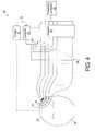
- FIG. 1is a schematic diagram of an ultrasound therapy system according to the invention.
- FIG. 2is a 3-dimensional rendering of a portion of a patient's skull.
- FIG. 3is a flow diagram of a process of determining excitation correction factors and exciting transducer elements using the determined factors.
- FIG. 4is a schematic diagram of another ultrasound therapy system according to the invention.
- FIG. 5is a flow diagram of a process of obtaining phase shift factors using the system shown in FIG. 4 .
- Energysuch as ultrasound energy
- a subjectsuch as a human or animal
- Arrays of radiating transducer elementsmay be used to transmit energy into the subject, and the amplitudes of the signals transmitted by the elements can affect how much energy penetrates the subject and the relative phases and amplitudes of energies transmitted can help to focus a distribution of energy in the subject.
- the phases and amplitudes of ultrasound signalsmay be affected/distorted by many causes such as different material properties of materials through which the signals are propagated. For example, different types of materials within a patient, e.g., bone, muscle, and fat, have different propagation and attenuation constants of ultrasound energy.
- phase and/or attenuation of ultrasound signalsmay affect the phase and/or attenuation of ultrasound signals. Because the signals from different transducer elements may encounter different thicknesses and contours of materials and possibly air-filled or liquid-filled pockets between transducer elements and a region to be imaged/treated, the phases of the signals from the transducer elements will often be distorted. The resulting phases and/or amplitudes will therefore often be different than desired if the transmission phases and/or amplitudes are not compensated for this distortion.
- Embodiments of the inventionprovide techniques for compensating for phase distortions and attenuation variances when treating a patient using ultrasound.
- imaging techniquessuch as computer tomography (CT), magnetic resonance imaging (MRI), etc.
- propertiessuch as thickness, density, and structure of materials are determined. It has been discovered that each of these properties affects the phase distortion of materials, so that phase corrections determined using all three properties will be better than those determined using only one or two of the properties.
- the determined properties for materials in a subject between transducer elements and a region to be treatedare inserted into formulas developed by the inventors.
- the formulasuse the determined properties and known characteristics, e.g., propagation speed, to calculate phase adjustments for each of the transducer elements.
- x-ray attenuationcan be related to phase distortion and acoustic attenuation. Formulas relating to x-ray attenuation to phase distortion and acoustic attenuation can be used to compensate for such variances by adjusting transmitted phase and amplitude accordingly.
- an ultrasound therapy system 10includes an imager 12 , a phased array 14 of n transducer elements 16 , a signal adjuster 18 , a controller 20 , and a frequency generator 22 .
- the system 10is configured to determine characteristics of a skull 28 of a patient 30 , and to apply ultrasound energy (e.g., in the range 0.01 MHz to 10 MHz) that is focused in the patient's brain.
- Signals to the arrayare provided by a driving arrangement similar to that reported in Daum et al., “Design and Evaluation of a Feedback Based Phased Array System for Ultrasound Surgery.” IEEE Trans. Ultrason. Ferroelectr. Freq. Control 45(2):431-4, 1998, but with a driving frequency selected between about 0.1 MHz and about 10 MHz.
- the power and phase to each transducer element 16may be manually controlled or automatically controlled using software and feedback.
- the array 14 of transducer elements 16is configured to be disposed on or near the external surface of the patient's skull 28 .
- the array 14is configured in a curved shape (e.g., spherical, although sections of other shapes are possible such as planar) conducive for being placed on the patient's head and for focusing ultrasound energy at a distance from the surface of the array 14 .
- the transducer elements 16 of the array 14are piezoelectric transducer elements arranged in the array 14 as shown.
- the transducer elementse.g., 1 cm 2 piezoelectric ceramic pieces
- the array 14may be formed from one or more pieces of piezocomposite material, or any material that converts electrical energy to acoustic energy.
- the transducer elements 16may be configured for electrical resonance at 50 ⁇ to help match input connector impedance.
- the array 14is coupled to the signal adjuster 18 that is further coupled to the frequency generator 22 .
- the frequency generator 22is configured to provide a common radio frequency (RF) signal as the input signal to the signal adjuster 18 .
- the radio frequency generator 22can be of any type that will produce the appropriate signals for the signal adjuster 18 .
- the generator 22may be a Model DS345 generator available from Stanford Research Systems.
- the radio frequency generator 22 and signal adjuster 18are configured to drive the individual transducer elements 16 of the array 14 at the same frequency, but at different phases (and possibly different amplitudes), in order to transmit ultrasound energy through the patient's skull 28 and focus the energy at a selected region within the patient's brain.
- the generator 22is coupled to the adjuster 18 to split the generator's output signal to provide n input signals to the signal adjuster 18 .
- phase shifters 26Coupled to receive each of the n input signals from the frequency generator 22 are n pairs of amplifiers 24 1 - 24 n and associated phase shifters 26 1 - 26 n of the signal adjuster 18 .
- Each pair of phase shifter 26 and amplifier 24represents a channel of the signal adjuster 18 .
- the phase shifters 26are configured to provide n independent output signals to the amplifiers 24 by altering or adjusting the phase (and possibly amplitude) of the incoming signals from the generator 22 by respective phase shift factors ⁇ 1 - ⁇ n .
- the phase shifters 26provide approximately 1 degree precision (8-bit resolution, although lower phase resolution may be adequate for many applications).
- the amplifiers 24 1 - 24 nare configured to amplify the signals from the phase shifters 26 and to provide the amplified signals to the transducer elements 16 through connections, e.g., coaxial cables, individually connecting the amplifiers 24 and the transducer elements 16 .
- An internal power meteris configured to monitor power supplied by the amplifiers 24 .
- phase shift factors ⁇ 1 - ⁇ n of the phase shifters 26provide steering of the ultrasound beam absent an object in the path of the ultrasound energy and also provide compensation for phase distortion in the ultrasound output by each transducer element 16 induced by the patient's skull.
- the component of each phase shift factor associated with steeringcan be computed using known techniques.
- the component of each phase shift factor ⁇ 1 - ⁇ n associated with phase distortioncompensates for perturbations and distortions introduced by the skull 28 , the skin/skull interface, the dura matter/skull interface, by variations in the skull thickness and by structural considerations such as air-filled or liquid-filled pockets in the skull 28 .
- phase shift factors ⁇ 1 - ⁇ nare summed in order to determine the composite phase shift factors ⁇ 1 - ⁇ n for the respective channels in order to focus ultrasound energy at a desired steering angle relative to, and distance from, the array 14 .
- the phase shift factors ⁇ 1 - ⁇ nare provided by the controller 20 .
- the controller 20is logic that may be provided by software, hardware, firmware, hardwiring, or combinations of any of these.
- the controller 20can be a general purpose, or special purpose, digital data processor programmed with software in a conventional manner in order to provide and apply the phase shift factors ⁇ 1 - ⁇ n to the phase shifters 26 , although other configurations may be used.
- the controller 20is configured to determine the phase shift factors ⁇ 1 - ⁇ n as described below based on information obtained from the imager 12 as indicated by arrow 32 .
- the informationincludes the thickness and density of the patient's skull 28 for each portion of the skull 28 between each transducer element 16 and the desired focal point in the patient's brain.
- Information from the imager 12is conveyed directly from the imager 12 because the imager 12 is configured to automatically analyze images and determine characteristics of interest from the images. Enough information is provided by the imager 12 to the controller 20 to determine the phase shift factors ⁇ 1 - ⁇ n .
- the controller 20is configured to manipulate images from the imager 12 .
- the controller 20is configured to produce a 3-dimensional rendering of the patient's skull 28 from 2-dimensional images received from the imager 12 and to determine skull thickness from the 3-dimensional rendering.
- the 3-dimensional renderingcan be divided by the controller 20 into voxels (a volume pixel of the 3-dimensional image).
- the imager 12is configured to obtain images of the interior of the patient's head, and in particular images that provide information regarding thickness, density, and structure of bone of the patient's skull 28 .
- the imager 12may be a Magnetic Resonance Imaging (MRI) device or Computer Tomography (CT) device.
- the imager 12is configured to scan the patient's skull 28 and provide information related to skull thickness, density and structure. This information includes 2-dimensional images of varying intensity from which 3-dimensional renderings can be made and from which thicknesses and densities can be determined and/or inferred. Three-dimensional image acquisition may also be possible and can be used.
- the imager 12is a CT device, the imager 12 can determine and provide the CT number (also called Hounsfield number) for each pixel in images provided by the imager 12 .
- CT numberalso called Hounsfield number
- the skull 28includes two layers 50 , 54 of trabecular bone and a layer 52 of cortical bone.
- a scan direction of the imager 12is defined as the Cartesian x-axis so that the image plane is defined by the y-axis and z-axis.
- two vectors 34 , 36 on the surface 38 of the skull 28are determined using the 3 rd nearest neighboring points on the surface in the x and y directions from the point of interest r 0 on the skull's surface 38 .
- the controller 20is configured to use the vectors 34 , 36 to calculate a vector 40 that is normal to the surface 38 .
- the controllercan calculate a scalar product of the vector 40 and a vector 42 that is the direction of propagation of energy from a transducer element 16 x .
- the three layers 50 , 52 , 54can be treated separately to determine phase compensation due to the thicknesses D 1 , D 2 , D 3 of the layers 50 , 52 , 54 as part of a three-layer model.
- the skull 28consists of individual homogeneous layers.
- the speed of soundis assumed to be 2.5 ⁇ 10 3 m/s for the central layer 52 and 2.9 ⁇ 10 3 m/s for the inner and outer layers 50 , 54 .
- each 0.15 mm 2 voxelis assigned an intensity value. It is assumed that the intensity is linearly proportional to bone density and density is scaled to MKS units using air and water in the image as reference intensities.
- Mean intensityis determined by summing the CT intensity values along the axis of propagation 42 inside the bone and dividing by the total number summed of voxels.
- the voxelsmay include air-filled or liquid-filled pockets. The sound speed for such voxels is assumed to be the speed of sound in water, or if air-filled, then complete reflection of the ultrasound can be assumed.
- Error due to skull densityhas been calculated as the difference between the measured phase and that given by Eq. (3) (for a single-layer model).
- An empirical correction factorhas been obtained by fitting (using a polynomial curve fit) percent error as a function of the mean intensity.
- ⁇contains the initial phase values obtained using Eq (3).
- the density and thickness measurementsmay also be applied toward adjustment of the skull sound speed.
- ⁇ ( ⁇ )is the measured phase shift as a function of density.
- a polynomial fit as shown in Eq. (5)is used by the controller 20 to find the speed of sound values.
- two sound speedsare calculated. These two speeds are the speed c i for the trabecular layers and the speed c ii of the cortical (central) bone.
- the polynomial fit for c i ( ⁇ )is performed using Eq. (5) over a series of trial functions for c ii .
- the final sound speedsare the c i ( ⁇ ) and c ii ( ⁇ ) that most closely correlate by standard deviation or other methods with direct skull measurements obtained by fitting a large skull sample.
- the controller 20uses information from the imager 12 to adjust the phase of the transducer elements 16 .
- the imager 12takes images of the patient's skull 28 . This may be done remotely in space, e.g., in another hospital, from the controller 20 .
- the imagertransmits information, e.g., intensities of portions of the image, related to skull thickness, density, and structure to the controller 20 . This transmission can be separated in time from when the imager 12 takes the image and can also be performed by human intervention, e.g., by recording the images on a CD and replaying the CD in the controller 20 .
- the controller 20manipulates this information to determine thicknesses of layers, and to identify the layers, of the patient's skull 28 by analyzing intensities of portions of the image.
- the controller 20determines excitation correction factors such as the phase shift factors ⁇ 1 - ⁇ n (or amplitude corrections as discussed below) and transmits the phase shift factors ⁇ 1 - ⁇ n to the adjuster 18 .
- the frequency generatorsupplies energy to the adjuster 18 .
- the adjuster 18adjusts the phase of the energy from the frequency generator 22 according to the phase shift factors ⁇ 1 - ⁇ n from the controller 20 .
- the adjusted energiesare sent to the transducer elements 16 that convert the energies into ultrasound waves and transmit these waves into the patient's skull 28 .
- Images from the imager 12can be supplied in real time and the amplitude and/or phasing of the energy applied to the patient 30 changed in response to the images.
- the power supplied to the patient's skull 28depends on the type of therapy. For ablation, approximately 2-3 kW for approximately 10 seconds using 64 transducer elements may be used. If more transducer elements 16 are used, then less total power may be used and vice versa. For opening the blood-brain barrier, about 100 times less power than for ablation may be used due to preformed gas bubbles in the area of interest. The ablation power can also be reduced by the preformed gas bubbles. Using bursts of energy has been found to reduce, if not eliminate, affects on phase due to standing waves that may occur if the transducer elements 16 constantly emit energy.
- the array 14 of transducer elements 16 shown in FIG. 1may contain fewer transducer elements 16 than shown.
- the phase shift factors ⁇ 1 - ⁇ nmay be pre-stored in the channels of signal adjuster 18 instead of being provided by the controller 20 .
- functions described as being performed by the controller 20could be performed by the imager 12 and vice versa, or by a person using the system 10 , e.g., calculating densities and providing input data to the controller 20 regarding phase shift factors ⁇ 1 - ⁇ n .
- a noninvasive process 70 for obtaining phase shift factors ⁇ 1 - ⁇ n using a system 90operates the transducer elements 16 in both transmit and receive modes.
- a controller 92is similar to the controller 20 (FIG. 1 ), but is also configured to control switches 94 1 - 94 n such that the transducer elements 16 are connected to the controller 92 in a receive mode and to the adjuster 18 in a transmit mode.
- the controller 92controls the switches 94 to be positioned such that one switch, e.g., switch 94 1 , is in the transmit mode.
- the frequency generator 22produces a low-frequency ultrasound wave train of about 5-30 cycles. Some of this wave train reflects off of the skull 28 and some of the wave train passes through the skull 28 into the patient's brain.
- the controller 92causes the switch 94 1 to switch into the receive mode, connecting the transducer element 16 1 to the controller 92 .
- the wave trainreflects off of the skull 28 and reflections are received by the transducer element 16 1 and recorded by the controller 92 .
- the propagation speeds and the pulse train lengthsare such that energy from a pulse train is still being transmitted into, and reflected by, the outer surface of the skull 28 when energy from that pulse train that was reflected by the inner surface of the skull 28 passes through the skull 28 toward the array 14 .
- the received reflections of the inner and outer surfacesare superimposed.
- stage 76a query is made as to whether a series of frequencies to be transmitted has been completed. If not, then the process 70 returns to stage 72 to transmit a different frequency in the series. If the series has been completed, with corresponding recorded amplitude data as a function of frequency, then the process 70 proceeds to stage 78 .
- the controller 92analyzes and processes the recorded information to determine the phase shift factors ⁇ 1 - ⁇ n .
- the controller 92deconvolves the recorded frequency response that includes the superimposed reflections from the interfaces at the inner and outer surfaces of the skull. The superimposed reflections produce a periodic appearance of local maxima and minima in the data as a function of frequency.
- Information from images, e.g., CT or MRI images,are used by the controller 92 to determine the locations of the inner and outer surfaces, and thus the skull thickness.
- the controller 92estimates the phase shift ( ⁇ ) using the distance, ⁇ f, between like extrema, e.g., peaks, according to:
- fis a frequency to be transmitted for which the phase correction is to be used
- dis the skull thickness determined from the image
- c 0is the speed of sound in water. Adjustments may be made to this phase shift using density correction techniques. The process 70 is repeated for the remainder of the transducer elements 16 .
- Phase shifts and acoustic attenuation due to transskull sonicationcan also be determined from analysis of CT images. For purposes of determining phase shift and acoustic attenuation, it can be assumed that there is essentially a one-to-one correlation between x-ray attenuation coefficient ⁇ and the speed of sound c in bone and between ⁇ and acoustic attenuation.
- Equations relating x-ray attenuation to phase and acoustic attenuationhave been developed as discussed below, with the equations including parameters determined from fitting to experimental data.
- Experimental datahas been determined by applying ultrasound to a pig skull sample using a 1′′ transducer element made by Panametrics of Waltham, Mass., operating at 730 kHz and positioned about 7 cm from a 0.6 mm hydrophone. The skull was attached to a 3-D positioning system and the transducer element was driven by a 10-cycle sinusoid signal produced by a waveform generator such as a Wavetek model 395 made by Wavetek Ltd. of Norwich, United Kingdom, or a waveform generator made by, e.g., Fluke Corporation of Everett, Wash.
- the hydrophone responsewas recorded on an HP54602 digital oscilloscope made by Hewlett Packard of Palo Alto, Calif. Measurements of the skull sample were obtained by immersing the sample in water and using dual-slice spiral acquisition with 0.5 mm slices.
- Phase shift through the skullcan be related to x-ray attenuation by assuming a formulaic relationship and fitting actual data to the formula.
- the x-ray attenuation coefficient ⁇is related to the CT number CT n according to:
- phase shift due to the passage through the boneis given by:
- the values of p 2 , p 1are obtained manually from intensity profiles drawn along the lines of propagation. These values may also be obtained automatically using well-known edge-detection techniques.
- Equation for ⁇can be modified to include a thickness-independent parameter.
- Equation 13can be modified to:
- Jis the phase shift at zero thickness and its non-zero value is probably due to experimental error.
- the value of ⁇can be used to adjust the phases of elements of an array of transducer elements such as the array 14 of the system 10 shown in FIG. 1 .
- Acoustic attenuation through the skullcan also be related to x-ray attenuation by assuming a formulaic relationship and fitting actual data to the formula.
- the acoustic attenuation through boneis given by:
- I and I 0are the acoustic intensities before and after the passage through the bone respectively and ⁇ AC (x) is the local acoustic attenuation coefficient.
- ⁇ AC (x)is the local acoustic attenuation coefficient.
- His a thickness-independent parameter that reflects the fraction of the intensity reflected at the interfaces (air-to-skull, between skull layers, and skull-to-brain).
- the magnitude of transmitted energycan be adjusted using the amplifiers 24 based on signals from the controller 20 .
- the imager 12supplies the CT numbers of images to the controller 20 that uses the CT numbers and the experimentally-determined values for A, B, C, J, E, F, G, & H to determine the phase correction factors ⁇ 1 - ⁇ n and amplitude adjustment factors for the amplifiers 24 .
- the systemotherwise operates generally as described above, with the adjuster 18 adjusting phase and amplitude of energy from the generator 22 as indicated by the controller 20 .
Landscapes
- Health & Medical Sciences (AREA)
- Life Sciences & Earth Sciences (AREA)
- Veterinary Medicine (AREA)
- Public Health (AREA)
- General Health & Medical Sciences (AREA)
- Nuclear Medicine, Radiotherapy & Molecular Imaging (AREA)
- Animal Behavior & Ethology (AREA)
- Radiology & Medical Imaging (AREA)
- Engineering & Computer Science (AREA)
- Biomedical Technology (AREA)
- Molecular Biology (AREA)
- Neurology (AREA)
- Heart & Thoracic Surgery (AREA)
- Surgery (AREA)
- Pathology (AREA)
- Biophysics (AREA)
- Physics & Mathematics (AREA)
- Medical Informatics (AREA)
- Ultra Sonic Daignosis Equipment (AREA)
- Surgical Instruments (AREA)
- Apparatus For Radiation Diagnosis (AREA)
- Magnetic Resonance Imaging Apparatus (AREA)
- Measuring Phase Differences (AREA)
- Measurement Of Resistance Or Impedance (AREA)
Abstract
Description


| TABLE 1 | |||
| A0 | 1.1424e-008 | ||
| A1 | −7.5377e-005 | ||
| A2 | 0.1645 | ||
| A3 | −118.689 | ||


Claims (57)


Priority Applications (7)
| Application Number | Priority Date | Filing Date | Title |
|---|---|---|---|
| US09/738,514US6612988B2 (en) | 2000-08-29 | 2000-12-15 | Ultrasound therapy |
| JP2002559121AJP4397588B2 (en) | 2000-12-15 | 2001-12-14 | Method and system for calculating phase and amplitude corrections in ultrasound therapy |
| DE60138655TDE60138655D1 (en) | 2000-12-15 | 2001-12-14 | METHOD AND SYSTEM FOR CALCULATING PHASE UN |
| EP01994284AEP1381430B1 (en) | 2000-12-15 | 2001-12-14 | Method and system for calculating phase and amplitude corrections in ultrasound therapy |
| AT01994284TATE430599T1 (en) | 2000-12-15 | 2001-12-14 | METHOD AND SYSTEM FOR CALCULATION OF PHASE AND AMPLITUDE CORRECTIONS IN ULTRASOUND THERAPY |
| PCT/US2001/048931WO2002058791A1 (en) | 2000-12-15 | 2001-12-14 | Method and system for calculating phase and amplitude corrections in ultrasound therapy |
| US10/228,418US6770031B2 (en) | 2000-12-15 | 2002-08-26 | Ultrasound therapy |
Applications Claiming Priority (2)
| Application Number | Priority Date | Filing Date | Title |
|---|---|---|---|
| US22885700P | 2000-08-29 | 2000-08-29 | |
| US09/738,514US6612988B2 (en) | 2000-08-29 | 2000-12-15 | Ultrasound therapy |
Related Child Applications (1)
| Application Number | Title | Priority Date | Filing Date |
|---|---|---|---|
| US10/228,418Continuation-In-PartUS6770031B2 (en) | 2000-12-15 | 2002-08-26 | Ultrasound therapy |
Publications (2)
| Publication Number | Publication Date |
|---|---|
| US20020111552A1 US20020111552A1 (en) | 2002-08-15 |
| US6612988B2true US6612988B2 (en) | 2003-09-02 |
Family
ID=24968335
Family Applications (1)
| Application Number | Title | Priority Date | Filing Date |
|---|---|---|---|
| US09/738,514Expired - LifetimeUS6612988B2 (en) | 2000-08-29 | 2000-12-15 | Ultrasound therapy |
Country Status (6)
| Country | Link |
|---|---|
| US (1) | US6612988B2 (en) |
| EP (1) | EP1381430B1 (en) |
| JP (1) | JP4397588B2 (en) |
| AT (1) | ATE430599T1 (en) |
| DE (1) | DE60138655D1 (en) |
| WO (1) | WO2002058791A1 (en) |
Cited By (103)
| Publication number | Priority date | Publication date | Assignee | Title |
|---|---|---|---|---|
| US20020065466A1 (en)* | 1998-03-20 | 2002-05-30 | Barbara Ann Karmanos Cancer Institute | Method and apparatus for high-resolution detection and characterization of medical pathologies |
| US20030204135A1 (en)* | 2002-04-30 | 2003-10-30 | Alexander Bystritsky | Methods for stimulating neurons |
| US20040254439A1 (en)* | 2003-06-11 | 2004-12-16 | Siemens Medical Solutions Usa, Inc. | System and method for adapting the behavior of a diagnostic medical ultrasound system based on anatomic features present in ultrasound images |
| US20060189972A1 (en)* | 2005-02-02 | 2006-08-24 | Gynesonics, Inc. | Method and device for uterine fibroid treatment |
| US20070065420A1 (en)* | 2005-08-23 | 2007-03-22 | Johnson Lanny L | Ultrasound Therapy Resulting in Bone Marrow Rejuvenation |
| US20070249936A1 (en)* | 2006-04-20 | 2007-10-25 | Gynesonics, Inc. | Devices and methods for treatment of tissue |
| US20070299370A1 (en)* | 2002-04-30 | 2007-12-27 | Alexander Bystritsky | Methods for modifying electrical currents in neuronal circuits |
| US20100160779A1 (en)* | 2006-08-11 | 2010-06-24 | Koninklijke Philips Electronics N.V. | Ultrasound system for cerebral blood flow imaging and microbubble-enhanced blood clot lysis |
| WO2010082135A1 (en) | 2009-01-13 | 2010-07-22 | Insightec Ltd. | Systems and methods for controlling ultrasound energy transmitted through non-uniform tissue and cooling of same |
| US7815571B2 (en) | 2006-04-20 | 2010-10-19 | Gynesonics, Inc. | Rigid delivery systems having inclined ultrasound and needle |
| US20100286518A1 (en)* | 2009-05-11 | 2010-11-11 | General Electric Company | Ultrasound system and method to deliver therapy based on user defined treatment spaces |
| US20100286519A1 (en)* | 2009-05-11 | 2010-11-11 | General Electric Company | Ultrasound system and method to automatically identify and treat adipose tissue |
| US20100286520A1 (en)* | 2009-05-11 | 2010-11-11 | General Electric Company | Ultrasound system and method to determine mechanical properties of a target region |
| US20100312150A1 (en)* | 2004-06-14 | 2010-12-09 | Mast T Douglas | System and method for medical treatment using ultrasound |
| US20110092800A1 (en)* | 2002-04-30 | 2011-04-21 | Seung-Schik Yoo | Methods for modifying electrical currents in neuronal circuits |
| US8002706B2 (en) | 2003-05-22 | 2011-08-23 | Insightec Ltd. | Acoustic beam forming in phased arrays including large numbers of transducer elements |
| WO2011135458A2 (en) | 2010-04-28 | 2011-11-03 | Insightec, Ltd. | Efficient ultrasound focusing |
| US8057408B2 (en) | 2005-09-22 | 2011-11-15 | The Regents Of The University Of Michigan | Pulsed cavitational ultrasound therapy |
| US8088067B2 (en) | 2002-12-23 | 2012-01-03 | Insightec Ltd. | Tissue aberration corrections in ultrasound therapy |
| US8088072B2 (en) | 2007-10-12 | 2012-01-03 | Gynesonics, Inc. | Methods and systems for controlled deployment of needles in tissue |
| US8137274B2 (en) | 1999-10-25 | 2012-03-20 | Kona Medical, Inc. | Methods to deliver high intensity focused ultrasound to target regions proximate blood vessels |
| US8167805B2 (en) | 2005-10-20 | 2012-05-01 | Kona Medical, Inc. | Systems and methods for ultrasound applicator station keeping |
| US8206300B2 (en) | 2008-08-26 | 2012-06-26 | Gynesonics, Inc. | Ablation device with articulated imaging transducer |
| US8235901B2 (en) | 2006-04-26 | 2012-08-07 | Insightec, Ltd. | Focused ultrasound system with far field tail suppression |
| US8251908B2 (en) | 2007-10-01 | 2012-08-28 | Insightec Ltd. | Motion compensated image-guided focused ultrasound therapy system |
| US8262574B2 (en) | 2009-02-27 | 2012-09-11 | Gynesonics, Inc. | Needle and tine deployment mechanism |
| US8295912B2 (en) | 2009-10-12 | 2012-10-23 | Kona Medical, Inc. | Method and system to inhibit a function of a nerve traveling with an artery |
| USRE43901E1 (en) | 2000-11-28 | 2013-01-01 | Insightec Ltd. | Apparatus for controlling thermal dosing in a thermal treatment system |
| US8353853B1 (en)* | 2003-01-24 | 2013-01-15 | Boston Scientific Scimed, Inc. | Encephalic insonication |
| US8368401B2 (en) | 2009-11-10 | 2013-02-05 | Insightec Ltd. | Techniques for correcting measurement artifacts in magnetic resonance thermometry |
| US8374674B2 (en) | 2009-10-12 | 2013-02-12 | Kona Medical, Inc. | Nerve treatment system |
| US8409099B2 (en) | 2004-08-26 | 2013-04-02 | Insightec Ltd. | Focused ultrasound system for surrounding a body tissue mass and treatment method |
| US8425424B2 (en) | 2008-11-19 | 2013-04-23 | Inightee Ltd. | Closed-loop clot lysis |
| US8469904B2 (en) | 2009-10-12 | 2013-06-25 | Kona Medical, Inc. | Energetic modulation of nerves |
| US8512262B2 (en) | 2009-10-12 | 2013-08-20 | Kona Medical, Inc. | Energetic modulation of nerves |
| US8517962B2 (en) | 2009-10-12 | 2013-08-27 | Kona Medical, Inc. | Energetic modulation of nerves |
| US8539813B2 (en) | 2009-09-22 | 2013-09-24 | The Regents Of The University Of Michigan | Gel phantoms for testing cavitational ultrasound (histotripsy) transducers |
| US8608672B2 (en) | 2005-11-23 | 2013-12-17 | Insightec Ltd. | Hierarchical switching in ultra-high density ultrasound array |
| US8617073B2 (en) | 2009-04-17 | 2013-12-31 | Insightec Ltd. | Focusing ultrasound into the brain through the skull by utilizing both longitudinal and shear waves |
| US8622937B2 (en) | 1999-11-26 | 2014-01-07 | Kona Medical, Inc. | Controlled high efficiency lesion formation using high intensity ultrasound |
| US8661873B2 (en) | 2009-10-14 | 2014-03-04 | Insightec Ltd. | Mapping ultrasound transducers |
| US20140194740A1 (en)* | 2013-01-07 | 2014-07-10 | Cerebrosonics, Llc | Emboli detection in the brain using a transcranial doppler photoacoustic device capable of vasculature and perfusion measurement |
| US8852103B2 (en) | 2011-10-17 | 2014-10-07 | Butterfly Network, Inc. | Transmissive imaging and related apparatus and methods |
| US8979871B2 (en) | 2009-08-13 | 2015-03-17 | Monteris Medical Corporation | Image-guided therapy of a tissue |
| US8986231B2 (en) | 2009-10-12 | 2015-03-24 | Kona Medical, Inc. | Energetic modulation of nerves |
| US8986211B2 (en) | 2009-10-12 | 2015-03-24 | Kona Medical, Inc. | Energetic modulation of nerves |
| US8992447B2 (en) | 2009-10-12 | 2015-03-31 | Kona Medical, Inc. | Energetic modulation of nerves |
| US9005143B2 (en) | 2009-10-12 | 2015-04-14 | Kona Medical, Inc. | External autonomic modulation |
| US9049783B2 (en) | 2012-04-13 | 2015-06-02 | Histosonics, Inc. | Systems and methods for obtaining large creepage isolation on printed circuit boards |
| US9061131B2 (en) | 2009-08-17 | 2015-06-23 | Histosonics, Inc. | Disposable acoustic coupling medium container |
| US9061133B2 (en) | 2012-12-27 | 2015-06-23 | Brainsonix Corporation | Focused ultrasonic transducer navigation system |
| US9144694B2 (en) | 2011-08-10 | 2015-09-29 | The Regents Of The University Of Michigan | Lesion generation through bone using histotripsy therapy without aberration correction |
| US9177543B2 (en) | 2009-08-26 | 2015-11-03 | Insightec Ltd. | Asymmetric ultrasound phased-array transducer for dynamic beam steering to ablate tissues in MRI |
| US9289154B2 (en) | 2009-08-19 | 2016-03-22 | Insightec Ltd. | Techniques for temperature measurement and corrections in long-term magnetic resonance thermometry |
| US9333038B2 (en) | 2000-06-15 | 2016-05-10 | Monteris Medical Corporation | Hyperthermia treatment and probe therefore |
| US9357977B2 (en) | 2006-01-12 | 2016-06-07 | Gynesonics, Inc. | Interventional deployment and imaging system |
| US9433383B2 (en) | 2014-03-18 | 2016-09-06 | Monteris Medical Corporation | Image-guided therapy of a tissue |
| US9504484B2 (en) | 2014-03-18 | 2016-11-29 | Monteris Medical Corporation | Image-guided therapy of a tissue |
| EP2964096A4 (en)* | 2013-03-04 | 2017-02-15 | Sunnybrook Health Sciences Centre | System and method for measuring and correcting ultrasound phase distortions induced by aberrating media |
| US9623266B2 (en) | 2009-08-04 | 2017-04-18 | Insightec Ltd. | Estimation of alignment parameters in magnetic-resonance-guided ultrasound focusing |
| US9636133B2 (en) | 2012-04-30 | 2017-05-02 | The Regents Of The University Of Michigan | Method of manufacturing an ultrasound system |
| US9667889B2 (en) | 2013-04-03 | 2017-05-30 | Butterfly Network, Inc. | Portable electronic devices with integrated imaging capabilities |
| US9743908B2 (en) | 2013-12-27 | 2017-08-29 | Chang Gung University | Processing system and processing method for confocally emitting and receiving ultrasound |
| US9763641B2 (en) | 2012-08-30 | 2017-09-19 | Delphinus Medical Technologies, Inc. | Method and system for imaging a volume of tissue with tissue boundary detection |
| US9852727B2 (en) | 2010-04-28 | 2017-12-26 | Insightec, Ltd. | Multi-segment ultrasound transducers |
| US9901753B2 (en) | 2009-08-26 | 2018-02-27 | The Regents Of The University Of Michigan | Ultrasound lithotripsy and histotripsy for using controlled bubble cloud cavitation in fractionating urinary stones |
| US9943708B2 (en) | 2009-08-26 | 2018-04-17 | Histosonics, Inc. | Automated control of micromanipulator arm for histotripsy prostate therapy while imaging via ultrasound transducers in real time |
| US9981148B2 (en) | 2010-10-22 | 2018-05-29 | Insightec, Ltd. | Adaptive active cooling during focused ultrasound treatment |
| US10058342B2 (en) | 2006-01-12 | 2018-08-28 | Gynesonics, Inc. | Devices and methods for treatment of tissue |
| US10123770B2 (en) | 2013-03-13 | 2018-11-13 | Delphinus Medical Technologies, Inc. | Patient support system |
| US10130828B2 (en) | 2005-06-21 | 2018-11-20 | Insightec Ltd. | Controlled, non-linear focused ultrasound treatment |
| US10143443B2 (en) | 2014-05-05 | 2018-12-04 | Delphinus Medical Technologies, Inc. | Method for representing tissue stiffness |
| US10201324B2 (en) | 2007-05-04 | 2019-02-12 | Delphinus Medical Technologies, Inc. | Patient interface system |
| US10219815B2 (en) | 2005-09-22 | 2019-03-05 | The Regents Of The University Of Michigan | Histotripsy for thrombolysis |
| US10285667B2 (en) | 2014-08-05 | 2019-05-14 | Delphinus Medical Technologies, Inc. | Method for generating an enhanced image of a volume of tissue |
| US10293187B2 (en) | 2013-07-03 | 2019-05-21 | Histosonics, Inc. | Histotripsy excitation sequences optimized for bubble cloud formation using shock scattering |
| US10327830B2 (en) | 2015-04-01 | 2019-06-25 | Monteris Medical Corporation | Cryotherapy, thermal therapy, temperature modulation therapy, and probe apparatus therefor |
| US10330782B2 (en) | 2014-11-07 | 2019-06-25 | Tessonics Corporation | Ultrasonic adaptive beamforming method and its application for transcranial imaging |
| US10512794B2 (en) | 2016-12-16 | 2019-12-24 | Brainsonix Corporation | Stereotactic frame |
| US10595819B2 (en) | 2006-04-20 | 2020-03-24 | Gynesonics, Inc. | Ablation device with articulated imaging transducer |
| US10675113B2 (en) | 2014-03-18 | 2020-06-09 | Monteris Medical Corporation | Automated therapy of a three-dimensional tissue region |
| US10743837B2 (en) | 2014-08-04 | 2020-08-18 | Delphinus Medical Technologies, Inc. | Ultrasound waveform tomography method and system |
| US10772681B2 (en) | 2009-10-12 | 2020-09-15 | Utsuka Medical Devices Co., Ltd. | Energy delivery to intraparenchymal regions of the kidney |
| US10780298B2 (en) | 2013-08-22 | 2020-09-22 | The Regents Of The University Of Michigan | Histotripsy using very short monopolar ultrasound pulses |
| US10925579B2 (en) | 2014-11-05 | 2021-02-23 | Otsuka Medical Devices Co., Ltd. | Systems and methods for real-time tracking of a target tissue using imaging before and during therapy delivery |
| US10974078B2 (en) | 2012-12-27 | 2021-04-13 | Brainsonix Corporation | Treating degenerative dementia with low intensity focused ultrasound pulsation (LIFUP) device |
| US10993770B2 (en) | 2016-11-11 | 2021-05-04 | Gynesonics, Inc. | Controlled treatment of tissue and dynamic interaction with, and comparison of, tissue and/or treatment data |
| US11058399B2 (en) | 2012-10-05 | 2021-07-13 | The Regents Of The University Of Michigan | Bubble-induced color doppler feedback during histotripsy |
| US11135454B2 (en) | 2015-06-24 | 2021-10-05 | The Regents Of The University Of Michigan | Histotripsy therapy systems and methods for the treatment of brain tissue |
| US11259825B2 (en) | 2006-01-12 | 2022-03-01 | Gynesonics, Inc. | Devices and methods for treatment of tissue |
| US11369809B2 (en) | 2014-06-20 | 2022-06-28 | The University Of Queensland | Neurodegenerative disease treatment |
| US11432900B2 (en) | 2013-07-03 | 2022-09-06 | Histosonics, Inc. | Articulating arm limiter for cavitational ultrasound therapy system |
| US11648424B2 (en) | 2018-11-28 | 2023-05-16 | Histosonics Inc. | Histotripsy systems and methods |
| US11759661B2 (en) | 2020-05-20 | 2023-09-19 | Brainsonix Corporation | Ultrasonic transducer treatment device |
| US11813485B2 (en) | 2020-01-28 | 2023-11-14 | The Regents Of The University Of Michigan | Systems and methods for histotripsy immunosensitization |
| WO2023172348A3 (en)* | 2022-01-04 | 2023-11-23 | University Of Utah Research Foundation | Systems and methods for modulation of deep brain circuits |
| US11998266B2 (en) | 2009-10-12 | 2024-06-04 | Otsuka Medical Devices Co., Ltd | Intravascular energy delivery |
| EP4438112A2 (en) | 2016-02-23 | 2024-10-02 | Sunnybrook Research Institute | Method of fabricating a transcranial headset for diagnostic or therapeutic procedures |
| US12179042B2 (en) | 2017-02-23 | 2024-12-31 | Oron Zachar | Transcranial ultrasound focusing |
| US12257446B2 (en) | 2020-08-24 | 2025-03-25 | Brainsonix Corporation | Systems and methods for neuromodulation of neuronal circuits using transcranial focused microwave pulses |
| US12318636B2 (en) | 2022-10-28 | 2025-06-03 | Histosonics, Inc. | Histotripsy systems and methods |
| US12343568B2 (en) | 2020-08-27 | 2025-07-01 | The Regents Of The University Of Michigan | Ultrasound transducer with transmit-receive capability for histotripsy |
| US12402802B2 (en) | 2011-08-31 | 2025-09-02 | Insightec Ltd. | Avoiding MRI-interference with co-existing systems |
Families Citing this family (11)
| Publication number | Priority date | Publication date | Assignee | Title |
|---|---|---|---|---|
| US9669239B2 (en) | 2011-07-27 | 2017-06-06 | Universite Pierre Et Marie Curie (Paris 6) | Device for treating the sensory capacity of a person and method of treatment with the help of such a device |
| US10456603B2 (en)* | 2014-12-10 | 2019-10-29 | Insightec, Ltd. | Systems and methods for optimizing transskull acoustic treatment |
| CN107106870B (en)* | 2014-12-11 | 2020-06-05 | 皇家飞利浦有限公司 | Ultrasonic Thrombolysis Ultrasonic Output Power Settings |
| WO2016100353A1 (en)* | 2014-12-15 | 2016-06-23 | Vesselon, Inc. | Automated ultrasound apparatus and method for noninvasive vessel recanalization treatment and monitoring |
| WO2018026738A1 (en)* | 2016-08-01 | 2018-02-08 | Bhaskar Ramamurthy | Ultrasound guided opening of blood-brain barrier |
| US11291866B2 (en)* | 2017-12-11 | 2022-04-05 | Insightec, Ltd. | Ultrasound focusing in dynamically changing media |
| MX2021011702A (en)* | 2019-03-25 | 2022-01-24 | Creaholic Sa | Treatment parameters for acoustic wave stimulation. |
| CN110160517B (en)* | 2019-05-22 | 2021-03-16 | 上海交通大学 | Real-time navigation method and system of ultrasonic transducer |
| US12318637B2 (en) | 2019-05-31 | 2025-06-03 | Sunnybrook Research Institute | Systems and methods for reducing thermal skull-induced aberrations during transcranial ultrasound therapeutic procedures |
| CN111135484A (en)* | 2020-01-14 | 2020-05-12 | 中国人民解放军总医院 | Magnetic resonance guided focused ultrasound energy prediction method for diagnosis and treatment of encephalopathy |
| DE102021212077A1 (en) | 2021-10-26 | 2023-04-27 | Siemens Healthcare Gmbh | Planning a therapeutic ultrasound treatment |
Citations (15)
| Publication number | Priority date | Publication date | Assignee | Title |
|---|---|---|---|---|
| US4817614A (en) | 1986-08-20 | 1989-04-04 | Siemens Aktiengesellschaft | Method and apparatus for adaptive focusing in a medical ultrasound imaging apparatus |
| US5052394A (en) | 1987-06-11 | 1991-10-01 | Commonwealth Scientific And Industrial Research Organization | Method and apparatus for ultrasonic beam compensation |
| US5113866A (en) | 1990-01-15 | 1992-05-19 | Siemens Aktiengesellschaft | Method for ultrasound imaging |
| US5381792A (en) | 1992-04-02 | 1995-01-17 | Kabushiki Kaisha Toshiba | Shock wave curing apparatus capable of correcting phase shifts contained in echo signals |
| US5487306A (en)* | 1994-09-26 | 1996-01-30 | General Electric Company | Phase aberration correction in phased-array imaging systems |
| US5531117A (en) | 1994-09-26 | 1996-07-02 | General Electric Company | Closed loop maximum likelihood phase aberration correction in phased-array imaging systems |
| US5590657A (en) | 1995-11-06 | 1997-01-07 | The Regents Of The University Of Michigan | Phased array ultrasound system and method for cardiac ablation |
| US5605154A (en)* | 1995-06-06 | 1997-02-25 | Duke University | Two-dimensional phase correction using a deformable ultrasonic transducer array |
| WO1998007373A1 (en) | 1996-08-21 | 1998-02-26 | Brigham & Women's Hospital | Methods and apparatus for delivery of noninvasive ultrasound brain therapy through intact skull |
| US5752515A (en) | 1996-08-21 | 1998-05-19 | Brigham & Women's Hospital | Methods and apparatus for image-guided ultrasound delivery of compounds through the blood-brain barrier |
| WO1999061903A2 (en) | 1998-05-29 | 1999-12-02 | Andreas Pesavento | System for rapidly calculating expansion images from high-frequency ultrasonic echo signals |
| US6013032A (en)* | 1998-03-13 | 2000-01-11 | Hewlett-Packard Company | Beamforming methods and apparatus for three-dimensional ultrasound imaging using two-dimensional transducer array |
| US6193663B1 (en) | 1997-12-18 | 2001-02-27 | Acuson Corporation | Diagnostic ultrasound imaging method and system with improved frame rate |
| US6419633B1 (en) | 2000-09-15 | 2002-07-16 | Koninklijke Philips Electronics N.V. | 2D ultrasonic transducer array for two dimensional and three dimensional imaging |
| US6425867B1 (en)* | 1998-09-18 | 2002-07-30 | University Of Washington | Noise-free real time ultrasonic imaging of a treatment site undergoing high intensity focused ultrasound therapy |
- 2000
- 2000-12-15USUS09/738,514patent/US6612988B2/ennot_activeExpired - Lifetime
- 2001
- 2001-12-14JPJP2002559121Apatent/JP4397588B2/ennot_activeExpired - Lifetime
- 2001-12-14EPEP01994284Apatent/EP1381430B1/ennot_activeExpired - Lifetime
- 2001-12-14DEDE60138655Tpatent/DE60138655D1/ennot_activeExpired - Lifetime
- 2001-12-14ATAT01994284Tpatent/ATE430599T1/ennot_activeIP Right Cessation
- 2001-12-14WOPCT/US2001/048931patent/WO2002058791A1/enactiveSearch and Examination
Patent Citations (15)
| Publication number | Priority date | Publication date | Assignee | Title |
|---|---|---|---|---|
| US4817614A (en) | 1986-08-20 | 1989-04-04 | Siemens Aktiengesellschaft | Method and apparatus for adaptive focusing in a medical ultrasound imaging apparatus |
| US5052394A (en) | 1987-06-11 | 1991-10-01 | Commonwealth Scientific And Industrial Research Organization | Method and apparatus for ultrasonic beam compensation |
| US5113866A (en) | 1990-01-15 | 1992-05-19 | Siemens Aktiengesellschaft | Method for ultrasound imaging |
| US5381792A (en) | 1992-04-02 | 1995-01-17 | Kabushiki Kaisha Toshiba | Shock wave curing apparatus capable of correcting phase shifts contained in echo signals |
| US5487306A (en)* | 1994-09-26 | 1996-01-30 | General Electric Company | Phase aberration correction in phased-array imaging systems |
| US5531117A (en) | 1994-09-26 | 1996-07-02 | General Electric Company | Closed loop maximum likelihood phase aberration correction in phased-array imaging systems |
| US5605154A (en)* | 1995-06-06 | 1997-02-25 | Duke University | Two-dimensional phase correction using a deformable ultrasonic transducer array |
| US5590657A (en) | 1995-11-06 | 1997-01-07 | The Regents Of The University Of Michigan | Phased array ultrasound system and method for cardiac ablation |
| WO1998007373A1 (en) | 1996-08-21 | 1998-02-26 | Brigham & Women's Hospital | Methods and apparatus for delivery of noninvasive ultrasound brain therapy through intact skull |
| US5752515A (en) | 1996-08-21 | 1998-05-19 | Brigham & Women's Hospital | Methods and apparatus for image-guided ultrasound delivery of compounds through the blood-brain barrier |
| US6193663B1 (en) | 1997-12-18 | 2001-02-27 | Acuson Corporation | Diagnostic ultrasound imaging method and system with improved frame rate |
| US6013032A (en)* | 1998-03-13 | 2000-01-11 | Hewlett-Packard Company | Beamforming methods and apparatus for three-dimensional ultrasound imaging using two-dimensional transducer array |
| WO1999061903A2 (en) | 1998-05-29 | 1999-12-02 | Andreas Pesavento | System for rapidly calculating expansion images from high-frequency ultrasonic echo signals |
| US6425867B1 (en)* | 1998-09-18 | 2002-07-30 | University Of Washington | Noise-free real time ultrasonic imaging of a treatment site undergoing high intensity focused ultrasound therapy |
| US6419633B1 (en) | 2000-09-15 | 2002-07-16 | Koninklijke Philips Electronics N.V. | 2D ultrasonic transducer array for two dimensional and three dimensional imaging |
Non-Patent Citations (5)
| Title |
|---|
| Hynynen, et al., "Demonstration of Potential Noninvasive Ultrasound Brain Therapy Through an Intact Skull", Ultrasound in Medicine and Biology, vol. 24, No. 2, pp. 275-283, 1998. |
| Hynynen, Kullervo, "Trans-skull Ultrasound Therapy: The Feasibility of Using Image-Derived Skull Thickness Information to Correct the Phase Distortion", IEEE Trans. on Ultrasonics, Ferroelectrics, and Freq. Control, pp. 752-755, vol. 46, No. 3, May 1999. |
| Notification of Transmittal of The International Search Report or the Declaration, mailed Jul. 15, 2002. |
| Sun, et al., "Focusing of Therapeutic Ultrasound Through A Human Skull: A Numerical Study", J. Acoust. Soc. Am. 104(3) pt. 1, pp. 1705-1715, Sep. 1998. |
| Sun, et al., "The Potential of Transskull Ultrasound Therapy and Surgery Using the Maximum Available Skull Surface Area", J. Acoust. Soc. Am. 105(4), pp. 2519-2527, Apr. 1999. |
Cited By (202)
| Publication number | Priority date | Publication date | Assignee | Title |
|---|---|---|---|---|
| US20020065466A1 (en)* | 1998-03-20 | 2002-05-30 | Barbara Ann Karmanos Cancer Institute | Method and apparatus for high-resolution detection and characterization of medical pathologies |
| US6728567B2 (en)* | 1998-03-20 | 2004-04-27 | Barbara Ann Karmanos Cancer Institute | Method and apparatus for high-resolution detection and characterization of medical pathologies |
| US8137274B2 (en) | 1999-10-25 | 2012-03-20 | Kona Medical, Inc. | Methods to deliver high intensity focused ultrasound to target regions proximate blood vessels |
| US8277398B2 (en) | 1999-10-25 | 2012-10-02 | Kona Medical, Inc. | Methods and devices to target vascular targets with high intensity focused ultrasound |
| US8388535B2 (en) | 1999-10-25 | 2013-03-05 | Kona Medical, Inc. | Methods and apparatus for focused ultrasound application |
| US8622937B2 (en) | 1999-11-26 | 2014-01-07 | Kona Medical, Inc. | Controlled high efficiency lesion formation using high intensity ultrasound |
| US9333038B2 (en) | 2000-06-15 | 2016-05-10 | Monteris Medical Corporation | Hyperthermia treatment and probe therefore |
| US9387042B2 (en) | 2000-06-15 | 2016-07-12 | Monteris Medical Corporation | Hyperthermia treatment and probe therefor |
| USRE43901E1 (en) | 2000-11-28 | 2013-01-01 | Insightec Ltd. | Apparatus for controlling thermal dosing in a thermal treatment system |
| US20070299370A1 (en)* | 2002-04-30 | 2007-12-27 | Alexander Bystritsky | Methods for modifying electrical currents in neuronal circuits |
| US7283861B2 (en)* | 2002-04-30 | 2007-10-16 | Alexander Bystritsky | Methods for modifying electrical currents in neuronal circuits |
| US9592409B2 (en) | 2002-04-30 | 2017-03-14 | The Regents Of The University Of California | Methods for modifying electrical currents in neuronal circuits |
| US8086296B2 (en) | 2002-04-30 | 2011-12-27 | Brainsonix Corporation | Methods for modifying electrical currents in neuronal circuits |
| US20110092800A1 (en)* | 2002-04-30 | 2011-04-21 | Seung-Schik Yoo | Methods for modifying electrical currents in neuronal circuits |
| US20030204135A1 (en)* | 2002-04-30 | 2003-10-30 | Alexander Bystritsky | Methods for stimulating neurons |
| US8088067B2 (en) | 2002-12-23 | 2012-01-03 | Insightec Ltd. | Tissue aberration corrections in ultrasound therapy |
| US8353853B1 (en)* | 2003-01-24 | 2013-01-15 | Boston Scientific Scimed, Inc. | Encephalic insonication |
| US8002706B2 (en) | 2003-05-22 | 2011-08-23 | Insightec Ltd. | Acoustic beam forming in phased arrays including large numbers of transducer elements |
| US20040254439A1 (en)* | 2003-06-11 | 2004-12-16 | Siemens Medical Solutions Usa, Inc. | System and method for adapting the behavior of a diagnostic medical ultrasound system based on anatomic features present in ultrasound images |
| US7092749B2 (en)* | 2003-06-11 | 2006-08-15 | Siemens Medical Solutions Usa, Inc. | System and method for adapting the behavior of a diagnostic medical ultrasound system based on anatomic features present in ultrasound images |
| US9132287B2 (en)* | 2004-06-14 | 2015-09-15 | T. Douglas Mast | System and method for ultrasound treatment using grating lobes |
| US20100312150A1 (en)* | 2004-06-14 | 2010-12-09 | Mast T Douglas | System and method for medical treatment using ultrasound |
| US8409099B2 (en) | 2004-08-26 | 2013-04-02 | Insightec Ltd. | Focused ultrasound system for surrounding a body tissue mass and treatment method |
| US11419668B2 (en) | 2005-02-02 | 2022-08-23 | Gynesonics, Inc. | Method and device for uterine fibroid treatment |
| US9987080B2 (en) | 2005-02-02 | 2018-06-05 | Gynesonics, Inc. | Method and device for uterine fibroid treatment |
| US7918795B2 (en) | 2005-02-02 | 2011-04-05 | Gynesonics, Inc. | Method and device for uterine fibroid treatment |
| US10182862B2 (en) | 2005-02-02 | 2019-01-22 | Gynesonics, Inc. | Method and device for uterine fibroid treatment |
| US20060189972A1 (en)* | 2005-02-02 | 2006-08-24 | Gynesonics, Inc. | Method and device for uterine fibroid treatment |
| US11950837B2 (en) | 2005-02-02 | 2024-04-09 | Gynesonics, Inc. | Method and device for uterine fibroid treatment |
| US12414813B2 (en) | 2005-02-02 | 2025-09-16 | Gynesonics, Inc. | Method and device for uterine fibroid treatment |
| US9808310B2 (en) | 2005-02-02 | 2017-11-07 | Gynesonics, Inc. | Method and device for uterine fibroid treatment |
| US10130828B2 (en) | 2005-06-21 | 2018-11-20 | Insightec Ltd. | Controlled, non-linear focused ultrasound treatment |
| US20070065420A1 (en)* | 2005-08-23 | 2007-03-22 | Johnson Lanny L | Ultrasound Therapy Resulting in Bone Marrow Rejuvenation |
| US11364042B2 (en) | 2005-09-22 | 2022-06-21 | The Regents Of The University Of Michigan | Histotripsy for thrombolysis |
| US11701134B2 (en) | 2005-09-22 | 2023-07-18 | The Regents Of The University Of Michigan | Histotripsy for thrombolysis |
| US12150661B2 (en) | 2005-09-22 | 2024-11-26 | The Regents Of The University Of Michigan | Histotripsy for thrombolysis |
| US8057408B2 (en) | 2005-09-22 | 2011-11-15 | The Regents Of The University Of Michigan | Pulsed cavitational ultrasound therapy |
| US12303152B2 (en) | 2005-09-22 | 2025-05-20 | The Regents Of The University Of Michigan | Histotripsy for thrombolysis |
| US10219815B2 (en) | 2005-09-22 | 2019-03-05 | The Regents Of The University Of Michigan | Histotripsy for thrombolysis |
| US9642634B2 (en) | 2005-09-22 | 2017-05-09 | The Regents Of The University Of Michigan | Pulsed cavitational ultrasound therapy |
| US9220488B2 (en) | 2005-10-20 | 2015-12-29 | Kona Medical, Inc. | System and method for treating a therapeutic site |
| US8372009B2 (en) | 2005-10-20 | 2013-02-12 | Kona Medical, Inc. | System and method for treating a therapeutic site |
| US8167805B2 (en) | 2005-10-20 | 2012-05-01 | Kona Medical, Inc. | Systems and methods for ultrasound applicator station keeping |
| US8608672B2 (en) | 2005-11-23 | 2013-12-17 | Insightec Ltd. | Hierarchical switching in ultra-high density ultrasound array |
| US9517047B2 (en) | 2006-01-12 | 2016-12-13 | Gynesonics, Inc. | Interventional deployment and imaging system |
| US10058342B2 (en) | 2006-01-12 | 2018-08-28 | Gynesonics, Inc. | Devices and methods for treatment of tissue |
| US9357977B2 (en) | 2006-01-12 | 2016-06-07 | Gynesonics, Inc. | Interventional deployment and imaging system |
| US11259825B2 (en) | 2006-01-12 | 2022-03-01 | Gynesonics, Inc. | Devices and methods for treatment of tissue |
| US7815571B2 (en) | 2006-04-20 | 2010-10-19 | Gynesonics, Inc. | Rigid delivery systems having inclined ultrasound and needle |
| US12048583B2 (en) | 2006-04-20 | 2024-07-30 | Gynesonics, Inc. | Ablation device with articulated imaging transducer |
| US20070249936A1 (en)* | 2006-04-20 | 2007-10-25 | Gynesonics, Inc. | Devices and methods for treatment of tissue |
| US10610197B2 (en) | 2006-04-20 | 2020-04-07 | Gynesonics, Inc. | Ablation device with articulated imaging transducer |
| US8506485B2 (en) | 2006-04-20 | 2013-08-13 | Gynesonics, Inc | Devices and methods for treatment of tissue |
| US10595819B2 (en) | 2006-04-20 | 2020-03-24 | Gynesonics, Inc. | Ablation device with articulated imaging transducer |
| US7874986B2 (en) | 2006-04-20 | 2011-01-25 | Gynesonics, Inc. | Methods and devices for visualization and ablation of tissue |
| US8235901B2 (en) | 2006-04-26 | 2012-08-07 | Insightec, Ltd. | Focused ultrasound system with far field tail suppression |
| US9630028B2 (en)* | 2006-08-11 | 2017-04-25 | Koninklijke Philips N.V. | Ultrasound system for cerebral blood flow imaging and microbubble-enhanced blood clot lysis |
| US20100160779A1 (en)* | 2006-08-11 | 2010-06-24 | Koninklijke Philips Electronics N.V. | Ultrasound system for cerebral blood flow imaging and microbubble-enhanced blood clot lysis |
| US10363012B2 (en) | 2006-08-11 | 2019-07-30 | Koninklijke Philips N.V. | Ultrasound system for cerebral blood flow imaging and microbubble-enhanced blood clot lysis |
| US10201324B2 (en) | 2007-05-04 | 2019-02-12 | Delphinus Medical Technologies, Inc. | Patient interface system |
| US12161505B2 (en) | 2007-05-04 | 2024-12-10 | Delphinus Medical Technologies, Inc. | Patient interface system |
| US8251908B2 (en) | 2007-10-01 | 2012-08-28 | Insightec Ltd. | Motion compensated image-guided focused ultrasound therapy system |
| US8548561B2 (en) | 2007-10-01 | 2013-10-01 | Insightec Ltd. | Motion compensated image-guided focused ultrasound therapy system |
| US11826207B2 (en) | 2007-10-12 | 2023-11-28 | Gynesonics, Inc | Methods and systems for controlled deployment of needles in tissue |
| US8262577B2 (en) | 2007-10-12 | 2012-09-11 | Gynesonics, Inc. | Methods and systems for controlled deployment of needles in tissue |
| US11925512B2 (en) | 2007-10-12 | 2024-03-12 | Gynesonics, Inc. | Methods and systems for controlled deployment of needles in tissue |
| US8088072B2 (en) | 2007-10-12 | 2012-01-03 | Gynesonics, Inc. | Methods and systems for controlled deployment of needles in tissue |
| US11096761B2 (en) | 2007-10-12 | 2021-08-24 | Gynesonics, Inc. | Methods and systems for controlled deployment of needles in tissue |
| US11096760B2 (en) | 2007-10-12 | 2021-08-24 | Gynesonics, Inc. | Methods and systems for controlled deployment of needles in tissue |
| US8206300B2 (en) | 2008-08-26 | 2012-06-26 | Gynesonics, Inc. | Ablation device with articulated imaging transducer |
| US8425424B2 (en) | 2008-11-19 | 2013-04-23 | Inightee Ltd. | Closed-loop clot lysis |
| WO2010082135A1 (en) | 2009-01-13 | 2010-07-22 | Insightec Ltd. | Systems and methods for controlling ultrasound energy transmitted through non-uniform tissue and cooling of same |
| US8262574B2 (en) | 2009-02-27 | 2012-09-11 | Gynesonics, Inc. | Needle and tine deployment mechanism |
| US11564735B2 (en) | 2009-02-27 | 2023-01-31 | Gynesonics, Inc. | Needle and fine deployment mechanism |
| US11992258B2 (en) | 2009-02-27 | 2024-05-28 | Gynesonics, Inc. | Needle and tine deployment mechanism |
| US10321951B2 (en) | 2009-02-27 | 2019-06-18 | Gynesonics, Inc. | Needle and tine deployment mechanism |
| US8617073B2 (en) | 2009-04-17 | 2013-12-31 | Insightec Ltd. | Focusing ultrasound into the brain through the skull by utilizing both longitudinal and shear waves |
| US20100286520A1 (en)* | 2009-05-11 | 2010-11-11 | General Electric Company | Ultrasound system and method to determine mechanical properties of a target region |
| US20100286519A1 (en)* | 2009-05-11 | 2010-11-11 | General Electric Company | Ultrasound system and method to automatically identify and treat adipose tissue |
| US20100286518A1 (en)* | 2009-05-11 | 2010-11-11 | General Electric Company | Ultrasound system and method to deliver therapy based on user defined treatment spaces |
| US9623266B2 (en) | 2009-08-04 | 2017-04-18 | Insightec Ltd. | Estimation of alignment parameters in magnetic-resonance-guided ultrasound focusing |
| US8979871B2 (en) | 2009-08-13 | 2015-03-17 | Monteris Medical Corporation | Image-guided therapy of a tissue |
| US10610317B2 (en) | 2009-08-13 | 2020-04-07 | Monteris Medical Corporation | Image-guided therapy of a tissue |
| US9271794B2 (en) | 2009-08-13 | 2016-03-01 | Monteris Medical Corporation | Monitoring and noise masking of thermal therapy |
| US10188462B2 (en) | 2009-08-13 | 2019-01-29 | Monteris Medical Corporation | Image-guided therapy of a tissue |
| US9211157B2 (en) | 2009-08-13 | 2015-12-15 | Monteris Medical Corporation | Probe driver |
| US9510909B2 (en) | 2009-08-13 | 2016-12-06 | Monteris Medical Corporation | Image-guide therapy of a tissue |
| US9526923B2 (en) | 2009-08-17 | 2016-12-27 | Histosonics, Inc. | Disposable acoustic coupling medium container |
| US9061131B2 (en) | 2009-08-17 | 2015-06-23 | Histosonics, Inc. | Disposable acoustic coupling medium container |
| US9289154B2 (en) | 2009-08-19 | 2016-03-22 | Insightec Ltd. | Techniques for temperature measurement and corrections in long-term magnetic resonance thermometry |
| US9943708B2 (en) | 2009-08-26 | 2018-04-17 | Histosonics, Inc. | Automated control of micromanipulator arm for histotripsy prostate therapy while imaging via ultrasound transducers in real time |
| US9901753B2 (en) | 2009-08-26 | 2018-02-27 | The Regents Of The University Of Michigan | Ultrasound lithotripsy and histotripsy for using controlled bubble cloud cavitation in fractionating urinary stones |
| US9177543B2 (en) | 2009-08-26 | 2015-11-03 | Insightec Ltd. | Asymmetric ultrasound phased-array transducer for dynamic beam steering to ablate tissues in MRI |
| US8539813B2 (en) | 2009-09-22 | 2013-09-24 | The Regents Of The University Of Michigan | Gel phantoms for testing cavitational ultrasound (histotripsy) transducers |
| US9125642B2 (en) | 2009-10-12 | 2015-09-08 | Kona Medical, Inc. | External autonomic modulation |
| US8986231B2 (en) | 2009-10-12 | 2015-03-24 | Kona Medical, Inc. | Energetic modulation of nerves |
| US10772681B2 (en) | 2009-10-12 | 2020-09-15 | Utsuka Medical Devices Co., Ltd. | Energy delivery to intraparenchymal regions of the kidney |
| US9119951B2 (en) | 2009-10-12 | 2015-09-01 | Kona Medical, Inc. | Energetic modulation of nerves |
| US8295912B2 (en) | 2009-10-12 | 2012-10-23 | Kona Medical, Inc. | Method and system to inhibit a function of a nerve traveling with an artery |
| US9358401B2 (en) | 2009-10-12 | 2016-06-07 | Kona Medical, Inc. | Intravascular catheter to deliver unfocused energy to nerves surrounding a blood vessel |
| US11998266B2 (en) | 2009-10-12 | 2024-06-04 | Otsuka Medical Devices Co., Ltd | Intravascular energy delivery |
| US9005143B2 (en) | 2009-10-12 | 2015-04-14 | Kona Medical, Inc. | External autonomic modulation |
| US9579518B2 (en) | 2009-10-12 | 2017-02-28 | Kona Medical, Inc. | Nerve treatment system |
| US8992447B2 (en) | 2009-10-12 | 2015-03-31 | Kona Medical, Inc. | Energetic modulation of nerves |
| US8986211B2 (en) | 2009-10-12 | 2015-03-24 | Kona Medical, Inc. | Energetic modulation of nerves |
| US9119952B2 (en) | 2009-10-12 | 2015-09-01 | Kona Medical, Inc. | Methods and devices to modulate the autonomic nervous system via the carotid body or carotid sinus |
| US8715209B2 (en) | 2009-10-12 | 2014-05-06 | Kona Medical, Inc. | Methods and devices to modulate the autonomic nervous system with ultrasound |
| US11154356B2 (en) | 2009-10-12 | 2021-10-26 | Otsuka Medical Devices Co., Ltd. | Intravascular energy delivery |
| US8556834B2 (en) | 2009-10-12 | 2013-10-15 | Kona Medical, Inc. | Flow directed heating of nervous structures |
| US9352171B2 (en) | 2009-10-12 | 2016-05-31 | Kona Medical, Inc. | Nerve treatment system |
| US8517962B2 (en) | 2009-10-12 | 2013-08-27 | Kona Medical, Inc. | Energetic modulation of nerves |
| US9174065B2 (en) | 2009-10-12 | 2015-11-03 | Kona Medical, Inc. | Energetic modulation of nerves |
| US8512262B2 (en) | 2009-10-12 | 2013-08-20 | Kona Medical, Inc. | Energetic modulation of nerves |
| US8469904B2 (en) | 2009-10-12 | 2013-06-25 | Kona Medical, Inc. | Energetic modulation of nerves |
| US8374674B2 (en) | 2009-10-12 | 2013-02-12 | Kona Medical, Inc. | Nerve treatment system |
| US9199097B2 (en) | 2009-10-12 | 2015-12-01 | Kona Medical, Inc. | Energetic modulation of nerves |
| US8661873B2 (en) | 2009-10-14 | 2014-03-04 | Insightec Ltd. | Mapping ultrasound transducers |
| US9412357B2 (en) | 2009-10-14 | 2016-08-09 | Insightec Ltd. | Mapping ultrasound transducers |
| US9541621B2 (en) | 2009-11-10 | 2017-01-10 | Insightec, Ltd. | Techniques for correcting measurement artifacts in magnetic resonance thermometry |
| US8368401B2 (en) | 2009-11-10 | 2013-02-05 | Insightec Ltd. | Techniques for correcting measurement artifacts in magnetic resonance thermometry |
| US11134846B2 (en) | 2010-02-17 | 2021-10-05 | The Regents Of The University Of California | Methods and systems for modifying electrical currents in neuronal circuits |
| US12178546B2 (en) | 2010-02-17 | 2024-12-31 | The Regents Of The University Of California | Methods and systems for modifying electrical currents in neuronal circuits |
| WO2011135458A2 (en) | 2010-04-28 | 2011-11-03 | Insightec, Ltd. | Efficient ultrasound focusing |
| US8932237B2 (en) | 2010-04-28 | 2015-01-13 | Insightec, Ltd. | Efficient ultrasound focusing |
| US9852727B2 (en) | 2010-04-28 | 2017-12-26 | Insightec, Ltd. | Multi-segment ultrasound transducers |
| US9981148B2 (en) | 2010-10-22 | 2018-05-29 | Insightec, Ltd. | Adaptive active cooling during focused ultrasound treatment |
| US10071266B2 (en) | 2011-08-10 | 2018-09-11 | The Regents Of The University Of Michigan | Lesion generation through bone using histotripsy therapy without aberration correction |
| US9144694B2 (en) | 2011-08-10 | 2015-09-29 | The Regents Of The University Of Michigan | Lesion generation through bone using histotripsy therapy without aberration correction |
| US12402802B2 (en) | 2011-08-31 | 2025-09-02 | Insightec Ltd. | Avoiding MRI-interference with co-existing systems |
| US9149255B2 (en) | 2011-10-17 | 2015-10-06 | Butterfly Network, Inc. | Image-guided high intensity focused ultrasound and related apparatus and methods |
| US9028412B2 (en) | 2011-10-17 | 2015-05-12 | Butterfly Network, Inc. | Transmissive imaging and related apparatus and methods |
| US9268015B2 (en) | 2011-10-17 | 2016-02-23 | Butterfly Network, Inc. | Image-guided high intensity focused ultrasound and related apparatus and methods |
| US9022936B2 (en) | 2011-10-17 | 2015-05-05 | Butterfly Network, Inc. | Transmissive imaging and related apparatus and methods |
| US9268014B2 (en) | 2011-10-17 | 2016-02-23 | Butterfly Network, Inc. | Transmissive imaging and related apparatus and methods |
| US9155521B2 (en) | 2011-10-17 | 2015-10-13 | Butterfly Network, Inc. | Transmissive imaging and related apparatus and methods |
| US8852103B2 (en) | 2011-10-17 | 2014-10-07 | Butterfly Network, Inc. | Transmissive imaging and related apparatus and methods |
| US9033884B2 (en) | 2011-10-17 | 2015-05-19 | Butterfly Network, Inc. | Transmissive imaging and related apparatus and methods |
| US9247924B2 (en) | 2011-10-17 | 2016-02-02 | Butterfly Networks, Inc. | Transmissive imaging and related apparatus and methods |
| US9198637B2 (en) | 2011-10-17 | 2015-12-01 | Butterfly Network, Inc. | Transmissive imaging and related apparatus and methods |
| US9049783B2 (en) | 2012-04-13 | 2015-06-02 | Histosonics, Inc. | Systems and methods for obtaining large creepage isolation on printed circuit boards |
| US9636133B2 (en) | 2012-04-30 | 2017-05-02 | The Regents Of The University Of Michigan | Method of manufacturing an ultrasound system |
| US10548678B2 (en) | 2012-06-27 | 2020-02-04 | Monteris Medical Corporation | Method and device for effecting thermal therapy of a tissue |
| US9763641B2 (en) | 2012-08-30 | 2017-09-19 | Delphinus Medical Technologies, Inc. | Method and system for imaging a volume of tissue with tissue boundary detection |
| US11058399B2 (en) | 2012-10-05 | 2021-07-13 | The Regents Of The University Of Michigan | Bubble-induced color doppler feedback during histotripsy |
| US11766576B2 (en) | 2012-12-27 | 2023-09-26 | Brainsonix Corporation | Treating degenerative dementia with low intensity focused ultrasound pulsation (LIFUP) device |
| US10792519B2 (en) | 2012-12-27 | 2020-10-06 | Brainsonix Corporation | Focused ultrasonic transducer navigation system |
| US12350524B2 (en) | 2012-12-27 | 2025-07-08 | Brainsonix Corporation | Treating degenerative dementia with low intensity focused ultrasound pulsation (LIFUP) device |
| US10974078B2 (en) | 2012-12-27 | 2021-04-13 | Brainsonix Corporation | Treating degenerative dementia with low intensity focused ultrasound pulsation (LIFUP) device |
| US9061133B2 (en) | 2012-12-27 | 2015-06-23 | Brainsonix Corporation | Focused ultrasonic transducer navigation system |
| US9630029B2 (en) | 2012-12-27 | 2017-04-25 | Brainsonix Corporation | Focused ultrasonic transducer navigation system |
| US20140194740A1 (en)* | 2013-01-07 | 2014-07-10 | Cerebrosonics, Llc | Emboli detection in the brain using a transcranial doppler photoacoustic device capable of vasculature and perfusion measurement |
| EP2964096A4 (en)* | 2013-03-04 | 2017-02-15 | Sunnybrook Health Sciences Centre | System and method for measuring and correcting ultrasound phase distortions induced by aberrating media |
| US11464482B2 (en) | 2013-03-04 | 2022-10-11 | Sunnybrook Research Institute | System and method for measuring and correcting ultrasound phase distortions induced by aberrating media |
| US11064974B2 (en) | 2013-03-13 | 2021-07-20 | Delphinus Medical Technologies, Inc. | Patient interface system |
| US10123770B2 (en) | 2013-03-13 | 2018-11-13 | Delphinus Medical Technologies, Inc. | Patient support system |
| US9667889B2 (en) | 2013-04-03 | 2017-05-30 | Butterfly Network, Inc. | Portable electronic devices with integrated imaging capabilities |
| US10293187B2 (en) | 2013-07-03 | 2019-05-21 | Histosonics, Inc. | Histotripsy excitation sequences optimized for bubble cloud formation using shock scattering |
| US11432900B2 (en) | 2013-07-03 | 2022-09-06 | Histosonics, Inc. | Articulating arm limiter for cavitational ultrasound therapy system |
| US11819712B2 (en) | 2013-08-22 | 2023-11-21 | The Regents Of The University Of Michigan | Histotripsy using very short ultrasound pulses |
| US10780298B2 (en) | 2013-08-22 | 2020-09-22 | The Regents Of The University Of Michigan | Histotripsy using very short monopolar ultrasound pulses |
| US12350525B2 (en) | 2013-08-22 | 2025-07-08 | The Regents Of The University Of Michigan | Histotripsy using very short ultrasound pulses |
| US9743908B2 (en) | 2013-12-27 | 2017-08-29 | Chang Gung University | Processing system and processing method for confocally emitting and receiving ultrasound |
| US9504484B2 (en) | 2014-03-18 | 2016-11-29 | Monteris Medical Corporation | Image-guided therapy of a tissue |
| US9700342B2 (en) | 2014-03-18 | 2017-07-11 | Monteris Medical Corporation | Image-guided therapy of a tissue |
| US9486170B2 (en) | 2014-03-18 | 2016-11-08 | Monteris Medical Corporation | Image-guided therapy of a tissue |
| US10092367B2 (en) | 2014-03-18 | 2018-10-09 | Monteris Medical Corporation | Image-guided therapy of a tissue |
| US9433383B2 (en) | 2014-03-18 | 2016-09-06 | Monteris Medical Corporation | Image-guided therapy of a tissue |
| US10342632B2 (en) | 2014-03-18 | 2019-07-09 | Monteris Medical Corporation | Image-guided therapy of a tissue |
| US10675113B2 (en) | 2014-03-18 | 2020-06-09 | Monteris Medical Corporation | Automated therapy of a three-dimensional tissue region |
| US9492121B2 (en) | 2014-03-18 | 2016-11-15 | Monteris Medical Corporation | Image-guided therapy of a tissue |
| US10143443B2 (en) | 2014-05-05 | 2018-12-04 | Delphinus Medical Technologies, Inc. | Method for representing tissue stiffness |
| US11147537B2 (en) | 2014-05-05 | 2021-10-19 | Delphinus Medical Technologies, Inc. | Method for representing tissue stiffness |
| US11369809B2 (en) | 2014-06-20 | 2022-06-28 | The University Of Queensland | Neurodegenerative disease treatment |
| US10743837B2 (en) | 2014-08-04 | 2020-08-18 | Delphinus Medical Technologies, Inc. | Ultrasound waveform tomography method and system |
| US10285667B2 (en) | 2014-08-05 | 2019-05-14 | Delphinus Medical Technologies, Inc. | Method for generating an enhanced image of a volume of tissue |
| US11298111B2 (en) | 2014-08-05 | 2022-04-12 | Delphinus Medical Technologies, Inc. | Method for generating an enhanced image of a volume of tissue |
| US12133765B2 (en) | 2014-11-05 | 2024-11-05 | Otsuka Medical Devices Co., Ltd. | Systems and methods for real-time tracking of a target tissue using imaging before and during therapy delivery |
| US10925579B2 (en) | 2014-11-05 | 2021-02-23 | Otsuka Medical Devices Co., Ltd. | Systems and methods for real-time tracking of a target tissue using imaging before and during therapy delivery |
| US10330782B2 (en) | 2014-11-07 | 2019-06-25 | Tessonics Corporation | Ultrasonic adaptive beamforming method and its application for transcranial imaging |
| US11672583B2 (en) | 2015-04-01 | 2023-06-13 | Monteris Medical Corporation | Cryotherapy, thermal therapy, temperature modulation therapy, and probe apparatus therefor |
| US10327830B2 (en) | 2015-04-01 | 2019-06-25 | Monteris Medical Corporation | Cryotherapy, thermal therapy, temperature modulation therapy, and probe apparatus therefor |
| US12220602B2 (en) | 2015-06-24 | 2025-02-11 | The Regents Of The University Of Michigan | Histotripsy therapy systems and methods for the treatment of brain tissue |
| US11135454B2 (en) | 2015-06-24 | 2021-10-05 | The Regents Of The University Of Michigan | Histotripsy therapy systems and methods for the treatment of brain tissue |
| EP4438112A2 (en) | 2016-02-23 | 2024-10-02 | Sunnybrook Research Institute | Method of fabricating a transcranial headset for diagnostic or therapeutic procedures |
| US12239382B2 (en) | 2016-11-11 | 2025-03-04 | Gynesonics, Inc. | Controlled treatment of tissue and dynamic interaction with, and comparison of, tissue and/or treatment data |
| US10993770B2 (en) | 2016-11-11 | 2021-05-04 | Gynesonics, Inc. | Controlled treatment of tissue and dynamic interaction with, and comparison of, tissue and/or treatment data |
| US11419682B2 (en) | 2016-11-11 | 2022-08-23 | Gynesonics, Inc. | Controlled treatment of tissue and dynamic interaction with, and comparison of, tissue and/or treatment data |
| US10512794B2 (en) | 2016-12-16 | 2019-12-24 | Brainsonix Corporation | Stereotactic frame |
| US11311748B2 (en) | 2016-12-16 | 2022-04-26 | Brainsonix Corporation | Stereotactic frame |
| US12179042B2 (en) | 2017-02-23 | 2024-12-31 | Oron Zachar | Transcranial ultrasound focusing |
| US11648424B2 (en) | 2018-11-28 | 2023-05-16 | Histosonics Inc. | Histotripsy systems and methods |
| US12420118B2 (en) | 2018-11-28 | 2025-09-23 | Histosonics, Inc. | Histotripsy systems and methods |
| US11980778B2 (en) | 2018-11-28 | 2024-05-14 | Histosonics, Inc. | Histotripsy systems and methods |
| US11813484B2 (en) | 2018-11-28 | 2023-11-14 | Histosonics, Inc. | Histotripsy systems and methods |
| US11813485B2 (en) | 2020-01-28 | 2023-11-14 | The Regents Of The University Of Michigan | Systems and methods for histotripsy immunosensitization |
| US11759661B2 (en) | 2020-05-20 | 2023-09-19 | Brainsonix Corporation | Ultrasonic transducer treatment device |
| US12257446B2 (en) | 2020-08-24 | 2025-03-25 | Brainsonix Corporation | Systems and methods for neuromodulation of neuronal circuits using transcranial focused microwave pulses |
| US12343568B2 (en) | 2020-08-27 | 2025-07-01 | The Regents Of The University Of Michigan | Ultrasound transducer with transmit-receive capability for histotripsy |
| WO2023172348A3 (en)* | 2022-01-04 | 2023-11-23 | University Of Utah Research Foundation | Systems and methods for modulation of deep brain circuits |
| US12329566B2 (en) | 2022-01-04 | 2025-06-17 | University Of Utah Research Foundation | Systems and methods for modulation of deep brain circuits |
| US12390665B1 (en) | 2022-10-28 | 2025-08-19 | Histosonics, Inc. | Histotripsy systems and methods |
| US12318636B2 (en) | 2022-10-28 | 2025-06-03 | Histosonics, Inc. | Histotripsy systems and methods |
Also Published As
| Publication number | Publication date |
|---|---|
| WO2002058791A8 (en) | 2003-11-27 |
| JP2005500084A (en) | 2005-01-06 |
| US20020111552A1 (en) | 2002-08-15 |
| EP1381430A1 (en) | 2004-01-21 |
| EP1381430B1 (en) | 2009-05-06 |
| WO2002058791A1 (en) | 2002-08-01 |
| JP4397588B2 (en) | 2010-01-13 |
| ATE430599T1 (en) | 2009-05-15 |
| DE60138655D1 (en) | 2009-06-18 |
Similar Documents
| Publication | Publication Date | Title |
|---|---|---|
| US6612988B2 (en) | Ultrasound therapy | |
| US6770031B2 (en) | Ultrasound therapy | |
| JP4558504B2 (en) | Correction of tissue abnormalities in ultrasonic therapy | |
| Hynynen et al. | Trans-skull ultrasound therapy: The feasibility of using image-derived skull thickness information to correct the phase distortion | |
| Clement et al. | Investigation of a large-area phased array for focused ultrasound surgery through the skull | |
| US8617073B2 (en) | Focusing ultrasound into the brain through the skull by utilizing both longitudinal and shear waves | |
| Clement et al. | A hemisphere array for non-invasive ultrasound brain therapy andsurgery | |
| Tanter et al. | Focusing and steering through absorbing and aberrating layers: Application to ultrasonic propagation through the skull | |
| White et al. | Transcranial ultrasound focus reconstruction with phase and amplitude correction | |
| US6361500B1 (en) | Three transducer catheter | |
| JP4629034B2 (en) | Ultrasound for shear mode treatment | |
| JP4618810B2 (en) | Shear mode diagnostic ultrasound | |
| EP0661029A1 (en) | Method and apparatus for ultrasonic medical treatment with optimum ultrasonic irradiation control | |
| Clement et al. | Micro-receiver guided transcranial beam steering | |
| JPH06254111A (en) | Ultrasonic treatment device used under MRI guidance | |
| US10765892B1 (en) | Systems and methods for optimizing transcranial ultrasound focusing | |
| WO2003017843A1 (en) | Ultrasound therapy | |
| Pernot et al. | Prediction of the skull overheating during high intensity focused ultrasound transcranial brain therapy | |
| Jääskeläinen | Non-invasive transcranial high intensity focused ultrasound (HIFUS) under MRI thermometry and guidance in the treatment of brain lesions | |
| JP4394440B2 (en) | Ultrasound treatment | |
| Pernot et al. | Ultrasonically induced necrosis through the rib cage based on adaptive focusing: Ex vivo experiments | |
| JP2000316855A (en) | In vivo monitoring device | |
| Tanter et al. | New devices and promising approaches for clinical HIFU applications | |
| Chen et al. | Development of 1.5 D cylindrical HIFU phased array | |
| JPH03277360A (en) | Shock wave medical treatment device and warm heat medical treatment device |
Legal Events
| Date | Code | Title | Description |
|---|---|---|---|
| AS | Assignment | Owner name:BRIGHAM AND WOMEN'S HOSPITAL, INC., MASSACHUSETTS Free format text:ASSIGNMENT OF ASSIGNORS INTEREST;ASSIGNOR:HYNYNEN, KULLERVO;REEL/FRAME:011903/0581 Effective date:20010419 Owner name:INSIGHTEC-IMAGE GUIDED TREATMENT LTD., ISRAEL Free format text:ASSIGNMENT OF ASSIGNORS INTEREST;ASSIGNORS:MAOR, DOV;GRINFELD, JAVIER;REEL/FRAME:011903/0593 Effective date:20010429 | |
| AS | Assignment | Owner name:BRIGHAM AND WOMEN'S HOSPITAL, INC., MASSACHUSETTS Free format text:ASSIGNMENT OF ASSIGNORS INTEREST;ASSIGNOR:CLEMENT, GREGORY;REEL/FRAME:014063/0501 Effective date:20030418 | |
| STCF | Information on status: patent grant | Free format text:PATENTED CASE | |
| CC | Certificate of correction | ||
| CC | Certificate of correction | ||
| FPAY | Fee payment | Year of fee payment:4 | |
| AS | Assignment | Owner name:NATIONAL INSTITUTES OF HEALTH (NIH), U.S. DEPT. OF Free format text:CONFIRMATORY LICENSE;ASSIGNOR:BRIGHAM AND WOMEN'S HOSPITAL;REEL/FRAME:022763/0638 Effective date:20090520 | |
| CC | Certificate of correction | ||
| FEPP | Fee payment procedure | Free format text:PAYOR NUMBER ASSIGNED (ORIGINAL EVENT CODE: ASPN); ENTITY STATUS OF PATENT OWNER: LARGE ENTITY | |
| FPAY | Fee payment | Year of fee payment:8 | |
| FPAY | Fee payment | Year of fee payment:12 | |
| AS | Assignment | Owner name:INSIGHTEC LTD, ISRAEL Free format text:CHANGE OF NAME;ASSIGNOR:INSIGHTEC - IMAGE GUIDED TREATMENT LTD;REEL/FRAME:039682/0422 Effective date:20051102 | |
| PTEF | Application for a patent term extension | Free format text:PRODUCT NAME: EXABLATE MODEL 4000TYPE 1.0 SYSTEM; REQUESTED FOR 1158 DAYS Filing date:20160901 Expiry date:20210208 |