US6612977B2 - Sling delivery system and method of use - Google Patents
Sling delivery system and method of useDownload PDFInfo
- Publication number
- US6612977B2 US6612977B2US09/917,443US91744301AUS6612977B2US 6612977 B2US6612977 B2US 6612977B2US 91744301 AUS91744301 AUS 91744301AUS 6612977 B2US6612977 B2US 6612977B2
- Authority
- US
- United States
- Prior art keywords
- sling
- needle
- handle
- dilator
- patient
- Prior art date
- Legal status (The legal status is an assumption and is not a legal conclusion. Google has not performed a legal analysis and makes no representation as to the accuracy of the status listed.)
- Expired - Lifetime, expires
Links
- 238000000034methodMethods0.000titleclaimsabstractdescription94
- 239000000463materialSubstances0.000claimsdescription77
- 210000003708urethraAnatomy0.000claimsdescription70
- 230000037361pathwayEffects0.000claimsdescription9
- 239000007943implantSubstances0.000claimsdescription7
- 206010046543Urinary incontinenceDiseases0.000claimsdescription6
- 238000011282treatmentMethods0.000abstractdescription18
- 238000002513implantationMethods0.000abstractdescription10
- 208000015181infectious diseaseDiseases0.000abstractdescription8
- 230000002980postoperative effectEffects0.000abstractdescription5
- 230000002829reductive effectEffects0.000abstractdescription3
- 208000014001urinary system diseaseDiseases0.000abstractdescription3
- 231100000957no side effectToxicity0.000abstractdescription2
- 230000036407painEffects0.000abstractdescription2
- 210000001519tissueAnatomy0.000description83
- 210000003932urinary bladderAnatomy0.000description55
- 230000007246mechanismEffects0.000description36
- 238000002574cystoscopyMethods0.000description33
- 238000001356surgical procedureMethods0.000description23
- 230000003187abdominal effectEffects0.000description21
- 206010021639IncontinenceDiseases0.000description20
- 238000003780insertionMethods0.000description20
- 230000037431insertionEffects0.000description20
- -1polypropylenePolymers0.000description15
- 210000003739neckAnatomy0.000description14
- 239000000126substanceSubstances0.000description14
- 230000000295complement effectEffects0.000description12
- 238000013459approachMethods0.000description11
- 210000003689pubic boneAnatomy0.000description11
- 210000001215vaginaAnatomy0.000description11
- 206010066218Stress Urinary IncontinenceDiseases0.000description10
- 210000003815abdominal wallAnatomy0.000description9
- 210000003484anatomyAnatomy0.000description9
- 230000006835compressionEffects0.000description9
- 238000007906compressionMethods0.000description9
- 210000003195fasciaAnatomy0.000description9
- 210000005036nerveAnatomy0.000description8
- 210000002700urineAnatomy0.000description8
- 239000004677NylonSubstances0.000description7
- 239000004743PolypropyleneSubstances0.000description7
- 230000006378damageEffects0.000description7
- 239000000835fiberSubstances0.000description7
- 229920001778nylonPolymers0.000description7
- 229920003023plasticPolymers0.000description7
- 239000004033plasticSubstances0.000description7
- 229920001155polypropylenePolymers0.000description7
- 238000013461designMethods0.000description6
- 238000007373indentationMethods0.000description6
- 208000014674injuryDiseases0.000description6
- 230000033001locomotionEffects0.000description6
- 230000001681protective effectEffects0.000description6
- 230000000007visual effectEffects0.000description6
- 208000012287ProlapseDiseases0.000description5
- 208000000921Urge Urinary IncontinenceDiseases0.000description5
- 238000000576coating methodMethods0.000description5
- 238000005520cutting processMethods0.000description5
- 230000000694effectsEffects0.000description5
- 210000003811fingerAnatomy0.000description5
- 230000008569processEffects0.000description5
- 238000000926separation methodMethods0.000description5
- 206010046494urge incontinenceDiseases0.000description5
- 229920004943Delrin®Polymers0.000description4
- 206010053236Mixed incontinenceDiseases0.000description4
- DHKHKXVYLBGOIT-UHFFFAOYSA-Nacetaldehyde Diethyl AcetalNatural productsCCOC(C)OCCDHKHKXVYLBGOIT-UHFFFAOYSA-N0.000description4
- 125000002777acetyl groupChemical class[H]C([H])([H])C(*)=O0.000description4
- 239000004676acrylonitrile butadiene styreneSubstances0.000description4
- 230000009471actionEffects0.000description4
- 230000008901benefitEffects0.000description4
- 210000004204blood vesselAnatomy0.000description4
- 238000011109contaminationMethods0.000description4
- 230000000881depressing effectEffects0.000description4
- 238000002224dissectionMethods0.000description4
- 230000013011matingEffects0.000description4
- 210000000056organAnatomy0.000description4
- 230000008733traumaEffects0.000description4
- 230000002485urinary effectEffects0.000description4
- 238000003466weldingMethods0.000description4
- 206010011803CystoceleDiseases0.000description3
- 201000004989EnteroceleDiseases0.000description3
- 206010019909HerniaDiseases0.000description3
- 239000004697PolyetherimideSubstances0.000description3
- 239000004698PolyethyleneSubstances0.000description3
- 210000001015abdomenAnatomy0.000description3
- XECAHXYUAAWDEL-UHFFFAOYSA-Nacrylonitrile butadiene styreneChemical compoundC=CC=C.C=CC#N.C=CC1=CC=CC=C1XECAHXYUAAWDEL-UHFFFAOYSA-N0.000description3
- 229920000122acrylonitrile butadiene styrenePolymers0.000description3
- 238000006073displacement reactionMethods0.000description3
- 239000000975dyeSubstances0.000description3
- 230000003628erosive effectEffects0.000description3
- 230000000670limiting effectEffects0.000description3
- 230000014759maintenance of locationEffects0.000description3
- 238000004519manufacturing processMethods0.000description3
- 210000003205muscleAnatomy0.000description3
- 208000024449overflow incontinenceDiseases0.000description3
- 229920001432poly(L-lactide)Polymers0.000description3
- 229920002492poly(sulfone)Polymers0.000description3
- 239000004417polycarbonateSubstances0.000description3
- 229920000515polycarbonatePolymers0.000description3
- 229920001601polyetherimidePolymers0.000description3
- 229920000573polyethylenePolymers0.000description3
- 229920002635polyurethanePolymers0.000description3
- 239000004814polyurethaneSubstances0.000description3
- 238000003825pressingMethods0.000description3
- 230000002441reversible effectEffects0.000description3
- 239000007787solidSubstances0.000description3
- 238000009941weavingMethods0.000description3
- 206010063575Bladder perforationDiseases0.000description2
- 206010011224CoughDiseases0.000description2
- 206010038084RectoceleDiseases0.000description2
- 239000004809TeflonSubstances0.000description2
- 229920006362Teflon®Polymers0.000description2
- 206010046555Urinary retentionDiseases0.000description2
- 208000027418Wounds and injuryDiseases0.000description2
- 238000004873anchoringMethods0.000description2
- 230000000903blocking effectEffects0.000description2
- 230000008859changeEffects0.000description2
- 239000011248coating agentSubstances0.000description2
- 230000007423decreaseEffects0.000description2
- 239000003814drugSubstances0.000description2
- 229940079593drugDrugs0.000description2
- 230000005489elastic deformationEffects0.000description2
- 239000012530fluidSubstances0.000description2
- 230000006870functionEffects0.000description2
- 230000002045lasting effectEffects0.000description2
- 238000000465mouldingMethods0.000description2
- 230000001151other effectEffects0.000description2
- 210000004197pelvisAnatomy0.000description2
- 230000035515penetrationEffects0.000description2
- 229920000728polyesterPolymers0.000description2
- 229920000642polymerPolymers0.000description2
- 229920001343polytetrafluoroethylenePolymers0.000description2
- 239000004810polytetrafluoroethyleneSubstances0.000description2
- 210000002307prostateAnatomy0.000description2
- 229920002379silicone rubberPolymers0.000description2
- 206010041232sneezingDiseases0.000description2
- 210000005070sphincterAnatomy0.000description2
- 239000010935stainless steelSubstances0.000description2
- 229910001220stainless steelInorganic materials0.000description2
- 208000022170stress incontinenceDiseases0.000description2
- 229920002994synthetic fiberPolymers0.000description2
- 238000012546transferMethods0.000description2
- 230000007704transitionEffects0.000description2
- 238000009966trimmingMethods0.000description2
- 238000012800visualizationMethods0.000description2
- 206010005052Bladder irritationDiseases0.000description1
- 206010018852HaematomaDiseases0.000description1
- 208000032843HemorrhageDiseases0.000description1
- 206010020853Hypertonic bladderDiseases0.000description1
- 239000002202Polyethylene glycolSubstances0.000description1
- 229920000954PolyglycolidePolymers0.000description1
- RTAQQCXQSZGOHL-UHFFFAOYSA-NTitaniumChemical compound[Ti]RTAQQCXQSZGOHL-UHFFFAOYSA-N0.000description1
- 208000028484Urethral diseaseDiseases0.000description1
- 206010046814Uterine prolapseDiseases0.000description1
- 206010046940Vaginal prolapseDiseases0.000description1
- 206010048038Wound infectionDiseases0.000description1
- 239000000853adhesiveSubstances0.000description1
- 230000001070adhesive effectEffects0.000description1
- 230000002411adverseEffects0.000description1
- 229910045601alloyInorganic materials0.000description1
- 239000000956alloySubstances0.000description1
- 239000003242anti bacterial agentSubstances0.000description1
- 230000000844anti-bacterial effectEffects0.000description1
- 230000000845anti-microbial effectEffects0.000description1
- 229940088710antibiotic agentDrugs0.000description1
- 210000001367arteryAnatomy0.000description1
- 230000000712assemblyEffects0.000description1
- 238000000429assemblyMethods0.000description1
- 230000004323axial lengthEffects0.000description1
- 230000001580bacterial effectEffects0.000description1
- 238000013542behavioral therapyMethods0.000description1
- 239000000560biocompatible materialSubstances0.000description1
- 239000012620biological materialSubstances0.000description1
- 239000008280bloodSubstances0.000description1
- 210000004369bloodAnatomy0.000description1
- 210000000988bone and boneAnatomy0.000description1
- 230000015556catabolic processEffects0.000description1
- 238000006243chemical reactionMethods0.000description1
- 239000003795chemical substances by applicationSubstances0.000description1
- 230000003920cognitive functionEffects0.000description1
- 238000004891communicationMethods0.000description1
- 230000008602contractionEffects0.000description1
- 238000012864cross contaminationMethods0.000description1
- 230000003247decreasing effectEffects0.000description1
- 230000007547defectEffects0.000description1
- 230000006735deficitEffects0.000description1
- 238000006731degradation reactionMethods0.000description1
- 238000011161developmentMethods0.000description1
- 230000018109developmental processEffects0.000description1
- 230000000916dilatatory effectEffects0.000description1
- 230000010339dilationEffects0.000description1
- 210000005224forefingerAnatomy0.000description1
- 238000002695general anesthesiaMethods0.000description1
- 230000035876healingEffects0.000description1
- 229920001903high density polyethylenePolymers0.000description1
- 239000004700high-density polyethyleneSubstances0.000description1
- 230000003054hormonal effectEffects0.000description1
- 239000005556hormoneSubstances0.000description1
- 229940088597hormoneDrugs0.000description1
- 230000003993interactionEffects0.000description1
- 238000002955isolationMethods0.000description1
- 210000003734kidneyAnatomy0.000description1
- 210000003041ligamentAnatomy0.000description1
- 238000002690local anesthesiaMethods0.000description1
- 210000002751lymphAnatomy0.000description1
- 230000001926lymphatic effectEffects0.000description1
- 230000007257malfunctionEffects0.000description1
- 239000011159matrix materialSubstances0.000description1
- 238000002844meltingMethods0.000description1
- 230000008018meltingEffects0.000description1
- 238000012986modificationMethods0.000description1
- 230000004048modificationEffects0.000description1
- 230000003387muscularEffects0.000description1
- 210000001087myotubuleAnatomy0.000description1
- 231100000878neurological injuryToxicity0.000description1
- 229910001000nickel titaniumInorganic materials0.000description1
- HLXZNVUGXRDIFK-UHFFFAOYSA-Nnickel titaniumChemical compound[Ti].[Ti].[Ti].[Ti].[Ti].[Ti].[Ti].[Ti].[Ti].[Ti].[Ti].[Ni].[Ni].[Ni].[Ni].[Ni].[Ni].[Ni].[Ni].[Ni].[Ni].[Ni].[Ni].[Ni].[Ni]HLXZNVUGXRDIFK-UHFFFAOYSA-N0.000description1
- 231100000252nontoxicToxicity0.000description1
- 230000003000nontoxic effectEffects0.000description1
- 210000003049pelvic boneAnatomy0.000description1
- 210000003899penisAnatomy0.000description1
- 229920001223polyethylene glycolPolymers0.000description1
- 239000004800polyvinyl chlorideSubstances0.000description1
- 239000011148porous materialSubstances0.000description1
- 230000002035prolonged effectEffects0.000description1
- 239000012858resilient materialSubstances0.000description1
- 231100000241scarToxicity0.000description1
- 238000007789sealingMethods0.000description1
- 230000001568sexual effectEffects0.000description1
- 229910001285shape-memory alloyInorganic materials0.000description1
- 239000004945silicone rubberSubstances0.000description1
- 238000002693spinal anesthesiaMethods0.000description1
- 230000006641stabilisationEffects0.000description1
- 238000011105stabilizationMethods0.000description1
- 230000001954sterilising effectEffects0.000description1
- 238000004659sterilization and disinfectionMethods0.000description1
- 230000000638stimulationEffects0.000description1
- 238000003860storageMethods0.000description1
- 210000003699striated muscleAnatomy0.000description1
- 239000000725suspensionSubstances0.000description1
- 208000024891symptomDiseases0.000description1
- 208000011580syndromic diseaseDiseases0.000description1
- 230000001225therapeutic effectEffects0.000description1
- 210000003813thumbAnatomy0.000description1
- 230000000451tissue damageEffects0.000description1
- 231100000827tissue damageToxicity0.000description1
- 229910052719titaniumInorganic materials0.000description1
- 239000010936titaniumSubstances0.000description1
- 238000012549trainingMethods0.000description1
- 210000000626ureterAnatomy0.000description1
- 201000003532urethral intrinsic sphincter deficiencyDiseases0.000description1
- 206010046459urethral obstructionDiseases0.000description1
- 210000001635urinary tractAnatomy0.000description1
- 208000019206urinary tract infectionDiseases0.000description1
- 210000004291uterusAnatomy0.000description1
- 210000003462veinAnatomy0.000description1
- 238000012795verificationMethods0.000description1
- 230000003612virological effectEffects0.000description1
- 230000003313weakening effectEffects0.000description1
Images


Classifications
- A—HUMAN NECESSITIES
- A61—MEDICAL OR VETERINARY SCIENCE; HYGIENE
- A61B—DIAGNOSIS; SURGERY; IDENTIFICATION
- A61B17/00—Surgical instruments, devices or methods
- A61B17/04—Surgical instruments, devices or methods for suturing wounds; Holders or packages for needles or suture materials
- A61B17/06—Needles ; Sutures; Needle-suture combinations; Holders or packages for needles or suture materials
- A—HUMAN NECESSITIES
- A61—MEDICAL OR VETERINARY SCIENCE; HYGIENE
- A61B—DIAGNOSIS; SURGERY; IDENTIFICATION
- A61B17/00—Surgical instruments, devices or methods
- A61B17/34—Trocars; Puncturing needles
- A61B17/3468—Trocars; Puncturing needles for implanting or removing devices, e.g. prostheses, implants, seeds, wires
- A—HUMAN NECESSITIES
- A61—MEDICAL OR VETERINARY SCIENCE; HYGIENE
- A61B—DIAGNOSIS; SURGERY; IDENTIFICATION
- A61B17/00—Surgical instruments, devices or methods
- A61B17/04—Surgical instruments, devices or methods for suturing wounds; Holders or packages for needles or suture materials
- A61B17/0401—Suture anchors, buttons or pledgets, i.e. means for attaching sutures to bone, cartilage or soft tissue; Instruments for applying or removing suture anchors
- A—HUMAN NECESSITIES
- A61—MEDICAL OR VETERINARY SCIENCE; HYGIENE
- A61B—DIAGNOSIS; SURGERY; IDENTIFICATION
- A61B17/00—Surgical instruments, devices or methods
- A61B17/04—Surgical instruments, devices or methods for suturing wounds; Holders or packages for needles or suture materials
- A61B17/0482—Needle or suture guides
- A—HUMAN NECESSITIES
- A61—MEDICAL OR VETERINARY SCIENCE; HYGIENE
- A61B—DIAGNOSIS; SURGERY; IDENTIFICATION
- A61B17/00—Surgical instruments, devices or methods
- A61B17/04—Surgical instruments, devices or methods for suturing wounds; Holders or packages for needles or suture materials
- A61B17/0487—Suture clamps, clips or locks, e.g. for replacing suture knots; Instruments for applying or removing suture clamps, clips or locks
- A—HUMAN NECESSITIES
- A61—MEDICAL OR VETERINARY SCIENCE; HYGIENE
- A61B—DIAGNOSIS; SURGERY; IDENTIFICATION
- A61B17/00—Surgical instruments, devices or methods
- A61B17/04—Surgical instruments, devices or methods for suturing wounds; Holders or packages for needles or suture materials
- A61B17/06—Needles ; Sutures; Needle-suture combinations; Holders or packages for needles or suture materials
- A61B17/06004—Means for attaching suture to needle
- A—HUMAN NECESSITIES
- A61—MEDICAL OR VETERINARY SCIENCE; HYGIENE
- A61B—DIAGNOSIS; SURGERY; IDENTIFICATION
- A61B17/00—Surgical instruments, devices or methods
- A61B17/04—Surgical instruments, devices or methods for suturing wounds; Holders or packages for needles or suture materials
- A61B17/06—Needles ; Sutures; Needle-suture combinations; Holders or packages for needles or suture materials
- A61B17/06066—Needles, e.g. needle tip configurations
- A61B17/06109—Big needles, either gripped by hand or connectable to a handle
- A—HUMAN NECESSITIES
- A61—MEDICAL OR VETERINARY SCIENCE; HYGIENE
- A61F—FILTERS IMPLANTABLE INTO BLOOD VESSELS; PROSTHESES; DEVICES PROVIDING PATENCY TO, OR PREVENTING COLLAPSING OF, TUBULAR STRUCTURES OF THE BODY, e.g. STENTS; ORTHOPAEDIC, NURSING OR CONTRACEPTIVE DEVICES; FOMENTATION; TREATMENT OR PROTECTION OF EYES OR EARS; BANDAGES, DRESSINGS OR ABSORBENT PADS; FIRST-AID KITS
- A61F2/00—Filters implantable into blood vessels; Prostheses, i.e. artificial substitutes or replacements for parts of the body; Appliances for connecting them with the body; Devices providing patency to, or preventing collapsing of, tubular structures of the body, e.g. stents
- A61F2/0004—Closure means for urethra or rectum, i.e. anti-incontinence devices or support slings against pelvic prolapse
- A61F2/0031—Closure means for urethra or rectum, i.e. anti-incontinence devices or support slings against pelvic prolapse for constricting the lumen; Support slings for the urethra
- A61F2/0036—Closure means for urethra or rectum, i.e. anti-incontinence devices or support slings against pelvic prolapse for constricting the lumen; Support slings for the urethra implantable
- A61F2/0045—Support slings
- A—HUMAN NECESSITIES
- A61—MEDICAL OR VETERINARY SCIENCE; HYGIENE
- A61B—DIAGNOSIS; SURGERY; IDENTIFICATION
- A61B17/00—Surgical instruments, devices or methods
- A61B17/04—Surgical instruments, devices or methods for suturing wounds; Holders or packages for needles or suture materials
- A—HUMAN NECESSITIES
- A61—MEDICAL OR VETERINARY SCIENCE; HYGIENE
- A61B—DIAGNOSIS; SURGERY; IDENTIFICATION
- A61B17/00—Surgical instruments, devices or methods
- A61B17/04—Surgical instruments, devices or methods for suturing wounds; Holders or packages for needles or suture materials
- A61B17/0469—Suturing instruments for use in minimally invasive surgery, e.g. endoscopic surgery
- A—HUMAN NECESSITIES
- A61—MEDICAL OR VETERINARY SCIENCE; HYGIENE
- A61B—DIAGNOSIS; SURGERY; IDENTIFICATION
- A61B17/00—Surgical instruments, devices or methods
- A61B17/04—Surgical instruments, devices or methods for suturing wounds; Holders or packages for needles or suture materials
- A61B17/06—Needles ; Sutures; Needle-suture combinations; Holders or packages for needles or suture materials
- A61B17/06066—Needles, e.g. needle tip configurations
- A—HUMAN NECESSITIES
- A61—MEDICAL OR VETERINARY SCIENCE; HYGIENE
- A61B—DIAGNOSIS; SURGERY; IDENTIFICATION
- A61B17/00—Surgical instruments, devices or methods
- A61B17/30—Surgical pincettes, i.e. surgical tweezers without pivotal connections
- A—HUMAN NECESSITIES
- A61—MEDICAL OR VETERINARY SCIENCE; HYGIENE
- A61B—DIAGNOSIS; SURGERY; IDENTIFICATION
- A61B17/00—Surgical instruments, devices or methods
- A61B17/32—Surgical cutting instruments
- A61B17/3209—Incision instruments
- A61B17/3211—Surgical scalpels, knives; Accessories therefor
- A—HUMAN NECESSITIES
- A61—MEDICAL OR VETERINARY SCIENCE; HYGIENE
- A61B—DIAGNOSIS; SURGERY; IDENTIFICATION
- A61B17/00—Surgical instruments, devices or methods
- A61B17/42—Gynaecological or obstetrical instruments or methods
- A—HUMAN NECESSITIES
- A61—MEDICAL OR VETERINARY SCIENCE; HYGIENE
- A61B—DIAGNOSIS; SURGERY; IDENTIFICATION
- A61B17/00—Surgical instruments, devices or methods
- A61B2017/0046—Surgical instruments, devices or methods with a releasable handle; with handle and operating part separable
- A—HUMAN NECESSITIES
- A61—MEDICAL OR VETERINARY SCIENCE; HYGIENE
- A61B—DIAGNOSIS; SURGERY; IDENTIFICATION
- A61B17/00—Surgical instruments, devices or methods
- A61B2017/00743—Type of operation; Specification of treatment sites
- A61B2017/00805—Treatment of female stress urinary incontinence
- A—HUMAN NECESSITIES
- A61—MEDICAL OR VETERINARY SCIENCE; HYGIENE
- A61B—DIAGNOSIS; SURGERY; IDENTIFICATION
- A61B17/00—Surgical instruments, devices or methods
- A61B17/04—Surgical instruments, devices or methods for suturing wounds; Holders or packages for needles or suture materials
- A61B17/0401—Suture anchors, buttons or pledgets, i.e. means for attaching sutures to bone, cartilage or soft tissue; Instruments for applying or removing suture anchors
- A61B2017/0446—Means for attaching and blocking the suture in the suture anchor
- A61B2017/0454—Means for attaching and blocking the suture in the suture anchor the anchor being crimped or clamped on the suture
- A—HUMAN NECESSITIES
- A61—MEDICAL OR VETERINARY SCIENCE; HYGIENE
- A61B—DIAGNOSIS; SURGERY; IDENTIFICATION
- A61B17/00—Surgical instruments, devices or methods
- A61B17/04—Surgical instruments, devices or methods for suturing wounds; Holders or packages for needles or suture materials
- A61B17/06—Needles ; Sutures; Needle-suture combinations; Holders or packages for needles or suture materials
- A61B17/06004—Means for attaching suture to needle
- A61B2017/06009—Means for attaching suture to needle having additional means for releasably clamping the suture to the needle, e.g. actuating rod slideable within the needle
- A—HUMAN NECESSITIES
- A61—MEDICAL OR VETERINARY SCIENCE; HYGIENE
- A61B—DIAGNOSIS; SURGERY; IDENTIFICATION
- A61B17/00—Surgical instruments, devices or methods
- A61B17/04—Surgical instruments, devices or methods for suturing wounds; Holders or packages for needles or suture materials
- A61B17/06—Needles ; Sutures; Needle-suture combinations; Holders or packages for needles or suture materials
- A61B17/06004—Means for attaching suture to needle
- A61B2017/06014—Means for attaching suture to needle spring-loaded
- A—HUMAN NECESSITIES
- A61—MEDICAL OR VETERINARY SCIENCE; HYGIENE
- A61B—DIAGNOSIS; SURGERY; IDENTIFICATION
- A61B17/00—Surgical instruments, devices or methods
- A61B17/04—Surgical instruments, devices or methods for suturing wounds; Holders or packages for needles or suture materials
- A61B17/06—Needles ; Sutures; Needle-suture combinations; Holders or packages for needles or suture materials
- A61B17/06004—Means for attaching suture to needle
- A61B2017/06042—Means for attaching suture to needle located close to needle tip
- A—HUMAN NECESSITIES
- A61—MEDICAL OR VETERINARY SCIENCE; HYGIENE
- A61B—DIAGNOSIS; SURGERY; IDENTIFICATION
- A61B17/00—Surgical instruments, devices or methods
- A61B17/04—Surgical instruments, devices or methods for suturing wounds; Holders or packages for needles or suture materials
- A61B17/06—Needles ; Sutures; Needle-suture combinations; Holders or packages for needles or suture materials
- A61B17/06066—Needles, e.g. needle tip configurations
- A61B2017/06085—Needles, e.g. needle tip configurations having a blunt tip
- A—HUMAN NECESSITIES
- A61—MEDICAL OR VETERINARY SCIENCE; HYGIENE
- A61B—DIAGNOSIS; SURGERY; IDENTIFICATION
- A61B17/00—Surgical instruments, devices or methods
- A61B17/32—Surgical cutting instruments
- A61B2017/320044—Blunt dissectors
- A—HUMAN NECESSITIES
- A61—MEDICAL OR VETERINARY SCIENCE; HYGIENE
- A61B—DIAGNOSIS; SURGERY; IDENTIFICATION
- A61B50/00—Containers, covers, furniture or holders specially adapted for surgical or diagnostic appliances or instruments, e.g. sterile covers
- A61B50/30—Containers specially adapted for packaging, protecting, dispensing, collecting or disposing of surgical or diagnostic appliances or instruments
- A—HUMAN NECESSITIES
- A61—MEDICAL OR VETERINARY SCIENCE; HYGIENE
- A61B—DIAGNOSIS; SURGERY; IDENTIFICATION
- A61B90/00—Instruments, implements or accessories specially adapted for surgery or diagnosis and not covered by any of the groups A61B1/00 - A61B50/00, e.g. for luxation treatment or for protecting wound edges
- A61B90/02—Devices for expanding tissue, e.g. skin tissue
Definitions
- the urinary systemconsists of the kidneys, ureters, bladder and urethra.
- the bladderis a hollow, muscular, balloon-shaped sac that serves as a storage container for urine.
- the bladderis located behind the pubic bone and is protected by the pelvis. Ligaments hold the bladder in place and connect it to the pelvis and other tissue.
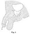
- FIG. 2schematically illustrates female anatomy.
- the urethra 16is the tube that passes urine from the bladder 14 out of the body.
- the narrow, internal opening of the urethra 16 within the bladder 14is the bladder neck 18 . In this region, the bladder's bundled muscular fibers transition into a sphincteric striated muscle called the internal sphincter.
- FIG. 3schematically illustrates male anatomy.
- the urethra 16extends from the bladder neck 18 to the end of the penis 22 .
- the male urethra 16is composed of three portions: the prostatic, bulbar and pendulus portions.
- the prostatic portionis the widest part of the tube, which passes through the prostate gland 24 .
- Incontinencemay occur when the muscles of the urinary system malfunction or are weakened. Other factors, such as trauma to the urethral area, neurological injury, hormonal imbalance or medication side-effects, may also cause or contribute to incontinence. There are five basic types of incontinence: stress incontinence, urge incontinence, mixed incontinence, overflow incontinence and functional incontinence.
- Stress urinary incontinence(SUI) is the involuntary loss of urine that occurs due to sudden increases in intra-abdominal pressure resulting from activities such as coughing, sneezing, lifting, straining, exercise and, in severe cases, even simply changing body position.
- Urge incontinencealso termed “hyperactive bladder” “frequency/urgency syndrome” or “irritable bladder,” occurs when an individual experiences the immediate need to urinate and loses bladder control before reaching the toilet.
- Mixed incontinenceis the most common form of urinary incontinence. Inappropriate bladder contractions and weakened sphincter muscles usually cause this type of incontinence.
- Mixed incontinenceis a combination of the symptoms for both stress and urge incontinence.
- Overflow incontinenceis a constant dripping or leakage of urine caused by an overfilled bladder.
- Functional incontinenceresults when a person has difficulty moving from one place to another. It is generally caused by factors outside the lower urinary tract, such as deficits in physical function and/or cognitive function.
- a variety of treatment optionsare currently available to treat incontinence. Some of these treatment options include external devices, behavioral therapy (such as biofeedback, electrical stimulation, or Kegal exercises), injectable materials, prosthetic devices and/or surgery. Depending on age, medical condition, and personal preference, surgical procedures can be used to completely restore continence.
- behavioral therapysuch as biofeedback, electrical stimulation, or Kegal exercises
- injectable materialssuch
- a sling procedureis a surgical method involving the placement of a sling to stabilize or support the bladder neck or urethra.
- Slings used for pubovaginal proceduresdiffer in the type of material and anchoring methods.
- the slingis placed under the bladder neck and secured via suspension sutures to a point of attachment (e.g. bone) through an abdominal and/or vaginal incision.
- a point of attachmente.g. bone
- Examples of sling proceduresare disclosed in U.S. Pat. Nos. 5,112,344; 5,611,515; 5,842,478; 5,860,425; 5,899,909; 6,039,686, 6,042,534 and 6,110,101.
- the TVT Tension-free Vaginal Tape procedureutilizes a ProleneTM nonabsorbable, polypropylene mesh.
- the meshis a substantially flat, rectangular knitted article.
- the meshincludes a plurality of holes that are sized to allow tissue ingrowth to help avoid infection.
- a plastic sheathsurrounds the mesh and is used to insert the mesh.
- incisionsare made in the abdominal (i.e. suprapubic) area and in the vaginal wall.
- Two curved, needle-like elementsare each connected to an end of the vaginal sling mesh. A sling-free end of one of the needle-like elements is initially pushed through the vaginal incision and into the paraurethral space.
- the needleis angulated laterally (for example, to the right) to perforate the endopelvic fascia, guided through the retropubic space and passed through the abdominal incision.
- the handleis disconnected and the needle is then withdrawn through the abdominal wall, thereby threading a portion of the sling through the tissue of the patient.
- the handleis then connected to the other needle and the technique is repeated on the contralateral side, so that the mesh is looped beneath the bladder neck or urethra.
- the slingis positioned to provide appropriate support to the bladder neck or urethra.
- a Mayo scissors or blunt clampis placed between the urethra and the sling to ensure ample looseness of the sling.
- the cross section of the meshshould be substantially flat. In this condition, the edges of the mesh do not significantly damage tissue.
- the sling endsare then cut at the abdominal wall, the sheath is removed and all incisions are closed.
- the problems associated with improper placement of the TVT meshare particularly troublesome. If the mesh is too loosely associated with its intended physiological environment, the mesh may be ineffective in supporting the urethra and treating incontinence. Several complications can arise from a mesh that is too tightly placed including retention, sling erosion and other damage to surrounding tissue such as the urethra and vagina.
- the meshwill plastically deform and the cross section of the mesh will become arcuate.
- the holes of the TVT meshbecome significantly smaller, and risk deterring tissue ingrowth. Without tissue ingrowth, the potential for infection is believed to increase.
- the edges of the meshtend to curl up and present a relatively sharp, frayed surface. In this curled or deformed state, the edges of the TVT mesh present sharp surfaces that can readily abrade or otherwise damage adjacent tissue such as the urethra, bladder or vagina.
- Attempts to reposition the TVT slingare likely to fail in two modes.
- the surgeonmay apply insufficient elongation force to the mesh (e.g. with forceps), resulting in temporary elastic deformation of the mesh followed by a return by the mesh to its original, unacceptable position after the force is removed.
- the surgeonmay apply excessive force to the mesh resulting in the curling deformation described above with the attendant risk of tissue damage.
- an axially deformed slingnecks down (i.e. decreases in width) and provides less cross sectional area to support the urethra.
- excessive deformation of the TVT slingrisks adversely affecting sling performance.
- some surgeonswill cut the TVT mesh and attempt to remove the mesh as reported in the literature.
- a minimally invasive yet highly effective devicethat can be used with minimal to no side effects.
- Such a deviceshould reduce the complexity of a sling procedure, be biocompatible, adjustable, and non-toxic.
- the treatment methods using the deviceshould reduce pain, operative risks, infections and post operative hospital stays. Further, the method of treatment should also improve the quality of life for patients.
- the present inventioncomprises a surgical device for treating a patient.
- the surgical instrumentis particularly suitable for incontinence procedures.
- the surgical instrumentcomprises at least one needle; at least one atraumatic dilator having a connection means for conveniently and securely connecting the dilator to the needle during a surgical procedure, and a sling material having a length sufficient for the sling material to extend from an abdominal wall of the patient to the urethra of a patient and back to the abdominal wall of a patient, and means for associating the sling with the dilator.
- the dilatoris sized and shaped to afford atraumatic passage through body tissue.
- the dilatoris shorter than the needle to reduce the amount of tissue that is deflected at one time. This contributes to the atraumatic nature of the dilator.
- the dilatorincludes a tapered surface that is shaped to deflect tissue out of the path of the dilator while it is pulled through tissue by the needle.
- the dilatorincludes means for receiving at least a portion of the end of the sling assembly without increasing the profile of the dilator.
- the present inventioncomprises a method of treating urinary incontinence in a patient comprising the steps of creating a pathway in tissue that extends between an abdominal wall of the patient to a pubic space of the patient; dilating the pathways; pulling an implantable support material into the pathways while the pathways are being dilated; and positioning the implantable support material in a therapeutically effective anatomical position relative to tissue of the patient that is intended to be supported.
- the methodcomprises the steps of (a) creating at least one incision in vaginal tissue, (b) creating at least one suprapubic incision, (c) providing an assembly comprising a synthetic implantable material, and a protective sheath situated about the implantable material, the sheath constructed of a material that affords visual examination of the implantable material and that affords passage of the assembly through tissue of the patient, at least one needle that is sized, shaped and designed to either i) initially pass the needle from the vaginal incision to the supra pubic incision, or ii) initially pass the needle from the supra pubic incision to the vaginal incision; and means for associating the needle with the assembly, (d) selecting to either initially pass the needle from the vaginal incision to the supra pubic incision, or to initially pass the needle from the supra-pubic incision to the vaginal incision; (e) passing the assembly through tissue of the patient using the needle according to the selection to locate the implantable material in a therapeutically effective position relative to
- the inventioncomprises a method of implanting a sling to treat urinary incontinence in a female patient comprising the steps of: (i) creating at least one incision in vaginal tissue, (ii) creating at least one suprapubic incision, (iii) initially passing an end of a curved needle guide through the suprapubic incision, (iv) identifying the posterior portion of the patient's pubic bone with the end of the needle to controllably move the end of the needle toward the vaginal incision and to avoid damaging structures such as the urethra and bladder of the patient, (v) passing the end of the needle through the vaginal incision, (vi) associating a sling with the needle, and (vii) implanting the sling in a therapeutically effective position.
- the step of passing the end of the needle through the vaginal incisionincludes the step of placing the surgeon's finger adjacent the patient's endopelvic fascia to locate the end of the needle.
- the step of associating a sling with the needleincludes the step of securely associating the needle with the sling, and the step of implanting the sling includes the step of pulling the needle in a direction away from the vaginal incision toward the suprapubic incision while the sling is securely associated with the needle.
- the step of associating the sling with the needleincludes the step of pushing a dilator along the exterior of the needle from the vaginal incision toward the suprapubic incision, and the step of implanting the sling includes the step of having a sling associated with the dilator so that passage of the dilator along the needle from the vaginal incision toward the suprapubic incision implants the sling.
- the step of associating a sling with the needleoccurs after the step of passing the end of the needle through the vaginal incision.
- the present inventionincludes a method of treating male incontinence.
- the methodincludes steps for implanting a sling material.
- the present inventioncomprises a sling system for use in treating a patient comprising at least one needle having opposing ends; a sling material adapted to be associated with the at least one needle and sized and shaped to extend beneath a patient's urethra up to a patient's abdomen; and a dilator connectable to either of the opposing ends of the at least one needle.
- the present inventioncomprises a surgical needle for implanting a sling of a sling assembly that includes a dilator.
- the needlecomprises an elongate arcuate portion that is sized and shaped to withstand forces encountered during a sling implantation procedure; a first end having attachment means for associating the first end with either a releasably attachable handle or a dilator of the sling assembly, and a second end having attachment means for associating the second end with either a releasably attachable handle or a dilator of the sling assembly.
- the attachment means of the first endincludes surfaces adapted to engage with complementary surfaces on either i) a handle assembly with a releasable, locking feature or ii) a quick, secure connect dilator of the sling assembly.
- the present inventioncomprises a method of implanting a sling to treat urinary incontinence in a patient comprising the steps of (i) creating at least one incision in vaginal tissue, (ii) creating at least one suprapubic incision, (iii) placing a curved needle with a removable handle between the vaginal incision and the suprapubic incision, (iv) then removing the handle, (v) then associating a sling with the needle, and (vi) implanting the sling in a therapeutically effective position.
- the step of associating the sling with the needleincludes the step of pushing a dilator along the exterior of the needle.
- the step of placing a curved needle with a removable handle between the vaginal incision and the suprapubic incisionincludes the step of initially placing the needle in the vaginal incision and moving the needle toward the suprapubic incision.
- the step of placing a curved needle with a removable handle between the vaginal incision and the suprapubic incisionincludes the step of initially placing the needle in the suprapubic incision and moving the needle toward the vaginal incision.
- the present inventioncomprises a sling assembly for use in treating a patient comprising a surgical mesh having a length sufficient to extend from a pubic space of the patient beneath the urethra to an abdomen of the patient on either side of a bladder of the patient; a dilator for passage through tissue of the patient, the dilator being operatively associated with the surgical mesh; and the dilator including surfaces that are sized and shaped to atraumatically deflect tissue during passage of the dilator through tissue.
- the dilatoris adapted to be pulled through tissue by the needle.
- the sling assemblymay include a sheath.
- the present inventioncomprises a surgical kit assembly for treating a patient comprising at least two needles, each of the needles sized and shaped to extend substantially between an abdominal wall and a pubic region of a patient; at least two dilators permanently attachable to the needles; a length of implantable material with a pair of ends, means for associating the ends of the implantable material with the dilators; and at least two handles corresponding to the needles, the handles being releasably attachable to either end of the needles.
- the kitmay optionally include a cystoscopic aid.
- FIG. 1is a side view of a sling according to one aspect of the present invention
- FIG. 1Ais a top view of a sling according to another aspect of the present invention.
- FIG. 2is a schematic view of the female urinary system
- FIG. 3is a schematic view of the male urinary system
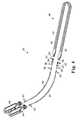
- FIG. 4is a perspective view of one embodiment of the sling delivery system of the present invention, showing the sling delivery system disassembled;
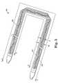
- FIG. 5is a perspective view of one embodiment of a sling assembly of the present invention.
- FIG. 6is an end view showing a vaginal incision and a sling properly located according to an aspect of the present invention
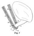
- FIG. 7is a side perspective view of one embodiment of the implanted sling of the present invention.
- FIG. 8Ais a top view of sling showing a side of the sling that is preferably placed facing the urethra;
- FIG. 8Bis a top view of the sling of FIG. 8A, showing the side of the sling opposite the side of the sling shown in FIG. 8A, which side is preferably positioned opposite the urethra;
- FIG. 9Ais a perspective view of an embodiment of sheath according to the present invention.
- FIG. 9Bis a bottom view of a sheath and sling assembly according to the present invention after slight removal of the sheath;
- FIG. 10Ais a perspective view of a dilator according to an aspect of the present invention.
- FIG. 10Bis a top view of the dilator of FIG. 10A;
- FIG. 10Cis a side view of the dilator of FIG. 10A;
- FIG. 10Dis a sectional view of the dilator of FIG. 10A;
- FIG. 10Eis a side view showing a dilator assembled to either a sheath or sling according to aspects of the present invention.
- FIG. 11is a side view of an embodiment of needle, handle and slidable handle according to an aspect of the present invention.
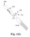
- FIG. 12Ais a perspective view of another embodiment of the dilator of the present invention and portions of a sling assembly or sling in a disassembled condition;
- FIG. 12Bis a perspective view showing the dilator of FIG. 12 A and an insertion needle in a disassembled condition
- FIG. 13is a side view of another embodiment of the dilator of the present invention and portions of a sling or sling assembly, showing the dilator in an unassembled condition;
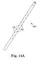
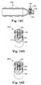
- FIG. 14Ais a perspective view of another embodiment of a dilator/cystoscopy aid of the present invention.
- FIG. 14Bis a sectional view of the dilator/cystoscopic aid of FIG. 14A;
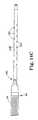
- FIG. 14Cis a side view of a cystoscopic aid/dilator attached to a sling assembly according to the present invention.
- FIG. 15Ais a side view of another embodiment of dilator according to another aspect of the present invention.
- FIG. 15Bis a perspective view of the dilator of FIG. 15A showing the dilator attached to a sling or sling assembly;
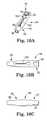
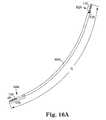
- FIG. 16Ais a side view of a needle of the present invention.
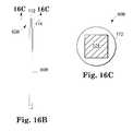
- FIG. 16Bis a side view of a portion of an embodiment of needle according to the present invention.
- FIG. 16Cis a sectional view of a needle according to the present invention; taken approximately along the lines of 16 C— 16 C in FIG. 16B;
- FIG. 16Dis a perspective view of an end portion of a needle according to an aspect of the present invention.
- FIG. 16Eis an end view of a needle in an unseated position
- FIG. 16Fis an end view of a needle in a seated position
- FIG. 17Ais a perspective view of another embodiment of the needle of the present invention.
- FIG. 17Bis a perspective view of another embodiment of needle according to the present invention.
- FIGS. 18A-18Eillustrate one embodiment of the handle of the present invention, wherein:
- FIG. 18Ais a perspective view of the handle
- FIG. 18Bis a sectional view of the handle, showing elements in a disassembled condition
- FIG. 18Cis a sectional view of the handle of FIG. 18A;
- FIG. 18Dis a sectional view of the handle of FIG. 18A showing elements in a locked position
- FIG. 18Eis a perspective view of the handle of FIG. 18A showing elements in an unlocked position
- FIG. 19Ais a perspective view of another embodiment of the handle of the present invention, showing two handles and portions of mating needles,
- FIG. 19Bis a perspective view of another embodiment of handle according to the present invention.
- FIG. 19Cis a perspective view of another embodiment of handle according to the present invention.
- FIG. 20Ais a perspective view of another handle according to the present invention.
- FIG. 20Bis a sectional view of the handle of FIG. 20A;
- FIG. 20Cis an end view of the handle of FIG. 20A;
- FIG. 21Ais a side view of another embodiment of the handle of the present invention.
- FIG. 21Bis another side view of another embodiment of handle according to the present invention.
- FIG. 22Ais a side schematic illustration of one embodiment of a slidable handle and locking mechanism of the present invention.
- FIG. 22Bis a schematic illustration of the slidable handle of FIG. 22A;
- FIG. 23Ais a schematic perspective view of another embodiment of slidable handle and locking mechanism of the present invention.
- FIG. 23Bis a schematic view of portions of the slidable handle and locking mechanism of FIG. 23A;
- FIG. 23Cis a perspective view of a portion of the handle of FIG. 23A;
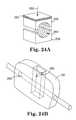
- FIG. 24Ais a perspective view of another embodiment of a slidable handle and locking mechanism of the present invention.
- FIG. 24Bis a schematic perspective view of portions of the handle introduced in FIG. 24A;
- FIG. 24Cis a sectional view of elements of another handle according to the present invention.
- FIG. 24Dis a sectional view of elements of another handle according to the present invention.
- FIG. 24Eis a sectional view of elements of another handle according to the present invention.
- FIG. 25is a schematic perspective view of elements of another handle according to the present invention.
- FIG. 26is a sectional view of another embodiment of a slidable handle and locking mechanism of the present invention.
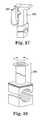
- FIG. 27is a perspective view of another embodiment of a locking mechanism of a slidable handle of the present invention.
- FIG. 28is a perspective view of elements of another embodiment of locking mechanism of a slidable handle of the present invention.
- FIGS. 29A through 29Dare perspective views sequentially showing the insertion of a needle suprapubically according to one aspect of the present invention, wherein:
- FIG. 29Ashows the needle just passing an abdominal incision
- FIG. 29Billustrates the needle as the surgeon seeks to identify the tactile feel of the resistance provided in part by the posterior portion of the pubic bone
- FIG. 29Cshows the needle as it passes along the posterior surface of the pubic bone which may be used as an anatomical guide for a surgeon as the needle approaches a vaginal incision;
- FIG. 29Dillustrates the needle as it passes out of a vaginal incision
- FIG. 30Ais a schematic end view generally illustrating regions to avoid and preferred regions for needle passage in a patient according to an aspect of one embodiment of the present invention
- FIG. 30Bis a schematic end view showing two needles placed in a patient and ready to receive a sling assembly according to another aspect of the present invention.
- FIG. 30Cis a perspective view of a sling system attached to two needles according to a preferred embodiment of the present invention.
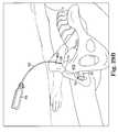
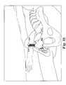
- FIG. 31Ais a perspective view of the sling placed in proximity to the urethra of a patient that shows one method of changing the position of the sling during the surgical procedure, which method is a method of loosening the tension of the sling;
- FIG. 31Bis a perspective view of another method of adjusting the tension of the sling during the surgical procedure according to the present invention, showing a method of tightening the tension of the sling;
- FIG. 31Cis a perspective view the sling according to the present invention after the dilators have been separated from the rest of the assembly, but prior to final trimming;
- FIG. 32is a perspective view of the sling according to the present invention after the sheath has been removed and the sling has been trimmed;
- FIG. 33a schematic perspective view of another embodiment of the method of use of the sling delivery system of the present invention with respect to the male anatomy;
- FIG. 34is a perspective view of another embodiment of surgical procedure according to the present invention showing a needle being initially inserted into the body transvaginally as opposed to suprapubically;
- FIG. 35is an end view of two surgical needles after being inserted in the body transvaginally as shown in FIG. 34, showing handles of the needles on one end of the needles with dashed lines and using an arrow and solid lines to show that the handles are removed and reattached to the needles on the other ends of the needles,
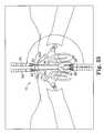
- FIG. 36is a perspective view of the needles of FIG. 35 after a sling assembly has been attached;
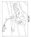
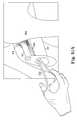
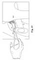
- FIG. 37is a perspective view of another method of adjusting the tension of the sling, showing a method of loosening the tension of the sling either during or even after the surgical procedure;
- FIG. 38is a schematic view of a cadaver
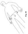
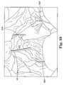
- FIG. 39is a perspective view of the cadaver of FIG. 38 showing proper placement of a prior art needle that was initially inserted transvaginally (on the left) and showing proper placement of a needle according to the present invention that was initially inserted suprapubically (on the right);
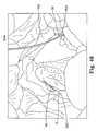
- FIG. 40is a perspective view of a cadaver showing undesirable lateral deviation of the prior art needle that was initially inserted transvaginally (on the left) and showing undesirable lateral deviation of the needle according to the present invention that was initially inserted suprapubically (on the right); and
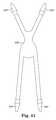
- FIG. 41is a top view of an alternative sling embodiment according to the present invention.
- an embodiment of assembly 40 in accordance with the present inventionincludes a sling assembly 46 that includes a sling 42 for treating incontinence.
- the present inventionis particularly suitable for treating stress urinary incontinence (SUI) diagnosed with urethral hypermobility or intrinsic sphincter deficiency in both men and women.
- SUIstress urinary incontinence
- other urological disorderssuch as urge incontinence, mixed incontinence, overflow incontinence, functional incontinence, prolapse (e.g. vaginal), enteroceles (e.g. of the uterus), rectoceles and other non-urological disorders, are also included within the scope of the present invention.
- prolapsee.g. vaginal
- enterocelese.g. of the uterus
- rectocelese.g. of the uterus
- the present inventionmay also be utilized in conjunction with other procedures, such as, but not limited to, procedures for addressing cystocele prolapse,
- the sling assembly 46preferably includes an implantable member (e.g. a hammock, sling or strip) 42 within a protective sheath 44 .
- the sheath 44is used during insertion of the strip 42 . After the sling 42 is implanted, the sheath 44 is removed and discarded.
- Each of the two ends 48 , 50 of the elongate sling assembly 46attaches to a first end 52 of a dilator 54 or needle-sling connector.
- the dilator 54dilates a needle track for ease of sling introduction and positioning within the patient.
- a second end 56 of each dilator 54is sized and shaped to quickly and securely connect to a first end 58 of a slim, arc-shaped needle 60 .
- An adjustable handle 64is preferably removably and repositionably attached to a second end 62 of the needle 60 .
- Each end 58 , 62 of the needle 60is preferably keyed to allow for convenient, secure attachment of the needle 60 relative to the handle 64 and dilator 54 .
- the key featureprevents rotation of the dilator 54 relative to the needle 60 .
- the handle 64may be rigidly affixed to the needle 60 .
- the sling 42preferably comprises first and second major surfaces, a pair of end portions I, and a support portion II for placement in a therapeutically effective position relative to a physiological environment intended to be supported (e.g. near the urethra).
- the sling 42preferably has a tension adjustment or control member 66 associated with the sling 42 , for transferring sling adjustment forces from one portion of the sling 42 to other portions of the sling 42 such as the ends 61 of a support portion II of the sling (see FIGS. 1 and 1 A).
- the member 66affords effective repositioning of the sling 42 while avoiding undesirable permanent deformation of the sling 42 .
- the tension adjustment memberis a filamentary member.
- the tension adjustment member 66is preferably threaded along the length of sling 42 . More preferably, the tension adjustment member 66 is connected at some points.
- the sling 42comprises a synthetic mesh material
- the filamentmay be affixed at the junctures 61 between the support portion II and the end portions I.
- the sling 42is preferably at least substantially surrounded by the protective sheath 44 , as shown in FIGS. 4 and 5.
- the sling 42 , tension control element 66 and sheath 44are made of biocompatible materials having sufficient strength and structural integrity to withstand the various forces exerted upon these components during an implant procedure and/or following implantation within a patient.
- the protective sheath 44is constructed of a material that affords visual examination of the implantable sling material 42 and that affords convenient passage of the assembly 46 through tissue of the patient.
- the overall dimensions of the sling assembly 46are sufficient to extend from an abdominal incision, to an undersurface of the urethra and back to another abdominal incision with additional size to account for the imprecision associated with the range of human anatomy sizes.
- the sheath length L of the device 40 of the present inventionis approximately within the range of 52.0 cm to 58.5 cm (20.5 inches to 23.0 inches)
- sheath width Wis approximately within the range of 1.0 cm to 1.63 cm (0.482 inch to 0.642 inch)
- sheath material thicknessis approximately within the range of 0.127 mm to 0.203 mm (0.005 inch to 0.008 inch), respectively.
- the associated sling 42has a length X, width Y and thickness approximately within the range of 49 cm to 51 cm (19.3 inches to 20.1 inches), 1.0 cm to 1.2 cm (0.394 inch to 0.472 inch) and 0.508 mm to 0.711 mm (0.020 inch to 0.028 inch), respectively.
- the length of the tension control element 66should be approximately equivalent to or slightly longer than the length of the sling 42 to tighten or loosen the sling 42 after it is placed in the body.
- Alternative lengths, widths and thicknessescan also be used.
- the term “sling”is used generally to include a wide variety of shapes and sizes, materials and treatments. While the sling 42 is preferably rectangular for treating SUI in females, other shapes are also contemplated. Depending on the treatment addressed (e.g. to provide hammock support for the bladder or bladder neck, or to address a rectocele, enterocele or prolapse) the sling may be any of a wide variety of shapes. As an example, the sling may be of the general shape of the slings described and shown in Moir et al., The Gauze - Hammock Operation , Journal of Obstetrics and Gynaecology of the British Commonwealth, Volume 75, No. 1, Pps. 1-9 ( 1968 ). FIG. 41 illustrates another example of a shape of a sling 42 G according to the present invention. This sling shape is believed to be useful for providing a hammock support for an anatomical structure such as the bladder or the juncture between the bladder and bladder neck.
- the sling 42is made of a mesh material.
- the mesh materialcomprises one or more woven or inter-linked filaments or fibers that form multiple fiber junctions throughout the mesh.
- the fiber junctionsmay be formed via weaving, bonding, ultrasonic welding or other junction forming techniques, including combinations thereof.
- the size of the resultant openings or pores of the meshshould be sufficient to allow tissue in-growth and fixation within surrounding tissue.
- the holesmay comprise polygonal shaped holes with diagonals of 0.132 inches and 0.076 inches.
- the quantity and type of fiber junctions, fiber weave, pattern, and material typeinfluence various sling properties or characteristics. Non-mesh sling configurations are also included within the scope of the invention.
- the meshmay be woven polypropylene monofilament, knitted with a warp tricot.
- the stitch countmay be 27.5 courses/inch (+or ⁇ 2 courses) and 13 wales/inch (+or ⁇ 2 wales).
- the thickness of this exampleis 0.024 inches.
- the mesh material of the sling 42comprises a flexible, polypropylene monofilament that resists weakening or degradation when implanted within a patient.
- One such materialis MarlexTM material.
- Other mesh and non-mesh materialsincluding, but not limited to, synthetic biomaterials, allografts, homografts, heterografts, autologous tissues, materials disclosed in U.S. Provisional Applications S/No. 60/263,472, S/No. 60/281,350 and S/No. 60/295,068, whose contents are fully incorporated herein by reference, synthetic materials (such as metallics, polymerics, and plastics) and any combination of such materials may also be used with the device of the present invention.
- synthetic sling materialsinclude, but are not limited to polypropylene, polyethylene, nylon, PLLA and PGA.
- the sling materialshould cause minimal to no reaction with body tissues and fluids and indefinitely retain its particular material characteristics/properties.
- portions or all of the sling 42may be configured or fabricated from a material to either promote or prevent tissue in-growth, or are resorbable to accomplish the desired purpose.
- the sling 42 , sling assembly 46 or portions thereofmay have one or more substances associated therewith through a process such coating.
- appropriate substancesinclude, without limitation, drugs, hormones, antibiotics, antimicrobial substances, dyes, silicone elastomers, polyurethanes, radiopaque filaments or substances, anti-bacterial substances, chemicals or agents, including any combinations thereof.
- the substancesmay be used to enhance treatment effects, reduce potential sling rejection by the body, enhance visualization, indicate proper sling orientation, resist infection or other effects.
- a dyemay be coated on one surface of the sling 42 .
- the dyeprovides the practitioner/surgeon with a visual indicator to aid in properly orienting the sling 42 at the target site within the patient and to avoid undesirable twists along the length of the sling 42 .
- the slingmay be coated by the process described in U.S. Pat. Nos. 5,624,704; 5,756,145; 5,853,745; 5,902,283 and 6,162,487 (the entire contents of which are hereby incorporated by reference).
- the sling 42 of the present inventionneed not have additional sutures or other anchoring devices. Upon implantation, a portion of the sling 42 is passed and/or woven through various layers of abdominal/pelvic tissue. The frictional forces created between the sling 42 and patient tissue prevents movement and loss of tension once the sling 42 is properly located at the target site within the lower abdominal area of the patient. As a result, the sling 42 remains securely in place, even when subjected to various increased abdominal pressures.
- the sling 42is designed to remain within the body of a patient as an implant for a predetermined therapeutically effective amount of time.
- the slingmay be non-absorbable, absorbable or resorbable, including any combinations of these material properties, depending on the desired treatment.
- portions of the sling 42 or sling assembly 46may be constructed of a bioabsorbable material designed to last for a predetermined period of time within the patient, that should be sufficiently long to afford treatment of the patient's need.
- the general characteristics of the sling material and designshould be such as to withstand the various forces exerted upon it during implantation (for example, frictional forces associated with tissue resistance) and after implantation (for example, increased abdominal or bladder pressure caused by coughing, laughing, sneezing, or lifting).
- the sling 42is configured to exploit the healing process and provides adequate support to correct incontinence.
- the sling assembly 46preferably has a feature that assists the surgeon in placing the sling 42 in a therapeutically effective anatomical position.
- the precise, final location of the sling 42will depend on a variety of factors including the particular surgical procedure(s) performed, and any preconditions of the patient such as scar tissue or previous surgeries. For example, it may be preferred to place the sling 42 in close proximity to, but not in contact with, a mid portion of the urethra 16 to treat incontinence. In a male patient, the sling 42 may be placed proximate, but not in contact with the bulbar urethra.
- tension adjustment memberis within the scope of the present invention. Referring to the embodiment shown in FIG. 7, a mesh sling 42 is shown. A tension adjustment member 66 is woven into the sling and attached to the sling 42 via two attachment points 78 located near the midsection 80 of the sling 42 and also corresponding to locations near each side of the urethra 16 .
- the tension adjustment member 66may be a separate element (e.g. threaded along the length of the sling 42 ) or it may be an integral part of the sling matrix.
- the tension adjustment meansmay comprise one filament threaded along the mesh. Alternatively, more than one filament may be used.
- the tension adjustment member 66 shown in FIGS. 1 and 1Ais attached to the mesh at the ends of the middle portion II.
- the tension adjustment meansmay comprise at least one filament that is integrally woven in the mesh and that has extension properties that are different than the other filaments that form the mesh.
- the tension adjustment meansmay be threaded axially along the sling mesh, through the middle of the sling or adjacent its ends. Preferably, this is done at the time of manufacture to provide an assembly that is conveniently used during a surgical procedure, without requiring the surgeon to assemble the sling and tension adjustment means during a surgical procedure.
- the tension adjustment means 66may comprise a plurality non-parallel.
- the elementsmay cross in the support portion II.
- the tension adjustment meansmay comprise a portion of the support portion that is more tightly woven than another portion of the support portion.
- the tension adjustment memberis a continuous, uninterrupted member, as opposed to a member in separate pieces.
- a continuous, uninterrupted memberallows the sling to be tightened and loosened and provides a plurality of locations that can be grasped along the sling 42 to modify the tension of the sling.
- the memberextends the entire length of the sling, from one end to the other.
- a continuous, uninterrupted memberallows the entire sling to be repositioned as opposed to merely isolated portions of the sling.
- the tension adjustment member 66may comprise a monofilament element or a braided member.
- the tension adjustment member 66may be constructed from a biodegradable material or a non-biodegradable material or combinations thereof.
- the monofilamentmay be round, flat or other shapes to aid in fixation or identification.
- the position adjustment member 66enables surgeons to easily tighten or loosen the sling tension during the surgical procedure, even after the surgeon removes the sheath 44 .
- the surgeoncontacts the sling 42 and position adjustment member 66 adjacent the urethra and pulls away from the urethra.
- the tension of the slingmay be increased by grasping the sling 42 and position adjustment member 66 above the abdominal incision and pulling upward.
- One or both ends of the sling 42 and position adjustment member 66may be grasped to increase the tension of the sling 42 .
- Affording adjustment of the sling 42 position after removal of the sheath 44facilitates proper sling placement and helps avoid complications such as retention and sling erosion arising out of improper sling placement.
- the various configurations, properties or characteristics of the position adjustment member 66may vary or remain constant along the length of the position adjustment member 66 .
- the position adjustment member 66may be made of a variety of materials including, but not limited to, ProleneTM, nylon, polypropylene, DekleneTM, poly-L-lactide (PLLA), polyethylene glycol (PGA), polyester and any combination of materials.
- the member 66 or portions thereofmay be absorbable, non-absorbable and/or resorbable. If the member 66 is constructed from an absorbable, bioabsorbable or bioresorbable material or the like, then the member 66 may be optionally left in the sling 42 after the surgical procedure. This offers the advantage of affording the use of the tension adjustment member 66 in a minimally or non-invasive near term, post operation sling tension adjustment procedure.
- FIG. 37illustrates an example of a post operative sling tension adjustment procedure.
- the patientmay be experiencing slight retention shortly after the surgical procedure and the surgeon may wish to slightly loosen the sling 42 .
- the surgeonmay also have the option of placing a blunt instrument 382 into the urethra 16 and slightly deflecting the urethra to thereby loosen the tension of the sling in a lasting fashion.
- this stepwere attempted with prior art slings, the elastic nature of such slings would likely result in temporary, elastic deformation of the sling without a lasting change in the position of the sling.
- the prior art procedurealso risks loss of sling functionality as previously described.
- the individual fibers or filaments comprising the tension adjustment member 66may be extruded, woven, braided, spun, knitted, non-woven or have other similar configurations.
- Member 66 propertiessuch as tensile strength, elongation at break point, stiffness, surface finish, etc., may be similar to or different from those of the sling 42 and may vary along the length of the member 66 .
- the tension adjustment member 66may be secured to the assembly 40 by attaching one or more ends of the tension adjustment member 66 to the sheath 44 .
- the tension adjustment member 66is secured to the device 40 simply by interlacing or weaving the tension adjustment member 66 at predetermined points along the length of the sling 42 .
- the tension adjustment member 66may include one or more points of attachment along the length of the sling 42 .
- the tension adjustment member 66may be attached to the sling assembly 46 via knotting, weaving, bonding, ultrasonic welding or other attachment techniques, including combinations thereof, to prevent tension adjustment member 66 detachment during and/or following sling implantation.
- the tension adjustment member 66is knotted at preselected locations along the length of the sling 42 without any additional elements added to the assembly to connect the member 66 to the sling 42 .
- Knottingallows attachment of the member 66 to the sling 42 without additional securement structure. This embodiment avoids contact between such additional retaining structure and tissue and any attendant complications.
- the knotmay comprise a single throw, half hitch knot, square knot; single overhand knot, a slipknot or a heat formed knot.
- a loop or other shapemay be formed in the member 66 adjacent the end 61 of the support portion II to afford convenience in identifying the end 61 of the support portion II. Such a loop or other shape may be conveniently located and cut should it be desired to remove the portion of the member 66 associated with the support portion II.
- the means 66 for adjusting the tension or anatomical location of the sling 42may optionally comprise a means for indicating proper orientation of the sling 42 .
- the tension adjustment element 66is woven along the length of the sling 42 .
- the tension adjustment element 66is woven more frequently 67 than the less frequent weave 69 of the element 66 in the end portions I of the sling 42 .
- a majority of the element 66is woven above one major side surface of the sling 42 in the support portion. As shown in FIG.
- the major side of the sling with the majority of protruding tension adjustment means 66 Ais located opposite the urethra. If the material of the element 66 A is constructed of a different color, shape or size relative to the material of the sling 42 A, the surgeon may more readily visualize proper placement of the sling 42 A.
- the tension adjustment member 66is woven approximately along the centerline or axial length of the sling 42 .
- the weave pattern of the tension adjustment member 66is used as an indicator of proper sling orientation after implantation.
- the weave pattern on a first major side surface 82 of the sling 42shown in FIG. 8A, has small segments or loops of exposed member 66 .
- the second major side surface 84 (i.e. opposite side 82 or reverse side) of the sling 42shown in FIG. 8B, has larger segments or loops of exposed tension adjustment member 66 .
- the first surface 82 of the sling 42Upon implantation of the sling 42 , the first surface 82 of the sling 42 , having minimal lengths of filament segments or loops protruding above the material of the sling 42 , is preferably positioned to face the urethra 16 of the patient. It is preferred that this first surface 82 of the sling 42 face the urethra 16 to minimize filament 66 -urethra contact, particularly during adjustment of the sling 42 , and to assist the surgeon in identifying the location of the member 66 .
- one or more substancesmay be associated with the member 66 by, for example, a coating process.
- the coatingsmay be selected from the same group mentioned above with respect to coatings for the sling 42 .
- the substancesmay be used to enhance treatment effects, indicate proper sling orientation, enhance tension adjustment member visibility, and resist infection or other effects.
- the tension adjustment member 66may be dyed a contrasting color (e.g. blue) with respect to the sling color (e.g. white). The contrasting color of the tension adjustment member 66 provides the surgeon with a visual indicator that can be used to confirm proper sling orientation.
- other componentsincluding, without limitation, tags, labels or indicia may also be used to indicate proper sling orientation or enhance tension adjustment member 66 visibility/identification.
- FIG. 6illustrates a sling 42 A in a proper position.
- the surgeonmay look through the vaginal incision and view substantially all of the position adjustment member 66 A protruding above a support II (see FIG. 1A) or middle portion of the sling 42 A when the sling 42 A is properly placed. If only a minor portion of the position adjustment member 66 A is visible protruding above a major surface of the sling 42 A, then the sling is misplaced and corrective action should be taken. Once the sling 42 A is located in its final position, the portion of the position adjustment member 66 A in the support portion II of the sling (see FIG.
- the sling 42 Amay include a means for conveniently locating and cutting the tension member 66 A at this point to assist in removal of that portion of the tension member 66 .
- that meansmay comprise a loop or other shape in the tension member 66 .
- a structure attached to the position adjustment member 66my be used to facilitate visualization, maneuverability and cutting of the position adjustment member 66 .
- the sling 42 Amay include a means for grasping the sling 42 A and/or the tension member 66 A in the support portion II of the sling.
- the meansmay comprise a small handle 15 attached to the tension member 66 in the support portion II of the sling 42 A.
- the sling 42 and tension adjustment member 66may be at least partially housed within a sheath 44 .
- the sheath 44is made of a relatively transparent and flexible material having a smooth outer surface. The transparency of the sheath 44 enables a manufacturer or user of the device 40 to view the sling and tension adjustment member 66 encased within the sheath 44 and visually determine whether the sling 42 assembly contains any defects, such as a twisted sling, detached tension adjustment member 66 , torn sling fibers or other related flaws, as well as orientation within the sheath.
- the sheathprovides a protective covering for the sling 42 and tension adjustment member 66 which also resists bacterial and viral contamination of these components.
- the sheath 44is made of polyethylene. Other materials including, without limitation, polypropylene, nylon, polyester or Teflon may also be used to fabricate the sheath 44 .
- the sheath materialshould be flexible and provide sufficient structural integrity to withstand the various forces exerted on the sheath 44 throughout the sling delivery procedure. In general, the sheath 44 is configured to have sufficient flexibility to facilitate user manipulation and adequate structural strength to withstand the various forces applied to the sheath 44 during delivery and/or positioning of the sling assembly 46 . It should also conveniently separate from the sling material 42 after the sling 42 is implanted without materially changing the position of the sling 42 .
- the sheath 44preferably comprises two elongate sections 86 , portions of which detachably and telescopically overlap near the middle portion 80 of the sling (not shown).
- the length S of the overlapping sectionis approximately 3.8 cm (1.5 inch).
- alternative lengthsmay also be used. The length is preferably sufficient to resist exposure of most of the sling 42 and tension adjustment member 66 prior to sheath 44 removal.
- the overlapping sectionmay also be used as a visual indicator for the practitioner or user of the device. In particular, positioning the overlapping portion of the sheath 44 under the bladder neck or urethra 16 ensures proper sling placement (e.g. symmetrical sling placement) and tension within the patient. Additionally, orientation indicia (not shown) may be placed on the overlapping portion to indicate proper orientation of the sling relative to the urethra 16 .
- sheath 44may be unitary as opposed to telescoping with perforations, holes, scores or tear lines designed to allow separation and removal of the sheath 44 .
- the first section 86 and the second section 86 of the sheath 44are slid off the sling 42 by pulling each end of the sheath 44 away from the middle portion 80 of the sling assembly 46 (as shown by reference directional arrows in FIG. 9 B). Removal of the sheath 44 causes separation of the overlapping sheath sections, thereby exposing the sling 42 and tension adjustment member 66 .
- the smooth outer surface of the sheath 44provides a relatively frictionless surface to facilitate passage of the sheath 44 through the various tissues. The relatively frictionless motion also avoids disturbing the position of the sling 42 relative to the anatomy of the patient.
- the sheath 44is associated with one or more substances including those substances identified with respect to the member 66 and sling 42 .
- the substancesmay be used to enhance sheath removal, identify twists along the sheath 44 (and thereby indicate proper sling orientation), indicate cutting/separation points, indicate center-point, resist infection or provide other desirable effects.
- a first surface of the sheath 44may include a colored stripe that should lie opposite the urethra 16 or bladder neck to ensure proper sling orientation.
- the stripeprovides the practitioner/surgeon with a visual indicator to aid in properly orienting the sling assembly 46 , and ultimately the sling 42 , within the patient.
- the ends of the sheathare preferably connected to a dilator.
- the sheathmay be connected to the sling, and the sling can be associated with the dilator.
- the number of dilatorswill depend on factors such as the shape of the sling.
- the sling 42 P shown in FIG. 41includes four dilators 54 P.
- the sling 42 shown in FIG. 4includes two dilators.
- the first end 48 and second end 50 of the sheath 44are preferably configured for attachment to a dilator 54 .
- the dilator 54is a component that atraumatically creates and/or expands the passageway through the tissues for sling assembly delivery.
- the dilator 54includes a means for associating with a needle 60 .
- the dilator 60is preferably short relative to a needle 60 for ease of passage of the assembly and to reduce the overall amount of tissue that is deflected at one time.
- the dilatoris less than 2.5 inches in length, and more preferably, it is less than one inch in length.
- the maximum radius of a dilator 54is preferably less than 10 mm, more preferably less than 7.5 mm, even more preferably less than 5 mm.
- the tip of the dilator 54is preferably blunt, as, in preferred embodiments, the leading tip of the dilator 54 will pass through tissue that has already been pierced by a needle 60 .
- the dilator 54may be made from a variety of biocompatible and sterilizable materials including, without limitation, acetal, Delrin®, Acrylonitrile-Butadiene-Styrene (ABS), polyethylene, nylon and any combination of materials.
- the sheath 44may be additionally or solely connected to an end portion of the sling 42 .
- the dilator 54preferably includes means for associating with a surgical needle 60 .
- the association meansaffords a permanent affixation between the dilator 54 and the needle 60 .
- permanent affixationit is meant that it would be very difficult to manually separate the dilator from the needle after they have become permanently affixed.
- the surgeoncuts an end of the sling 42 as described more fully below.
- the association meanspreferably affords quick and convenient attachment of the dilator 54 to the needle 60 to avoid wasting time in the midst of a surgical procedure. The attachment should also be secure to avoid separation of the needle 60 and dilator 54 while the combination is passed through tissue.
- the dilator 54also includes a means for association with the sling 42 and/or the sheath 44 .
- the dilator 54may be preattached to the sling 42 and/or sheath 44 , particularly if the sling is a synthetic material.
- the dilatormay include means for conveniently attaching to a sling material (e.g. cadaveric or autologous sling material) just prior to sling placement.
- the dilator 54may be approximately 3.1 cm (1.2 inches) in length.
- the dilator 54preferably includes a gentle taper 88 near its second end 56 .
- the dilatoris sized and shaped to provide atraumatic passage through body tissue.
- the taper 88 and relatively smooth outer surface of the dilator 54facilitate atraumatic passage of the dilator 54 and attached sling assembly 46 through the various tissues of the patient.
- the presence of the dilator 54allows a gentle transition between the diameter of the needle, to the shape of the dilator, and finally to the sling assembly 46 , as opposed to prior art assemblies, where the structure of the sling assembly abruptly increases the profile of the needle and thereby the size of the structure that must pass through tissue.
- the first end 52 of the dilator 54attaches to one end of the sling 42 , or sheath 44 or sling assembly 46 (shown in FIG. 10E) and the second end 56 of the dilator 54 may be quickly attached or assembled to a needle 60 (not shown).
- the sheath 44is preferably attached to the dilator 54 via a first opening or through-hole 90 located near the first end of the dilator 54 .
- the opening 90operates as a universal sling material or assembly attachment point which can receive a variety of materials, such as fascia, autologous materials, synthetics, biologic tissues and any other similar tissues, including any combinations.
- the edge portion 91 of one end of the sheath 44is threaded through the opening 90 of the dilator 54 and secured to the sheath 44 , thereby forming a loop 92 .
- the edge portion 91may be fastened onto the sheath 44 via ultrasonic welding, bonding, melting, suturing, sealing or other attachment techniques.
- the first end 52 of the dilator 54includes a cut-away section 94 to provide room to receive sling assembly material to reduce the overall profile of the sling assembly experienced by tissue during sling passage. Therefore, when the sheath is attached to the cut-away section, the additional sheath material is not apt to significantly increase the relative thickness, diameter or profile of the dilator 54 .
- the end of the sheath 44may be encased within and secured to the first end 52 of the dilator 54 during the molding process.
- the end of the sheath 44may be fixedly attached within a longitudinal slot located near the first end 52 of the dilator 44 using an adhesive, ultrasonic welding or other attachment techniques.
- the second end 56 of the dilator 54includes a second opening or through-hole 96 that extends substantially internally along the longitudinal axis of the dilator 54 .
- the second opening 96has an internal diameter generally configured for convenient attachment to a needle 60 or similar sling-delivery device.
- the internal diameter of the second opening 96 of the dilator 54is approximately within the range of 0.239 cm to 0.318 cm (0.094 inch to 0.125 inch).
- a shoulder 98 located on the surface 100 of the second opening 96 of the dilator 54 and a complementary mating recess located on the surface of the first end of the needle 60 (see FIG. 4)securely and permanently attach or lock the dilator 54 and needle 60 together.
- the needle 60is inserted into the dilator 54 , they are preferably not separated thereafter.
- the connected needle 60 and dilator 54are removed from the sling by cutting an end of the sling as described in greater detail below.
- the needle 60 and dilator 54are disposed.
- One or more longitudinal slots 102 located on the outer surface of the dilator 54 and in communication with the second opening 96allow the wall of the dilator 54 to expand in a radially outward direction when the first end of the needle 60 is inserted into the second opening 96 of the dilator 54 .
- the shoulder 98 of the dilator 54passes the recess of the needle 60
- the wall of the dilator 54collapses around the needle 60 as the shoulder 98 seats into the recess, thereby securing the dilator 54 on the needle 60 and blocking separation of the dilator 54 and needle 60 .
- the dilator 54preferably includes one or more relief ports 104 to facilitate convenient needle connection.
- the relief ports 104may be formed at the ends of the longitudinal slots 102 or at various high-resistance locations along the dilator 54 .
- the relief ports 104decrease the rigidity or resistance of radially outward expansion of the dilator wall and, reduce the amount of force required to insert or securely attach the needle 60 to the dilator 54 .
- superficial bands or rings, arc-shaped slots, superficial grooves or other mechanismsmay be provided to provide improved expansion or attachment characteristics.
- a portion of the dilator 54includes a taper 88 having a decreasing profile toward the second end 96 of the dilator 54 .
- the taper 88preferably gently cams tissue out of the path of the sling assembly 46 as the sling assembly is inserted in the body.
- the taper 88is also sized and shaped to reduce the amount of friction or resistance as the device is drawn through the tissues of the patient. The amount of force required to manipulate the device through the tissues is thereby reduced. This in turn provides the user of the assembly with additional control over device insertion and maneuverability through tissue and within the patient.
- dilator profilessuch as conical, flared, frusto-conical, pyramid-shaped, elliptical or other applicable profiles may also be used.
- the profile of the dilator 54is preferably configured to provide easy dilation of the tissue to accommodate smooth passage of the sling 42 /sling assembly 46 and subsequent collapse of the surrounding tissue to securely anchor the sling 42 into the tissue (after sheath removal).
- the dilator 54 A or 54 Bincludes a sling fastening snap mechanism 106 on one end of the dilator.
- the embodiment disclosed in FIG. 12Aincludes a keyed/locking mechanism on its other end.
- the first end of the dilator 54 Aincludes a slot or slot-shaped opening 110 configured for convenient insertion of one end of a sling 42 (such as one made from autologous tissue) or sling assembly 46 either at the surgical site (e.g. by the operating room nurse or surgeon) or other location (such as manufacturing location). Additional shapes for the dilator opening 110 include, without limitation, oval, circular, square, rectangular and other shapes.
- the slot-shaped opening 110is located along a portion of the longitudinal axis of the dilator 54 A.
- a snap-like element 112 ′is located on an outer surface near the first end of the dilator 54 B.
- the snap-like element 112 ′includes a barb or spike 114 that fits within an opening 116 situated near the first end of the dilator 54 B.
- the opening 116 for the barb 114preferably configured perpendicular to the slot-shaped opening 110 ′, is sized and shaped to match or mate with the barb 114 of the snap-like element 112 ′.
- a first ridge 120 and a second ridge 122 located along the length of the barb 114further secure and/or fasten the barb 114 within the opening 116 of the dilator 54 B.
- Other fastening configurationsincluding, but not limited to, bumps, shoulders, tabs, detents, tongue in grooves, snaps and any combinations of fastening means may also be used with the present invention.
- one end of the sling 42 , sheath 44 or sling assembly 46is inserted into the slot 110 ′ of the dilator 54 B.
- the barb 114 of the snap-like element 112 ′is inserted into the opening 116 of the dilator 54 B.
- the barb 114is fully seated within the opening 116 when both ridges 120 , 122 pass through the opening 116 of the dilator 54 B.
- a keyed/locking mechanism 108is located near the second end 56 B of the dilator 54 B.
- a square-shaped opening 124extends along a portion of the longitudinal axis near the second end 56 B of the dilator 54 B.
- the shape of the dilator opening 124matches the square-shaped perimeter of the keying-segment 126 located near the first end 58 of the needle 60 and allows keyed-rotation of the dilator 54 B at ninety-degree intervals.
- Other appropriate shapes for the dilator opening 124may also be used provided that the shape of the opening 124 complements the corresponding keying-segment shape located near the first end 58 of the needle 60 .
- the square-shaped opening 124 of the dilator 54 B together with the keying-segment 126 of the needle 60prevents axial rotation of the dilator 54 B relative to the needle 60 and, thus, twisting of the sling 42 /sling assembly 46 .
- This optional featureprovides the practitioner or user of the assembly with improved control and maneuverability of the assembly before and during the insertion procedure.
- the dilator 54 Balso includes a locking mechanism 128 .
- the locking mechanism 128comprises one or more tension-loaded ribs located within the longitudinal opening of the dilator 54 B.
- the configuration of the ribsgenerally matches and corresponds to a complementary recess 130 located near the first end 58 of the needle 60 .
- the first end 58 of the needle 60is inserted through the longitudinal opening 124 of the dilator 54 B until the ribs of the dilator 54 B seat within the recess 130 of the needle 60 .
- the dilator 54 Bis securely attached or locked onto the needle 60 when the dilator ribs are fully seated within the needle recess 130 .
- the sheath 44(or sling 42 or assembly 46 ) is attached to the dilator 54 C via a locking (or compression) collet 132 and adapter connector 134 .
- the compression collet 132comprises a ring-shaped portion 136 having one or more barbed snap tongs 138 .
- the complementary adapter 134comprises a cylindrical element 140 having a first end 142 and a second end 144 .
- the internal profile near the first end 144 of the adapter connector 134includes a tubular lumen or channel 146 , having one or more recesses, shoulders, grooves or similar indentations 148 , surrounding an internal prong 150 .
- the second end 144 of the adapter connector 134includes one or more barbed snap tongs 152 , similar to the tongs 138 of the compression collet 132 .
- the first end 52 of the dilator 54 Cincludes a longitudinal opening 154 having one or more recesses, grooves, slots or related types of indentations 156 configured to engage the tongs 152 of the adapter connector 134 .
- one end of the sling 42 /sling assembly 46 of the present inventionis configured into a tubular or appropriate shape that enables a sufficient portion of the end of the sling 42 /sling assembly 46 to be inserted through the compression collet 132 .
- the tongs 138 of the compression collet 132are then inserted into the first end 142 of the adapter connector 134 , causing the tongs 138 to snap into engagement with the adapter connector 134 .
- the end portion of the sling 42 /sling assembly 46is compressed between the tongs 138 of the compression collet 132 and the internal prong 150 of the adapter connector 134 , thereby securely fixing the sling 42 /sling assembly 46 to the collet/adapter assembly.
- the tongs 152 of the adapter 134are then inserted and snap-locked into the first end 52 C of the dilator 54 C, creating a secure fixation between the collet/adapter assembly and dilator 54 C.
- the length of the dilator 54 Dis substantially equivalent to the length of the needle 60 used for the sling delivery procedure.
- the dilator 54 Dcomprises a hollow, ataumatic trocar-shaped component generally made of a soft, semi-flexible material, such as high density polyethylene, polypropylene, polyvinyl chloride (PVC), polytetrafluoroethylene (PTFE) or other similar materials, including combinations thereof.
- PVCpolyvinyl chloride
- PTFEpolytetrafluoroethylene
- the material and design of the dilator 54 Dallows the dilator to be positioned over or passed along the length of the needle 60 , thereby totally or partially encasing the needle 60 , similar to an Amplatz sheath/dilator.
- this embodiment of the dilator 54 Dwill be hereafter referenced as the cystoscopy aid 54 D.
- tongue and groove structuremay be supplied in the needle 60 and cystoscopic aid 54 D to guide the cystoscopic aid 54 D along the needle 60 .
- the hollow portion or internal lumen 158 of the cystoscopy aid 54 Dmay be sized and shaped to accommodate passage of a dilator 54 and/or sling 42 and/or sling assembly 46 , similar to those previously described.
- the cystoscopy aids 54 Dare positioned over the needles 60 , the dilators 54 and/or sling 42 and/or sling assembly 46 are connected onto the ends of the needles 60 .
- the needles 60 and attached componentsare then pulled through the internal lumen 158 of the cystoscopy aids 54 D until the sling 42 is positioned adjacent the target site or urethra 16 and the needles 60 connected components are withdrawn from the patient.
- the cystoscopy aids 54 Dare then removed from the patient, allowing the tissue to gently collapse around the sling 42 .
- This configuration of the deviceallows components such as dilator 54 , sling assembly and subsequent needle maneuvering to be performed substantially within the hollow portion 158 of the cystoscopy aid 54 D, thereby reducing potential tissue trauma and infection.
- one or more apertures or perforations 160that function to facilitate verification of bladder and urethra integrity, are disposed along the length of the cystoscopy aid 54 D.
- the cystoscopy aid 54 Dmay be pushed along the exterior surface of each needle 60 . If the bladder has been punctured during needle insertion causing urine leakage or drainage within the patient, the urine or bladder fluid will enter the apertures 160 of the cystoscopy aid 54 D and flow along the surface and out from the needle 60 . This allows the practitioner to quickly and easily confirm urethra and bladder integrity.
- a first end 162 of the cystoscopy aid 54 Eis attached to an end of a sling 42 , or sling assembly 46 or portions thereof.
- the sling 42 /sling assembly 46may be attached to the cystoscopy aid 54 E using attachment mechanisms and techniques similar to those previously described throughout this disclosure.
- cystoscopy aid 54 Eis pushed along the exterior of a needle 60 to maneuver and properly position the sling 42 /sling assembly 46 in a therapeutic position relative to anatomical structures such as the urethra or bladder.
- the cystoscopy aid 54 E or dilator 54may include a hollow portion configured to house the sling assembly 46 .
- the sling 42 /sling assembly 46would be folded, rolled or similarly configured for placement inside the hollow portion of the dilator or cystoscopy aid 54 E.
- One role of the dilator 54 E or cystoscopy aid 54 E in this embodiment, similar to that of the sheath 44is to reduce friction or tissue trauma as the sling 42 is drawn through the various tissues. It is noted that the sheath 44 is a wholly optional element of the present invention.
- the embodiment of the present invention shown in FIG. 14Cis believed to potentially reduce sling assembly component contamination/exposure and wound infection.
- a set of grasping jaws 164may incorporate a dilator, as shown in FIGS. 15A and 15B.
- the jaws 164are constructed from a bioabsorbable material.
- a first end 166 of the jaws 174attaches to the needle 60 via a snap or quick fitting attachment.
- a second end 168 of the jaws 164attaches or clamps onto the sling 42 or sling assembly 46 .
- the jaws 164may serve to anchor the sling 42 within tissue of a patient.
- the mechanism by which the jaws 164 attach to and release the sling 42 or sling assembly 46may be similar to that of a bioptome. Other exemplary mechanisms such as a ball-detent used on a ratchet wrench, spring loaded clamps, memory alloys, and other mechanisms may also be used.
- the jaws 164may optionally be operably connected to and controlled by the handle 64 of the device. Manipulation of the handle 64 causes the jaws 164 to open and close, thereby enabling the device to clamp onto and/or release the sling 42 or sling assembly 46 .
- the handle 64may be further manipulated to detach the jaws 164 or a portion thereof from the needle 60 . As such, once the sling 42 or sling assembly 46 is properly located within the patient (further described below), the bioresorbable jaws 164 are detached from the needle 60 either inside or outside the body of the patient.
- the needle 60is generally curved or arcuate.
- the needleis arc-shaped and includes a first end 58 and a second end 62 .
- a variety of needle designs and/or configurationsmay be used including, without limitation, straight, bent, curved, arc-shaped, Stamey, Raz and other configurations, all references hereinafter will be made to an arc-shaped needle in the spirit of brevity and reader convenience.
- the shape of the needle 60should facilitate and provide controlled passage of the needle 60 through tissue, preferably from an abdominal incision to the vagina or, alternatively, from the vagina to an abdominal incision.
- the ends or tip of the needle 60are preferably not sharpened, but may be tapered to afford easy passage through tissue while providing a blunt surface that avoids cutting sensitive tissue such as the bladder or urethra.
- the length N of the needle 60is approximately within the range of 16.5 cm to 24.1 cm (6.5 inches to 9.5 inches) and has a preferred external diameter of approximately 3.175 mm (0.125 inch). It is preferred that the diameter of the needle 60 be small relative to the prior art to reduce tissue trauma.
- the needle 60is made of a malleable, yet durable, biocompatable surgical instrument materials such as, but not limited to, stainless steel, titanium, Nitinol, polymers, plastics and other materials, including combinations of materials.
- the needle 60should have sufficient structural integrity to withstand the various forces (e.g. forces caused by dilator attachment, cystoscopy aid passage, and penetration/passage of the needle 60 through the various tissues) without undergoing any significant structural deformation.
- the needles 60could be sufficiently malleable to allow a practitioner or user of the device to modify the needle 60 to a desired shape and, thereby, optimize the procedural approach.
- the first end 58 and second end 62 of the needle 60may include a keying feature 170 affording secure association between the needle and handle 64 and/or dilator 54 and/or sheath assembly 46 .
- the keying feature 170comprises a recess 130 and/or square-shaped portion 126 .
- the recess 130 and square-shaped portion 126are designed for complementary engagement to the appropriate end of a dilator 54 or handle 64 .
- Another embodiment of the inventionincludes a reversible keying feature. The reversible keying feature allows the handle 64 to be interchangeably attached yet securely affixed to either end of the needle 60 .
- the needle 60may be substantially symmetric about a centerpoint, that is, the radius of curvature of the needle 60 may be substantially constant and either a handle or a dilator may be attached to either end of the needle 60 .
- the keying feature of the needle 60 Bcomprises an end cap 172 and an elongate reduced width segment 174 having a square-shaped cross sectional profile, as shown in FIGS. 16B to 16 D.
- the second end 62 B of the needle 60 shown in these Figuresis inserted into the keying feature or channel 176 that extends along the longitudinal axis of the handle 64 B (partially shown in FIGS. 16D to 16 F).
- a yoke or other fastening component 178receives and secures the elongate segment 174 in the narrow portion 180 of the channel 176 , as shown in FIGS. 16D and 16E.
- the complementary configuration of the channel's narrow portion 180 and the needle's elongate segment 174prevents the handle 64 B from rotating around the axis of the needle 60 B.
- this configurationmay also provide additional needle/handle stability and improved tactile feedback for a user of the device.
- the present inventionmay optionally include structure that allows the surgeon to change the orientation or position of the handle relative to the needle.
- the handlemay be rotatably repositioned relative to the needle or, in some embodiments, the handle may be axially slidable and repositionable along the length of the needle.
- the handlemay be repositioned in any orientation as determined by the surgeon or it may be indexed between a plurality of predetermined orientations depending on the particular embodiment of the present invention.
- FIG. 16Eillustrates the needle seated in a locked position relative to handle 64 B.
- a user or practitionermanipulates a trigger or button that actuates the fastening component 178 thereby causing the channel 176 to disengage from the elongate segment 174 , as shown in FIG. 16 F.
- segment 174 of the needle 60 Bis no longer seated in the handle 64 B.
- the needle 60 Bis free to rotate.
- the configuration of the needle's end cap 172prevents the needle 60 B from becoming completely disengaged from the handle 64 B.
- the keying featuresmaintain the needle 60 B in proper alignment with the handle 64 B when in the locked position and also allow a user to controllably rotate the needle 60 B to obtain a desired handle 64 B orientation.
- the needle 60 Ccomprises an assembly 184 having one or more detachable components.
- the needle assembly 184comprises a body portion 186 and one or more segments 188 .
- An external thread 189 formed near the end of the body portion 186allows needle segments 188 , dilators 54 , slings 42 , or sling assembly 46 to be screwed onto the body portion 188 thereby forming the needle assembly 184 .
- the devicesmay be easily removed by simply unscrewing them from the body portion 186 of the needle assembly 184 .
- Other configurations or designs of the needle assembly 184may include, but are not limited to, hollow or solid body portions 186 , snap fit, memory alloy or latching mechanisms, internal threading or other designs.
- the handle 64may be permanently attached to an end 62 of the needle 60 . More particularly, the handle 64 may be rigidly affixed to the needle 60 so that substantially no relative movement may occur between the needle 60 and the handle 64 .
- one embodiment of the adjustable handle 64 Gcomprises a relatively smooth, ergonomic body made of delrin, ABS, nylon, polycarbonate, acetal, polyetherimide, polysulfone or other sterilizable materials.
- the body of the handle 64 Gmay be hollow, solid or semi-solid.
- One or more surfaces of the handleinclude a plurality of ridges 190 and/or indentations 192 that provide an enhanced gripping surface for a user of the device.
- various portions of the surface of the handle 64 Gmay also include grasping features such as bumps, grooves, ridges or other gripping means, that enable improved manipulation of the handle 64 G.
- the handle 64 Gmay include an indentation formed near the middle 194 of the handle 64 G that provides a user of the device with better control of, and an improved grip on, the handle 64 G.
- a push button 198 and keyed opening 200are located near the needle attachment end 196 of the handle 64 G shown in FIG. 18 A and form a keying feature of the handle 64 G.
- the push button assembly 198comprises a button or knob-shaped component 202 that attaches to a yoke 204 (attachment locations indicated by dashed reference line).
- the yoke 204is attached to the button 202 via snap tongs 206 that lock the button 202 and yoke 204 together.
- the button 202 and yoke 204including a spring 208 , are fitted within their respective grooves and/or slots formed near the needle attachment end 196 of the handle 64 G, as generally shown in FIG. 18 C.
- the spring 208provides the appropriate tension to maintain the assembly in a locked position.
- FIG. 18 DWhen the assembly is in a locked position (shown in FIG. 18 D), the spring forces push the button 202 in a direction away from the longitudinal axis of the device. This in turn causes the groove or recess 210 of the attached yoke 204 to protrude within the keyed longitudinal opening 200 resulting in a non-square-shaped opening formed along an axial portion near the needle attachment end of the handle 64 G.
- the handle 64 Gis securely attached in a stationary position on the needle 60 . Pressing or pushing the button 202 inwardly toward the axis of the device unlocks the device and creates a square-shaped or keyed opening 200 for the needle 60 .
- FIG. 18Eillustrates a cross-section of the keyed, longitudinal opening 200 in an unlocked position.
- the quick-release push button of the handle 64 Genables a user of the device to easily attach or detach the handle 64 G from the needle 60 or reposition the orientation of handle 64 G relative to the needle 60 , using one hand. While gripping the handle 64 G, the user of the device simply depresses the push button 202 with one finger to unlock the handle. Still using a single hand to control the handle 64 G, the user can then insert one end of the needle 60 into the keyed opening 200 of the handle 64 G and, upon releasing the button 202 , secure the handle 64 G to the needle 60 .
- the needle 60includes a similar keying feature configured for complementary engagement with the keyed portion of the handle 64 G.
- These complementary, square-shaped keying featuresallow a practitioner or user of the device to rotatably index the handle 64 G between predetermined positions located in ninety-degree increments around the needle axis. Thus, the practitioner may position the handle 64 G in a preferred configuration on the needle 60 that provides the greatest comfort and ease of insertion.
- the keying featuresalso prevent the handle 64 G from uncontrollably rotating around the axis of the needle 60 , for instance, during a sling or needle insertion procedure.
- FIGS. 19A to 19 CAnother embodiment of needle attachment mechanism for a handle is shown in FIGS. 19A to 19 C.
- the handle 64 Hincludes a quick-release feature 212 comprising one or more levers 214 and an associated border or frame 216 that surrounds an opening 218 .
- the opening 218is generally located near the needle end of the handle 64 and along the longitudinal axis of the device.
- the frame 216 bordering the opening 218may include various indentations or ridges 220 that provide improved gripping capabilities.
- the handlemay also include a square-shaped keying feature 222 similar to the previously described keying features.
- a different shaped handle 64 Iis shown in FIGS. 19B and 19C.
- a practitioner or user of the devicesimply compresses the levers 214 of the handle 64 H together using, for example, a thumb and forefinger. Compression of the levers 214 changes the configuration of the frame 216 and opening 218 to allow insertion of a needle 60 therein.
- the user of the devicereleases the levers 214 when the needle 60 is properly positioned within the handle 64 I, causing a portion of the frame 216 to compress against a portion of the needle 60 (e.g., a recessed portion) thereby blocking axial movement of the needle relative to the handle 64 I and securely attaching the handle 64 I onto the needle 60 .
- the handle 64 Ican be quickly released from the needle 60 by pressing on the handles 214 .
- FIGS. 20A-20CAnother embodiment of a quick-release feature for the handle 64 K is shown in FIGS. 20A-20C.
- the handle 64 Kmay be made from a single molded or machined component.
- a quick-release button 224located near the needle end of the handle 64 K, controls a keyed needle-latching mechanism 226 .
- the needle latching mechanism 226generally includes a geometrically shaped opening section 228 , a locking section 230 and an end section 232 .
- the semi-resilient material of the handle 64 Kcauses displacement of the locking section 230 , thereby allowing the needle 60 (not shown) to be inserted into the latching mechanism 226 of the handle 64 K.
- the button 224is released causing the locking section 230 to return to its initial configuration and, in so doing, seat within the complementary, recessed feature of the needle 60 . This not only secures or locks the handle 64 K onto the needle 60 but also prevents the handle 64 K from rotating around the needle axis.
- the keyed, locking portion and/or quick release feature of the handle 64 Kmay be located near the middle of the handle 64 K, near the end of the handle 64 K close to the needle (FIG. 18A) or at any preferred location on the handle 64 K.
- a large or small section or length of the needle 60may be housed within and contact the handle 64 K of the device, thereby providing enhanced user-control and stabilization of the needle 60 relative to handle 64 K.
- the increased surface contact between the needle 60 and handle 64 Kmay also strengthen the associated gripping or frictional forces, resulting in improved locking or attachment capabilities of the device.
- the associated quick-release feature(such as push button 198 , button 224 , levers 214 , etc.) may also be positioned at any preferred location on the handle 64 of the present invention. For example, referring to FIGS. 21A and 21B, positioning the button 202 opposite to the needle insertion end 196 of the handle 64 L may reduce or prevent accidental triggering of the button 202 . Further, this particular design may provide additional ergonomic advantages for the user of the device. For example, the bottom could be flush or recessed with the surface of the handle.
- FIGS. 21A and 21Banother embodiment of the handle 64 L comprises a compact profile.
- the smaller size of the handle 64 Lreduces the weight of the handle 64 L, thereby making the device 40 less heavy at the top and better balanced.
- the handle 64 Lmay also be configured to be permanently, but rotatably, affixed to the needle 60 (not shown). As such, the user or practitioner may rotate the handle 360° around the axis of the needle 60 and lock the handle 64 L in position once the desired orientation is reached.
- FIG. 11illustrates an alternate embodiment of the present invention that includes a slidable second handle 64 ′ which may be used alone or in combination with handle 64 .
- the slidable handlemay provide additional ergonomic advantages and control during the needle insertion procedure.
- the slidable handle 64 ′when used in combination with the handle 64 , the slidable handle 64 ′ is initially positioned and optionally locked near the first end 58 of the needle 60 .
- the slidable handleallows the user or practitioner to maneuver the needle 60 more accurately along the insertion pathway.
- the slidable handle 64 ′is unlocked and repositioned closer to the handle 64 .
- the slidable handleis then secured at the new position and locked in place, thereby allowing further insertion of the needle 60 .
- the second handle 64 ′may optionally be locked in a position that blocks inadvertent lurching of the needle 60 within the tissue.
- the second handle 64 ′is sized and shaped to engage the abdominal tissue to act as a stop to prevent further penetration of the needle 60 until the second handle 64 ′ is unlocked and moved to a location closer to the handle 64 .
- This featureis believed to be useful in resisting uncontrolled passage of the needle 60 into the retropubic space after the end 58 of the needle 60 bursts through the tough rectus fascia. Once the rectus fascia is penetrated, the second handle 64 ′ is unlocked and moved to a location closer to the handle 64 and the needle can be controllable passed through tissue.
- the second handle 64 ′may include means for affording sliding of the handle 64 ′ toward the handle 64 , but that resists movement of the handle 64 ′ away from the handle 64 .
- the meansmay comprise a plurality of ribs within handle 64 ′ that engage the needle 60 and that are angled toward the handle 64 .
- a slidable handle 204comprises a body portion 206 (partially shown in FIGS. 22 A and 22 B), latch 208 , o-ring 210 and spring ring 212 contained in a handle cavity 207 .
- the body portion 206 and latch 208may be made of delrin, ABS, nylon, polycarbonate, acetal, polyetherimide, polysulfone, or other sterilizable materials.
- the o-ring 210 and spring ring 212may be made from high durometer polyurethane, teflon and other rigid or semi-rigid materials.
- the frustro-concially shaped spring ring 212comprises a first end 214 , a second end 216 and a lumen 218 .
- the external diameter of the first end 214 of the spring ring 212is greater than the external diameter near the second end 216 of the spring ring 212 , thereby forming an inclined surface.
- the lumen 218situated along the axis of the spring ring 212 , is configured to slidably engage a needle 60 .
- the o-ring 210comprises a first end 220 , a second end 222 and a lumen 224 having a first surface 226 and a second surface 228 .
- the first surface 226 of the lumen 224is located near the first end 220 of the o-ring 210 and forms an incline configured for complimentary engagement with the inclined surface of the spring ring 212 .
- the second surface 228 of the lumen 224is located near the second end 222 of the o-ring 210 and is designed to slidably engage the needle 60 .
- a latch 208Adjacent to the o-ring 210 is a latch 208 comprising two posts 230 and two tabs 232 , wherein similar ends of each post 230 are attached to a tab 232 .
- the posts 230border the needle 60 in perpendicular alignment with the needle axis, thereby forming, together with the tabs 232 , a frame around a portion of the needle 60 .
- One end 234 of each post 230also includes a flange 236 that triggers the locking mechanism of the handle 204 .
- the handle 204is locked onto a needle 60 by depressing a tab 232 so that the flange 236 contacts a portion of the o-ring 210 and causes the o-ring 210 to engage the spring ring 212 .
- a projection 238may be formed on an external surface of the o-ring 210 and configured for complimentary engagement with an indentation 240 formed on an internal surface of the handle 204 . Further, the handle 204 may be unlocked in a similar fashion by simply depressing the other tab 208 and, thereby, releasing the compressive forces which causes the components to disengage.
- FIG. 22Billustrates an embodiment of lockable handle similar to that of FIG. 22 A. Elements in FIG. 22B have been given reference characters similar to those of FIG. 22A, to which the suffix “B” has been added.
- an alternate embodiment of the slidable handlecomprises a body portion, o-ring 212 , spring ring 210 and slider 242 contained in a handle cavity.
- the o-ring 210 and spring ring 212 of this embodiment of the slidable handle 204are similar to those previously described.
- the cylindrically shaped o-ring 210includes at least one rod 244 extending perpendicular to the needle axis and partially projecting from the cylindrical surface of the o-ring 210 .
- the slider 242 of the handle 204comprises two shafts 246 , that pivot on a rod (not shown) about a pivot point 248 , and a switch 250 .
- the shafts 246 , switch 250 and rod 244may be made from substantially the same materials, such as delrin, ABS, nylon, polycarbonate, acetal, polyetherimide, polysulfone or other similar materials.
- the first end 252 and second end 254 of each shaftare configured to securely engage the switch 250 and rod 244 , respectively, thereby forming the slider assembly.
- the slider 242 in combination with the o-ring 219 and spring ring 212are the mechanisms by which the needle 60 and handle 204 may be locked and unlocked.
- a userlocks the handle 204 by pushing or pressing the switch 250 in one direction. This action causes the shafts 246 to move the o-ring 210 into complementary engagement with the spring ring 212 . As previously described, the resulting frictional forces prevent linear displacement of the needle 60 , thereby securely locking the handle 204 onto the needle 60 .
- the handle 204may be unlocked by simply pushing the switch 250 in the opposite direction.
- the slidable handlecomprises a body portion 206 , upper block 256 , lower block 258 , load distributor 260 and force providing member 262 (e.g. a cam).
- the body portion 206 of the handle 204may be made of materials similar to those described in previous embodiments.
- the lower and upper blocks 258 , 256may be made of high-density polyurethane, whereas the load distributor 260 and force providing member 262 may be made of a material with a high coefficient of friction.
- the generally square-shaped blocks 256 , 258include a channel 264 formed within a portion of each block.
- the channels 264are configured to house a needle 60 when the blocks 256 , 258 are properly aligned within the handle body 206 .
- ridges, bumps, or other similar gripping featuresare formed on the surface of each channel 264 to enhance the needle gripping capabilities of the blocks 256 , 258 .
- the handle of FIGS. 24A-24Elocks onto a needle 60 by depressing the force providing member 262 .
- the force providing member 262forces the upper block 256 into close proximity with the lower block 258 , subsequently compressing or sandwiching the needle 60 therebetween.
- the compression forceswhich are evenly displaced via the load distributor 260 , together with the gripping surfaces of the blocks 256 , 258 prevent linear displacement of the needle 60 relative to the handle when locked within the handle body 206 , as shown in FIG. 24 D.
- the gripping featuresshould sufficiently prevent the handle body 206 from rotating about the needle axis, additional keying features may also be added.
- the needle 60 and needle lumen 268 of the handle body 206may include complementary features, such as flattened surfaces 270 shown in FIG. 24E, that provide added stability to the present invention.
- an alternate embodiment of the locking mechanism of the slidable handle 204comprises an upper clamping block 272 , lower block (not shown), two cams 276 , a rod 278 and two pins 280 .
- the needleis designed to be placed between the upper and lower blocks and sandwiched therebetween. Rotation of the wheel cams 276 provide balanced pressure on clamping block 272 .
- the slidable handle 204comprises a body portion 206 and locking mechanism 282 .
- the body portionmay be made from silicone rubber or other elastomeric materials.
- the body portion 206includes a barbed inner lumen 284 that functions as the locking mechanism for the needle 60 (not shown).
- the orientation of the barbsprevent the slidable handle 204 from sliding in one direction along the needle 60 (e.g. toward the end of the needle that is placed in the tissue), yet permit the handle 204 to slide in the opposite direction along the needle 60 .
- FIG. 27Another embodiment of the locking mechanism is shown in FIG. 27 .
- This mechanismis similar to the embodiment of the locking mechanism referenced in FIGS. 24A-24E. However, instead of depressing a cam 262 , a user depresses a button 286 that latches into a mating release element 288 .
- Yet another embodiment of a locking mechanism, shown in FIG. 28,comprises a screw-like device 290 that can be locked and unlocked simply by twisting or rotating a portion of the device 290 .
- Other embodiments of locking mechanismsare also included within the scope of the claimed invention.
- the present inventioncomprises a kit for treating a patient (e.g. for SUI).
- the kitpreferably comprises at least two needles, an implantable material for supporting structure and at least two dilators.
- Two or more needlesreduces the need to reuse a needle at a different location with a patient, thereby eliminating cross contamination issues.
- Additional needles, dilators and other elementsmay also be included for surgical convenience, for avoidance of contamination from one portion of the body to another, for ease of manufacturing or sterilization or for surgical requirements.
- four needlesmay be utilized to implant the sling of FIG. 41 . The needles would pass through abdominal incisions and through a vaginal incision.
- the sling 42may includes a means for determining the tension in the sling.
- the tension determination meansmay comprise an element attached to the sling or incorporated in the sling that is capable of measuring sling tension.
- the elements of the assembly of the present inventionmay be any color.
- the elementsare of constructed to be a color that contrasts with the intended physiological environment and with other elements.
- the sling 42is preferably white and the position adjustment member 66 may be blue. This helps the surgeon identify the location and discern the elements of the assembly.
- FIGS. 29A through 30Ca preferred embodiment of surgical procedure for treating female incontinence is disclosed according to an aspect of the present invention.
- the patientis placed under local, spinal or general anesthesia.
- a small transverse incision 404is made in the anterior vaginal wall 20 of a female patient followed by a transurethral dissection.
- Two small transverse suprapubic abdominal stab incisions 400are also made near the back of the pubic bone (e.g. each about 1 cm from the midline, or alternatively, one large incision may be made) to allow for needle entry.
- two paraurethral dissections (incisions next to the urethra) lateral to the midlinemay be created to allow the surgeon's finger to meet the end 58 of the needle 60 during the procedure.
- a handle 64is optionally adjusted relative to needle 60 according to surgeon preference and securely associated with the second end 62 of the needle 60 .
- the attachment and configuration of the needle-handle assemblymay be adjusted or customized to user preference.
- the handle 64may be optionally released from the needle 60 by pushing a button or compressing levers located on the handle 64 . Once released, the handle 64 can then be rotated or displaced along an axis of the needle 60 to a preferred position. After the handle 64 is properly positioned on the needle 60 , the button or levers are released, thereby causing the handle 64 to become securely attached to the needle 60 .
- FIG. 29Ashows the second end 58 of needle 60 just passing an abdominal incision 400 .
- the surgeonsseeks to encounter resistance associated with the posterior portion of the patient's pubic bone 402 with the second end 58 of the needle 60 to controllably move the end 58 of the needle toward the vaginal incision 404 and to help avoid damaging structures such as the urethra and bladder of the patient.
- the second end 58 of the needle 60is used to identify the location of the pubic bone 402 .
- the surgeonexploits the resistance provided by the pubic bone 402 to controllably pass the end of the needle 58 . This approach is preferred as it helps keep the needle 60 away from major pelvic vessels, nerves and anatomical structures such as the urethra, bowels and bladder.
- FIG. 29Billustrates the end of the needle as it just passes the suprapubic incision.
- FIG. 29Cillustrates the needle 60 as the surgeon experiences the tactile feel of the resistance provided in part by the posterior portion of the pubic bone 402 .
- FIG. 29Cshows the needle 60 as it passes in proximity to the posterior surface of the pubic bone 402 which continues to operate as an anatomical guide for the surgeon as the needle end 58 approaches vaginal incision 404 (see FIG. 29 D).
- FIG. 30Ais a schematic end view generally illustrating regions to avoid 390 during the surgical procedure and preferred passage region 385 . Deviation of the end 58 of the needle 60 outside of the preferred passage region 385 into the regions to avoid 390 is believed to increase the potential for damaging arteries, veins, organs, lymph tissue and other tissues that are likely to lead to complications. Passing the needle 60 in the preferred passage region 385 avoids contact between the end of the needle 58 and these structures.
- FIG. 29Dillustrates the needle as it passes out of a vaginal incision 404 .
- the surgeontypically holds the handle 64 of the needle 60 during this time by using predominantly one hand.
- the surgeonmay meet the end 58 of the needle via the paraurethral dissection.
- the surgeon's fingermay be delicately placed adjacent endopelvic fascia of the patient and used to guide the needle 60 through the relatively tough endopelvic fascia and into the vaginal incision 404 . This helps the surgeon keep away from structures such as the bladder, urethra and other sensitive tissue.
- the small diameter and curvature of the needles 60help to provide precise passage of the needles 60 to the vaginal incision 404 .
- this needle configurationcreates a minimally invasive pathway through tissue extending between the abdominal wall and pubic space, thereby reducing the risk of perforating the bowel and/or blood vessels and nerves located lateral to the bladder 14 .
- FIG. 30Bis a schematic end view showing two needles placed in a patient and ready to receive a sling or sling assembly. Once both needles are placed, surgeons typically perform a cystoscopy to ensure that the bladder is not punctured before implanting the sling. A cystoscopy confirms the integrity of the bladder 14 and urethra 16 or recognizes a bladder perforation.
- the plastic cystoscopy aid shown in FIG. 14 Amay optionally be used for this purpose. The cystoscopy aid may be used separately or in conjunction with cystoscopy.
- FIG. 30Cis a perspective view of a sling system associated with two needles 60 .
- the plastic sheath 44is oriented so that the optional center orientation indicia (e.g. a blue mark) is facing away from the surgical field, toward the surgeon.
- the dilators 54are then pushed onto the ends 58 of needles 60 as shown in FIG. 30 C.
- the dilators 54are preferably snapped irreversibly into place for a secure connection.
- the dilators 54are connected to the needle in a fashion that prevents rotation of the dilators 54 relative to the needles 60 .
- the dilatorneed not be directly connected to the needles 60 and, instead, a flexible dilator with a lumen (e.g. dilator 54 E shown in FIG. 14C) may be pushed along the exterior portion of the needle 60 in order to implant a sling.
- a flexible dilator with a lumene.g. dilator 54 E shown in FIG. 14C
- the dilator of this embodimentis pushed in a direction from the vaginal incision 404 toward the suprapubic incision 400 , but the opposite direction is also contemplated as within the present invention.
- the surgeondetermines that the majority of any optional adjusting filament 66 is facing away from the urethra 16 (see FIG. 6 ), and that the sling mesh is untwisted.
- Dilators 54including a pre-attached sling assembly 46 , are attached to the first ends 58 of the needles 60 protruding from the vagina 20 .
- the sling assembly 46is properly oriented so that the sling assembly 46 is not twisted prior to attaching the second dilator 54 to the end of the other needle 60 .
- the sling assembly 46is oriented so that the larger filament loops (of the position adjustment member 66 ) are facing outward or away from the urethra 16 .
- the needlesare pulled up through the suprapubic incisions as shown by the arrows in FIG. 30C, taking care to avoid contact with sensitive tissue.
- the slingis then clamped with surgical clamps (not shown).
- the handles 64are used to pull the needles 60 up through the suprapubic incisions 400 .
- the attached dilators 54 and sling assembly 46are atraumatically pulled up through the needle paths, advancing the sling assembly 46 adjacent to and looped beneath the urethra 16 or target site. A portion of each end of the sling assembly 46 extending beyond the suprapubic incisions 400 is clamped and then cut to release the needles 60 and attached dilators 54 .
- the slingis placed in a therapeutically effective position.
- the precise anatomical positionwill depend upon a variety of factors including the type and degree of anatomical damage or insufficiency, whether the sling procedure is combined with other procedures and other surgeon decisions.
- the slingis placed midurethra, without tension, but in position to support the midurethra.
- the slingcould be placed to support the bladder neck and/or UV junction.
- the overlapping portion of the sheath 44 located near the center of the sling assembly 46 and the axially located member 66may then be used to center and properly position the sling assembly 46 under the midurethra.
- the sheath 44is then removed.
- FIG. 31Ais a perspective view of the sling placed in proximity to the urethra of a patient that shows one method of permanently adjusting the position or “tension” of the sling during the surgical procedure.
- the surgeonpulls down or away from the urethra on the sling 42 and position adjustment member 66 using a blunt instrument 372 to shift the sling away from the urethra 16 , thereby reducing tension.
- the blunt instrumente.g. a clamp
- the position adjusting member 66transfers some of the force placed on the sling 42 by the blunt instrument 372 to another location on the sling (e.g. the end 61 of the support portion II of the sling 42 shown in FIG. 1 A). This action is believed to be effective in permanently reducing the tension of the sling 42 and increasing the space between the sling 42 and the urethra 16 , even after the sheath 44 is removed.
- the position adjustment member 66is a continuous member that extends the length of the support portion II (FIG. 1A) of the sling 42 and avoids contact with the vaginal incision 404 .
- a member 66 that is separated at the mid portion of the slingwould be difficult to engage with member 372 .
- a sling with a continuous, non-separated position adjustment member 66is particularly helpful, as the surgeon is working at a remote location in cramped quarters. Additionally, a position adjustment member that hung down into the vaginal incision 404 may cause complications due to interaction with the incision 404 .
- the position adjustment member 66 laterally located on both sides of the urethra 16may be cut (e.g. at the ends 61 of the support portion II) and removed. Alternatively, the position adjustment member 66 may be left in place, particularly if it consists of a degradable material or is an integral part of the sling 42 .
- the sling 42is also trimmed adjacent to the suprapubic incisions 400 , thereby removing the excess sling material extending outside the body of the patient.
- the position adjustment member 66extends substantially along the entire length of the sling 42 (see FIGS. 1 and 1A) so that the member 66 can be used to increase the tension of the sling (e.g. position the sling closer to the urethra).
- FIG. 31Bis a perspective view of another method of adjusting the position or “tension” of the sling during the surgical procedure. Sling tension may be tightened by placing a device, such as a clamp, across one or both ends of the sling 42 , suprapubically. The entire sling width and the associated member 66 should also be captured within the clamp. In addition, the sling 42 may be rolled or looped around the clamp to improve the grip.
- the end of the sling 42is then pulled in an upward direction to tighten the sling 42 as desired.
- the tension adjustment member 66transfers some of the force provided by the clamp to another location of the sling (e.g. the ends 61 of the support portion II) to more effectively reposition the sling 42 . If necessary, this tightening procedure can also be repeated on the other end of the sling 42 located on the contra lateral side.
- a member 66 that does not extend substantially along the entire length of the sling 42could not be used to increase the tension of the sling.
- FIG. 31Cshows the sling after the dilators have been cut off, but prior to final trimming.
- the position adjustment member 66may be cut lateral to the urethra on both sides (e.g. at 61 in FIG. 1) and it is removed prior to the end of the surgical procedure. Optionally, it may be left in place after the surgical procedure.
- the sling 42is finally cut to size at the suprapubic incisions 400 as shown in FIG. 32 . After the procedure, the surgeon closes the suprapubic and vaginal incisions.
- a Foley cathetermay be used to facilitate voiding at the surgeon's discretion.
- the surgeonverifies the proper placement of the sling 42 as the sling mesh may be difficult to move after the plastic sheath 44 is removed.
- the plastic sheath 44is removed from the sling mesh 42 by pulling up on both sides of the sheath 44 , preferably one at a time, and preferably in the direction of the arrows of FIG. 31 C.
- a forceps or other blunt instrumentmay be placed between the sling and the urethra.
- the member 66is not cut and remains attached to the sling 42 . Maintaining filament 66 attachment to the sling 42 affords convenient postoperative adjustments to sling tension. Further, with respect to the embodiment of the invention whereby the member 66 is coated with a radiopaque substance, retaining the member 66 allows the practitioner to track post-operative changes to the position of the sling 42 and/or urethra 16 .
- FIG. 37is a perspective view of another method of permanently repositioning or adjusting the “tension” of the sling.
- the surgeonplaces a blunt device in the urethra 16 and pulls down, thereby permanently loosening the tension of the sling 42 . This may help avoid the need to reposition the sling by dissecting the vagina 20 and grasping the sling.
- the vaginamay be dissected and the member 66 or sling 42 directly accessed through another vaginal incision.
- a small incisionis made in the perineal area 406 of a male patient.
- two small transverse suprapubic incisions 400are also made to allow for needle entry.
- the handle 64is securely attached and properly positioned on the needle 60
- the first end of the needle 60is passed through one of the suprapubic incisions 400 , down the posterior side of the pubic bone 402 , through the endopelvic fascia and into the perineal incision 406 .
- the user of the deviceutilizes the handle 64 to guide the needle 60 through the various tissues, avoiding major pubic vessels, the bladder 14 and prostate gland.
- the second needle 60is inserted in a similar fashion on the contra-lateral side.
- a cystoscopy proceduremay be performed to confirm bladder integrity.
- the dilators 54 and sling assembly 46are then positioned under the target site, sling tension is adjusted and the remainder of the procedure is performed similar to that previously described for a female patient.
- cystoscopy aids 54 Dcan be used in addition to, or optionally in place of the cystoscopy procedure. Once both needles 60 are in place, the cystoscopy aids 54 D are passed along the length of the needles 60 . If the bladder has been punctured during needle insertion causing urine leakage within the patient, the urine enters the apertures 160 of the cystoscopy aids 54 D, flows along the surface and out from the needle 60 .
- the cystoscopy aids 54 Dmay be removed, the sling 42 or sling assembly 46 may be attached to the cystoscopy aids 54 D or the sling 42 /sling assembly 46 may be hidden within or pulled through the cystoscopy aids 54 D.
- the cystoscopic aidsare a contrasting color (e.g. blue) to afford ready identification of blood or other leakage from the bladder or other structures.
- the slidable handle 204is used in place of or in combination with the handle 64 .
- the slidable handle 204is positioned in a locked configuration near the first end 58 of the needle 60 and handle 64 is positioned near the second end 62 the needle 60 .
- the repositionable handle 204may be used as a stop to prevent inadvertent lurching of the needle 58 into sensitive tissue.
- the user or practitionerpushes the needle 60 through the incision 400 using handle 64 and guides or maneuvers the needle 60 through the various tissues and spaces using slidable handle 204 .
- the userWhen the slidable handle 204 comes in close proximity to the incision, the user unlocks the handle 204 and slides the handle 204 along a length of the needle 60 . The slidable handle 204 is thereby repositioned away from the incision and closer to the first end 62 of the needle 60 . Once properly located, the slidable handle 204 is then locked in place and the insertion procedure continues. The unlocking, repositioning and locking actions are repeated at the convenience and discretion of the surgeon until the needle 60 is fully inserted.
- this embodimentprovides a system with more controlled and precise maneuverability than prior art structures.
- one end of the needle 60is initially passed through a vaginal incision 404 and toward one of the suprapubic incisions 400 . While inserting the needles 60 initially through the vagina is not preferred, it is within the scope of the present invention as some surgeons may prefer this approach due to previous surgical training, custom or personal preference.
- the handles 64are used to push and precisely guide the needle 60 through the various tissues, without perforating or damaging the bowel and/or blood vessels.
- a second needle 60may be inserted in the same way on a contra-lateral side. As before, a separate cystoscopy procedure may be performed to confirm bladder integrity.
- the handles 64are detached from one end of the needles 60 and securely attached at the opposite ends of the needles 60 protruding from the abdominal incision 400 .
- a user of the devicecan use the same handles 64 to also withdraw the needles 60 from the patient.
- the first pair of handles 64can be detached from the needles 60 protruding from the vagina and discarded.
- a second pair of new or different handles 64can then be attached to the needles 60 protruding from the abdominal incision 400 and used for the remainder of the procedure.
- the dilators 54 and sling assembly 46are attached to the ends of the needles 60 protruding from the vagina 20 .
- the remainder of the procedureis similar to that described in previous embodiments of the invention.
- FIG. 38is a schematic view of a cadaver.
- FIG. 39is an illustration of an opened cadaver showing, on the left, a prior art TVT needle VA that was properly placed using an initial vaginal approach; and on the right, a needle SPA properly placed according to a preferred embodiment of the present invention (using a suprapubic approach).
- the TVT procedurerequires the surgeon to blindly pass a large diameter stainless steel trocar upward in a retrograde, retropubic fashion through the retropubic space to position a sling beneath the urethra.
- the upward approachlacks anatomical guides to assist in positioning the needle in a path that is spaced from pelvic vessels, nerves, organs and sensitive tissue such as the urethra, bladder and bowel.
- FIG. 40is another view of the cadaver showing the TVT needle VA laterally deviated from its proper path and the needle SPA laterally deviated from its proper path. Because the vaginally inserted TVT needle VA is blindly passed upward through the retropubic space, it is believed that the end E of the needle VA is more prone to injure pelvic vessels and nerves 502 or even the bladder or bowel. In contrast, even if the end 58 of the needle SPA inserted according to a preferred embodiment of the present invention deviates slightly laterally as shown in FIG. 40, the surgeon may exploit the resistance provided by the posterior portion of the pelvic bone 402 to correct the path of the needle SPA back into the preferred passage region 385 (FIG. 30A) and avoid the pelvic vessels and nerves 504 . This also helps reduce the risk of puncturing sensitive tissue such as that of the bladder, bowels and urethra.
- the device of the present inventioncan also be used for male patients.
- a perineal approachmay be used for male patients.
- One end of a needle 60is initially passed through a perineal incision 406 and toward one of the suprapubic incisions 400 .
- the insertion of the second needle 60 and the remainder of the procedureare similar to that previously described.
- sheath tags, center markers or other meansmay be used to aid the practitioner in accurately centering the sheath 44 under the urethra or bladder neck in females or bulbar urethra in males.
- end and/or center markingsmay be used as additional aids for separating the delivery system from the sling 42 and centrally placing the sling 42 at the target site.
- four needlesmay be utilized to implant the sling shown in FIG. 41 .
- the needlesmay extend from four abdominal incisions to a vaginal incision.
- the sling 42 Pmay be used as a hammock to support the bladder or for other procedures to address a cystocele or prolapse or a vaginal vault treatment.
Landscapes
- Health & Medical Sciences (AREA)
- Life Sciences & Earth Sciences (AREA)
- Surgery (AREA)
- General Health & Medical Sciences (AREA)
- Public Health (AREA)
- Biomedical Technology (AREA)
- Heart & Thoracic Surgery (AREA)
- Veterinary Medicine (AREA)
- Engineering & Computer Science (AREA)
- Animal Behavior & Ethology (AREA)
- Molecular Biology (AREA)
- Nuclear Medicine, Radiotherapy & Molecular Imaging (AREA)
- Medical Informatics (AREA)
- Urology & Nephrology (AREA)
- Cardiology (AREA)
- Oral & Maxillofacial Surgery (AREA)
- Transplantation (AREA)
- Vascular Medicine (AREA)
- Rheumatology (AREA)
- Pathology (AREA)
- Prostheses (AREA)
- Surgical Instruments (AREA)
- Infusion, Injection, And Reservoir Apparatuses (AREA)
Abstract
Description
Claims (1)
Priority Applications (52)
| Application Number | Priority Date | Filing Date | Title |
|---|---|---|---|
| US09/917,443US6612977B2 (en) | 2001-01-23 | 2001-07-27 | Sling delivery system and method of use |
| US10/005,837US20020147382A1 (en) | 2001-01-23 | 2001-11-09 | Surgical articles and methods |
| US09/990,108US6641525B2 (en) | 2001-01-23 | 2001-11-21 | Sling assembly with secure and convenient attachment |
| ES01985603TES2230381T3 (en) | 2001-01-23 | 2001-12-28 | ASSEMBLY WITH SAFE AND PRACTICAL FIXING SUPPORT HANDLE. |
| DE60115498TDE60115498T2 (en) | 2001-01-23 | 2001-12-28 | SURGICAL ARTICLES |
| KR1020037009693AKR100797490B1 (en) | 2001-01-23 | 2001-12-28 | Surgical Sling Transfer System |
| EP01985603AEP1353597B1 (en) | 2001-01-23 | 2001-12-28 | Sling assembly with secure and convenient attachment |
| CA002404459ACA2404459C (en) | 2001-01-23 | 2001-12-28 | Surgical sling delivery system |
| PCT/US2001/049642WO2002058564A2 (en) | 2001-01-23 | 2001-12-28 | Surgical articles |
| ES01988357TES2247188T3 (en) | 2001-01-23 | 2001-12-28 | SURGICAL SUPPORT HANDLE DELIVERY SYSTEM. |
| EP04019832AEP1508305A3 (en) | 2001-01-23 | 2001-12-28 | Assembly for treating incontinence |
| CA002434461ACA2434461C (en) | 2001-01-23 | 2001-12-28 | Sling assembly with secure and convenient attachment |
| PCT/US2001/049632WO2002058563A1 (en) | 2001-01-23 | 2001-12-28 | Implantable sling |
| PCT/US2001/049581WO2002062237A1 (en) | 2001-01-23 | 2001-12-28 | Surgical sling delivery system |
| AU2002241673AAU2002241673B2 (en) | 2001-01-23 | 2001-12-28 | Surgical sling delivery system |
| ES01991458TES2249490T3 (en) | 2001-01-23 | 2001-12-28 | SURGICAL ITEMS. |
| AU2002235239AAU2002235239B2 (en) | 2001-01-23 | 2001-12-28 | Sling assembly with secure and convenient attachment |
| JP2002562246AJP4133330B2 (en) | 2001-01-23 | 2001-12-28 | Sling delivery system |
| AT01991458TATE311148T1 (en) | 2001-01-23 | 2001-12-28 | SURGICAL DEVICES |
| CA002403687ACA2403687C (en) | 2001-01-23 | 2001-12-28 | Surgical articles |
| AU2002231181AAU2002231181B2 (en) | 2001-01-23 | 2001-12-28 | Implantable sling |
| PCT/US2001/049578WO2002058562A1 (en) | 2001-01-23 | 2001-12-28 | Sling assembly with secure and convenient attachment |
| AT01991456TATE375756T1 (en) | 2001-01-23 | 2001-12-28 | IMPLANTABLE SLING |
| AT01988357TATE308928T1 (en) | 2001-01-23 | 2001-12-28 | SYSTEM FOR INSERTING A SURGICAL SNOSE |
| CA002502394ACA2502394C (en) | 2001-01-23 | 2001-12-28 | Surgical articles |
| DE60105200TDE60105200T2 (en) | 2001-01-23 | 2001-12-28 | SUITABLE FOR A SAFE AND FAVORABLE LOCKING DEVICE |
| EP01991458AEP1353599B1 (en) | 2001-01-23 | 2001-12-28 | Surgical articles |
| EP01991456AEP1353598B1 (en) | 2001-01-23 | 2001-12-28 | Implantable sling |
| DE60131020TDE60131020T2 (en) | 2001-01-23 | 2001-12-28 | IMPLANTABLE SLING |
| AT01985603TATE274329T1 (en) | 2001-01-23 | 2001-12-28 | SNRING DEVICE SUITABLE FOR SAFE AND EFFECTIVE ATTACHMENT |
| BRPI0116812-6ABR0116812B1 (en) | 2001-01-23 | 2001-12-28 | surgical device for treating a patient. |
| DE60114882TDE60114882T2 (en) | 2001-01-23 | 2001-12-28 | SYSTEM FOR THE INTRODUCTION OF A SURGICAL SLING |
| EP01988357AEP1353601B1 (en) | 2001-01-23 | 2001-12-28 | Surgical sling delivery system |
| CA2434463ACA2434463C (en) | 2001-01-23 | 2001-12-28 | Implantable sling |
| AU2002231182AAU2002231182B2 (en) | 2001-01-23 | 2001-12-28 | Surgical articles |
| US10/280,341US6971986B2 (en) | 2001-01-23 | 2002-10-25 | Sling delivery system and method of use |
| US10/280,945US7048682B2 (en) | 2001-01-23 | 2002-10-25 | Surgical articles and methods |
| US10/423,662US7407480B2 (en) | 2001-07-27 | 2003-04-25 | Method and apparatus for correction of urinary and gynecological pathologies, including treatment of incontinence cystocele |
| US10/616,925US7083568B2 (en) | 2001-01-23 | 2003-07-11 | Implantable article for treatment of urinary incontinence |
| US10/616,938US7112171B2 (en) | 2001-01-23 | 2003-07-11 | Sling assembly with secure and convenient attachment |
| US10/675,816US7291104B2 (en) | 2001-01-23 | 2003-09-30 | Surgical articles and methods |
| US11/202,315US8864646B2 (en) | 2001-01-23 | 2005-08-12 | Surgical articles and methods |
| US11/203,136US7867161B2 (en) | 2001-01-23 | 2005-08-15 | Sling delivery system and method of use |
| US11/535,018US7972262B2 (en) | 2001-01-23 | 2006-09-25 | Sling assembly with secure and convenient attachment |
| US11/981,597US8702585B2 (en) | 2001-07-27 | 2007-10-31 | Pelvic health implants and methods |
| US11/983,430US8777836B2 (en) | 2001-07-27 | 2007-11-07 | Pelvic health implants and methods |
| US12/984,422US8475357B2 (en) | 2001-01-23 | 2011-01-04 | Sling delivery system and method of use |
| US13/115,311US8784295B2 (en) | 2001-01-23 | 2011-05-25 | Sling assembly with secure and convenient attachment |
| US13/903,474US8852077B2 (en) | 2001-01-23 | 2013-05-28 | Sling delivery system and method of use |
| US14/257,475US10206771B2 (en) | 2001-07-27 | 2014-04-21 | Pelvic health implants and methods |
| US14/497,892US9554884B2 (en) | 2001-01-23 | 2014-09-26 | Surgical articles and methods |
| US15/384,946US10555798B2 (en) | 2001-01-23 | 2016-12-20 | Surgical articles and methods |
Applications Claiming Priority (7)
| Application Number | Priority Date | Filing Date | Title |
|---|---|---|---|
| US26347201P | 2001-01-23 | 2001-01-23 | |
| US26982901P | 2001-02-20 | 2001-02-20 | |
| US28135001P | 2001-04-04 | 2001-04-04 | |
| US29506801P | 2001-06-01 | 2001-06-01 | |
| US30691501P | 2001-07-20 | 2001-07-20 | |
| US09/917,443US6612977B2 (en) | 2001-01-23 | 2001-07-27 | Sling delivery system and method of use |
| US10/280,341US6971986B2 (en) | 2001-01-23 | 2002-10-25 | Sling delivery system and method of use |
Related Parent Applications (3)
| Application Number | Title | Priority Date | Filing Date |
|---|---|---|---|
| US09/917,562Continuation-In-PartUS6652450B2 (en) | 2001-01-23 | 2001-07-27 | Implantable article and method for treating urinary incontinence using means for repositioning the implantable article |
| US10/005,837Continuation-In-PartUS20020147382A1 (en) | 2001-01-23 | 2001-11-09 | Surgical articles and methods |
| US10/280,341Continuation-In-PartUS6971986B2 (en) | 2001-01-23 | 2002-10-25 | Sling delivery system and method of use |
Related Child Applications (6)
| Application Number | Title | Priority Date | Filing Date |
|---|---|---|---|
| US09/917,562Continuation-In-PartUS6652450B2 (en) | 2001-01-23 | 2001-07-27 | Implantable article and method for treating urinary incontinence using means for repositioning the implantable article |
| US10/005,837Continuation-In-PartUS20020147382A1 (en) | 2001-01-23 | 2001-11-09 | Surgical articles and methods |
| US09/990,108Continuation-In-PartUS6641525B2 (en) | 2001-01-23 | 2001-11-21 | Sling assembly with secure and convenient attachment |
| US10/280,341ContinuationUS6971986B2 (en) | 2001-01-23 | 2002-10-25 | Sling delivery system and method of use |
| US10/280,341Continuation-In-PartUS6971986B2 (en) | 2001-01-23 | 2002-10-25 | Sling delivery system and method of use |
| US10/423,662Continuation-In-PartUS7407480B2 (en) | 2001-07-27 | 2003-04-25 | Method and apparatus for correction of urinary and gynecological pathologies, including treatment of incontinence cystocele |
Publications (2)
| Publication Number | Publication Date |
|---|---|
| US20020099258A1 US20020099258A1 (en) | 2002-07-25 |
| US6612977B2true US6612977B2 (en) | 2003-09-02 |
Family
ID=27559440
Family Applications (6)
| Application Number | Title | Priority Date | Filing Date |
|---|---|---|---|
| US09/917,443Expired - LifetimeUS6612977B2 (en) | 2001-01-23 | 2001-07-27 | Sling delivery system and method of use |
| US10/280,341Expired - LifetimeUS6971986B2 (en) | 2001-01-23 | 2002-10-25 | Sling delivery system and method of use |
| US10/616,925Expired - LifetimeUS7083568B2 (en) | 2001-01-23 | 2003-07-11 | Implantable article for treatment of urinary incontinence |
| US11/203,136Expired - Fee RelatedUS7867161B2 (en) | 2001-01-23 | 2005-08-15 | Sling delivery system and method of use |
| US12/984,422Expired - Fee RelatedUS8475357B2 (en) | 2001-01-23 | 2011-01-04 | Sling delivery system and method of use |
| US13/903,474Expired - Fee RelatedUS8852077B2 (en) | 2001-01-23 | 2013-05-28 | Sling delivery system and method of use |
Family Applications After (5)
| Application Number | Title | Priority Date | Filing Date |
|---|---|---|---|
| US10/280,341Expired - LifetimeUS6971986B2 (en) | 2001-01-23 | 2002-10-25 | Sling delivery system and method of use |
| US10/616,925Expired - LifetimeUS7083568B2 (en) | 2001-01-23 | 2003-07-11 | Implantable article for treatment of urinary incontinence |
| US11/203,136Expired - Fee RelatedUS7867161B2 (en) | 2001-01-23 | 2005-08-15 | Sling delivery system and method of use |
| US12/984,422Expired - Fee RelatedUS8475357B2 (en) | 2001-01-23 | 2011-01-04 | Sling delivery system and method of use |
| US13/903,474Expired - Fee RelatedUS8852077B2 (en) | 2001-01-23 | 2013-05-28 | Sling delivery system and method of use |
Country Status (11)
| Country | Link |
|---|---|
| US (6) | US6612977B2 (en) |
| EP (2) | EP1353598B1 (en) |
| JP (1) | JP4133330B2 (en) |
| KR (1) | KR100797490B1 (en) |
| AT (2) | ATE375756T1 (en) |
| AU (2) | AU2002241673B2 (en) |
| BR (1) | BR0116812B1 (en) |
| CA (2) | CA2404459C (en) |
| DE (2) | DE60114882T2 (en) |
| ES (1) | ES2247188T3 (en) |
| WO (2) | WO2002058563A1 (en) |
Cited By (232)
| Publication number | Priority date | Publication date | Assignee | Title |
|---|---|---|---|---|
| US20020188169A1 (en)* | 1999-06-09 | 2002-12-12 | Kammerer Gene W. | Surgical instrument and method for treating female urinary incontinence |
| US20030023138A1 (en)* | 1999-06-09 | 2003-01-30 | Luscombe Brian H. | Surgical instrument and method for treating female urinary incontinence |
| US20030149440A1 (en)* | 1999-06-09 | 2003-08-07 | Ethicon, Inc. | Surgical instrument and method for treating female urinary incontinence |
| US20030176762A1 (en)* | 2000-03-09 | 2003-09-18 | Kammerer Gene W. | Surgical instrument and method for treating organ prolapse conditions |
| US20030195386A1 (en)* | 2000-09-07 | 2003-10-16 | Thierfelder Christopher A. | Implantable article and method |
| US20030216814A1 (en)* | 2002-05-07 | 2003-11-20 | Siegel Steven W. | Male urethral prosthesis with tensioning member |
| US20030220538A1 (en)* | 2002-03-01 | 2003-11-27 | Bernard Jacquetin | Method and apparatus for treating pelvic organ prolapses in female patients |
| US20040006353A1 (en)* | 2002-04-30 | 2004-01-08 | Bosley Rodney W. | Sling for supporting tissue |
| US20040097974A1 (en)* | 2002-08-29 | 2004-05-20 | Jean De Leval | Surgical procedure for the treatment of female urinary incontinence: tension-free inside-out transobturator urethral suspension |
| US20040106846A1 (en)* | 2000-11-15 | 2004-06-03 | Scimed Life Systems, Inc. | Treating urinary incontinence |
| US20040116962A1 (en)* | 2001-08-23 | 2004-06-17 | Boris Batke | System with a surgical needle and a handle |
| US20040144395A1 (en)* | 2002-08-02 | 2004-07-29 | Evans Douglas G | Self-anchoring sling and introducer system |
| US20040215054A1 (en)* | 2003-04-24 | 2004-10-28 | Siegel Steven W. | Male urethral prosthesis |
| US20050000523A1 (en)* | 2003-03-28 | 2005-01-06 | Analytic Biosurgical Solutions- Abiss | Introducer and perforator guide for placing a tape in the human body |
| US20050004424A1 (en)* | 1998-04-24 | 2005-01-06 | Shlomo Raz | Methods and apparatus for correction of urinary and gynecological pathologies, including treatment of male incontinence, and female cystocele |
| US20050021086A1 (en)* | 2002-08-29 | 2005-01-27 | Jean De Leval | Surgical procedure for the treatment of female urinary incontinence: tension-free inside-out transobturator urethral suspension |
| US20050027220A1 (en)* | 2003-07-31 | 2005-02-03 | James Wagner | Bioabsorbable casing for surgical sling assembly |
| US20050027368A1 (en)* | 2001-05-17 | 2005-02-03 | Brigitte Hellhammer | Areal implant |
| US20050055104A1 (en)* | 2003-04-24 | 2005-03-10 | Ams Research Corporation | Male urethral prosthesis |
| US20050072751A1 (en)* | 2002-08-09 | 2005-04-07 | Price Michael L. | Tamper evident closure with locking band and container therefor |
| US20050075660A1 (en)* | 2003-10-03 | 2005-04-07 | Chu Michael S. H. | Systems and methods for delivering a medical implant to an anatomical location in a patient |
| US20050096499A1 (en)* | 2003-08-14 | 2005-05-05 | Scimed Life Systems, Inc | Surgical slings |
| US20050177022A1 (en)* | 2003-11-17 | 2005-08-11 | Scimed Life Systems, Inc. | Systems and methods relating to associating a medical implant with a delivery device |
| US20050250978A1 (en)* | 2004-05-07 | 2005-11-10 | Ethicon, Inc. | Mesh tape with wing-like extensions for treating female urinary incontinence |
| US20050256366A1 (en)* | 2004-05-06 | 2005-11-17 | Chu Michael S H | Systems and methods employing a push tube for delivering a urethral sling |
| US20050277807A1 (en)* | 2004-05-06 | 2005-12-15 | Maclean Brian | Systems and methods for sling delivery and placement |
| US20060015069A1 (en)* | 2002-08-02 | 2006-01-19 | C.R. Bard, Inc. | Transobturator introducer system for sling suspension system |
| US20060015005A1 (en)* | 2001-12-19 | 2006-01-19 | Scimed Life Systems, Inc. | Sling assemblies for treating urinary incontinence and methods related thereto |
| US20060058575A1 (en)* | 2004-09-15 | 2006-03-16 | Vincenza Zaddem | System and method for surgical implant placement |
| US20060089524A1 (en)* | 2004-10-25 | 2006-04-27 | Chu Michael S H | Systems and methods for sling delivery and placement |
| US20060089525A1 (en)* | 2004-06-14 | 2006-04-27 | Boston Scientific Scimed, Inc. | Systems, methods and devices relating to implantable supportive slings |
| US7083637B1 (en) | 1999-06-09 | 2006-08-01 | Tannhauser Robert J | Method and apparatus for adjusting flexible areal polymer implants |
| WO2006084167A1 (en) | 2005-02-04 | 2006-08-10 | Ams Research Corporation | Needle design for male transobturator sling |
| US20060195006A1 (en)* | 2005-02-28 | 2006-08-31 | Daurelle Bernard Adrien S | Intraurethral incontinence device and methods |
| US20060196788A1 (en)* | 2005-02-02 | 2006-09-07 | Peter Komarnycky | Packaging assembly for surgical mesh implants |
| US20060217589A1 (en)* | 2005-03-22 | 2006-09-28 | Wan Shaw P | Pubovaginal sling implanter and procedure for the usage |
| US20060229596A1 (en)* | 2005-04-06 | 2006-10-12 | Boston Scientific Scimed, Inc. | Systems, devices, and methods for treating pelvic floor disorders |
| US20060258898A1 (en)* | 2005-04-29 | 2006-11-16 | Montpetit Karen P | Pelvic floor health articles and procedures |
| US20060287571A1 (en)* | 2005-02-04 | 2006-12-21 | Christian Gozzi | Transobturator methods for installing sling to treat incontinence, and related devices |
| US20070015953A1 (en)* | 2005-07-13 | 2007-01-18 | Boston Scientific Scimed, Inc. | Snap fit sling anchor system and related methods |
| US20070038017A1 (en)* | 2005-08-11 | 2007-02-15 | Boston Scientific Scimed, Inc. | Tubular implantable sling and related delivery systems, methods and devices |
| US20070038018A1 (en)* | 2005-08-11 | 2007-02-15 | Boston Scientific Scimed, Inc. | Systems, methods and devices relating to a removable sleeve for an implantable sling |
| US20070123746A1 (en)* | 2005-11-16 | 2007-05-31 | Boston Scientific Scimed, Inc. | Devices for minimally invasive pelvic surgery |
| US20070173864A1 (en)* | 2006-01-13 | 2007-07-26 | Boston Scientific Scimed, Inc. | Placing fixation devices |
| US20070183358A1 (en)* | 2006-02-03 | 2007-08-09 | Zhijun Cai | Distributed architecture and methods for broadcast/multicast service |
| US7291104B2 (en) | 2001-01-23 | 2007-11-06 | American Medical Systems Inc. | Surgical articles and methods |
| US20070260288A1 (en)* | 2006-03-03 | 2007-11-08 | Yossi Gross | Apparatus for treating stress and urge incontinence |
| US20070265675A1 (en)* | 2006-05-09 | 2007-11-15 | Ams Research Corporation | Testing Efficacy of Therapeutic Mechanical or Electrical Nerve or Muscle Stimulation |
| US20070270890A1 (en)* | 2006-03-16 | 2007-11-22 | Dennis Miller | System and Method for Treating Tissue Wall Prolapse |
| WO2007145913A1 (en) | 2006-06-05 | 2007-12-21 | Ams Research Corporation | Electrical muscle stimulation to treat fecal incontinence and/or pelvic prolapse |
| US20080009914A1 (en)* | 2006-07-10 | 2008-01-10 | Ams Research Corporation | Systems and Methods for Implanting Tissue Stimulation Electrodes in the Pelvic Region |
| US20080021356A1 (en)* | 2006-07-21 | 2008-01-24 | Antoni Castello Escude | Adjustable sling as a support of internal organs or anatomical tissues |
| US20080045782A1 (en)* | 2006-06-26 | 2008-02-21 | Ams Research Corporation | Floating Sling for Treatment of Incontinence |
| US20080076963A1 (en)* | 2006-09-21 | 2008-03-27 | Cl Medical | Surgical kit for treating urinary incontinence in man |
| US20080082105A1 (en)* | 2006-10-03 | 2008-04-03 | Boston Scientific Scimed, Inc. | Systems, devices and methods for treating pelvic floor disorders |
| US7364541B2 (en) | 2001-03-09 | 2008-04-29 | Boston Scientific Scimed, Inc. | Systems, methods and devices relating to delivery of medical implants |
| US20080135053A1 (en)* | 2006-11-07 | 2008-06-12 | William Harwick Gruber | Methods, systems and devices for performing gynecological procedures |
| US7402133B2 (en) | 2002-12-17 | 2008-07-22 | Boston Scientific Scimed, Inc. | Spacer for sling delivery system |
| US20080195120A1 (en)* | 2004-10-06 | 2008-08-14 | Jesus ROMERO MAROTO | Mesh for the Surgical Treatment of Urinary Incontinence |
| US20080242918A1 (en)* | 1998-10-06 | 2008-10-02 | Ams Research Corporation | Incontinence Treatment Device |
| US20080269547A1 (en)* | 2007-02-26 | 2008-10-30 | Hortenstine Jay S | Adjustable Incontinence Apparatus |
| US20080287971A1 (en)* | 2007-05-15 | 2008-11-20 | Generic Medical Devices | Needle instruments and implantable sling assembly; kits comprising these components; and methods for use |
| US20080300607A1 (en)* | 2005-12-28 | 2008-12-04 | C.R. Bard, Inc. | Apparatus and Method for Introducing Implants |
| US20090012350A1 (en)* | 2007-07-06 | 2009-01-08 | Claude Tihon | Partial cuff |
| WO2009011852A1 (en) | 2007-07-16 | 2009-01-22 | Ams Research Corporation | Surgical devices and methods for treating pelvic conditions |
| US20090043335A1 (en)* | 2005-05-18 | 2009-02-12 | Sergio Capurro | Nontraumatic Two-Point Needle for Surgical Suture |
| US20090048479A1 (en)* | 2007-08-17 | 2009-02-19 | Vincent Goria | Implant for supporting the urethra of a man and a surgical kit for treating incontinence in a man and including such an implant |
| US7494495B2 (en) | 2003-03-28 | 2009-02-24 | Coloplast A/S | Method and implant for curing cystocele |
| US20090093672A1 (en)* | 2007-10-03 | 2009-04-09 | Chu Michael S H | Pelvic implants and delivery devices and methods of using the same |
| US7527633B2 (en) | 2000-06-05 | 2009-05-05 | Boston Scientific Scimed Inc. | Methods and devices for the treatment of urinary incontinence |
| US20090137861A1 (en)* | 2007-07-30 | 2009-05-28 | Goldberg Roger P | Apparatus and method for the treatment of stress urinary incontinence |
| US20090157091A1 (en)* | 2006-04-04 | 2009-06-18 | Ams Research Corporation | Apparatus for Implanting Neural Stimulation Leads |
| US7553159B1 (en) | 2006-05-12 | 2009-06-30 | Ams Research Corporation | Abdominopelvic region surgical training model |
| US20090171140A1 (en)* | 2007-12-28 | 2009-07-02 | Chu Michael S H | Devices and methods for delivering female pelvic floor implants |
| WO2009094015A1 (en) | 2008-01-22 | 2009-07-30 | Claude Tihon | Partial cuff |
| US7588598B2 (en) | 2003-03-28 | 2009-09-15 | Coloplast A/S | Implant for treating rectocele and a device for putting said implant into place |
| US20090254145A1 (en)* | 1998-10-06 | 2009-10-08 | Ams Research Corporation | Pelvic disorder treatment |
| US7621864B2 (en) | 2000-07-05 | 2009-11-24 | Coloplast A/S | Method for treating urinary incontinence in women and implantable device intended to correct urinary incontinence |
| US20090326573A1 (en)* | 2006-03-16 | 2009-12-31 | Dennis Miller | System and Method for Treating Tissue Wall Prolapse |
| USD607936S1 (en) | 2008-06-11 | 2010-01-12 | Ams Research Corporation | Anatomic female pelvic model |
| US20100049289A1 (en)* | 2007-07-10 | 2010-02-25 | Ams Research Corporation | Tissue anchor |
| US20100114510A1 (en)* | 2007-03-30 | 2010-05-06 | Ams Research Corporation | Methods and apparatus for monitoring battery charge depletion |
| US7717892B2 (en) | 2006-07-10 | 2010-05-18 | Mcneil-Ppc, Inc. | Method of treating urinary incontinence |
| US20100198001A1 (en)* | 2002-12-03 | 2010-08-05 | O'donnell Pat D | Surgical instrument for treating female urinary stress incontinence |
| US20100234679A1 (en)* | 2005-08-04 | 2010-09-16 | C. R. Bard, Inc. | Pelvic implant systems and methods |
| US20100256442A1 (en)* | 2006-02-16 | 2010-10-07 | Ogdahl Jason W | Surgical Articles and Methods for Treating Pelvic Conditions |
| US20100261952A1 (en)* | 2006-07-25 | 2010-10-14 | Karen Pilney Montpetit | Surgical articles and methods for treating pelvic conditions |
| US20100261955A1 (en)* | 2007-07-27 | 2010-10-14 | O'hern Jeffrey Michael | Pelvic floor treatments and related tools and implants |
| US7878970B2 (en) | 2005-09-28 | 2011-02-01 | Boston Scientific Scimed, Inc. | Apparatus and method for suspending a uterus |
| US20110082331A1 (en)* | 2008-05-29 | 2011-04-07 | Karen Pilney Montpetit | Minimally invasive levator avulsion repair |
| WO2011072148A1 (en) | 2009-12-09 | 2011-06-16 | Ams Reseaech Corporation | Patterned sling implant |
| US7972262B2 (en) | 2001-01-23 | 2011-07-05 | Ams Research Corporation | Sling assembly with secure and convenient attachment |
| WO2011082220A1 (en)* | 2009-12-30 | 2011-07-07 | Ams Research Corporation | Elongate implant system and method for treating pelvic conditions |
| WO2011082350A1 (en) | 2009-12-30 | 2011-07-07 | Ams Research Corporation | Systems, implants, tools, and methods for treatments of pelvic conditions |
| US7975698B2 (en) | 2004-05-21 | 2011-07-12 | Coloplast A/S | Implant for treatment of vaginal and/or uterine prolapse |
| US20110201876A1 (en)* | 2008-08-25 | 2011-08-18 | Ams Research Corporation | Minimally invasive implant and method |
| WO2011103141A1 (en) | 2010-02-16 | 2011-08-25 | Ams Research Corporation | Bioabsorbable mesh for surgical implants |
| US8007430B2 (en) | 2000-10-12 | 2011-08-30 | Coloplast A/S | Apparatus and method for treating female urinary incontinence |
| US20110224697A1 (en)* | 2010-03-12 | 2011-09-15 | Coloplast A/S | Implantable support attachment system and assembly |
| US20110230703A1 (en)* | 2010-03-16 | 2011-09-22 | John Young | Surgical instrument and method for the treatment of urinary incontinence |
| US8033983B2 (en) | 2001-03-09 | 2011-10-11 | Boston Scientific Scimed, Inc. | Medical implant |
| WO2011143572A1 (en) | 2010-05-13 | 2011-11-17 | Ams Research Corporation | Implantable mechanical support |
| US8128554B2 (en) | 2000-10-12 | 2012-03-06 | Coloplast A/S | System for introducing a pelvic implant |
| US8162816B2 (en) | 2001-03-09 | 2012-04-24 | Boston Scientific Scimed, Inc. | System for implanting an implant and method thereof |
| US8167785B2 (en) | 2000-10-12 | 2012-05-01 | Coloplast A/S | Urethral support system |
| US8277426B2 (en) | 2009-09-30 | 2012-10-02 | Wilcox Heather J | Male urinary incontinence device |
| EP2510903A2 (en) | 2007-06-29 | 2012-10-17 | AMS Research Corporation | Non-continuous pelvic implant |
| WO2012151543A1 (en) | 2011-05-05 | 2012-11-08 | Ams Research Corporation | Tools and methods for treatment of pelvic conditions |
| US8380312B2 (en) | 2009-12-31 | 2013-02-19 | Ams Research Corporation | Multi-zone stimulation implant system and method |
| US8388514B2 (en) | 2006-10-26 | 2013-03-05 | Ams Research Corporation | Surgical articles and methods for treating pelvic conditions |
| US8430807B2 (en) | 2007-12-28 | 2013-04-30 | Boston Scientific Scimed, Inc. | Devices and methods for treating pelvic floor dysfunctions |
| US8449573B2 (en) | 2008-12-05 | 2013-05-28 | Boston Scientific Scimed, Inc. | Insertion device and method for delivery of a mesh carrier |
| US8460169B2 (en) | 2006-06-22 | 2013-06-11 | Ams Research Corporation | Adjustable tension incontinence sling assemblies |
| US8469875B2 (en) | 2000-07-05 | 2013-06-25 | Coloplast A/S | Method and device for treating urinary incontinence |
| US8475357B2 (en) | 2001-01-23 | 2013-07-02 | Ams Research Corporation | Sling delivery system and method of use |
| US8480559B2 (en) | 2006-09-13 | 2013-07-09 | C. R. Bard, Inc. | Urethral support system |
| WO2013123036A2 (en) | 2012-02-13 | 2013-08-22 | Ams Research Corporation | Releasably securable needle and handle system and method |
| US8528563B2 (en) | 2007-04-06 | 2013-09-10 | Hologic, Inc. | Systems, methods and devices for performing gynecological procedures |
| US8535217B2 (en) | 2005-07-26 | 2013-09-17 | Ams Research Corporation | Methods and systems for treatment of prolapse |
| US8574253B2 (en) | 2007-04-06 | 2013-11-05 | Hologic, Inc. | Method, system and device for tissue removal |
| US8574149B2 (en) | 2007-11-13 | 2013-11-05 | C. R. Bard, Inc. | Adjustable tissue support member |
| US8585580B2 (en) | 2008-01-23 | 2013-11-19 | Ams Research Corporation | Inflatable medical implant system |
| US8602965B2 (en) | 2001-03-09 | 2013-12-10 | Boston Scientific Scimed, Inc. | System, methods and devices relating to delivery of medical implants |
| US8608639B2 (en) | 2006-07-10 | 2013-12-17 | Mcneil-Ppc, Inc. | Resilient device |
| US8623034B2 (en) | 2007-10-19 | 2014-01-07 | Ethicon, Gmbh | Soft tissue repair implant |
| WO2014018473A1 (en) | 2012-07-24 | 2014-01-30 | Ams Research Corporation | Systems, tools, and methods for connecting to tissue |
| US8647349B2 (en) | 2006-10-18 | 2014-02-11 | Hologic, Inc. | Systems for performing gynecological procedures with mechanical distension |
| US8696542B2 (en) | 2008-12-23 | 2014-04-15 | Ams Research Corporation | Biased artificial sphincter cuff |
| US8709471B2 (en) | 2003-03-27 | 2014-04-29 | Coloplast A/S | Medicament delivery device and a method of medicament delivery |
| US8708885B2 (en) | 2007-09-21 | 2014-04-29 | Ams Research Corporation | Pelvic floor treatments and related tools and implants |
| US8727963B2 (en) | 2008-07-31 | 2014-05-20 | Ams Research Corporation | Methods and implants for treating urinary incontinence |
| US8753258B2 (en) | 2006-07-10 | 2014-06-17 | Mcneil-Ppc, Inc. | Resilient device |
| US20140194680A1 (en)* | 2004-10-05 | 2014-07-10 | Ams Research Corporation | Method for supporting vaginal cuff |
| US8808162B2 (en) | 2011-03-28 | 2014-08-19 | Ams Research Corporation | Implants, tools, and methods for treatment of pelvic conditions |
| US8834350B2 (en) | 2006-06-16 | 2014-09-16 | Ams Research Corporation | Surgical implants, tools, and methods for treating pelvic conditions |
| WO2014150468A1 (en) | 2013-03-15 | 2014-09-25 | Ams Research Corporation | Systems, tools, and methods for connecting to tissue |
| US8845512B2 (en) | 2005-11-14 | 2014-09-30 | C. R. Bard, Inc. | Sling anchor system |
| US8864650B2 (en) | 2005-06-21 | 2014-10-21 | Ams Research Corporation | Methods and apparatus for securing a urethral sling to a pubic bone |
| US8876691B2 (en) | 2003-08-14 | 2014-11-04 | Boston Scientific Scimed, Inc. | Surgical slings |
| US8915927B2 (en) | 2001-03-09 | 2014-12-23 | Boston Scientific Scimed, Inc. | Systems, methods and devices relating to delivery of medical implants |
| US8920306B2 (en) | 2007-12-28 | 2014-12-30 | Boston Scientific Scimed, Inc. | Devices and methods for delivering a pelvic implant |
| USD721175S1 (en) | 2011-09-08 | 2015-01-13 | Ams Research Corporation | Backers for surgical indicators |
| USD721807S1 (en) | 2011-09-08 | 2015-01-27 | Ams Research Corporation | Surgical indicators |
| US8944990B2 (en) | 2008-10-27 | 2015-02-03 | Ams Research Corporation | Surgical needle and anchor system with retractable features |
| US8951274B2 (en) | 2007-04-06 | 2015-02-10 | Hologic, Inc. | Methods of high rate, low profile tissue removal |
| US8951185B2 (en) | 2007-10-26 | 2015-02-10 | Ams Research Corporation | Surgical articles and methods for treating pelvic conditions |
| US8968178B2 (en) | 2002-03-07 | 2015-03-03 | Ams Research Corporation | Transobturator surgical articles and methods |
| US8979732B2 (en) | 2004-05-07 | 2015-03-17 | Ams Research Corporation | Method and apparatus for treatment of vaginal anterior repairs |
| US8986188B2 (en) | 2007-04-28 | 2015-03-24 | The Board Of Trustees Of The Leland Stanford Junior University | Dynamic and adjustable support devices |
| AU2013206298B2 (en)* | 2009-12-30 | 2015-04-02 | Boston Scientific Scimed, Inc. | Elongate implant system and method for treating pelvic conditions |
| US9017243B2 (en) | 2008-08-25 | 2015-04-28 | Ams Research Corporation | Minimally invasive implant and method |
| US9084664B2 (en) | 2006-05-19 | 2015-07-21 | Ams Research Corporation | Method and articles for treatment of stress urinary incontinence |
| US9089393B2 (en) | 2011-03-28 | 2015-07-28 | Ams Research Corporation | Implants, tools, and methods for treatment of pelvic conditions |
| US9095366B2 (en) | 2007-04-06 | 2015-08-04 | Hologic, Inc. | Tissue cutter with differential hardness |
| USD736382S1 (en) | 2011-09-08 | 2015-08-11 | Ams Research Corporation | Surgical indicator with backers |
| US9113989B2 (en) | 2007-08-14 | 2015-08-25 | The Board Of Trustees Of The Leland Stanford Junior University | Methods and devices for supporting, elevating, or compressing internal structures |
| US9113991B2 (en) | 2011-05-12 | 2015-08-25 | Boston Scientific Scimed, Inc. | Anchors for bodily implants and methods for anchoring bodily implants into a patient's body |
| US9125717B2 (en) | 2011-02-23 | 2015-09-08 | Ams Research Corporation | Implant tension adjustment system and method |
| US9125716B2 (en) | 2009-04-17 | 2015-09-08 | Boston Scientific Scimed, Inc. | Delivery sleeve for pelvic floor implants |
| US9149261B2 (en) | 2001-03-09 | 2015-10-06 | Boston Scientific Scimed, Inc. | Systems, methods and devices relating to delivery of medical implants |
| US9168120B2 (en) | 2011-09-09 | 2015-10-27 | Boston Scientific Scimed, Inc. | Medical device and methods of delivering the medical device |
| US9192458B2 (en) | 2012-02-09 | 2015-11-24 | Ams Research Corporation | Implants, tools, and methods for treatments of pelvic conditions |
| US9220887B2 (en) | 2011-06-09 | 2015-12-29 | Astora Women's Health LLC | Electrode lead including a deployable tissue anchor |
| US9226809B2 (en) | 2009-02-10 | 2016-01-05 | Ams Research Corporation | Surgical articles and methods for treating urinary incontinence |
| US9271754B2 (en) | 2010-12-16 | 2016-03-01 | Boston Scientific Scimed, Inc. | Movable curved needle for delivering implants and methods of delivering implants |
| US9282958B2 (en) | 2007-12-28 | 2016-03-15 | Boston Scientific Scimed, Inc. | Devices and method for treating pelvic dysfunctions |
| US9301750B2 (en) | 2009-11-03 | 2016-04-05 | Boston Scientific Scimed, Inc. | Device and method for delivery of mesh-based devices |
| US9308088B2 (en) | 2011-08-08 | 2016-04-12 | Coloplast A/S | Artificial urinary sphincter system deflation assembly |
| US9345473B2 (en) | 2009-12-30 | 2016-05-24 | Astora Women's Health, Llc | Implantable sling systems and methods |
| US9345472B2 (en) | 2011-09-02 | 2016-05-24 | Boston Scientific Scimed, Inc. | Multi-arm tool for delivering implants and methods thereof |
| US9351723B2 (en) | 2011-06-30 | 2016-05-31 | Astora Women's Health, Llc | Implants, tools, and methods for treatments of pelvic conditions |
| US9364308B2 (en) | 2009-12-30 | 2016-06-14 | Astora Women's Health, Llc | Implant systems with tensioning feedback |
| US9375301B2 (en) | 2013-06-06 | 2016-06-28 | Coloplast A/S | Artificial urinary sphincter having a multi-compartment cuff |
| US9381075B2 (en) | 2011-01-31 | 2016-07-05 | Boston Scientific Scimed, Inc. | Deflection member for delivering implants and methods of delivering implants |
| US9381076B2 (en) | 2010-02-23 | 2016-07-05 | Boston Scientific Scimed, Inc. | Surgical articles and methods |
| US9387061B2 (en) | 2010-09-02 | 2016-07-12 | Boston Scientific Scimed, Inc. | Pelvic implants and methods of implanting the same |
| US9392935B2 (en) | 2006-11-07 | 2016-07-19 | Hologic, Inc. | Methods for performing a medical procedure |
| US9393091B2 (en) | 2009-12-31 | 2016-07-19 | Astora Women's Health, Llc | Suture-less tissue fixation for implantable device |
| US9402704B2 (en) | 2011-08-30 | 2016-08-02 | Boston Scientific Scimed, Inc. | Fecal incontinence treatment device and method |
| US9414903B2 (en) | 2011-07-22 | 2016-08-16 | Astora Women's Health, Llc | Pelvic implant system and method |
| US9427573B2 (en) | 2007-07-10 | 2016-08-30 | Astora Women's Health, Llc | Deployable electrode lead anchor |
| US9445881B2 (en) | 2010-02-23 | 2016-09-20 | Boston Scientific Scimed, Inc. | Surgical articles and methods |
| US9468512B2 (en) | 2010-10-06 | 2016-10-18 | Astora Women's Health, Llc | Implants with absorbable and non-absorbable features for the treatment of female pelvic conditions |
| US9486301B2 (en) | 2013-06-21 | 2016-11-08 | Coloplast A/S | Artificial urinary sphincter system having a cuff with an inflatable balloon attached to a frame |
| US9492191B2 (en) | 2011-08-04 | 2016-11-15 | Astora Women's Health, Llc | Tools and methods for treatment of pelvic conditions |
| US9492259B2 (en) | 2011-03-30 | 2016-11-15 | Astora Women's Health, Llc | Expandable implant system |
| US9539433B1 (en) | 2009-03-18 | 2017-01-10 | Astora Women's Health, Llc | Electrode implantation in a pelvic floor muscular structure |
| US9549799B2 (en) | 2005-06-21 | 2017-01-24 | Boston Scientific Scimed, Inc. | Surgical kit for securing an implantable sling in a pubic region |
| US9572648B2 (en) | 2010-12-21 | 2017-02-21 | Justin M. Crank | Implantable slings and anchor systems |
| US9636201B2 (en) | 2011-05-12 | 2017-05-02 | Boston Scientific Scimed, Inc. | Delivery members for delivering an implant into a body of a patient |
| US9675436B2 (en) | 2005-07-25 | 2017-06-13 | Boston Scientific Scimed, Inc. | Pelvic floor repair system |
| US9700396B2 (en) | 2014-09-30 | 2017-07-11 | Coloplast A/S | Urethra clamp |
| US9717443B2 (en) | 2014-06-12 | 2017-08-01 | Coloplast A/S | Surgical tool and method for identifying an incision site |
| US9717578B2 (en) | 2014-06-12 | 2017-08-01 | Coloplast A/S | Surgical tool adapted for identifying an incision site |
| US9724182B2 (en) | 2014-10-17 | 2017-08-08 | Coloplast A/S | Connector cuff |
| US9731112B2 (en) | 2011-09-08 | 2017-08-15 | Paul J. Gindele | Implantable electrode assembly |
| US9744015B2 (en) | 2014-11-17 | 2017-08-29 | Coloplast A/S | Urethra cuff including tube |
| US9782583B2 (en) | 2012-02-21 | 2017-10-10 | Virender K. Sharma | System and method for electrical stimulation of anorectal structures to treat urinary dysfunction |
| US9782245B2 (en) | 2011-03-30 | 2017-10-10 | James R. Mujwid | Implants, tools, and methods for treatment of pelvic conditions |
| EP3241523A1 (en) | 2009-11-23 | 2017-11-08 | Astora Women's Health, LLC | Patterned implant |
| US9814554B2 (en) | 2013-06-06 | 2017-11-14 | Coloplast A/S | Artificial urinary sphincter system |
| US9814555B2 (en) | 2013-03-12 | 2017-11-14 | Boston Scientific Scimed, Inc. | Medical device for pelvic floor repair and method of delivering the medical device |
| US9877817B2 (en) | 2014-05-22 | 2018-01-30 | Coloplast A/S | Surgical tool and system adapted to place a cuff of an artificial urinary sphincter around a portion of a urethra |
| US9943392B2 (en) | 2011-05-04 | 2018-04-17 | Boston Scientific Scimed, Inc. | Implants, tools, and methods for treatment of pelvic conditions |
| US9943390B2 (en) | 2001-03-30 | 2018-04-17 | Coloplast A/S | Method of treating pelvic organ prolapse in a female patient by accessing a prolapsed organ trans-vaginally through a vagina |
| US9950160B2 (en) | 2012-02-21 | 2018-04-24 | Virender K. Sharma | System and method for electrical stimulation of anorectal structures to treat anal dysfunction |
| US9949814B2 (en) | 2010-09-29 | 2018-04-24 | Boston Scientific Scimed, Inc. | Systems, tools, and methods for treatments of pelvic conditions |
| US9949811B2 (en) | 2011-02-23 | 2018-04-24 | Boston Scientific Scimed, Inc. | Pelvic implant and therapeutic agent system and method |
| US9962251B2 (en) | 2013-10-17 | 2018-05-08 | Boston Scientific Scimed, Inc. | Devices and methods for delivering implants |
| US9987115B2 (en) | 2011-03-30 | 2018-06-05 | Boston Scientific Scimed, Inc. | Film encapsulated pelvic implant system and method |
| US10004584B2 (en) | 2006-07-10 | 2018-06-26 | First Quality Hygienic, Inc. | Resilient intravaginal device |
| US10028813B2 (en) | 2010-07-22 | 2018-07-24 | Boston Scientific Scimed, Inc. | Coated pelvic implant device and method |
| US10034735B2 (en) | 2011-03-28 | 2018-07-31 | Boston Scientific Scimed, Inc. | Implants, tools, and methods for treatments of pelvic conditions |
| US10058240B2 (en) | 2011-06-29 | 2018-08-28 | Boston Scientific Scimed, Inc. | Systems, implants, tools, and methods for treatments of pelvic conditions |
| US10076396B2 (en) | 2011-07-11 | 2018-09-18 | James R. Mujwid | Implants, tools, and methods for treatments of pelvic conditions |
| US10098721B2 (en) | 2011-09-01 | 2018-10-16 | Boston Scientific Scimed, Inc. | Pelvic implant needle system and method |
| US10219808B2 (en) | 2007-07-06 | 2019-03-05 | Claude Tihon | Partial cuff |
| US10219884B2 (en) | 2006-07-10 | 2019-03-05 | First Quality Hygienic, Inc. | Resilient device |
| US10226317B2 (en) | 2013-07-19 | 2019-03-12 | Coloplast A/S | One-piece monolithic cuff and artificial urinary sphincter system |
| US10265152B2 (en) | 2011-10-13 | 2019-04-23 | Boston Scientific Scimed, Inc. | Pelvic implant sizing systems and methods |
| US10376694B2 (en) | 2008-10-09 | 2019-08-13 | Virender K. Sharma | Method and apparatus for stimulating the vascular system |
| US10390813B2 (en) | 2011-08-05 | 2019-08-27 | Boston Scientific Scimed, Inc. | Systems, implants, tools, and methods for treatments of pelvic conditions |
| US10500027B2 (en) | 2011-06-30 | 2019-12-10 | Boston Scientific Scimed, Inc. | Implants, tools, and methods for treatments of pelvic conditions |
| US10576278B2 (en) | 2012-02-21 | 2020-03-03 | Virender K. Sharma | System and method for electrical stimulation of anorectal structures to treat urinary dysfunction |
| US10582923B2 (en) | 2009-04-17 | 2020-03-10 | Boston Scientific Scimed, Inc. | Apparatus for delivering and anchoring implantable medical devices |
| US10603489B2 (en) | 2008-10-09 | 2020-03-31 | Virender K. Sharma | Methods and apparatuses for stimulating blood vessels in order to control, treat, and/or prevent a hemorrhage |
| US10765520B2 (en) | 2017-04-05 | 2020-09-08 | Coloplast A/S | Penile implant with a length-adjustable tube |
| US11284983B2 (en) | 2011-07-22 | 2022-03-29 | Boston Scientific Scimed, Inc. | Pelvic implant system and method |
| USD966407S1 (en)* | 2020-11-23 | 2022-10-11 | Women's Health Japan Co., Ltd. | Uterus simulator apparatus for medical training |
| US11744726B2 (en) | 2013-08-01 | 2023-09-05 | Cook Medical Technologies Llc | Tissue adjustment implant |
| US11903602B2 (en) | 2009-04-29 | 2024-02-20 | Hologic, Inc. | Uterine fibroid tissue removal device |
| US12109099B1 (en) | 2020-09-04 | 2024-10-08 | Athena Surgical, LLC | Surgical implant delivery system and related methods |
Families Citing this family (177)
| Publication number | Priority date | Publication date | Assignee | Title |
|---|---|---|---|---|
| AU6329498A (en)* | 1997-02-13 | 1998-09-08 | Boston Scientific Ireland Limited, Barbados Head Office | Percutaneous and hiatal devices and methods for use in minimally invasive pelvicsurgery |
| US7229453B2 (en)* | 2001-01-23 | 2007-06-12 | Ams Research Corporation | Pelvic floor implant system and method of assembly |
| US7070556B2 (en)* | 2002-03-07 | 2006-07-04 | Ams Research Corporation | Transobturator surgical articles and methods |
| US6652450B2 (en) | 2001-01-23 | 2003-11-25 | American Medical Systems, Inc. | Implantable article and method for treating urinary incontinence using means for repositioning the implantable article |
| US20020161382A1 (en)* | 2001-03-29 | 2002-10-31 | Neisz Johann J. | Implant inserted without bone anchors |
| US20050131393A1 (en)* | 2001-03-09 | 2005-06-16 | Scimed Life Systems, Inc. | Systems, methods and devices relating to delivery of medical implants |
| JP4181410B2 (en) | 2001-03-09 | 2008-11-12 | ボストン サイエンティフィック リミテッド | System and method for implanting an implant |
| US7407480B2 (en)* | 2001-07-27 | 2008-08-05 | Ams Research Corporation | Method and apparatus for correction of urinary and gynecological pathologies, including treatment of incontinence cystocele |
| US7037255B2 (en)* | 2001-07-27 | 2006-05-02 | Ams Research Corporation | Surgical instruments for addressing pelvic disorders |
| WO2003013392A1 (en)* | 2001-08-03 | 2003-02-20 | Aesculap Ag & Co. Kg | Incontinence strip for treating urinary incontinence |
| US20030046111A1 (en)* | 2001-08-31 | 2003-03-06 | American Medical Systems | System and method for treating pelvic floor disorders |
| US6666817B2 (en) | 2001-10-05 | 2003-12-23 | Scimed Life Systems, Inc. | Expandable surgical implants and methods of using them |
| US7306574B2 (en) | 2002-01-17 | 2007-12-11 | Optivia Medical, Llc | Steerable dilatation system, dilator, and related methods for stepped dilatation |
| US7357773B2 (en) | 2002-03-07 | 2008-04-15 | Ams Research Corporation | Handle and surgical article |
| US6911003B2 (en)* | 2002-03-07 | 2005-06-28 | Ams Research Corporation | Transobturator surgical articles and methods |
| WO2003088854A1 (en)* | 2002-04-15 | 2003-10-30 | Tyco Healthcare Group, Lp | Instrument introducer |
| USD534650S1 (en) | 2002-05-16 | 2007-01-02 | Ams Research Corporation | Handle for a surgical instrument |
| US20040002724A1 (en)* | 2002-05-23 | 2004-01-01 | Falahee Mark H. | Navigable trocar with safety tip |
| US7531898B2 (en) | 2002-06-25 | 2009-05-12 | Unitive International Limited | Non-Circular via holes for bumping pads and related structures |
| US7547623B2 (en) | 2002-06-25 | 2009-06-16 | Unitive International Limited | Methods of forming lead free solder bumps |
| US7361368B2 (en) | 2002-06-28 | 2008-04-22 | Advanced Cardiovascular Systems, Inc. | Device and method for combining a treatment agent and a gel |
| ITFI20020145A1 (en)* | 2002-08-01 | 2004-02-02 | Giulio Nicita | DEVICE FOR THE SURGICAL TREATMENT OF FEMALE PROLAXIS. |
| EP1803415B1 (en) | 2002-08-14 | 2016-06-01 | Boston Scientific Limited | Medical implant |
| EP1528898B1 (en)* | 2002-08-14 | 2007-04-04 | Boston Scientific Limited | Medical implant |
| AU2003276926B2 (en)* | 2002-09-18 | 2009-02-05 | Warsaw Orthopedic, Inc. | Natural tissue devices and methods of implantation |
| USD543626S1 (en) | 2002-11-27 | 2007-05-29 | Ams Research Corporation | Handle for a surgical instrument |
| US6893222B2 (en)* | 2003-02-10 | 2005-05-17 | United Technologies Corporation | Turbine balancing |
| FR2852818B1 (en)* | 2003-03-28 | 2005-06-24 | Emmanuel Delorme | IMPLANT FOR THE TREATMENT OF THE CYSTOCELE AND DEVICE FOR THE PLACEMENT OF THIS IMPLANT |
| FR2852817B1 (en)* | 2003-03-28 | 2006-04-28 | Emmanuel Delorme | IMPLANT FOR THE TREATMENT OF THE RECTOCELE AND DEVICE FOR THE PLACEMENT OF THIS IMPLANT |
| US7641643B2 (en)* | 2003-04-15 | 2010-01-05 | Abbott Cardiovascular Systems Inc. | Methods and compositions to treat myocardial conditions |
| US8821473B2 (en)* | 2003-04-15 | 2014-09-02 | Abbott Cardiovascular Systems Inc. | Methods and compositions to treat myocardial conditions |
| WO2004096088A2 (en)* | 2003-04-25 | 2004-11-11 | Boston Scientific Limited | Systems and methods for sling delivery and placement |
| ITRM20030210A1 (en)* | 2003-04-30 | 2004-11-01 | Mauro Cervigni | PROSTHESIS TO BE USED IN THE PROLASSO SURGICAL THERAPY |
| US7675174B2 (en) | 2003-05-13 | 2010-03-09 | Stmicroelectronics, Inc. | Method and structure of a thick metal layer using multiple deposition chambers |
| US8047981B2 (en)* | 2003-08-14 | 2011-11-01 | Boston Scientific Scimed, Inc. | Medical slings |
| EP1653880B1 (en)* | 2003-08-14 | 2009-04-29 | Boston Scientific Limited | Medical sling |
| US7347812B2 (en) | 2003-09-22 | 2008-03-25 | Ams Research Corporation | Prolapse repair |
| US7811222B2 (en)* | 2004-04-30 | 2010-10-12 | Ams Research Corporation | Method and apparatus for treating pelvic organ prolapse |
| US7351197B2 (en) | 2004-05-07 | 2008-04-01 | Ams Research Corporation | Method and apparatus for cystocele repair |
| US7500945B2 (en)* | 2004-04-30 | 2009-03-10 | Ams Research Corporation | Method and apparatus for treating pelvic organ prolapse |
| FR2871365B1 (en)* | 2004-06-11 | 2006-09-22 | Analytic Biosurgical Solutions | IMPLANT FOR THE TREATMENT OF THE RECTOCELE OR CYSTOCELE |
| US20050278037A1 (en)* | 2004-06-11 | 2005-12-15 | Analytic Biosurgical Solutions-Abiss | Implant for the treatment of cystocele and rectocele |
| US20050288708A1 (en)* | 2004-06-25 | 2005-12-29 | Kammerer Gene W | Soft tissue fastener having integral biasing section |
| US20060009673A1 (en)* | 2004-07-06 | 2006-01-12 | Wen-Liang Chan | Ligature weaved mesh tape |
| EP1819391B1 (en)* | 2004-09-09 | 2020-02-19 | Onset Medical Corporation | Expandable transluminal sheath |
| US7963915B2 (en) | 2004-10-15 | 2011-06-21 | Baxano, Inc. | Devices and methods for tissue access |
| US9101386B2 (en) | 2004-10-15 | 2015-08-11 | Amendia, Inc. | Devices and methods for treating tissue |
| JP5243034B2 (en) | 2004-10-15 | 2013-07-24 | バクサノ,インク. | Tissue removal device |
| US7959577B2 (en) | 2007-09-06 | 2011-06-14 | Baxano, Inc. | Method, system, and apparatus for neural localization |
| US7578819B2 (en) | 2005-05-16 | 2009-08-25 | Baxano, Inc. | Spinal access and neural localization |
| US7938830B2 (en) | 2004-10-15 | 2011-05-10 | Baxano, Inc. | Powered tissue modification devices and methods |
| US20100331883A1 (en) | 2004-10-15 | 2010-12-30 | Schmitz Gregory P | Access and tissue modification systems and methods |
| US20110190772A1 (en) | 2004-10-15 | 2011-08-04 | Vahid Saadat | Powered tissue modification devices and methods |
| US8221397B2 (en) | 2004-10-15 | 2012-07-17 | Baxano, Inc. | Devices and methods for tissue modification |
| US8048080B2 (en) | 2004-10-15 | 2011-11-01 | Baxano, Inc. | Flexible tissue rasp |
| US9247952B2 (en) | 2004-10-15 | 2016-02-02 | Amendia, Inc. | Devices and methods for tissue access |
| US7887538B2 (en) | 2005-10-15 | 2011-02-15 | Baxano, Inc. | Methods and apparatus for tissue modification |
| US8430881B2 (en) | 2004-10-15 | 2013-04-30 | Baxano, Inc. | Mechanical tissue modification devices and methods |
| US7857813B2 (en) | 2006-08-29 | 2010-12-28 | Baxano, Inc. | Tissue access guidewire system and method |
| US8613745B2 (en) | 2004-10-15 | 2013-12-24 | Baxano Surgical, Inc. | Methods, systems and devices for carpal tunnel release |
| US8257356B2 (en) | 2004-10-15 | 2012-09-04 | Baxano, Inc. | Guidewire exchange systems to treat spinal stenosis |
| US7738969B2 (en) | 2004-10-15 | 2010-06-15 | Baxano, Inc. | Devices and methods for selective surgical removal of tissue |
| US8062300B2 (en) | 2006-05-04 | 2011-11-22 | Baxano, Inc. | Tissue removal with at least partially flexible devices |
| EP2191777B1 (en)* | 2004-10-25 | 2011-11-23 | Boston Scientific Limited | Sling assembly |
| FR2878734B1 (en)* | 2004-12-07 | 2008-01-11 | Dominique Poussot | URETRAL SUPPORT PROSTHESIS AND SURGICAL INSTRUMENT |
| US20060173468A1 (en)* | 2005-01-28 | 2006-08-03 | Marc Simmon | Obturator introducer with snare |
| AU2014265110B2 (en)* | 2005-02-04 | 2017-10-26 | Boston Scientific Scimed, Inc. | Surgical implants and related methods and systems |
| US20060189959A1 (en)* | 2005-02-22 | 2006-08-24 | Schneiter James A | High flow diffusion catheter |
| JP2008534065A (en)* | 2005-03-22 | 2008-08-28 | タイコ ヘルスケア グループ リミテッド パートナーシップ | Mesh implant |
| WO2006108045A2 (en)* | 2005-04-05 | 2006-10-12 | Ans Research Corporation | Articles, devices, and methods for pelvic surgery |
| FR2884134B1 (en)* | 2005-04-07 | 2008-03-28 | Safradim Production Soc Par Ac | SYSTEM FOR ESTABLISHING MEANS FORMING REINFORCEMENT OF A SUTURE |
| FR2884409B1 (en)* | 2005-04-15 | 2009-10-02 | Sofradim Production Sa | ASSEMBLY FOR THE SURGICAL TREATMENT OF A PROLAPSUS, FOR EXAMPLE CYSTOCELE; AND IMPLANT SUITABLE FOR SUCH TREATMENT |
| US8828433B2 (en)* | 2005-04-19 | 2014-09-09 | Advanced Cardiovascular Systems, Inc. | Hydrogel bioscaffoldings and biomedical device coatings |
| US20080125745A1 (en)* | 2005-04-19 | 2008-05-29 | Shubhayu Basu | Methods and compositions for treating post-cardial infarction damage |
| US8187621B2 (en)* | 2005-04-19 | 2012-05-29 | Advanced Cardiovascular Systems, Inc. | Methods and compositions for treating post-myocardial infarction damage |
| US9539410B2 (en) | 2005-04-19 | 2017-01-10 | Abbott Cardiovascular Systems Inc. | Methods and compositions for treating post-cardial infarction damage |
| US8303972B2 (en)* | 2005-04-19 | 2012-11-06 | Advanced Cardiovascular Systems, Inc. | Hydrogel bioscaffoldings and biomedical device coatings |
| JP2008541792A (en)* | 2005-04-30 | 2008-11-27 | コロプラスト アクティーゼルスカブ | Implantable sling for the treatment of incontinence and how to use this sling |
| US20060252980A1 (en)* | 2005-05-04 | 2006-11-09 | Arnal Kevin R | Methods and Apparatus for Securing and Tensioning a Urethral Sling to Pubic Bone |
| WO2007008203A1 (en)* | 2005-07-11 | 2007-01-18 | Boston Scientific Scimed, Inc. | Apparatus and methods for modulating the size of an implantable sling |
| US7981023B2 (en)* | 2005-07-25 | 2011-07-19 | Boston Scientific Scimed, Inc. | Elastic sling system and related methods |
| WO2007027592A1 (en)* | 2005-08-29 | 2007-03-08 | Ams Research Corporation | System for positioning support mesh in a patient |
| US20070055093A1 (en)* | 2005-09-08 | 2007-03-08 | Jean-Marc Beraud | Implantable warp knitted fabric |
| US8366712B2 (en) | 2005-10-15 | 2013-02-05 | Baxano, Inc. | Multiple pathways for spinal nerve root decompression from a single access point |
| US8062298B2 (en) | 2005-10-15 | 2011-11-22 | Baxano, Inc. | Flexible tissue removal devices and methods |
| US8092456B2 (en) | 2005-10-15 | 2012-01-10 | Baxano, Inc. | Multiple pathways for spinal nerve root decompression from a single access point |
| WO2007059368A1 (en)* | 2005-11-11 | 2007-05-24 | Ams Research Corporation | Integral sling connection system and method |
| US7513865B2 (en)* | 2005-12-20 | 2009-04-07 | Boston Scientific Scimed, Inc. | Flattened tubular mesh sling and related methods |
| FR2895232B1 (en)* | 2005-12-26 | 2009-02-13 | Bernard Bouffier | SURGICAL DEVICE FORMING A CHIRURURGICAL PROSTHESIS FOR THE SUPPORT OF A BIOLOGICAL ORGAN OF A MAMMALIAN |
| DE602006007429D1 (en)* | 2005-12-26 | 2009-08-06 | Bernard Bouffier | Surgical prosthesis for supporting an organ |
| BRPI0706475A2 (en)* | 2006-01-10 | 2011-03-29 | American Med Syst | pelvic organ prolapse surgical kit, apparatus, and, method for treating pelvic organ prolapse |
| US8585577B2 (en)* | 2006-01-10 | 2013-11-19 | Ams Research Corporation | Multi-leveled transgluteal tension-free levatorplasty for treatment of Rectocele |
| US8388513B2 (en)* | 2006-01-10 | 2013-03-05 | Roger D. Beyer | Apparatus for posterior pelvic floor repair |
| US20080009667A1 (en)* | 2006-06-08 | 2008-01-10 | Ams Research Corporation | Methods and apparatus for prolapse repair and hysterectomy |
| JP5162851B2 (en)* | 2006-07-14 | 2013-03-13 | 富士通セミコンダクター株式会社 | Semiconductor device and manufacturing method thereof |
| US7732190B2 (en)* | 2006-07-31 | 2010-06-08 | Advanced Cardiovascular Systems, Inc. | Modified two-component gelation systems, methods of use and methods of manufacture |
| JP2009545352A (en)* | 2006-08-02 | 2009-12-24 | コンパニ ドゥ ルシェルシュ オン コンポザン,アンプラン エ マテリエル プール ラプリカシオン クリニーク | Hammock under the urethra |
| AU2007311067A1 (en) | 2006-10-18 | 2008-04-24 | Coloplast A/S | Implantable devices for the treatment of incontinence and methods of using the same |
| US9005672B2 (en)* | 2006-11-17 | 2015-04-14 | Abbott Cardiovascular Systems Inc. | Methods of modifying myocardial infarction expansion |
| WO2008065467A1 (en)* | 2006-11-30 | 2008-06-05 | Bioring Sa | Biodegradable prosthesis with suburethral positioning for surgical treatment of female urinary incontinence |
| CA2734026C (en)* | 2007-01-02 | 2015-06-09 | Boston Scientific Scimed, Inc. | Reinforced mesh for retropubic implants |
| CA2685225A1 (en)* | 2007-04-25 | 2008-11-06 | Musculoskeletal Transplant Foundation | Reinforced biological mesh for surgical reinforcement |
| US20090018655A1 (en)* | 2007-07-13 | 2009-01-15 | John Brunelle | Composite Implant for Surgical Repair |
| US9226748B2 (en) | 2007-07-26 | 2016-01-05 | Alpha Scientific Corporation | Surgical suturing device, method and tools used therewith |
| BRPI0814101A2 (en)* | 2007-07-26 | 2015-02-03 | Alpha Scient Corp | APPARATUS AND METHOD FOR REMOVAL AND SUBCUTANTIALLY POSITIONING A FABRIC, LIFTING, AND, SUTURE |
| KR100889305B1 (en)* | 2007-09-18 | 2009-03-26 | 이웅용 | Connecting Tips for Urinary Incontinence Devices |
| US8721666B2 (en)* | 2007-09-26 | 2014-05-13 | Ethicon, Inc. | Method of facial reconstructive surgery using a self-anchoring tissue lifting device |
| US8992409B2 (en) | 2007-10-11 | 2015-03-31 | Peter Forsell | Method for controlling flow in a bodily organ |
| ES2876250T3 (en) | 2007-10-11 | 2021-11-12 | Implantica Patent Ltd | Apparatus for controlling flow in a body organ |
| US20090099579A1 (en) | 2007-10-16 | 2009-04-16 | Tyco Healthcare Group Lp | Self-adherent implants and methods of preparation |
| KR20100089079A (en)* | 2007-10-30 | 2010-08-11 | 에이엠에스 리써치 코오포레이션 | Method and apparatus for treatment of vaginal repairs |
| US8192436B2 (en) | 2007-12-07 | 2012-06-05 | Baxano, Inc. | Tissue modification devices |
| EP2265214A4 (en)* | 2007-12-14 | 2015-07-22 | Vonyoon Entpr Llc | Endoscopic mesh delivery system with integral mesh stabilizer and vaginal probe |
| WO2009096851A1 (en) | 2008-01-28 | 2009-08-06 | Milux Holding Sa | A drainage device comprising a filter cleaning device |
| MX2010008003A (en) | 2008-01-29 | 2010-09-24 | Milux Holding Sa | Apparatus for treating obesity. |
| US20090216072A1 (en)* | 2008-02-27 | 2009-08-27 | Ralph Zipper | Urinary incontinence sling apparatus and method |
| US9445804B2 (en)* | 2008-04-01 | 2016-09-20 | The Lonnie And Shannon Paulos Trust (As Amended And Restated) | Suture anchoring assemblies and methods of use |
| US8226668B2 (en)* | 2008-05-01 | 2012-07-24 | Ethicon Endo-Surgery, Inc. | Tissue apposition method and device involving sheets with integrated tensioning system |
| US8211004B1 (en) | 2008-06-11 | 2012-07-03 | Bandula Wijay | Adjustable device for the treatment of female urinary incontinence |
| US8409206B2 (en) | 2008-07-01 | 2013-04-02 | Baxano, Inc. | Tissue modification devices and methods |
| US9314253B2 (en) | 2008-07-01 | 2016-04-19 | Amendia, Inc. | Tissue modification devices and methods |
| US8398641B2 (en) | 2008-07-01 | 2013-03-19 | Baxano, Inc. | Tissue modification devices and methods |
| AU2009271047B2 (en) | 2008-07-14 | 2014-04-17 | Baxano Surgical, Inc. | Tissue modification devices |
| EP2344065A1 (en)* | 2008-08-05 | 2011-07-20 | AMS Research Corporation | Pelvic implant and delivery system |
| MX2011002265A (en)* | 2008-08-30 | 2011-04-07 | Bihler Of America Inc | Urethral slings, and methods for the implantation and adjustment thereof. |
| WO2010042018A1 (en) | 2008-10-10 | 2010-04-15 | Milux Holding S.A. | Heart help device, system and method |
| EP3851076A1 (en) | 2008-10-10 | 2021-07-21 | MedicalTree Patent Ltd. | An improved artificial valve |
| WO2010042011A1 (en) | 2008-10-10 | 2010-04-15 | Milux Holding Sa | Heart help device, system, and method |
| EP2349076B1 (en) | 2008-10-10 | 2018-06-13 | Kirk Promotion LTD. | A system, an apparatus for treating a sexual dysfunctional female patient |
| US8874215B2 (en) | 2008-10-10 | 2014-10-28 | Peter Forsell | System, an apparatus, and a method for treating a sexual dysfunctional female patient |
| AU2009302955B2 (en) | 2008-10-10 | 2017-01-05 | Implantica Patent Ltd. | Fastening means for implantable medical control assembly |
| US20100106254A1 (en) | 2008-10-23 | 2010-04-29 | Delsignore Jeanne L | Surgical implantable stabilizer sling for basal joint arthroplasty |
| US10278692B2 (en) | 2008-10-23 | 2019-05-07 | CMC Group LLC | Sling suspension system for supporting the thumb of a patient after basal joint arthroplasty |
| US8545513B2 (en)* | 2008-10-24 | 2013-10-01 | Coopersurgical, Inc. | Uterine manipulator assemblies and related components and methods |
| US8821372B2 (en)* | 2008-12-12 | 2014-09-02 | Walter von Pechmann | Endoscopic mesh delivery system with integral mesh stabilizer and vaginal probe |
| FR2941145B1 (en)* | 2009-01-21 | 2011-03-04 | Cousin Biotech | IMPLANTABLE DEVICE AND PROSTHETIC IMPLANT COMPRISING AT LEAST ONE SUCH DEVICE. |
| US8720446B2 (en) | 2010-06-04 | 2014-05-13 | Coloplast A/S | Sacrocolpopexy support and method of implantation |
| EP2405823A4 (en) | 2009-03-13 | 2012-07-04 | Baxano Inc | Flexible neural localization devices and methods |
| US8292901B2 (en)* | 2009-05-27 | 2012-10-23 | Coopersurgical, Inc. | Uterine manipulators and related components and methods |
| US8394102B2 (en) | 2009-06-25 | 2013-03-12 | Baxano, Inc. | Surgical tools for treatment of spinal stenosis |
| US9949812B2 (en) | 2009-07-17 | 2018-04-24 | Peter Forsell | Vaginal operation method for the treatment of anal incontinence in women |
| US10952836B2 (en) | 2009-07-17 | 2021-03-23 | Peter Forsell | Vaginal operation method for the treatment of urinary incontinence in women |
| US9060837B2 (en)* | 2009-11-23 | 2015-06-23 | Ams Research Corporation | Patterned sling implant and method |
| WO2011079222A2 (en)* | 2009-12-23 | 2011-06-30 | Boston Scientific Scimed, Inc. | Less traumatic method of delivery of mesh-based devices into human body |
| KR200458233Y1 (en)* | 2010-01-28 | 2012-01-31 | 백창수 | Simple Jib Natural Dyeing Machine for Small Studio |
| US8684908B2 (en)* | 2010-08-26 | 2014-04-01 | Ethicon, Inc. | Centering aid for implantable sling |
| US9267504B2 (en) | 2010-08-30 | 2016-02-23 | Hicor Technologies, Inc. | Compressor with liquid injection cooling |
| US8439850B2 (en) | 2010-11-01 | 2013-05-14 | Coopersurgical, Inc. | Cervical sizing devices and related kits and methods |
| US8939988B2 (en) | 2010-11-01 | 2015-01-27 | Coopersurgical, Inc. | Uterine manipulators and related components and methods |
| US9622848B2 (en) | 2011-02-23 | 2017-04-18 | Boston Scientific Scimed, Inc. | Urethral stent system and method |
| US8840077B2 (en) | 2011-08-24 | 2014-09-23 | Coopersurgical, Inc. | Table-mounted surgical instrument stabilizers |
| US9808330B2 (en)* | 2011-09-02 | 2017-11-07 | Boston Scientific Scimed, Inc. | Bodily implant with tension indicator |
| EP2757998A4 (en) | 2011-09-22 | 2015-05-06 | Ams Res Corp | PELVIC IMPLANT AND TREATMENT METHOD |
| KR101367337B1 (en)* | 2012-04-19 | 2014-03-12 | (주)프레스티지 메디케어 | Apparatus for remedy of urine incontinence |
| EP2889017A4 (en)* | 2012-08-27 | 2016-03-16 | Terumo Corp | Medical tube, medical tube assembly and puncture needle |
| US9956068B2 (en) | 2012-09-28 | 2018-05-01 | Covidien Lp | Package for a surgical repair kit |
| US9241779B2 (en) | 2012-11-02 | 2016-01-26 | Coloplast A/S | Male incontinence treatment system |
| US10111651B2 (en) | 2012-11-02 | 2018-10-30 | Coloplast A/S | System and method of anchoring support material to tissue |
| US20140188148A1 (en) | 2012-12-27 | 2014-07-03 | Pieter W.C.J. le Blanc | Surgical tunneler |
| US10039626B2 (en) | 2013-03-11 | 2018-08-07 | Boston Scientific Scimed, Inc. | Incontinence sling, delivery device and method of use |
| US9636110B2 (en) | 2013-03-13 | 2017-05-02 | Alpha Scientific Corporation | Structural support incorporating multiple strands |
| BR112015023550A2 (en) | 2013-03-15 | 2017-07-18 | Alpha Scient Corporation | coupling tool for capturing a suture or surgical thread, and tissue manipulation system |
| WO2014162432A1 (en)* | 2013-04-01 | 2014-10-09 | テルモ株式会社 | Medical tube and medical tube assembly |
| US20160051354A1 (en)* | 2013-05-02 | 2016-02-25 | Mangesh Patankar | Sling system with removable string |
| US9480546B2 (en) | 2013-08-05 | 2016-11-01 | Coloplast A/S | Hysteropexy mesh apparatuses and methods |
| US9522000B2 (en) | 2013-11-08 | 2016-12-20 | Coloplast A/S | System and a method for surgical suture fixation |
| US11484301B2 (en) | 2014-01-14 | 2022-11-01 | Simparo Inc. | Suture-locking washer for use with a bone anchor, and method for supporting the thumb of a patient after basal joint arthroplasty, and other novel orthopedic apparatus and other novel orthopedic procedures |
| US10660694B2 (en)* | 2014-08-27 | 2020-05-26 | Covidien Lp | Vessel sealing instrument and switch assemblies thereof |
| US9649130B2 (en) | 2014-10-09 | 2017-05-16 | Coopersurgical, Inc. | Uterine manipulators and related components and methods |
| CN105250050B (en)* | 2015-10-26 | 2017-07-28 | 深圳迈普再生医学科技有限公司 | A kind of no-station pole canopy suspender system |
| KR101649928B1 (en)* | 2015-01-15 | 2016-08-30 | 주식회사 메타바이오메드 | Dilator for treating urinary incontinence and urinary incontinence treating apparatus comprising the same |
| US20170265892A1 (en) | 2016-03-16 | 2017-09-21 | Coopersurgical, Inc. | Introducer Sheaths for Endoscopes and Related Methods |
| US11160647B2 (en) | 2016-04-20 | 2021-11-02 | Boston Scientific Scimed, Inc. | Implants and methods for treatments of pelvic conditions |
| ES3029211T3 (en) | 2017-01-16 | 2025-06-23 | Coloplast As | Sacrocolpopexy support |
| CN107007336B (en)* | 2017-05-22 | 2024-02-06 | 湖北职业技术学院 | Abdomen midwifery device |
| US10932819B2 (en) | 2018-04-18 | 2021-03-02 | Coopersurgical, Inc. | Uterine manipulators and related components and methods |
| IT202200002870A1 (en)* | 2022-02-16 | 2023-08-16 | Pfm Medical Ag | Protective device for the hand of medical personnel when puncturing the umbilical cord of newborns |
Citations (100)
| Publication number | Priority date | Publication date | Assignee | Title |
|---|---|---|---|---|
| US2738790A (en) | 1954-08-12 | 1956-03-20 | George P Pilling & Son Company | Suturing instrument |
| US3054406A (en) | 1958-10-17 | 1962-09-18 | Phillips Petroleum Co | Surgical mesh |
| US3124136A (en) | 1964-03-10 | Method of repairing body tissue | ||
| US3182662A (en) | 1962-07-25 | 1965-05-11 | Vithal N Shirodkar | Plastic prosthesis useful in gynaecological surgery |
| US3311110A (en) | 1964-07-15 | 1967-03-28 | American Cyanamid Co | Flexible composite suture having a tandem linkage |
| US3384074A (en) | 1965-09-24 | 1968-05-21 | Rautiola | Acoustic sleep induction apparatus |
| US3384073A (en) | 1964-04-21 | 1968-05-21 | Ethicon Inc | Surgical device for correction of urinary incontinence |
| US3472232A (en) | 1967-05-31 | 1969-10-14 | Abbott Lab | Catheter insertion device |
| US3763860A (en) | 1971-08-26 | 1973-10-09 | H Clarke | Laparoscopy instruments and method for suturing and ligation |
| US3789828A (en) | 1972-09-01 | 1974-02-05 | Heyer Schulte Corp | Urethral prosthesis |
| US3798828A (en) | 1972-01-18 | 1974-03-26 | W Walti | Insect killing device |
| DE2305815A1 (en) | 1973-02-07 | 1974-08-08 | Kurt Seuberth | DEVICE FOR SEPARATING SURGICAL FEEDS |
| US3924633A (en) | 1974-01-31 | 1975-12-09 | Cook Inc | Apparatus and method for suprapubic catheterization |
| US3995619A (en) | 1975-10-14 | 1976-12-07 | Glatzer Stephen G | Combination subcutaneous suture remover, biopsy sampler and syringe |
| US4037603A (en) | 1975-05-13 | 1977-07-26 | Wendorff Erwin R | Metallic surgical suture |
| US4172458A (en) | 1977-11-07 | 1979-10-30 | Pereyra Armand J | Surgical ligature carrier |
| US4235238A (en) | 1978-05-11 | 1980-11-25 | Olympus Optical Co., Ltd. | Apparatus for suturing coeliac tissues |
| US4246660A (en) | 1978-12-26 | 1981-01-27 | Queen's University At Kingston | Artificial ligament |
| US4441497A (en) | 1982-10-21 | 1984-04-10 | Paudler Franklin T | Universal suture passer |
| US4509516A (en) | 1983-02-24 | 1985-04-09 | Stryker Corporation | Ligament tunneling instrument |
| SU1225547A1 (en) | 1984-08-03 | 1986-04-23 | Московский Городской Ордена Ленина И Ордена Трудового Красного Знамени Научно-Исследовательский Институт Скорой Помощи Им.Н.В.Склифосовского | Surgical instrument |
| US4775380A (en) | 1985-10-17 | 1988-10-04 | Seedhom Bahaa B | Surgical replacement of ligaments |
| US4857041A (en) | 1986-05-07 | 1989-08-15 | National Research Development Corporation | Urinary incontinence prostheses |
| US4865031A (en) | 1985-07-12 | 1989-09-12 | Keeffe Paul J O | Fabric and method of use for treatment of scars |
| US4932962A (en) | 1989-05-16 | 1990-06-12 | Inbae Yoon | Suture devices particularly useful in endoscopic surgery and methods of suturing |
| US4938760A (en) | 1989-03-29 | 1990-07-03 | American Medical Systems, Inc. | Female suspension procedure |
| US5013292A (en) | 1989-02-24 | 1991-05-07 | R. Laborie Medical Corporation | Surgical correction of female urinary stress incontinence and kit therefor |
| US5012822A (en) | 1988-10-11 | 1991-05-07 | Schwarz Gerald R | Method for controlling urinary incontinence |
| US5019032A (en) | 1990-04-03 | 1991-05-28 | Robertson Jack R | Refined suspension procedure with implement for treating female stress incontinence |
| US5032508A (en) | 1988-09-08 | 1991-07-16 | Marrow-Tech, Inc. | Three-dimensional cell and tissue culture system |
| US5053043A (en) | 1990-09-28 | 1991-10-01 | Vance Products Incorporated | Suture guide and method of placing sutures through a severed duct |
| US5085661A (en) | 1990-10-29 | 1992-02-04 | Gerald Moss | Surgical fastener implantation device |
| US5112344A (en) | 1988-10-04 | 1992-05-12 | Petros Peter E | Surgical instrument and method of utilization of such |
| US5123428A (en) | 1988-10-11 | 1992-06-23 | Schwarz Gerald R | Laparoscopically implanting bladder control apparatus |
| US5209756A (en) | 1989-11-03 | 1993-05-11 | Bahaa Botros Seedhom | Ligament fixation staple |
| US5250033A (en) | 1992-10-28 | 1993-10-05 | Interventional Thermodynamics, Inc. | Peel-away introducer sheath having proximal fitting |
| US5256133A (en) | 1990-09-05 | 1993-10-26 | Spitz Robert M | Device for correcting stress urinary incontinence |
| DE4220283A1 (en)* | 1992-06-20 | 1993-12-23 | Singer Spezialnadelfab | Surgical needle with suturing thread at end - at which is coupler of releasable plug connection, whose counterpart is fixed to thread start |
| US5281237A (en) | 1992-09-25 | 1994-01-25 | Gimpelson Richard J | Surgical stitching device and method of use |
| US5328077A (en) | 1992-11-19 | 1994-07-12 | Lou Ek Seng | Method and apparatus for treating female urinary incontinence |
| US5337736A (en) | 1992-09-30 | 1994-08-16 | Reddy Pratap K | Method of using a laparoscopic retractor |
| US5362294A (en) | 1992-09-25 | 1994-11-08 | Seitzinger Michael R | Sling for positioning internal organ during laparoscopic surgery and method of use |
| US5368595A (en) | 1990-09-06 | 1994-11-29 | United States Surgical Corporation | Implant assist apparatus |
| US5383904A (en) | 1992-10-13 | 1995-01-24 | United States Surgical Corporation | Stiffened surgical device |
| US5403328A (en) | 1992-04-22 | 1995-04-04 | United States Surgical Corporation | Surgical apparatus and method for suturing body tissue |
| EP0650703A1 (en) | 1993-07-06 | 1995-05-03 | Antoine Jean Henri Robert | Adjustable periurethral sphincter |
| US5413598A (en) | 1993-03-25 | 1995-05-09 | C. R. Bard, Inc. | Vascular graft |
| US5439467A (en) | 1991-12-03 | 1995-08-08 | Vesica Medical, Inc. | Suture passer |
| US5520700A (en) | 1992-11-13 | 1996-05-28 | Technion Research & Development Foundation, Ltd. | Stapler device particularly useful in medical suturing |
| US5544664A (en) | 1991-12-03 | 1996-08-13 | Benderev; Theodore V. | Method of advancing a suture through tissue |
| US5562689A (en) | 1993-08-20 | 1996-10-08 | United States Surgical Corporation | Apparatus and method for applying and adjusting an anchoring device |
| US5591163A (en) | 1995-06-14 | 1997-01-07 | Incont, Inc. | Apparatus and method for laparoscopic urethropexy |
| US5628756A (en) | 1993-01-06 | 1997-05-13 | Smith & Nephew Richards Inc. | Knotted cable attachment apparatus formed of braided polymeric fibers |
| US5836315A (en) | 1991-12-03 | 1998-11-17 | Boston Scientific Technology, Inc. | Method of tensioning a suspended tissue mass |
| US5899909A (en) | 1994-08-30 | 1999-05-04 | Medscand Medical Ab | Surgical instrument for treating female urinary incontinence |
| US5904692A (en) | 1997-04-14 | 1999-05-18 | Mitek Surgical Products, Inc. | Needle assembly and method for passing suture |
| US5935122A (en) | 1991-12-13 | 1999-08-10 | Endovascular Technologies, Inc. | Dual valve, flexible expandable sheath and method |
| US5934283A (en) | 1997-04-15 | 1999-08-10 | Uroplasty, Inc. | Pubovaginal sling device |
| US5945122A (en) | 1996-08-23 | 1999-08-31 | Sequus Pharmaceuticals, Inc. | Liposomes containing a cisplatin compound |
| US5944732A (en) | 1997-08-27 | 1999-08-31 | Medical Components, Inc. | Subcutaneous tunnelling device and methods of forming a subcutaneous tunnel |
| US5972000A (en) | 1992-11-13 | 1999-10-26 | Influence Medical Technologies, Ltd. | Non-linear anchor inserter device and bone anchors |
| US5997554A (en) | 1995-06-14 | 1999-12-07 | Medworks Corporation | Surgical template and surgical method employing same |
| US6010447A (en) | 1998-07-31 | 2000-01-04 | Kardjian; Paul M. | Bladder sling |
| US6030393A (en) | 1998-09-15 | 2000-02-29 | Corlew; Earvin L. | Needle and procedure for relieving urinary incontinence |
| US6039686A (en) | 1997-03-18 | 2000-03-21 | Kovac; S. Robert | System and a method for the long term cure of recurrent urinary female incontinence |
| US6042536A (en) | 1998-08-13 | 2000-03-28 | Contimed, Inc. | Bladder sling |
| US6042534A (en) | 1997-02-13 | 2000-03-28 | Scimed Life Systems, Inc. | Stabilization sling for use in minimally invasive pelvic surgery |
| US6053935A (en) | 1996-11-08 | 2000-04-25 | Boston Scientific Corporation | Transvaginal anchor implantation device |
| US6068591A (en) | 1998-02-17 | 2000-05-30 | Bruckner; Norman I. | Pubo-urethral support harness apparatus for percutaneous treatment of female stress urinary incontinence |
| US6071290A (en) | 1995-09-26 | 2000-06-06 | Compton; Jeffrey Spencer | Surgical clip set |
| US6106545A (en) | 1998-04-16 | 2000-08-22 | Axya Medical, Inc. | Suture tensioning and fixation device |
| US6117067A (en) | 1998-03-10 | 2000-09-12 | Gil-Vernet; Josema | Device for the height-adjustable fixing and support of internal anatomical organs |
| US6168423B1 (en) | 1997-09-25 | 2001-01-02 | Aman Chung Kai Man | Child resistant barbecue and fireplace lighter |
| EP1093758A1 (en) | 1999-10-22 | 2001-04-25 | Kaladelfos, George | Suture insertion device for the treatment of urinary stress incontinence |
| US6273852B1 (en) | 1999-06-09 | 2001-08-14 | Ethicon, Inc. | Surgical instrument and method for treating female urinary incontinence |
| US20010018549A1 (en) | 2000-01-21 | 2001-08-30 | Victor Scetbon | Percutaneous device and method for treating urinary stress incontinence in women using a sub-urethral tape |
| US20010023356A1 (en) | 1998-04-24 | 2001-09-20 | Shlomo Raz | Method and apparatus for correction for gynecological pathologies including treatment of female cystocele |
| US6302840B1 (en) | 1998-09-21 | 2001-10-16 | Theodore V. Benderev | Surgical monitor |
| US6328744B1 (en) | 1999-06-04 | 2001-12-11 | American Medical Systems, Inc. | Bone suturing device |
| US20010053916A1 (en) | 2000-06-05 | 2001-12-20 | Rioux Robert F. | Methods and devices for the treatment of urinary incontinence |
| US20020007222A1 (en) | 2000-04-11 | 2002-01-17 | Ashvin Desai | Method and apparatus for supporting a body organ |
| US20020028980A1 (en) | 2000-09-07 | 2002-03-07 | American Medical Systems | Implantable article and method |
| US20020055748A1 (en) | 1997-02-13 | 2002-05-09 | Gellman Barry N. | Devices for minimally invasive pelvic surgery |
| US20020058959A1 (en) | 2000-11-15 | 2002-05-16 | Gellman Barry N. | Treating urinary incontinence |
| US20020068948A1 (en) | 2000-05-01 | 2002-06-06 | Johan Stormby | Aiming device for surgical instrument and method for use for treating female urinary incontinence |
| US6406423B1 (en) | 2000-01-21 | 2002-06-18 | Sofradim Production | Method for surgical treatment of urinary incontinence and device for carrying out said method |
| US20020077526A1 (en) | 1999-06-09 | 2002-06-20 | Kammerer Gene W. | Surgical instrument and method for treating female urinary incontinence |
| US20020091373A1 (en) | 2000-09-26 | 2002-07-11 | Yitzhak Berger | Surgical apparatus and methods for delivery of a sling in the treatment of female urinary incontinence |
| US20020099260A1 (en) | 2000-07-05 | 2002-07-25 | Patrice Suslian | Method for treating urinary incontinence in women and implantable device intended to correct urinary incontinence |
| US20020107525A1 (en) | 2001-02-02 | 2002-08-08 | American Medical Systems, Inc. | Powered bone screw device |
| US20020115906A1 (en) | 2000-10-23 | 2002-08-22 | Ethicon, Inc. | Apparatus and method for the measurement and assessment of sling-tension for treatment of female urinary incontinence |
| US20020128670A1 (en) | 2000-11-22 | 2002-09-12 | Ulf Ulmsten | Surgical instrument and method for treating female urinary incontinence |
| US20020138025A1 (en) | 2001-03-09 | 2002-09-26 | Scimed Life Systems, Inc. | Medical slings |
| US20020151910A1 (en) | 2001-03-09 | 2002-10-17 | Gellman Barry N. | System for implanting an implant and method thereof |
| US20020188169A1 (en) | 1999-06-09 | 2002-12-12 | Kammerer Gene W. | Surgical instrument and method for treating female urinary incontinence |
| US20030004395A1 (en) | 2000-10-05 | 2003-01-02 | Sofradim Production | Suburethral support assembly in treatment of female urinary stress incontinence |
| US20030023137A1 (en) | 2001-07-27 | 2003-01-30 | Gellman Barry N. | Medical slings |
| US20030045774A1 (en) | 2001-01-23 | 2003-03-06 | Staskin David R. | Sling delivery system and method of use |
| US6530943B1 (en) | 1999-12-15 | 2003-03-11 | Ethicon, Gmbh | Surgical needle for implanting a tape |
| US20030050530A1 (en) | 2001-01-23 | 2003-03-13 | Neisz Johann J. | Surgical articles and methods |
Family Cites Families (59)
| Publication number | Priority date | Publication date | Assignee | Title |
|---|---|---|---|---|
| US3580313A (en) | 1969-01-07 | 1971-05-25 | Mcknight Charles A | Surgical instrument |
| US3858783A (en) | 1972-11-20 | 1975-01-07 | Nikolai Nikolaevich Kapitanov | Surgical instrument for stitching up tissues with lengths of suture wire |
| US3853416A (en)* | 1973-05-14 | 1974-12-10 | A Hanan | Joint assembly for a lock structure |
| US4019499A (en) | 1976-04-22 | 1977-04-26 | Heyer-Schulte Corporation | Compression implant for urinary incontinence |
| US4128100A (en) | 1976-10-08 | 1978-12-05 | Wendorff Erwin R | Suture |
| US5633286B1 (en) | 1977-03-17 | 2000-10-10 | Applied Elastomerics Inc | Gelatinous elastomer articles |
| SU1342486A1 (en) | 1982-06-29 | 1987-10-07 | М.А. Мороз | Needle holder |
| US4632100A (en) | 1985-08-29 | 1986-12-30 | Marlowe E. Goble | Suture anchor assembly |
| US4920986A (en) | 1986-10-14 | 1990-05-01 | Zedlani Pty. Limited | Urinary incontinence device |
| US5386836A (en) | 1986-10-14 | 1995-02-07 | Zedlani Pty Limited | Urinary incontinence device |
| US5228077A (en)* | 1987-12-02 | 1993-07-13 | Universal Electronics Inc. | Remotely upgradable universal remote control |
| DE3884743T2 (en) | 1987-10-30 | 1994-01-27 | Howmedica | Device for restoring a tendon or ligament. |
| US4938762A (en)* | 1987-12-16 | 1990-07-03 | Protek Ag | Reference system for implantation of condylar total knee prostheses |
| US5007894A (en) | 1989-02-10 | 1991-04-16 | Goran Enhorning | Female incontinence device |
| JPH06506366A (en) | 1990-12-06 | 1994-07-21 | ダブリュ.エル.ゴア アンド アソシエーツ,インコーポレイティド | Implantable bioabsorbable components |
| WO1993017635A1 (en) | 1992-03-04 | 1993-09-16 | C.R. Bard, Inc. | Composite prosthesis and method for limiting the incidence of postoperative adhesions |
| US5188636A (en) | 1992-05-07 | 1993-02-23 | Ethicon, Inc. | Purse string suture instrument |
| US6406480B1 (en) | 1992-11-13 | 2002-06-18 | American Med Syst | Bone anchor inserter with retractable shield |
| US5569310A (en)* | 1992-12-18 | 1996-10-29 | Chevron Chemical Company | Poly(oxyalkylene) hydroxyaromatic ethers and fuel compositions containing the same |
| JPH08502438A (en) | 1993-02-22 | 1996-03-19 | ヴァリーラブ・インコーポレーテッド | Laparoscopic distraction tension retractor device and method |
| FR2720266B1 (en) | 1994-05-27 | 1996-12-20 | Cogent Sarl | Prosthetic fabric. |
| SE506164C2 (en) | 1995-10-09 | 1997-11-17 | Medscand Medical Ab | Instruments for the treatment of urinary incontinence in women |
| SE503271C2 (en) | 1994-08-30 | 1996-04-29 | Medscand Ab | Instruments for the treatment of urinary incontinence in women and methods for such treatment |
| US5571139A (en) | 1995-05-19 | 1996-11-05 | Jenkins, Jr.; Joseph R. | Bidirectional suture anchor |
| US6056771A (en)* | 1995-06-02 | 2000-05-02 | United States Surgical Corporation | Radiused tip surgical needles and surgical incision members |
| US5669935A (en) | 1995-07-28 | 1997-09-23 | Ethicon, Inc. | One-way suture retaining device for braided sutures |
| EP0950385A3 (en) | 1995-12-14 | 1999-10-27 | Prograft Medical, Inc. | Stent-graft deployment apparatus and method |
| US5693071A (en)* | 1996-01-23 | 1997-12-02 | United States Surgical Corporation | Tapered surgical needles and surgical incision members |
| US6599235B2 (en) | 1997-03-18 | 2003-07-29 | American Medical Systems Inc. | Transvaginal bone anchor implantation device |
| US6419624B1 (en) | 1999-10-11 | 2002-07-16 | Uromedica, Inc. | Apparatus and method for inserting an adjustable implantable genitourinary device |
| US5988171A (en) | 1997-06-26 | 1999-11-23 | Influence Medical Technologies, Ltd. | Methods and devices for the treatment of airway obstruction, sleep apnea and snoring |
| US6221005B1 (en) | 1998-02-17 | 2001-04-24 | Norman I. Bruckner | Pubo-urethral support harness apparatus for percutaneous treatment of female stress urinary incontinence with urethal hypemobility |
| JP3936058B2 (en) | 1998-03-12 | 2007-06-27 | 株式会社メニコン | Contact lens solution |
| US6648903B1 (en) | 1998-09-08 | 2003-11-18 | Pierson, Iii Raymond H. | Medical tensioning system |
| US6050937A (en) | 1998-09-21 | 2000-04-18 | Benderev; Theodore V. | Surgical tension/pressure monitor |
| EP1117342B1 (en) | 1998-10-01 | 2005-11-09 | Burger, Nicolaas Daniel Lombard | Distensible sling for urinary incontinence |
| US6287316B1 (en) | 1999-03-26 | 2001-09-11 | Ethicon, Inc. | Knitted surgical mesh |
| FR2792824B1 (en)* | 1999-04-27 | 2001-06-22 | Sofradim Production | DEVICE FOR TREATING PROLAPSUS BY VAGINAL SUSPENSION |
| US6475139B1 (en) | 1999-06-09 | 2002-11-05 | Ethicon, Inc. | Visually-directed surgical instrument and method for treating female urinary incontinence |
| US6932759B2 (en) | 1999-06-09 | 2005-08-23 | Gene W. Kammerer | Surgical instrument and method for treating female urinary incontinence |
| JP4290363B2 (en) | 1999-06-09 | 2009-07-01 | エシコン・インコーポレイテッド | Method and apparatus for conditioning flexible medical polymer implants |
| US6168611B1 (en) | 1999-09-08 | 2001-01-02 | Syed Rizvi | Suturing needle assemblies and methods of use thereof |
| US6599318B1 (en) | 1999-11-30 | 2003-07-29 | Shlomo Gabbay | Implantable support apparatus and method of using same |
| US6306079B1 (en) | 1999-12-07 | 2001-10-23 | Arnaldo F. Trabucco | Mesh pubovaginal sling |
| FR2802798B1 (en) | 1999-12-22 | 2002-02-01 | Promedon S A | PAD STRAP FOR THE TREATMENT OF URINARY INCONTINENCE |
| DE10004832A1 (en) | 2000-01-31 | 2001-08-16 | Ethicon Gmbh | Flat implant with X-ray visible elements |
| US6482214B1 (en) | 2000-04-27 | 2002-11-19 | Medtronic, Inc. | Intravascular seal with mesh reinforcement and method for using same |
| US6494906B1 (en) | 2000-07-25 | 2002-12-17 | Advanced Cardiovascular Systems, Inc. | Stent fold clip |
| US7025063B2 (en) | 2000-09-07 | 2006-04-11 | Ams Research Corporation | Coated sling material |
| US6605097B1 (en) | 2000-10-18 | 2003-08-12 | Jorn Lehe | Apparatus and method for treating female urinary incontinence |
| US6638209B2 (en) | 2000-10-20 | 2003-10-28 | Ethicon Gmbh | System with a surgical needle and a handle |
| ES2322551T3 (en) | 2000-11-20 | 2009-06-23 | Ethicon, Inc. | SURGICAL INSTRUMENT FOR THE TREATMENT OF FEMALE URINARY INCONTINENCE. |
| US6582443B2 (en) | 2000-12-27 | 2003-06-24 | Ams Research Corporation | Apparatus and methods for enhancing the functional longevity and for facilitating the implantation of medical devices |
| US6652450B2 (en) | 2001-01-23 | 2003-11-25 | American Medical Systems, Inc. | Implantable article and method for treating urinary incontinence using means for repositioning the implantable article |
| US6641525B2 (en) | 2001-01-23 | 2003-11-04 | Ams Research Corporation | Sling assembly with secure and convenient attachment |
| AUPR406501A0 (en) | 2001-03-28 | 2001-04-26 | Kaladelfos, George | Treatment of vault prolapse |
| US6648921B2 (en) | 2001-10-03 | 2003-11-18 | Ams Research Corporation | Implantable article |
| US20030091812A1 (en)* | 2001-11-13 | 2003-05-15 | Building Materials Investment Corporation | Breathable, flexible wax release coating on a construction underlayment |
| US6981944B2 (en) | 2003-07-07 | 2006-01-03 | Ethicon, Inc. | Implantable surgical mesh having a lubricious coating |
- 2001
- 2001-07-27USUS09/917,443patent/US6612977B2/ennot_activeExpired - Lifetime
- 2001-12-28ESES01988357Tpatent/ES2247188T3/ennot_activeExpired - Lifetime
- 2001-12-28WOPCT/US2001/049632patent/WO2002058563A1/enactiveIP Right Grant
- 2001-12-28AUAU2002241673Apatent/AU2002241673B2/ennot_activeCeased
- 2001-12-28EPEP01991456Apatent/EP1353598B1/ennot_activeExpired - Lifetime
- 2001-12-28DEDE60114882Tpatent/DE60114882T2/ennot_activeExpired - Lifetime
- 2001-12-28DEDE60131020Tpatent/DE60131020T2/ennot_activeExpired - Lifetime
- 2001-12-28CACA002404459Apatent/CA2404459C/ennot_activeExpired - Lifetime
- 2001-12-28BRBRPI0116812-6Apatent/BR0116812B1/ennot_activeIP Right Cessation
- 2001-12-28KRKR1020037009693Apatent/KR100797490B1/ennot_activeExpired - Fee Related
- 2001-12-28CACA2434463Apatent/CA2434463C/ennot_activeExpired - Lifetime
- 2001-12-28WOPCT/US2001/049581patent/WO2002062237A1/enactiveIP Right Grant
- 2001-12-28ATAT01991456Tpatent/ATE375756T1/ennot_activeIP Right Cessation
- 2001-12-28EPEP01988357Apatent/EP1353601B1/ennot_activeExpired - Lifetime
- 2001-12-28AUAU2002231181Apatent/AU2002231181B2/ennot_activeCeased
- 2001-12-28JPJP2002562246Apatent/JP4133330B2/ennot_activeExpired - Fee Related
- 2001-12-28ATAT01988357Tpatent/ATE308928T1/ennot_activeIP Right Cessation
- 2002
- 2002-10-25USUS10/280,341patent/US6971986B2/ennot_activeExpired - Lifetime
- 2003
- 2003-07-11USUS10/616,925patent/US7083568B2/ennot_activeExpired - Lifetime
- 2005
- 2005-08-15USUS11/203,136patent/US7867161B2/ennot_activeExpired - Fee Related
- 2011
- 2011-01-04USUS12/984,422patent/US8475357B2/ennot_activeExpired - Fee Related
- 2013
- 2013-05-28USUS13/903,474patent/US8852077B2/ennot_activeExpired - Fee Related
Patent Citations (123)
| Publication number | Priority date | Publication date | Assignee | Title |
|---|---|---|---|---|
| US3124136A (en) | 1964-03-10 | Method of repairing body tissue | ||
| US2738790A (en) | 1954-08-12 | 1956-03-20 | George P Pilling & Son Company | Suturing instrument |
| US3054406A (en) | 1958-10-17 | 1962-09-18 | Phillips Petroleum Co | Surgical mesh |
| US3182662A (en) | 1962-07-25 | 1965-05-11 | Vithal N Shirodkar | Plastic prosthesis useful in gynaecological surgery |
| US3384073A (en) | 1964-04-21 | 1968-05-21 | Ethicon Inc | Surgical device for correction of urinary incontinence |
| US3311110A (en) | 1964-07-15 | 1967-03-28 | American Cyanamid Co | Flexible composite suture having a tandem linkage |
| US3384074A (en) | 1965-09-24 | 1968-05-21 | Rautiola | Acoustic sleep induction apparatus |
| US3472232A (en) | 1967-05-31 | 1969-10-14 | Abbott Lab | Catheter insertion device |
| US3763860A (en) | 1971-08-26 | 1973-10-09 | H Clarke | Laparoscopy instruments and method for suturing and ligation |
| US3798828A (en) | 1972-01-18 | 1974-03-26 | W Walti | Insect killing device |
| US3789828A (en) | 1972-09-01 | 1974-02-05 | Heyer Schulte Corp | Urethral prosthesis |
| DE2305815A1 (en) | 1973-02-07 | 1974-08-08 | Kurt Seuberth | DEVICE FOR SEPARATING SURGICAL FEEDS |
| US3924633A (en) | 1974-01-31 | 1975-12-09 | Cook Inc | Apparatus and method for suprapubic catheterization |
| US4037603A (en) | 1975-05-13 | 1977-07-26 | Wendorff Erwin R | Metallic surgical suture |
| US3995619A (en) | 1975-10-14 | 1976-12-07 | Glatzer Stephen G | Combination subcutaneous suture remover, biopsy sampler and syringe |
| US4172458A (en) | 1977-11-07 | 1979-10-30 | Pereyra Armand J | Surgical ligature carrier |
| US4235238A (en) | 1978-05-11 | 1980-11-25 | Olympus Optical Co., Ltd. | Apparatus for suturing coeliac tissues |
| US4246660A (en) | 1978-12-26 | 1981-01-27 | Queen's University At Kingston | Artificial ligament |
| US4441497A (en) | 1982-10-21 | 1984-04-10 | Paudler Franklin T | Universal suture passer |
| US4509516A (en) | 1983-02-24 | 1985-04-09 | Stryker Corporation | Ligament tunneling instrument |
| SU1225547A1 (en) | 1984-08-03 | 1986-04-23 | Московский Городской Ордена Ленина И Ордена Трудового Красного Знамени Научно-Исследовательский Институт Скорой Помощи Им.Н.В.Склифосовского | Surgical instrument |
| US4865031A (en) | 1985-07-12 | 1989-09-12 | Keeffe Paul J O | Fabric and method of use for treatment of scars |
| US4775380A (en) | 1985-10-17 | 1988-10-04 | Seedhom Bahaa B | Surgical replacement of ligaments |
| US4857041A (en) | 1986-05-07 | 1989-08-15 | National Research Development Corporation | Urinary incontinence prostheses |
| US5032508A (en) | 1988-09-08 | 1991-07-16 | Marrow-Tech, Inc. | Three-dimensional cell and tissue culture system |
| US5112344A (en) | 1988-10-04 | 1992-05-12 | Petros Peter E | Surgical instrument and method of utilization of such |
| US5012822A (en) | 1988-10-11 | 1991-05-07 | Schwarz Gerald R | Method for controlling urinary incontinence |
| US5123428A (en) | 1988-10-11 | 1992-06-23 | Schwarz Gerald R | Laparoscopically implanting bladder control apparatus |
| US5013292A (en) | 1989-02-24 | 1991-05-07 | R. Laborie Medical Corporation | Surgical correction of female urinary stress incontinence and kit therefor |
| EP0470308A1 (en) | 1989-02-24 | 1992-02-12 | R. Laborie Medical Corporation | Surgical correction of female urinary stress incontinence and kit therefor |
| US4969892A (en) | 1989-03-29 | 1990-11-13 | Ams, Inc. | Suturing anchoring device for use in a female suspension procedure |
| US4938760A (en) | 1989-03-29 | 1990-07-03 | American Medical Systems, Inc. | Female suspension procedure |
| US4932962A (en) | 1989-05-16 | 1990-06-12 | Inbae Yoon | Suture devices particularly useful in endoscopic surgery and methods of suturing |
| US5209756A (en) | 1989-11-03 | 1993-05-11 | Bahaa Botros Seedhom | Ligament fixation staple |
| US5019032A (en) | 1990-04-03 | 1991-05-28 | Robertson Jack R | Refined suspension procedure with implement for treating female stress incontinence |
| US5256133A (en) | 1990-09-05 | 1993-10-26 | Spitz Robert M | Device for correcting stress urinary incontinence |
| US5368595A (en) | 1990-09-06 | 1994-11-29 | United States Surgical Corporation | Implant assist apparatus |
| US5053043A (en) | 1990-09-28 | 1991-10-01 | Vance Products Incorporated | Suture guide and method of placing sutures through a severed duct |
| US5085661A (en) | 1990-10-29 | 1992-02-04 | Gerald Moss | Surgical fastener implantation device |
| US5860425A (en) | 1991-12-03 | 1999-01-19 | Boston Scientific Technology, Inc. | Bladder neck suspension procedure |
| US5836315A (en) | 1991-12-03 | 1998-11-17 | Boston Scientific Technology, Inc. | Method of tensioning a suspended tissue mass |
| US5836314A (en) | 1991-12-03 | 1998-11-17 | Boston Scientific Technology, Inc. | Surgical treatment of stress urinary incontinence |
| US5544664A (en) | 1991-12-03 | 1996-08-13 | Benderev; Theodore V. | Method of advancing a suture through tissue |
| US5842478A (en) | 1991-12-03 | 1998-12-01 | Boston Scientific Technology, Inc. | Method of securing a bone anchor |
| US5439467A (en) | 1991-12-03 | 1995-08-08 | Vesica Medical, Inc. | Suture passer |
| US5611515A (en) | 1991-12-03 | 1997-03-18 | Boston Scientic Corporation | Bladder neck suspension procedure |
| US5935122A (en) | 1991-12-13 | 1999-08-10 | Endovascular Technologies, Inc. | Dual valve, flexible expandable sheath and method |
| US5403328A (en) | 1992-04-22 | 1995-04-04 | United States Surgical Corporation | Surgical apparatus and method for suturing body tissue |
| DE4220283A1 (en)* | 1992-06-20 | 1993-12-23 | Singer Spezialnadelfab | Surgical needle with suturing thread at end - at which is coupler of releasable plug connection, whose counterpart is fixed to thread start |
| US5362294A (en) | 1992-09-25 | 1994-11-08 | Seitzinger Michael R | Sling for positioning internal organ during laparoscopic surgery and method of use |
| US5281237A (en) | 1992-09-25 | 1994-01-25 | Gimpelson Richard J | Surgical stitching device and method of use |
| US5337736A (en) | 1992-09-30 | 1994-08-16 | Reddy Pratap K | Method of using a laparoscopic retractor |
| US5383904A (en) | 1992-10-13 | 1995-01-24 | United States Surgical Corporation | Stiffened surgical device |
| US5250033A (en) | 1992-10-28 | 1993-10-05 | Interventional Thermodynamics, Inc. | Peel-away introducer sheath having proximal fitting |
| US5520700A (en) | 1992-11-13 | 1996-05-28 | Technion Research & Development Foundation, Ltd. | Stapler device particularly useful in medical suturing |
| US5972000A (en) | 1992-11-13 | 1999-10-26 | Influence Medical Technologies, Ltd. | Non-linear anchor inserter device and bone anchors |
| US5807403A (en) | 1992-11-13 | 1998-09-15 | Technion Research And Development Foundation, Ltd. | Medical anchor device with suture thread and method for implantation into bone |
| US6334446B1 (en) | 1992-11-13 | 2002-01-01 | American Medical Systems, Inc. | Medical sling procedures and anchor insertion methods and devices |
| US5328077A (en) | 1992-11-19 | 1994-07-12 | Lou Ek Seng | Method and apparatus for treating female urinary incontinence |
| US5628756A (en) | 1993-01-06 | 1997-05-13 | Smith & Nephew Richards Inc. | Knotted cable attachment apparatus formed of braided polymeric fibers |
| US5413598A (en) | 1993-03-25 | 1995-05-09 | C. R. Bard, Inc. | Vascular graft |
| EP0650703A1 (en) | 1993-07-06 | 1995-05-03 | Antoine Jean Henri Robert | Adjustable periurethral sphincter |
| US5562689A (en) | 1993-08-20 | 1996-10-08 | United States Surgical Corporation | Apparatus and method for applying and adjusting an anchoring device |
| EP0643945B1 (en) | 1993-08-20 | 2002-03-20 | United States Surgical Corporation | Apparatus for applying and adjusting an anchoring device |
| US5899909A (en) | 1994-08-30 | 1999-05-04 | Medscand Medical Ab | Surgical instrument for treating female urinary incontinence |
| US5591163A (en) | 1995-06-14 | 1997-01-07 | Incont, Inc. | Apparatus and method for laparoscopic urethropexy |
| US5997554A (en) | 1995-06-14 | 1999-12-07 | Medworks Corporation | Surgical template and surgical method employing same |
| US6071290A (en) | 1995-09-26 | 2000-06-06 | Compton; Jeffrey Spencer | Surgical clip set |
| US5945122A (en) | 1996-08-23 | 1999-08-31 | Sequus Pharmaceuticals, Inc. | Liposomes containing a cisplatin compound |
| US6053935A (en) | 1996-11-08 | 2000-04-25 | Boston Scientific Corporation | Transvaginal anchor implantation device |
| US6042534A (en) | 1997-02-13 | 2000-03-28 | Scimed Life Systems, Inc. | Stabilization sling for use in minimally invasive pelvic surgery |
| US20020055748A1 (en) | 1997-02-13 | 2002-05-09 | Gellman Barry N. | Devices for minimally invasive pelvic surgery |
| US6423080B1 (en) | 1997-02-13 | 2002-07-23 | Scimed Life Systems, Inc. | Percutaneous and hiatal devices and methods for use in minimally invasive pelvic surgery |
| US6039686A (en) | 1997-03-18 | 2000-03-21 | Kovac; S. Robert | System and a method for the long term cure of recurrent urinary female incontinence |
| US6322492B1 (en) | 1997-03-18 | 2001-11-27 | American Medical Systems, Inc. | Transvaginal method for securing a bone anchor |
| US6328686B1 (en) | 1997-03-18 | 2001-12-11 | American Medical Systems, Inc. | Transvaginal system and method for treating female urinary incontinence |
| US5904692A (en) | 1997-04-14 | 1999-05-18 | Mitek Surgical Products, Inc. | Needle assembly and method for passing suture |
| US5934283A (en) | 1997-04-15 | 1999-08-10 | Uroplasty, Inc. | Pubovaginal sling device |
| US5944732A (en) | 1997-08-27 | 1999-08-31 | Medical Components, Inc. | Subcutaneous tunnelling device and methods of forming a subcutaneous tunnel |
| US6168423B1 (en) | 1997-09-25 | 2001-01-02 | Aman Chung Kai Man | Child resistant barbecue and fireplace lighter |
| US6068591A (en) | 1998-02-17 | 2000-05-30 | Bruckner; Norman I. | Pubo-urethral support harness apparatus for percutaneous treatment of female stress urinary incontinence |
| US6117067A (en) | 1998-03-10 | 2000-09-12 | Gil-Vernet; Josema | Device for the height-adjustable fixing and support of internal anatomical organs |
| US6106545A (en) | 1998-04-16 | 2000-08-22 | Axya Medical, Inc. | Suture tensioning and fixation device |
| US6502578B2 (en) | 1998-04-24 | 2003-01-07 | Ams Research Corporation | Method and apparatus for correction for gynecological pathologies including treatment of female cystocele |
| US20010023356A1 (en) | 1998-04-24 | 2001-09-20 | Shlomo Raz | Method and apparatus for correction for gynecological pathologies including treatment of female cystocele |
| US6382214B1 (en) | 1998-04-24 | 2002-05-07 | American Medical Systems, Inc. | Methods and apparatus for correction of urinary and gynecological pathologies including treatment of male incontinence and female cystocele |
| US6010447A (en) | 1998-07-31 | 2000-01-04 | Kardjian; Paul M. | Bladder sling |
| US6110101A (en) | 1998-08-13 | 2000-08-29 | Conticare Medical, Inc. | Bladder sling |
| US6042536A (en) | 1998-08-13 | 2000-03-28 | Contimed, Inc. | Bladder sling |
| US6030393A (en) | 1998-09-15 | 2000-02-29 | Corlew; Earvin L. | Needle and procedure for relieving urinary incontinence |
| US6302840B1 (en) | 1998-09-21 | 2001-10-16 | Theodore V. Benderev | Surgical monitor |
| US6328744B1 (en) | 1999-06-04 | 2001-12-11 | American Medical Systems, Inc. | Bone suturing device |
| US20030023138A1 (en) | 1999-06-09 | 2003-01-30 | Luscombe Brian H. | Surgical instrument and method for treating female urinary incontinence |
| US20020188169A1 (en) | 1999-06-09 | 2002-12-12 | Kammerer Gene W. | Surgical instrument and method for treating female urinary incontinence |
| US20020077526A1 (en) | 1999-06-09 | 2002-06-20 | Kammerer Gene W. | Surgical instrument and method for treating female urinary incontinence |
| US20010049467A1 (en) | 1999-06-09 | 2001-12-06 | Jorn Lehe | Surgical instrument and method for treating female urinary incontinence |
| US6273852B1 (en) | 1999-06-09 | 2001-08-14 | Ethicon, Inc. | Surgical instrument and method for treating female urinary incontinence |
| EP1093758A1 (en) | 1999-10-22 | 2001-04-25 | Kaladelfos, George | Suture insertion device for the treatment of urinary stress incontinence |
| US6530943B1 (en) | 1999-12-15 | 2003-03-11 | Ethicon, Gmbh | Surgical needle for implanting a tape |
| US6478727B2 (en) | 2000-01-21 | 2002-11-12 | Sofradim Production | Percutaneous device and method for treating urinary stress incontinence in women using a sub-urethral tape |
| US20010018549A1 (en) | 2000-01-21 | 2001-08-30 | Victor Scetbon | Percutaneous device and method for treating urinary stress incontinence in women using a sub-urethral tape |
| US6406423B1 (en) | 2000-01-21 | 2002-06-18 | Sofradim Production | Method for surgical treatment of urinary incontinence and device for carrying out said method |
| US20030036676A1 (en) | 2000-01-21 | 2003-02-20 | Sofradim Production | Percutaneous device and method for treating urinary stress incontinence in women using a sub-urethral tape |
| US20020007222A1 (en) | 2000-04-11 | 2002-01-17 | Ashvin Desai | Method and apparatus for supporting a body organ |
| US20020068948A1 (en) | 2000-05-01 | 2002-06-06 | Johan Stormby | Aiming device for surgical instrument and method for use for treating female urinary incontinence |
| US20010053916A1 (en) | 2000-06-05 | 2001-12-20 | Rioux Robert F. | Methods and devices for the treatment of urinary incontinence |
| US20020099260A1 (en) | 2000-07-05 | 2002-07-25 | Patrice Suslian | Method for treating urinary incontinence in women and implantable device intended to correct urinary incontinence |
| US20020028980A1 (en) | 2000-09-07 | 2002-03-07 | American Medical Systems | Implantable article and method |
| US20020091373A1 (en) | 2000-09-26 | 2002-07-11 | Yitzhak Berger | Surgical apparatus and methods for delivery of a sling in the treatment of female urinary incontinence |
| US20030004395A1 (en) | 2000-10-05 | 2003-01-02 | Sofradim Production | Suburethral support assembly in treatment of female urinary stress incontinence |
| US20020115906A1 (en) | 2000-10-23 | 2002-08-22 | Ethicon, Inc. | Apparatus and method for the measurement and assessment of sling-tension for treatment of female urinary incontinence |
| US20020058959A1 (en) | 2000-11-15 | 2002-05-16 | Gellman Barry N. | Treating urinary incontinence |
| US20020128670A1 (en) | 2000-11-22 | 2002-09-12 | Ulf Ulmsten | Surgical instrument and method for treating female urinary incontinence |
| US20030045774A1 (en) | 2001-01-23 | 2003-03-06 | Staskin David R. | Sling delivery system and method of use |
| US20030050530A1 (en) | 2001-01-23 | 2003-03-13 | Neisz Johann J. | Surgical articles and methods |
| US20020107525A1 (en) | 2001-02-02 | 2002-08-08 | American Medical Systems, Inc. | Powered bone screw device |
| US20020156487A1 (en) | 2001-03-09 | 2002-10-24 | Gellman Barry N. | System for implanting an implant and method thereof |
| US20020156488A1 (en) | 2001-03-09 | 2002-10-24 | Gellman Barry N. | System for implanting an implant and method thereof |
| US20020151909A1 (en) | 2001-03-09 | 2002-10-17 | Gellman Barry N. | System for implanting an implant and method thereof |
| US20020151910A1 (en) | 2001-03-09 | 2002-10-17 | Gellman Barry N. | System for implanting an implant and method thereof |
| US20030009181A1 (en) | 2001-03-09 | 2003-01-09 | Gellman Barry N. | System for implanting an implant and method thereof |
| US20020138025A1 (en) | 2001-03-09 | 2002-09-26 | Scimed Life Systems, Inc. | Medical slings |
| US20030023137A1 (en) | 2001-07-27 | 2003-01-30 | Gellman Barry N. | Medical slings |
Non-Patent Citations (149)
| Title |
|---|
| A. Ingelman-Sunberg et al., Surgical Treatment of Female Urinary Stress Incontinence, Contr. Gynec. Obstet., vol. 10, pp. 51-69 (1983). |
| A. Korda et al., Experience with Silastic Slings for Female Urinary Incontinence, Aust NZ J. Obstet Gynaecol, vol. 29, pp. 150-154 (May 1989). |
| Albert H. Aldridge, B.S., M.D., F.A.C.S., Transplantation of Fascia for Relief of Urinary Stress Incontinence, American Journal of Obstetrics and Gynecology, V. 44, pp. 398-411, (1948). |
| Arieh Bergman et al., Three Surgical Procedures for Genuine Stress Incontinence: Five-Year Follow-Up of a Prospective Randomized Study, Am J Obstet Gynecol, vol. 173, No. 1, pp. 66-71 (Jul. 1995). |
| Armand J. Pereyra, M.D., F.A.C.S., A Simplified Surgical Procedure for Correction of Stress Incontinence in Women, West.J.Surg., Obst. & Gynec, p. 223-226, (Jul.-Aug. 1959). |
| Beck, Peter R. et al., Treatment of Urinary Stress Incontinence With Anterior Colporrhaphy, Obstetrics and Gynecology, vol. 59 (No. 3), pp. 269-274 (Mar. 1982). |
| Benderev, Theodore V. MD, A Modified Percutaneous Outpatient Bladder Neck Suspension System, Journal of Urology, vol. 152, pp. 2316-2320 (Dec. 1994). |
| Benderev, Theodore V., MD, Anchor Fixation and Other Modifications of Endoscopic Bladder Neck Suspension, Urology, vol. 40, No. 5, pp. 409-418 (Nov. 1992). |
| Bjarne C. Eriksen et al., Long-Term Effectiveness of the Burch Colposuspension in Female Urinary Stress Incontinence, Acta Obstet Gynecol Scand, 69, pp. 45-50 (1990). |
| C. Falconer, et al., Clinical Outcome and Changes in Connective Tissue Metabolism after Intravaginal Slingplasty in Stress Incontinent Women, The International Urogynecology Journal, vol. 7, pp. 133-137 (1966). |
| C. Falconer, et al., Influence of Different Sling Materials of Connective Tissue Metabolism in Stress Urinary Incotinent Women, International Urogynecology Journal, Supp. 2, pp. S19-S23 (2001). |
| C. Paul Hodgkinson et al., Urinary Stress Incontinence in the Female, Department of Gynecology and Obstetrics, Henry Ford Hospital, vol. 10, No. 5, p. 493-499 (Nov. 1957). |
| Cook/Ob Gyn®, Urogynecology, Copyright Cook Urological Inc., pp. 1-36 (1996). |
| Das, Sakti et al., Laparoscopic Colpo-Suspension, The Journal of Urology, vol. 154, pp. 1119-1121 (Sep. 1995). |
| David A. Richardson et al., Delayed Reaction to the Dacron Buttress Used in Urethropexy, The Journal of Reproductive Medicine, pp. 689-692, vol. 29, No. 9 (Sep. 1984). |
| David H. Nichols, The Mersilene Mesh Gauze-Hammock for Severe Urinary Stress Incontinence, Obstetrics and Gynecology, vol. 41, pp. 88-93 (Jan. 1973). |
| David R. Staskin et al., The Gore-Tex Sling Procedure for Female Sphincteric Incontinence: Indications, Technique, and Results, World Journal of Urology, vol. 15, pp. 295-299 (1997). |
| Donald R. Ostergard et al., Urogynecology and Urodynamics Theory and Practice, pp. 569-579 (1996). |
| Edward J. McGuire et al., Experience with Pubovaginal Slings for Urinary Incontinence at the University of Michigan, Journal of Urology, V. 138, pp. 525-526 (1987). |
| Edward J. McGuire et al., Pubovaginal Sling Procedure for Stress Incontinence, The Journal of Urology, vol. 119, pp. 82-84 (Jan. 1978). |
| Edward J. McGuire, M.D., Abdominal Procedures for Stress Incontinence, Urologic Clinics of North America, pp. 285-290, vol. 12, No. 2 (May 1985). |
| Fred E. Bryans, Marlex Gauze Hammock Sling Operation with Cooper's Ligament Attachment in the Management of Recurrent Urinary Stress Incontinence, American Journal of Obstetrics and Gynecology, vol. 133, pp. 292-294 (Feb. 1979). |
| G. A. McIndoe et al., The Aldridge Sling Procedure in the Treatment of Urinary Stress Incontinence, Aust. N Z Journal of Obstet Gynecology, pp. 238-240 (Aug. 1987). |
| G. Narik et al., A Simplified Sling Operation Suitable for Routine Use, Gynecological and Obstetrical Clinic, University of Vienna, vol. 84, No. 3, p. 400-405, (Aug. 1, 1962). |
| G. Narik, et al., A Simplified Sling Operation Suitable for Routine use, Am. J. Obst. & Gyn., vol. 84, pp. 400-405 (1962). |
| George Webster et al., Voiding Dysfunction Following Cystourethropexy: Its Evaluation and Management, The Journal of Urology, vol. 144, pp. 670-673 (Sep. 1990). |
| Gilja, Ivan et al., A Modified Raz Bladder Neck Suspension Operation (Transvaginal Burch), The Journal of Urology, vol. 153, pp. 1455-1457 (May 1995). |
| Gittes, Ruben F. et al., No-Incision Pubovaginal Suspension for Stress Incontinence, The Journal of Urology, vol. 138 (Sep. 1987). |
| H. Enzelsberger et al., Urodynamic and Radiologic Parameters Before and After Loop Surgery for Recurrent Urinary Stress Incontinence, Actra Obstet Gynecol Scand, 69, pp. 51-54 (1990). |
| Handa et al, Banked Human Fascia Lata for the Suburethral Sling Procedure: A Preliminary Report, Obstetrics & Gynecology, vol. 88 No. 6, 5 pages (Dec. 1996). |
| Henry Roberts, M.D., Cystourethrography in Women, Department of Obstetrics and Gynaecology, University of Liverpool, May 1952, vol. XXXV, No. 293, pp. 253-259. |
| Holschneider, C. H., et al., The Modified Pereyra Procedure in Recurrent Stress Urinary Incontinence: A 15-year Review, Obstetrics & Gynecology, vol. 83, No. 4, pp. 573-578 (Apr. 1994). |
| Horbach, Nicollette S., et al., Instruments and Methods, A Suburethal Sling Procedure with Polytetrafluoroethylene for the Treatment of Geniune Stress Incontinence in Patients with Low Urethral Closure Pressure, Obstetrics & Gynecology, vol. 71, No. 4, pp. 648-652 (Apr. 1998). |
| Irving L. Lichtenstein, et al., The Tension-Free Hernioplasty, The American Journal of Surgery, Scientific Papers, vol. 157, (Feb. 1989). |
| IVS Tunneller, AMA, (no date) 4 pages. |
| J. Chassar Moir et al., The Gauze-Hammock Operation, The Journal of Obstetrics and Gynaecology of British Commonwealth, vol. 75 No. 1, p. 1-9, (Jan. 1968). |
| J. E. Morgan, A Sling Operation, Using Marlex Polypropylene Mesh, for the Treatment of Recurrent Stress Incontinence, Am. J. Obst. & Gynecol, pp. 369-377 (Feb. 1970). |
| J. Kersey, The Gauze Hammock Sling Operation in the Treatment of Stress Incontinence, British Journal of Obstetrics Gynecology, pp. 945-949 (Oct. 1983). |
| Jeffrey P. Norris, et al., Use of Synthetic Material in Sling Surgery: A Minimally Invasive Approach, Journal of Endourology, vol. 10, pp. 227-230 (Jun. 1996). |
| Jeffrey R. Woodside et al., Suprapubic Endoscropic Vesical Neck Suspension for the Management of Urinary Incontinence in Myelodysplastic Girls, The Journal of Urology, vol. 135, pp. 97-99 (Jan. 1986). |
| Jerry Blaivas et al., Pubovaginal Fascial Sling for the Treatment of Complicated Stress Urinary Incontinence, The Journal of Urology, vol. 145, pp. 1214-1218 (Jun. 1991). |
| Jerry Blaivas et al., Type III Urinary Incontinence: Importance of Proper Diagnosis and Treatment, Surgical Forum, pp. 473-475, (1984). |
| Jerry Blaivas, Commentary Pubovaginal Sling Procedure, Surgery for Female Urinary Incontinence, Current Operative Urology, pp. 93-101, (1990). |
| John C. Burch, Urethrovaginal Fixation to Cooper's Ligament for Correction of Stress Incontinence, Cystocele, and Prolapse, Am. J. Obst. & Gyn, vol. 31, pp. 281-290 (1961). |
| John DeLancey, MD, Structural Support of the Urethra as it Relates to Stress Urinary Incontinence: The Hammock Hypothesis, Am J Obstet Gynecol, vol. 170 No 6, pp. 1713-1723 (Jun. 1994). |
| John H. Ridley, Appraisal of the Goebell-Frangenheim-Stoeckel Sling Procedure, Am. J. Obst. & Gyn., vol. 95, pp. 714-721 (Jul. 1966). |
| John Klutke, M.D. et al, The promise of tension-free vaginal tape for female SUI, Contemporary Urology, 7 pages (Oct. 2000). |
| Jong M. Choe et al., Gore-Tex Patch Sling: 7 Years Later, Urology, vol. 54, pp. 641-646 (1999). |
| Julia Spencer et al., A Comparison of Endoscopic Suspension of the Vesical Neck with Suprapubic Vesicourethropexy for Treatment of Stress Urinary Incontinence, The Journal of Urology, vol. 137, pp. 411-415 (Mar. 1987). |
| Klutke, Carl et al., The Anatomy of Stress Incontinence: Magnetic Resonance Imaging of the Female Bladder Neck and Urethra, The Journal of Urology, vol. 143, pp. 563-566 (Mar. 1990). |
| Klutke, John James et al., Transvaginal Bladder Neck Suspension to Copper's Ligament: A Modified Pereyra Procedure, Obstetrics & Gynecology, vol. 88, No. 2, pp. 294-296 (Aug. 1996). |
| Kovac, S. Robert, et al, Pubic Bone Suburethral Stabilization Sling for Recurrent Urinary Incontinence, Obstetrics & Gynecology, vol. 89, No. 4, pp. 624-627 (Apr. 1997). |
| Kovac, S. Robert, et al, Pubic Bone Suburethral Stabilization Sling: A Long Term Cure for SUI?, Contemporary OB/GYN, 10 pages (Feb. 1998). |
| Kovac, S. Robert, Follow-up of the Pubic Bone Suburethral Stabilization Sling Operation for Recurrent Urinary Incontinence (Kovac Procedure), Journal of Pelvic Surgery, pp. 156-160 (May 1999). |
| L. Henriksson et al., A Urodynamic Evaluation of the Effects of Abdominal Urethrocystopexy and Vaginal Sling Urethroplasty in Women with Stress Incontinence, Am. J. Obstet. Gynecol. vol. 131, No. 1, pp. 77-82 (Mar. 1, 1978). |
| Leach, Gary E., et al., Female Stress Urinary Incontinence Clinical Guidelines Panel Report on Surgical Management of Female Stress Urinary Incontinence, American Urological Association, vol. 158, pp. 875-880 (Sep. 1997). |
| Leach, Gary E., MD, Bone Fixation Technique for Transvaginal Needle Suspension, Urology vol. XXXI, No. 5, pp. 388-390 (May 1988). |
| Loughlin, Kevin R. et al., Review of an 8-year Experience with Modifications of Endoscopic Suspension of the Bladder Neck for Female Stress Incontinence, The Journal of Urology, vol. 143, pp. 44-45 (1990). |
| M. Asmussen et al., Simultaneous Urethro-Cystometry with a New Technique, Scand J Urol Nephrol 10, p. 7-11 (1976). |
| Mark D. Walters, Percutaneous Suburethral Slings: State of the Art, Presented at the conference of the American Urogynecologic Society, Chicago, (Oct. 2001). |
| McGuire, Edward J. et al., Abdominal Fascial Slings, Slings, Raz Female Urology, p. 369-375 (1996). |
| McGuire, Edward J. et al., Experience with Pubovaginal Slings for Urinary Incontinence at the University of Michigan, Journal of Urology, vol. 138, pp. 90-93(1987). |
| McGuire, Edward J., M.D., The Sling Procedure for Urinary Stress Incontinence, Profiles in Urology, pp. 3-18. |
| McKiel, Charles F. Jr., et al, Marshall-Marchetti Procedure Modification, vol. 96, pp. 737-739 (Nov. 1966). |
| Mickey Karram et al., Patch Procedure: Modified Transvaginal Fascia Lata Sling for Recurrent for Severe Stress Urinary Incontinence, vol. 75, pp. 461-463 (Mar. 1990). |
| Mitek Brochure, Therapy of Urinary Stress Incontinence in Women Using Mitek GIII Anchors, Bγ Valenzio C. Mascio, MD. |
| Morgan, J. E. et al., The Marlex Sling Operation for the Treatment of Recurrent Stress Urinary Incontinence: A 16-Year Review, American Obstetrics Gynecology, vol. 151, No. 2, pp. 224-226 (Jan. 1998). |
| Parra, R. O., et al, Experience with a Simplified Technique for the Treatment of Female Stress Urinary Incontinence, British Journal of Urology, pp. 615-617 (1990). |
| Pat O'Donnell, Combined RAZ Urethral Suspension and McGuire Pubovaginal Sling for Treatment of Complicated Stress Urinary Incontinence, Journal Arkansas Medical Society, vol. 88, pp. 389-392 (Jan. 1992). |
| Pelosi, Marco Antonio III et l., Pubic Bone Suburethral Stabilization Sling: Laparoscopic Assessment of a Transvaginal Operation for the Treatment of Stress Urinary Incontinence, Journal of Laparoendoscopic & Advanced Surgical Techniques, vol. 9, No. 1 pp. 45-50 (1999). |
| Pereyra, Armand J. et al, Pubourethral Supports in Perspective: Modified Pereyra Procedure for Urinary Incontinence, Obstetrics and Gynecology, vol. 59, No. 5, pp. 643-648 (May 1982). |
| Peter E. Papa Petros e al., An Analysis of Rapid Pad Testing and the History for the Diagnosis of Stress Incontinence, Acta Obstet Gynecol Scand, vol. 71, pp. 529-536 (1992). |
| Peter E. Papa Petros et al., An Anatomical Basis for Success and Failure of Female Incontinence Surgery, Scandinavian Journal of Neurourology and Urodynamics, Sup 153, pp. 55-60 (1993). |
| Peter E. Papa Petros et al., An Integral Therory of Female Urinary Incontinence, Acta Obstetricia et Gynecologica Scandinavica, vol. 69 Sup. 153, pp. 7-31 (1990). |
| Peter E. Papa Petros et al., Bladder Instability in Women: A Premature Activation of the Micturition Reflex, Scandinavian Journal of Neurourology and Urodynamics, Sup 153, pp. 235-239 (1993). |
| Peter E. Papa Petros et al., Cough Transmission Ratio: an Indicator of Suburethral Vaginal Wall Tension Rather than Urethral Closure?, Acta Obstet Gynecol Scand, vol. 69, Sup 153, pp. 37-39 (1990). |
| Peter E. Papa Petros et al., Cure of Stress Incontinence by Repair of External Anal Sphincter, Acta Obstet Gynecol Scand, vol. 69, Sup 153, p. 75 (1990). |
| Peter E. Papa Petros et al., Cure of Urge Incontinence by the Combined Intravaginal Sling and Tuck Operation, Acta Obstet Gynecol Scand, vol. 69, Sup 153, pp. 61-62 (1990). |
| Peter E. Papa Petros et al., Further Development of the Intravaginal Slingplasty Procedure-IVS III-(with Midline "Tuck"), Scandinavian Journal of Neurourology and Urodynamics, Sup 153, p. 69-71 (1993). |
| Peter E. Papa Petros et al., Further Development of the Intravaginal Slingplasty Procedure—IVS III—(with Midline "Tuck"), Scandinavian Journal of Neurourology and Urodynamics, Sup 153, p. 69-71 (1993). |
| Peter E. Papa Petros et al., Medium-Term Follow-Up of the Intravaginal Slingplasty Operation Indicates Minimal Deterioration of Urinary Continence with Time, (3 pages) (1999). |
| Peter E. Papa Petros et al., Non Stress Non Urge Female Urinary Incontinence-Diagnosis and Cure: A Preliminary Report, Acta Obstet Gynecol Scand, vol. 69, Sup 153, pp. 69-70 (1990). |
| Peter E. Papa Petros et al., Non Stress Non Urge Female Urinary Incontinence—Diagnosis and Cure: A Preliminary Report, Acta Obstet Gynecol Scand, vol. 69, Sup 153, pp. 69-70 (1990). |
| Peter E. Papa Petros et al., Part I: Theoretical, Morphological, Radiographical Correlations and Clinical Perspective, Scandinavian Journal of Neurourology and Urodynamics, Sup 153, pp. 5-28 (1993). |
| Peter E. Papa Petros et al., Part II: The Biomechanics of Vaginal Tissue and Supporting Ligaments with Special Relevance to the Pathogenesis of Female Urinary Incontinence, Scandinavian Journal of Neurourology and Urodynamics, Sup 153, pp. 29-40 (1993). |
| Peter E. Papa Petros et al., Part III: Surgical Principles Deriving From the Theory, Scandinavian Journal of Neurourology and Urodynamics, Sup 153, pp. 41-52 (1993). |
| Peter E. Papa Petros et al., Part IV: Surgical Applications of the Theory-Development of the Intravaginal Sling Plasty (IVS) Procedure, Scandinavian Journal of Neurourology and Urodynamics, Sup 153, pp. 53-54 (1993). |
| Peter E. Papa Petros et al., Part IV: Surgical Applications of the Theory—Development of the Intravaginal Sling Plasty (IVS) Procedure, Scandinavian Journal of Neurourology and Urodynamics, Sup 153, pp. 53-54 (1993). |
| Peter E. Papa Petros et al., Pelvic Floor Rehabilitation According to the Integrated Theory of Female Urinary Incontinence, Chapter 7, pp. 249-258 (no date). |
| Peter E. Papa Petros et al., Pinch Test for Diagnosis of Stress Urinary Incontinence, Acta Obstet Gynecol Scand, vol. 69, Sup 153, pp. 33-35 (1990). |
| Peter E. Papa Petros et al., Pregnancy Effects of the Intravaginal Sling Operation, Acta Obstet Gynecol Scand, vol. 69, Sup 153 pp. 77-78 (1990). |
| Peter E. Papa Petros et al., The Autogenic Ligament Procedure: A Technique for Planned Formation of an Artificial Neo-Ligament, Acta Obstet Gynecol Scand, vol. 69, Sup 153, pp. 43-51 (1990). |
| Peter E. Papa Petros et al., The Combined Intravaginal Sling and Tuck Operation an Ambulatory Procedure for Cure of Stress and Urge Incontinence, Acta Obstet Gynecol Scand, vol. 69, Sup 153, pp. 53-59 (1990). |
| Peter E. Papa Petros et al., The Development of the Intravaginal Slingplasty Procedure: IVS II-(With Bilateral "Tucks"), Scandinavian Journal of Neurourology and Urodynamics, Sup 153, pp 61-68 (1993). |
| Peter E. Papa Petros et al., The Development of the Intravaginal Slingplasty Procedure: IVS II—(With Bilateral "Tucks"), Scandinavian Journal of Neurourology and Urodynamics, Sup 153, pp 61-68 (1993). |
| Peter E. Papa Petros et al., The Free Graft Procedure for Cure of the Tethered Vagina Syndrome, Scandinavian Journal of Neurourology and Urodynamics, Sup 153, pp. 85-88 (1993). |
| Peter E. Papa Petros et al., The Further Development of the Intravaginal Slingplasty Procedure-IVS IV-(with "Double Breastfed" Unattached Vaginal Flap Repair and "Free" Vaginal Tapes), Scandinavian Journal of Neurourology and Urodynamics, Sup 153, p. 73-76 (1993). |
| Peter E. Papa Petros et al., The Further Development of the Intravaginal Slingplasty Procedure—IVS IV—(with "Double Breastfed" Unattached Vaginal Flap Repair and "Free" Vaginal Tapes), Scandinavian Journal of Neurourology and Urodynamics, Sup 153, p. 73-76 (1993). |
| Peter E. Papa Petros et al., The Further Development of the Intravaginal Slingplasty Procedure-IVS V-(with "Double Breastfed" Unattached Vaginal Flap Repair and Permanent Sling)., Scandinavian Journal of Neurourology and Urodynamics, Sup 153, p. 77-79 (1993). |
| Peter E. Papa Petros et al., The Further Development of the Intravaginal Slingplasty Procedure—IVS V—(with "Double Breastfed" Unattached Vaginal Flap Repair and Permanent Sling)., Scandinavian Journal of Neurourology and Urodynamics, Sup 153, p. 77-79 (1993). |
| Peter E. Papa Petros et al., The Intravaginal Slingplasty Procedure: IVS VI -Further Development of the "Double Breastfed" Vaginal Flap Repair Attached Flap, Scandinavian Journal of Neurourology and Urodynamics, Sup 153, pp. 81-84 (1993). |
| Peter E. Papa Petros et al., The Intravaginal Slingplasty Procedure: IVS VI —Further Development of the "Double Breastfed" Vaginal Flap Repair Attached Flap, Scandinavian Journal of Neurourology and Urodynamics, Sup 153, pp. 81-84 (1993). |
| Peter E. Papa Petros et al., The Posterior Fornix Syndrome: A Multiple Symptom Complex of Pelvic Pain and Abnormal Urinary Symptoms Deriving from Laxity in the Posterior Fornix of Vagina, Scandinavian Journal of Neurourology and Urodynamics, Sup 153, pp. 89-93 (1993). |
| Peter E. Papa Petros et al., The Role of a LAX Posterior Vaginal Fornix in the Causation of Stress and Urgency Symptoms: A Preliminary Report, Acta Obstet Gynecol Scand, vol. 69, Sup 153, pp. 71-73 (1990). |
| Peter E. Papa Petros et al., The Tethered Vagina Syndrome, Post Surgical Incontinence and I-Plasty Operation for Cure, Acta Obtet Gynecol Scand., vol. 69, Sup 153, pp. 63-67 (1990). |
| Peter E. Papa Petros et al., The Tuck Procedure: A Simplified Vaginal Repair for Treatment of Female Urinary Incontinence, Acta Obstet Gynecol Scand, vol. 69, Sup 153, pp. 41-42 (1990). |
| Peter E. Papa Petros et al., Urethral Pressure Increase on Effort Originates from within the Urethra, and Continence from Musculovaginal Closure, Scandinavian Journal of Neurourology and Urodynamics, pp. 337-350 (1995). |
| Peter E. Papa Petros, Development of Generic Models for Ambulatory Vaginal Surgery1'Preliminary Report, International Urogynecology Journal, 9 pages (1998). |
| Peter E. Papa Petros, New Ambulatory Surgical Methods Using an Anatomical Classification of Urinary Dysfunction Improve Stress, Urge and Abnormal Emptying, Int'l . Urogynecology Journal Pelvic Floor Dysfunction, vol. 8 (5), pp. 270-277 (1997). |
| Peter Petros et al., Anchoring the Midurethra Restores Bladder-Neck Anatomy and Continence, The Lancet, vol. 354, pp. 997-998 (Sep. 18, 1999). |
| Petros, Peter E. Papa et al., Part IV: Surgical Applications of the Theory-Development of the Intravaginal Sling Pklasty (IVS) Procedure, Scandinavian Journal of Neurourology and Urodynamics, Sup 153, pp. 53-54 (1993). |
| Petros, Peter E. Papa et al., The Role of A LAX Posterior Vaginal Fornix in the Causation of Stress and Urgency Symptoms: A Preliminary Report, Acta Obstet Gynecol Scand, vol. 69, Sup 153, pp. 71-73 (1990). |
| Raymond R. Rackley, M.D. et al. Tension-free Vaginal Tape and Percutaneous Vaginal Tape Sling Procedures, Techniques in Urology (2001), vol. 7, No. 2, pp. 90-100. |
| Raymond Rackley, MD., Synthetic Slings: Five Steps for Successful Placement, Urology Times, p. 46,48,49 (Jun. 2000). |
| Raz, Shlomo, et al., The Raz Bladder Neck Suspension Results in 206 Patients, The Journal of Urology, pp. 845-846 (1992). |
| Raz, Shlomo, MD, Modified Bladder Neck Suspension for Female Stress Incontinence, Urology, vol. XVII, No. 1, pp. 82-85 (Jan. 1981). |
| Robert Zacharin et al., Pulsion of Enterocele: Long-Term Results of an Abdominoperineal Technique, Obstetrics & Gynecology, vol. 55 No. 2, pp. 141-148 (Feb. 1980). |
| Robert Zacharin, The Suspensory Mechanism of the Female Urethra, Journal of Anatomy, vol. 97, Part 3, pp. 423-427 (1963). |
| Ross Decter, Use of the Fascial Sling for Neurogenic Incontinence Lessons Learned, The Journal fo Urology, vol. 150 pp. 683-686 (Aug. 1993). |
| Shlomo Raz, Female Urology, pp. 80-86, 369-398, 435-442 (1996). |
| Staskin et al., A Comparison of Tensile Strength Among Three Preparations of irradiated and Non-Irradiated Human Fascia Lata Allografts, SPSS/PC+™ Base System Users Guide, Version 5.0, 6 pages (1992). |
| Stuart Stanton, Suprapubic Approaches for Stress Incontinence in Women, Journal of American Geriatic Society, vol. 38, pp. 348 (1990). |
| Stuart Stanton,Springer-Veglag, Surgery of Female Incontinence, pp. 105-113 (1986). |
| Support(TM), Sub-Urethral Perineal Retro-Pubic Tensionless Sling, Matrix Medical (Pty), Ltd, (no date), 1 pg. |
| Support™, Sub-Urethral Perineal Retro-Pubic Tensionless Sling, Matrix Medical (Pty), Ltd, (no date), 1 pg. |
| T.N.A Jeffcoate, The Results of the Aldridge Sling Operation for Stress Incontinence, Journal of Obstetrics and Gynaecology, pp. 36-39 (1956). |
| Thomas A. Stamey, M.D., Endoscopic Suspension of the Vesical Neck for Urinary Incotinence in Females, Ann. Surg., vol. 192 No. 4, pp. 465-471 (Oct. 1980). |
| Tohru Araki et al., The Loop-Loosening Procedure for Urination Difficulties After Stamey Suspension of the Vesical Neck, The Journal of Urology, vol. 144, pp. 319-323 (Aug. 1990). |
| TVT Tension-free Vaginal Tape, Gynecare, Ethicon, Inc., 23 pages (1999). |
| U. Ulmsten et al., A Multicenter Study of Tension-Free Vaginal Tape (TVT) for Surgical Treatment of Stress Urinary Incontinence, International Urodynecology Journal, vol. 9, pp. 210-213 (1998). |
| U. Ulmsten et al., An Ambulatory Surgical Procedure Under Local Anesthesia for Treatment of Female Urinary Incontinence, International Urolgynecology Journal, vol. 7, pp. 81-86 (1996). |
| U. Ulmsten, Female Urinary Incontinence-A Sympton, Not a Urodynamics Disease, some Theoretical and Practical Aspects on the Diagnosis a Treatment of Female Urinary Incontinence, International Urogynecology Journal, vol. 6, (1 page) (1995). |
| U. Ulmsten, Female Urinary Incontinence—A Sympton, Not a Urodynamics Disease, some Theoretical and Practical Aspects on the Diagnosis a Treatment of Female Urinary Incontinence, International Urogynecology Journal, vol. 6, (1 page) (1995). |
| U.S. Patent application No. 09/976,387, Sling System for Treating Incontinence, Inventor S. Robert Kovac, filed Oct. 11, 2001 (Attorney Docket No. OWD 687-451). |
| Ulf Ulmsten et al., A Three Year Follow up of Tension Free Vaginal Tape for Surgical Treatment of Female Stress Urinary Incontinence, British Journal of Obstetrics and Gynaecology, vol. 106, pp. 345-350 (1999). |
| Ulf Ulmsten et al., Different Biochemical Composition of Connective Tissue in Continent, Acta Obstet Gynecol Scand, pp. 455-457 (1987). |
| Ulf Ulmsten et al., Intravaginal Slingplasty (IVS): An Ambulatory Surgical Procedure for Treatment of Female Urinary Incontinence, Scand J Urol Nephrol, vol. 29, pp. 75-82 (1995). |
| Ulf Ulmsten et al., The Unstable Female Urethra, Am. J. Obstet. Gynecol., vol. 144 No. 1, pp. 93-97 (Sep. 1, 1982). |
| Vesica(R) Percutaneous Bladder Neck Stabilization Kit, A New Approach to Bladder Neck Suspension, Microvasive(R) Boston Scientific Corporation, 4 pages (1995). |
| Vesica(R) Sling Kits, Simplifying Sling Procedures, Microvasive(R) Boston Scientific Corporation, 4 pages (1998). |
| Vesica® Percutaneous Bladder Neck Stabilization Kit, A New Approach to Bladder Neck Suspension, Microvasive® Boston Scientific Corporation, 4 pages (1995). |
| Vesica® Sling Kits, Simplifying Sling Procedures, Microvasive® Boston Scientific Corporation, 4 pages (1998). |
| Victor Fray Marshall et al. The Correction of Stress Incontinence by Simple Vesicourethral Suspension, Surgery, Gynecology and Obstetrics, vol. 88, pp. 509-518 (1949). |
| W.E. Studdiford: Transplantation of Abdominal Fascia for the Relief of Urinary Stress Incontinence, American Journal of Obstetrics and Gynecology, pp. 764-775 (1944). |
| W.R. Sloan et al., Stress Incontinence of Urine: A Retrospective Study of the Complications and Late Results of Simple Suprapubic Suburethral Fascial Slings, The Journal of Urology, vol. 110, pp. 533-536 (Nov. 1973). |
| Waxman, Steve et al., Advanced Urologic Surgery for Urinary Incontinence, The Female Patient, pp. 93-100, vol. 21 (Mar. 1996). |
| Webster, George D., Female Urinary Incontinence, Urologic Surgery, pp. 665-679. |
| Winter, Chester C., Peripubic Urethropexy for Urinary Stress Incontinence in Women, Urology, vol. XX, No. 4, pp. 408-411 (Oct. 1982). |
| Zimmem, Phillippe E. et al., Four-Corner Bladder Neck Suspension, Vaginal Surgery for the Urologist, vol. 2, No. 1, pp. 29-36 (Apr. 1994). |
Cited By (499)
| Publication number | Priority date | Publication date | Assignee | Title |
|---|---|---|---|---|
| US7608036B2 (en) | 1998-04-24 | 2009-10-27 | Ams Research Corporation | Methods and apparatus for correction of urinary and gynecological pathologies, including treatment of male incontinence, and female cystocele |
| US20050004424A1 (en)* | 1998-04-24 | 2005-01-06 | Shlomo Raz | Methods and apparatus for correction of urinary and gynecological pathologies, including treatment of male incontinence, and female cystocele |
| US8162814B2 (en) | 1998-04-24 | 2012-04-24 | Ams Research Corporation | Methods and apparatus for correction of urinary and gynecological pathologies, including treatment of male incontinence, and female cystocele |
| US8684909B2 (en) | 1998-04-24 | 2014-04-01 | Ams Research Corporation | Methods and apparatus for correction of urinary and gynecological pathologies, including treatment of male incontinence, and female cystocele |
| US20080242918A1 (en)* | 1998-10-06 | 2008-10-02 | Ams Research Corporation | Incontinence Treatment Device |
| US8340786B2 (en) | 1998-10-06 | 2012-12-25 | Ams Research Corporation | Incontinence treatment device |
| US20090254145A1 (en)* | 1998-10-06 | 2009-10-08 | Ams Research Corporation | Pelvic disorder treatment |
| US8083663B2 (en) | 1998-10-06 | 2011-12-27 | Ams Research Corporation | Pelvic disorder treatment |
| US6908425B2 (en) | 1999-06-09 | 2005-06-21 | Ethicon Inc. | Surgical instrument and method for treating female urinary incontinence |
| US20020188169A1 (en)* | 1999-06-09 | 2002-12-12 | Kammerer Gene W. | Surgical instrument and method for treating female urinary incontinence |
| US7226407B2 (en) | 1999-06-09 | 2007-06-05 | Ethicon, Inc. | Surgical instrument and method for treating female urinary incontinence |
| US7547316B2 (en) | 1999-06-09 | 2009-06-16 | Ethicon, Inc. | Method and apparatus for adjusting flexible areal polymer implants |
| US6932759B2 (en) | 1999-06-09 | 2005-08-23 | Gene W. Kammerer | Surgical instrument and method for treating female urinary incontinence |
| US20030149440A1 (en)* | 1999-06-09 | 2003-08-07 | Ethicon, Inc. | Surgical instrument and method for treating female urinary incontinence |
| US20030023138A1 (en)* | 1999-06-09 | 2003-01-30 | Luscombe Brian H. | Surgical instrument and method for treating female urinary incontinence |
| US7083637B1 (en) | 1999-06-09 | 2006-08-01 | Tannhauser Robert J | Method and apparatus for adjusting flexible areal polymer implants |
| US20040267088A1 (en)* | 2000-03-09 | 2004-12-30 | Kammerer Gene W | Surgical instrument and method for treating organ prolapse conditions |
| US20030176762A1 (en)* | 2000-03-09 | 2003-09-18 | Kammerer Gene W. | Surgical instrument and method for treating organ prolapse conditions |
| US7131943B2 (en) | 2000-03-09 | 2006-11-07 | Ethicon, Inc. | Surgical instrument and method for treating organ prolapse conditions |
| US7527633B2 (en) | 2000-06-05 | 2009-05-05 | Boston Scientific Scimed Inc. | Methods and devices for the treatment of urinary incontinence |
| US7927342B2 (en) | 2000-06-05 | 2011-04-19 | Boston Scientific Scimed, Inc. | Methods and devices for the treatment of urinary incontinence |
| US8920304B2 (en) | 2000-07-05 | 2014-12-30 | Coloplast A/S | Method and device for treating urinary incontinence |
| US8469875B2 (en) | 2000-07-05 | 2013-06-25 | Coloplast A/S | Method and device for treating urinary incontinence |
| US7621864B2 (en) | 2000-07-05 | 2009-11-24 | Coloplast A/S | Method for treating urinary incontinence in women and implantable device intended to correct urinary incontinence |
| US10278800B2 (en) | 2000-07-05 | 2019-05-07 | Coloplast A/S | Method and device for treating urinary incontinence |
| US9211177B2 (en) | 2000-09-07 | 2015-12-15 | Ams Research Corporation | Implantable article and method |
| US6884212B2 (en)* | 2000-09-07 | 2005-04-26 | Ams Research Corporation | Implantable article and method |
| US20080132754A1 (en)* | 2000-09-07 | 2008-06-05 | Ams Research Corporation | Implantable article and method |
| US9022921B2 (en) | 2000-09-07 | 2015-05-05 | Ams Research Corporation | Implantable article and method |
| US20130237748A1 (en)* | 2000-09-07 | 2013-09-12 | Ams Research Corporation | Implantable article and method |
| US7517313B2 (en) | 2000-09-07 | 2009-04-14 | Ams Research Corporation | Implantable article and method |
| US20030195386A1 (en)* | 2000-09-07 | 2003-10-16 | Thierfelder Christopher A. | Implantable article and method |
| US9987113B2 (en) | 2000-09-07 | 2018-06-05 | Astora Women's Health, Llc | Implantable article and method |
| US8905912B2 (en)* | 2000-09-07 | 2014-12-09 | Ams Research Corporation | Implantable article and method |
| US8057382B2 (en) | 2000-09-07 | 2011-11-15 | Ams Research Corporation | Implantable article and method |
| US8118728B2 (en) | 2000-10-12 | 2012-02-21 | Coloplast A/S | Method for implanting an adjustable surgical implant for treating urinary incontinence |
| US9113992B2 (en) | 2000-10-12 | 2015-08-25 | Coloplast A/S | Apparatus and method for treating urinary incontinence |
| US8821369B2 (en) | 2000-10-12 | 2014-09-02 | Colorplast A/S | Method for soft tissue anchoring with introducer |
| US10076394B2 (en) | 2000-10-12 | 2018-09-18 | Coloplast A/S | Method of treating urinary incontinence |
| US8668635B2 (en) | 2000-10-12 | 2014-03-11 | Coloplast A/S | Pelvic implant with suspending system |
| US8888678B2 (en) | 2000-10-12 | 2014-11-18 | Coloplast A/S | Pelvic implant with suspending system |
| US10449025B2 (en) | 2000-10-12 | 2019-10-22 | Coloplast A/S | Surgical device implantable to treat female urinary incontinence |
| US8123673B2 (en) | 2000-10-12 | 2012-02-28 | Coloplast A/S | Adjustable surgical implant for treating urinary incontinence |
| US9968430B2 (en) | 2000-10-12 | 2018-05-15 | Coloplast A/S | Surgical device implantable to treat female urinary incontinence |
| US8128554B2 (en) | 2000-10-12 | 2012-03-06 | Coloplast A/S | System for introducing a pelvic implant |
| US9089394B2 (en) | 2000-10-12 | 2015-07-28 | Coloplast A/S | Pelvic implant with suspending system |
| US8162818B2 (en) | 2000-10-12 | 2012-04-24 | Coloplast A/S | Adjustable surgical implant for pelvic anatomy |
| US8449450B2 (en) | 2000-10-12 | 2013-05-28 | Coloplast A/S | Pass through introducer and sling |
| US8167785B2 (en) | 2000-10-12 | 2012-05-01 | Coloplast A/S | Urethral support system |
| US8911347B2 (en) | 2000-10-12 | 2014-12-16 | Coloplast A/S | System and method for treating urinary incontinence |
| US8454492B2 (en) | 2000-10-12 | 2013-06-04 | Coloplast A/S | Absorbable anchor and method for mounting mesh to tissue |
| US9918817B2 (en) | 2000-10-12 | 2018-03-20 | Coloplast A/S | Method of post-operatively adjusting a urethral support in treating urinary incontinence of a woman |
| US8801596B2 (en) | 2000-10-12 | 2014-08-12 | Coloplast A/S | Sling with support and suspending members formed from same polymer |
| US8007430B2 (en) | 2000-10-12 | 2011-08-30 | Coloplast A/S | Apparatus and method for treating female urinary incontinence |
| US8574148B2 (en) | 2000-10-12 | 2013-11-05 | Coloplast A/S | System for introducing soft tissue anchors |
| US8821370B2 (en) | 2000-10-12 | 2014-09-02 | Coloplast A/S | Device, system and methods for introducing soft tissue anchors |
| US8118727B2 (en) | 2000-10-12 | 2012-02-21 | Coloplast A/S | Method for supporting pelvic anatomy |
| US8047983B2 (en) | 2000-10-12 | 2011-11-01 | Coloplast A/S | Surgical system for supporting pelvic anatomy |
| US8920308B2 (en) | 2000-10-12 | 2014-12-30 | Coloplast A/S | Surgical implant with anchor introducer channel |
| US8182413B2 (en) | 2000-10-12 | 2012-05-22 | Coloplast A/S | Method for fibrous anchoring of a pelvic support |
| US8852075B2 (en) | 2000-10-12 | 2014-10-07 | Coloplast A/S | Pelvic implant systems and methods with expandable anchors |
| US8512223B2 (en) | 2000-10-12 | 2013-08-20 | Coloplast A/S | Pelvic implant with selective locking anchor |
| US8182412B2 (en) | 2000-10-12 | 2012-05-22 | Coloplast A/S | Pelvic implant with fibrous anchor |
| US8932202B2 (en) | 2000-10-12 | 2015-01-13 | Coloplast A/S | Incontinence implant with soft tissue anchors and length not allowing abdominal wall penetration |
| US8273011B2 (en) | 2000-10-12 | 2012-09-25 | Coloplast A/S | Adjustable surgical implant and method for treating urinary incontinence |
| US8469877B2 (en) | 2000-10-12 | 2013-06-25 | Coloplast A/S | System for introducing a pelvic implant |
| US9089396B2 (en) | 2000-10-12 | 2015-07-28 | Coloplast A/S | Urinary incontinence treatment and devices |
| US8845511B2 (en) | 2000-11-15 | 2014-09-30 | Boston Scientific Scimed, Inc. | Systems and methods for delivering a medical implant to an anatomical location in a patient |
| US8025619B2 (en) | 2000-11-15 | 2011-09-27 | Boston Scientifc Scimed, Inc. | Systems and methods for delivering a medical implant to an anatomical location in a patient |
| US20050197525A1 (en)* | 2000-11-15 | 2005-09-08 | Gellman Barry N. | Systems and methods for delivering a medical implant to an anatomical location in a patient |
| US20040106846A1 (en)* | 2000-11-15 | 2004-06-03 | Scimed Life Systems, Inc. | Treating urinary incontinence |
| US7014607B2 (en)* | 2000-11-15 | 2006-03-21 | Boston Scientific Scimed, Inc. | Treating urinary incontinence |
| US8852077B2 (en) | 2001-01-23 | 2014-10-07 | Ams Research Corporation | Sling delivery system and method of use |
| US8475357B2 (en) | 2001-01-23 | 2013-07-02 | Ams Research Corporation | Sling delivery system and method of use |
| US7291104B2 (en) | 2001-01-23 | 2007-11-06 | American Medical Systems Inc. | Surgical articles and methods |
| US8784295B2 (en) | 2001-01-23 | 2014-07-22 | Ams Research Corporation | Sling assembly with secure and convenient attachment |
| US7972262B2 (en) | 2001-01-23 | 2011-07-05 | Ams Research Corporation | Sling assembly with secure and convenient attachment |
| US9149261B2 (en) | 2001-03-09 | 2015-10-06 | Boston Scientific Scimed, Inc. | Systems, methods and devices relating to delivery of medical implants |
| US10117733B2 (en) | 2001-03-09 | 2018-11-06 | Boston Scientific Scimed, Inc. | Systems, methods and devices relating to delivery of medical implants |
| US20120016370A1 (en)* | 2001-03-09 | 2012-01-19 | Boston Scientific Scimed, Inc. | Medical implant |
| US8033983B2 (en) | 2001-03-09 | 2011-10-11 | Boston Scientific Scimed, Inc. | Medical implant |
| US7364541B2 (en) | 2001-03-09 | 2008-04-29 | Boston Scientific Scimed, Inc. | Systems, methods and devices relating to delivery of medical implants |
| US8858578B2 (en)* | 2001-03-09 | 2014-10-14 | Boston Scientific Scimed, Inc. | Medical implant |
| US8915927B2 (en) | 2001-03-09 | 2014-12-23 | Boston Scientific Scimed, Inc. | Systems, methods and devices relating to delivery of medical implants |
| US8602965B2 (en) | 2001-03-09 | 2013-12-10 | Boston Scientific Scimed, Inc. | System, methods and devices relating to delivery of medical implants |
| US8162816B2 (en) | 2001-03-09 | 2012-04-24 | Boston Scientific Scimed, Inc. | System for implanting an implant and method thereof |
| US8617048B2 (en) | 2001-03-09 | 2013-12-31 | Boston Scientific Scimed, Inc. | System for implanting an implant and method thereof |
| US9943390B2 (en) | 2001-03-30 | 2018-04-17 | Coloplast A/S | Method of treating pelvic organ prolapse in a female patient by accessing a prolapsed organ trans-vaginally through a vagina |
| US10682213B2 (en) | 2001-03-30 | 2020-06-16 | Coloplast A/S | Surgical implant consisting of non-absorbable material |
| US20050027368A1 (en)* | 2001-05-17 | 2005-02-03 | Brigitte Hellhammer | Areal implant |
| US9150987B2 (en)* | 2001-05-17 | 2015-10-06 | Ethicon, Inc. | Areal implant |
| US20040116962A1 (en)* | 2001-08-23 | 2004-06-17 | Boris Batke | System with a surgical needle and a handle |
| US7291155B2 (en)* | 2001-08-23 | 2007-11-06 | Ethicon, Gmbh | System with a surgical needle and a handle |
| US9039596B2 (en) | 2001-12-19 | 2015-05-26 | Boston Scientific Scimed, Inc. | Sling assemblies for treating urinary incontinence and methods related thereto |
| US7686759B2 (en) | 2001-12-19 | 2010-03-30 | Boston Scientific Scimed, Inc. | Sling assemblies for treating urinary incontinence and methods related thereto |
| US20110201877A1 (en)* | 2001-12-19 | 2011-08-18 | Boston Scientific Scimed, Inc. | Sling assemblies for treating urinary incontinence and methods related thereto |
| US20060015005A1 (en)* | 2001-12-19 | 2006-01-19 | Scimed Life Systems, Inc. | Sling assemblies for treating urinary incontinence and methods related thereto |
| US20100228078A1 (en)* | 2001-12-19 | 2010-09-09 | Boston Scientific Scimed, Inc. | Sling assemblies for treating urinary incontinence and methods related thereto |
| US20030220538A1 (en)* | 2002-03-01 | 2003-11-27 | Bernard Jacquetin | Method and apparatus for treating pelvic organ prolapses in female patients |
| US7985173B2 (en) | 2002-03-01 | 2011-07-26 | Ethicon, Inc. | Method and apparatus for treating pelvic organ prolapses in female patients |
| US20060173237A1 (en)* | 2002-03-01 | 2006-08-03 | Bernard Jacquetin | Method and apparatus for treating pelvic organ prolapses in female patients |
| US7131944B2 (en) | 2002-03-01 | 2006-11-07 | Ethicon, Inc. | Method and apparatus for treating pelvic organ prolapses in female patients |
| US8460170B2 (en) | 2002-03-01 | 2013-06-11 | Ethicon, Inc. | Method and apparatus for treating pelvic organ prolapses in female patients |
| US8480556B2 (en) | 2002-03-01 | 2013-07-09 | Ethicon, Inc. | Method and apparatus for treating pelvic organ prolapses in female patients |
| US8968178B2 (en) | 2002-03-07 | 2015-03-03 | Ams Research Corporation | Transobturator surgical articles and methods |
| US7766926B2 (en) | 2002-04-30 | 2010-08-03 | Vance Products Incorporated | Sling for supporting tissue |
| US20040006353A1 (en)* | 2002-04-30 | 2004-01-08 | Bosley Rodney W. | Sling for supporting tissue |
| US7198597B2 (en) | 2002-05-07 | 2007-04-03 | Ams Research Corporation | Male urethral prosthesis with tensioning member |
| US9615905B2 (en) | 2002-05-07 | 2017-04-11 | Boston Scientific Scimed, Inc. | Male urethral prosthesis with tensioning member |
| US7998055B2 (en) | 2002-05-07 | 2011-08-16 | Ams Research Corporation | Male urethral prosthesis with tensioning member |
| US20100240948A1 (en)* | 2002-05-07 | 2010-09-23 | Siegel Steven W | Male urethral prosthesis with tensioning member |
| US20030216814A1 (en)* | 2002-05-07 | 2003-11-20 | Siegel Steven W. | Male urethral prosthesis with tensioning member |
| US9179993B2 (en) | 2002-05-07 | 2015-11-10 | Ams Research Corporation | Male urethral prosthesis with tensioning member |
| US8845514B2 (en) | 2002-05-07 | 2014-09-30 | Ams Research Corporation | Male urethral prosthesis with tensioning member |
| US9532862B2 (en) | 2002-08-02 | 2017-01-03 | Coloplast A/S | Self-anchoring sling and introducer system |
| US8097007B2 (en) | 2002-08-02 | 2012-01-17 | C. R. Bard, Inc. | Self-anchoring sling and introducer system |
| US20060015069A1 (en)* | 2002-08-02 | 2006-01-19 | C.R. Bard, Inc. | Transobturator introducer system for sling suspension system |
| US9872750B2 (en) | 2002-08-02 | 2018-01-23 | Coloplast A/S | Self-anchoring sling and introducer system |
| US9005222B2 (en) | 2002-08-02 | 2015-04-14 | Coloplast A/S | Self-anchoring sling and introducer system |
| US20040144395A1 (en)* | 2002-08-02 | 2004-07-29 | Evans Douglas G | Self-anchoring sling and introducer system |
| US9532861B2 (en) | 2002-08-02 | 2017-01-03 | Coloplast A/S | Self-anchoring sling and introducer system |
| US7371245B2 (en) | 2002-08-02 | 2008-05-13 | C R Bard, Inc | Transobturator introducer system for sling suspension system |
| US20050072751A1 (en)* | 2002-08-09 | 2005-04-07 | Price Michael L. | Tamper evident closure with locking band and container therefor |
| US7204802B2 (en) | 2002-08-29 | 2007-04-17 | Universite De Liege | Surgical procedure for the treatment of female urinary incontinence: tension-free inside-out transobturator urethral suspension |
| US8641597B2 (en) | 2002-08-29 | 2014-02-04 | Oniversite de Liège | Surgical procedure for the treatment of female urinary incontinece: tension-free inside-out transobturator urethral suspension |
| US20050021086A1 (en)* | 2002-08-29 | 2005-01-27 | Jean De Leval | Surgical procedure for the treatment of female urinary incontinence: tension-free inside-out transobturator urethral suspension |
| US7611454B2 (en) | 2002-08-29 | 2009-11-03 | Universite De Liege | Surgical procedure for the treatment of female urinary incontinence: tension-free inside-out transobturator urethral suspension |
| US20040097974A1 (en)* | 2002-08-29 | 2004-05-20 | Jean De Leval | Surgical procedure for the treatment of female urinary incontinence: tension-free inside-out transobturator urethral suspension |
| US20100198001A1 (en)* | 2002-12-03 | 2010-08-05 | O'donnell Pat D | Surgical instrument for treating female urinary stress incontinence |
| US7771345B1 (en) | 2002-12-03 | 2010-08-10 | O'donnell Pat D | Surgical instrument for treating female urinary stress incontinence |
| US20100198002A1 (en)* | 2002-12-03 | 2010-08-05 | O'donnell Pat D | Surgical instrument for treating female urinary stress incontinence |
| US9173730B2 (en) | 2002-12-03 | 2015-11-03 | Pat D. O'Donnell | Surgical instrument for treating female urinary stress incontinence |
| US9173729B2 (en) | 2002-12-03 | 2015-11-03 | Pat D. O'Donnell | Surgical instrument for treating female urinary stress incontinence |
| US8632453B2 (en) | 2002-12-17 | 2014-01-21 | Boston Scientific Scimed, Inc. | Spacer for sling delivery system |
| US7402133B2 (en) | 2002-12-17 | 2008-07-22 | Boston Scientific Scimed, Inc. | Spacer for sling delivery system |
| US9186489B2 (en) | 2003-03-27 | 2015-11-17 | Coloplast A/S | Implantable delivery device system for delivery of a medicament to a bladder |
| US9555168B2 (en) | 2003-03-27 | 2017-01-31 | Coloplast A/S | System for delivery of medication in treatment of disorders of the pelvis |
| US8709471B2 (en) | 2003-03-27 | 2014-04-29 | Coloplast A/S | Medicament delivery device and a method of medicament delivery |
| US9345867B2 (en) | 2003-03-27 | 2016-05-24 | Coloplast A/S | Device implantable in tissue of a prostate gland or a bladder |
| US7494495B2 (en) | 2003-03-28 | 2009-02-24 | Coloplast A/S | Method and implant for curing cystocele |
| US20050000523A1 (en)* | 2003-03-28 | 2005-01-06 | Analytic Biosurgical Solutions- Abiss | Introducer and perforator guide for placing a tape in the human body |
| US7588598B2 (en) | 2003-03-28 | 2009-09-15 | Coloplast A/S | Implant for treating rectocele and a device for putting said implant into place |
| US7273448B2 (en) | 2003-04-24 | 2007-09-25 | Ams Research Corporation | Male urethral prosthesis |
| US20040215054A1 (en)* | 2003-04-24 | 2004-10-28 | Siegel Steven W. | Male urethral prosthesis |
| US20050055104A1 (en)* | 2003-04-24 | 2005-03-10 | Ams Research Corporation | Male urethral prosthesis |
| US7824326B2 (en) | 2003-07-31 | 2010-11-02 | Boston Scientific Scimed, Inc. | Bioabsorbable casing for surgical sling assembly |
| US7361138B2 (en) | 2003-07-31 | 2008-04-22 | Scimed Life Systems, Inc. | Bioabsorbable casing for surgical sling assembly |
| US20050027220A1 (en)* | 2003-07-31 | 2005-02-03 | James Wagner | Bioabsorbable casing for surgical sling assembly |
| US8905911B2 (en) | 2003-08-14 | 2014-12-09 | Boston Scientific Scimed, Inc. | Surgical slings |
| US8876691B2 (en) | 2003-08-14 | 2014-11-04 | Boston Scientific Scimed, Inc. | Surgical slings |
| US8337386B2 (en) | 2003-08-14 | 2012-12-25 | Boston Scientific Scimed, Inc. | Surgical slings |
| US20050096499A1 (en)* | 2003-08-14 | 2005-05-05 | Scimed Life Systems, Inc | Surgical slings |
| US8167786B2 (en) | 2003-10-03 | 2012-05-01 | Boston Scientific Scimed, Inc. | Systems and methods for delivering a medical implant to an anatomical location in a patient |
| US9226810B2 (en) | 2003-10-03 | 2016-01-05 | Boston Scientific Scimed, Inc. | Systems and methods employing a push tube for delivering a urethral sling |
| US7713187B2 (en) | 2003-10-03 | 2010-05-11 | Boston Scientific Scimed, Inc. | Systems and methods for delivering a medical implant to an anatomical location in a patient |
| US20050075660A1 (en)* | 2003-10-03 | 2005-04-07 | Chu Michael S. H. | Systems and methods for delivering a medical implant to an anatomical location in a patient |
| US20100222641A1 (en)* | 2003-10-03 | 2010-09-02 | Boston Scientific Scimed, Inc. | Systems and methods for delivering a medical implant to an anatomical location in a patient |
| US9050164B2 (en) | 2003-10-03 | 2015-06-09 | Boston Scientific Scimed, Inc. | Systems and methods for delivering a medical implant to an anatomical location in a patient |
| US9968429B2 (en) | 2003-10-03 | 2018-05-15 | Boston Scientific Scimed, Inc. | Systems and methods for delivering a medical implant to an anatomical location in a patient |
| US8790240B2 (en) | 2003-10-03 | 2014-07-29 | Boston Scientific Scimed, Inc. | Systems and methods employing a push tube for delivering a urethral sling |
| US8323179B2 (en) | 2003-11-17 | 2012-12-04 | Boston Scientific Scimed, Inc. | Systems and methods relating to associating a medical implant with a delivery device |
| US7524281B2 (en) | 2003-11-17 | 2009-04-28 | Boston Scientific Scimed, Inc. | Systems and methods relating to associating a medical implant with a delivery device |
| US20050177022A1 (en)* | 2003-11-17 | 2005-08-11 | Scimed Life Systems, Inc. | Systems and methods relating to associating a medical implant with a delivery device |
| US20050256366A1 (en)* | 2004-05-06 | 2005-11-17 | Chu Michael S H | Systems and methods employing a push tube for delivering a urethral sling |
| US8439820B2 (en) | 2004-05-06 | 2013-05-14 | Boston Scientific Scimed, Inc. | Systems and methods for sling delivery and placement |
| US8142345B2 (en) | 2004-05-06 | 2012-03-27 | Boston Scientific Scimed, Inc. | Systems and methods employing a push tube for delivering a urethral sling |
| US10548702B2 (en) | 2004-05-06 | 2020-02-04 | Boston Scientific Scimed, Inc. | Systems and methods for sling delivery and placement |
| US20050277807A1 (en)* | 2004-05-06 | 2005-12-15 | Maclean Brian | Systems and methods for sling delivery and placement |
| US9655708B2 (en) | 2004-05-06 | 2017-05-23 | Boston Scientific Scimed, Inc. | Systems and methods employing a push tube for delivering a urethral sling |
| US8047982B2 (en) | 2004-05-07 | 2011-11-01 | Ethicon, Inc. | Mesh tape with wing-like extensions for treating female urinary incontinence |
| US20050250978A1 (en)* | 2004-05-07 | 2005-11-10 | Ethicon, Inc. | Mesh tape with wing-like extensions for treating female urinary incontinence |
| US8979732B2 (en) | 2004-05-07 | 2015-03-17 | Ams Research Corporation | Method and apparatus for treatment of vaginal anterior repairs |
| US9060838B2 (en) | 2004-05-21 | 2015-06-23 | Coloplast A/S | Tissue supported implantable device |
| US10064714B2 (en) | 2004-05-21 | 2018-09-04 | Coloplast A/S | Implantable device configured to treat pelvic organ prolapse |
| US8215310B2 (en) | 2004-05-21 | 2012-07-10 | Coloplast A/S | Implant for treatment of vaginal and/or uterine prolapse |
| US7975698B2 (en) | 2004-05-21 | 2011-07-12 | Coloplast A/S | Implant for treatment of vaginal and/or uterine prolapse |
| US20060089525A1 (en)* | 2004-06-14 | 2006-04-27 | Boston Scientific Scimed, Inc. | Systems, methods and devices relating to implantable supportive slings |
| US10219885B2 (en) | 2004-06-14 | 2019-03-05 | Boston Scientific Scimed, Inc. | Systems, methods and devices relating to implantable supportive slings |
| US8628465B2 (en) | 2004-06-14 | 2014-01-14 | Boston Scientific Scimed, Inc. | Systems, methods and devices relating to implantable supportive slings |
| US11918447B2 (en) | 2004-06-14 | 2024-03-05 | Boston Scientific Scimed, Inc. | Systems, methods and devices relating to implantable supportive slings |
| US20060058575A1 (en)* | 2004-09-15 | 2006-03-16 | Vincenza Zaddem | System and method for surgical implant placement |
| US7527588B2 (en) | 2004-09-15 | 2009-05-05 | Ethicon, Inc. | System and method for surgical implant placement |
| US9763764B2 (en)* | 2004-10-05 | 2017-09-19 | Astora Women's Health, Llc | Method for supporting vaginal cuff |
| US20140194680A1 (en)* | 2004-10-05 | 2014-07-10 | Ams Research Corporation | Method for supporting vaginal cuff |
| US20080195120A1 (en)* | 2004-10-06 | 2008-08-14 | Jesus ROMERO MAROTO | Mesh for the Surgical Treatment of Urinary Incontinence |
| US20060089524A1 (en)* | 2004-10-25 | 2006-04-27 | Chu Michael S H | Systems and methods for sling delivery and placement |
| US8500624B2 (en) | 2004-10-25 | 2013-08-06 | Boston Scientific Scimed, Inc. | Systems and methods for sling delivery and placement |
| US20060196788A1 (en)* | 2005-02-02 | 2006-09-07 | Peter Komarnycky | Packaging assembly for surgical mesh implants |
| US7481314B2 (en) | 2005-02-02 | 2009-01-27 | Ethicon, Inc. | Packaging assembly for surgical mesh implants |
| US20060235262A1 (en)* | 2005-02-04 | 2006-10-19 | Arnal Kevin R | Needle design for male transobturator sling |
| US8157722B2 (en) | 2005-02-04 | 2012-04-17 | Ams Research Corporation | Surgical implants and related methods and systems |
| US20090023978A1 (en)* | 2005-02-04 | 2009-01-22 | Arnal Kevin R | Needle design for male transobturator sling |
| US8070672B2 (en) | 2005-02-04 | 2011-12-06 | Ams Research Corporation | Needle design for male transobturator sling |
| US7905825B2 (en) | 2005-02-04 | 2011-03-15 | AMS Research Foundation | Pelvic implants and related methods |
| US20110105833A1 (en)* | 2005-02-04 | 2011-05-05 | Christian Gozzi | Transobturator methods for installing sling to treat incontinence, and related devices |
| US20110118538A1 (en)* | 2005-02-04 | 2011-05-19 | Arnal Kevin R | Pelvic implants and related methods |
| US9452038B2 (en) | 2005-02-04 | 2016-09-27 | Boston Scientific Scimed, Inc. | Pelvic implants and related methods |
| US8771168B2 (en) | 2005-02-04 | 2014-07-08 | Ams Research Corporation | Transobturator methods for installing sling to treat incontinence, and related devices |
| US8585576B2 (en) | 2005-02-04 | 2013-11-19 | Ams Research Corporation | Pelvic implants and related methods |
| WO2006084167A1 (en) | 2005-02-04 | 2006-08-10 | Ams Research Corporation | Needle design for male transobturator sling |
| US7722528B2 (en) | 2005-02-04 | 2010-05-25 | Ams Research Corporation | Surgical implants and related methods and systems |
| US7422557B2 (en) | 2005-02-04 | 2008-09-09 | Ams Research Corporation | Needle design for male transobturator sling |
| US7914437B2 (en) | 2005-02-04 | 2011-03-29 | Ams Research Corporation | Transobturator methods for installing sling to treat incontinence, and related devices |
| US20060287571A1 (en)* | 2005-02-04 | 2006-12-21 | Christian Gozzi | Transobturator methods for installing sling to treat incontinence, and related devices |
| US20100210897A1 (en)* | 2005-02-04 | 2010-08-19 | Arnal Kevin R | Surgical implants and related methods and systems |
| US11833021B2 (en) | 2005-02-04 | 2023-12-05 | Boston Scientific Scimed, Inc. | Transobturator methods for installing sling to treat incontinence, and related devices |
| US9179991B2 (en) | 2005-02-04 | 2015-11-10 | Ams Research Corporation | Transobturator methods for installing sling to treat incontinence, and related devices |
| US20060195006A1 (en)* | 2005-02-28 | 2006-08-31 | Daurelle Bernard Adrien S | Intraurethral incontinence device and methods |
| US20060217589A1 (en)* | 2005-03-22 | 2006-09-28 | Wan Shaw P | Pubovaginal sling implanter and procedure for the usage |
| US9022920B2 (en) | 2005-04-06 | 2015-05-05 | Boston Scientific Scimed, Inc. | Systems, devices, and methods for sub-urethral support |
| US8016741B2 (en) | 2005-04-06 | 2011-09-13 | Boston Scientific Scimed, Inc. | Systems, devices, and methods for sub-urethral support |
| US20060229596A1 (en)* | 2005-04-06 | 2006-10-12 | Boston Scientific Scimed, Inc. | Systems, devices, and methods for treating pelvic floor disorders |
| US7393320B2 (en) | 2005-04-29 | 2008-07-01 | Ams Research Corporation | Pelvic floor health articles and procedures |
| US8608641B2 (en) | 2005-04-29 | 2013-12-17 | Ams Research Corporation | Pelvic floor health articles and procedures |
| US10028816B2 (en) | 2005-04-29 | 2018-07-24 | Boston Scientific Scimed, Inc. | Pelvic floor health articles and procedures |
| US20060258898A1 (en)* | 2005-04-29 | 2006-11-16 | Montpetit Karen P | Pelvic floor health articles and procedures |
| US20090043335A1 (en)* | 2005-05-18 | 2009-02-12 | Sergio Capurro | Nontraumatic Two-Point Needle for Surgical Suture |
| US8864650B2 (en) | 2005-06-21 | 2014-10-21 | Ams Research Corporation | Methods and apparatus for securing a urethral sling to a pubic bone |
| US9549799B2 (en) | 2005-06-21 | 2017-01-24 | Boston Scientific Scimed, Inc. | Surgical kit for securing an implantable sling in a pubic region |
| US9107659B2 (en) | 2005-07-13 | 2015-08-18 | Boston Scientific Scimed, Inc. | Snap fit sling anchor system and related methods |
| US8043205B2 (en) | 2005-07-13 | 2011-10-25 | Boston Scientific Scimed, Inc. | Snap fit sling anchor system |
| US20070015953A1 (en)* | 2005-07-13 | 2007-01-18 | Boston Scientific Scimed, Inc. | Snap fit sling anchor system and related methods |
| US10251738B2 (en) | 2005-07-25 | 2019-04-09 | Boston Scientific Scimed, Inc. | Pelvic floor repair system |
| US9675436B2 (en) | 2005-07-25 | 2017-06-13 | Boston Scientific Scimed, Inc. | Pelvic floor repair system |
| US9283064B2 (en) | 2005-07-26 | 2016-03-15 | Ams Research Corporation | Methods and systems for treatment of prolapse |
| US9060839B2 (en) | 2005-07-26 | 2015-06-23 | Ams Research Corporation | Methods and systems for treatment of prolapse |
| US8535217B2 (en) | 2005-07-26 | 2013-09-17 | Ams Research Corporation | Methods and systems for treatment of prolapse |
| US20100234679A1 (en)* | 2005-08-04 | 2010-09-16 | C. R. Bard, Inc. | Pelvic implant systems and methods |
| US8123671B2 (en) | 2005-08-04 | 2012-02-28 | C.R. Bard, Inc. | Pelvic implant systems and methods |
| US20070038017A1 (en)* | 2005-08-11 | 2007-02-15 | Boston Scientific Scimed, Inc. | Tubular implantable sling and related delivery systems, methods and devices |
| US7815562B2 (en)* | 2005-08-11 | 2010-10-19 | Boston Scientific Scimed, Inc. | Tubular implantable sling and related delivery systems, methods and devices |
| US8597172B2 (en)* | 2005-08-11 | 2013-12-03 | Boston Scientific Scimed, Inc. | Tubular implantable sling and related delivery systems, methods and devices |
| US20070038018A1 (en)* | 2005-08-11 | 2007-02-15 | Boston Scientific Scimed, Inc. | Systems, methods and devices relating to a removable sleeve for an implantable sling |
| US7935046B2 (en) | 2005-08-11 | 2011-05-03 | Boston Scientific Scimed, Inc. | Systems, methods and devices relating to a removable sleeve for an implantable sling |
| US7878970B2 (en) | 2005-09-28 | 2011-02-01 | Boston Scientific Scimed, Inc. | Apparatus and method for suspending a uterus |
| US9339362B2 (en) | 2005-09-28 | 2016-05-17 | Boston Scientific Scimed, Inc. | Apparatus and method for suspending a uterus |
| US8845512B2 (en) | 2005-11-14 | 2014-09-30 | C. R. Bard, Inc. | Sling anchor system |
| US7637860B2 (en) | 2005-11-16 | 2009-12-29 | Boston Scientific Scimed, Inc. | Devices for minimally invasive pelvic surgery |
| US20070123746A1 (en)* | 2005-11-16 | 2007-05-31 | Boston Scientific Scimed, Inc. | Devices for minimally invasive pelvic surgery |
| US20080300607A1 (en)* | 2005-12-28 | 2008-12-04 | C.R. Bard, Inc. | Apparatus and Method for Introducing Implants |
| US20100010501A2 (en)* | 2005-12-28 | 2010-01-14 | C.R. Bard, Inc. | Apparatus and method for introducing implants |
| US9144483B2 (en)* | 2006-01-13 | 2015-09-29 | Boston Scientific Scimed, Inc. | Placing fixation devices |
| US20070173864A1 (en)* | 2006-01-13 | 2007-07-26 | Boston Scientific Scimed, Inc. | Placing fixation devices |
| US20070183358A1 (en)* | 2006-02-03 | 2007-08-09 | Zhijun Cai | Distributed architecture and methods for broadcast/multicast service |
| US20100256442A1 (en)* | 2006-02-16 | 2010-10-07 | Ogdahl Jason W | Surgical Articles and Methods for Treating Pelvic Conditions |
| US9144426B2 (en) | 2006-02-16 | 2015-09-29 | Ams Research Corporation | Surgical articles and methods for treating pelvic conditions |
| US10105160B2 (en) | 2006-02-16 | 2018-10-23 | Boston Scientific Scimed, Inc. | Surgical articles and methods for treating pelvic conditions |
| US8195296B2 (en) | 2006-03-03 | 2012-06-05 | Ams Research Corporation | Apparatus for treating stress and urge incontinence |
| US9889298B2 (en) | 2006-03-03 | 2018-02-13 | Astora Women's Health, Llc | Electrode sling for treating stress and urge incontinence |
| US20070260288A1 (en)* | 2006-03-03 | 2007-11-08 | Yossi Gross | Apparatus for treating stress and urge incontinence |
| US20070270890A1 (en)* | 2006-03-16 | 2007-11-22 | Dennis Miller | System and Method for Treating Tissue Wall Prolapse |
| US8900324B2 (en) | 2006-03-16 | 2014-12-02 | Boston Scientific Scimed, Inc. | System and method for treating tissue wall prolapse |
| US9078727B2 (en) | 2006-03-16 | 2015-07-14 | Boston Scientific Scimed, Inc. | System and method for treating tissue wall prolapse |
| US20090326573A1 (en)* | 2006-03-16 | 2009-12-31 | Dennis Miller | System and Method for Treating Tissue Wall Prolapse |
| US20090157091A1 (en)* | 2006-04-04 | 2009-06-18 | Ams Research Corporation | Apparatus for Implanting Neural Stimulation Leads |
| US20070265675A1 (en)* | 2006-05-09 | 2007-11-15 | Ams Research Corporation | Testing Efficacy of Therapeutic Mechanical or Electrical Nerve or Muscle Stimulation |
| US7553159B1 (en) | 2006-05-12 | 2009-06-30 | Ams Research Corporation | Abdominopelvic region surgical training model |
| US9084664B2 (en) | 2006-05-19 | 2015-07-21 | Ams Research Corporation | Method and articles for treatment of stress urinary incontinence |
| WO2007145913A1 (en) | 2006-06-05 | 2007-12-21 | Ams Research Corporation | Electrical muscle stimulation to treat fecal incontinence and/or pelvic prolapse |
| US20100076254A1 (en)* | 2006-06-05 | 2010-03-25 | Ams Research Corporation | Electrical muscle stimulation to treat fecal incontinence and/or pelvic prolapse |
| US10271936B2 (en) | 2006-06-16 | 2019-04-30 | Boston Scientific Scimed, Inc. | Surgical implants, tools, and methods for treating pelvic conditions |
| US8834350B2 (en) | 2006-06-16 | 2014-09-16 | Ams Research Corporation | Surgical implants, tools, and methods for treating pelvic conditions |
| US10441400B2 (en) | 2006-06-22 | 2019-10-15 | Boston Scientific Scimed, Inc. | Adjustable tension incontinence sling assembles |
| US8460169B2 (en) | 2006-06-22 | 2013-06-11 | Ams Research Corporation | Adjustable tension incontinence sling assemblies |
| US8628463B2 (en) | 2006-06-22 | 2014-01-14 | Ams Research Corporation | Adjustable tension incontinence sling assemblies |
| US9375302B2 (en) | 2006-06-22 | 2016-06-28 | Astora Women's Health, Llc | Adjustable tension incontinence sling assemblies |
| US20080045782A1 (en)* | 2006-06-26 | 2008-02-21 | Ams Research Corporation | Floating Sling for Treatment of Incontinence |
| US8617046B2 (en) | 2006-06-26 | 2013-12-31 | Ams Research Corporation | Floating sling for treatment of incontinence |
| US8753258B2 (en) | 2006-07-10 | 2014-06-17 | Mcneil-Ppc, Inc. | Resilient device |
| US8613698B2 (en) | 2006-07-10 | 2013-12-24 | Mcneil-Ppc, Inc. | Resilient device |
| US20080009914A1 (en)* | 2006-07-10 | 2008-01-10 | Ams Research Corporation | Systems and Methods for Implanting Tissue Stimulation Electrodes in the Pelvic Region |
| US8177706B2 (en) | 2006-07-10 | 2012-05-15 | Mcneil-Ppc, Inc. | Method of treating urinary incontinence |
| US9173768B2 (en) | 2006-07-10 | 2015-11-03 | First Quality Hygienic, Inc. | Resilient device |
| US7717892B2 (en) | 2006-07-10 | 2010-05-18 | Mcneil-Ppc, Inc. | Method of treating urinary incontinence |
| US8160710B2 (en) | 2006-07-10 | 2012-04-17 | Ams Research Corporation | Systems and methods for implanting tissue stimulation electrodes in the pelvic region |
| US7892163B2 (en) | 2006-07-10 | 2011-02-22 | Mcneil-Ppc, Inc. | Method of treating urinary incontinence |
| US10219884B2 (en) | 2006-07-10 | 2019-03-05 | First Quality Hygienic, Inc. | Resilient device |
| US8047980B2 (en) | 2006-07-10 | 2011-11-01 | Mcneil-Ppc, Inc. | Method of treating urinary incontinence |
| US8608639B2 (en) | 2006-07-10 | 2013-12-17 | Mcneil-Ppc, Inc. | Resilient device |
| US9050183B2 (en) | 2006-07-10 | 2015-06-09 | First Quality Hygienic, Inc. | Resilient device |
| US10004584B2 (en) | 2006-07-10 | 2018-06-26 | First Quality Hygienic, Inc. | Resilient intravaginal device |
| US8257245B2 (en)* | 2006-07-21 | 2012-09-04 | Specialties Remeex International, S.L. | Adjustable sling as a support of internal organs or anatomical tissues |
| US20080021356A1 (en)* | 2006-07-21 | 2008-01-24 | Antoni Castello Escude | Adjustable sling as a support of internal organs or anatomical tissues |
| US10335256B2 (en) | 2006-07-25 | 2019-07-02 | Boston Scientific Scimed, Inc. | Surgical articles and methods for treating pelvic conditions |
| US20100261952A1 (en)* | 2006-07-25 | 2010-10-14 | Karen Pilney Montpetit | Surgical articles and methods for treating pelvic conditions |
| US8932201B2 (en) | 2006-07-25 | 2015-01-13 | Ams Research Corporation | Surgical articles and methods for treating pelvic conditions |
| US8480559B2 (en) | 2006-09-13 | 2013-07-09 | C. R. Bard, Inc. | Urethral support system |
| US8500625B2 (en) | 2006-09-21 | 2013-08-06 | Cl Medical | Surgical kit for treating urinary incontinence in man |
| US20080076963A1 (en)* | 2006-09-21 | 2008-03-27 | Cl Medical | Surgical kit for treating urinary incontinence in man |
| US20080082105A1 (en)* | 2006-10-03 | 2008-04-03 | Boston Scientific Scimed, Inc. | Systems, devices and methods for treating pelvic floor disorders |
| US8840625B2 (en) | 2006-10-18 | 2014-09-23 | Hologic, Inc. | Systems for performing gynecological procedures with closed visualization lumen |
| US8647349B2 (en) | 2006-10-18 | 2014-02-11 | Hologic, Inc. | Systems for performing gynecological procedures with mechanical distension |
| US8840626B2 (en) | 2006-10-18 | 2014-09-23 | Hologic, Inc. | Systems for performing gynecological procedures with simultaneous tissue cutting and removal |
| US8834487B2 (en) | 2006-10-18 | 2014-09-16 | Hologic, Inc. | Systems and methods for preventing intravasation during intrauterine procedures |
| US9585739B2 (en) | 2006-10-26 | 2017-03-07 | Ams Research Corporation | Surgical articles and methods for treating pelvic conditions |
| US8777837B2 (en) | 2006-10-26 | 2014-07-15 | Ams Research Corporation | Surgical articles and methods for treating pelvic |
| US8388514B2 (en) | 2006-10-26 | 2013-03-05 | Ams Research Corporation | Surgical articles and methods for treating pelvic conditions |
| US20080135053A1 (en)* | 2006-11-07 | 2008-06-12 | William Harwick Gruber | Methods, systems and devices for performing gynecological procedures |
| US9392935B2 (en) | 2006-11-07 | 2016-07-19 | Hologic, Inc. | Methods for performing a medical procedure |
| US8025656B2 (en) | 2006-11-07 | 2011-09-27 | Hologic, Inc. | Methods, systems and devices for performing gynecological procedures |
| US8684907B2 (en) | 2007-02-26 | 2014-04-01 | Jay S. Hortenstine | Adjustable incontinence apparatus |
| US20080269547A1 (en)* | 2007-02-26 | 2008-10-30 | Hortenstine Jay S | Adjustable Incontinence Apparatus |
| US20100114510A1 (en)* | 2007-03-30 | 2010-05-06 | Ams Research Corporation | Methods and apparatus for monitoring battery charge depletion |
| US8200444B2 (en) | 2007-03-30 | 2012-06-12 | Ams Research Corporation | Methods and apparatus for monitoring battery charge depletion |
| US8574253B2 (en) | 2007-04-06 | 2013-11-05 | Hologic, Inc. | Method, system and device for tissue removal |
| US9339288B2 (en) | 2007-04-06 | 2016-05-17 | Hologic, Inc. | Uterine fibroid tissue removal device |
| US10130389B2 (en) | 2007-04-06 | 2018-11-20 | Hologic, Inc. | Uterine fibroid tissue removal device |
| US8528563B2 (en) | 2007-04-06 | 2013-09-10 | Hologic, Inc. | Systems, methods and devices for performing gynecological procedures |
| US9539019B2 (en) | 2007-04-06 | 2017-01-10 | Hologic, Inc. | Uterine fibroid tissue removal device |
| US9259233B2 (en) | 2007-04-06 | 2016-02-16 | Hologic, Inc. | Method and device for distending a gynecological cavity |
| US8951274B2 (en) | 2007-04-06 | 2015-02-10 | Hologic, Inc. | Methods of high rate, low profile tissue removal |
| US9301770B2 (en) | 2007-04-06 | 2016-04-05 | Hologic, Inc. | Systems, methods and devices for performing gynecological procedures |
| US9095366B2 (en) | 2007-04-06 | 2015-08-04 | Hologic, Inc. | Tissue cutter with differential hardness |
| US11045217B2 (en) | 2007-04-06 | 2021-06-29 | Hologic, Inc. | Uterine fibroid tissue removal device |
| US8986188B2 (en) | 2007-04-28 | 2015-03-24 | The Board Of Trustees Of The Leland Stanford Junior University | Dynamic and adjustable support devices |
| US20080287732A1 (en)* | 2007-05-15 | 2008-11-20 | Generic Medical Devices, Inc. | Needle instruments and implantable sling assembly; kits comprising these components; and methods for use |
| US20080287731A1 (en)* | 2007-05-15 | 2008-11-20 | Generic Medical Devices, Inc. | Needle instruments and implantable sling assembly; kits comprising these components; and methods for use |
| US20080287971A1 (en)* | 2007-05-15 | 2008-11-20 | Generic Medical Devices | Needle instruments and implantable sling assembly; kits comprising these components; and methods for use |
| EP2510903A2 (en) | 2007-06-29 | 2012-10-17 | AMS Research Corporation | Non-continuous pelvic implant |
| US9956067B2 (en) | 2007-07-06 | 2018-05-01 | Claude Tihon | Partial cuff |
| US10792140B2 (en) | 2007-07-06 | 2020-10-06 | Claude Tihon | Partial cuff |
| US10219808B2 (en) | 2007-07-06 | 2019-03-05 | Claude Tihon | Partial cuff |
| US20090012350A1 (en)* | 2007-07-06 | 2009-01-08 | Claude Tihon | Partial cuff |
| US20100049289A1 (en)* | 2007-07-10 | 2010-02-25 | Ams Research Corporation | Tissue anchor |
| US8774942B2 (en) | 2007-07-10 | 2014-07-08 | Ams Research Corporation | Tissue anchor |
| US9427573B2 (en) | 2007-07-10 | 2016-08-30 | Astora Women's Health, Llc | Deployable electrode lead anchor |
| EP3132769A1 (en) | 2007-07-16 | 2017-02-22 | AMS Research Corporation | Surgical devices for treating pelvic conditions |
| WO2009011852A1 (en) | 2007-07-16 | 2009-01-22 | Ams Research Corporation | Surgical devices and methods for treating pelvic conditions |
| US8597173B2 (en)* | 2007-07-27 | 2013-12-03 | Ams Research Corporation | Pelvic floor treatments and related tools and implants |
| US20100261955A1 (en)* | 2007-07-27 | 2010-10-14 | O'hern Jeffrey Michael | Pelvic floor treatments and related tools and implants |
| US10022210B2 (en) | 2007-07-27 | 2018-07-17 | Boston Scientific Scimed, Inc. | Pelvic floor treatments and related tools and implants |
| US10413392B2 (en) | 2007-07-30 | 2019-09-17 | Boston Scientific Scimed, Inc. | Apparatus and method for the treatment of stress urinary incontinence |
| US20090137861A1 (en)* | 2007-07-30 | 2009-05-28 | Goldberg Roger P | Apparatus and method for the treatment of stress urinary incontinence |
| US9402705B2 (en) | 2007-07-30 | 2016-08-02 | Boston Scientific Scimed, Inc. | Apparatus and method for the treatment of stress urinary incontinence |
| US9113989B2 (en) | 2007-08-14 | 2015-08-25 | The Board Of Trustees Of The Leland Stanford Junior University | Methods and devices for supporting, elevating, or compressing internal structures |
| US20090048479A1 (en)* | 2007-08-17 | 2009-02-19 | Vincent Goria | Implant for supporting the urethra of a man and a surgical kit for treating incontinence in a man and including such an implant |
| US8425400B2 (en)* | 2007-08-17 | 2013-04-23 | Cl Medical | Implant for supporting the urethra of a man and a surgical kit for treating incontinence in a man and including such an implant |
| US8708885B2 (en) | 2007-09-21 | 2014-04-29 | Ams Research Corporation | Pelvic floor treatments and related tools and implants |
| US9333065B2 (en) | 2007-09-21 | 2016-05-10 | Astora Women's Health, Llc | Pelvic floor treatments and related tools and implants |
| US10010394B2 (en) | 2007-09-21 | 2018-07-03 | Boston Scientific Scimed, Inc. | Pelvic floor treatments and related tools and implants |
| US20090093672A1 (en)* | 2007-10-03 | 2009-04-09 | Chu Michael S H | Pelvic implants and delivery devices and methods of using the same |
| US8317675B2 (en) | 2007-10-03 | 2012-11-27 | Boston Scientific Scimed, Inc. | Pelvic implants and delivery devices and methods of using the same |
| US8623034B2 (en) | 2007-10-19 | 2014-01-07 | Ethicon, Gmbh | Soft tissue repair implant |
| US8951185B2 (en) | 2007-10-26 | 2015-02-10 | Ams Research Corporation | Surgical articles and methods for treating pelvic conditions |
| US8574149B2 (en) | 2007-11-13 | 2013-11-05 | C. R. Bard, Inc. | Adjustable tissue support member |
| US11207166B2 (en) | 2007-12-28 | 2021-12-28 | Boston Scientific Scimed, Inc. | Devices and methods for treating pelvic floor dysfunctions |
| US9974639B2 (en) | 2007-12-28 | 2018-05-22 | Boston Scientific Scimed, Inc. | Devices and methods for treating pelvic floor dysfunctions |
| US8920306B2 (en) | 2007-12-28 | 2014-12-30 | Boston Scientific Scimed, Inc. | Devices and methods for delivering a pelvic implant |
| US9282958B2 (en) | 2007-12-28 | 2016-03-15 | Boston Scientific Scimed, Inc. | Devices and method for treating pelvic dysfunctions |
| US9078728B2 (en) | 2007-12-28 | 2015-07-14 | Boston Scientific Scimed, Inc. | Devices and methods for delivering female pelvic floor implants |
| US20090171140A1 (en)* | 2007-12-28 | 2009-07-02 | Chu Michael S H | Devices and methods for delivering female pelvic floor implants |
| US8430807B2 (en) | 2007-12-28 | 2013-04-30 | Boston Scientific Scimed, Inc. | Devices and methods for treating pelvic floor dysfunctions |
| WO2009094015A1 (en) | 2008-01-22 | 2009-07-30 | Claude Tihon | Partial cuff |
| US10376366B2 (en) | 2008-01-23 | 2019-08-13 | Boston Scientific Scimed, Inc. | Inflatable medical implant system |
| US8585580B2 (en) | 2008-01-23 | 2013-11-19 | Ams Research Corporation | Inflatable medical implant system |
| US9877834B2 (en) | 2008-01-23 | 2018-01-30 | Boston Scientific Scimed, Inc. | Inflatable medical implant system |
| US11419724B2 (en) | 2008-01-23 | 2022-08-23 | Boston Scientific Scimed, Inc. | Inflatable medical implant system |
| US9248019B2 (en) | 2008-01-23 | 2016-02-02 | Ams Research, Llc | Inflatable medical implant system |
| US10639138B2 (en) | 2008-02-28 | 2020-05-05 | Coloplast A/S | Method for providing support to a urethra in treating urinary incontinence |
| US20110082331A1 (en)* | 2008-05-29 | 2011-04-07 | Karen Pilney Montpetit | Minimally invasive levator avulsion repair |
| US8708887B2 (en) | 2008-05-29 | 2014-04-29 | Ams Research Corporation | Minimally invasive levator avulsion repair |
| USD607936S1 (en) | 2008-06-11 | 2010-01-12 | Ams Research Corporation | Anatomic female pelvic model |
| US10039628B2 (en) | 2008-07-31 | 2018-08-07 | L. Dean Knoll | Methods and implants for treating urinary incontinence |
| US8727963B2 (en) | 2008-07-31 | 2014-05-20 | Ams Research Corporation | Methods and implants for treating urinary incontinence |
| US9022922B2 (en) | 2008-07-31 | 2015-05-05 | Ams Research Corporation | Methods and implants for treating urinary incontinence |
| US20110201876A1 (en)* | 2008-08-25 | 2011-08-18 | Ams Research Corporation | Minimally invasive implant and method |
| US9017243B2 (en) | 2008-08-25 | 2015-04-28 | Ams Research Corporation | Minimally invasive implant and method |
| US9918816B2 (en) | 2008-08-25 | 2018-03-20 | Boston Scientific Scimed, Inc. | Minimally invasive implant and method |
| US10537416B2 (en) | 2008-08-25 | 2020-01-21 | Boston Scientific Scimed, Inc. | Minimally invasive implant and method |
| US11547542B2 (en) | 2008-08-25 | 2023-01-10 | Boston Scientific Scimed, Inc. | Minimally invasive implant and method |
| US8968181B2 (en) | 2008-08-25 | 2015-03-03 | Ams Research Corporation | Minimally invasive implant and method |
| US10376694B2 (en) | 2008-10-09 | 2019-08-13 | Virender K. Sharma | Method and apparatus for stimulating the vascular system |
| US10603489B2 (en) | 2008-10-09 | 2020-03-31 | Virender K. Sharma | Methods and apparatuses for stimulating blood vessels in order to control, treat, and/or prevent a hemorrhage |
| US11517749B2 (en) | 2008-10-09 | 2022-12-06 | Virender K. Sharma | Methods and apparatuses for stimulating blood vessels in order to control, treat, and/or prevent a hemorrhage |
| US8944990B2 (en) | 2008-10-27 | 2015-02-03 | Ams Research Corporation | Surgical needle and anchor system with retractable features |
| US8449573B2 (en) | 2008-12-05 | 2013-05-28 | Boston Scientific Scimed, Inc. | Insertion device and method for delivery of a mesh carrier |
| US9289204B2 (en) | 2008-12-05 | 2016-03-22 | Boston Scientific Scimed, Inc. | Insertion device and method for delivery of a mesh carrier |
| US12021196B2 (en) | 2008-12-05 | 2024-06-25 | Boston Scientific Scimed, Inc. | Insertion device and method for delivery of a mesh carrier |
| US10271937B2 (en) | 2008-12-05 | 2019-04-30 | Boston Scientific Scimed, Inc. | Insertion device and method for delivery of a mesh carrier |
| US11207164B2 (en) | 2008-12-23 | 2021-12-28 | Boston Scientific Scimed, Inc. | Biased artificial sphincter cuff |
| US10307236B2 (en) | 2008-12-23 | 2019-06-04 | Boston Scientific Scimed, Inc. | Biased artificial sphincter cuff |
| US11896471B2 (en) | 2008-12-23 | 2024-02-13 | Boston Scientific Scimed, Inc. | Biased artificial sphincter cuff |
| US8696542B2 (en) | 2008-12-23 | 2014-04-15 | Ams Research Corporation | Biased artificial sphincter cuff |
| US12376953B2 (en) | 2008-12-23 | 2025-08-05 | Boston Scientific Scimed, Inc. | Biased artificial sphincter cuff |
| US9226809B2 (en) | 2009-02-10 | 2016-01-05 | Ams Research Corporation | Surgical articles and methods for treating urinary incontinence |
| US9539433B1 (en) | 2009-03-18 | 2017-01-10 | Astora Women's Health, Llc | Electrode implantation in a pelvic floor muscular structure |
| US9125716B2 (en) | 2009-04-17 | 2015-09-08 | Boston Scientific Scimed, Inc. | Delivery sleeve for pelvic floor implants |
| US10582923B2 (en) | 2009-04-17 | 2020-03-10 | Boston Scientific Scimed, Inc. | Apparatus for delivering and anchoring implantable medical devices |
| US9668845B2 (en) | 2009-04-17 | 2017-06-06 | Boston Scientific Scimed, Inc. | Delivery sleeve for pelvic floor implants |
| US11903602B2 (en) | 2009-04-29 | 2024-02-20 | Hologic, Inc. | Uterine fibroid tissue removal device |
| US8277426B2 (en) | 2009-09-30 | 2012-10-02 | Wilcox Heather J | Male urinary incontinence device |
| US9301750B2 (en) | 2009-11-03 | 2016-04-05 | Boston Scientific Scimed, Inc. | Device and method for delivery of mesh-based devices |
| EP3241523A1 (en) | 2009-11-23 | 2017-11-08 | Astora Women's Health, LLC | Patterned implant |
| WO2011072148A1 (en) | 2009-12-09 | 2011-06-16 | Ams Reseaech Corporation | Patterned sling implant |
| AU2013206298B2 (en)* | 2009-12-30 | 2015-04-02 | Boston Scientific Scimed, Inc. | Elongate implant system and method for treating pelvic conditions |
| WO2011082350A1 (en) | 2009-12-30 | 2011-07-07 | Ams Research Corporation | Systems, implants, tools, and methods for treatments of pelvic conditions |
| WO2011082220A1 (en)* | 2009-12-30 | 2011-07-07 | Ams Research Corporation | Elongate implant system and method for treating pelvic conditions |
| US9364308B2 (en) | 2009-12-30 | 2016-06-14 | Astora Women's Health, Llc | Implant systems with tensioning feedback |
| US10470861B2 (en) | 2009-12-30 | 2019-11-12 | Boston Scientific Scimed, Inc. | Elongate implant system and method for treating pelvic conditions |
| US9345473B2 (en) | 2009-12-30 | 2016-05-24 | Astora Women's Health, Llc | Implantable sling systems and methods |
| US9393091B2 (en) | 2009-12-31 | 2016-07-19 | Astora Women's Health, Llc | Suture-less tissue fixation for implantable device |
| US8380312B2 (en) | 2009-12-31 | 2013-02-19 | Ams Research Corporation | Multi-zone stimulation implant system and method |
| WO2011103141A1 (en) | 2010-02-16 | 2011-08-25 | Ams Research Corporation | Bioabsorbable mesh for surgical implants |
| US9980800B2 (en) | 2010-02-16 | 2018-05-29 | Boston Scientific Scimed, Inc. | Bioabsorbable mesh for surgical implants |
| US9421079B2 (en) | 2010-02-16 | 2016-08-23 | Astora Women's Health, Llc | Bioabsorbable mesh for surgical implants |
| US8992411B2 (en) | 2010-02-16 | 2015-03-31 | Ams Research Corporation | Bioabsorbable mesh for surgical implants |
| US10478277B2 (en) | 2010-02-16 | 2019-11-19 | Boston Scientific Scimed, Inc. | Bioabsorbable mesh for surgical implants |
| US9381076B2 (en) | 2010-02-23 | 2016-07-05 | Boston Scientific Scimed, Inc. | Surgical articles and methods |
| US10478278B2 (en) | 2010-02-23 | 2019-11-19 | Boston Scientific Scimed, Inc. | Surgical articles and methods |
| US9445881B2 (en) | 2010-02-23 | 2016-09-20 | Boston Scientific Scimed, Inc. | Surgical articles and methods |
| US11446129B2 (en) | 2010-02-23 | 2022-09-20 | Boston Scientific Scimed, Inc. | Surgical articles and methods |
| US8226686B2 (en) | 2010-03-12 | 2012-07-24 | Coloplast A/S | Implantable support attachment system and assembly |
| US20110224698A1 (en)* | 2010-03-12 | 2011-09-15 | Coloplast A/S | Implantable support attachment system and assembly |
| US20110224697A1 (en)* | 2010-03-12 | 2011-09-15 | Coloplast A/S | Implantable support attachment system and assembly |
| US8398659B2 (en) | 2010-03-12 | 2013-03-19 | Coloplast A/S | Method of intracorporeally suturing tissue |
| US20110230703A1 (en)* | 2010-03-16 | 2011-09-22 | John Young | Surgical instrument and method for the treatment of urinary incontinence |
| US8622886B2 (en) | 2010-03-16 | 2014-01-07 | Ethicon, Inc. | Surgical instrument and method for the treatment of urinary incontinence |
| WO2011143572A1 (en) | 2010-05-13 | 2011-11-17 | Ams Research Corporation | Implantable mechanical support |
| US10028813B2 (en) | 2010-07-22 | 2018-07-24 | Boston Scientific Scimed, Inc. | Coated pelvic implant device and method |
| US9387061B2 (en) | 2010-09-02 | 2016-07-12 | Boston Scientific Scimed, Inc. | Pelvic implants and methods of implanting the same |
| US9949814B2 (en) | 2010-09-29 | 2018-04-24 | Boston Scientific Scimed, Inc. | Systems, tools, and methods for treatments of pelvic conditions |
| US10492897B2 (en) | 2010-10-06 | 2019-12-03 | Boston Scientific Scimed, Inc. | Implants with absorbable and non-absorbable features for the treatment of female pelvic conditions |
| US9468512B2 (en) | 2010-10-06 | 2016-10-18 | Astora Women's Health, Llc | Implants with absorbable and non-absorbable features for the treatment of female pelvic conditions |
| US9271754B2 (en) | 2010-12-16 | 2016-03-01 | Boston Scientific Scimed, Inc. | Movable curved needle for delivering implants and methods of delivering implants |
| US9572648B2 (en) | 2010-12-21 | 2017-02-21 | Justin M. Crank | Implantable slings and anchor systems |
| US9381075B2 (en) | 2011-01-31 | 2016-07-05 | Boston Scientific Scimed, Inc. | Deflection member for delivering implants and methods of delivering implants |
| US9125717B2 (en) | 2011-02-23 | 2015-09-08 | Ams Research Corporation | Implant tension adjustment system and method |
| US9949811B2 (en) | 2011-02-23 | 2018-04-24 | Boston Scientific Scimed, Inc. | Pelvic implant and therapeutic agent system and method |
| US10034735B2 (en) | 2011-03-28 | 2018-07-31 | Boston Scientific Scimed, Inc. | Implants, tools, and methods for treatments of pelvic conditions |
| US10039629B2 (en) | 2011-03-28 | 2018-08-07 | Boston Scientific Scimed, Inc. | Implants, tools, and methods for treatment of pelvic conditions |
| US9737388B2 (en) | 2011-03-28 | 2017-08-22 | Ams Research Corporation | Implants, tools, and methods for treatment of pelvic conditions |
| US9179992B2 (en) | 2011-03-28 | 2015-11-10 | Ams Research Corporation | Implants, tools, and methods for treatment of pelvic conditions |
| US9750590B2 (en) | 2011-03-28 | 2017-09-05 | Andrew P. VanDeWeghe | Implants, tools, and methods for treatment of pelvic conditions |
| US9089393B2 (en) | 2011-03-28 | 2015-07-28 | Ams Research Corporation | Implants, tools, and methods for treatment of pelvic conditions |
| US8808162B2 (en) | 2011-03-28 | 2014-08-19 | Ams Research Corporation | Implants, tools, and methods for treatment of pelvic conditions |
| US10130455B2 (en) | 2011-03-30 | 2018-11-20 | Boston Scientific Scimed, Inc. | Expandable implant system |
| US9987115B2 (en) | 2011-03-30 | 2018-06-05 | Boston Scientific Scimed, Inc. | Film encapsulated pelvic implant system and method |
| US9492259B2 (en) | 2011-03-30 | 2016-11-15 | Astora Women's Health, Llc | Expandable implant system |
| US9782245B2 (en) | 2011-03-30 | 2017-10-10 | James R. Mujwid | Implants, tools, and methods for treatment of pelvic conditions |
| US9943392B2 (en) | 2011-05-04 | 2018-04-17 | Boston Scientific Scimed, Inc. | Implants, tools, and methods for treatment of pelvic conditions |
| WO2012151543A1 (en) | 2011-05-05 | 2012-11-08 | Ams Research Corporation | Tools and methods for treatment of pelvic conditions |
| US9510825B2 (en) | 2011-05-05 | 2016-12-06 | Astora Women's Health, Llc | Tools and methods for treatment of pelvic conditions |
| US10258451B2 (en) | 2011-05-05 | 2019-04-16 | Boston Scientific Scimed, Inc. | Tools and methods for treatment of pelvic conditions |
| US9113991B2 (en) | 2011-05-12 | 2015-08-25 | Boston Scientific Scimed, Inc. | Anchors for bodily implants and methods for anchoring bodily implants into a patient's body |
| US9636201B2 (en) | 2011-05-12 | 2017-05-02 | Boston Scientific Scimed, Inc. | Delivery members for delivering an implant into a body of a patient |
| US9220887B2 (en) | 2011-06-09 | 2015-12-29 | Astora Women's Health LLC | Electrode lead including a deployable tissue anchor |
| US10058240B2 (en) | 2011-06-29 | 2018-08-28 | Boston Scientific Scimed, Inc. | Systems, implants, tools, and methods for treatments of pelvic conditions |
| US9351723B2 (en) | 2011-06-30 | 2016-05-31 | Astora Women's Health, Llc | Implants, tools, and methods for treatments of pelvic conditions |
| US10500027B2 (en) | 2011-06-30 | 2019-12-10 | Boston Scientific Scimed, Inc. | Implants, tools, and methods for treatments of pelvic conditions |
| US10653411B2 (en) | 2011-06-30 | 2020-05-19 | Boston Scientific Scimed, Inc. | Implants, tools, and methods for treatments of pelvic conditions |
| US10076396B2 (en) | 2011-07-11 | 2018-09-18 | James R. Mujwid | Implants, tools, and methods for treatments of pelvic conditions |
| US10314681B2 (en) | 2011-07-22 | 2019-06-11 | Boston Scientific Scimed, Inc. | Pelvic implant system and method |
| US11284983B2 (en) | 2011-07-22 | 2022-03-29 | Boston Scientific Scimed, Inc. | Pelvic implant system and method |
| US9414903B2 (en) | 2011-07-22 | 2016-08-16 | Astora Women's Health, Llc | Pelvic implant system and method |
| US9492191B2 (en) | 2011-08-04 | 2016-11-15 | Astora Women's Health, Llc | Tools and methods for treatment of pelvic conditions |
| US10390813B2 (en) | 2011-08-05 | 2019-08-27 | Boston Scientific Scimed, Inc. | Systems, implants, tools, and methods for treatments of pelvic conditions |
| US9308088B2 (en) | 2011-08-08 | 2016-04-12 | Coloplast A/S | Artificial urinary sphincter system deflation assembly |
| US9402704B2 (en) | 2011-08-30 | 2016-08-02 | Boston Scientific Scimed, Inc. | Fecal incontinence treatment device and method |
| US10426585B2 (en) | 2011-08-30 | 2019-10-01 | Boston Scientific Scimed, Inc. | Fecal incontinence treatment device and method |
| US10098721B2 (en) | 2011-09-01 | 2018-10-16 | Boston Scientific Scimed, Inc. | Pelvic implant needle system and method |
| US9345472B2 (en) | 2011-09-02 | 2016-05-24 | Boston Scientific Scimed, Inc. | Multi-arm tool for delivering implants and methods thereof |
| US10314572B2 (en) | 2011-09-02 | 2019-06-11 | Boston Scientific Scimed, Inc. | Multi-arm tool for delivering implants and methods thereof |
| USD736382S1 (en) | 2011-09-08 | 2015-08-11 | Ams Research Corporation | Surgical indicator with backers |
| USD746462S1 (en) | 2011-09-08 | 2015-12-29 | Ams Research Corporation | Surgical indicators |
| USD721807S1 (en) | 2011-09-08 | 2015-01-27 | Ams Research Corporation | Surgical indicators |
| US9731112B2 (en) | 2011-09-08 | 2017-08-15 | Paul J. Gindele | Implantable electrode assembly |
| USD721175S1 (en) | 2011-09-08 | 2015-01-13 | Ams Research Corporation | Backers for surgical indicators |
| US9168120B2 (en) | 2011-09-09 | 2015-10-27 | Boston Scientific Scimed, Inc. | Medical device and methods of delivering the medical device |
| US10265152B2 (en) | 2011-10-13 | 2019-04-23 | Boston Scientific Scimed, Inc. | Pelvic implant sizing systems and methods |
| US9192458B2 (en) | 2012-02-09 | 2015-11-24 | Ams Research Corporation | Implants, tools, and methods for treatments of pelvic conditions |
| US11039909B2 (en) | 2012-02-09 | 2021-06-22 | Boston Scientific Scimed, Inc. | Implants, tools, and methods for treatments of pelvic conditions |
| WO2013123036A2 (en) | 2012-02-13 | 2013-08-22 | Ams Research Corporation | Releasably securable needle and handle system and method |
| US10576278B2 (en) | 2012-02-21 | 2020-03-03 | Virender K. Sharma | System and method for electrical stimulation of anorectal structures to treat urinary dysfunction |
| US9782583B2 (en) | 2012-02-21 | 2017-10-10 | Virender K. Sharma | System and method for electrical stimulation of anorectal structures to treat urinary dysfunction |
| US9950160B2 (en) | 2012-02-21 | 2018-04-24 | Virender K. Sharma | System and method for electrical stimulation of anorectal structures to treat anal dysfunction |
| US12220576B2 (en) | 2012-02-21 | 2025-02-11 | Virender K. Sharma | System and method for electrical stimulation of anorectal structures to treat urinary dysfunction |
| US9649114B2 (en) | 2012-07-24 | 2017-05-16 | Ams Research Corporation | Systems, tools, and methods for connecting to tissue |
| WO2014018473A1 (en) | 2012-07-24 | 2014-01-30 | Ams Research Corporation | Systems, tools, and methods for connecting to tissue |
| EP3520708A2 (en) | 2012-07-24 | 2019-08-07 | Boston Scientific Scimed, Inc. | Systems and tools for connecting to tissue |
| US11006962B2 (en) | 2012-07-24 | 2021-05-18 | Boston Scientific Scimed, Inc. | Systems, tools, and methods for connecting to tissue |
| US9814555B2 (en) | 2013-03-12 | 2017-11-14 | Boston Scientific Scimed, Inc. | Medical device for pelvic floor repair and method of delivering the medical device |
| WO2014150468A1 (en) | 2013-03-15 | 2014-09-25 | Ams Research Corporation | Systems, tools, and methods for connecting to tissue |
| US10028739B2 (en) | 2013-03-15 | 2018-07-24 | Boston Scientific Scimed, Inc. | Systems, tools, and methods for connecting to tissue |
| US9814554B2 (en) | 2013-06-06 | 2017-11-14 | Coloplast A/S | Artificial urinary sphincter system |
| US10426584B2 (en) | 2013-06-06 | 2019-10-01 | Coloplast A/S | Method of treating urinary incontinence by implanting a reservoir around a urethra of the user |
| US9375301B2 (en) | 2013-06-06 | 2016-06-28 | Coloplast A/S | Artificial urinary sphincter having a multi-compartment cuff |
| US9486301B2 (en) | 2013-06-21 | 2016-11-08 | Coloplast A/S | Artificial urinary sphincter system having a cuff with an inflatable balloon attached to a frame |
| US10226317B2 (en) | 2013-07-19 | 2019-03-12 | Coloplast A/S | One-piece monolithic cuff and artificial urinary sphincter system |
| US11744726B2 (en) | 2013-08-01 | 2023-09-05 | Cook Medical Technologies Llc | Tissue adjustment implant |
| US9962251B2 (en) | 2013-10-17 | 2018-05-08 | Boston Scientific Scimed, Inc. | Devices and methods for delivering implants |
| US9877817B2 (en) | 2014-05-22 | 2018-01-30 | Coloplast A/S | Surgical tool and system adapted to place a cuff of an artificial urinary sphincter around a portion of a urethra |
| US9717578B2 (en) | 2014-06-12 | 2017-08-01 | Coloplast A/S | Surgical tool adapted for identifying an incision site |
| US9717443B2 (en) | 2014-06-12 | 2017-08-01 | Coloplast A/S | Surgical tool and method for identifying an incision site |
| US9700396B2 (en) | 2014-09-30 | 2017-07-11 | Coloplast A/S | Urethra clamp |
| US9724182B2 (en) | 2014-10-17 | 2017-08-08 | Coloplast A/S | Connector cuff |
| US9744015B2 (en) | 2014-11-17 | 2017-08-29 | Coloplast A/S | Urethra cuff including tube |
| US10765520B2 (en) | 2017-04-05 | 2020-09-08 | Coloplast A/S | Penile implant with a length-adjustable tube |
| US12109099B1 (en) | 2020-09-04 | 2024-10-08 | Athena Surgical, LLC | Surgical implant delivery system and related methods |
| USD966407S1 (en)* | 2020-11-23 | 2022-10-11 | Women's Health Japan Co., Ltd. | Uterus simulator apparatus for medical training |
Also Published As
Similar Documents
| Publication | Publication Date | Title |
|---|---|---|
| US8852077B2 (en) | Sling delivery system and method of use | |
| US7267645B2 (en) | Surgical instrument and method | |
| AU2002234068A1 (en) | Surgical instrument | |
| AU2002231181A1 (en) | Implantable sling | |
| CA2434461C (en) | Sling assembly with secure and convenient attachment | |
| AU2002235239A1 (en) | Sling assembly with secure and convenient attachment | |
| AU2005203654B2 (en) | Surgical sling delivery system |
Legal Events
| Date | Code | Title | Description |
|---|---|---|---|
| AS | Assignment | Owner name:AMERICAN MEDICAL SYSTEMS, MINNESOTA Free format text:ASSIGNMENT OF ASSIGNORS INTEREST;ASSIGNORS:STASKIN, DAVID R.;NEISZ, JOHANN J.;WESTRUM, JR. JOHN W.;AND OTHERS;REEL/FRAME:012210/0915;SIGNING DATES FROM 20011110 TO 20011119 | |
| AS | Assignment | Owner name:BANK OF AMERICA, N.A., AS AGENT, NORTH CAROLINA Free format text:NOTICE OF GRANT OF SECURITY INTEREST;ASSIGNOR:AMERICAN MEDICAL SYSTEMS, INC.;REEL/FRAME:014210/0936 Effective date:20000417 | |
| STCF | Information on status: patent grant | Free format text:PATENTED CASE | |
| AS | Assignment | Owner name:AMERICAN MEDICAL SYSTEMS, INC., MINNESOTA Free format text:RELEASE OF SECURITY INTEREST;ASSIGNOR:BANK OF AMERICA, N.A.;REEL/FRAME:015621/0551 Effective date:20040701 | |
| CC | Certificate of correction | ||
| AS | Assignment | Owner name:AMERICAN MEDICAL SYSTEMS, INC., MINNESOTA Free format text:RELEASE OF SECURITY INTEREST (SUPERCEEDING RELEASE RECORDED ON JULY 30, 2004 AT REEL/FRAME 015621/0551);ASSIGNOR:BANK OF AMERICA, N.A., AS AGENT;REEL/FRAME:017957/0644 Effective date:20060717 | |
| AS | Assignment | Owner name:AMS RESEARCH CORPORATION, MINNESOTA Free format text:ASSIGNMENT OF ASSIGNORS INTEREST;ASSIGNOR:AMERICAN MEDICAL SYSTEMS, INC.;REEL/FRAME:017971/0777 Effective date:20060718 | |
| AS | Assignment | Owner name:CIT HEALTHCARE LLC, NEW YORK Free format text:SECURITY AGREEMENT;ASSIGNOR:AMERICAN MEDICAL SYSTEMS, INC.;REEL/FRAME:018132/0639 Effective date:20060720 | |
| FPAY | Fee payment | Year of fee payment:4 | |
| FPAY | Fee payment | Year of fee payment:8 | |
| AS | Assignment | Owner name:AMERICAN MEDICAL SYSTEMS, INC., MINNESOTA Free format text:RELEASE BY SECURED PARTY;ASSIGNOR:CIT HEALTHCARE LLC;REEL/FRAME:026142/0569 Effective date:20110412 | |
| AS | Assignment | Owner name:MORGAN STANLEY SENIOR FUNDING, INC., AS ADMINISTRA Free format text:SECURITY AGREEMENT;ASSIGNOR:AMS RESEARCH CORPORATION;REEL/FRAME:026632/0535 Effective date:20110617 | |
| AS | Assignment | Owner name:AMS RESEARCH CORPORATION, MINNESOTA Free format text:RELEASE OF PATENT SECURITY INTEREST;ASSIGNOR:MORGAN STANLEY SENIOR FUNDING, INC., AS ADMINISTRATIVE AGENT;REEL/FRAME:032380/0053 Effective date:20140228 | |
| AS | Assignment | Owner name:DEUTSCHE BANK AG NEW YORK BRANCH, AS COLLATERAL AGENT, NEW YORK Free format text:GRANT OF SECURITY INTEREST IN PATENTS;ASSIGNORS:ENDO PHARMACEUTICALS SOLUTIONS, INC.;ENDO PHARMACEUTICALS, INC.;AMS RESEARCH CORPORATION;AND OTHERS;REEL/FRAME:032491/0440 Effective date:20140228 Owner name:DEUTSCHE BANK AG NEW YORK BRANCH, AS COLLATERAL AG Free format text:GRANT OF SECURITY INTEREST IN PATENTS;ASSIGNORS:ENDO PHARMACEUTICALS SOLUTIONS, INC.;ENDO PHARMACEUTICALS, INC.;AMS RESEARCH CORPORATION;AND OTHERS;REEL/FRAME:032491/0440 Effective date:20140228 | |
| FPAY | Fee payment | Year of fee payment:12 | |
| AS | Assignment | Owner name:LASERSCOPE, CALIFORNIA Free format text:RELEASE BY SECURED PARTY;ASSIGNOR:DEUTSCHE BANK AG NEW YORK BRANCH;REEL/FRAME:036285/0146 Effective date:20150803 Owner name:AMERICAN MEDICAL SYSTEMS, LLC, MINNESOTA Free format text:RELEASE BY SECURED PARTY;ASSIGNOR:DEUTSCHE BANK AG NEW YORK BRANCH;REEL/FRAME:036285/0146 Effective date:20150803 Owner name:AMS RESEARCH, LLC, MINNESOTA Free format text:RELEASE BY SECURED PARTY;ASSIGNOR:DEUTSCHE BANK AG NEW YORK BRANCH;REEL/FRAME:036285/0146 Effective date:20150803 | |
| AS | Assignment | Owner name:AMS RESEARCH, LLC, MINNESOTA Free format text:CHANGE OF NAME;ASSIGNOR:AMS RESEARCH CORPATION;REEL/FRAME:037300/0318 Effective date:20141217 | |
| AS | Assignment | Owner name:ASTORA WOMEN'S HEALTH, LLC, MINNESOTA Free format text:CHANGE OF NAME;ASSIGNOR:APHRODITE WOMEN'S HEALTH, LLC;REEL/FRAME:037473/0354 Effective date:20150929 Owner name:APHRODITE WOMEN'S HEALTH, LLC, MINNESOTA Free format text:ASSIGNMENT OF ASSIGNORS INTEREST;ASSIGNOR:AMS RESEARCH, LLC;REEL/FRAME:037473/0260 Effective date:20150227 | |
| AS | Assignment | Owner name:AMS RESEARCH, LLC, MINNESOTA Free format text:CORRECTIVE ASSIGNMENT TO CORRECT THE ASSIGNOR NAME PREVIOUSLY RECORDED AT REEL: 037300 FRAME: 0318. ASSIGNOR(S) HEREBY CONFIRMS THE CHANGE OF NAME;ASSIGNOR:AMS RESEARCH CORPORATION;REEL/FRAME:039919/0017 Effective date:20141217 | |
| AS | Assignment | Owner name:WILMINGTON TRUST, NATIONAL ASSOCIATION, AS COLLATERAL TRUSTEE, DELAWARE Free format text:SECURITY INTEREST;ASSIGNOR:ASTORA WOMEN'S HEALTH, LLC;REEL/FRAME:042743/0278 Effective date:20170427 Owner name:WILMINGTON TRUST, NATIONAL ASSOCIATION, AS COLLATE Free format text:SECURITY INTEREST;ASSIGNOR:ASTORA WOMEN'S HEALTH, LLC;REEL/FRAME:042743/0278 Effective date:20170427 | |
| AS | Assignment | Owner name:STASKIN, DAVID, MD, DR, MASSACHUSETTS Free format text:ASSIGNMENT OF ASSIGNORS INTEREST;ASSIGNOR:ASTORA WOMEN'S HEALTH, LLC;REEL/FRAME:045605/0796 Effective date:20170516 | |
| AS | Assignment | Owner name:WILMINGTON TRUST, NATIONAL ASSOCIATION, DELAWARE Free format text:CONFIRMATORY GRANT OF SECURITY INTEREST IN UNITED STATES PATENTS;ASSIGNORS:ASTORA WOMEN'S HEALTH LLC;ENDO PHARMACEUTICALS SOLUTIONS INC.;ENDO PHARMACEUTICALS INC.;AND OTHERS;REEL/FRAME:057538/0978 Effective date:20200616 | |
| AS | Assignment | Owner name:VINTAGE PHARMACEUTICALS, LLC, NEW YORK Free format text:RELEASE BY SECURED PARTY;ASSIGNOR:WILMINGTON TRUST, NATIONAL ASSOCIATION;REEL/FRAME:067239/0491 Effective date:20240423 Owner name:SLATE PHARMACEUTICALS, LLC, PENNSYLVANIA Free format text:RELEASE BY SECURED PARTY;ASSIGNOR:WILMINGTON TRUST, NATIONAL ASSOCIATION;REEL/FRAME:067239/0491 Effective date:20240423 Owner name:QUARTZ SPECIALTY PHARMACEUTICALS, LLC, NEW YORK Free format text:RELEASE BY SECURED PARTY;ASSIGNOR:WILMINGTON TRUST, NATIONAL ASSOCIATION;REEL/FRAME:067239/0491 Effective date:20240423 Owner name:PAR STERILE PRODUCTS, LLC (FORMERLY KNOWN AS JHP PHARMACEUTICALS, LLC), NEW YORK Free format text:RELEASE BY SECURED PARTY;ASSIGNOR:WILMINGTON TRUST, NATIONAL ASSOCIATION;REEL/FRAME:067239/0491 Effective date:20240423 Owner name:PAR PHARMACEUTICAL COMPANIES, INC., NEW YORK Free format text:RELEASE BY SECURED PARTY;ASSIGNOR:WILMINGTON TRUST, NATIONAL ASSOCIATION;REEL/FRAME:067239/0491 Effective date:20240423 Owner name:PAR PHARMACEUTICAL, INC., NEW YORK Free format text:RELEASE BY SECURED PARTY;ASSIGNOR:WILMINGTON TRUST, NATIONAL ASSOCIATION;REEL/FRAME:067239/0491 Effective date:20240423 Owner name:GENERICS INTERNATIONAL (US), INC., NEW YORK Free format text:RELEASE BY SECURED PARTY;ASSIGNOR:WILMINGTON TRUST, NATIONAL ASSOCIATION;REEL/FRAME:067239/0491 Effective date:20240423 Owner name:GENERICS BIDCO I, LLC, NEW YORK Free format text:RELEASE BY SECURED PARTY;ASSIGNOR:WILMINGTON TRUST, NATIONAL ASSOCIATION;REEL/FRAME:067239/0491 Effective date:20240423 Owner name:ENDO PHARMACEUTICALS SOLUTIONS INC. (FORMERLY KNOWN AS INDEVUS PHARMACEUTICALS, INC.), PENNSYLVANIA Free format text:RELEASE BY SECURED PARTY;ASSIGNOR:WILMINGTON TRUST, NATIONAL ASSOCIATION;REEL/FRAME:067239/0491 Effective date:20240423 Owner name:ENDO PHARMACEUTICALS INC., PENNSYLVANIA Free format text:RELEASE BY SECURED PARTY;ASSIGNOR:WILMINGTON TRUST, NATIONAL ASSOCIATION;REEL/FRAME:067239/0491 Effective date:20240423 Owner name:DAVA PHARMACEUTICALS, LLC, NEW YORK Free format text:RELEASE BY SECURED PARTY;ASSIGNOR:WILMINGTON TRUST, NATIONAL ASSOCIATION;REEL/FRAME:067239/0491 Effective date:20240423 Owner name:DAVA INTERNATIONAL, LLC, PENNSYLVANIA Free format text:RELEASE BY SECURED PARTY;ASSIGNOR:WILMINGTON TRUST, NATIONAL ASSOCIATION;REEL/FRAME:067239/0491 Effective date:20240423 Owner name:BIOSPECIFICS TECHNOLOGIES LLC, PENNSYLVANIA Free format text:RELEASE BY SECURED PARTY;ASSIGNOR:WILMINGTON TRUST, NATIONAL ASSOCIATION;REEL/FRAME:067239/0491 Effective date:20240423 Owner name:BIOSPECIFICS TECHNOLOGIES CORP., PENNSYLVANIA Free format text:RELEASE BY SECURED PARTY;ASSIGNOR:WILMINGTON TRUST, NATIONAL ASSOCIATION;REEL/FRAME:067239/0491 Effective date:20240423 Owner name:AUXILIUM US HOLDINGS, LLC, PENNSYLVANIA Free format text:RELEASE BY SECURED PARTY;ASSIGNOR:WILMINGTON TRUST, NATIONAL ASSOCIATION;REEL/FRAME:067239/0491 Effective date:20240423 Owner name:AUXILIUM PHARMACEUTICALS, LLC, PENNSYLVANIA Free format text:RELEASE BY SECURED PARTY;ASSIGNOR:WILMINGTON TRUST, NATIONAL ASSOCIATION;REEL/FRAME:067239/0491 Effective date:20240423 Owner name:ASTORA WOMEN'S HEALTH LLC, PENNSYLVANIA Free format text:RELEASE BY SECURED PARTY;ASSIGNOR:WILMINGTON TRUST, NATIONAL ASSOCIATION;REEL/FRAME:067239/0491 Effective date:20240423 Owner name:ACTIENT PHARMACEUTICALS LLC, PENNSYLVANIA Free format text:RELEASE BY SECURED PARTY;ASSIGNOR:WILMINGTON TRUST, NATIONAL ASSOCIATION;REEL/FRAME:067239/0491 Effective date:20240423 | |
| AS | Assignment | Owner name:VINTAGE PHARMACEUTICALS, LLC, NEW YORK Free format text:RELEASE BY SECURED PARTY;ASSIGNOR:WILMINGTON TRUST, NATIONAL ASSOCIATION;REEL/FRAME:067240/0001 Effective date:20240423 Owner name:SLATE PHARMACEUTICALS, LLC, PENNSYLVANIA Free format text:RELEASE BY SECURED PARTY;ASSIGNOR:WILMINGTON TRUST, NATIONAL ASSOCIATION;REEL/FRAME:067240/0001 Effective date:20240423 Owner name:QUARTZ SPECIALTY PHARMACEUTICALS, LLC, NEW YORK Free format text:RELEASE BY SECURED PARTY;ASSIGNOR:WILMINGTON TRUST, NATIONAL ASSOCIATION;REEL/FRAME:067240/0001 Effective date:20240423 Owner name:PAR STERILE PRODUCTS, LLC (FORMERLY KNOWN AS JHP PHARMACEUTICALS, LLC), NEW YORK Free format text:RELEASE BY SECURED PARTY;ASSIGNOR:WILMINGTON TRUST, NATIONAL ASSOCIATION;REEL/FRAME:067240/0001 Effective date:20240423 Owner name:PAR PHARMACEUTICAL, INC., NEW YORK Free format text:RELEASE BY SECURED PARTY;ASSIGNOR:WILMINGTON TRUST, NATIONAL ASSOCIATION;REEL/FRAME:067240/0001 Effective date:20240423 Owner name:GENERICS INTERNATIONAL (US), INC., NEW YORK Free format text:RELEASE BY SECURED PARTY;ASSIGNOR:WILMINGTON TRUST, NATIONAL ASSOCIATION;REEL/FRAME:067240/0001 Effective date:20240423 Owner name:GENERICS BIDCO I, LLC, NEW YORK Free format text:RELEASE BY SECURED PARTY;ASSIGNOR:WILMINGTON TRUST, NATIONAL ASSOCIATION;REEL/FRAME:067240/0001 Effective date:20240423 Owner name:ENDO PHARMACEUTICALS SOLUTIONS INC. (FORMERLY KNOWN AS INDEVUS PHARMACEUTICALS, INC.), PENNSYLVANIA Free format text:RELEASE BY SECURED PARTY;ASSIGNOR:WILMINGTON TRUST, NATIONAL ASSOCIATION;REEL/FRAME:067240/0001 Effective date:20240423 Owner name:ENDO PHARMACEUTICALS INC., PENNSYLVANIA Free format text:RELEASE BY SECURED PARTY;ASSIGNOR:WILMINGTON TRUST, NATIONAL ASSOCIATION;REEL/FRAME:067240/0001 Effective date:20240423 Owner name:ENDO GENERIC HOLDINGS, INC. (FORMERLY KNOWN AS PAR PHARMACEUTICALS COMPANIES, INC.), PENNSYLVANIA Free format text:RELEASE BY SECURED PARTY;ASSIGNOR:WILMINGTON TRUST, NATIONAL ASSOCIATION;REEL/FRAME:067240/0001 Effective date:20240423 Owner name:DAVA PHARMACEUTICALS, LLC, NEW YORK Free format text:RELEASE BY SECURED PARTY;ASSIGNOR:WILMINGTON TRUST, NATIONAL ASSOCIATION;REEL/FRAME:067240/0001 Effective date:20240423 Owner name:DAVA INTERNATIONAL, LLC, PENNSYLVANIA Free format text:RELEASE BY SECURED PARTY;ASSIGNOR:WILMINGTON TRUST, NATIONAL ASSOCIATION;REEL/FRAME:067240/0001 Effective date:20240423 Owner name:BIOSPECIFICS TECHNOLOGIES LLC, PENNSYLVANIA Free format text:RELEASE BY SECURED PARTY;ASSIGNOR:WILMINGTON TRUST, NATIONAL ASSOCIATION;REEL/FRAME:067240/0001 Effective date:20240423 Owner name:BIOSPECIFICS TECHNOLOGIES CORP., PENNSYLVANIA Free format text:RELEASE BY SECURED PARTY;ASSIGNOR:WILMINGTON TRUST, NATIONAL ASSOCIATION;REEL/FRAME:067240/0001 Effective date:20240423 Owner name:AUXILIUM US HOLDINGS, LLC, PENNSYLVANIA Free format text:RELEASE BY SECURED PARTY;ASSIGNOR:WILMINGTON TRUST, NATIONAL ASSOCIATION;REEL/FRAME:067240/0001 Effective date:20240423 Owner name:AUXILIUM PHARMACEUTICALS, LLC, PENNSYLVANIA Free format text:RELEASE BY SECURED PARTY;ASSIGNOR:WILMINGTON TRUST, NATIONAL ASSOCIATION;REEL/FRAME:067240/0001 Effective date:20240423 Owner name:ASTORA WOMEN'S HEALTH LLC, PENNSYLVANIA Free format text:RELEASE BY SECURED PARTY;ASSIGNOR:WILMINGTON TRUST, NATIONAL ASSOCIATION;REEL/FRAME:067240/0001 Effective date:20240423 Owner name:ASTORA WOMEN'S HEALTH HOLDINGS, LLC, MINNESOTA Free format text:RELEASE BY SECURED PARTY;ASSIGNOR:WILMINGTON TRUST, NATIONAL ASSOCIATION;REEL/FRAME:067240/0001 Effective date:20240423 Owner name:ACTIENT PHARMACEUTICALS LLC, PENNSYLVANIA Free format text:RELEASE BY SECURED PARTY;ASSIGNOR:WILMINGTON TRUST, NATIONAL ASSOCIATION;REEL/FRAME:067240/0001 Effective date:20240423 |