US6612468B2 - Dispenser pumps - Google Patents
Dispenser pumpsDownload PDFInfo
- Publication number
- US6612468B2 US6612468B2US09/954,664US95466401AUS6612468B2US 6612468 B2US6612468 B2US 6612468B2US 95466401 AUS95466401 AUS 95466401AUS 6612468 B2US6612468 B2US 6612468B2
- Authority
- US
- United States
- Prior art keywords
- air
- liquid
- plunger
- chamber
- foam
- Prior art date
- Legal status (The legal status is an assumption and is not a legal conclusion. Google has not performed a legal analysis and makes no representation as to the accuracy of the status listed.)
- Expired - Lifetime
Links
Images


Classifications
- B—PERFORMING OPERATIONS; TRANSPORTING
- B05—SPRAYING OR ATOMISING IN GENERAL; APPLYING FLUENT MATERIALS TO SURFACES, IN GENERAL
- B05B—SPRAYING APPARATUS; ATOMISING APPARATUS; NOZZLES
- B05B7/00—Spraying apparatus for discharge of liquids or other fluent materials from two or more sources, e.g. of liquid and air, of powder and gas
- B05B7/0018—Spraying apparatus for discharge of liquids or other fluent materials from two or more sources, e.g. of liquid and air, of powder and gas with devices for making foam
- B05B7/0025—Spraying apparatus for discharge of liquids or other fluent materials from two or more sources, e.g. of liquid and air, of powder and gas with devices for making foam with a compressed gas supply
- B05B7/0031—Spraying apparatus for discharge of liquids or other fluent materials from two or more sources, e.g. of liquid and air, of powder and gas with devices for making foam with a compressed gas supply with disturbing means promoting mixing, e.g. balls, crowns
- B05B7/0037—Spraying apparatus for discharge of liquids or other fluent materials from two or more sources, e.g. of liquid and air, of powder and gas with devices for making foam with a compressed gas supply with disturbing means promoting mixing, e.g. balls, crowns including sieves, porous members or the like
- B—PERFORMING OPERATIONS; TRANSPORTING
- B05—SPRAYING OR ATOMISING IN GENERAL; APPLYING FLUENT MATERIALS TO SURFACES, IN GENERAL
- B05B—SPRAYING APPARATUS; ATOMISING APPARATUS; NOZZLES
- B05B11/00—Single-unit hand-held apparatus in which flow of contents is produced by the muscular force of the operator at the moment of use
- B05B11/01—Single-unit hand-held apparatus in which flow of contents is produced by the muscular force of the operator at the moment of use characterised by the means producing the flow
- B05B11/10—Pump arrangements for transferring the contents from the container to a pump chamber by a sucking effect and forcing the contents out through the dispensing nozzle
- B05B11/1087—Combination of liquid and air pumps
Definitions
- the present proposalshave to do with hand-operated dispenser pumps, and partially in certain aspects to such pumps adapted for the dispensing of foam from a supply of foamable liquid in a container to which the dispenser is fitted.
- a particular category of such known dispensers to which certain of the present proposals relateprovides both a liquid pump and an air pump mounted at the top of a container for the foamable liquid.
- the liquid pumphas a liquid pump chamber defined between a liquid cylinder and a liquid piston
- the air pumphas an air pump chamber defined between an air cylinder and an air piston.
- these componentsare arranged concentrically around a plunger axis of the pump.
- the liquid piston and air pistonare reciprocable together in their respective cylinders by the action of a pump plunger: typically the two pistons are integrated with the plunger.
- An air inlet valve and a liquid inlet valveare provided for the air chamber and liquid chamber.
- An air discharge passage and a liquid discharge passagelead from the respective chambers to an outlet passage by way of a permeable foam-generating element, preferably one or more mesh layers, through which the air and liquid pass as a mixture.
- a permeable foam-generating elementpreferably one or more mesh layers
- the air discharge passage and liquid discharge passagemeet in a mixing chamber or mixing region immediately upstream of the permeable foam-generating element.
- EP-A-565713(equivalent to U.S. Pat. No. 5,271,530) describes admitting air to the air cylinder through a ball valve in the top wall of the air piston. This does not work when wet, nor when the plunger is pressed slowly, and there is a problem of liquid entering the air chamber via the mixing chamber and air discharge passage.
- EP-A-613728refines the air valving using a single elastomeric annulus in the air piston roof whose outer rim acts as an air inlet flap valve and whose inner rim acts as an air discharge flap valve against the plunger stem. This arrangement dispenses air at all speeds and helps prevent liquid getting into the air chamber.
- WO-A-97/13585notes a tendency for such a double-acting valve element to stick, and addresses this by providing some axial play between the plunger stem and the air piston. This play is taken up in alternating directions as the plunger reciprocates, keeping the valve element moving freely.
- EP-A-736462is another system using axial lost motion between air piston and plunger, for a double-acting valve action via holes near the inner periphery of the air piston roof.
- a first set of aspectsis concerned with the venting and valving of air flows in relation to the air chamber.
- a further aspectrelates to venting in plunger operated pumps in general.
- Other aspectsrelate to a new overall disposition of the pump parts.
- the plungerincludes a cap shroud whose outer skirt continues down and connects fixedly or integrally adjacent the air piston's peripheral seal, defining thereby an internal cap air chamber above a roof of the air piston, enclosing the air inlet valve. Access for exterior air to the air chamber in the air cylinder is then via this internal cap air chamber. External air may enter the cap through one or more holes in the cap shroud e.g. holes above where the cap shroud projects through a guide opening of a fixed pump body.
- the air inlet valve through which air enters the air chambercomprises a radially inwardly-projecting flexible valve flap formed integrally with at least an outer sleeve portion of the air piston, carrying or including a seal portion shaped to engage the air cylinder wall.
- this outer sleeve of the air pistonis fixed directly to a cap shroud of the plunger which encloses the air inlet.
- the air inlet valve flapwhich preferably extends substantially in a radial plane and is preferably a uniform annulus, is flexible relative to an air inlet valve seat.
- a preferred valve seatis a downwardly-directed edge, especially an annular edge, of a core sleeve comprised in the pump plunger and which moves axially, preferably fixedly, with the pump plunger.
- the components of the pump plungerare fixed together in pre-determined axial register so that the air inlet valve flap is resiliently urged axially against the air inlet valve seat, such as the annular edge of a core sleeve as mentioned.
- the air discharge passagemay lead up inside such a core sleeve.
- the core sleevemay then also provide a valve seat for air outlet valve flap which is provided on a radially inner plunger core portion.
- the core sleevemay itself comprise integrally an air outlet valve flap e.g. extending from at or from adjacent the seat edge engaged by the inlet valve flap.
- the air inlet valve flapextends radially relative to, e.g.
- an air outlet valve flapextends radially (or at least, with a radial component) out towards or in from the core sleeve.
- a core sleevepreferably encloses an annular air discharge space, all or partly downstream of the air outlet valve when one is provided, and communicating (from downstream of any such outlet valve) inwardly (optionally also upwardly) to a mixing chamber for liquid and air.
- a mixing chamber and/or the point(s) of air injection into such a mixing chamberis preferably axially overlapped by the annular air discharge space in the core sleeve. This gives an axially compact construction.
- the core sleeve in any of the other embodimentsmay be constituted by a downward skirt from a plunger component.
- This skirtmay include a core part projecting down inside the core sleeve at a radial spacing.
- This inner core partmight be for example a surround to a mixing chamber, through which the air is injected, and/or part of a plunger stem which is or carries the liquid piston.
- the air outlet valveis provided as an upwardly diverging conical or cup-shaped element, sealing outwardly against an inwardly directed air discharge passage wall, such as that of a core sleeve as mentioned above, or some other part of the air discharge passage.
- a benefit of this air outlet valve conformationis that it catches drops of liquid escaping from the foam-generating region and helps prevent them from reaching the air chamber.
- the liquid discharge passagerises axially from the liquid chamber in the liquid cylinder.
- the liquid discharge passagemay extend up inside a hollow stem inside the plunger.
- a liquid discharge valveis usually provided for this passage.
- a mixing chamber or region where air and liquid are present togetheris provided immediately upstream of the foam-generation element.
- the liquid discharge passagediverges around a central baffle or block, either freely in a chamber or along one or more restricted diametrically-spaced passageways in parallel.
- the airflow from the air discharge passagemay impinge on this diverged or distributed liquid flow in order to promote mixing.
- the air discharge passageopens to the region of mixing with the liquid, e.g. into a mixing chamber, with a substantial radially inward direction component.
- itmay also have a tangential component.
- the air discharge passagehas a circumferentially distributed air injection locus e.g. surrounding or opposed across the liquid flow. There may be plural (for example at least two or at least three) air injection points at the combination with the liquid flow.
- the liquid flowmay rise as a generally tubular curtain from a generally annular slit forming an outlet of the liquid discharge passage.
- the preferred foam-generating elementuses one or more layers of mesh to produce a uniform foam for discharge.
- the nature of the meshis not critical: we prefer a coarser mesh followed by finer mesh.
- These meshesmay be provided on a foam-generating module in which discs of the meshes are bonded across the open ends of a short tube which can be fitted into a complementary housing recess of the plunger during assembly.
- a third aspect of the present proposalsrelates to a novel disposition of the discharge passageways.
- the pumphas a fixed discharge nozzle arrangement beside the reciprocable plunger.
- the air and liquid discharge passagesleave the respective chambers at or adjacent their bottoms, and the foam-generating element is fixed in or beneath the fixed nozzle component, instead of being in the plunger as in prior art designs.
- the necessary topology of discharge passagescan be created with injection-moulded components using a moulded discharge-passage forming lower shell which fixes on to the pump below the cylinder-forming component(s).
- the air cylinder and liquid cylinderbe concentric. It is also preferred, as in the prior art, that they are formed together in one piece of plastics material.
- the cylinder-forming component(s)can be secured into a container neck either directly, e.g. by having its own downturned rim with appropriate securements (thread or snap ribs), or indirectly by means of a discrete retaining collar having such securements.
- a further aspectmay relate to the first proposal above, i.e. venting for the air cylinder of a foam dispenser via the cap shroud, but is also independently applicable in general in pumps which have a pump body secured to the top of a product container, e.g. integrally or by means of a screw or snap cap, and the pump is operated by a plunger which works reciprocally in or on the pump body to alter the volume of a pump chamber communicating via an inlet valve with the container interior and—usually via an outlet valve—with a discharge opening.
- the plungercarries a piston working in a cylinder provided by the body, although it can be the other way around.
- the discharge openingmay be on the plunger (moveable nozzle pump) or on the body (fixed nozzle pump).
- dispenser pumps of this kindto allow air into the container or pump to compensate a volume dispensed.
- One conventional product vent arrangementprovides one or more small vent holes through the cylinder wall near the top. Air can enter the pump body through the clearance between the plunger stem and the surrounding collar of the body cap and into the container space via the vent holes, which are above the piston seal.
- the vent channelbypasses the cylinder interior e.g. by means of a channel between a closure cap and the container neck to the container interior, or a channel from the above-mentioned clearance around the stem which skirts around the top of the cylinder wall.
- a further possibilityis to vent air inwardly through a hole or channel in the plunger head itself rather than through an annular clearance between plunger and collar.
- foam dispensing pumps as described hereinare adapted to dispense foam by pumping simultaneous flows of air and liquid to some mixing location in the pump.
- there is a need to admit air to the pump system for pumping to form foamand the volume of air required is likely to be greater than the volume required for compensating dispensed liquid product volume.
- What we propose in this aspectare new arrangements for venting air via an opening in the shroud or casing of a pump plunger, and particularly where the plunger (e.g. the mentioned shroud or casing thereof) makes a close or sealing fit through the collar or other top opening of the pump body so that venting there is prevented or is insufficient.
- a cover elementoverlying one or more vent opening(s) of the plunger casing.
- this cover elementis a discrete second element which is clipped or snapped onto or into a first element of the plunger casing.
- Access to the opening(s) through the plunger casingis or is via a venting clearance defined between the cover element and the plunger casing. Entry to this access clearance may be via one or more entry openings defined on one side by the edge of the cover element.
- the opposed surfaces of the casing and cover elementmay define between them one or more elongate and/or tortuous channels or clearances leading from the entry opening(s) to the opening(s) which open(s) to the interior of the casing.
- the surface of a discrete cover element and/or of a first plunger casing elementcan be formed with grooves or open channels or other recesses which become closed channels or clearances when the cover element and plunger are assembled together. When they are discrete components, it is simple to form non-straight (bent or curved) channel or clearance shapes by moulding.
- the access path between the cover element and plunger casing leading to the opening(s) through the casingis at least partly uphill.
- the path(s)may be for example uphill at least from the entry opening(s). Additionally or alternatively it is uphill over most or all of its length. This helps to drain away any water which may get into the venting clearance.
- the cover elementmay be laminar. It may for example be a simple single layer with integral fasteners such as snap pins or pegs by which it is secured to the main plunger casing.
- a particularly preferred position for the cover elementis on top of or as the top of the plunger. It may extend to a lateral extremity of the plunger, e.g. to the side and/or a rear face, and have the entry opening(s) there to reduce the chance or water collecting at the vent.
- the top of the plungerslopes down to the rear and the cover element provides or is on the sloping region, with one or more entry openings at the rear of the plunger below the rear edge of the cover element.
- One or more elongate and/or tortuous vent channelsmay be defined between a plunger top surface of a first element and the cover element.
- Such channel(s)might extend forwardly up that top surface, and one or more corresponding holes through the wall of the first element and into the plunger interior towards the front.
- the cover elementmay be presented as a finger grip push button finish for the plunger. It may be outwardly concave.
- the one or more vent channelsmay open to the plunger interior at an opening also defined between the cover element and the first plunger element. Indeed the whole channel may be defined between opposed surfaces of such elements, to take advantage of the ease of forming complicated internal moulded shapes between opposed surfaces of discrete components.
- the plunger casingextends down as a continuous shroud into the pump body opening, particularly with a sealing fit.
- a shroud or capmay enclose an interior plunger cavity.
- the plungerhouses a hollow discharge channel of the pump leading to a nozzle, that the channel formation of one or more vent passages as mentioned above may extend alongside e.g. to either side of the discharge channel wall at the top of the plunger.
- the route for vented airis not particularly restricted. For example in a foam-generating dispenser it may pass down inside the plunger to an air intake valve for an air cylinder, which may be the only other opening from this interior space of the plunger.
- a further embodimenthas a plunger cap having an upwardly open, generally tubular lower element and the cover element as a top lid or closure which defines at least part of a discharge channel e.g. nozzle for the pump, at the same time as defining between it and the lower element a vent channel or vent channel entry according to any of the proposals previously outlined, when the elements are fitted together e.g. with the top lid plugging the lower element.
- the top lidmay also provide a core sleeve or core sleeve portion as referred to previously, preferably as a one-piece integral downward extension.
- FIG. 1is an axial section of a first embodiment of a dispenser pump
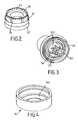
- FIG. 2is a perspective view of an air piston seal component thereof
- FIG. 3is a perspective view of a plunger core component thereof
- FIG. 4is a perspective view of a plunger core sleeve extension incorporating an air outlet valve
- FIG. 5is an axial section of a second embodiment of dispenser pump
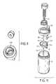
- FIG. 6is an exploded view of the pump components
- FIG. 7is an axial section of a third embodiment of a dispenser pump
- FIG. 8is an exploded view of the components of the third embodiment
- FIG. 9is a perspective view from the top of a plunger core component in the third embodiment.
- FIG. 10is an axial section of a fourth embodiment of dispenser pump having a fixed nozzle
- FIG. 11is an exploded view of the components of the fourth embodiment.
- FIG. 12is an axial cross-section of a fifth embodiment of foamer having a discrete vent cover
- FIG. 13shows enlarged the FIG. 12 embodiment at region B
- FIGS. 14 and 15is similar but with the vent cover removed
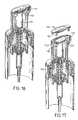
- FIGS. 16 and 17correspond to FIGS. 14 and 15 with the pump components axially sectioned
- FIG. 18shows in axial cross section the top of a sixth embodiment of dispenser, also having a vent cover
- FIG. 19shows the top of the main plunger component of the sixth embodiment with the vent cover removed.
- FIG. 20shows a seventh embodiment of foam dispenser.
- FIGS. 1 to 4show a first embodiment of hand-operated foam dispenser.
- the dispenseris mounted on the threaded neck 92 of a conventional blow-moulded cylindrical container 91 .
- the containerneed not be cylindrical, however.
- the dispenserincludes a one-piece cylinder component 10 e.g. of polypropylene. This includes a lower, smaller-diameter liquid cylinder 102 and an upper larger-diameter air cylinder 101 , with a side vent hole 109 .
- the cylinder component 10is recessed down into the neck 92 of the container and held in place by a threaded retaining collar 95 .
- a valve seat 104is integrally formed, also a socket for a dip tube 94 .
- a plunger 1is mounted to act reciprocally in the air and liquid cylinders 101 , 102 .
- the plungerhas a projecting central stem 13 carrying a piston seal 41 which works in the liquid cylinder 102 .
- a tubular piston-retaining insert 105is snapped into the base of the air cylinder 101 and the liquid piston seal 41 is trapped beneath it; this keeps the plunger in the assembly.
- a return spring 93is fitted around the plunger stem 13 —in the air chamber 16 so as to avoid spring corrosion—and acts to urge the plunger 1 to its uppermost position.
- the air piston 2surrounds the upper part of the plunger stem 13 . Unlike prior art constructions, it is not retained and driven by engagement at the plunger stem but rather by a snap fitting engagement into the lower end of a cap shroud 5 of the plunger.
- This cap shroud 5is of substantially the same diameter as the air cylinder.
- the discrete air piston componentis shown in FIG. 2 and is a generally cylindrical sleeve 23 having a snap rib at the top to locate it at a predetermined degree of axial insertion into the cap shroud interior.
- An outwardly-directed sealing lip 21 , 22 towards its lower endacts against the air cylinder wall.
- pressing down the plunger 1directly (without play or lost motion) operates the air piston 2 in its cylinder.
- a radial annular valve flap 24Projecting radially inwardly from near the top of the sleeve 23 is a radial annular valve flap 24 tapering in thickness towards its edge.
- the nozzle 12communicates with an inner axial downwardly-open tube 11 which forms a top foamer unit housing.
- This tube 11snap fits into an upwardly-open cylindrical tube 32 of a core insert component 3 , trapping in the space between them a foam-generation element 8 in the passage leading to the nozzle 12 .
- This foam-generating element 6has conventional features, being a cylindrical plastics tube 81 fitting closely in the housing tube 11 and having ultrasonically welded across its open ends a disk of coarse nylon mesh 82 (bottom end) and fine nylon mesh 83 (top end).
- the snap fit between the tubes 11 , 32involves snap ribs that fix the relative axial positions of the plunger cap 5 and the insert core 3 .
- the core insert 3(see also FIG. 3) defines a small circular mixing chamber 180 above a floor 38 .
- a hollow cylindrical stud 31Projecting down from the centre of this floor 38 is a hollow cylindrical stud 31 with a set of axial ribs or splines 311 which fit closely, again with a snap fit, into the slightly enlarged top-diameter of the hollow plunger stem 13 .
- the enlarged diameter section at the top of the stem 13is dimensioned so that when the splined stud 31 fits right into it, its top edge has a clearance from the underside of the core insert's floor 38 . This clearance thus communicates with the passages 171 between the splines, immediately before where they pass up through the floor 38 .
- an outward radial flange with a downward cylindrical skirt or core sleeve 33Projecting integrally at the lower end of the core component 3 is an outward radial flange with a downward cylindrical skirt or core sleeve 33 .
- a generally cylindrical core sleeve extension 34Projecting radially in perpendicularly from the bottom edge of this extension 34 is an integral valve lip 341 of progressively decreasing thickness. The bottom of the edge of this lip rests on an annular valve seat ledge 131 extending around near the top of the plunger stem 13 , as seen in FIG. 1 .
- An annular air discharge chamber 17is thereby defined between the top of the stem 13 , the core sleeve extension 34 and the core floor 38 .
- the piston seal 41 of the liquid pistonis of the “sliding seal” type which acts as a discharge valve at the entrance to the liquid discharge passage 15 . That is to say, on the downstroke of the plunger the sliding seal 41 is displaced upwardly relative to the plunger stem 13 and uncovers the plunger stem windows 42 , allowing liquid to flow under pressure from the liquid pump chamber 14 into the liquid discharge passage 15 and up to the narrow discharge passages 171 between the insert splines 311 .
- the action of the pump on pressing down the plungeris as follows. At the same time as liquid is driven up passage 15 as mentioned, air in the air chamber 16 is forced—by the decrease in volume of that chamber—through the air outlet valve flap 341 into the air discharge chamber 17 and radially in from all directions to mix vigorously with the rapid and distributed upflow of liquid. The liquid and air flows mix as they enter the mixing chamber whence they pass through the progressively decreasing meshes and merge as foam from the nozzle 12 .
- the one way action of the air inlet valve flap 24prevents escape of air from the chamber 16 by that route as the plunger is depressed.
- the liquid chamber 14is primed in the conventional way via the inlet valve 104 .
- Airflows in to occupy the air chamber 16 by downward displacement of the air inlet valve flap 24 relative to its valve seat (the bottom edge of the core extension 34 ) under the prevailing pressure difference.
- the resilient sealing of the outlet valve flap 341prevents any liquid from dripping through into the air chamber Air flows into the air chamber 16 from the cap air apace 51 inside the cap shroud 5 which encloses the inlet valve 24 .
- airmay enter the cap air space 51 via channel clearances between channels 25 of the air piston insert sleeve 23 and the bottom rim of the cap shroud 5 .
- airmay enter the cap shroud 5 via an upper opening 19 in the shroud itself (see FIG. 1 ), the air piston sleeve being connected air tightly.
- FIGS. 5 and 6show a second embodiment which in many respects is similar to the first. Analogous components are numbered similarly. One difference here is that the top of the cylinder component 10 is bent right over and round as a threaded retaining collar 106 in one piece with the cylinder component 10 . Another difference in this embodiment is in the formation of the core component 3 and its interaction with the air outlet valve 342 .
- the core component 3is a one-piece integral whole including the hollow piston stem 13 , a generally cylindrical body containing the mixing chamber 180 for the air and liquid and defining a cup which holds the housing tubes for the foam-generating element 8 , as well as the radial flange and downward cylindrical core sleeve 33 .
- the mixing chamber 180is recessed down inside the core 3 and is fully overlapped axially by the annular radial space 17 in between the body of the core 3 and its outer core sleeve 33 .
- the air piston 2 and its integral inlet valve flap 24are generally similar to those in the first embodiment although the cap shroud 5 of the plunger is differently shaped being narrower at the top.
- the inner edge of the inlet valve flap 24makes its sealing engagement against the terminal edge of core sleeve 33 as a valve seat, as in the first embodiment.
- the air outlet valveis not formed integrally with the core sleeve 33 .
- the componentsare dimensioned and their snap positions determined so that the resilient air inlet and outward valve lips are lightly biased, i.e. deformed against their resilience, against their valve seat surfaces. This assures a positive action.
- the air passages leading from the air discharge chamber 17 into the mixing chamber 180are not shown in the section of FIG. 5, but can be seen in the view of the corresponding component in FIG. 9 . They are provided as a series of tangentially-inclined radially-extending slots leading in through the central boss of the core 3 and from the space 17 into the chamber 180 at the same axial level.
- the baffle 132(formed as a disk 132 with a serrated edge: see FIG. 6) projects freely into the centre of the mixing chamber 180 and does not project into the top of the liquid discharge passage 15 . Liquid rising from the discharge passage 15 strikes the baffle 132 directly and is scattered for mixing with the radially/tangentially impinging air streams. Prom there the air/liquid mix rises through a hole into an upper part 180 ′ Of the mixing chamber, inside a lower foamer housing tube 32 formed integrally with the baffle disk 132 , thence to pass through the foam unit 8 .
- Access to the cap air spacemay be through a set of channels between shroud and air piston 2 , as in the first embodiment, or through a hole 19 in the top of the shroud as mentioned previously.
- FIG. 5also shows an outer cover cap 107 (a similar cap used for the FIG. 1 embodiment has not been shown) for shipping.
- FIG. 7shows a third embodiment in which the conformation of the pump core 3 and the air inlet and outlet valves is essentially the same as the second embodiment above.
- a slightly different form of baffle 133is used.
- the container 91 in this embodimenthas a more standard narrow neck and the pump is specially designed to fit on it.
- the air cylinder 101is constructed so that the deep peripheral trough, down into which the piston seal slides, fits down around the outside of the neck and is internally threaded to engage it.
- the liquid cylinder 102is still formed in one piece with the air cylinder 101 , and is the only part projecting down inside the neck.
- vent hole 109is through an upper part of the side wall of the air cylinder 101 , and valved by alternate covering and uncovering by the air piston (as is known in the prior art).
- the air cylinderdoes not share a wall with the container's internal space, so instead a vent passageway is defined (by means of surface grooves) between the piston-retaining insert 105 and a transitional section of the cylinder component 10 between the air cylinder and the liquid cylinder portions. Compensation air can reach this vent channel 191 via the threaded engagement between the cylinder component 10 and the container neck 92 .
- FIGS. 10 and 11show a substantially different embodiment in which the discharge nozzle 12 remains fixed in relation to the container 91 during dispensing. This is achieved by leading the air and liquid discharge channels 15 , 17 a out of their respective cylinders within the container interior, and leading them up alongside the pump body in a fixed pump body discharge module 85 .
- the plunger 1carries a simple top button shroud 5 in which the piston stem 13 and the core sleeve 33 protect down concentrically with one another, integrally from the top web of the cap shroud 5 . Because there is no need to accommodate the discharge arrangement in the plunger, and in order to minimise the axial height of the arrangement, the liquid cylinder 102 is brought up inside the air cylinder 101 (although still concentrically and in one piece with it), and the liquid piston seal 41 on the end of the stem 13 is a simple one, no longer needing to form any valve.
- Enclosed valved passagewayscan be formed using moulded components by means of a lower basin component 111 clipped around the bottom of the cylinder component 10 .
- the passagewaysare formed between shaped opposed surfaces and walls of these components.
- a flexible valve disc 46is trapped between the components 10 , 111 and provides an outlet flap valve for the liquid leading into the liquid discharge passage 15 .
- This passageis defined initially through a radial tube of the basin component 111 and then up through an axial side tube having a crenellated top opening immediately below the foam generating module 8 .
- the air cylinder 101is formed in one piece with the fixed discharge passage module 85 , and the two communicate via an air discharge opening 17 a near the bottom of the air cylinder 16 .
- An air outlet valve componentin the form of a sleeve with a conically-divergent flexible upper part, fits around the liquid discharge tube at this point in an annular air discharge space 17 .
- air driven from the air chamber 16 on pressing the plunger 1passes the outlet valve lip 442 and mingles with the upflow of liquid via the crenellations at a mixing zone 208 .
- the formation of foamas essentially as previously.
- the function of the air inlet valve 24 contained within the plungeris also the same as previously, although the plunger construction is simplified. A special issue with this pump is closing the liquid discharge valve for shipping purposes.
- a fifth embodiment of dispensing systemcomprises a foam-generating dispenser 1 , 10 , secured by a threaded cap 95 onto the neck of a container 91 .
- the pump body elementprovides two coaxial cylinder portions, a lower liquid cylinder 121 defining a liquid pump chamber 127 and an upper, larger-diameter air cylinder defining an air chamber 126 .
- the plunger 1carries two pistons, an inner liquid piston 122 and an outer air piston 125 working in their respective cylinders. Liquid from the liquid chamber (which has a conventional ball inlet valve 129 ) is pumped up the hollow stem 124 of the liquid piston to a foam generating area 128 where it emerges as fine jets. In the same stroke of the pump, air is forced from the air chamber 126 through the air outlet valve 1212 .
- a core component 143encloses the foam-generating region where the pumped air and liquid meet and are forced together up through a foam-regulating element having upper and lower meshes 142 , 141 .
- This elementis seated in the discharge channel 134 of the plunger head, which leads vertically up to the top of the plunger and then sideways to a spout 132 .
- the top of the plungeris a one-piece moulded element having a central tubular extension 133 providing the discharge passage and an outer cylindrical shroud 131 , with an interior space 136 between them around the central tube 133 and the foam-generating core 143 .
- the air piston 125is snapped sealingly into the bottom of this plunger shroud 131 at a joint 138 .
- the air intake valve 146 for the air pumptherefore opens from the interior space 136 of the plunger.
- the outer surface of the shroud 131fits closely through the central hole of the securing cap 95 , which has a sealing lip 151 to ensure a seal.
- the dispenseris designed for use in the shower and this seal keeps falling water out of the pump.
- dip tube 94from the pump inlet down into the container and a cover cap 107 .
- Supply of air into the air cylinder 126is from the plunger interior 136 , so it is important to allow air into that interior space. At the same time it is important to keep water out of it, since any such water will accumulate in the air cylinder 126 and gradually spoil foam production.
- the top (integral) wall 137 of the plunger casingslopes down towards the rear.
- a discrete moulded plastics cover element 156is clipped onto it by means of downward prongs 161 fitting tightly in corresponding sockets 130 of the plunger casing.
- the top face of the plunger casingis slightly recessed inside a peripheral rim 1310 (see FIG. 15 ).
- the cover 156fits down closely inside this to form a smooth exterior contour.
- the rim 1310is interrupted by a notch 172 .
- the cover 156has a rearward lug 166 which fits into this notch, covering it from above but not blocking off its rear opening.
- the top surface of the top wall 137 of the plungerhas two curved grooves 171 which communicate with the rear notch 172 and lead forward from it in a curve around to either side of the region above the discharge channel tube 133 . These grooves do not penetrate the top wall except at their forward extremities where each has a through hole 173 communicating with the plunger's interior space 136 .
- the underside of the cover 156has a smooth surface closely complementing the top of the plunger wall 137 except at these grooves 171 , where the cover is plain and acts as a lid to form closed channels leading between the cover and plunger wall 137 forward from the rear notch 172 to each of the front through-openings 173 .
- This hole 1211is closed by the air piston in its rest position i.e. the upward position, towards which it is biased by a pump spring 123 .
- the plunger shroud 131is sealed by the lip 151 in the cap 95 , and the air cylinder inlet 146 is the only way out of the plunger's interior space, compensation air for the container interior does not come through the plunger. Instead, a small localised notch 1213 in the cap underside provides a leak between the space below the cap and the threaded engagement region between the cap and the outside of the container neck. Sufficient air can pass here from the outside down to the hole 1211 to compensate for the relatively small volume of liquid dispensed in each stroke.
- FIGS. 18, 19show details of the venting of the internal plunger space of a further embodiment, whose plunger head has a large, rounded top surface 237 designed for palm actuation.
- the top of the main plunger elementhas a shallow circular depression 2378 with a central upstanding cylindrical socket 2371 .
- a pair of vent holes 273is provided through the top wall of the plunger head to the internal cavity thereof, to either side of the plunger course leave in this central region.
- a domed, circular cover element 206has a downward central stud 2062 by which it clips into the socket 2371 to cover the circular area 2378 with its through-holes 273 .
- This cover element 206which preferably has a colour contrast with the remainder of the plunger, provides a runoff for water which lands on the plunger top while at the same time leaving a small annular crack around its periphery through which venting air can easily enter the plunger interior via the holes 273 , for refilling the air cylinder after each foam-dispensing stroke.
- Other elements of the dispenserare substantially as seen previously.
- FIG. 20describes a further embodiment, again corresponding in general respects to the embodiment of FIG. 1 but with the following significant differences.
- the plungeris adapted to cover the air vent as in the previous two embodiments.
- the cover element 406is not a mere adjunct but rather constitutes the entire top of the plunger 1 , comprising in an integral one-piece whole the discharge nozzle 412 , top plunger wall with its rearwardly-inclined surface and finger-engagement depression, a downward central core sleeve portion 411 which forms the top part of the housing for the permeable filter element 81 , and a downward short outer skirt 4063 .
- This outer skirt 4063is a tight snap fit into the top of the main cylindrical tubular wall 5 of the plunger cap.
- the outer tubular wall 5is molded in one piece, via a lower bridge having vent apertures 314 , with the upwardly-projecting tubular wall or sleeve 32 that compliments the downward sleeve 411 to enclose the mesh module 81 . This avoids increasing the component count.
- the rear of the downward skirt 4063 of the cover plug 406is interrupted by a narrow notch 4064 which in the assembled plunger cap aligns with an exterior shaped notch 511 adjacent the top rim of the tubular wall 51 , to the rear side.
- the rear edge of the cover plug 406has an overhang 421 which slides down over this notch but at a clearance, so that the vent channel is defined between the two components to extend upwardly from its rear entry opening, over the top edge of the wall 5 via a small clearance and into the cap interior via the notch 4064 . From the cap interior, the air can reach the air cylinder inlet valve (which is as in the previous embodiments) via the vent apertures 314 .
- the simple open tubular formation of the plunger wall 5enables the lower edge of the this tube to be moulded with an integral radaial flange 52 .
- This flangeretains the plunger more securely in the pump, by engagement beneath the edge of the securing cap.
- the splined plug 31which fits into the liquid discharge passage to provide a liquid discharge in the form of an essentially tubular high-velocity curtain flow.
- the plug 31is a discrete component fitting into the top of the liquid discharge stem. As before the air discharge is brought in to impinge radially inwardly on this curtain flow before the mixed flows rise through the meshes.
- a further modificationrelates to venting of the container to compensate for dispensed liquid.
- this ventingwas by way of the small opening 109 through the air cylinder 101 , intended to be covered in the rest condition by the air piston.
- a holemay allow liquid to escape between the plunger sleeve and threaded retaining cap, or into the air cylinder, particularly if the container is tipped.
- the present embodimentallows venting instead between the threads of the container neck 92 and the retaining collar. Leakage is avoided by an elastomeric gasket 199 trapped beneath the pump body flange and the container neck edge.
- Such a gasketis conventionally used and would normally prevent venting, but in this variant the container body flange has a localized vent opening 1001 and the gasket 199 has a thinner, more flexible inner flange projecting out to cover this opening to form a vent valve. Under normal conditions this keeps air out and prevents escape of liquid with the bottle tipped. Negative pressure in the container after dispensing draws air in by flexing the lip 299 .
Landscapes
- Closures For Containers (AREA)
- Containers And Packaging Bodies Having A Special Means To Remove Contents (AREA)
- Organic Low-Molecular-Weight Compounds And Preparation Thereof (AREA)
- Nozzles (AREA)
- Surgical Instruments (AREA)
- Massaging Devices (AREA)
Abstract
Description
Claims (27)
Applications Claiming Priority (5)
| Application Number | Priority Date | Filing Date | Title |
|---|---|---|---|
| GB0022700AGB0022700D0 (en) | 2000-09-15 | 2000-09-15 | Dispenser pumps |
| GB0022700 | 2000-09-15 | ||
| GB0022700.9 | 2000-09-15 | ||
| GB0105003 | 2001-02-28 | ||
| GB0105003AGB0105003D0 (en) | 2001-02-28 | 2001-02-28 | Dispenser pumps |
Publications (2)
| Publication Number | Publication Date |
|---|---|
| US20020070238A1 US20020070238A1 (en) | 2002-06-13 |
| US6612468B2true US6612468B2 (en) | 2003-09-02 |
Family
ID=26245012
Family Applications (1)
| Application Number | Title | Priority Date | Filing Date |
|---|---|---|---|
| US09/954,664Expired - LifetimeUS6612468B2 (en) | 2000-09-15 | 2001-09-12 | Dispenser pumps |
Country Status (8)
| Country | Link |
|---|---|
| US (1) | US6612468B2 (en) |
| EP (2) | EP1190775B1 (en) |
| CN (1) | CN1179867C (en) |
| AT (1) | ATE257038T1 (en) |
| BR (1) | BR0104095B1 (en) |
| DE (1) | DE60101656T2 (en) |
| DK (1) | DK1190775T3 (en) |
| HK (1) | HK1045660B (en) |
Cited By (65)
| Publication number | Priority date | Publication date | Assignee | Title |
|---|---|---|---|---|
| US20030221808A1 (en)* | 2002-05-31 | 2003-12-04 | Kimberly-Clark Worldwide, Inc. | Method of applying a foam composition to a tissue product |
| US20030224106A1 (en)* | 2002-05-31 | 2003-12-04 | Kimberly-Clark Worldwide, Inc. | Use of gaseous streams to aid in application of foam to tissue products |
| US20030232135A1 (en)* | 2002-05-31 | 2003-12-18 | Kimberly-Clark Worldwide, Inc. | Application of foam to tissue products using a liquid permeable partition |
| US20040229763A1 (en)* | 2003-02-28 | 2004-11-18 | The Procter & Gamble Company | Cleaning kit and/or a dishwashing kit containing a foam-generating dispenser and a cleaning and/or dishwashing composition |
| US20040229963A1 (en)* | 2003-02-28 | 2004-11-18 | The Procter & Gamble Company | Foam-generating kit containing a foam-generating dispenser and a composition containing a high level of surfactant |
| US20040254253A1 (en)* | 2003-02-28 | 2004-12-16 | The Procter & Gamble Company | Foam-generating kit containing a foam-generating dispenser and a high viscosity composition |
| US20050067435A1 (en)* | 2003-09-25 | 2005-03-31 | Unilever Home & Personal Care Usa, Division Of Conopco, Inc. | Foam dispensing article |
| US20050109800A1 (en)* | 2003-11-24 | 2005-05-26 | Cactrus Drink Systems Inc. | Bottle cap |
| US20060049208A1 (en)* | 2004-09-09 | 2006-03-09 | Daansen Warren S | Slit valves and dispensing nozzles employing same |
| US20060246013A1 (en)* | 2005-05-02 | 2006-11-02 | Ocusoft, Inc. | Pump system for dispensing foaming eyelid cleanser |
| US20060283887A1 (en)* | 2005-01-14 | 2006-12-21 | Rowshan Jahan | Up-lock seal for dispenser pump |
| USD536971S1 (en) | 2006-04-28 | 2007-02-20 | Aminak & Associates, Inc. | Pump actuator |
| US20070045350A1 (en)* | 2005-08-30 | 2007-03-01 | Tianda Lin | Foam pump |
| US20070051426A1 (en)* | 2003-09-10 | 2007-03-08 | Btg International Limited | Apparatus and method for dispensing foam |
| USD539143S1 (en) | 2006-09-01 | 2007-03-27 | Arminak & Associates | Foamer pump head |
| JP2007508127A (en)* | 2003-09-23 | 2007-04-05 | ケルテック・ベスローテン・フエンノートシャップ | Dispenser for concentrated injection |
| US20070119864A1 (en)* | 2005-11-25 | 2007-05-31 | Yih Tai Glass Industrial Co., Ltd. | Piston device and a fluid/gas drawing apparatus and a foam producing apparatus using such piston device |
| US20070241137A1 (en)* | 2006-04-14 | 2007-10-18 | Willis Daniel M | Foam soap generator |
| US20080035677A1 (en)* | 2004-09-09 | 2008-02-14 | Daansen Warren S | Nozzle tip with slit valve for fluid dispenser |
| US20080075670A1 (en)* | 2003-12-12 | 2008-03-27 | Eran Eilat | Compositions for Treatment of Ear Disorders and Methods of Use Thereof |
| US20080083783A1 (en)* | 2006-10-10 | 2008-04-10 | Continentalafa Dispensing Company | Rotating Dispenser Head with Locking and Venting Closure Connector for an Air Foaming Pump Dispenser |
| US20080093386A1 (en)* | 2006-10-23 | 2008-04-24 | Arminak & Associates, Inc. | Foamer pump |
| US20090014453A1 (en)* | 2007-01-08 | 2009-01-15 | Christian Bleys | Collar for mounting a protective cap and assembly for storage and delivery of a gas comprising such a collar |
| US20090039111A1 (en)* | 2007-08-10 | 2009-02-12 | Xufeng Tu | Foam Pump |
| US20090057345A1 (en)* | 2007-08-31 | 2009-03-05 | Dukes Stephen A | Fluid dispenser |
| USD592899S1 (en) | 2008-04-25 | 2009-05-26 | Impact Products Llc | Soap dispenser |
| US20090166382A1 (en)* | 2007-12-28 | 2009-07-02 | Snodgrass David L | Foam pump assembly |
| US20090200338A1 (en)* | 2008-02-08 | 2009-08-13 | Quinlan Robert L | Bifurcated stem foam pump |
| US20090200337A1 (en)* | 2008-02-08 | 2009-08-13 | Quinlan Robert L | Bifurcated stem foam pump |
| US20090200339A1 (en)* | 2008-02-08 | 2009-08-13 | Quinlan Robert L | Bifurcated foam pump assembly |
| US20090212074A1 (en)* | 2005-04-20 | 2009-08-27 | Keltec B.V. | Dispenser with improved supply-closing means |
| US20090236371A1 (en)* | 2006-07-11 | 2009-09-24 | Rexam Airspray N.V. | Foam Dispenser |
| US20090255957A1 (en)* | 2005-07-29 | 2009-10-15 | Yoshino Kogyosyo Co., Ltd. | Discharge Container |
| US20090294478A1 (en)* | 2008-05-29 | 2009-12-03 | Gojo Industries, Inc. | Pull actuated foam pump |
| US20100111735A1 (en)* | 2008-11-06 | 2010-05-06 | Xufeng Tu | Foam Pump |
| US20100193547A1 (en)* | 2007-08-02 | 2010-08-05 | Leafgreen Limited | Manual pump type fluid dispenser and a method of manufacturing such a dispenser |
| US20100303971A1 (en)* | 2009-06-02 | 2010-12-02 | Whitewave Services, Inc. | Producing foam and dispersing creamer and flavor through packaging |
| US20100314417A1 (en)* | 2007-11-01 | 2010-12-16 | Chong Woo Co., Ltd. | Foam production pump not causing contamination of contents |
| USD636668S1 (en) | 2008-03-24 | 2011-04-26 | Mary Kay Inc. | Dip tubes |
| US20110168739A1 (en)* | 2005-11-07 | 2011-07-14 | MeadWestvasco Calmar Netherlands B.V. | Dispenser unit with improved air supply |
| JP2012206760A (en)* | 2011-03-30 | 2012-10-25 | Yoshino Kogyosho Co Ltd | Foam dispenser |
| US8336740B1 (en) | 2005-11-02 | 2012-12-25 | Daansen Warren S | Fluid dispenser and pump adapter system therefor |
| US8360283B1 (en)* | 2011-08-17 | 2013-01-29 | Zhejiang JM Industry Co., Ltd | Liquid foaming pump |
| US8376192B2 (en) | 2008-03-24 | 2013-02-19 | Mary Kay Inc. | Apparatus for dispensing fluids using a press-fit diptube |
| WO2013063180A1 (en)* | 2011-10-25 | 2013-05-02 | Rieke Corporation | Pump dispenser with an inclined nozzle |
| US8499981B2 (en) | 2008-02-08 | 2013-08-06 | Gojo Industries, Inc. | Bifurcated stem foam pump |
| US20140069960A1 (en)* | 2011-05-06 | 2014-03-13 | Chantal Chaussard | Foam or mousse-producing device |
| US8678241B2 (en)* | 2012-08-27 | 2014-03-25 | Ya-Tsan Wang | Foam spray head assembly |
| US20140117053A1 (en)* | 2012-10-31 | 2014-05-01 | Gojo Industries, Inc. | Foam pumps with lost motion and adjustable output foam pumps |
| US8814005B2 (en) | 2012-04-27 | 2014-08-26 | Pibed Limited | Foam dispenser |
| US8940321B2 (en) | 2003-12-12 | 2015-01-27 | Otic Pharma Ltd. | Compositions for treatment of ear disorders and methods of use thereof |
| JP2015098328A (en)* | 2013-11-18 | 2015-05-28 | 花王株式会社 | Foam dispenser |
| US9265385B2 (en) | 2005-07-26 | 2016-02-23 | Rieke Corporation | Adaptation device for production of foam |
| US20170020348A1 (en)* | 2015-07-23 | 2017-01-26 | William J. Schalitz | Disposable Soap Dispenser |
| US20170035257A1 (en)* | 2015-08-05 | 2017-02-09 | Gojo Industries, Inc. | Pumps with restrictor-based lost motion |
| US9789502B2 (en) | 2008-06-05 | 2017-10-17 | Mary Kay Inc. | Apparatus for dispensing fluids using a removable bottle |
| US9962723B2 (en) | 2012-12-20 | 2018-05-08 | Rieke Corporation | Foam dispenser with reversible valve |
| US10293353B2 (en) | 2017-04-25 | 2019-05-21 | Gpcp Ip Holdings Llc | Automated flowable material dispensers and related methods for dispensing flowable material |
| JP2020147292A (en)* | 2019-03-11 | 2020-09-17 | 株式会社丸一 | Pump for discharge of fluid |
| US10823161B2 (en)* | 2015-05-12 | 2020-11-03 | Gregory L. Indruk | Foam pump and dispenser employing same |
| WO2021051058A1 (en) | 2019-09-13 | 2021-03-18 | Rieke Llc | Valve and gasket tolerant to pressure-differentials |
| US11027909B2 (en) | 2018-08-15 | 2021-06-08 | Gpcp Ip Holdings Llc | Automated flowable material dispensers and related methods for dispensing flowable material |
| US11110473B2 (en)* | 2017-05-19 | 2021-09-07 | King Tsang Chung | Foam pump sprayer |
| US11236737B2 (en)* | 2015-05-12 | 2022-02-01 | Gregory L. Indruk | Foam pump and dispenser employing same |
| US12064063B2 (en) | 2019-09-23 | 2024-08-20 | Gpcp Ip Holdings Llc | Automated toilet seat cover dispenser |
Families Citing this family (65)
| Publication number | Priority date | Publication date | Assignee | Title |
|---|---|---|---|---|
| GB0208806D0 (en) | 2002-04-17 | 2002-05-29 | Rieke Corp | Dispenser pumps |
| US6868990B2 (en) | 2002-09-26 | 2005-03-22 | Emsar, Inc. | Fluid dispenser with shuttling mixing chamber |
| US6923346B2 (en)* | 2002-11-06 | 2005-08-02 | Continental Afa Dispensing Company | Foaming liquid dispenser |
| US6644516B1 (en) | 2002-11-06 | 2003-11-11 | Continental Afa Dispensing Company | Foaming liquid dispenser |
| NL1022633C2 (en)* | 2003-02-10 | 2004-08-12 | Keltub B V | Improved foaming unit. |
| US7004356B1 (en) | 2003-07-28 | 2006-02-28 | Joseph S. Kanfer | Foam producing pump with anti-drip feature |
| US6840408B1 (en) | 2003-08-25 | 2005-01-11 | Continental Afa Dispensing Company | Air foam pump with shifting air piston |
| US7389893B2 (en) | 2003-09-10 | 2008-06-24 | Rieke Corporation | Inverted dispensing pump |
| CN100413596C (en)* | 2003-09-17 | 2008-08-27 | 丁要武 | Small discharge emulsion pump |
| US7086610B2 (en)* | 2004-06-24 | 2006-08-08 | Johnsondiversey, Inc. | Vented dispenser |
| EP1791647B1 (en)* | 2004-09-25 | 2008-01-09 | Obrist Closures Switzerland GmbH | Dispensing pump |
| ITVI20050053A1 (en)* | 2005-02-25 | 2006-08-26 | Taplast Spa | DEVICE FOR THE DELIVERY OF GAS-LIQUID MIXTURES |
| CN100571893C (en)* | 2005-04-20 | 2009-12-23 | Kel技术有限公司 | Dispenser with improved feed shut-off |
| US7337930B2 (en)* | 2005-05-20 | 2008-03-04 | Gotohti.Com Inc. | Foaming pump with improved air inlet valve |
| US20070045349A1 (en)* | 2005-08-25 | 2007-03-01 | Continental Afa Dispensing Company | Liquid dispensing pump with shifting liquid piston |
| US7543722B2 (en)* | 2005-09-06 | 2009-06-09 | Joseph S. Kanfer | Foam soap generator and pump |
| NL1031092C2 (en)* | 2006-02-07 | 2007-08-08 | Airspray Nv | Self-cleaning foam dispenser. |
| CN100453187C (en)* | 2006-05-09 | 2009-01-21 | 黄建壮 | Hand beating miniature sprayer |
| US7735688B2 (en)* | 2006-10-10 | 2010-06-15 | Meadwestvaco Calmar, Inc. | Rotating collar and locking and venting closure connector for an air foaming pump dispenser |
| FR2907034B1 (en) | 2006-10-12 | 2008-12-26 | Gerard Sannier | CORROSION RESISTANT FOAM PUMP |
| GB0620943D0 (en)* | 2006-10-20 | 2006-11-29 | Glaxosmithkline Consumer Healt | Novel device |
| WO2009038452A1 (en)* | 2007-09-17 | 2009-03-26 | Rexam Airspray N.V. | Foam dispensing assembly |
| US8365963B2 (en)* | 2008-01-30 | 2013-02-05 | Evonik Stockhausen, Llc | Fluid dispenser selectively secured to a countertop |
| US8020731B2 (en)* | 2008-01-30 | 2011-09-20 | Evonik Stockhausen, Llc | Dispenser |
| CN102056677B (en)* | 2008-06-10 | 2014-02-26 | 米德韦斯特瓦科卡尔马有限责任公司 | fluid discharge head |
| GB0815881D0 (en) | 2008-09-01 | 2008-10-08 | Rieke Corp | Liquid dosing devices |
| US9433960B2 (en) | 2008-09-01 | 2016-09-06 | Rieke Corporation | Liquid dosing devices |
| US8418889B2 (en) | 2010-01-11 | 2013-04-16 | Rieke Corporation | Inverted dispenser pump with liquid inlet cup valve |
| GB201000601D0 (en) | 2010-01-14 | 2010-03-03 | Rieke Corp | Pump dispensers |
| US20110272432A1 (en)* | 2010-05-10 | 2011-11-10 | Baughman Gary M | Foam dispenser |
| TWI559884B (en)* | 2010-05-31 | 2016-12-01 | Kao Corp | Foam ejecting container |
| GB201011144D0 (en) | 2010-07-01 | 2010-08-18 | Rieke Corp | Dispensers |
| GB201011143D0 (en) | 2010-07-01 | 2010-08-18 | Rieke Corp | Dispensers |
| JP5829461B2 (en)* | 2010-08-30 | 2015-12-09 | 花王株式会社 | Hair dyeing or decoloring method and hair dyeing or decoloring kit |
| US9101952B2 (en)* | 2011-06-06 | 2015-08-11 | Gojo Industries, Inc. | Modular pump |
| FR2994109B1 (en) | 2012-08-06 | 2014-09-05 | Gerard Sannier | DEVICE FOR PRODUCING RECHARGEABLE FOAM |
| WO2014099228A1 (en)* | 2012-12-20 | 2014-06-26 | Arminak & Associates, Llc | Foam dispenser with an integral piston valve |
| JP6228364B2 (en)* | 2013-01-31 | 2017-11-08 | 日本クロージャー株式会社 | Foam cap |
| US11643946B2 (en) | 2013-10-02 | 2023-05-09 | Aerocore Technologies Llc | Cleaning method for jet engine |
| CN104724362B (en)* | 2013-12-18 | 2018-07-20 | 上海宝钢工业技术服务有限公司 | Oil drum device with pneumatic type agitating function |
| KR101501027B1 (en)* | 2014-06-16 | 2015-03-12 | (주)연우 | Pump vessel for dispensing of capsule |
| USD799959S1 (en)* | 2015-05-13 | 2017-10-17 | Albea Services | Dispenser head |
| GB201509828D0 (en) | 2015-06-05 | 2015-07-22 | Rieke Packaging Systems Ltd | Foam dispensers |
| GB2543845A (en)* | 2015-11-02 | 2017-05-03 | Deb Ip Ltd | Foaming component |
| NL2015724B1 (en) | 2015-11-04 | 2017-05-24 | Gab Eng & Dev B V | Storage holder for a dispenser. |
| GB201603949D0 (en)* | 2016-03-08 | 2016-04-20 | Rieke Packaging Systems Ltd | Foam dispensers |
| NL2016644B1 (en) | 2016-04-20 | 2017-11-07 | Gab Eng & Development B V | Storage holder for a dispenser |
| CA2935908C (en)* | 2016-07-12 | 2023-10-17 | Op-Hygiene Ip Gmbh | Piston pump with locking pistons |
| RU2715848C1 (en)* | 2016-07-18 | 2020-03-03 | Рпк Брамлаге Гмбх | Dispenser for masses from liquid to pastelike |
| JP6582027B2 (en) | 2016-09-29 | 2019-09-25 | 花王株式会社 | Foam discharge container |
| NL2018027B1 (en)* | 2016-12-20 | 2018-06-28 | Douwe Egberts Bv | Drainage connector unit and assembly for the drainage of liquid waste of beverage dispensing devices |
| GB201705198D0 (en)* | 2017-03-31 | 2017-05-17 | Rapid Washrooms Ltd | Soap dispenser |
| PL3621578T3 (en)* | 2017-05-10 | 2022-06-13 | Unilever Ip Holdings B.V. | SELF-FOAMING COMPOSITION WITH LOW VISCOSITY AND HIGH POLYOL CONTENT |
| GB201718524D0 (en)* | 2017-11-09 | 2017-12-27 | Rieke Packaging Systems Ltd | Pump dispensers, especially foam dispensers |
| TWI802619B (en)* | 2017-12-15 | 2023-05-21 | 日商花王股份有限公司 | foam dispenser |
| WO2019117285A1 (en) | 2017-12-15 | 2019-06-20 | 花王株式会社 | Foam discharger |
| FR3075650B1 (en)* | 2017-12-22 | 2020-01-03 | Aptar France Sas | DEVICE FOR DISPENSING FLUID PRODUCT. |
| US11236794B2 (en)* | 2018-01-03 | 2022-02-01 | Silgan Dispensing Systems Corporation | Dispensing pump with polymer spring, base venting and flow baffle |
| CN109717598B (en)* | 2018-11-26 | 2021-09-21 | 佛山市上富塑料制品有限公司 | Cosmetic bottle with pressure |
| GB2583944B (en) | 2019-05-14 | 2021-05-12 | Scopenext Ltd | Flap valve with improved retainer |
| CN112401713B (en)* | 2019-08-22 | 2025-05-16 | 小卫(上海)生物科技有限公司 | Air intake structure, foam generating device and hand washing machine |
| US20230036640A1 (en)* | 2019-12-31 | 2023-02-02 | Rieke Packaging Systems Limited | Low temperature reciprocating pump |
| CN113401493B (en)* | 2021-06-24 | 2023-06-13 | 浙江优肯包装有限公司 | Foam pump |
| US12186771B2 (en)* | 2023-01-24 | 2025-01-07 | Silgan Dispensing Systems Corporation | Foam pump utilizing a compression spring assembly |
| WO2024196739A2 (en)* | 2023-03-17 | 2024-09-26 | Gojo Industries, Inc. | Improved table top dispenser |
Citations (61)
| Publication number | Priority date | Publication date | Assignee | Title |
|---|---|---|---|---|
| DE1201684B (en) | 1964-01-28 | 1965-09-23 | Erich Pfeiffer K G Metallwaren | Single-acting, hand-operated piston pump installed in a vessel |
| DE2001921A1 (en) | 1969-01-17 | 1970-07-23 | Diamond Int Corp | Reciprocating liquid dispensing pump |
| DE1943583A1 (en) | 1969-08-27 | 1971-03-04 | Pfeiffer Kg Ing Erich | Single-acting, hand-operated piston pump |
| GB1389615A (en) | 1968-09-23 | 1975-04-03 | Wright Hershel Earl | Device for producing foam |
| US3973701A (en) | 1975-06-06 | 1976-08-10 | Glasrock Products, Inc. | Foam generating and dispensing device |
| DE2505493A1 (en) | 1973-03-26 | 1976-08-19 | Hirosi Kondo | Valve housing type spray head attachment - has valve unit system with flow medium cut off device within valve housing |
| DE2825223A1 (en) | 1977-06-06 | 1978-12-21 | Aladdin Ind Inc | PUMP SPOUT FOR INSULATED CONTAINERS |
| DE3104321A1 (en) | 1980-02-13 | 1981-12-17 | Douglas F. 90045 Los Angeles Calif. Corsette | "DISPENSER PUMP" |
| DE3105371A1 (en) | 1980-02-13 | 1981-12-24 | Douglas F. 90045 Los Angeles Calif. Corsette | LIQUID DISPENSER |
| JPS5720285A (en) | 1980-07-12 | 1982-02-02 | Toshio Tanikado | Constitution of ball passage for pinball automatic vending machine |
| JPS57111362A (en) | 1980-11-19 | 1982-07-10 | Ici Ltd | Method of cladding electroconductive material |
| JPS582459A (en) | 1981-06-26 | 1983-01-08 | Automob Antipollut & Saf Res Center | Egr controller |
| JPS5823415A (en) | 1981-08-04 | 1983-02-12 | Mitsubishi Electric Corp | Mold structural electric apparatus |
| DE3134265A1 (en) | 1981-08-29 | 1983-03-10 | Robert Finke KG, 5950 Finnentrop | ON A CONTAINABLE PUMP |
| CA1150687A (en) | 1980-06-13 | 1983-07-26 | Realex Corporation | Vent-sealing, down-locked pump dispenser |
| US4432496A (en) | 1981-12-08 | 1984-02-21 | Toyo Seikan Kaisha, Ltd. | Foam liquid dispensing device |
| JPS6024426A (en) | 1983-07-20 | 1985-02-07 | Matsushita Electric Ind Co Ltd | Temperature detecting device |
| US4509661A (en) | 1981-11-24 | 1985-04-09 | Toyo Seikan Kaisha, Ltd. | Squeezable container for dispensing foamed sol |
| DE3509178A1 (en) | 1985-03-14 | 1986-09-18 | mega product- und Verpackungsentwicklung Marketing GmbH & Co KG, 5600 Wuppertal | Proportioning pump with pump bellows |
| US4615467A (en) | 1985-07-24 | 1986-10-07 | Calmar, Inc. | Liquid foam dispenser |
| EP0196737A2 (en) | 1985-01-28 | 1986-10-08 | Earl Wright Company | Foam dispensing device |
| JPS6260555A (en) | 1985-09-10 | 1987-03-17 | 高田 勝美 | Container of sterilized hand washing water |
| JPS62101747A (en) | 1985-10-30 | 1987-05-12 | 三條 敏五郎 | Waterproof belt for roof |
| JPS62177653A (en) | 1986-01-31 | 1987-08-04 | Toshiba Corp | Shared memory control method |
| JPS6321250A (en) | 1986-07-14 | 1988-01-28 | 株式会社日立製作所 | Ceramic injection molding composition manufacturing method |
| JPS6323251A (en) | 1986-07-15 | 1988-01-30 | Clarion Co Ltd | Reel lock releasing mechanism |
| JPH01156759A (en) | 1987-12-15 | 1989-06-20 | Dainippon Ink & Chem Inc | Toner composition for developing electrostatic images |
| DE3817632A1 (en) | 1988-05-25 | 1989-11-30 | Mega Prod Verpack Marketing | ESPECIALLY ON BOTTLES OR THE SAME APPLICABLE DOSING PUMP |
| JPH0234774A (en) | 1988-07-25 | 1990-02-05 | Showa Denko Kk | Thin laminated body |
| US4932567A (en) | 1986-10-31 | 1990-06-12 | Koatsukako Co., Ltd. | Container for foamy liquid discharged in small amounts |
| EP0392238A1 (en) | 1989-04-08 | 1990-10-17 | Ing. Erich Pfeiffer GmbH & Co. KG | Dispensing facility for media |
| US5048750A (en) | 1988-04-05 | 1991-09-17 | Supermatic Kunststoff Ag | Device for producing and dispensing foam |
| US5064103A (en)* | 1990-05-23 | 1991-11-12 | Rjs Industries, Inc. | Foam dispenser having a plurality of sieves |
| EP0460154A1 (en) | 1989-12-22 | 1991-12-11 | Wella Ag | Attachment with foam generator for flexible container. |
| US5147087A (en) | 1987-07-08 | 1992-09-15 | Ing. Erich Pfeiffer Gmbh & Co. Kg | Hand-operated applicator for media |
| JPH04293568A (en) | 1991-03-20 | 1992-10-19 | Daiwa Can Co Ltd | Foam spraying pump container |
| US5156307A (en)* | 1990-03-24 | 1992-10-20 | Callahan George E | Dispenser for foaming of a filled liquid material |
| EP0565713A1 (en) | 1990-11-07 | 1993-10-20 | Daiwa Can Company, Limited | Bubble spouting pump vessel |
| US5289952A (en) | 1991-04-30 | 1994-03-01 | L'oreal | Device for dispensing foam, and push-button for a device of this kind |
| EP0613728A2 (en) | 1993-03-05 | 1994-09-07 | Daiwa Can Company | Foam dispensing pump container |
| EP0618147A2 (en) | 1993-02-26 | 1994-10-05 | Bespak plc | Air purge pump dispenser |
| US5445288A (en) | 1994-04-05 | 1995-08-29 | Sprintvest Corporation Nv | Liquid dispenser for dispensing foam |
| US5462208A (en) | 1994-08-01 | 1995-10-31 | The Procter & Gamble Company | Two-phase dispensing systems utilizing bellows pumps |
| EP0736462A1 (en) | 1994-11-17 | 1996-10-09 | Yoshino Kogyosho Co., Ltd. | Container equipped with bubble injection pump |
| US5570819A (en)* | 1992-07-07 | 1996-11-05 | Daiwa Can Company | Foam dispensing pump container |
| JPH091009A (en) | 1995-06-14 | 1997-01-07 | Puresuko Kk | Bubble formation pump type fluid distribution vessel and gas-liquid mixing member |
| JPH0999260A (en) | 1995-08-02 | 1997-04-15 | Puresuko Kk | Bubble forming pump-type fluid dispenser vessel |
| WO1997013585A1 (en) | 1995-10-06 | 1997-04-17 | Park Towers International B.V. | Device for dispensing an air-liquid mixture, in particular foam, and operating unit intended therefor |
| JPH1034035A (en) | 1997-04-04 | 1998-02-10 | Yoshino Kogyosho Co Ltd | Pump vessel for discharging foam |
| US5779104A (en) | 1994-05-02 | 1998-07-14 | Eureka Development Ltd. | Device for generating and dispensing foam |
| JPH10324357A (en) | 1997-05-26 | 1998-12-08 | Daiwa Can Co Ltd | Pump type foaming container |
| WO1999049769A1 (en) | 1998-03-30 | 1999-10-07 | Sprintvest Corporation N.V. | Improved liquid dispenser for dispensing foam |
| WO1999054054A1 (en) | 1998-04-17 | 1999-10-28 | Keltub B.V. | Foam spraying device |
| JP2000051748A (en) | 1998-08-13 | 2000-02-22 | Lion Corp | Foam discharge container |
| JP2000128215A (en) | 1998-10-30 | 2000-05-09 | Daiwa Can Co Ltd | Pump type foaming container |
| JP2000142751A (en) | 1998-11-16 | 2000-05-23 | Shiseido Co Ltd | Container for simultaneous spouting of liquid and bubble |
| JP2000219254A (en) | 1999-01-28 | 2000-08-08 | Yoshino Kogyosho Co Ltd | Foam ejecting container |
| JP2000238871A (en) | 1999-02-25 | 2000-09-05 | Yoshino Kogyosho Co Ltd | Vertical pump type spouting vessel |
| WO2000064593A1 (en) | 1999-04-22 | 2000-11-02 | Valois S.A. | Two-phase dispensing device |
| WO2001039893A1 (en) | 1999-12-02 | 2001-06-07 | Taplast S.P.A. | Cap with spray pump |
| WO2001040077A1 (en) | 1999-12-02 | 2001-06-07 | Taplast S.P.A. | Foams producing device with flow regulation element |
Family Cites Families (2)
| Publication number | Priority date | Publication date | Assignee | Title |
|---|---|---|---|---|
| US4477000A (en)* | 1979-05-10 | 1984-10-16 | Europtool Trust | Apparatus for forming portions of soap foam |
| CH688021A5 (en)* | 1994-07-18 | 1997-04-30 | Cws Ag | Apparatus for formation of soap scum and its use. |
- 2001
- 2001-09-12USUS09/954,664patent/US6612468B2/ennot_activeExpired - Lifetime
- 2001-09-14CNCNB011424117Apatent/CN1179867C/ennot_activeExpired - Lifetime
- 2001-09-14EPEP01307844Apatent/EP1190775B1/ennot_activeExpired - Lifetime
- 2001-09-14EPEP03027676Apatent/EP1405675A3/ennot_activeWithdrawn
- 2001-09-14DKDK01307844Tpatent/DK1190775T3/enactive
- 2001-09-14DEDE60101656Tpatent/DE60101656T2/ennot_activeExpired - Lifetime
- 2001-09-14ATAT01307844Tpatent/ATE257038T1/ennot_activeIP Right Cessation
- 2001-09-17BRBRPI0104095-2Apatent/BR0104095B1/ennot_activeIP Right Cessation
- 2002
- 2002-09-26HKHK02107119.9Apatent/HK1045660B/ennot_activeIP Right Cessation
Patent Citations (67)
| Publication number | Priority date | Publication date | Assignee | Title |
|---|---|---|---|---|
| DE1201684B (en) | 1964-01-28 | 1965-09-23 | Erich Pfeiffer K G Metallwaren | Single-acting, hand-operated piston pump installed in a vessel |
| GB1389615A (en) | 1968-09-23 | 1975-04-03 | Wright Hershel Earl | Device for producing foam |
| DE2001921A1 (en) | 1969-01-17 | 1970-07-23 | Diamond Int Corp | Reciprocating liquid dispensing pump |
| DE1943583A1 (en) | 1969-08-27 | 1971-03-04 | Pfeiffer Kg Ing Erich | Single-acting, hand-operated piston pump |
| DE2505493A1 (en) | 1973-03-26 | 1976-08-19 | Hirosi Kondo | Valve housing type spray head attachment - has valve unit system with flow medium cut off device within valve housing |
| US3973701A (en) | 1975-06-06 | 1976-08-10 | Glasrock Products, Inc. | Foam generating and dispensing device |
| DE2825223A1 (en) | 1977-06-06 | 1978-12-21 | Aladdin Ind Inc | PUMP SPOUT FOR INSULATED CONTAINERS |
| DE3105371A1 (en) | 1980-02-13 | 1981-12-24 | Douglas F. 90045 Los Angeles Calif. Corsette | LIQUID DISPENSER |
| DE3104321A1 (en) | 1980-02-13 | 1981-12-17 | Douglas F. 90045 Los Angeles Calif. Corsette | "DISPENSER PUMP" |
| CA1150687A (en) | 1980-06-13 | 1983-07-26 | Realex Corporation | Vent-sealing, down-locked pump dispenser |
| JPS5720285A (en) | 1980-07-12 | 1982-02-02 | Toshio Tanikado | Constitution of ball passage for pinball automatic vending machine |
| JPS57111362A (en) | 1980-11-19 | 1982-07-10 | Ici Ltd | Method of cladding electroconductive material |
| JPS582459A (en) | 1981-06-26 | 1983-01-08 | Automob Antipollut & Saf Res Center | Egr controller |
| JPS5823415A (en) | 1981-08-04 | 1983-02-12 | Mitsubishi Electric Corp | Mold structural electric apparatus |
| DE3134265A1 (en) | 1981-08-29 | 1983-03-10 | Robert Finke KG, 5950 Finnentrop | ON A CONTAINABLE PUMP |
| US4509661A (en) | 1981-11-24 | 1985-04-09 | Toyo Seikan Kaisha, Ltd. | Squeezable container for dispensing foamed sol |
| US4432496A (en) | 1981-12-08 | 1984-02-21 | Toyo Seikan Kaisha, Ltd. | Foam liquid dispensing device |
| JPS6024426A (en) | 1983-07-20 | 1985-02-07 | Matsushita Electric Ind Co Ltd | Temperature detecting device |
| EP0196737A2 (en) | 1985-01-28 | 1986-10-08 | Earl Wright Company | Foam dispensing device |
| DE3509178A1 (en) | 1985-03-14 | 1986-09-18 | mega product- und Verpackungsentwicklung Marketing GmbH & Co KG, 5600 Wuppertal | Proportioning pump with pump bellows |
| US4615467A (en) | 1985-07-24 | 1986-10-07 | Calmar, Inc. | Liquid foam dispenser |
| JPS6260555A (en) | 1985-09-10 | 1987-03-17 | 高田 勝美 | Container of sterilized hand washing water |
| JPS62101747A (en) | 1985-10-30 | 1987-05-12 | 三條 敏五郎 | Waterproof belt for roof |
| JPS62177653A (en) | 1986-01-31 | 1987-08-04 | Toshiba Corp | Shared memory control method |
| JPS6321250A (en) | 1986-07-14 | 1988-01-28 | 株式会社日立製作所 | Ceramic injection molding composition manufacturing method |
| JPS6323251A (en) | 1986-07-15 | 1988-01-30 | Clarion Co Ltd | Reel lock releasing mechanism |
| US4932567A (en) | 1986-10-31 | 1990-06-12 | Koatsukako Co., Ltd. | Container for foamy liquid discharged in small amounts |
| US5147087A (en) | 1987-07-08 | 1992-09-15 | Ing. Erich Pfeiffer Gmbh & Co. Kg | Hand-operated applicator for media |
| JPH01156759A (en) | 1987-12-15 | 1989-06-20 | Dainippon Ink & Chem Inc | Toner composition for developing electrostatic images |
| US5048750A (en) | 1988-04-05 | 1991-09-17 | Supermatic Kunststoff Ag | Device for producing and dispensing foam |
| DE3817632A1 (en) | 1988-05-25 | 1989-11-30 | Mega Prod Verpack Marketing | ESPECIALLY ON BOTTLES OR THE SAME APPLICABLE DOSING PUMP |
| JPH0234774A (en) | 1988-07-25 | 1990-02-05 | Showa Denko Kk | Thin laminated body |
| EP0392238A1 (en) | 1989-04-08 | 1990-10-17 | Ing. Erich Pfeiffer GmbH & Co. KG | Dispensing facility for media |
| EP0460154A1 (en) | 1989-12-22 | 1991-12-11 | Wella Ag | Attachment with foam generator for flexible container. |
| US5156307A (en)* | 1990-03-24 | 1992-10-20 | Callahan George E | Dispenser for foaming of a filled liquid material |
| US5064103A (en)* | 1990-05-23 | 1991-11-12 | Rjs Industries, Inc. | Foam dispenser having a plurality of sieves |
| DE69017922D1 (en) | 1990-11-07 | 1995-04-20 | Daiwa Can Co Ltd | Blistering pumping vessel. |
| US5271530A (en) | 1990-11-07 | 1993-12-21 | Daiwa Can Company | Foam dispensing pump container |
| EP0565713A1 (en) | 1990-11-07 | 1993-10-20 | Daiwa Can Company, Limited | Bubble spouting pump vessel |
| JPH04293568A (en) | 1991-03-20 | 1992-10-19 | Daiwa Can Co Ltd | Foam spraying pump container |
| US5289952A (en) | 1991-04-30 | 1994-03-01 | L'oreal | Device for dispensing foam, and push-button for a device of this kind |
| US5570819A (en)* | 1992-07-07 | 1996-11-05 | Daiwa Can Company | Foam dispensing pump container |
| EP0618147A2 (en) | 1993-02-26 | 1994-10-05 | Bespak plc | Air purge pump dispenser |
| EP0613728A2 (en) | 1993-03-05 | 1994-09-07 | Daiwa Can Company | Foam dispensing pump container |
| US5445288A (en) | 1994-04-05 | 1995-08-29 | Sprintvest Corporation Nv | Liquid dispenser for dispensing foam |
| US5779104A (en) | 1994-05-02 | 1998-07-14 | Eureka Development Ltd. | Device for generating and dispensing foam |
| US5462208A (en) | 1994-08-01 | 1995-10-31 | The Procter & Gamble Company | Two-phase dispensing systems utilizing bellows pumps |
| EP0736462A1 (en) | 1994-11-17 | 1996-10-09 | Yoshino Kogyosho Co., Ltd. | Container equipped with bubble injection pump |
| US5813576A (en) | 1994-11-17 | 1998-09-29 | Yoshino Kogyosho Co., Ltd. | Container with a pump that mixes liquid and air to discharge bubbles |
| JPH091009A (en) | 1995-06-14 | 1997-01-07 | Puresuko Kk | Bubble formation pump type fluid distribution vessel and gas-liquid mixing member |
| JPH0999260A (en) | 1995-08-02 | 1997-04-15 | Puresuko Kk | Bubble forming pump-type fluid dispenser vessel |
| WO1997013585A1 (en) | 1995-10-06 | 1997-04-17 | Park Towers International B.V. | Device for dispensing an air-liquid mixture, in particular foam, and operating unit intended therefor |
| US6053364A (en) | 1995-10-06 | 2000-04-25 | Airspray N.V. | Device for dispensing an air-liquid mixture, in particular foam, and operating unit intended therefor |
| JPH1034035A (en) | 1997-04-04 | 1998-02-10 | Yoshino Kogyosho Co Ltd | Pump vessel for discharging foam |
| JPH10324357A (en) | 1997-05-26 | 1998-12-08 | Daiwa Can Co Ltd | Pump type foaming container |
| US6082586A (en) | 1998-03-30 | 2000-07-04 | Deb Ip Limited | Liquid dispenser for dispensing foam |
| WO1999049769A1 (en) | 1998-03-30 | 1999-10-07 | Sprintvest Corporation N.V. | Improved liquid dispenser for dispensing foam |
| WO1999054054A1 (en) | 1998-04-17 | 1999-10-28 | Keltub B.V. | Foam spraying device |
| JP2000051748A (en) | 1998-08-13 | 2000-02-22 | Lion Corp | Foam discharge container |
| JP2000128215A (en) | 1998-10-30 | 2000-05-09 | Daiwa Can Co Ltd | Pump type foaming container |
| JP2000142751A (en) | 1998-11-16 | 2000-05-23 | Shiseido Co Ltd | Container for simultaneous spouting of liquid and bubble |
| JP2000219254A (en) | 1999-01-28 | 2000-08-08 | Yoshino Kogyosho Co Ltd | Foam ejecting container |
| JP2000238871A (en) | 1999-02-25 | 2000-09-05 | Yoshino Kogyosho Co Ltd | Vertical pump type spouting vessel |
| WO2000064593A1 (en) | 1999-04-22 | 2000-11-02 | Valois S.A. | Two-phase dispensing device |
| US6398079B1 (en)* | 1999-04-22 | 2002-06-04 | Valois S.A. | Two-phase dispensing device |
| WO2001039893A1 (en) | 1999-12-02 | 2001-06-07 | Taplast S.P.A. | Cap with spray pump |
| WO2001040077A1 (en) | 1999-12-02 | 2001-06-07 | Taplast S.P.A. | Foams producing device with flow regulation element |
Non-Patent Citations (1)
| Title |
|---|
| Patent Abstracts of Japan, vol. 1999, No. 3, Mar. 31, 1999 & JP 10 324357 (Daiwa Can Co Ltd), Dec. 8, 1998. |
Cited By (119)
| Publication number | Priority date | Publication date | Assignee | Title |
|---|---|---|---|---|
| US20030224106A1 (en)* | 2002-05-31 | 2003-12-04 | Kimberly-Clark Worldwide, Inc. | Use of gaseous streams to aid in application of foam to tissue products |
| US20030232135A1 (en)* | 2002-05-31 | 2003-12-18 | Kimberly-Clark Worldwide, Inc. | Application of foam to tissue products using a liquid permeable partition |
| US6797116B2 (en) | 2002-05-31 | 2004-09-28 | Kimberly-Clark Worldwide, Inc. | Method of applying a foam composition to a tissue product |
| US6797319B2 (en)* | 2002-05-31 | 2004-09-28 | Kimberly-Clark Worldwide, Inc. | Application of foam to tissue products using a liquid permeable partition |
| US6835418B2 (en) | 2002-05-31 | 2004-12-28 | Kimberly-Clark Worldwide, Inc. | Use of gaseous streams to aid in application of foam to tissue products |
| US20030221808A1 (en)* | 2002-05-31 | 2003-12-04 | Kimberly-Clark Worldwide, Inc. | Method of applying a foam composition to a tissue product |
| US7651992B2 (en)* | 2003-02-28 | 2010-01-26 | The Procter & Gamble Company | Foam-generating kit containing a foam-generating dispenser and a composition containing a high level of surfactant |
| US20040229763A1 (en)* | 2003-02-28 | 2004-11-18 | The Procter & Gamble Company | Cleaning kit and/or a dishwashing kit containing a foam-generating dispenser and a cleaning and/or dishwashing composition |
| US20040229963A1 (en)* | 2003-02-28 | 2004-11-18 | The Procter & Gamble Company | Foam-generating kit containing a foam-generating dispenser and a composition containing a high level of surfactant |
| US20040254253A1 (en)* | 2003-02-28 | 2004-12-16 | The Procter & Gamble Company | Foam-generating kit containing a foam-generating dispenser and a high viscosity composition |
| US20070051426A1 (en)* | 2003-09-10 | 2007-03-08 | Btg International Limited | Apparatus and method for dispensing foam |
| US8122917B2 (en) | 2003-09-10 | 2012-02-28 | Btg International Limited | Apparatus and method for dispensing foam |
| US7814943B2 (en) | 2003-09-10 | 2010-10-19 | Btg International Limited | Apparatus and method for dispensing foam |
| US20110024448A1 (en)* | 2003-09-10 | 2011-02-03 | Btg International Limited | Apparatus and method for dispensing foam |
| US20080237265A1 (en)* | 2003-09-23 | 2008-10-02 | Markus Franciskus Brouwer | Dispenser for Concentrated Injection |
| US7726518B2 (en)* | 2003-09-23 | 2010-06-01 | Meadwestvaco Calmar Netherlands B.V. | Dispenser for concentrated injection |
| JP2007508127A (en)* | 2003-09-23 | 2007-04-05 | ケルテック・ベスローテン・フエンノートシャップ | Dispenser for concentrated injection |
| US20050067435A1 (en)* | 2003-09-25 | 2005-03-31 | Unilever Home & Personal Care Usa, Division Of Conopco, Inc. | Foam dispensing article |
| US7048153B2 (en)* | 2003-09-25 | 2006-05-23 | Unilever Home & Personal Care Usa, Division Of Conopco, Inc. | Foam dispensing article |
| US20050109800A1 (en)* | 2003-11-24 | 2005-05-26 | Cactrus Drink Systems Inc. | Bottle cap |
| US7040515B2 (en)* | 2003-11-24 | 2006-05-09 | Cactrus Drink Systems Inc. | Bottle cap |
| US20080075670A1 (en)* | 2003-12-12 | 2008-03-27 | Eran Eilat | Compositions for Treatment of Ear Disorders and Methods of Use Thereof |
| US8030362B2 (en) | 2003-12-12 | 2011-10-04 | Otic Pharma Ltd. | Compositions for treatment of ear disorders and methods of use thereof |
| US9393242B2 (en) | 2003-12-12 | 2016-07-19 | Otic Pharma Ltd. | Compositions for treatment of ear disorders and methods of use thereof |
| US8940321B2 (en) | 2003-12-12 | 2015-01-27 | Otic Pharma Ltd. | Compositions for treatment of ear disorders and methods of use thereof |
| US9714714B2 (en) | 2004-09-09 | 2017-07-25 | Warren S. Daansen | Nozzle tip with slit valve for fluid dispenser |
| US20080035677A1 (en)* | 2004-09-09 | 2008-02-14 | Daansen Warren S | Nozzle tip with slit valve for fluid dispenser |
| US20060049208A1 (en)* | 2004-09-09 | 2006-03-09 | Daansen Warren S | Slit valves and dispensing nozzles employing same |
| US9254498B2 (en) | 2004-09-09 | 2016-02-09 | Warren S. Daansen | Nozzle tip with slit valve for fluid dispenser |
| US8899449B2 (en) | 2004-09-09 | 2014-12-02 | Warren S. Daansen | Nozzle tip with slit valve for fluid dispenser |
| US20060283887A1 (en)* | 2005-01-14 | 2006-12-21 | Rowshan Jahan | Up-lock seal for dispenser pump |
| US7802701B2 (en)* | 2005-01-14 | 2010-09-28 | Rieke Corporation | Up-lock seal for dispenser pump |
| US8028861B2 (en)* | 2005-04-20 | 2011-10-04 | Meadwestvaco Calmar Netherlands B.V. | Dispenser with improved supply-closing means |
| US20090212074A1 (en)* | 2005-04-20 | 2009-08-27 | Keltec B.V. | Dispenser with improved supply-closing means |
| US20060246013A1 (en)* | 2005-05-02 | 2006-11-02 | Ocusoft, Inc. | Pump system for dispensing foaming eyelid cleanser |
| US9265385B2 (en) | 2005-07-26 | 2016-02-23 | Rieke Corporation | Adaptation device for production of foam |
| US8056767B2 (en)* | 2005-07-29 | 2011-11-15 | Yoshino Kogyosyo Co., Ltd. | Discharge container |
| US8393500B2 (en) | 2005-07-29 | 2013-03-12 | Yoshino Kogyosho Co., Ltd. | Discharge container |
| US20110031276A1 (en)* | 2005-07-29 | 2011-02-10 | Yoshino Kogyosho Co., Ltd. | Discharge container |
| US20090255957A1 (en)* | 2005-07-29 | 2009-10-15 | Yoshino Kogyosyo Co., Ltd. | Discharge Container |
| US20070045350A1 (en)* | 2005-08-30 | 2007-03-01 | Tianda Lin | Foam pump |
| US8336740B1 (en) | 2005-11-02 | 2012-12-25 | Daansen Warren S | Fluid dispenser and pump adapter system therefor |
| US8430273B2 (en)* | 2005-11-07 | 2013-04-30 | Meadwestvaco Calmar Netherlands Bv | Dispenser unit with improved air supply |
| US20110168739A1 (en)* | 2005-11-07 | 2011-07-14 | MeadWestvasco Calmar Netherlands B.V. | Dispenser unit with improved air supply |
| US7717301B2 (en)* | 2005-11-25 | 2010-05-18 | Yih Tai Glass Industrial Co., Ltd. | Piston device and a fluid/gas drawing apparatus and a foam producing apparatus using such piston device |
| US20070119864A1 (en)* | 2005-11-25 | 2007-05-31 | Yih Tai Glass Industrial Co., Ltd. | Piston device and a fluid/gas drawing apparatus and a foam producing apparatus using such piston device |
| US20110006086A1 (en)* | 2006-04-14 | 2011-01-13 | Yates James M | Foam soap generator |
| KR101353161B1 (en)* | 2006-04-14 | 2014-01-22 | 캔퍼 조세프 | Foam soap generator |
| US7819289B2 (en) | 2006-04-14 | 2010-10-26 | Joseph S Kanfer | Foam soap generator |
| TWI398235B (en)* | 2006-04-14 | 2013-06-11 | Kanfer Joseph S | Soap dispenser |
| US20070241137A1 (en)* | 2006-04-14 | 2007-10-18 | Willis Daniel M | Foam soap generator |
| US9504361B2 (en) | 2006-04-14 | 2016-11-29 | Gojo Industries, Inc. | Foam soap generator |
| AU2007201589B2 (en)* | 2006-04-14 | 2011-07-14 | Kanfer, Joseph S | Foam soap generator |
| USD536971S1 (en) | 2006-04-28 | 2007-02-20 | Aminak & Associates, Inc. | Pump actuator |
| USD539648S1 (en) | 2006-04-28 | 2007-04-03 | Arminak & Associates, Inc. | Pump actuator |
| US8336737B2 (en)* | 2006-07-11 | 2012-12-25 | Rexam Airspray N.V. | Foam dispenser |
| US20090236371A1 (en)* | 2006-07-11 | 2009-09-24 | Rexam Airspray N.V. | Foam Dispenser |
| USD539143S1 (en) | 2006-09-01 | 2007-03-27 | Arminak & Associates | Foamer pump head |
| US7735692B2 (en)* | 2006-10-10 | 2010-06-15 | Meadwestvaco Calmar, Inc. | Rotating dispenser head with locking and venting closure connector for an air foaming pump dispenser |
| US20080083783A1 (en)* | 2006-10-10 | 2008-04-10 | Continentalafa Dispensing Company | Rotating Dispenser Head with Locking and Venting Closure Connector for an Air Foaming Pump Dispenser |
| US9352347B2 (en) | 2006-10-23 | 2016-05-31 | Arminak & Associates, Llc | Foamer pump |
| US20110036869A1 (en)* | 2006-10-23 | 2011-02-17 | Armin Arminak | Foamer Pump |
| US7850048B2 (en) | 2006-10-23 | 2010-12-14 | Arminak & Associates, Inc. | Foamer pump |
| US8225965B2 (en) | 2006-10-23 | 2012-07-24 | Arminak & Associates, Llc | Foamer pump |
| US20080093386A1 (en)* | 2006-10-23 | 2008-04-24 | Arminak & Associates, Inc. | Foamer pump |
| US20090014453A1 (en)* | 2007-01-08 | 2009-01-15 | Christian Bleys | Collar for mounting a protective cap and assembly for storage and delivery of a gas comprising such a collar |
| US8439232B2 (en)* | 2007-08-02 | 2013-05-14 | Leafgreen Limited | Manual pump type fluid dispenser and a method of manufacturing such a dispenser |
| US20100193547A1 (en)* | 2007-08-02 | 2010-08-05 | Leafgreen Limited | Manual pump type fluid dispenser and a method of manufacturing such a dispenser |
| US20090039111A1 (en)* | 2007-08-10 | 2009-02-12 | Xufeng Tu | Foam Pump |
| US8109415B2 (en)* | 2007-08-10 | 2012-02-07 | Xufeng Tu | Foam pump |
| US20090057345A1 (en)* | 2007-08-31 | 2009-03-05 | Dukes Stephen A | Fluid dispenser |
| US20100314417A1 (en)* | 2007-11-01 | 2010-12-16 | Chong Woo Co., Ltd. | Foam production pump not causing contamination of contents |
| US8602264B2 (en)* | 2007-11-01 | 2013-12-10 | Chong Woo Co., Ltd. | Foam production pump not causing contamination of contents |
| US8056768B2 (en) | 2007-12-28 | 2011-11-15 | Snodgrass David L | Foam pump assembly |
| US20090166382A1 (en)* | 2007-12-28 | 2009-07-02 | Snodgrass David L | Foam pump assembly |
| US8047403B2 (en)* | 2008-02-08 | 2011-11-01 | Gojo Industries, Inc. | Bifurcated stem foam pump |
| US20090200339A1 (en)* | 2008-02-08 | 2009-08-13 | Quinlan Robert L | Bifurcated foam pump assembly |
| US20090200337A1 (en)* | 2008-02-08 | 2009-08-13 | Quinlan Robert L | Bifurcated stem foam pump |
| US20090200338A1 (en)* | 2008-02-08 | 2009-08-13 | Quinlan Robert L | Bifurcated stem foam pump |
| US8047404B2 (en) | 2008-02-08 | 2011-11-01 | Gojo Industries, Inc. | Bifurcated stem foam pump |
| US8313010B2 (en) | 2008-02-08 | 2012-11-20 | Gojo Industries, Inc. | Bifurcated foam pump assembly |
| US8499981B2 (en) | 2008-02-08 | 2013-08-06 | Gojo Industries, Inc. | Bifurcated stem foam pump |
| USD636668S1 (en) | 2008-03-24 | 2011-04-26 | Mary Kay Inc. | Dip tubes |
| US8376192B2 (en) | 2008-03-24 | 2013-02-19 | Mary Kay Inc. | Apparatus for dispensing fluids using a press-fit diptube |
| USD592899S1 (en) | 2008-04-25 | 2009-05-26 | Impact Products Llc | Soap dispenser |
| US20090294478A1 (en)* | 2008-05-29 | 2009-12-03 | Gojo Industries, Inc. | Pull actuated foam pump |
| US8313008B2 (en) | 2008-05-29 | 2012-11-20 | Gojo Industries, Inc. | Pull actuated foam pump |
| US9072412B2 (en) | 2008-05-29 | 2015-07-07 | Gojo Industries, Inc. | Pull actuated foam pump |
| US9789502B2 (en) | 2008-06-05 | 2017-10-17 | Mary Kay Inc. | Apparatus for dispensing fluids using a removable bottle |
| US20100111735A1 (en)* | 2008-11-06 | 2010-05-06 | Xufeng Tu | Foam Pump |
| US20100303971A1 (en)* | 2009-06-02 | 2010-12-02 | Whitewave Services, Inc. | Producing foam and dispersing creamer and flavor through packaging |
| JP2012206760A (en)* | 2011-03-30 | 2012-10-25 | Yoshino Kogyosho Co Ltd | Foam dispenser |
| US20140069960A1 (en)* | 2011-05-06 | 2014-03-13 | Chantal Chaussard | Foam or mousse-producing device |
| US8360283B1 (en)* | 2011-08-17 | 2013-01-29 | Zhejiang JM Industry Co., Ltd | Liquid foaming pump |
| US8960507B2 (en) | 2011-10-25 | 2015-02-24 | Rieke Corporation | Pump dispenser with an inclined nozzle |
| WO2013063180A1 (en)* | 2011-10-25 | 2013-05-02 | Rieke Corporation | Pump dispenser with an inclined nozzle |
| US8814005B2 (en) | 2012-04-27 | 2014-08-26 | Pibed Limited | Foam dispenser |
| US8678241B2 (en)* | 2012-08-27 | 2014-03-25 | Ya-Tsan Wang | Foam spray head assembly |
| US8955718B2 (en)* | 2012-10-31 | 2015-02-17 | Gojo Industries, Inc. | Foam pumps with lost motion and adjustable output foam pumps |
| US20140117053A1 (en)* | 2012-10-31 | 2014-05-01 | Gojo Industries, Inc. | Foam pumps with lost motion and adjustable output foam pumps |
| US9616445B2 (en) | 2012-10-31 | 2017-04-11 | Gojo Industries, Inc. | Foam pumps with lost motion and adjustable output foam pumps |
| US9962723B2 (en) | 2012-12-20 | 2018-05-08 | Rieke Corporation | Foam dispenser with reversible valve |
| JP2015098328A (en)* | 2013-11-18 | 2015-05-28 | 花王株式会社 | Foam dispenser |
| US11236737B2 (en)* | 2015-05-12 | 2022-02-01 | Gregory L. Indruk | Foam pump and dispenser employing same |
| US10823161B2 (en)* | 2015-05-12 | 2020-11-03 | Gregory L. Indruk | Foam pump and dispenser employing same |
| US10321790B2 (en)* | 2015-07-23 | 2019-06-18 | Spartan Chemical Company, Inc. | Disposable soap dispenser |
| US11076725B2 (en) | 2015-07-23 | 2021-08-03 | William J. Schalitz | Disposable soap dispenser |
| US10682020B2 (en)* | 2015-07-23 | 2020-06-16 | William J. Schalitz | Disposable soap dispenser |
| US20170020348A1 (en)* | 2015-07-23 | 2017-01-26 | William J. Schalitz | Disposable Soap Dispenser |
| US10034585B2 (en)* | 2015-08-05 | 2018-07-31 | Gojo Industries, Inc. | Pumps with restrictor-based lost motion |
| US20170035257A1 (en)* | 2015-08-05 | 2017-02-09 | Gojo Industries, Inc. | Pumps with restrictor-based lost motion |
| US10293353B2 (en) | 2017-04-25 | 2019-05-21 | Gpcp Ip Holdings Llc | Automated flowable material dispensers and related methods for dispensing flowable material |
| US11110473B2 (en)* | 2017-05-19 | 2021-09-07 | King Tsang Chung | Foam pump sprayer |
| US11027909B2 (en) | 2018-08-15 | 2021-06-08 | Gpcp Ip Holdings Llc | Automated flowable material dispensers and related methods for dispensing flowable material |
| JP2020147292A (en)* | 2019-03-11 | 2020-09-17 | 株式会社丸一 | Pump for discharge of fluid |
| JP7245081B2 (en) | 2019-03-11 | 2023-03-23 | 株式会社丸一 | liquid discharge pump |
| WO2021051058A1 (en) | 2019-09-13 | 2021-03-18 | Rieke Llc | Valve and gasket tolerant to pressure-differentials |
| US12263494B2 (en) | 2019-09-13 | 2025-04-01 | Rieke Llc | Valve and gasket tolerant to pressure-differentials |
| US12064063B2 (en) | 2019-09-23 | 2024-08-20 | Gpcp Ip Holdings Llc | Automated toilet seat cover dispenser |
Also Published As
| Publication number | Publication date |
|---|---|
| BR0104095A (en) | 2002-05-07 |
| EP1405675A2 (en) | 2004-04-07 |
| HK1045660B (en) | 2004-05-07 |
| HK1045660A1 (en) | 2002-12-06 |
| EP1190775B1 (en) | 2004-01-02 |
| DE60101656T2 (en) | 2004-11-11 |
| CN1347834A (en) | 2002-05-08 |
| ATE257038T1 (en) | 2004-01-15 |
| EP1190775A1 (en) | 2002-03-27 |
| DK1190775T3 (en) | 2004-05-24 |
| BR0104095B1 (en) | 2010-06-15 |
| CN1179867C (en) | 2004-12-15 |
| DE60101656D1 (en) | 2004-02-05 |
| US20020070238A1 (en) | 2002-06-13 |
| EP1405675A3 (en) | 2006-04-19 |
Similar Documents
| Publication | Publication Date | Title |
|---|---|---|
| US6612468B2 (en) | Dispenser pumps | |
| EP0598237B1 (en) | Trigger sprayer | |
| US7938297B2 (en) | Pump dispensers | |
| US5553752A (en) | Spring for trigger sprayer | |
| CA2613785C (en) | Angled slot foam dispenser | |
| TWI572309B (en) | Pump for an inverted foam dispensing system | |
| JP2006528301A (en) | Bubble pump with shifting air piston | |
| KR20070027565A (en) | Spraying device | |
| US5405060A (en) | Liquid spray device | |
| US5575407A (en) | Low cost trigger sprayer having container with integral saddle | |
| US7503466B2 (en) | Pump and receptacle fitted therewith | |
| AU2001245655A1 (en) | Method of using a dispensing head for a squeeze dispenser |
Legal Events
| Date | Code | Title | Description |
|---|---|---|---|
| AS | Assignment | Owner name:RIEKE CORPORATION, INDIANA Free format text:ASSIGNMENT OF ASSIGNORS INTEREST;ASSIGNORS:PRITCHETT, DAVID JOHN;LAW, BRIAN ROBERT;SPENCER, JEFFREY WILLIAM;REEL/FRAME:014113/0715;SIGNING DATES FROM 20030507 TO 20030515 | |
| STCF | Information on status: patent grant | Free format text:PATENTED CASE | |
| FEPP | Fee payment procedure | Free format text:PAYOR NUMBER ASSIGNED (ORIGINAL EVENT CODE: ASPN); ENTITY STATUS OF PATENT OWNER: LARGE ENTITY | |
| FPAY | Fee payment | Year of fee payment:4 | |
| FPAY | Fee payment | Year of fee payment:8 | |
| FEPP | Fee payment procedure | Free format text:PAYER NUMBER DE-ASSIGNED (ORIGINAL EVENT CODE: RMPN); ENTITY STATUS OF PATENT OWNER: LARGE ENTITY Free format text:PAYOR NUMBER ASSIGNED (ORIGINAL EVENT CODE: ASPN); ENTITY STATUS OF PATENT OWNER: LARGE ENTITY | |
| AS | Assignment | Owner name:TRIMAS CORPORATION, MICHIGAN Free format text:RELEASE OF SECURITY INTEREST;ASSIGNOR:THE BANK OF NEW YORK MELLON TRUST COMPANY, N.A.;REEL/FRAME:029291/0265 Effective date:20121107 | |
| AS | Assignment | Owner name:JPMORGAN CHASE BANK, N.A., AS COLLATERAL AGENT, TE Free format text:PATENT SECURITY AGREEMENT;ASSIGNORS:TRIMAS CORPORATION (SUCCESSOR TO MASCOTECH, INC.);TRIMAS COMPANY LLC;ARMINAK & ASSOCIATES LLC;AND OTHERS;REEL/FRAME:029537/0582 Effective date:20121011 | |
| AS | Assignment | Owner name:RIEKE CORPORATION, INDIANA Free format text:RELEASE OF REEL/FRAME 029537/0582;ASSIGNOR:JPMORGAN CHASE BANK, N.A.;REEL/FRAME:031645/0436 Effective date:20131016 Owner name:INNOVATIVE MOLDING, CALIFORNIA Free format text:RELEASE OF REEL/FRAME 029537/0582;ASSIGNOR:JPMORGAN CHASE BANK, N.A.;REEL/FRAME:031645/0436 Effective date:20131016 Owner name:CEQUENT CONSUMER PRODUCTS, INC., OHIO Free format text:RELEASE OF REEL/FRAME 029537/0582;ASSIGNOR:JPMORGAN CHASE BANK, N.A.;REEL/FRAME:031645/0436 Effective date:20131016 Owner name:TRIMAS CORPORATION (SUCCESSOR TO MASCO TECH, INC.) Free format text:RELEASE OF REEL/FRAME 029537/0582;ASSIGNOR:JPMORGAN CHASE BANK, N.A.;REEL/FRAME:031645/0436 Effective date:20131016 Owner name:MONOGRAM AEROSPACE FASTENERS, INC., CALIFORNIA Free format text:RELEASE OF REEL/FRAME 029537/0582;ASSIGNOR:JPMORGAN CHASE BANK, N.A.;REEL/FRAME:031645/0436 Effective date:20131016 Owner name:RIEKE LEASING CO., INCORPORATED, INDIANA Free format text:RELEASE OF REEL/FRAME 029537/0582;ASSIGNOR:JPMORGAN CHASE BANK, N.A.;REEL/FRAME:031645/0436 Effective date:20131016 Owner name:ARMINAK & ASSOCIATES LLC, CALIFORNIA Free format text:RELEASE OF REEL/FRAME 029537/0582;ASSIGNOR:JPMORGAN CHASE BANK, N.A.;REEL/FRAME:031645/0436 Effective date:20131016 Owner name:NORRIS CYLINDER COMPANY, TEXAS Free format text:RELEASE OF REEL/FRAME 029537/0582;ASSIGNOR:JPMORGAN CHASE BANK, N.A.;REEL/FRAME:031645/0436 Effective date:20131016 Owner name:CEQUENT PERFORMANCE PRODUCTS, INC. (SUCCESSOR TO C Free format text:RELEASE OF REEL/FRAME 029537/0582;ASSIGNOR:JPMORGAN CHASE BANK, N.A.;REEL/FRAME:031645/0436 Effective date:20131016 Owner name:COMPAC CORPORATION, NEW JERSEY Free format text:RELEASE OF REEL/FRAME 029537/0582;ASSIGNOR:JPMORGAN CHASE BANK, N.A.;REEL/FRAME:031645/0436 Effective date:20131016 Owner name:TRIMAS COMPANY LLC, MICHIGAN Free format text:RELEASE OF REEL/FRAME 029537/0582;ASSIGNOR:JPMORGAN CHASE BANK, N.A.;REEL/FRAME:031645/0436 Effective date:20131016 Owner name:TRIMAS INTERNATIONAL HOLDINGS LLC, MICHIGAN Free format text:RELEASE OF REEL/FRAME 029537/0582;ASSIGNOR:JPMORGAN CHASE BANK, N.A.;REEL/FRAME:031645/0436 Effective date:20131016 Owner name:LAMONS GASKET COMPANY, TEXAS Free format text:RELEASE OF REEL/FRAME 029537/0582;ASSIGNOR:JPMORGAN CHASE BANK, N.A.;REEL/FRAME:031645/0436 Effective date:20131016 Owner name:RIEKE-ARMINAK CORP., MICHIGAN Free format text:RELEASE OF REEL/FRAME 029537/0582;ASSIGNOR:JPMORGAN CHASE BANK, N.A.;REEL/FRAME:031645/0436 Effective date:20131016 Owner name:NI INDUSTRIES, INC., ILLINOIS Free format text:RELEASE OF REEL/FRAME 029537/0582;ASSIGNOR:JPMORGAN CHASE BANK, N.A.;REEL/FRAME:031645/0436 Effective date:20131016 Owner name:ARROW ENGINE COMPANY, OKLAHOMA Free format text:RELEASE OF REEL/FRAME 029537/0582;ASSIGNOR:JPMORGAN CHASE BANK, N.A.;REEL/FRAME:031645/0436 Effective date:20131016 | |
| FPAY | Fee payment | Year of fee payment:12 | |
| AS | Assignment | Owner name:JPMORGAN CHASE BANK, N.A., AS COLLATERAL AGENT, IL Free format text:SECURITY INTEREST;ASSIGNORS:TRIMAS CORPORATION;TRIMAS COMPANY LLC;ARMINAK & ASSOCIATES, LLC;AND OTHERS;REEL/FRAME:036051/0483 Effective date:20150630 | |
| AS | Assignment | Owner name:RIEKE LLC, INDIANA Free format text:CHANGE OF NAME;ASSIGNOR:RIEKE CORPORATION;REEL/FRAME:051903/0373 Effective date:20190331 |