US6612386B2 - Apparatus and method for controlling a hybrid vehicle - Google Patents
Apparatus and method for controlling a hybrid vehicleDownload PDFInfo
- Publication number
- US6612386B2 US6612386B2US09/870,337US87033701AUS6612386B2US 6612386 B2US6612386 B2US 6612386B2US 87033701 AUS87033701 AUS 87033701AUS 6612386 B2US6612386 B2US 6612386B2
- Authority
- US
- United States
- Prior art keywords
- engine
- charge
- internal combustion
- state
- combustion engine
- Prior art date
- Legal status (The legal status is an assumption and is not a legal conclusion. Google has not performed a legal analysis and makes no representation as to the accuracy of the status listed.)
- Expired - Fee Related, expires
Links
Images


Classifications
- B—PERFORMING OPERATIONS; TRANSPORTING
- B60—VEHICLES IN GENERAL
- B60W—CONJOINT CONTROL OF VEHICLE SUB-UNITS OF DIFFERENT TYPE OR DIFFERENT FUNCTION; CONTROL SYSTEMS SPECIALLY ADAPTED FOR HYBRID VEHICLES; ROAD VEHICLE DRIVE CONTROL SYSTEMS FOR PURPOSES NOT RELATED TO THE CONTROL OF A PARTICULAR SUB-UNIT
- B60W20/00—Control systems specially adapted for hybrid vehicles
- B60W20/10—Controlling the power contribution of each of the prime movers to meet required power demand
- B—PERFORMING OPERATIONS; TRANSPORTING
- B60—VEHICLES IN GENERAL
- B60K—ARRANGEMENT OR MOUNTING OF PROPULSION UNITS OR OF TRANSMISSIONS IN VEHICLES; ARRANGEMENT OR MOUNTING OF PLURAL DIVERSE PRIME-MOVERS IN VEHICLES; AUXILIARY DRIVES FOR VEHICLES; INSTRUMENTATION OR DASHBOARDS FOR VEHICLES; ARRANGEMENTS IN CONNECTION WITH COOLING, AIR INTAKE, GAS EXHAUST OR FUEL SUPPLY OF PROPULSION UNITS IN VEHICLES
- B60K6/00—Arrangement or mounting of plural diverse prime-movers for mutual or common propulsion, e.g. hybrid propulsion systems comprising electric motors and internal combustion engines
- B60K6/20—Arrangement or mounting of plural diverse prime-movers for mutual or common propulsion, e.g. hybrid propulsion systems comprising electric motors and internal combustion engines the prime-movers consisting of electric motors and internal combustion engines, e.g. HEVs
- B60K6/42—Arrangement or mounting of plural diverse prime-movers for mutual or common propulsion, e.g. hybrid propulsion systems comprising electric motors and internal combustion engines the prime-movers consisting of electric motors and internal combustion engines, e.g. HEVs characterised by the architecture of the hybrid electric vehicle
- B60K6/48—Parallel type
- B60K6/485—Motor-assist type
- B—PERFORMING OPERATIONS; TRANSPORTING
- B60—VEHICLES IN GENERAL
- B60K—ARRANGEMENT OR MOUNTING OF PROPULSION UNITS OR OF TRANSMISSIONS IN VEHICLES; ARRANGEMENT OR MOUNTING OF PLURAL DIVERSE PRIME-MOVERS IN VEHICLES; AUXILIARY DRIVES FOR VEHICLES; INSTRUMENTATION OR DASHBOARDS FOR VEHICLES; ARRANGEMENTS IN CONNECTION WITH COOLING, AIR INTAKE, GAS EXHAUST OR FUEL SUPPLY OF PROPULSION UNITS IN VEHICLES
- B60K6/00—Arrangement or mounting of plural diverse prime-movers for mutual or common propulsion, e.g. hybrid propulsion systems comprising electric motors and internal combustion engines
- B60K6/20—Arrangement or mounting of plural diverse prime-movers for mutual or common propulsion, e.g. hybrid propulsion systems comprising electric motors and internal combustion engines the prime-movers consisting of electric motors and internal combustion engines, e.g. HEVs
- B60K6/50—Architecture of the driveline characterised by arrangement or kind of transmission units
- B60K6/54—Transmission for changing ratio
- B60K6/547—Transmission for changing ratio the transmission being a stepped gearing
- B—PERFORMING OPERATIONS; TRANSPORTING
- B60—VEHICLES IN GENERAL
- B60W—CONJOINT CONTROL OF VEHICLE SUB-UNITS OF DIFFERENT TYPE OR DIFFERENT FUNCTION; CONTROL SYSTEMS SPECIALLY ADAPTED FOR HYBRID VEHICLES; ROAD VEHICLE DRIVE CONTROL SYSTEMS FOR PURPOSES NOT RELATED TO THE CONTROL OF A PARTICULAR SUB-UNIT
- B60W10/00—Conjoint control of vehicle sub-units of different type or different function
- B60W10/04—Conjoint control of vehicle sub-units of different type or different function including control of propulsion units
- B60W10/06—Conjoint control of vehicle sub-units of different type or different function including control of propulsion units including control of combustion engines
- B—PERFORMING OPERATIONS; TRANSPORTING
- B60—VEHICLES IN GENERAL
- B60W—CONJOINT CONTROL OF VEHICLE SUB-UNITS OF DIFFERENT TYPE OR DIFFERENT FUNCTION; CONTROL SYSTEMS SPECIALLY ADAPTED FOR HYBRID VEHICLES; ROAD VEHICLE DRIVE CONTROL SYSTEMS FOR PURPOSES NOT RELATED TO THE CONTROL OF A PARTICULAR SUB-UNIT
- B60W10/00—Conjoint control of vehicle sub-units of different type or different function
- B60W10/04—Conjoint control of vehicle sub-units of different type or different function including control of propulsion units
- B60W10/08—Conjoint control of vehicle sub-units of different type or different function including control of propulsion units including control of electric propulsion units, e.g. motors or generators
- B—PERFORMING OPERATIONS; TRANSPORTING
- B60—VEHICLES IN GENERAL
- B60W—CONJOINT CONTROL OF VEHICLE SUB-UNITS OF DIFFERENT TYPE OR DIFFERENT FUNCTION; CONTROL SYSTEMS SPECIALLY ADAPTED FOR HYBRID VEHICLES; ROAD VEHICLE DRIVE CONTROL SYSTEMS FOR PURPOSES NOT RELATED TO THE CONTROL OF A PARTICULAR SUB-UNIT
- B60W10/00—Conjoint control of vehicle sub-units of different type or different function
- B60W10/24—Conjoint control of vehicle sub-units of different type or different function including control of energy storage means
- B60W10/26—Conjoint control of vehicle sub-units of different type or different function including control of energy storage means for electrical energy, e.g. batteries or capacitors
- B—PERFORMING OPERATIONS; TRANSPORTING
- B60—VEHICLES IN GENERAL
- B60W—CONJOINT CONTROL OF VEHICLE SUB-UNITS OF DIFFERENT TYPE OR DIFFERENT FUNCTION; CONTROL SYSTEMS SPECIALLY ADAPTED FOR HYBRID VEHICLES; ROAD VEHICLE DRIVE CONTROL SYSTEMS FOR PURPOSES NOT RELATED TO THE CONTROL OF A PARTICULAR SUB-UNIT
- B60W20/00—Control systems specially adapted for hybrid vehicles
- F—MECHANICAL ENGINEERING; LIGHTING; HEATING; WEAPONS; BLASTING
- F02—COMBUSTION ENGINES; HOT-GAS OR COMBUSTION-PRODUCT ENGINE PLANTS
- F02D—CONTROLLING COMBUSTION ENGINES
- F02D41/00—Electrical control of supply of combustible mixture or its constituents
- F02D41/02—Circuit arrangements for generating control signals
- F02D41/04—Introducing corrections for particular operating conditions
- F02D41/06—Introducing corrections for particular operating conditions for engine starting or warming up
- F02D41/062—Introducing corrections for particular operating conditions for engine starting or warming up for starting
- F—MECHANICAL ENGINEERING; LIGHTING; HEATING; WEAPONS; BLASTING
- F02—COMBUSTION ENGINES; HOT-GAS OR COMBUSTION-PRODUCT ENGINE PLANTS
- F02N—STARTING OF COMBUSTION ENGINES; STARTING AIDS FOR SUCH ENGINES, NOT OTHERWISE PROVIDED FOR
- F02N11/00—Starting of engines by means of electric motors
- F02N11/08—Circuits specially adapted for starting of engines
- B—PERFORMING OPERATIONS; TRANSPORTING
- B60—VEHICLES IN GENERAL
- B60K—ARRANGEMENT OR MOUNTING OF PROPULSION UNITS OR OF TRANSMISSIONS IN VEHICLES; ARRANGEMENT OR MOUNTING OF PLURAL DIVERSE PRIME-MOVERS IN VEHICLES; AUXILIARY DRIVES FOR VEHICLES; INSTRUMENTATION OR DASHBOARDS FOR VEHICLES; ARRANGEMENTS IN CONNECTION WITH COOLING, AIR INTAKE, GAS EXHAUST OR FUEL SUPPLY OF PROPULSION UNITS IN VEHICLES
- B60K6/00—Arrangement or mounting of plural diverse prime-movers for mutual or common propulsion, e.g. hybrid propulsion systems comprising electric motors and internal combustion engines
- B60K6/20—Arrangement or mounting of plural diverse prime-movers for mutual or common propulsion, e.g. hybrid propulsion systems comprising electric motors and internal combustion engines the prime-movers consisting of electric motors and internal combustion engines, e.g. HEVs
- B60K6/22—Arrangement or mounting of plural diverse prime-movers for mutual or common propulsion, e.g. hybrid propulsion systems comprising electric motors and internal combustion engines the prime-movers consisting of electric motors and internal combustion engines, e.g. HEVs characterised by apparatus, components or means specially adapted for HEVs
- B60K6/26—Arrangement or mounting of plural diverse prime-movers for mutual or common propulsion, e.g. hybrid propulsion systems comprising electric motors and internal combustion engines the prime-movers consisting of electric motors and internal combustion engines, e.g. HEVs characterised by apparatus, components or means specially adapted for HEVs characterised by the motors or the generators
- B60K2006/268—Electric drive motor starts the engine, i.e. used as starter motor
- B—PERFORMING OPERATIONS; TRANSPORTING
- B60—VEHICLES IN GENERAL
- B60L—PROPULSION OF ELECTRICALLY-PROPELLED VEHICLES; SUPPLYING ELECTRIC POWER FOR AUXILIARY EQUIPMENT OF ELECTRICALLY-PROPELLED VEHICLES; ELECTRODYNAMIC BRAKE SYSTEMS FOR VEHICLES IN GENERAL; MAGNETIC SUSPENSION OR LEVITATION FOR VEHICLES; MONITORING OPERATING VARIABLES OF ELECTRICALLY-PROPELLED VEHICLES; ELECTRIC SAFETY DEVICES FOR ELECTRICALLY-PROPELLED VEHICLES
- B60L2240/00—Control parameters of input or output; Target parameters
- B60L2240/40—Drive Train control parameters
- B60L2240/42—Drive Train control parameters related to electric machines
- B60L2240/421—Speed
- B—PERFORMING OPERATIONS; TRANSPORTING
- B60—VEHICLES IN GENERAL
- B60L—PROPULSION OF ELECTRICALLY-PROPELLED VEHICLES; SUPPLYING ELECTRIC POWER FOR AUXILIARY EQUIPMENT OF ELECTRICALLY-PROPELLED VEHICLES; ELECTRODYNAMIC BRAKE SYSTEMS FOR VEHICLES IN GENERAL; MAGNETIC SUSPENSION OR LEVITATION FOR VEHICLES; MONITORING OPERATING VARIABLES OF ELECTRICALLY-PROPELLED VEHICLES; ELECTRIC SAFETY DEVICES FOR ELECTRICALLY-PROPELLED VEHICLES
- B60L2240/00—Control parameters of input or output; Target parameters
- B60L2240/40—Drive Train control parameters
- B60L2240/44—Drive Train control parameters related to combustion engines
- B60L2240/441—Speed
- B—PERFORMING OPERATIONS; TRANSPORTING
- B60—VEHICLES IN GENERAL
- B60L—PROPULSION OF ELECTRICALLY-PROPELLED VEHICLES; SUPPLYING ELECTRIC POWER FOR AUXILIARY EQUIPMENT OF ELECTRICALLY-PROPELLED VEHICLES; ELECTRODYNAMIC BRAKE SYSTEMS FOR VEHICLES IN GENERAL; MAGNETIC SUSPENSION OR LEVITATION FOR VEHICLES; MONITORING OPERATING VARIABLES OF ELECTRICALLY-PROPELLED VEHICLES; ELECTRIC SAFETY DEVICES FOR ELECTRICALLY-PROPELLED VEHICLES
- B60L2240/00—Control parameters of input or output; Target parameters
- B60L2240/40—Drive Train control parameters
- B60L2240/44—Drive Train control parameters related to combustion engines
- B60L2240/445—Temperature
- B—PERFORMING OPERATIONS; TRANSPORTING
- B60—VEHICLES IN GENERAL
- B60L—PROPULSION OF ELECTRICALLY-PROPELLED VEHICLES; SUPPLYING ELECTRIC POWER FOR AUXILIARY EQUIPMENT OF ELECTRICALLY-PROPELLED VEHICLES; ELECTRODYNAMIC BRAKE SYSTEMS FOR VEHICLES IN GENERAL; MAGNETIC SUSPENSION OR LEVITATION FOR VEHICLES; MONITORING OPERATING VARIABLES OF ELECTRICALLY-PROPELLED VEHICLES; ELECTRIC SAFETY DEVICES FOR ELECTRICALLY-PROPELLED VEHICLES
- B60L2240/00—Control parameters of input or output; Target parameters
- B60L2240/40—Drive Train control parameters
- B60L2240/48—Drive Train control parameters related to transmissions
- B60L2240/486—Operating parameters
- B—PERFORMING OPERATIONS; TRANSPORTING
- B60—VEHICLES IN GENERAL
- B60W—CONJOINT CONTROL OF VEHICLE SUB-UNITS OF DIFFERENT TYPE OR DIFFERENT FUNCTION; CONTROL SYSTEMS SPECIALLY ADAPTED FOR HYBRID VEHICLES; ROAD VEHICLE DRIVE CONTROL SYSTEMS FOR PURPOSES NOT RELATED TO THE CONTROL OF A PARTICULAR SUB-UNIT
- B60W2510/00—Input parameters relating to a particular sub-units
- B60W2510/06—Combustion engines, Gas turbines
- B60W2510/0638—Engine speed
- B—PERFORMING OPERATIONS; TRANSPORTING
- B60—VEHICLES IN GENERAL
- B60W—CONJOINT CONTROL OF VEHICLE SUB-UNITS OF DIFFERENT TYPE OR DIFFERENT FUNCTION; CONTROL SYSTEMS SPECIALLY ADAPTED FOR HYBRID VEHICLES; ROAD VEHICLE DRIVE CONTROL SYSTEMS FOR PURPOSES NOT RELATED TO THE CONTROL OF A PARTICULAR SUB-UNIT
- B60W2510/00—Input parameters relating to a particular sub-units
- B60W2510/06—Combustion engines, Gas turbines
- B60W2510/0676—Engine temperature
- B—PERFORMING OPERATIONS; TRANSPORTING
- B60—VEHICLES IN GENERAL
- B60W—CONJOINT CONTROL OF VEHICLE SUB-UNITS OF DIFFERENT TYPE OR DIFFERENT FUNCTION; CONTROL SYSTEMS SPECIALLY ADAPTED FOR HYBRID VEHICLES; ROAD VEHICLE DRIVE CONTROL SYSTEMS FOR PURPOSES NOT RELATED TO THE CONTROL OF A PARTICULAR SUB-UNIT
- B60W2510/00—Input parameters relating to a particular sub-units
- B60W2510/24—Energy storage means
- B60W2510/242—Energy storage means for electrical energy
- B60W2510/244—Charge state
- B—PERFORMING OPERATIONS; TRANSPORTING
- B60—VEHICLES IN GENERAL
- B60W—CONJOINT CONTROL OF VEHICLE SUB-UNITS OF DIFFERENT TYPE OR DIFFERENT FUNCTION; CONTROL SYSTEMS SPECIALLY ADAPTED FOR HYBRID VEHICLES; ROAD VEHICLE DRIVE CONTROL SYSTEMS FOR PURPOSES NOT RELATED TO THE CONTROL OF A PARTICULAR SUB-UNIT
- B60W2510/00—Input parameters relating to a particular sub-units
- B60W2510/24—Energy storage means
- B60W2510/242—Energy storage means for electrical energy
- B60W2510/246—Temperature
- B—PERFORMING OPERATIONS; TRANSPORTING
- B60—VEHICLES IN GENERAL
- B60W—CONJOINT CONTROL OF VEHICLE SUB-UNITS OF DIFFERENT TYPE OR DIFFERENT FUNCTION; CONTROL SYSTEMS SPECIALLY ADAPTED FOR HYBRID VEHICLES; ROAD VEHICLE DRIVE CONTROL SYSTEMS FOR PURPOSES NOT RELATED TO THE CONTROL OF A PARTICULAR SUB-UNIT
- B60W2540/00—Input parameters relating to occupants
- B60W2540/06—Ignition switch
- B—PERFORMING OPERATIONS; TRANSPORTING
- B60—VEHICLES IN GENERAL
- B60W—CONJOINT CONTROL OF VEHICLE SUB-UNITS OF DIFFERENT TYPE OR DIFFERENT FUNCTION; CONTROL SYSTEMS SPECIALLY ADAPTED FOR HYBRID VEHICLES; ROAD VEHICLE DRIVE CONTROL SYSTEMS FOR PURPOSES NOT RELATED TO THE CONTROL OF A PARTICULAR SUB-UNIT
- B60W2540/00—Input parameters relating to occupants
- B60W2540/16—Ratio selector position
- B—PERFORMING OPERATIONS; TRANSPORTING
- B60—VEHICLES IN GENERAL
- B60W—CONJOINT CONTROL OF VEHICLE SUB-UNITS OF DIFFERENT TYPE OR DIFFERENT FUNCTION; CONTROL SYSTEMS SPECIALLY ADAPTED FOR HYBRID VEHICLES; ROAD VEHICLE DRIVE CONTROL SYSTEMS FOR PURPOSES NOT RELATED TO THE CONTROL OF A PARTICULAR SUB-UNIT
- B60W2710/00—Output or target parameters relating to a particular sub-units
- B60W2710/06—Combustion engines, Gas turbines
- B60W2710/0616—Position of fuel or air injector
- B—PERFORMING OPERATIONS; TRANSPORTING
- B60—VEHICLES IN GENERAL
- B60W—CONJOINT CONTROL OF VEHICLE SUB-UNITS OF DIFFERENT TYPE OR DIFFERENT FUNCTION; CONTROL SYSTEMS SPECIALLY ADAPTED FOR HYBRID VEHICLES; ROAD VEHICLE DRIVE CONTROL SYSTEMS FOR PURPOSES NOT RELATED TO THE CONTROL OF A PARTICULAR SUB-UNIT
- B60W2710/00—Output or target parameters relating to a particular sub-units
- B60W2710/08—Electric propulsion units
- B60W2710/081—Speed
- F—MECHANICAL ENGINEERING; LIGHTING; HEATING; WEAPONS; BLASTING
- F02—COMBUSTION ENGINES; HOT-GAS OR COMBUSTION-PRODUCT ENGINE PLANTS
- F02D—CONTROLLING COMBUSTION ENGINES
- F02D2200/00—Input parameters for engine control
- F02D2200/50—Input parameters for engine control said parameters being related to the vehicle or its components
- F02D2200/503—Battery correction, i.e. corrections as a function of the state of the battery, its output or its type
- F—MECHANICAL ENGINEERING; LIGHTING; HEATING; WEAPONS; BLASTING
- F02—COMBUSTION ENGINES; HOT-GAS OR COMBUSTION-PRODUCT ENGINE PLANTS
- F02N—STARTING OF COMBUSTION ENGINES; STARTING AIDS FOR SUCH ENGINES, NOT OTHERWISE PROVIDED FOR
- F02N11/00—Starting of engines by means of electric motors
- F02N11/04—Starting of engines by means of electric motors the motors being associated with current generators
- F—MECHANICAL ENGINEERING; LIGHTING; HEATING; WEAPONS; BLASTING
- F02—COMBUSTION ENGINES; HOT-GAS OR COMBUSTION-PRODUCT ENGINE PLANTS
- F02N—STARTING OF COMBUSTION ENGINES; STARTING AIDS FOR SUCH ENGINES, NOT OTHERWISE PROVIDED FOR
- F02N11/00—Starting of engines by means of electric motors
- F02N11/08—Circuits specially adapted for starting of engines
- F02N11/0848—Circuits specially adapted for starting of engines with means for detecting successful engine start, e.g. to stop starter actuation
- F—MECHANICAL ENGINEERING; LIGHTING; HEATING; WEAPONS; BLASTING
- F02—COMBUSTION ENGINES; HOT-GAS OR COMBUSTION-PRODUCT ENGINE PLANTS
- F02N—STARTING OF COMBUSTION ENGINES; STARTING AIDS FOR SUCH ENGINES, NOT OTHERWISE PROVIDED FOR
- F02N11/00—Starting of engines by means of electric motors
- F02N11/08—Circuits specially adapted for starting of engines
- F02N11/0862—Circuits specially adapted for starting of engines characterised by the electrical power supply means, e.g. battery
- F02N11/0866—Circuits specially adapted for starting of engines characterised by the electrical power supply means, e.g. battery comprising several power sources, e.g. battery and capacitor or two batteries
- F—MECHANICAL ENGINEERING; LIGHTING; HEATING; WEAPONS; BLASTING
- F02—COMBUSTION ENGINES; HOT-GAS OR COMBUSTION-PRODUCT ENGINE PLANTS
- F02N—STARTING OF COMBUSTION ENGINES; STARTING AIDS FOR SUCH ENGINES, NOT OTHERWISE PROVIDED FOR
- F02N11/00—Starting of engines by means of electric motors
- F02N11/10—Safety devices
- F02N11/101—Safety devices for preventing engine starter actuation or engagement
- F02N11/103—Safety devices for preventing engine starter actuation or engagement according to the vehicle transmission or clutch status
- F—MECHANICAL ENGINEERING; LIGHTING; HEATING; WEAPONS; BLASTING
- F02—COMBUSTION ENGINES; HOT-GAS OR COMBUSTION-PRODUCT ENGINE PLANTS
- F02N—STARTING OF COMBUSTION ENGINES; STARTING AIDS FOR SUCH ENGINES, NOT OTHERWISE PROVIDED FOR
- F02N2200/00—Parameters used for control of starting apparatus
- F02N2200/02—Parameters used for control of starting apparatus said parameters being related to the engine
- F02N2200/022—Engine speed
- F—MECHANICAL ENGINEERING; LIGHTING; HEATING; WEAPONS; BLASTING
- F02—COMBUSTION ENGINES; HOT-GAS OR COMBUSTION-PRODUCT ENGINE PLANTS
- F02N—STARTING OF COMBUSTION ENGINES; STARTING AIDS FOR SUCH ENGINES, NOT OTHERWISE PROVIDED FOR
- F02N2200/00—Parameters used for control of starting apparatus
- F02N2200/02—Parameters used for control of starting apparatus said parameters being related to the engine
- F02N2200/023—Engine temperature
- F—MECHANICAL ENGINEERING; LIGHTING; HEATING; WEAPONS; BLASTING
- F02—COMBUSTION ENGINES; HOT-GAS OR COMBUSTION-PRODUCT ENGINE PLANTS
- F02N—STARTING OF COMBUSTION ENGINES; STARTING AIDS FOR SUCH ENGINES, NOT OTHERWISE PROVIDED FOR
- F02N2200/00—Parameters used for control of starting apparatus
- F02N2200/06—Parameters used for control of starting apparatus said parameters being related to the power supply or driving circuits for the starter
- F02N2200/061—Battery state of charge [SOC]
- Y—GENERAL TAGGING OF NEW TECHNOLOGICAL DEVELOPMENTS; GENERAL TAGGING OF CROSS-SECTIONAL TECHNOLOGIES SPANNING OVER SEVERAL SECTIONS OF THE IPC; TECHNICAL SUBJECTS COVERED BY FORMER USPC CROSS-REFERENCE ART COLLECTIONS [XRACs] AND DIGESTS
- Y02—TECHNOLOGIES OR APPLICATIONS FOR MITIGATION OR ADAPTATION AGAINST CLIMATE CHANGE
- Y02T—CLIMATE CHANGE MITIGATION TECHNOLOGIES RELATED TO TRANSPORTATION
- Y02T10/00—Road transport of goods or passengers
- Y02T10/60—Other road transportation technologies with climate change mitigation effect
- Y02T10/62—Hybrid vehicles
- Y—GENERAL TAGGING OF NEW TECHNOLOGICAL DEVELOPMENTS; GENERAL TAGGING OF CROSS-SECTIONAL TECHNOLOGIES SPANNING OVER SEVERAL SECTIONS OF THE IPC; TECHNICAL SUBJECTS COVERED BY FORMER USPC CROSS-REFERENCE ART COLLECTIONS [XRACs] AND DIGESTS
- Y02—TECHNOLOGIES OR APPLICATIONS FOR MITIGATION OR ADAPTATION AGAINST CLIMATE CHANGE
- Y02T—CLIMATE CHANGE MITIGATION TECHNOLOGIES RELATED TO TRANSPORTATION
- Y02T10/00—Road transport of goods or passengers
- Y02T10/60—Other road transportation technologies with climate change mitigation effect
- Y02T10/64—Electric machine technologies in electromobility
- Y—GENERAL TAGGING OF NEW TECHNOLOGICAL DEVELOPMENTS; GENERAL TAGGING OF CROSS-SECTIONAL TECHNOLOGIES SPANNING OVER SEVERAL SECTIONS OF THE IPC; TECHNICAL SUBJECTS COVERED BY FORMER USPC CROSS-REFERENCE ART COLLECTIONS [XRACs] AND DIGESTS
- Y10—TECHNICAL SUBJECTS COVERED BY FORMER USPC
- Y10S—TECHNICAL SUBJECTS COVERED BY FORMER USPC CROSS-REFERENCE ART COLLECTIONS [XRACs] AND DIGESTS
- Y10S903/00—Hybrid electric vehicles, HEVS
- Y10S903/902—Prime movers comprising electrical and internal combustion motors
- Y10S903/903—Prime movers comprising electrical and internal combustion motors having energy storing means, e.g. battery, capacitor
- Y10S903/904—Component specially adapted for hev
- Y10S903/915—Specific drive or transmission adapted for hev
- Y10S903/917—Specific drive or transmission adapted for hev with transmission for changing gear ratio
- Y10S903/919—Stepped shift
Definitions
- the present inventionis related to a method and apparatus for controlling a hybrid vehicle.
- a Hybrid Vehicleis a vehicle that has two sources of propulsion.
- a hybrid electric vehicleis a vehicle wherein one of the sources of propulsion is electric and the other source of propulsion may be derived from fuel cells or an internal combustion engine (ICE) that burns diesel, gasoline or any other source of fuel.
- the hybrid vehicleemploys an operating system for controlling the alternative sources of propulsion.
- An electric motor-generator (MoGen) systemreplaces the separate starter motor and alternator.
- the motor generator or “MoGen” of a hybrid systemprovides many unique aspects of powertrain control previously unavailable with a conventional or separate engine starter and alternator control scheme.
- a separate conventional starter controlonly allows the starter motor to apply torque to the internal combustion engine during a crank event.
- a separate alternator controlsimply charges to a set point voltage.
- a propulsion system for use in a hybrid vehicleincludes an internal combustion engine, an electric motor/generator operatively coupled to the internal combustion engine and an electric storage medium and a propulsion system controller for actuating the propulsion system.
- the propulsion system controllervaries the operating conditions of the electric motor/generator system in response to operating conditions of the vehicle.
- FIG. 1is a diagrammatic view of a hybrid vehicle drive system including the present invention
- FIG. 2is an electrical schematic of a hybrid vehicle powertrain
- FIG. 3is a flow chart illustrating portions of a control algorithm for determining fueling RPM and amount of prime pulse for a hybrid vehicle
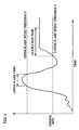
- FIG. 4is a graph illustrating engine speed profile during a starting sequence
- FIG. 5is a flow chart illustrating portions of a control algorithm for an engine starting system.
- a hybrid vehicle employing a motor generator or “MoGen” in a hybrid systemallows many new and unique forms of powertrain control. Accordingly, it is advantageous to determine the status of numerous components of a hybrid system in order to most efficiently utilize all facets of the powertrain control.
- the fuel flow to the engineis shut off to improve fuel economy. Therefore, it is desirable to have the status of the hybrid vehicle components inputted into the control system.
- a MoGen systemis implemented to enable this fuel-cutoff feature without sacrificing driveability. From a stop, upon brake-pedal release, the MoGen system creeps the vehicle forward while turning the gas engine to start it. Once the engine is running, the MoGen acts as a generator to supply the vehicle's electrical power requirements as well as recharging an electrical storage medium or battery pack. When the engine is off, the vehicle's electrical loads (fans, radio. etc.) are supported by a battery system and a DCDC converter, the MoGen also acts as a motor during fuel-off deceleration downshift to synchronize the engine and transmission speeds.
- the control systemmay be used in the environment described with reference to FIG. 1 .
- the control systemcontrols the fuel efficiency of a hybrid vehicle drive system 10 .
- Hybrid vehicle drive systemincludes a gas engine 12 , a torque converter 14 and a multi-speed automatic transmission 16 .
- the hybrid drive system 10further includes a motor generator 18 operatively connected to the front end of the engine by a direct belt or chain drive 20 for providing a drive path to a crankshaft 22 of engine 12 .
- Motor generator 18is operatively associated with a controller 24 for selectively operating motor-generator 18 during start or to produce generated power for charging an array of batteries 26 .
- An engine and transmission controller 28is associated with a brake pressure sensor 30 that directs a signal to controller 28 .
- a suitable DCDC converter 32is provided to direct higher voltage charging power from the motor generator 18 to a low voltage accessory system, during generator operation.
- the systemincludes an over-speed locking and forward speed freewheeling one-way clutch assembly as described in U.S. patent application Ser. No. 09/483,987, filed Jan. 8, 2000, the contents of which are incorporated herein by reference thereto, operatively connected between the impeller or pump of the torque converter 14 and the turbine thereof.
- the transmission 16includes known gear sets, clutches, brakes operative to provide a number of drive speed ratios between the engine 12 and a vehicle drive system 34 such as the illustrated differential 36 and drive wheels 38 and 40 with it being understood that the drive wheels can be front or rear drive wheels and that the drive system can be modified to include various forms of power transfer to and from either front or rear drive wheels or both as desired.
- Multi-speed transmissions 16are well known and as such a complete description thereof is not required for purposes of understanding the configuration and operation of the present invention.
- the motor generatorcan be mounted directly to the crankshaft between the engine and the transmission.
- the power train controllerhas an engine controller that includes a dash board or control panel indicator such as a light or a chime indicative of the hybrid system being active as shown by reference numeral 42 in FIG. 1 .
- the power train controllerincludes an engine and transmission control microprocessor 28 that is inputted with engine output speed Ne, transmission states, vehicle speed Nv, intake manifold air pressure MAP, brake sensor signal, and throttle position TP and is programmed in response to such signals to deliver fuel and engine spark to control engine acceleration and speed.
- a control systemdetermines the Degree of Hybridization of the vehicle.
- Degree of Hybridizationrelates to the level or degree to which the MoGen hybrid system interacts with or replaces, the normal functions of an internal combustion engine.
- the MoGen systemcan be used to optimize control for all internal combustion engine operational modes. Additionally, the enhanced control of charging capabilities allows a much more efficient control methodology. Therefore, in accordance with the increased control capabilities, a control system must exist to take advantage of the increased opportunities offered by the MoGen hybrid hardware.
- FIG. 2an electrical schematic of a MoGen hybrid powertrain 50 is illustrated.
- This hybrid powertrain systemuses “Excess Regen” determined through a single current-measuring device (e.g. shunt), as the main variable to manage the battery SOU (state-of-usage) and SOC (state-of-charge).
- the electrical power control system and the mechanical architecturedynamically change among four different modes of battery SOU to maintain battery SOC, enhance battery longevity, maintain vehicle driveability, and improve engine responsiveness.
- the modesare identified as follows: Excess Regen; Zero Excess Regen; MoGen Neutral; and Motoring Discharge.
- a first battery, battery B 1is chassis grounded, and an additional two batteries B 2 and B 3 are all connected in series as shown in FIG. 2 .
- the respective voltages across each battery (B 1 , B 2 and B 3 )is identified as V 1 , V 2 , and V 3 .
- a single 36V battery module with three postscan also be used, as well as a 36V module and a separate 12V module.
- a “DCDC converter” 52converts the 36V bus down to the conventional 12V to power, in parallel with B 1 and an Under Hood Junction Box 54 (UHJB).
- An alternative systemutilizes more or fewer battery modules depending on the module voltage (e.g. 2V, 6V, 8V, 12V. etc.) and can also be configured with an isolated as well as a non-isolated DCDC converter.
- module voltagee.g. 2V, 6V, 8V, 12V. etc.
- the MoGen drive systemis powered by a higher voltage (e.g. 36V nominal instead of the conventional 12V nominal system) battery pack.
- the 36V busis connected to a motor controller 56 that regulates the MoGen power.
- the battery packsees the motor controller as a load (drawing current out of the batteries).
- the MoGenis in generator mode, the battery pack sees the motor controller as a charger.
- the 36V battery packpowers the DCDC converter.
- the DCDC convertertransforms the 36V down to the conventional 12V for powering the standard automotive accessories (e.g. fans, radio, etc.).
- FIG. 2uses a non-isolated DCDC converter, thus the shunt is positioned on the high-side.
- the MoGen shaftis connected to the internal-combustion engine and the arrows indicate current flow.
- the battery SOU or mode of operation of the MoGen systemcan dynamically change among four states:
- the Excess Regencan be commanded up to a set value; if the battery pack SOC is high, the Excess Regen is tapereddown to a minimal value.
- the upper limit for Excess Regenis determined by the drivability of the vehicle: i.e. if the Excess Regen is too high, the powertrain will feel sluggish. This SOU is active:
- Zero Excess Regenis used when the batteries are fully charged. Determination of when the batteries are fully charged can be estimated from charge voltage, charge amperage, open-circuit voltage, and charge integration coupled with the Peukert relationship. In actuality, since the DCDC converter loads can be constantly fluctuating, the excess regen cannot be held to exactly zero. It is preferable to slightly overcharge than to consistently undercharge the battery pack. Thus, even when Zero Excess Regen is commanded, the system is biased toward slight Excess Regen. This SOU is active when:
- the battery SOCis full.
- the MoGenis controlled to Zero Excess Regen after the MoGen is done motoring the ICE, but before the combustion is deemed fully stabilized.
- the MoGendelivers mechanical work to the engine.
- the electrical charge flowing out of the battery pack i DCDC+Mis the sum of this MoGen motoring load i M and the DCDC converter input load i DCDC . This can occur under the following conditions:
- a control systemis employed for the initial engine crank-starting upon key up.
- the MoGen systemcan dynamically reapply electric motoring power during an engine start attempt, in addition to increasing IAC (idle-air-control) opening and slewing spark timing.
- the MoGen systemcan modulate between four states (motoring, zero excess-regen, neutral, and regen) of MoGen power during a starting flare.
- the Smart DCDC converter(U.S. patent application Ser. No. 09/659,395) does not allow battery B 1 's voltage to get under the minimum voltage required for the vehicle's computers.
- the engine speed at which fuel and spark are delivered during a startis a function of battery state-of-charge and engine coolant temperature to improve tailpipe emissions, cranking smoothness, and to reduce excessive flare above the target idle speed.
- Battery voltage balance among the modules(e.g. three for a 36V nominal system) must be within a certain range.
- FIG. 3a flow chart depicting a control algorithm 70 for determining fueling RPM and amount of engine prime pulse for the MoGen system is illustrated.
- the engine speed at which the fuel (and amount of fuel) and spark are delivered for the engine startis a function of battery SOC and engine coolant temperature (ECT).
- ECTengine coolant temperature
- the engine speed for startis adjusted to improve cranking smoothness and tailpipe emissions.
- a first decision node 72determines whether the batteries state of charge (SOC) is low (e.g. below a predetermined value), if the batteries state of charge is not low a decision node 74 determines whether the SOC is medium (e.g. below a predetermined value higher than the predetermined value of decision node 72 ).
- SOCbatteries state of charge
- decision node 74determines whether the battery SOC is greater than the predetermined value of decision node 74 a decision node 76 determines whether the engine coolant temperature (ECT is below a predetermined calibration constant representing a low value). If decision node 76 determines that the engine coolant temperature is not below the predetermined value of decision node 76 the engine firing is initiated at a high RPM (e.g. 600 rpm) without a prime pulse. This firing is represented by box 78 .
- a high RPMe.g. 600 rpm
- decision node 76determines that the engine coolant temperature is below of the predetermined calibration constant of decision node 76 the engine firing is initiated at a low RPM (e.g. 100 rpm) with a prime pulse. This firing is represented by box 80 .
- a low RPMe.g. 100 rpm
- a decision node 82determines whether the engine coolant temperature is low (e.g. below a calibration constant). If decision node 82 determines that the engine coolant temperature is below the calibration constant a decision node 82 the engine firing is initiated at a low RPM (e.g. 100 rpm) with a prime pulse. This firing is represented by box 80 .
- a low RPMe.g. 100 rpm
- a decision node 84determines whether the engine coolant temperature is at a medium temperature (e.g. below a calibration constant representing medium temperature).
- decision node 84determines that the engine coolant temperature is at the medium-range, the engine firing is initiated at a medium RPM (e.g. 400 rpm) with a minimum prime pulse. This firing is represented by box 86 .
- a medium RPMe.g. 400 rpm
- the engine firingis initiated at a medium RPM (e.g. 400 rpm) with a minimum prime pulse. This firing is represented by box 88 .
- a medium RPMe.g. 400 rpm
- decision node 72determines whether the batteries state of charge is below the calibration constant of decision node 72 (e.g. low state of charge) a decision node 90 determines whether the engine coolant temperature is also low (e.g. below a calibration constant representing a low engine coolant temperature). If so, the engine firing is initiated at a low RPM (e.g. 100 rpm) with a prime pulse. This firing is represented by box 80 .
- a low RPMe.g. 100 rpm
- a decision node 92determines whether the engine coolant temperature is in a medium range. If so, the engine firing is initiated at a low RPM (e.g. 100 rpm) with a medium prime pulse. This firing is represented by box 94 .
- a low RPMe.g. 100 rpm
- decision node 92determines that the engine coolant temperature is above the calibration constant of decision node 92 the engine firing is initiated at a low RPM (e.g. 100 rpm) with a minimal prime pulse. This firing is represented by box 96 .
- a low RPMe.g. 100 rpm
- the engine firinginitiates at a low engine speed (e.g. 100 rpm) with a prime pulse, but if the SOC is high and the ECT is medium, the engine firing can initiate at a higher engine speed without a prime pulse, thereby reducing tailpipe emissions.
- a low engine speede.g. 100 rpm
- the engine firingcan initiate at a higher engine speed without a prime pulse, thereby reducing tailpipe emissions.
- Another exampleis if the SOC is low and the ECT is high, the firing can initiate at a low rpm with a minimal prime pulse.
- the systemwill attempt to fire the engine at the lowest possible engine speed at which the combustion will not pulse the engine backwards. This ensures that the MoGen is motoring as effectively as possible.
- the MoGen motoring poweris ramped down when the engine start is deemed successful.
- An engine startis successful if both of the following are satisfied:
- the engineis firing above the Upper Flare Speed Threshold (FIG. 4) for greater than a set continuous time, Upper Flare Time.
- the engineis firing above the Lower Flare Speed Threshold (FIG. 4) for greater than a set continuous time, Stable Run Time.
- the powertrain computermonitors the engine speed flare over time. If the engine speed surpasses the Upper Flare Threshold for a set time Upper Flare Time the MoGen motoring power is ramped down to zero excess regen. If the MoGen command were stewed to higher values of excess regen, the extra retarding torque imposed on the engine crank can drag down the engine speed.
- the Upper Flare Speed Threshold and time calibrationis set as a function of engine coolant temperature. When the engine is cold, the probability of unstable combustion is higher; therefore, the required engine speed threshold and time above that threshold before MoGen motoring power is reduced and is set higher than in a warm engine scenario.
- the MoGencan first be set to neutral (negative excess regen since all the DCDC converter input power is drawn from the 36V battery bus). Setting the MoGen to neutral lets it spin freely, thus not actively contributing to the engine deceleration.
- the MoGen motoring poweris increased or reapplied to aid the combustion power to raise the engine speed back above the lower flare threshold. This is done in conjunction with increasing the IAC opening and optimizing spark timing for increased internal-combustion engine power (regardless of driver throttle command).
- the startis deemed successful if the engine speed stays above the Lower Flare Speed Threshold for a continuous time exceeding a preset value (Stable Run Time), which is a function of coolant temperature. If the engine speed droops below the Lower Flare Speed Threshold, the Stable Run Time value is reset.
- the hybrid powertrain control systemtakes over to smoothly and efficiently start the engine.
- the next engine starting sequencemust start from an ignition key position other than the “start” or “crank” position. For example, if the driver continuously holds the key in the start position (though the driver did not have to) during the unsuccessful start attempt, the key must be released back to the “run,” “accessory,” or “off” position for he starting system to make its next attempt.
- the ignition keyis removed, or turned to ACCESSORY, or OFF (i.e. not in RUN or START).
- the MoGenWhen the MoGen is spinning with the engine firing, the MoGen acts as a generator to power the DCDC converter and to charge the batteries.
- the “excess regen”is the MoGen generating power used to recharge the batteries.
- the DCDC converterconverts the 36V nominal MoGen bus voltage down to the standard 12V nominal vehicle system voltage to power the ignition system, fuel pump, transmission solenoids, etc.
- the DCDC converter outputbalances the battery state-of-charge (SOC) with the parallel-connected chassis-grounded battery (B 1 ).
- SOCbattery state-of-charge
- B 1parallel-connected chassis-grounded battery
- An exception to the battery-balancing routine during engine crankingis that the DCDC converter strives to raise its voltage output to B 1 so that its voltage stays above a set threshold (e.g. 9V). This is necessary in order to keep the powertrain computer, and thus the ignition system, active during the crank procedure.
- FIG. 5a flow chart illustrates portions of a computer algorithm for a MoGen engine starting system 100 , given a SOC and ECT. It is noted that system 100 runs simultaneously with control algorithm 70 during a starting event.
- starting system 100includes a decision node 102 that determines whether all of the conditions has been met for a starting of the hybrid vehicle to take place.
- step 104ensures that the start system has been enabled and the key has been turned to a crank position.
- a decision node 106determines whether the maximum time has been exceeded, if so the system is returned to an initial state prior to decision node 106 .
- a step 108instructs the power to the Mogen to be ramped up in order to provide cranking power to the system.
- a decision node 110determines if the anyone of the following is true: vehicle shifter out of park or neutral; ignition key position is out of a run or start position; an error (e.g. fault detection) has been detected; and in the case of a manual transmission the clutch pedal is no longer depressed or a clutch is no longer engaged, a step 112 instructs the system to abort the crank up procedure.
- a decision node 114determines whether the upper flare speed threshold (FIG. 4) has been exceeded. If the upper flare speed threshold has not been exceeded the system returns to the state indicated by decision node 106 otherwise, a decision node 116 determines whether the upper flare time has been exceeded.
- a step 118instructs the MoGen to ramp down.
- a decision node 120determines whether the starting sequence as exceeded a maximum allowable time. If so, the system returns to the state indicated by decision node 102 otherwise, a decision node 122 determines whether the lower flare speed threshold (FIG. 4) has been exceeded. If so, a decision node 124 determines whether the lower flare time has been exceeded. If so, a starting sequence is exited.
- a step 126raises the MoGen IAC, Slewand Spark. After step 126 , the system returns to the state indicated by decision node 120 .
- decision node 124determines that the lower flare time has not been exceeded the system returns to the state indicated by decision node 120 .
- FIGS. 1-5a starting system employing a Mogen control system in accordance with an exemplary embodiment of the present invention varies the electric motoring power during an engine start attempt wherein the MoGen system is capable of modulating between four states of MoGen power during a starting flare.
- the control algorithms illustrated in FIGS. 3 and 5are simultaneously utilized during a start event.
- the algorithms monitor vehicle operating conditions through a plurality of sensorssuch operating conditions include but not limited to the following: vehicle speed, engine speed, engine RPM, MoGen state of use, battery state of charge, engine cooling temperature in order to the vary the operating condition of the MoGen as well as the vehicle propulsion system during a starting event.
Landscapes
- Engineering & Computer Science (AREA)
- Chemical & Material Sciences (AREA)
- Combustion & Propulsion (AREA)
- Mechanical Engineering (AREA)
- Transportation (AREA)
- General Engineering & Computer Science (AREA)
- Automation & Control Theory (AREA)
- Hybrid Electric Vehicles (AREA)
- Control Of Vehicle Engines Or Engines For Specific Uses (AREA)
- Electric Propulsion And Braking For Vehicles (AREA)
Abstract
Description
Claims (16)
Priority Applications (3)
| Application Number | Priority Date | Filing Date | Title |
|---|---|---|---|
| US09/870,337US6612386B2 (en) | 2001-05-30 | 2001-05-30 | Apparatus and method for controlling a hybrid vehicle |
| US09/961,205US20020179348A1 (en) | 2001-05-30 | 2001-09-24 | Apparatus and method for controlling a hybrid vehicle |
| DE10222425ADE10222425B4 (en) | 2001-05-30 | 2002-05-21 | Device and method for controlling a hybrid vehicle |
Applications Claiming Priority (1)
| Application Number | Priority Date | Filing Date | Title |
|---|---|---|---|
| US09/870,337US6612386B2 (en) | 2001-05-30 | 2001-05-30 | Apparatus and method for controlling a hybrid vehicle |
Related Child Applications (1)
| Application Number | Title | Priority Date | Filing Date |
|---|---|---|---|
| US09/961,205Continuation-In-PartUS20020179348A1 (en) | 2001-05-30 | 2001-09-24 | Apparatus and method for controlling a hybrid vehicle |
Publications (2)
| Publication Number | Publication Date |
|---|---|
| US20020179347A1 US20020179347A1 (en) | 2002-12-05 |
| US6612386B2true US6612386B2 (en) | 2003-09-02 |
Family
ID=25355172
Family Applications (1)
| Application Number | Title | Priority Date | Filing Date |
|---|---|---|---|
| US09/870,337Expired - Fee RelatedUS6612386B2 (en) | 2001-05-30 | 2001-05-30 | Apparatus and method for controlling a hybrid vehicle |
Country Status (2)
| Country | Link |
|---|---|
| US (1) | US6612386B2 (en) |
| DE (1) | DE10222425B4 (en) |
Cited By (27)
| Publication number | Priority date | Publication date | Assignee | Title |
|---|---|---|---|---|
| US20020189397A1 (en)* | 2001-06-19 | 2002-12-19 | Hitachi, Ltd. | Power transmission apparatus for automobile |
| US20030048014A1 (en)* | 2001-09-13 | 2003-03-13 | Denso Corporation | Engine starter having clutch for connection to engine |
| US20040227480A1 (en)* | 2002-11-20 | 2004-11-18 | Honda Motor Co., Ltd. | Control apparatus for controlling regenerative operation of vehicle motor |
| US20050056475A1 (en)* | 2003-09-15 | 2005-03-17 | Roberts Alexander J. | Displacement on demand with regenerative braking |
| US20050134206A1 (en)* | 2003-12-22 | 2005-06-23 | Caterpillar Inc. | Motor/generator transient response system |
| US7061130B1 (en)* | 2004-02-03 | 2006-06-13 | Dana Corporation | Method of determining transition from starter to alternator function by monitoring starter/alternator motor phase voltage or current |
| US20060166783A1 (en)* | 2005-01-26 | 2006-07-27 | Goro Tamai | Engine spin-up control with natural torque smoothing |
| US20070000703A1 (en)* | 2005-06-16 | 2007-01-04 | Hughes Douglas A | Hybrid electric powertrain with anti-idle function |
| US20070029971A1 (en)* | 2005-08-02 | 2007-02-08 | Ford Global Technologies, Llc | Vehicle and method for operating a battery in a vehicle |
| US20070062745A1 (en)* | 2004-05-25 | 2007-03-22 | Bayerische Motoren Werke Aktiengsellschaft | Method for operating a hybrid motor vehicle |
| US20070099750A1 (en)* | 2005-10-31 | 2007-05-03 | Caterpillar Inc. | Power system |
| US20070210584A1 (en)* | 2006-03-10 | 2007-09-13 | Deere & Company, A Delaware Corporation | Method and system for managing an electrical output of a turbogenerator |
| US20080093851A1 (en)* | 2006-10-24 | 2008-04-24 | Denso Corporation | Method and apparatus for controlling charging operations for battery |
| US20090250272A1 (en)* | 2006-06-13 | 2009-10-08 | Toyota Jidosha Kabushiki Kaisha | Vehicle drive mechanism |
| US20100108426A1 (en)* | 2008-10-30 | 2010-05-06 | Lev Pekarsky | Electro-mechanical pump for an automatic transmission |
| US20110066352A1 (en)* | 2009-09-16 | 2011-03-17 | Gm Global Technology Operations, Inc. | System and method for engine and fuel system maintenance |
| US20110190968A1 (en)* | 2010-02-03 | 2011-08-04 | Toyota Motor Engineering & Manufacturing North America, Inc. | Method and system for more efficient operation of plug-in electric vehicles |
| US20120143447A1 (en)* | 2009-01-13 | 2012-06-07 | Allison Transmission, Inc. | Power train controller and associated memory device |
| US20130046435A1 (en)* | 2011-08-15 | 2013-02-21 | GM Global Technology Operations LLC | Method and apparatus to evaluate a starting system for an internal combustion engine |
| US8710785B2 (en) | 2007-12-18 | 2014-04-29 | Nederlandse Organisatie Voor Toegepast-Natuurwetenschappelijk Onderzoek Tno | Method of operating an electromechanical converter, a controller and a computer program product |
| US20140172216A1 (en)* | 2012-12-18 | 2014-06-19 | Mitsubishi Jidosha Kogyo Kabushiki Kaisha | Charge control device for hybrid vehicle |
| US20140343812A1 (en)* | 2013-05-14 | 2014-11-20 | GM Global Technology Operations LLC | Engine startup control systems and methods |
| US20150045999A1 (en)* | 2013-08-06 | 2015-02-12 | Honda Motor Co., Ltd. | Hybrid vehicle system and control method for enhancing startup flare control |
| US20150083079A1 (en)* | 2013-09-26 | 2015-03-26 | Ford Global Technologies, Llc | Methods and systems for selective engine starting |
| US20150166041A1 (en)* | 2013-12-13 | 2015-06-18 | Toyota Jidosha Kabushiki Kaisha | Hybrid vehicle |
| US9828965B2 (en)* | 2016-01-21 | 2017-11-28 | GM Global Technology Operations LLC | Method and apparatus to evaluate a starter motor for an internal combustion engine |
| US20180080402A1 (en)* | 2015-03-18 | 2018-03-22 | Jaguar Land Rover Limited | Vehicle control unit |
Families Citing this family (11)
| Publication number | Priority date | Publication date | Assignee | Title |
|---|---|---|---|---|
| JP2004282826A (en)* | 2003-03-13 | 2004-10-07 | Honda Motor Co Ltd | Engine driven generator |
| US7107956B2 (en)* | 2004-07-30 | 2006-09-19 | Ford Global Technologies, Llc | Vehicle and method for controlling engine start in a vehicle |
| US7723864B2 (en)* | 2005-07-26 | 2010-05-25 | Norgren, Inc. | AC-to-DC electrical switching circuit |
| US7753147B2 (en)* | 2007-01-31 | 2010-07-13 | Gm Global Technology Operations, Inc. | Vehicle drive system, power management device, and method for managing power |
| DE102009034765A1 (en) | 2009-07-25 | 2011-01-27 | Daimler Ag | Method for starting internal combustion engine of electric hybrid vehicle, involves injecting fuel into internal combustion engine, and igniting fuel with predetermined starting speed of internal combustion engine |
| JP6241438B2 (en)* | 2015-03-11 | 2017-12-06 | トヨタ自動車株式会社 | Control device for hybrid vehicle |
| KR101684543B1 (en)* | 2015-06-19 | 2016-12-20 | 현대자동차 주식회사 | System and method for driving mode control of hybrid vehicle |
| JP6521019B2 (en)* | 2017-10-03 | 2019-05-29 | マツダ株式会社 | Control device for a vehicle with multistage automatic transmission |
| KR102411583B1 (en)* | 2021-03-29 | 2022-06-22 | 주식회사 현대케피코 | Start-up method and device in case of a cam sensor error on a mild hybrid system |
| US20230242117A1 (en)* | 2022-01-31 | 2023-08-03 | Gregory Clarence Ettel | Transmission-driven generator on an electric vehicle |
| US12196145B2 (en)* | 2023-05-31 | 2025-01-14 | Fca Us Llc | Engine speed management with increased electrical power supply |
Citations (20)
| Publication number | Priority date | Publication date | Assignee | Title |
|---|---|---|---|---|
| US4269280A (en) | 1978-05-05 | 1981-05-26 | Rosen Charles L | Propulsion system for automotive vehicles |
| US4335429A (en)* | 1979-03-20 | 1982-06-15 | Daihatsu Motor Co., Ltd. | Control apparatus for engine/electric hybrid vehicle |
| US4351405A (en) | 1978-10-12 | 1982-09-28 | Hybricon Inc. | Hybrid car with electric and heat engine |
| US4438342A (en) | 1980-05-15 | 1984-03-20 | Kenyon Keith E | Novel hybrid electric vehicle |
| DE4142863A1 (en) | 1991-10-16 | 1993-04-22 | Mannesmann Ag | Trackless vehicle with hybrid drive - recovers energy during vehicle braking by switching drive motors into generator mode |
| US5249637A (en) | 1989-12-05 | 1993-10-05 | Audi Ag | Hybrid vehicle |
| US5566774A (en)* | 1992-05-15 | 1996-10-22 | Mitsubishi Jidosha Kogyo Kabushiki Kaisha | Operating method for a hybrid vehicle |
| US5568023A (en) | 1994-05-18 | 1996-10-22 | Grayer; William | Electric power train control |
| US5614809A (en)* | 1994-08-22 | 1997-03-25 | Honda Giken Kogyo Kabushiki Kaisha | Electric generation control system for hybrid vehicle |
| US5713425A (en) | 1996-01-16 | 1998-02-03 | Ford Global Technologies, Inc. | Parallel hybrid powertrain for an automotive vehicle |
| US5789881A (en) | 1995-12-27 | 1998-08-04 | Denso Corporation | Power source control apparatus for hybrid vehicles |
| US5890468A (en) | 1994-01-25 | 1999-04-06 | Komatsu Ltd. | Differential driving supercharger and method for controlling the same |
| EP0925981A2 (en) | 1997-12-26 | 1999-06-30 | Fuji Jukogyo Kabushiki Kaisha | Power transmitting system for a hybrid motor vehicle |
| US6003626A (en)* | 1995-10-05 | 1999-12-21 | Toyota Jidosha Kabushiki Kaisha | Hybrid drive system for motor vehicle, having means for inhibiting electricity generating drive mode |
| US6020697A (en) | 1997-11-14 | 2000-02-01 | Honda Giken Kogyo Kabushiki Kaisha | Hybrid vehicle |
| US6166517A (en)* | 1998-12-07 | 2000-12-26 | Honda Giken Kogyo Kabushiki Kaisha | Control system for hybrid vehicle |
| US6253127B1 (en)* | 1998-10-15 | 2001-06-26 | Nissan Motor Co., Ltd. | Engine startup control device and control method |
| US6408969B1 (en)* | 1998-03-26 | 2002-06-25 | Vibromax Bodenverdichtungsmaschinen Gmbh | Road roller |
| US6459166B2 (en)* | 2000-02-16 | 2002-10-01 | Mitsubishi Jidosha Kogyo Kabushiki Kaisha | Warm-up control device of hybrid electric vehicle |
| US6469402B2 (en)* | 2000-04-05 | 2002-10-22 | Suzuki Motor Corporation | Control apparatus for hybrid vehicle |
Family Cites Families (3)
| Publication number | Priority date | Publication date | Assignee | Title |
|---|---|---|---|---|
| US4683859A (en)* | 1984-11-09 | 1987-08-04 | Nippondenso Co., Ltd. | Apparatus for injecting fuel into internal combustion engine |
| JP3584725B2 (en)* | 1998-03-23 | 2004-11-04 | 日産自動車株式会社 | Braking force control device |
| JP4085558B2 (en)* | 1999-10-01 | 2008-05-14 | アイシン・エィ・ダブリュ株式会社 | Hybrid vehicle drive system |
- 2001
- 2001-05-30USUS09/870,337patent/US6612386B2/ennot_activeExpired - Fee Related
- 2002
- 2002-05-21DEDE10222425Apatent/DE10222425B4/ennot_activeExpired - Fee Related
Patent Citations (20)
| Publication number | Priority date | Publication date | Assignee | Title |
|---|---|---|---|---|
| US4269280A (en) | 1978-05-05 | 1981-05-26 | Rosen Charles L | Propulsion system for automotive vehicles |
| US4351405A (en) | 1978-10-12 | 1982-09-28 | Hybricon Inc. | Hybrid car with electric and heat engine |
| US4335429A (en)* | 1979-03-20 | 1982-06-15 | Daihatsu Motor Co., Ltd. | Control apparatus for engine/electric hybrid vehicle |
| US4438342A (en) | 1980-05-15 | 1984-03-20 | Kenyon Keith E | Novel hybrid electric vehicle |
| US5249637A (en) | 1989-12-05 | 1993-10-05 | Audi Ag | Hybrid vehicle |
| DE4142863A1 (en) | 1991-10-16 | 1993-04-22 | Mannesmann Ag | Trackless vehicle with hybrid drive - recovers energy during vehicle braking by switching drive motors into generator mode |
| US5566774A (en)* | 1992-05-15 | 1996-10-22 | Mitsubishi Jidosha Kogyo Kabushiki Kaisha | Operating method for a hybrid vehicle |
| US5890468A (en) | 1994-01-25 | 1999-04-06 | Komatsu Ltd. | Differential driving supercharger and method for controlling the same |
| US5568023A (en) | 1994-05-18 | 1996-10-22 | Grayer; William | Electric power train control |
| US5614809A (en)* | 1994-08-22 | 1997-03-25 | Honda Giken Kogyo Kabushiki Kaisha | Electric generation control system for hybrid vehicle |
| US6003626A (en)* | 1995-10-05 | 1999-12-21 | Toyota Jidosha Kabushiki Kaisha | Hybrid drive system for motor vehicle, having means for inhibiting electricity generating drive mode |
| US5789881A (en) | 1995-12-27 | 1998-08-04 | Denso Corporation | Power source control apparatus for hybrid vehicles |
| US5713425A (en) | 1996-01-16 | 1998-02-03 | Ford Global Technologies, Inc. | Parallel hybrid powertrain for an automotive vehicle |
| US6020697A (en) | 1997-11-14 | 2000-02-01 | Honda Giken Kogyo Kabushiki Kaisha | Hybrid vehicle |
| EP0925981A2 (en) | 1997-12-26 | 1999-06-30 | Fuji Jukogyo Kabushiki Kaisha | Power transmitting system for a hybrid motor vehicle |
| US6408969B1 (en)* | 1998-03-26 | 2002-06-25 | Vibromax Bodenverdichtungsmaschinen Gmbh | Road roller |
| US6253127B1 (en)* | 1998-10-15 | 2001-06-26 | Nissan Motor Co., Ltd. | Engine startup control device and control method |
| US6166517A (en)* | 1998-12-07 | 2000-12-26 | Honda Giken Kogyo Kabushiki Kaisha | Control system for hybrid vehicle |
| US6459166B2 (en)* | 2000-02-16 | 2002-10-01 | Mitsubishi Jidosha Kogyo Kabushiki Kaisha | Warm-up control device of hybrid electric vehicle |
| US6469402B2 (en)* | 2000-04-05 | 2002-10-22 | Suzuki Motor Corporation | Control apparatus for hybrid vehicle |
Cited By (57)
| Publication number | Priority date | Publication date | Assignee | Title |
|---|---|---|---|---|
| US7150698B2 (en)* | 2001-06-19 | 2006-12-19 | Hitachi, Ltd. | Power transmission apparatus for automobile |
| US20020189397A1 (en)* | 2001-06-19 | 2002-12-19 | Hitachi, Ltd. | Power transmission apparatus for automobile |
| US20030048014A1 (en)* | 2001-09-13 | 2003-03-13 | Denso Corporation | Engine starter having clutch for connection to engine |
| US6768215B2 (en)* | 2001-09-13 | 2004-07-27 | Denso Corporation | High rotational speed optimized engine starter having clutch connection to engine |
| US20040227480A1 (en)* | 2002-11-20 | 2004-11-18 | Honda Motor Co., Ltd. | Control apparatus for controlling regenerative operation of vehicle motor |
| US7034475B2 (en)* | 2002-11-20 | 2006-04-25 | Honda Motor Co., Ltd. | Control apparatus for controlling regenerative operation of vehicle motor |
| US20050056475A1 (en)* | 2003-09-15 | 2005-03-17 | Roberts Alexander J. | Displacement on demand with regenerative braking |
| WO2005028241A3 (en)* | 2003-09-15 | 2005-10-27 | Gen Motors Corp | Displacement on demand with regenerative braking |
| CN100450810C (en)* | 2003-09-15 | 2009-01-14 | 通用汽车公司 | Displacement on demand with regenerative braking |
| US7308959B2 (en)* | 2003-09-15 | 2007-12-18 | General Motors Corporation | Displacement on demand with regenerative braking |
| US7030580B2 (en)* | 2003-12-22 | 2006-04-18 | Caterpillar Inc. | Motor/generator transient response system |
| US20050134206A1 (en)* | 2003-12-22 | 2005-06-23 | Caterpillar Inc. | Motor/generator transient response system |
| US7061130B1 (en)* | 2004-02-03 | 2006-06-13 | Dana Corporation | Method of determining transition from starter to alternator function by monitoring starter/alternator motor phase voltage or current |
| US7513325B2 (en)* | 2004-05-25 | 2009-04-07 | Bayerische Motoren Werke Aktiengesellschaft | Method for operating a hybrid motor vehicle |
| US20070062745A1 (en)* | 2004-05-25 | 2007-03-22 | Bayerische Motoren Werke Aktiengsellschaft | Method for operating a hybrid motor vehicle |
| US20060166783A1 (en)* | 2005-01-26 | 2006-07-27 | Goro Tamai | Engine spin-up control with natural torque smoothing |
| US7220217B2 (en)* | 2005-01-26 | 2007-05-22 | General Motors Corporation | Engine spin-up control with natural torque smoothing |
| CN1810556B (en)* | 2005-01-26 | 2010-06-09 | 通用汽车公司 | Engine Acceleration Control in Natural and Steady Torque State |
| US20070000703A1 (en)* | 2005-06-16 | 2007-01-04 | Hughes Douglas A | Hybrid electric powertrain with anti-idle function |
| US7665557B2 (en)* | 2005-06-16 | 2010-02-23 | Eaton Corporation | Hybrid electric powertrain with anti-idle function |
| US20070029971A1 (en)* | 2005-08-02 | 2007-02-08 | Ford Global Technologies, Llc | Vehicle and method for operating a battery in a vehicle |
| US7573241B2 (en) | 2005-08-02 | 2009-08-11 | Ford Global Technologies, Llc | Vehicle having a battery with multiple cells and method for operating such a battery |
| US20070099750A1 (en)* | 2005-10-31 | 2007-05-03 | Caterpillar Inc. | Power system |
| US7344472B2 (en) | 2005-10-31 | 2008-03-18 | Caterpillar Inc. | Power system |
| US7781904B2 (en) | 2006-03-10 | 2010-08-24 | Deere & Company | Method and system for managing an electrical output of a turbogenerator |
| US7541687B2 (en)* | 2006-03-10 | 2009-06-02 | Deere & Company | Method and system for managing an electrical output of a turbogenerator |
| US20090224541A1 (en)* | 2006-03-10 | 2009-09-10 | Ronnie Dean Stahlhut | Method and system for managing an electrical output of a turbogenerator |
| US20070210584A1 (en)* | 2006-03-10 | 2007-09-13 | Deere & Company, A Delaware Corporation | Method and system for managing an electrical output of a turbogenerator |
| US20090250272A1 (en)* | 2006-06-13 | 2009-10-08 | Toyota Jidosha Kabushiki Kaisha | Vehicle drive mechanism |
| US8058849B2 (en)* | 2006-06-13 | 2011-11-15 | Toyota Jidosha Kabushiki Kaisha | Vehicle drive mechanism |
| US7531909B2 (en)* | 2006-10-24 | 2009-05-12 | Denso Corporation | Method and apparatus for controlling charging operations for battery |
| US20080093851A1 (en)* | 2006-10-24 | 2008-04-24 | Denso Corporation | Method and apparatus for controlling charging operations for battery |
| US8710785B2 (en) | 2007-12-18 | 2014-04-29 | Nederlandse Organisatie Voor Toegepast-Natuurwetenschappelijk Onderzoek Tno | Method of operating an electromechanical converter, a controller and a computer program product |
| US8104555B2 (en) | 2008-10-30 | 2012-01-31 | Ford Global Technologies, Llc | Electro-mechanical pump for an automatic transmission |
| US20100108426A1 (en)* | 2008-10-30 | 2010-05-06 | Lev Pekarsky | Electro-mechanical pump for an automatic transmission |
| US9216744B2 (en)* | 2009-01-13 | 2015-12-22 | Allison Transmission, Inc. | Power train controller and associated memory device |
| US20120143447A1 (en)* | 2009-01-13 | 2012-06-07 | Allison Transmission, Inc. | Power train controller and associated memory device |
| US9970532B2 (en) | 2009-01-13 | 2018-05-15 | Allison Transmission, Inc. | Power train controller and associated memory device |
| US20110066352A1 (en)* | 2009-09-16 | 2011-03-17 | Gm Global Technology Operations, Inc. | System and method for engine and fuel system maintenance |
| US8768599B2 (en)* | 2009-09-16 | 2014-07-01 | GM Global Technology Operations LLC | System and method for engine and fuel system maintenance |
| US20110190968A1 (en)* | 2010-02-03 | 2011-08-04 | Toyota Motor Engineering & Manufacturing North America, Inc. | Method and system for more efficient operation of plug-in electric vehicles |
| US8855840B2 (en) | 2010-02-03 | 2014-10-07 | Toyota Motor Engineering & Manufacturing North America, Inc. | Method and system for more efficient operation of plug-in electric vehicles |
| US20130046435A1 (en)* | 2011-08-15 | 2013-02-21 | GM Global Technology Operations LLC | Method and apparatus to evaluate a starting system for an internal combustion engine |
| US8818611B2 (en)* | 2011-08-15 | 2014-08-26 | GM Global Technology Operations LLC | Method and apparatus to evaluate a starting system for an internal combustion engine |
| US9573580B2 (en)* | 2012-12-18 | 2017-02-21 | Mitsubishi Jidosha Kogyo Kabushiki Kaisha | Charge control device for hybrid vehicle |
| US20140172216A1 (en)* | 2012-12-18 | 2014-06-19 | Mitsubishi Jidosha Kogyo Kabushiki Kaisha | Charge control device for hybrid vehicle |
| US9115684B2 (en)* | 2013-05-14 | 2015-08-25 | GM Global Technology Operations LLC | Engine startup control systems and methods |
| US20140343812A1 (en)* | 2013-05-14 | 2014-11-20 | GM Global Technology Operations LLC | Engine startup control systems and methods |
| US9102321B2 (en)* | 2013-08-06 | 2015-08-11 | Honda Motor Co., Ltd. | Hybrid vehicle system and control method for enhancing startup flare control |
| US20150045999A1 (en)* | 2013-08-06 | 2015-02-12 | Honda Motor Co., Ltd. | Hybrid vehicle system and control method for enhancing startup flare control |
| US20150083079A1 (en)* | 2013-09-26 | 2015-03-26 | Ford Global Technologies, Llc | Methods and systems for selective engine starting |
| US9631595B2 (en)* | 2013-09-26 | 2017-04-25 | Ford Global Technologies, Llc | Methods and systems for selective engine starting |
| US20150166041A1 (en)* | 2013-12-13 | 2015-06-18 | Toyota Jidosha Kabushiki Kaisha | Hybrid vehicle |
| US9783184B2 (en)* | 2013-12-13 | 2017-10-10 | Toyota Jidosha Kabushiki Kaisha | Hybrid vehicle which supplies electric power from an external power source to a rotary electric machine |
| US20180080402A1 (en)* | 2015-03-18 | 2018-03-22 | Jaguar Land Rover Limited | Vehicle control unit |
| US10473048B2 (en)* | 2015-03-18 | 2019-11-12 | Jaguar Land Rover Limited | Vehicle control unit |
| US9828965B2 (en)* | 2016-01-21 | 2017-11-28 | GM Global Technology Operations LLC | Method and apparatus to evaluate a starter motor for an internal combustion engine |
Also Published As
| Publication number | Publication date |
|---|---|
| DE10222425A1 (en) | 2002-12-12 |
| US20020179347A1 (en) | 2002-12-05 |
| DE10222425B4 (en) | 2007-01-11 |
Similar Documents
| Publication | Publication Date | Title |
|---|---|---|
| US6612386B2 (en) | Apparatus and method for controlling a hybrid vehicle | |
| US20020179348A1 (en) | Apparatus and method for controlling a hybrid vehicle | |
| US6314346B1 (en) | Control system for hybrid vehicle | |
| US12168434B2 (en) | Hybrid vehicle engine start/stop system | |
| US6424053B1 (en) | Control apparatus for hybrid vehicle | |
| US9150219B2 (en) | Hybrid electric vehicle and method of starting engine | |
| US6262491B1 (en) | Control system for hybrid vehicle | |
| US10071724B2 (en) | Regenerative torque limit control | |
| US8136617B2 (en) | Power output apparatus and hybrid vehicle equipped with the same | |
| US9428178B2 (en) | Vehicle battery power transfer limit management system and method | |
| US20230083854A1 (en) | Hybrid vehicle engine idling control | |
| US6956298B2 (en) | Control apparatus for hybrid vehicle | |
| US11225244B2 (en) | Hybrid vehicle engine start and shift control strategy | |
| US6740987B2 (en) | Control device for hybrid vehicle | |
| US6570266B1 (en) | Control apparatus for hybrid vehicle | |
| US7467033B2 (en) | Control method for a vehicle powertrain with protection against low load conditions | |
| US20190283730A1 (en) | Control system for hybrid vehicle | |
| US11242834B1 (en) | Belt-integrated-starter-generator-assisted engine shutdown | |
| US10131342B2 (en) | Engine friction model adaptation | |
| US7243011B2 (en) | Hybrid transmission launch algorithm | |
| US7229381B2 (en) | Method for controlling engine starts for a vehicle powertrain | |
| JP7740215B2 (en) | Hybrid vehicle charging control device | |
| US20180244265A1 (en) | Autonomous motor control during loss of motor communications | |
| Tamai et al. | Saturn engine stop-start system with an automatic transmission | |
| US6717378B2 (en) | Motor output control system and method for hybrid vehicle |
Legal Events
| Date | Code | Title | Description |
|---|---|---|---|
| AS | Assignment | Owner name:GENERAL MOTORS CORPORATION, MICHIGAN Free format text:ASSIGNMENT OF ASSIGNORS INTEREST;ASSIGNORS:TAMAI, GORO;ALDRICH,III, WILLIAM LEONARD;HOANG, TONY T.;AND OTHERS;REEL/FRAME:012127/0545 Effective date:20010815 | |
| FPAY | Fee payment | Year of fee payment:4 | |
| AS | Assignment | Owner name:GM GLOBAL TECHNOLOGY OPERATIONS, INC., MICHIGAN Free format text:ASSIGNMENT OF ASSIGNORS INTEREST;ASSIGNOR:GENERAL MOTORS CORPORATION;REEL/FRAME:022117/0022 Effective date:20050119 Owner name:GM GLOBAL TECHNOLOGY OPERATIONS, INC.,MICHIGAN Free format text:ASSIGNMENT OF ASSIGNORS INTEREST;ASSIGNOR:GENERAL MOTORS CORPORATION;REEL/FRAME:022117/0022 Effective date:20050119 | |
| AS | Assignment | Owner name:UNITED STATES DEPARTMENT OF THE TREASURY, DISTRICT Free format text:SECURITY AGREEMENT;ASSIGNOR:GM GLOBAL TECHNOLOGY OPERATIONS, INC.;REEL/FRAME:022201/0501 Effective date:20081231 | |
| AS | Assignment | Owner name:CITICORP USA, INC. AS AGENT FOR BANK PRIORITY SECU Free format text:SECURITY AGREEMENT;ASSIGNOR:GM GLOBAL TECHNOLOGY OPERATIONS, INC.;REEL/FRAME:022556/0013 Effective date:20090409 Owner name:CITICORP USA, INC. AS AGENT FOR HEDGE PRIORITY SEC Free format text:SECURITY AGREEMENT;ASSIGNOR:GM GLOBAL TECHNOLOGY OPERATIONS, INC.;REEL/FRAME:022556/0013 Effective date:20090409 | |
| AS | Assignment | Owner name:GM GLOBAL TECHNOLOGY OPERATIONS, INC., MICHIGAN Free format text:RELEASE BY SECURED PARTY;ASSIGNOR:UNITED STATES DEPARTMENT OF THE TREASURY;REEL/FRAME:023238/0015 Effective date:20090709 | |
| XAS | Not any more in us assignment database | Free format text:RELEASE BY SECURED PARTY;ASSIGNOR:UNITED STATES DEPARTMENT OF THE TREASURY;REEL/FRAME:023124/0383 | |
| AS | Assignment | Owner name:GM GLOBAL TECHNOLOGY OPERATIONS, INC., MICHIGAN Free format text:RELEASE BY SECURED PARTY;ASSIGNORS:CITICORP USA, INC. AS AGENT FOR BANK PRIORITY SECURED PARTIES;CITICORP USA, INC. AS AGENT FOR HEDGE PRIORITY SECURED PARTIES;REEL/FRAME:023127/0326 Effective date:20090814 | |
| AS | Assignment | Owner name:UNITED STATES DEPARTMENT OF THE TREASURY, DISTRICT Free format text:SECURITY AGREEMENT;ASSIGNOR:GM GLOBAL TECHNOLOGY OPERATIONS, INC.;REEL/FRAME:023155/0922 Effective date:20090710 | |
| AS | Assignment | Owner name:UAW RETIREE MEDICAL BENEFITS TRUST, MICHIGAN Free format text:SECURITY AGREEMENT;ASSIGNOR:GM GLOBAL TECHNOLOGY OPERATIONS, INC.;REEL/FRAME:023161/0864 Effective date:20090710 | |
| AS | Assignment | Owner name:GM GLOBAL TECHNOLOGY OPERATIONS, INC., MICHIGAN Free format text:RELEASE BY SECURED PARTY;ASSIGNOR:UAW RETIREE MEDICAL BENEFITS TRUST;REEL/FRAME:025311/0680 Effective date:20101026 Owner name:GM GLOBAL TECHNOLOGY OPERATIONS, INC., MICHIGAN Free format text:RELEASE BY SECURED PARTY;ASSIGNOR:UNITED STATES DEPARTMENT OF THE TREASURY;REEL/FRAME:025245/0273 Effective date:20100420 | |
| AS | Assignment | Owner name:WILMINGTON TRUST COMPANY, DELAWARE Free format text:SECURITY AGREEMENT;ASSIGNOR:GM GLOBAL TECHNOLOGY OPERATIONS, INC.;REEL/FRAME:025327/0222 Effective date:20101027 | |
| AS | Assignment | Owner name:GM GLOBAL TECHNOLOGY OPERATIONS LLC, MICHIGAN Free format text:CHANGE OF NAME;ASSIGNOR:GM GLOBAL TECHNOLOGY OPERATIONS, INC.;REEL/FRAME:025780/0795 Effective date:20101202 | |
| FPAY | Fee payment | Year of fee payment:8 | |
| REMI | Maintenance fee reminder mailed | ||
| LAPS | Lapse for failure to pay maintenance fees | ||
| STCH | Information on status: patent discontinuation | Free format text:PATENT EXPIRED DUE TO NONPAYMENT OF MAINTENANCE FEES UNDER 37 CFR 1.362 | |
| FP | Lapsed due to failure to pay maintenance fee | Effective date:20150902 |