US6612143B1 - Robot and method for bending orthodontic archwires and other medical devices - Google Patents
Robot and method for bending orthodontic archwires and other medical devicesDownload PDFInfo
- Publication number
- US6612143B1 US6612143B1US09/834,967US83496701AUS6612143B1US 6612143 B1US6612143 B1US 6612143B1US 83496701 AUS83496701 AUS 83496701AUS 6612143 B1US6612143 B1US 6612143B1
- Authority
- US
- United States
- Prior art keywords
- wire
- gripping tool
- gripping
- appliance
- bending
- Prior art date
- Legal status (The legal status is an assumption and is not a legal conclusion. Google has not performed a legal analysis and makes no representation as to the accuracy of the status listed.)
- Expired - Lifetime
Links
Images


Classifications
- A—HUMAN NECESSITIES
- A61—MEDICAL OR VETERINARY SCIENCE; HYGIENE
- A61C—DENTISTRY; APPARATUS OR METHODS FOR ORAL OR DENTAL HYGIENE
- A61C7/00—Orthodontics, i.e. obtaining or maintaining the desired position of teeth, e.g. by straightening, evening, regulating, separating, or by correcting malocclusions
- A61C7/02—Tools for manipulating or working with an orthodontic appliance
- A61C7/04—Tools for manipulating or working with an orthodontic appliance plier-type, e.g. pincers
- A—HUMAN NECESSITIES
- A61—MEDICAL OR VETERINARY SCIENCE; HYGIENE
- A61C—DENTISTRY; APPARATUS OR METHODS FOR ORAL OR DENTAL HYGIENE
- A61C7/00—Orthodontics, i.e. obtaining or maintaining the desired position of teeth, e.g. by straightening, evening, regulating, separating, or by correcting malocclusions
- A61C7/12—Brackets; Arch wires; Combinations thereof; Accessories therefor
- A61C7/20—Arch wires
- B—PERFORMING OPERATIONS; TRANSPORTING
- B21—MECHANICAL METAL-WORKING WITHOUT ESSENTIALLY REMOVING MATERIAL; PUNCHING METAL
- B21F—WORKING OR PROCESSING OF METAL WIRE
- B21F1/00—Bending wire other than coiling; Straightening wire
- B—PERFORMING OPERATIONS; TRANSPORTING
- B21—MECHANICAL METAL-WORKING WITHOUT ESSENTIALLY REMOVING MATERIAL; PUNCHING METAL
- B21F—WORKING OR PROCESSING OF METAL WIRE
- B21F23/00—Feeding wire in wire-working machines or apparatus
- B21F23/005—Feeding discrete lengths of wire or rod
- B—PERFORMING OPERATIONS; TRANSPORTING
- B21—MECHANICAL METAL-WORKING WITHOUT ESSENTIALLY REMOVING MATERIAL; PUNCHING METAL
- B21F—WORKING OR PROCESSING OF METAL WIRE
- B21F45/00—Wire-working in the manufacture of other particular articles
- B—PERFORMING OPERATIONS; TRANSPORTING
- B21—MECHANICAL METAL-WORKING WITHOUT ESSENTIALLY REMOVING MATERIAL; PUNCHING METAL
- B21F—WORKING OR PROCESSING OF METAL WIRE
- B21F45/00—Wire-working in the manufacture of other particular articles
- B21F45/008—Wire-working in the manufacture of other particular articles of medical instruments, e.g. stents, corneal rings
- B—PERFORMING OPERATIONS; TRANSPORTING
- B25—HAND TOOLS; PORTABLE POWER-DRIVEN TOOLS; MANIPULATORS
- B25J—MANIPULATORS; CHAMBERS PROVIDED WITH MANIPULATION DEVICES
- B25J11/00—Manipulators not otherwise provided for
- B—PERFORMING OPERATIONS; TRANSPORTING
- B33—ADDITIVE MANUFACTURING TECHNOLOGY
- B33Y—ADDITIVE MANUFACTURING, i.e. MANUFACTURING OF THREE-DIMENSIONAL [3-D] OBJECTS BY ADDITIVE DEPOSITION, ADDITIVE AGGLOMERATION OR ADDITIVE LAYERING, e.g. BY 3-D PRINTING, STEREOLITHOGRAPHY OR SELECTIVE LASER SINTERING
- B33Y50/00—Data acquisition or data processing for additive manufacturing
- B—PERFORMING OPERATIONS; TRANSPORTING
- B33—ADDITIVE MANUFACTURING TECHNOLOGY
- B33Y—ADDITIVE MANUFACTURING, i.e. MANUFACTURING OF THREE-DIMENSIONAL [3-D] OBJECTS BY ADDITIVE DEPOSITION, ADDITIVE AGGLOMERATION OR ADDITIVE LAYERING, e.g. BY 3-D PRINTING, STEREOLITHOGRAPHY OR SELECTIVE LASER SINTERING
- B33Y80/00—Products made by additive manufacturing
- G—PHYSICS
- G16—INFORMATION AND COMMUNICATION TECHNOLOGY [ICT] SPECIALLY ADAPTED FOR SPECIFIC APPLICATION FIELDS
- G16H—HEALTHCARE INFORMATICS, i.e. INFORMATION AND COMMUNICATION TECHNOLOGY [ICT] SPECIALLY ADAPTED FOR THE HANDLING OR PROCESSING OF MEDICAL OR HEALTHCARE DATA
- G16H30/00—ICT specially adapted for the handling or processing of medical images
- G16H30/40—ICT specially adapted for the handling or processing of medical images for processing medical images, e.g. editing
- A—HUMAN NECESSITIES
- A61—MEDICAL OR VETERINARY SCIENCE; HYGIENE
- A61C—DENTISTRY; APPARATUS OR METHODS FOR ORAL OR DENTAL HYGIENE
- A61C7/00—Orthodontics, i.e. obtaining or maintaining the desired position of teeth, e.g. by straightening, evening, regulating, separating, or by correcting malocclusions
- A61C7/002—Orthodontic computer assisted systems
- A—HUMAN NECESSITIES
- A61—MEDICAL OR VETERINARY SCIENCE; HYGIENE
- A61C—DENTISTRY; APPARATUS OR METHODS FOR ORAL OR DENTAL HYGIENE
- A61C7/00—Orthodontics, i.e. obtaining or maintaining the desired position of teeth, e.g. by straightening, evening, regulating, separating, or by correcting malocclusions
- A61C7/12—Brackets; Arch wires; Combinations thereof; Accessories therefor
- A61C7/28—Securing arch wire to bracket
Definitions
- This inventionrelates to a robot and method for automatically bending orthodontic archwires, retainers, or other orthodontic or medical devices into a particular shape.
- a patient suffering from a malocclusionis treated by affixing brackets to the surface of the teeth and installing an archwire in the slots of the brackets.
- the archwire and bracketsare designed to generated a customized force system that applies forces to teeth, by which individual teeth are moved relative to surrounding anatomical structures into a desired occlusion.
- There are two approaches to designing an appropriate force system for a patientOne is based on a flat archwire and customized brackets, e.g., Andreiko et al., U.S. Pat. No. 5,447,432.
- the otheris based on off-the shelf brackets and designing a customized archwire that has complex bends designed to move or rotate the teeth in the desired direction.
- the latter approachhas required manual bending of the archwire by the orthodontist.
- the design of the '860 patentalso has other shortcomings: it provides no means for measuring forces imparted by the wire since one end of the wire is free and the wire is gripped immediately below the bending point.
- the robothad no effective feedback mechanism for detecting how the wire in fact was bent after a particular bending or twisting operation was performed.
- As the free end of the wireis not constrained or held in any manner, there is no ready way to heat the wire as it is being bent in order to fix the shape of the bend in a wire made from a shape memory material. Consequently, shape memory alloy wires made with the '860 patent were subject to a separate heating treatment in a separate thermal device.
- the present inventionpresents a substantial improvement to the robot of the '860 patent.
- the inventionalso provides for much greater flexibility in the design and manufacture of archwires than that disclosed by the Andreiko et al. patent.
- the present inventionenables the manufacture of custom, highly accurate orthodontic archwires.
- Such wiresare ideally suited to an archwire-based orthodontic treatment regime based on standard, off-the-shelf brackets.
- the inventionis also readily adaptable to bending other medical devices, including implants such bone fixation plates, prostheses, orthotic devices, and even surgical tools.
- a bending apparatus or machinefor bending an orthodontic appliance, such as a retainer or archwire, into a desired configuration. While the orthodontic device is described as being an archwire in the illustrated embodiment, other types of medical devices are contemplated as the type of article capable of being bent by the robot. Examples of such medical devices are prostheses, orthotic devices, implants, fixation plates, spectacle frames, and surgical devices such as a reamer for root canals.
- the bending apparatus or machinemay take the form of a robot mounted to a base or table support surface.
- a first gripper toolis provided. This tool can either be fixed with respect to the base or may be incorporated into a moveable arm.
- the first gripping toolhas a first gripping structure for holding the archwire or other medical device.
- the bending apparatusincludes a moveable arm having a proximal portion mounted to the base a distance away from the first gripper tool and a free distal end portion.
- the moveable armis constructed such that the free distal portion of the moveable arm is capable of independent movement relative to the first gripper tool along at least one translation axis and about at least one rotation axis.
- the moveable armhas a set of joints which allows the distal end of the arm to move in 6 degrees of freedom—orthogonal translational axes and 3 orthogonal rotational axes.
- degrees of freedomorthogonal translational axes and 3 orthogonal rotational axes.
- a lesser number of degrees of freedommay be appropriate, reducing the cost and complexity of the bending apparatus.
- a second gripping toolis mounted to the distal portion of the moveable arm.
- the second gripping toolhas a gripping structure for gripping the archwire.
- the archwireis gripped by the first and second gripping tools, with the second, moveable gripping tool capable of motion relative to the first gripping tool along at least one translational axis and at least one rotational axis.
- the robotfurther includes a control system operative of the moveable arm and the first and second gripping tools so as to cause the first and second gripping tools to grip the archwire while the gripping tools are separated from each other and to cause the second gripping tool to move about at least one of the rotational axis and translation axis to thereby bend the archwire a desired amount.
- the control systemreads an input file containing information as to the shape of the archwire (or location of bending points along the wire) and responsively operates the moveable arm and first and second gripping tools to form a series of bends and/or twists in the archwire.
- Orthodontic archwires and other medical devicesmay have elastic properties such that when a certain amount of force is applied to the workpiece, it returns to its original configuration at least to some degree. What this means is that when a certain bend is formed in the wire, say a 10 degree bend, the wire may take a shape of an 8 degree bend due to this elastic property. Hence, some overbending of the archwire may be needed to account for this elastic deformation. Solutions for overbending wire are provided.
- One methodis a force-based approach.
- the robotcomprises a force sensor system for detecting forces generated by the wire after the wire has been bent by the first and second gripping tools. Depending on the direction and magnitude of the detected forces, additional bends are formed in the wire. The proper bend in the wire is deemed to exist when the wire, at its designed shape, exhibits zero or substantially zero forces.
- An alternative approach to overbendingis based on deformation.
- the wireis bent, the wire is released from the moveable gripping tool and a measurement is made of the wire's shape, the wire is bent some more (assuming more bending is required), the wire is released again, and the process continues until the resulting configuration is the one specified by the input file.
- a camera or other optical techniquecan be used to measure the shape of the wire.
- force sensorscan be used to determine the actual bend in the wire (by moving the moveable gripper holding the wire to the position where no forces are measured), and a measurement is taken to indicate what additional bends, if any, are needed to result in the desired configuration.
- a database of overbending informationcan be acquired as the robot bends wires.
- This database of overbending informationcan be used by artificial intelligence programs to derive a relationship between overbending and desired bends, for a particular archwire material. It may be possible to overbend wires in a single step, that is without requiring a lot of intermediate bending steps, based on this database of information, or based on a derived relationship between overbending and resulting wire shape.
- the robotincludes a heating system to apply heat to the archwire or other workpiece while it is in the bent condition and/or during bending.
- a current-based resistive heating system and heated grippersare used in the illustrated embodiment. This system allows shape memory alloys to be bent by the robot and the acquired bends retained in the wire material. Other heating systems are possible depending on the nature of the device being bent.
- the robotis part of an archwire manufacturing system including a magazine containing a plurality of straight archwires.
- the magazineholds the archwires such that they are spaced from each other so as to enable the robot to grip an individual one of the archwires.
- Several different magazine designsare proposed. After the robot has formed the archwire, the archwire is placed at a finish location. A conveyor system carries the finished archwire from the finish location to a labeling and packaging station. The wires are individually labeled and packaged. Alternatively, pairs of wires could be labeled as corresponding to a single patient and packaged together.
- a gripping tool for a bending robotincludes a pair of opposing gripping fingers moveable between open and closed positions, and a force system coupled to the gripping fingers for detecting forces imparted by a workpiece such as an archwire or other medical device after a bend has been placed in the workpiece.
- the force systemcan be used to measure resulting forces after a certain bend has been placed in the wire, and the measurements used to indicate additional bending steps to yield the required configuration taking into account the need for overbending.
- a method for bending an orthodontic archwire in a bending robotincludes the steps of
- the moveable gripping tool and first gripping toolcan cooperate to place a series of bends in the archwire. It has been found that the movement called for by step f) should be performed such that a constant distance, equal to the length of archwire pulled through the fixed gripping tool in step d) is maintained between the fixed gripping tool and the moveable gripping tool. This distance should be maintained in order to avoid applying tension or compression to the wire. Since the moveable gripping tool is moving potential in three dimensions during the bending, the distance that needs to be maintained is measured along the length of the archwire. The same principle holds true for bending other types of devices.
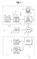
- FIG. 1is an illustration of an orthodontic care system incorporating a hand-held scanner system and an archwire manufacturing system in accordance with a representative embodiment of the invention.
- the hand-held scanneris used by the orthodontist to acquire three-dimensional information of the dentition and associated anatomical structures of a patient and provide a base of information to plan treatment for the patient.
- the archwire manufacturing systemincludes a wire bending robot to manufacture customized orthodontic archwires for shipment to the clinic.
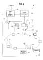
- FIG. 2is a schematic representation of an archwire manufacturing system shown in FIG. 1;
- FIG. 2Ais a block diagram of the system.
- FIG. 3is a perspective view of a moveable robot arm used in the manufacturing system in FIG. 2; in FIG. 3 the gripping tool at the distal end of the arm is omitted for sake of clarity to show the various other aspects of the arm.
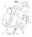
- FIG. 4is perspective view of the robot arm of FIG. 3, showing the movement of one of the arm joints and the corresponding motion of the arm.
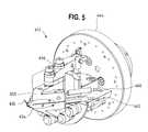
- FIG. 5is a detailed perspective view of the gripping tool that is mounted to the distal end of the moveable robot arm of FIG. 3 and FIG. 4 .
- FIG. 6is a perspective view of the fixed gripping tool of FIG. 2 and the gripping tool of FIG. 5, in which an orthodontic archwire is gripped by the tools.
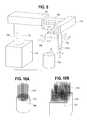
- FIG. 7is a perspective view of a magazine of FIG. 2 that holds a plurality of straight archwires.
- FIG. 8is a detailed perspective view of the moveable gripping tool grasping one of the archwires from the magazine of FIG. 7 .
- FIG. 9is a perspective view of an alternative arrangement of a moveable robot arm.
- FIGS. 10A and 10Bare perspective views of alternative magazine constructions to the magazine of FIG. 7 .
- FIG. 11is a schematic illustration of a conveyor system that carries archwires to the robot arm of FIG. 2 .
- FIG. 12is a diagram illustrating the robot software as it relates to the production flow in producing orthodontic archwires.
- FIG. 13is a simplified illustration of a set of teeth showing the origin of a coordinate system that is used to calculate bracket location for a set of brackets, in three dimensions, for a patient.
- the bracket location for the teeth in a target situationdetermines the shape of an orthodontic archwire.
- FIG. 14is an illustration showing the vectors drawn from the origin of the coordinate system to the center of the brackets.
- FIG. 15is a perspective view of an orthodontic bracket.
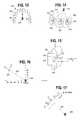
- FIG. 16is an illustration of a vector drawn from the origin of the coordinate system to the bracket, a normal vector N perpendicular to the slot surface of the bracket, and a tangential vector T extending in the direction of the slot of the bracket.
- FIG. 17shows the normal vector Y for a particular bracket, the tangential vector X, the tangential distance T d and antitangential distance AT d .
- FIG. 18shows in matrix form the values for an individual bracket which describe the location of the bracket and its orientation, which are used to generate the commands for the robot to form the orthodontic archwire.
- FIG. 19is an illustration of a set of points P 1 , P 2 , P 3 , . . . PN which represent a set of bending points associated with individual brackets for a patient in a target situation.
- the location of the points in the three-dimensional coordinate systemis known.
- FIG. 20is an illustration of a section of wire between points P 1 and P 4 in which a bend is placed between points P 2 and P 3 .
- FIG. 20Ais an illustration of four points and a curve defined by a Bezier spline, a technique used to calculate the shape of the bend in the wire between points P 2 and P 3 in FIG. 20 .
- FIG. 20Bis a flow chart of an algorithm to calculate the Bezier spline of FIG. 20 A and the length of the curve.
- FIG. 21is a graph of force as a function of deflection for a workpiece such as a wire.
- the graphillustrates that that when a certain amount of force, F 1 , is applied to the workpiece and then released, a deflection D 2 results.
- F 1force
- D 2the amount of remaining deflection
- FIG. 22is an illustration of the stresses found in a wire when it is bent.
- FIG. 23is an elevational view of the gripping fingers of the fixed gripping tool of FIG. 6, showing the origin of a coordinate system used by the robot in bending wire.
- FIG. 24is a top view of the gripping fingers of FIG. 23 .
- FIG. 25is flowchart illustrating a deformation-controlled overbending procedure, which may be used to compensate for the elastic properties of the wire demonstrated by FIG. 21 .
- FIG. 26is an illustration showing the overbending method set forth in FIG. 25 .
- FIGS. 27A-27Eare a series of schematic drawings of the fixed and moveable gripping tools of FIG. 6, showing how they moved relative to each other and grip and release the archwire to place the archwire in position to form a bend between points P 2 and P 3 of FIG. 19 .
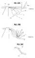
- FIG. 28is a schematic illustration showing how the movable gripping tool bends an archwire while maintaining a constant distance from the fixed gripping tool.
- FIGS. 29A-29Cillustrate how a bend may be formed in a series of steps.
- FIGS. 30A-30Dare a series of schematic drawings of the fixed and moveable gripping tools of FIG. 6, showing how they move relative to each other to place the archwire in position to form a bend between points P 4 and P 5 .
- FIG. 31is an illustration of the points defining a portion of an archwire, and illustrating a technique for placing bends in wires where a substantial distance exists between the straight wire segments.
- FIG. 32is an illustration of a portion of an archwire showing a bend formed therein to increase the forces applied by the wire when the wire has nearly straightened out, e.g., near the end of treatment.
- FIG. 33shows the wire segment of FIG. 32 installed between two teeth.
- FIGS. 34shows a wire with a loop in the wire.
- FIGS. 35A-35Billustrate one possible method of forming the loop in the wire of FIG. 34 .
- FIG. 1is an illustration of an orthodontic care system 10 incorporating a hand-held scanner system 12 .
- the scanner system 12includes a hand-held scanner 14 that is used by the orthodontist to acquire three-dimensional information of the dentition and associated anatomical structures of a patient.
- the imagesare processed in a scanning node or workstation 16 having a central processing unit, such as a general-purpose computer.
- the scanning node 16either alone or in combination with a back-office server 28 , generates a three-dimensional computer model 18 of the dentition and provides the orthodontist with a base of information to plan treatment for the patient.
- the model 18is displayed to the user on a monitor 20 connected to the scanning node 16 .
- the orthodontic care systemconsists of a plurality of orthodontic clinics 22 which are linked via the Internet or other suitable communications medium 24 (such as the public switched telephone network, cable network, etc.) to a precision appliance service center 26 .
- Each clinic 22has a back office server work station 28 having its own user interface, including a monitor 30 .
- the back office server 28executes an orthodontic treatment planning software program.
- the softwareobtains the three-dimensional digital data of the patient's teeth from the scanning node and displays the model 18 for the orthodontist.
- the treatment planning softwareincludes features to enable the orthodontist to manipulate the model 18 to plan treatment for the patient. For example, the orthodontist can select an archform for the teeth and manipulate individual tooth positions relative to the archform to arrive at a desired or target situation for the patient.
- the softwaremoves the virtual teeth in accordance with the selections of the orthodontist.
- the softwarealso allows the orthodontist to selectively place virtual brackets on the tooth models and design a customized archwire for the patient given the selected bracket position.
- digital information regarding the patient, the malocclusion, and a desired treatment plan for the patientare sent over the communications medium to the appliance service center 26 .
- a customized orthodontic archwire and a device for placement of the brackets on the teeth at the selected locationis manufactured at the service center and shipped to the clinic 22 .
- the precision appliance service center 26includes a central server 32 , an archwire manufacturing system 34 and a bracket placement manufacturing system 36 .
- the details of the scanning system per seare not particularly relevant to the wire bending features of the invention and are therefore omitted from the present discussion for sake of brevity except to the extent relevant to the present invention.
- the interested readeris directed to the patent application of Rudger Rubbert et al., filed Apr. 13, 2001, entitled INTERACTIVE AND ARCHWIRE-BASED ORTHODONTIC CARE SYSTEM BASED ON INTRA-ORAL SCANNING OF TEETH, Ser. No.
- FIG. 2is a schematic representation of a presently preferred archwire manufacturing system 34 shown in FIG. 1 .
- the key aspects of the system 34are shown in block diagram form in FIG. 2 A.
- the system 34includes a control system for controlling the operation of a wire bending robot 604 .
- the control system in the illustrated embodimentcomprises a general purpose computer 600 running a bending program and a robot controller 602 .
- the computer 600receives an input file from the precision appliance service center computer that contains information as to the location of bracket slots in three dimensions, when the teeth are in a target situation.
- the computer 600supplies the robot controller 602 with wire position information corresponding to points along the wire where bends need to be made. This information is translated by the controller 602 into motion commands for the wire bending robot 604 .
- the computer 600receives an input file from some source that provides information as to how the medical device in question needs to be bent.
- the computer 600supplies the robot controller 602 with position information corresponding to points along the length of the medical device where bends need to be made, and the robot responsively bends a medical device in accordance with the input file.
- the wire bending robot 604consists of a moveable arm 606 having a gripping tool at the distal end thereof.
- the moveable armhas a proximal end mounted to a table or base 610 .
- the robotalso includes a first gripping tool 608 .
- the first gripping tool 608is fixed with respect to the base 610 and mounted to the table.
- the first gripper tool 608will be referred to herein occasionally as the “fixed gripper.” It would be possible to place the first gripper tool 608 at the end of second robot arm, in which case the first gripper tool would not necessarily be fixed, but rather would be free to move in space relative to the source of archwires, or the other moveable arm.
- a coordinate systemwould be defined having an origin at which the first tool is positioned at a known position. The bending commands for the robot would be with respect to this known point.
- a wire or other workpiece to be bentis held by the first gripper 608 and the gripping tool at the end of the moveable arm 606 , and the arm is moved to a new position in space to thereby bend the workpiece.
- the details of the construction of the arm 606 and fixed gripper 608are described in further detail below.
- the system 34 of FIG. 2is set up to manufacture customized archwires one after the other continuously, as would be case in a precision appliance service center serving a plurality of clinics.
- the robot 604includes a source of archwire material.
- the sourcecould be a spool of wire in which case a cutting tool is needed to cut lengths of wire for individual archwires.
- the sourceconsists of a magazine 614 containing a plurality of straight archwires 615 ready to be grasped by the gripping tool at the end of the moveable arm 606 .
- the first gripping toolis mounted to the end of a moveable arm, the first gripping tool could retrieve the next workpiece while the moveable arm places the finished workpiece at an exit location.
- a conveyor system 618 including a plurality of trays 620is provided for carrying the finished archwires wires 622 from the exit location 616 to a labeling and packaging station 624 .
- the labeling and packaging station 624includes a printer 626 that prints a label for the archwire and a magazine 628 containing a supply of packages such as boxes or bags for the wires. A worker at the station 624 takes a label from the printer and applies it to the archwire 622 or to the package for the wire.
- the conveyor system 618is also based on a commercially available, off-the-shelf conveyor system, such as of the type available from the Montech division of Montrac.
- the wire manufacturing system 34includes a heating controller 612 responsive to commands and settings from the wire manufacturing computer 600 .
- the controller 612controls the supply of current to heating elements 607 A and 607 B in the gripping fingers in the gripping tools in the robot, to thereby heat the gripping fingers above ambient temperature.
- Temperature sensors 605 A and 605 Bdetect the temperature of the gripper fingers and are used for feedback control of the heating of the gripper fingers.
- a direct or indirect system for measuring the temperature of the workpiecemay also be provided, such as infrared heat detector.
- the heating controller 612also controls a wire heating power supply 611 that supplies a current to the gripping tools when they are bending a wire.
- the power supply 611is used when the robot is bending shape memory materials or Titanium Molybdenum Alloys (TMA) materials, or possibly other materials.
- TMATitanium Molybdenum Alloys
- the currentproduces a resistive heating in the wire.
- the currentis controlled via a wire heating current sensor 613 so as to produce a wire temperature at which a bend formed in the wire is set into the material. The heating of the gripping fingers avoids excessive heat loss when resistive heating of the wire is performed.
- FIG. 3is a perspective view of a moveable robot arm 606 used in the manufacturing system in FIG. 2 .
- the gripping tool at the distal end 634 of the armis omitted.
- the moveable armis based on an off-the-shelf six-axis robot arm and fixed tool.
- a suitable arm, fixed tool, and robot controller for the robot 604is available from Stäubli Unimation of Germany.
- the Stäubli robot arm and fixed toolis customized with gripping fingers, heating controller and ancillary systems, software, current heating subsystem, force sensors, and other features as described herein for bending archwires or other suitable medical devices.
- the arm 606consists of a proximal end or base 630 which mounts to the table 610 of FIG. 2 and a free distal end 632 consisting of a tool flange 634 , where the second gripping tool 651 A of FIG. 6 is mounted, as described below.
- the arm 606is capable of motion along six different rotational axes, with the directions indicated by the arrows numbered 1 - 6 in FIG. 3 .
- the baseis fixed with respect to the table 610 and the head portion 636 rotates relative to the base 630 .
- a joint in head portion 636rotates arm segment 638 about an axis indicated by arrow 2 .
- the arm segment 640is rotated about an axis indicated by arrow 3 by a joint 639 .
- a joint 642rotates an arm segment 640 about the axis indicated by the arrow 4 .
- a joint 644 attached to the end of arm segment 640rotates the tool flange 634 about the axis indicated by arrow 5 .
- a sixth joint(not shown) rotates the tool flange 634 about an axis indicated by arrow 6 .
- FIG. 4is perspective view of the robot arm of FIG. 3, showing the movement of the arm joint 639 and the corresponding motion of the arm segment 640 and tool flange 634 .
- the motion commands for the robotare supplied from the robot controller 602 along a cable 650 which plugs into the base 630 of the robot.
- FIG. 5is a detailed perspective view of a preferred gripping tool 651 A that is mounted to the tool flange 634 at the distal end of the robot arm 606 of FIG. 3 and FIG. 4 .
- the construction shown in FIG. 5also applies to the fixed gripper 608 of FIG. 2 and FIG. 6 .
- the gripping tool 651 Aconsists of a pair of opposed gripping fingers 652 and 654 which open and close to grip and release the workpiece, in this case an orthodontic archwire 615 .
- a pneumatic cylinderactuates gripping finger 652 by moving it about an axis relative to finger 654 , to thereby permit the fingers 652 and 654 to grip and release a workpiece such as a wire.
- a positioning sensor 655(FIG. 2A) detects the position of the fingers.
- the archwiresare made from a shape memory alloy such as Nitinol, a material based on Nickel and Titanium plus Copper or other alloy. These materials can be heated to retain the shape of a bend formed in the wire.
- the wire heating power supply 611 of FIG. 2Asupplies a current to the gripping fingers of the fixed gripping tool and the moveable gripping tool. The flow of current along the wire creates a resistive heating of the wire sufficient for the material to take a set according to the shape of the wire as it is bent.
- the gripping fingers 652 and 654are preferably heated by electrical heating elements 607 A and 607 B. Conductors 660 and 662 supply current to the heating elements in the gripper fingers.
- the gripping tool 651 A of FIG. 5further includes a force sensor 664 in the form of a strain gauge.
- the force sensoris designed to detect forces that the wire imparts to the gripping fingers after a bend has been placed in the wire or during the bending movement.
- the forces detected by the force sensor 664are determined both in magnitude and in direction in three-dimensions. The use of the output from the force sensors to overbend wire is explained in further detail below.
- FIG. 6is a perspective view of the fixed gripper 608 having a gripper tool 651 B as shown in FIG. 5 along with a moveable gripping tool 651 A located at the distal end 632 of the moveable arm 606 .
- An orthodontic archwire 615is shown gripped by the gripping tools 651 A and 651 B.
- the fixed gripper 608 and gripping tool 651 Bremain stationary relative to the base 610 .
- the archwireis bent or twisted by the fixed gripping tool 651 grasping the archwire 615 and the moveable gripping tool 651 A also grasping the archwire 615 , and then moveable gripping tooling 651 A bending the wire by moving to a new location in three-dimensional space relative to the fixed gripping tools.
- the location in space for the moveable arm to move tois determined by the input file fed to the robot computer 600 .
- the input fileconsists of a series of point locations in a three dimensional coordinate system which correspond to bracket locations and orientation in a three-dimensional coordinate system for the arch, as described in more detail below.
- movement commandsi.e., arm position and switch states for the gripper fingers
- the wireis needed to close a gap between teeth and the wire serves as a guide or rail for the bracket to slide along to close the teeth.
- a smooth curveis needed between the teeth to allow the brackets to slide the required amount.
- the space between the teethis divided into small sections, and wire coordinates are obtained for each section.
- a series of small bendsare formed at each section to generate the required smooth curve. It may be helpful in this situation to round the edges of the gripping fingers to help provide the desired smooth shape.
- free-form curvescan be formed by bending the wire between two points which would encompass a plurality of brackets.
- FIG. 3While the preferred embodiment of a robot arm is shown in FIG. 3, that is not the only possible arrangement of a robot arm.
- the robot of FIG. 3is optimized for complex bends and twists in archwires.
- some medical devices or archwiresmay need only simple bends, in which case a lesser number of joints may be required.
- a one, two or three axis robotmay be sufficient for some applications.
- FIG. 9is a perspective view of an alternative arrangement of a six-axis moveable robot arm.
- the robot armcomprises a base 700 , a motor that moves arm segment 702 along direction 704 , a second section that contains a motor that moves second arm segment 706 along direction 708 , and a third section 710 that contains a motor moving the arm section 712 along direction 714 .
- a motoris provided for rotating arm section 712 about axis ⁇ .
- a section 716is connected to the end of section 712 and includes a motor for rotation of section 716 about an axis indicated ⁇ .
- a sixth section 718is rotated about an axis indicated by ⁇ .
- the gripping tool 651 Ais mounted to the end of the section 718 .
- Robots of this typeare also known and suitable for forming the basis of an orthodontic archwire bending robot.
- the term “moveable arm” as used in the claimsis intended to interpreted broadly to encompass the arm segments of the type shown in FIG. 9 as well as the construction shown in FIG. 4 .
- the gripping fingers of the gripping tools 651 A and 652preferably optimized, in terms of their physical configuration, for the type and shape of the workpiece being bent. This shape may change depending on the nature of the workpiece, e.g., wire, fixation plate, spectacle frames, etc. In the case of wires, wires come in various cross-sections and sizes. It may be desirable to form a plurality of contours in the gripping fingers so as to enable the gripping fingers to grip several different types and sizes of wires without changing gripping tools. For example, one part of the gripper fingers has a series of rectangular contours to grip wires of rectangular cross-section of varying sizes, and perhaps one or more circular contours to grip round wires.
- the force sensors on the gripping toolsmay also be used to provide feedback for an adjustable gripping force to be applied to the workpiece (e.g., wires). It may be desirable to allow the wire to slide through the gripper fingers if the forces acting from the workpiece to the gripper exceed a certain limit. When these forces are sensed, the fixed gripper loosens its grip on the workpiece and allows it to slide.
- an adjustable gripping forceto be applied to the workpiece (e.g., wires). It may be desirable to allow the wire to slide through the gripper fingers if the forces acting from the workpiece to the gripper exceed a certain limit. When these forces are sensed, the fixed gripper loosens its grip on the workpiece and allows it to slide.
- FIG. 7is a perspective view of a magazine 614 of FIG. 2 that holds a plurality of straight archwires needing to be bent in an presently preferred embodiment.
- FIG. 8is a detailed perspective view of the moveable gripping tool grasping one of the archwires from the magazine of FIG. 7 .
- the magazine 614consists of a tray 670 having a set of parallel raised elements 672 that define a series of grooves 674 in the upper surface thereof.
- the archwires 615are placed in the grooves 674 .
- the archwiresare maintained spaced apart from each other in the tray. This permits the robot's moveable gripping tool 651 A to pick up a single archwire at a time from the magazine 614 as shown in FIG. 8 an insert it into the fixed gripping tool to commence a bending operation.
- the magazine 614is positioned at a known location and the dimensions of the tray and slot features thereof are known precisely. This location information is supplied to the robot control software and allows the gripping tool 651 A to remove the archwires one at a time from the magazine automatically and without human assistance. When the magazine 614 is empty a full one is placed at the same location.
- FIGS. 10A and 10Bare perspective views of alternative magazine constructions to the magazine of FIG. 7 .
- the magazine 614consists of a cylindrical holder with a plurality of apertures 680 spaced from each other, each containing a straight archwire 615 .
- the archwiresare in a rectangular holder with the apertures arranged in rows and columns. In either case, the moveable arm grips an individual one of the archwires and removes it from the magazine by virtue of the spacing of the wires from each other in the magazine and because the location of each wire in the magazine can be known.
- FIG. 11is a schematic illustration of a conveyor system 722 including a conveyor belt 724 that carries archwires 615 to the robot.
- the robotis enclosed within a safety cage 726 .
- a sourcefeeds archwires 615 into slots 728 in the conveyor belt.
- the beltadvances one position and the robot grips the next wire placed on the belt 724 .
- a spool of archwirecan be fed to the robot and a cutting tool (not shown) provided for cutting the wire from the spool into a desired length.
- the cutting toolcould be incorporated into the end of a second robot arm, for example. Still further implementations are possible.
- the archwire manufacturing systemcould have other workstations or workplaces in which one or more of the following tasks may be performed: loop bending, surface refining, and marking of the wires. These stations could be positioned at locations around the conveyor system 722 or be in separate locations.
- the robotic wire bending systemit is also possible to enclosed the robotic wire bending system within an enclosure and fill the enclosure with an inert gas such as nitrogen.
- the inert gasprevents oxidation of the workpiece during bending or oxidation or other chemical reaction affecting the gripping tools.
- the production flow for manufacturing archwires (or other similar appliances) with a representative embodiment of the wire manufacturing system of FIG. 2is shown in FIG. 12 .
- the production flowincludes the step 800 of loading a wire magazine 614 , such as spool of wire in an alternative embodiment, feeding the wire to the robot at step 802 and cutting the wire to length at step 804 .
- a series of bendsare placed in the archwire in accordance with the prescription for the archwire. After the bending is complete, the wires are labeled at the station 624 at step 808 and packaged in a box or other package at step 810 .
- the bending of the wire at step 806is based on slot data for bracket slots at described below in conjunction with FIGS. 13-20, or based on some other suitable criteria as explained herein.
- the wire bending computer 600receives this slot data from the precision appliance center computer of FIG. 1 .
- the computer 600executes a bending program that processes the slot data into a set of points in three dimensional space and calculates movements of the moveable arm necessary to achieve the appropriate bends in the wire.
- the computer 600has a software interface 812 to the robot controller, which translates position or movement signals for the robot arm into low level instructions for the robot controller 602 .
- the robot controllerexecutes a robot control program (adapted from the control program that comes with the robot) which causes the robot arm 606 to move relative to the fixed gripper 608 to bend and/or twist the wire.
- the wire heating power supply 611supplies current to the gripper fingers 652 and 652 on the moveable arm and the gripper fingers on the fixed gripper 608 to heat the wire while the wire is held in the bent condition, and/or during bending motion, to set the shape of the wire.
- the input filewhich dictates the shape of an archwire after bending, will now be discussed in conjunction with FIGS. 13-20.
- the input fileincludes a set of matrices, one matrix for each bracket in the arch of the patient.
- Each matrixconsists of a combination of a vector of location of a point on the bracket and a matrix of orientation, indicating the orientation of the bracket in three-dimensional space. Both the vector of location and the matrix of orientation are based on the position of the brackets on the teeth when the teeth are in a target situation.
- the target situationis developed by the orthodontist from the scan of the dentition and the execution of a treatment planning using the treatment planning software at the clinic.
- FIG. 13illustrates the target situation for one arch 820 a patient.
- the target situationis a three dimensional virtual model of the teeth 822 in which virtual brackets 824 are placed, for example, on the labial surface of the teeth.
- a coordinate systemis defined for the arch 820 having an origin 826 .
- the coordinate systemis in three dimensions, with the X and Y dimensions lying in the plane of the arch and the Z direction pointing out of the page.
- the location of the origin 826is not particularly important.
- an average “mass”is assigned to each virtual tooth in the arch, and a center of “mass” is calculated for the arch 820 and the original 826 is located at that center.
- a vector of location 828is defined for each bracket.
- the vector 828extends from the origin 826 to the center of the slot 830 in the bracket along the wall 832 of the bracket slot, i.e., to point 834 .
- the vector of locationconsists of the X, Y and Z coordinates of the point 834 in the defined arch coordinate system.
- the orientation matrixconsists of a 3 ⁇ 3 matrix of unit vectors of the form: X 1 Y 1 Z 1 X 2 Y 2 Z 2 X 3 Y 3 Z 3 1 )
- X 1 X 2 and X 3are the X Y and Z components of the X unit vector shown in FIG. 15
- Y 1 Y 2 and Y 3are the X, Y and Z components of the Y unit vector shown in FIG. 15
- Z 1 Z 2 Z 3are the X, Y and Z components of the Z unit vector shown in FIG. 15 .
- the matrix for each bracketthus consists of the combination of the 3 ⁇ 3 orientation matrix and the position matrix, and is thus as follows: X 1 Y 1 Z 1 X X 2 Y 2 Z 2 Y X 3 Y 3 Z 3 Z 0 0 0 1 2 )
- the robot input filealso includes an antitangential value and a tangential value for each bracket.
- the antitangential valueconsists of the distance from the center of the bracket slot (point 834 ) to a point defining the terminus of the previous bend in the wire.
- the tangential valueconsists of the distance from the center of the bracket slot to the point defining the terminus of the next bend in the wire.
- the input filealso consists of the thickness of the wire, as measured in the direction of the Y unit vector in FIG. 15 .
- FIG. 16shows the origin 826 , the position vector 828 , and the X and Y unit vectors which indicate the orientation of the bracket slot.
- FIG. 16also shows the scale (in units of millimeters) which gives absolute location and orientation information for the bracket slot.
- FIG. 17shows the tangential distance T D and the antitangential distance AT D as measured along the centerline of the archwire. The resulting matrix is shown in FIG. 18 .
- the robot bending programextracts a series of line segments in three dimensional space, which are defined by the terminus of the antitangential and tangential distances for each bracket slot.
- the set of line segments 840is shown in FIG. 19 .
- the line segmentsare defined by a set of points P 1 , P 2 , P 3 , . . . Pn having known three dimensional coordinates due to the known location of the bracket slots and the known tangential and antitangential distances.
- the line segmentscan also be defined as a set of vectors having a location for the head of the vector and a magnitude and orientation in three directions.
- the following discussionwill use the set of points P 1 , P 2 , P 3 . . . PN.
- the slashes 842indicate the end points of the bracket slot 830 of FIG. 15 .
- the bendsneed to be placed in the wire before point P 1 , between points P 2 and P 3 , between points P 4 and P 5 , etc., that is, between the bracket slots.
- the slot-to-slot bends of the complete archwireare bent section by section.
- the wireis fed so that the fixed gripper tool 651 B and the robot arm gripper tool 651 A can grip the wire in its initial shape.
- the wire length between fixed gripper and robot arm gripperis equal to the curved length of the wire along the bend.
- the straight wire sections 840 between the bendshave to fit to the bracket slots.
- the main control computer 600sends signals to the robot controller 602 .
- the robot controller 602generates signals to move the robot arm 606 with the robot gripper tool 651 A into a new position.
- the movement pathis defined by a bending trajectory.
- the bendis indicated at 844 in FIG. 20 .
- One slot-to-slot bendis considered finished if two consecutive straight wire sections (e.g., between P 1 and P 2 and between P 3 and P 4 ), have the desired relative positions between one another.
- the overbend processwhich is described in further detail below, can be defined as a closed loop control.
- the robot arm 606moves to a new position.
- the new positionis equal to the planned position or to the planned position plus an amount of overbending.
- the forces and moments acting on the grippersare measured. They indicate the remaining elastic deformation in the wire.
- the robot arm 606starts a new move in direction opposite to the acting forces and moments. The forces correspond to a translational move, the moments to a rotational move.
- the robotBy adjusting continuously the movement direction to the measured forces and moments, the robot achieves a position, where the forces and moments are in the order of the measurement resolution (zero-force-position). By choosing an appropriate measurement resolution, the remaining elastic deformation can be neglected and the relative position of the two grippers corresponds to the relative position of the straight wire sections in the released situation.
- This zero-force-positionis compared to the planned position. If the differences are bigger than the tolerance limits, an additional bending step follows to decrease the difference. From the zero-force-position the robot moves now in direction to the planned position and overrides the planned position about the value of the difference between zero-force and planned position. The endpoint of this move is called overbend position.
- the overbend positionstarts again the force and moment controlled move to find the new zero-force-position. If the new zero-force-position is within tolerance limits to the planned position, then the bending process for one slot-to-slot bend is completed and the wire is fed to bend the next slot-to-slot section. If the amount of overbend was too much, the new overbend position is calculated as described above. If the amount of overbend was not sufficient, then the new overbend position is calculated as the former overbend position plus the difference between new zero-force-position and planned position. The described process is repeated within a loop up to the situation, that the difference between zero-force-position and planned position is smaller than the tolerance limit.
- Materials with shape memory properties and TMAwill be bent to the planned position.
- the wire section between the two grippersis heated to a certain temperature for a certain time.
- the heatingis possible e.g. by conductive resistance heating, laser, convection, radiation, or applying warm air or liquid to the material. Heating current and time must be appropriately adjusted to the respective alloy, the wire section length and the wire shape.
- the wire heatingcan start already during the bending movement to the planned position.
- the gripper fingers 652 , 654(FIG. 5) or at least the contact areas of gripper and wire are heated too.
- the grippersmay be heated continuously during the production process of the whole archwire. To compensate for an incomplete transition of the bending position to the alloy memory, there can be defined a certain amount of overbending.
- the materialcan be heated to a high temperature where there is no springback, however when the material cools, it retains its springback properties.
- the procedure for bending such materialsis as follows: 1) heat the gripper fingers; 2) bend the wire to the desired configuration; 3) heat the wire up to the temperature where the springback tendency no longer exists; 4) turn off the heat source and allow the wire to cool, and 5) advance the wire to the next position for bending; and then repeat steps 1)-5).
- the bending of the wire from one section to the nextrequires that the location and alignment of one straight wire section (i), for example P 3 to P 4 , is defined in reference to the previous straight wire section (i ⁇ 1) in the counting order defined in the bending system.
- the origin of the bending systemis defined at the end of the straight wire section (i ⁇ 1), which aims towards the following straight section (i).
- the x-axisis equal to the direction of the straight wire section (i ⁇ 1) directed to section (i).
- the y-axisis perpendicular to x and in direction to the wider dimension of the wire.
- the y-axismust be perpendicular to x and can be chosen according to practical reasons.
- the x,y,z-axisfollow the right hand rule.
- the bracket slot data as described aboveneeds to be transformed to bending data for use by the robot controller 602 . This is done by calculation, from the position of the bracket center point 834 (FIG. 14 ), to the position of the straight wire section center point (located along the middle of the wire, point 840 in FIG. 19 ).
- the robot grippergrips the wire in a certain distance from the fixed gripper corresponding to the length of the wire between points P 2 and P 3 .
- the wire section between the two gripperswill be bent.
- the gripped wire lengthshould be approximately the “natural” length of the wire in its bent shape. If the length is too short, the wire will be torn and there will be high tensional forces, if it's too long, the wire will tend to kink.
- the robot computer 600therefore calculates the approximate shape of the bent wire using an appropriate algorithm.
- One wayis deriving a second or third order curve representing the shape of the wire using numerical techniques. Another would be using a regular spline algorithm. Ideally, there should be no sharp bends in the wire.
- a Bezier spline algorithmis used. The algorithm gives an analytical description of a smooth curve and generates a set of points along the length of the curve. The length of the curve is obtained by summing up the distance (in three dimensions) along each segment of the curve. The separation distance between each point in the segments can be set arbitrarily and in the illustrated embodiment is 0.05 mm.
- the algorithmis as follows:
- the Bezier formulaas known by literature, is described by four points as shown in FIG. 20 A.
- the points of the spline curveare given by:
- ⁇ right arrow over (P) ⁇(1 ⁇ v ) 3 ⁇ right arrow over ( P 1 ) ⁇ +(1 ⁇ v ) 2 ⁇ v ⁇ ⁇ right arrow over ( P 2 ) ⁇ +(1 ⁇ v ) ⁇ v 2 ⁇ right arrow over ( P 3 ) ⁇ +v 3 ⁇ right arrow over ( P 4 ) ⁇ v ⁇ 0, . . . , 1 ⁇
- the Bezier points P 1 to P 4 in FIG. 20Aare not necessarily the points P 1 -P 4 of the wire segments shown in FIG. 19, but rather are the points used to calculate the Bezier spline length and shape.
- the Bezier points ⁇ right arrow over (P) ⁇ 1 , ⁇ right arrow over (P) ⁇ 2 , ⁇ right arrow over (P) ⁇ 3 , ⁇ right arrow over (P) ⁇ 4are calculated by:
- the wire length L and the N intermediate spline pointscan be calculated by the algorithm shown in FIG. 20 B.
- the empirical value Bezier-distance b dmust be set to make the calculated and actual bent wire shape tally.
- b d1 ⁇ . . . 2 ⁇ the larger wire cross-section dimension.
- the bending trajectoryneeds to be calculated for each bend.
- the bending trajectoryis a number of positions of the moveable arm's gripper 651 A in relation to the fixed gripper 651 B, which connect the start position and the destination position of a bending movement. In general there are translational and rotational movement components from each bending trajectory position to the next.
- the movementcan be divided into two parts:
- Initial movement to steer the wire into a distinctly deformed shapeis defined as a rotational transformation around an axis through the endpoint of the fixed gripper perpendicular to the connecting vector of the start position and the end position. This is indicated in FIG. 29A by the rotational motion of the moveable gripping tool 651 B and movements a, b, c, and d.
- Finish movement to destination positionThe finish movement is a gradual approach from the start position (or if there is an initial movement from the end position of the initial movement) to the destination position.
- the translational and rotational parts of the whole bending movementare split up steadily to the individual bending trajectory positions. Between two bending trajectory positions, the movement path of the robot gripper is defined by a linear translational movement along the straight line connection of the two positions and by steadily divided rotational movement.
- the distance between two bending trajectory positionsmust be small enough to avoid kinking of the wire and inadmissible forces and moments.
- the robot system 604 of FIG. 2has a coordinate system in which an origin 860 is defined as shown in FIGS. 23 and 24.
- the wirepasses through the fixed gripping tool 651 B through a small gap formed when the fingers are in an open position.
- the origin 860is defined as the along the center of the axis of the wire at the planar edge of the fixed gripping tool 651 B.
- the robot controller softwareknows the location of the moveable gripping tool relative to the fixed gripping tool in this coordinate system at all times.
- the wireis gripped by the moveable gripping tool at a precise point on the moveable gripping tool. Therefore, when the wire is held by the fixed gripping tool and the moveable gripping tool, the distance between the two is known exactly.
- the distance as measured along the wire between the fixed and moveable gripping tools at the point of attachment to the wireis constantly maintained a distance equal to the calculated Bezier distance for the wire as bent between the points P 2 and P 3 of FIGS. 19 and 20, and of course for subsequent bends.
- the moveable gripper toolgrips the wire and pulls it through the fixed gripping tool (with the fixed gripping tool opened to allow the sliding of the wire with respect to the gripping tool).
- the wirecould be on a spool or coil, and the spool rotated by a motor to advance the wire through the fixed gripping tool.
- a cutting toolwill need to be provided to cut the wire after the bending is completed.
- Archwire manufacturerssell wires in bulk already cut to length and the present description is made in the embodiment in which the wire segment is advanced by the moveable gripping tool advancing the wire through the fixed gripping tool.
- the robot gripperis moved to a new position, where no forces and moments are acting on the gripper.
- the force sensors 640 on the fixed and moveable gripping toolsare used to determine the position. This position is called the zero force position and corresponds to the released state of the wire. Forces, moments and the movements components are calculated in the main robot coordinate system of FIGS. 23 and 24.
- FIG. 21illustrates the relationship between force and deflection of wire.
- the solid line 866indicates how much force is needed to give a certain deflection of the wire. Where the force is less than F 1 , when the force is released the wire returns to its initial state and experiences no deflection due to elastic properties of the wire. At force level F 1 , some permanent deformation, i.e., plastic deformation, of the wire starts to take place. With a force level of F 2 , the wire is deflected an amount D 2 , but when the force is release from the wire the wire bends back to a deflection amount D 1 , with the relaxation curve 868 essentially parallel to the curve 866 up to force level F 1 , as shown.
- F 3some level of force indicated at F 3 is required to be applied to the wire such that when the force is removed the required deflection Ds is achieved in the wire.
- F 3is greater than F 2 and that the deflection D 3 is greater than D 2 illustrates that some overbending is generally needed to yield the proper shape of the wire after the bending forces are removed.
- FIG. 22illustrates the stresses involved with wire material when it is bent.
- the wirehas one portion experiencing elongation stress, as indicated at 856 , while compression stresses are experienced at locations 858 , with the length of the arrows indicating the relative magnitude of the stress.
- the forces at the center of the wireare small enough such that only elastic deformation occurs, while at the outside portion of the wire some plastic deformation may occur.
- the resultis that bending wire is a mixture of elastic and plastic deformation, the character of which is determined by the amount of the bend, the wire material, and the cross-sectional shape.
- the resulting configuration of the wirecan usually be achieved more quickly.
- informationis stored as to the movement necessary to result in a specific bend. For example, to achieve a 13 degree bend in the wire of type T and cross-sectional shape W, the wire had to be bent 15.5 degrees, and this information is stored.
- a mathematical relationshipcan be derived that that represents curves 866 and 868 for the wire of type T (at least in the portion of the curve of interest), and this mathematical relationship can be used, in conjunction with force sensors, to quickly and accurately place the required bends in the wire.
- an optical systemsuch as a camera could be used for detecting the position of the wire in the relaxed position is used to determine the actual shape of the wire after any given bend.
- FIG. 25is a flow chart of a deformation controlled overbending process that can be used with stainless steel or other wires, including shape memory wires where some overbending is still required.
- the bending curveis calculated up to the planned position and including the overbending values. This involves the Bezier spline algorithm set forth previously.
- the moveable gripping toolis moved to the position indicated by the sum of the planned position plus the overbending position. This forms a bend in the wire. Again, this position is determined in reference to the robot coordinate system and in reference to the spatial relationship between the points where a bend needs to be placed in the wire (P 3 and P 2 in FIG. 19, for example).
- the force sensorsare used to measure the residual forces imparted by the wire onto the gripping tools, and if the forces are greater than some threshold, the moveable gripping tool 651 A is moved to the position where the force measurement is zero or substantially zero.
- step 878the actual position of the moveable gripping tool is measure using the position sensors in the moveable robot arm.
- a checkis made to see if the difference between the actual position and the planned position is less than a limit. If not, new overbending values are calculated (step 882 ), and a new bending curve is calculated to overbend the wire an additional amount, in the desired direction, to bring the wire closer to the desired shape (step 883 ).
- Steps 874 - 883are repeated until the difference between the actual position of the moveable gripping tool and the planned position is less than a limit.
- the error in the actual position relative to the planned positionis noted and compensated for by correcting the next slot position.
- the next slot position represented by the next pair of points in the set of points in FIG. 19is translated in three dimensions by the amount of the error. This correction of the next slot position is needed so as to avoid propagation of an error in any given bend to all subsequent bends.
- step 886the overbending results from steps 874 - 882 are saved in memory and used in an adaptive technique for estimating future overbending requirements as explained above.
- FIG. 26is a schematic representation of the overbending performed by the method of FIG. 25 .
- the line 900represents the slot between the fingers of the fixed gripper and the line 902 represents the wire in various stages of bending.
- the dashed line 904indicates the movement of step 874 , with line 906 representing the slot of the moveable gripping tool between the gripping fingers where the wire is gripped in the planned position.
- the zero force position where the moveable gripper is moved tois indicated at 908 (step 876 in FIG. 25 ).
- the last overbend positionis shown as position 910 (the overbend calculated at step 870 ).
- This new overbend positioncalculated at step 880 in FIG. 25, is equal to the last overbend position 910 plus the planned position 906 minus the zero position 908 .
- This new overbend positionincludes both translational and rotational aspects as indicated by ⁇ dx and ⁇ dw.
- the wireis thread through the fixed gripper tool 651 B or placed there by the moveable gripping tool such that some length of wire is extending beyond the end of the fixed gripping tool 651 B.
- the points P 1 and P 2 along the wire segmentare indicated.
- the moveable gripper tool 651 Ais positioned above and slightly to the right of the fixed gripping tool, here 0.2 mm away.
- the moveable gripping fingersopen and the moveable gripper moves down to clamp the wire.
- the 0.2 mm distanceis merely chosen so that the fingers to not collide and can vary from the illustrated embodiment.
- the fingerscooperate with each other by translation movements of the moveable gripping tool and releasing and closing the fixed and moveable grippers such that the wire is advanced through the fixed gripping tool.
- FIG. 27Bshows the fixed gripping tool 651 B open (OP) to allow the wire to be slid through a slot formed between the fingers of the tool 651 B.
- the moveable gripping toolmoves to the right to draw the wire through the fixed gripping tool until the point P 2 is to the right of the fixed gripping tool (as shown in FIG. 27 C), where it can be grasped by the moveable gripping tool.
- the moveable gripping toolopens and releases its grip on the wire (indicated by OP) and moves to the position where it closes (CL) and grasps the wire at location P 2 .
- moveable gripping tool 651 Adraws the wire through the fixed gripping tool while gripping the wire at point P 2 , such that point P 3 is located at the origin of the robot coordinate system, as shown in FIG. 27 D. Since the planned location of both P 2 and P 3 after a bend in the wire is made is known in the robot coordinate system, the moveable gripping tool 651 A moves to the position shown in FIG. 27B to place a bend in the wire. At this point, if further overbending is called for, the process of, e.g., FIGS. 25 and 26 is performed to place the required overbend in the wire.
- the movements of FIGS. 27B-27Dcould be combined to one movement if the distance is small enough, and depending on the thickness of the wire.
- FIG. 28illustrates before and after positions of the wire when the bending of FIG. 27E occurs.
- the figureillustrates that the movement of FIG. 27E is not a straight line movement which might cause excessive elongation or kinking of the wire. Rather, the movement of the gripper is illustrated as steps a, b, c, d, e, f such that the distance, as measured along the length of the wire, is maintained constant.
- the movementmay performed in two stages (such as shown in FIGS. 29 A and 29 B). The result is that two bends 912 are placed in the wire, as shown in FIG. 29 C.
- a twistcould also be performed in the wire if required by the prescription.
- FIGS. 30A-30Dare performed to advance the wire along to the position of the next bend.
- the moveable gripping tool 651 Ais translated to the right an amount indicated by ⁇ X. This moves point P 3 to the right of the fixed gripping tool by an amount ⁇ X, as shown in FIG. 30 B.
- the moveable gripping toolreleases the wire and re-grips the wire to the right of the fixed gripping tool as shown in FIG. 30 C and again translates to the right an amount sufficient to move point P 4 to the right of the fixed gripping tool.
- the moveable gripping toolreleases the wire again and grips the wire at point P 4 .
- the wireis again translated to the right such that the situation shown in FIG. 30D is obtained.
- the wireis now in position for a bend in the wire between P 4 and P 5 .
- the process of FIGS. 25 and 26occurs again to calculate new bending and overbending positions and the bend is formed in the wire.
- the process of FIGS. 30A-30Dcontinues until all the bends have been formed in the archwire.
- the wireis released from the moveable gripper at the exit location of the wire manufacturing system, and carried by conveyor to the labeling and packaging station described earlier.
- Shape memory alloy materialsrequire heating to take on the shape given by the bend produced in FIG. 27 E.
- heatis applied to the wire to raise the temperature of wire to the value needed to take the set.
- the temperaturevaries with the type of material.
- a resistance heating systemis used as described previously. The current is adjusted until the proper temperature is reached. The heat treating is deemed complete when the force sensors read zero (or less than some limit) when the wire is held by the grippers in the planned position. The amount of current and time applied to the wire is again stored information that can be used for future heating of the same type of wire.
- the force sensor 640(FIG. 2A) provided in the gripping tools must be very sensitive to detect the small forces involved. While shape memory materials may not require force sensors at all, they can be used to give information as to the effectiveness of the heating process.
- two force sensorsare used.
- a coarser force sensorused for measuring larger forces during bending, is fitted to the moveable gripping tool.
- a finer force sensorwith a higher resolution, low noise and higher sensitivity, e.g., with a sensitivity of less than 0.0005N, is fitted to the fixed gripping tool, in order to detect the zero force position.
- the force sensorsare both based on strain gauge technology and can be readily adapted from commercially available strain gauges or off the shelf units.
- the finer force sensormay have different amplifiers or other modifications to the circuitry to have greater sensitivity, signal to noise ratio and force resolution.
- Other types of force sensorssuch as those based on piezo technology, would be suitable.
- Suitable off-the-shelf strain gauge force sensorsare available from JR3 Inc. of Woodland Calif., model nos. 45E15A-U760 (fixed gripping tool) and 67M25A-I40 (moveable gripping tool).
- the usage of force measuring devices, and position sensors to detect the shape of the wire when the wire is in a zero force conditiongives accurate information as to the shape of the wire after a bend.
- a force based approach to overbendingis a preferred embodiment.
- the actual position of the wire in the zero force conditioncan be obtained by position sensors on the robot arm (which makes no contribution to the measurement of forces), or better yet, by releasing the wire from the moveable arm and detecting the position of the wire with a camera or other optical system.
- the camerawould image the wire immediately in front of the fixed gripping tool. Pattern recognition and image processing algorithms are used to determine the edge of the wire, and thereby calculate its shape. More than one camera could be used if necessary to image the wire sufficiently to calculate twist in the wire. The effects of gravity would have to be compensated for in any position measuring system in which the wire is not held by the moveable gripping tool.
- the robotfurther comprises an optical sensor system such as a CCD camera detecting the shape of the orthodontic appliance after the bend in said orthodontic appliance has been made, such as by releasing the appliance from the moveable gripping tool and allowing the appliance to take its natural position, and then using the optical system to detect the shape of the appliance.
- an optical sensor systemsuch as a CCD camera detecting the shape of the orthodontic appliance after the bend in said orthodontic appliance has been made, such as by releasing the appliance from the moveable gripping tool and allowing the appliance to take its natural position, and then using the optical system to detect the shape of the appliance.
- the force sensor systemdetects forces generated by the orthodontic appliance after the orthodontic appliance has been bent.
- the moveable armis operated to move the orthodontic appliance to a zero-force position in which the forces detected by the force system are below a predetermined threshold.
- the optical sensor systemdetects the shape of the orthordontic appliance in the zero-force position.
- the position detected by the optical sensor systemcan be used as a feedback mechanism for further wire bending if the zero force position is not the intended or desired configuration of the appliance.
- An optional type of sensor systemwould be calipers that contact the workpiece and responsively provide position information as to the location (i.e., bend) formed in the workpiece.
- point P 2is extended in space to point P 2 ′, and point P 3 is brought closer to point P 2 by moving it to point P 3 ′.
- the required bending of the wireis now calculated relative to points P 3 ′ and P 2 ′.
- the bend placed between P 3 ′ and P 2 ′is now sufficiently short that it can be formed with enough control.
- FIG. 32shows the wire of FIG. 32 installed in the brackets of a patient.
- the bend 920 of FIG. 32is in addition to other bends that may be placed between the brackets 824 .
- FIG. 33illustrates that enough residual force exists by virtue of bend 920 to move the teeth 822 to their desired position.
- FIG. 34illustrates a loop 922 formed in a wire 615 .
- the loopmay be formed by the robot of FIG. 34 .
- only the peripheral corners 924 of the loop 920are formed by the bending robot, as shown in FIG. 35A, with the remainder of the loop formed by placing the wire over a die 926 having a shape 928 matching the shape of the bottom portion 930 of the loop 920 .
- a forming tool 928is moved against the wire and die 926 to form the bottom portion of the loop as indicated in FIG. 35 B.
- the robotmay also include a separate arm or tooling by which stops, or other features are bonded to the wire by suitable techniques such as welding.
- the robotcan be fitted with other tools for forming a Herbst appliance or expansion devices.
- different types of wirescould be joined together by welding.
- the robotmay also be used to bend clear, transparent wires made from polymeric or plastic materials, such as thermoplastics, duroplastics, polyacrylic plastics, epoxy plastics, thermoplastics, fiber reinforced composites, glass fiber containing materialss or other similar materials suitable for an orthodontic archwire.
- polymeric or plastic materialssuch as thermoplastics, duroplastics, polyacrylic plastics, epoxy plastics, thermoplastics, fiber reinforced composites, glass fiber containing materialss or other similar materials suitable for an orthodontic archwire.
- plastics archwiresmay require heating during bending, but current sources may not be suitable heating devices.
- Recommended techniques for heating the plastic wireinclude blowing hot air over the wires during bending, using heated pliers, placing a heat conductive material onto the wire, using a laser to heat the wire, or spraying a hot vapor or liquid onto the wire.
- the robot of the present inventionis particularly useful for bending fixation plates, rods, compression plates and the like, for example facial, cranial, spinal, hand, and long bone and other osteosynthesis plates, such as, for example, the titanium appliances provided by Leibinger Gmbh of Germany.
- fixation platesmay consists of, for example, an elongate skeletal frame having a plurality of apertures for receiving screws, arranged in straight lengths, C, Y, J H, T or other shape configurations, or a long cylindrical rod.
- these appliancesare manually bent by the surgeon to the shape of the bone in the operating room using special manual bending tools. It is possible to automate this process and bend the plates in advance using the principles of the present invention.
- the shape of the bone or bone fragmentsis obtained a CAT scan, from a scan of the exposed bone using a hand-held scanner (such as described in the patent application filed concurrently of Rudger Rubber et al. SCANNING SYSTEM AND CALIBRATION METHOD FOR CAPTURING PRECISE THREE-DIMENSIONAL INFORMATION OF OBJECTS, Ser. No. 09/834,593, the contents of which are incorporated by reference herein.
- a three-dimensional virtual model of the boneis obtained, e.g., from CAT scan data, the virtual model is manipulated using a computer to fuse the bones together in the desired position.
- the surgeonthen overlays the three-dimensional virtual implant in the desired location on the virtual model, and bends the virtual implant using the user interface of a general purpose computer storing the virtual model of the bone and implant.
- the required shape of the implant to fit the bone in the desired locationis derived.
- a physical model of the bone in the desired configurationcan be manufactured from the virtual model using stereolithography (SLA), three-dimensional lithography, or other known technology, and the shape of the implant derived from the physical model.
- SLAstereolithography
- three-dimensional lithographyor other known technology
- a SLA physical model of the bones(e.g., skull) is made from a CT scan or other source, and the surgeon performs a simulated surgery on the physical model to place the bones in the desired condition.
- the modelis then scanned with an optical scanner and a virtual model of the bones in the desired condition is obtained, as described in the patent application of Rudger Rubbert et al., cited above.
- the virtual fixation deviceis then compared or fitted to the virtual model of the bones to arrive at a desired shape of the fixation device.
- the shape of the implantis then translated to the robot controller as a series of straight sections and bends of known geometry (and specifically position commands for the moveable gripping tool relative to the fixed gripping tool).
- the moveable and fixed gripping tools of the bending devicegrip the implant or fixation device at one end and then either bend the appliance or advance the position of the implant to the location of the next bend, and continue along the length of the device to form the device in the desired configuration.
- some modification to the gripping toolsmay be needed from the disclosed embodiment depending on the physical characteristics of the device being bent, and such modifications are within the ability of persons skilled in the art.
- the bending apparatus described aboveis also adaptable to generic workpieces, such as tubes, cylinders, wires or other types of structures.
- the bending apparatusmay use resistive heating, force sensors, overbending, and the other features described at length in the context of orthodontic archwires, depending on the application for other workpieces.
Landscapes
- Engineering & Computer Science (AREA)
- Health & Medical Sciences (AREA)
- Mechanical Engineering (AREA)
- General Health & Medical Sciences (AREA)
- Public Health (AREA)
- Epidemiology (AREA)
- Dentistry (AREA)
- Veterinary Medicine (AREA)
- Manufacturing & Machinery (AREA)
- Oral & Maxillofacial Surgery (AREA)
- Chemical & Material Sciences (AREA)
- Materials Engineering (AREA)
- Life Sciences & Earth Sciences (AREA)
- Animal Behavior & Ethology (AREA)
- Heart & Thoracic Surgery (AREA)
- Vascular Medicine (AREA)
- Robotics (AREA)
- Nuclear Medicine, Radiotherapy & Molecular Imaging (AREA)
- Radiology & Medical Imaging (AREA)
- Medical Informatics (AREA)
- Primary Health Care (AREA)
- Dental Tools And Instruments Or Auxiliary Dental Instruments (AREA)
- Manipulator (AREA)
Abstract
Description


Claims (16)
Priority Applications (10)
| Application Number | Priority Date | Filing Date | Title |
|---|---|---|---|
| US09/834,967US6612143B1 (en) | 2001-04-13 | 2001-04-13 | Robot and method for bending orthodontic archwires and other medical devices |
| US10/260,763US6732558B2 (en) | 2001-04-13 | 2002-09-27 | Robot and method for bending orthodontic archwires and other medical devices |
| US10/260,870US6755064B2 (en) | 2001-04-13 | 2002-09-27 | Robot and method for bending orthodontic archwires and other medical devices |
| US10/260,762US6860132B2 (en) | 2001-04-13 | 2002-09-27 | Robot and method for bending orthodontic archwires and other medical devices |
| US10/857,284US7076980B2 (en) | 2001-04-13 | 2004-05-28 | Robot and method for bending orthodontic archwires and other medical devices |
| US11/260,538US7283891B2 (en) | 2001-04-13 | 2005-10-27 | Robot and method for bending orthodontic archwires and other medical devices |
| US11/901,108US7837467B2 (en) | 2001-04-13 | 2007-09-14 | Robot and method for bending orthodontic archwires and other medical devices |
| US11/901,098US8082769B2 (en) | 2001-04-13 | 2007-09-14 | Robot and method for bending orthodontic archwires and other medical devices |
| US12/384,538US20090197217A1 (en) | 2001-04-13 | 2009-04-06 | Robot and method for bending orthodontic archwires and other medical devices |
| US12/384,543US8047034B2 (en) | 2001-04-13 | 2009-04-06 | Robot and method for bending orthodontic archwires and other medical devices |
Applications Claiming Priority (1)
| Application Number | Priority Date | Filing Date | Title |
|---|---|---|---|
| US09/834,967US6612143B1 (en) | 2001-04-13 | 2001-04-13 | Robot and method for bending orthodontic archwires and other medical devices |
Related Parent Applications (3)
| Application Number | Title | Priority Date | Filing Date |
|---|---|---|---|
| US09/834,967DivisionUS6612143B1 (en) | 2001-04-13 | 2001-04-13 | Robot and method for bending orthodontic archwires and other medical devices |
| US10/260,763DivisionUS6732558B2 (en) | 2001-04-13 | 2002-09-27 | Robot and method for bending orthodontic archwires and other medical devices |
| US10/260,762DivisionUS6860132B2 (en) | 2001-04-13 | 2002-09-27 | Robot and method for bending orthodontic archwires and other medical devices |
Related Child Applications (4)
| Application Number | Title | Priority Date | Filing Date |
|---|---|---|---|
| US09/834,967DivisionUS6612143B1 (en) | 2001-04-13 | 2001-04-13 | Robot and method for bending orthodontic archwires and other medical devices |
| US10/260,870DivisionUS6755064B2 (en) | 2001-04-13 | 2002-09-27 | Robot and method for bending orthodontic archwires and other medical devices |
| US10/260,763DivisionUS6732558B2 (en) | 2001-04-13 | 2002-09-27 | Robot and method for bending orthodontic archwires and other medical devices |
| US10/260,762DivisionUS6860132B2 (en) | 2001-04-13 | 2002-09-27 | Robot and method for bending orthodontic archwires and other medical devices |
Publications (1)
| Publication Number | Publication Date |
|---|---|
| US6612143B1true US6612143B1 (en) | 2003-09-02 |
Family
ID=25268242
Family Applications (8)
| Application Number | Title | Priority Date | Filing Date |
|---|---|---|---|
| US09/834,967Expired - LifetimeUS6612143B1 (en) | 2001-04-13 | 2001-04-13 | Robot and method for bending orthodontic archwires and other medical devices |
| US10/260,870Expired - LifetimeUS6755064B2 (en) | 2001-04-13 | 2002-09-27 | Robot and method for bending orthodontic archwires and other medical devices |
| US10/260,762Expired - LifetimeUS6860132B2 (en) | 2001-04-13 | 2002-09-27 | Robot and method for bending orthodontic archwires and other medical devices |
| US10/260,763Expired - LifetimeUS6732558B2 (en) | 2001-04-13 | 2002-09-27 | Robot and method for bending orthodontic archwires and other medical devices |
| US10/857,284Expired - LifetimeUS7076980B2 (en) | 2001-04-13 | 2004-05-28 | Robot and method for bending orthodontic archwires and other medical devices |
| US11/260,538Expired - LifetimeUS7283891B2 (en) | 2001-04-13 | 2005-10-27 | Robot and method for bending orthodontic archwires and other medical devices |
| US11/901,098Expired - LifetimeUS8082769B2 (en) | 2001-04-13 | 2007-09-14 | Robot and method for bending orthodontic archwires and other medical devices |
| US11/901,108Expired - Fee RelatedUS7837467B2 (en) | 2001-04-13 | 2007-09-14 | Robot and method for bending orthodontic archwires and other medical devices |
Family Applications After (7)
| Application Number | Title | Priority Date | Filing Date |
|---|---|---|---|
| US10/260,870Expired - LifetimeUS6755064B2 (en) | 2001-04-13 | 2002-09-27 | Robot and method for bending orthodontic archwires and other medical devices |
| US10/260,762Expired - LifetimeUS6860132B2 (en) | 2001-04-13 | 2002-09-27 | Robot and method for bending orthodontic archwires and other medical devices |
| US10/260,763Expired - LifetimeUS6732558B2 (en) | 2001-04-13 | 2002-09-27 | Robot and method for bending orthodontic archwires and other medical devices |
| US10/857,284Expired - LifetimeUS7076980B2 (en) | 2001-04-13 | 2004-05-28 | Robot and method for bending orthodontic archwires and other medical devices |
| US11/260,538Expired - LifetimeUS7283891B2 (en) | 2001-04-13 | 2005-10-27 | Robot and method for bending orthodontic archwires and other medical devices |
| US11/901,098Expired - LifetimeUS8082769B2 (en) | 2001-04-13 | 2007-09-14 | Robot and method for bending orthodontic archwires and other medical devices |
| US11/901,108Expired - Fee RelatedUS7837467B2 (en) | 2001-04-13 | 2007-09-14 | Robot and method for bending orthodontic archwires and other medical devices |
Country Status (1)
| Country | Link |
|---|---|
| US (8) | US6612143B1 (en) |
Cited By (55)
| Publication number | Priority date | Publication date | Assignee | Title |
|---|---|---|---|---|
| US20030088337A1 (en)* | 2001-11-08 | 2003-05-08 | Fanuc Ltd. | Position detecting device and takeout apparatus with position detecting device |
| US20040011114A1 (en)* | 2000-08-11 | 2004-01-22 | Frode Paulsen | Apparatus and method for forming an elongated article |
| US20040072120A1 (en)* | 2002-06-12 | 2004-04-15 | Lauren Mark D. | Mass-customized wire forming system |
| US20040158986A1 (en)* | 2002-12-23 | 2004-08-19 | Met-Coil Systems Corporation | Elbow rotator |
| US20050003321A1 (en)* | 2002-02-13 | 2005-01-06 | Dirk Wiechmann | Modular system for customized orthodontic appliances |
| US20050081354A1 (en)* | 2003-10-16 | 2005-04-21 | Hydrill, Inc. | Method and apparatus for rivet removal and in-situ rehabilitation of large metal structures |
| US20060107720A1 (en)* | 2004-11-22 | 2006-05-25 | Ruedger Rubbert | Method and device for shaping an orthodontic archwire |
| US20060130550A1 (en)* | 2001-04-13 | 2006-06-22 | Werner Butscher | Robot and method for bending orthodontic archwires and other medical devices |
| US20060134580A1 (en)* | 2004-12-17 | 2006-06-22 | 3M Innovative Properties Company | RFID tracking of patient-specific orthodontic materials |
| US20060283010A1 (en)* | 2005-06-17 | 2006-12-21 | Formtek, Inc. | A formation and rotational apparatus and method for cylindrical workpieces |
| US20070178423A1 (en)* | 2006-01-27 | 2007-08-02 | Lingualcare, Inc. | System to manufacture custom orthodontic appliances, program product, and related methods |
| US20070199361A1 (en)* | 2004-11-01 | 2007-08-30 | Kabushiki Kaisha Opton | Bending device |
| US20100275668A1 (en)* | 2009-05-04 | 2010-11-04 | Orametrix, Inc. | Apparatus and method for customized shaping of orthodontic archwires and other medical devices |
| US20110004331A1 (en)* | 2007-12-21 | 2011-01-06 | 3M Innovative Properties Company | Methods of preparing a virtual dentition model and fabricating a dental retainer therefrom |
| USRE42815E1 (en) | 2002-11-06 | 2011-10-11 | 3M Innovative Properties Company | Method and system for customizing an orthodontic archwire |
| USD663424S1 (en)* | 2011-06-10 | 2012-07-10 | Alfredo Gilbert | Robot for elaboration of lingual archwires |
| US8298242B2 (en) | 2010-04-30 | 2012-10-30 | Warsaw Orthopedic, Inc. | Systems, devices and methods for bending an elongate member |
| US8359114B2 (en) | 2006-11-28 | 2013-01-22 | Dentsable, Inc. | Haptically enabled dental modeling system |
| US8535580B2 (en) | 2007-09-27 | 2013-09-17 | 3M Innovative Properties Company | Digitally forming a dental model for fabricating orthodontic laboratory appliances |
| US8607603B2 (en) | 2010-04-30 | 2013-12-17 | Warsaw Orthopedic, Inc. | Systems, devices and methods for multi-dimensional bending of an elongate member |
| US20150127159A1 (en)* | 2013-11-05 | 2015-05-07 | Seiko Epson Corporation | Force detecting device, robot, electronic component conveying apparatus |
| US20150250558A1 (en)* | 2004-06-08 | 2015-09-10 | Gold Standard Instruments, LLC | Dental and Medical Instruments Comprising Titanium |
| CN105415386A (en)* | 2016-01-13 | 2016-03-23 | 哈尔滨理工大学 | Bending paw for robot manufactured by bending orthodontic archwires |
| KR101629136B1 (en)* | 2015-02-04 | 2016-06-21 | 주식회사 투피플커뮤니케이션 | Orthodontic wire bending method, bending apparatus thereof and bending system therefor |
| CN105726144A (en)* | 2016-02-01 | 2016-07-06 | 北京正齐口腔医疗技术有限公司 | Arch wire bending method and device |
| US10076780B2 (en) | 2009-05-04 | 2018-09-18 | Orametrix, Inc. | Apparatus and method for customized shaping of orthodontic archwires and other medical devices |
| CN108890560A (en)* | 2018-06-26 | 2018-11-27 | 西北机电工程研究所 | Full-automatic conducting wire positioning and clamping mechanism |
| US10217237B1 (en) | 2018-06-21 | 2019-02-26 | 3D Med Ag | Systems and methods for forming a desired bend angle in an orthodontic appliance |
| US10219877B2 (en) | 2012-10-30 | 2019-03-05 | University Of Southern California | Orthodontic appliance with snap fitted, non-sliding archwire |
| EP3453356A1 (en) | 2017-06-08 | 2019-03-13 | Korea Institute of Machinery & Materials | System of manufacturing orthodontic wire and method for manufacturing the orthodontic wire |
| US10405935B2 (en) | 2017-04-05 | 2019-09-10 | Warsaw Orthopedic, Inc. | Surgical implant bending system and method |
| KR20190138113A (en) | 2018-06-04 | 2019-12-12 | 한국기계연구원 | Orthodontic wire bending machine |
| EP3586789A1 (en) | 2018-06-21 | 2020-01-01 | 3D Med Ag | Systems and methods for forming a desired bend angle in an orthodontic appliance |
| US10524846B2 (en) | 2017-04-05 | 2020-01-07 | Warsaw Orthopedic, Inc. | Surgical implant bending system and method |
| US10582968B2 (en) | 2017-04-04 | 2020-03-10 | Warsaw Orthopedic, Inc. | Surgical implant bending system and method |
| KR20200030934A (en) | 2018-09-13 | 2020-03-23 | 한국기계연구원 | Orthodontic wire bending apparatus |
| US10646259B2 (en) | 2017-04-05 | 2020-05-12 | Warsaw Orthopedic, Inc. | Surgical implant bending system and method |
| US10654173B2 (en)* | 2017-07-31 | 2020-05-19 | Seiko Epson Corporation | Force detection apparatus and robot |
| US10661456B2 (en)* | 2017-06-30 | 2020-05-26 | Seiko Epson Corporation | Force detection apparatus and robot |
| KR20200074640A (en) | 2018-12-17 | 2020-06-25 | 한국기계연구원 | Orthodontic wire bending unit and orthodontic wire bending machine having the same |
| US10809697B2 (en) | 2017-03-20 | 2020-10-20 | Advanced Orthodontic Solutions | Wire path design tool |
| US10828133B2 (en) | 2016-12-02 | 2020-11-10 | Swift Health Systems Inc. | Indirect orthodontic bonding systems and methods for bracket placement |
| US10881489B2 (en) | 2017-01-31 | 2021-01-05 | Swift Health Systems Inc. | Hybrid orthodontic archwires |
| US11027323B2 (en) | 2016-06-10 | 2021-06-08 | Advanced Orthodontic Solutions | Method and apparatus for auto-calibration of a wire bending machine |
| US11058517B2 (en) | 2017-04-21 | 2021-07-13 | Swift Health Systems Inc. | Indirect bonding trays, non-sliding orthodontic appliances, and registration systems for use thereof |
| US20230085313A1 (en)* | 2021-09-13 | 2023-03-16 | National Taiwan University | Endodontic robotic surgical system and endodontic robotic surgical assembly |
| US11612458B1 (en) | 2017-03-31 | 2023-03-28 | Swift Health Systems Inc. | Method of tongue preconditioning in preparation for lingual orthodontic treatment |
| US11925969B2 (en) | 2018-06-04 | 2024-03-12 | Korea Institute Of Machinery & Materials | Orthodontic wire bending device |
| US12042354B2 (en) | 2019-03-01 | 2024-07-23 | Swift Health Systems Inc. | Indirect bonding trays with bite turbo and orthodontic auxiliary integration |
| US12053346B2 (en) | 2019-10-31 | 2024-08-06 | Swift Health Systems Inc. | Indirect orthodontic bonding systems and methods |
| US12053345B2 (en) | 2021-09-03 | 2024-08-06 | Swift Health Systems Inc. | Method of administering adhesive to bond orthodontic brackets |
| US12090025B2 (en) | 2020-06-11 | 2024-09-17 | Swift Health Systems Inc. | Orthodontic appliance with non-sliding archform |
| USD1043994S1 (en) | 2022-01-06 | 2024-09-24 | Swift Health Systems Inc. | Archwire |
| US12193908B2 (en) | 2021-09-03 | 2025-01-14 | Swift Health Systems, Inc. | Orthodontic appliance with non-sliding archform |
| US12268571B2 (en) | 2021-03-12 | 2025-04-08 | Swift Health Systems Inc. | Indirect orthodontic bonding systems and methods |
Families Citing this family (133)
| Publication number | Priority date | Publication date | Assignee | Title |
|---|---|---|---|---|
| US8414505B1 (en) | 2001-02-15 | 2013-04-09 | Hansen Medical, Inc. | Catheter driver system |
| US6988889B2 (en)* | 2003-03-04 | 2006-01-24 | Norbert Abels | Custom-fitted orthodontic bracket manufactured by computerized and selective removal of portions of a bracket |
| US6963788B2 (en)* | 2003-03-04 | 2005-11-08 | Norbert Abels | Holography-aided orthodontic archwire bending |
| USD496378S1 (en) | 2003-03-04 | 2004-09-21 | Wemo Automation Ab | Gripping means for robots |
| US8000837B2 (en) | 2004-10-05 | 2011-08-16 | J&L Group International, Llc | Programmable load forming system, components thereof, and methods of use |
| US7143652B2 (en)* | 2004-10-18 | 2006-12-05 | Silverbrook Research Pty Ltd | Pressure sensor for high acceleration environment |
| US7159467B2 (en)* | 2004-10-18 | 2007-01-09 | Silverbrook Research Pty Ltd | Pressure sensor with conductive ceramic membrane |
| US7240560B2 (en)* | 2004-10-18 | 2007-07-10 | Silverbrook Research Pty Ltd | Pressure sensor with remote power source |
| US7194901B2 (en)* | 2004-10-18 | 2007-03-27 | Silverbrook Research Pty Ltd | Pressure sensor with apertured membrane guard |
| US7234357B2 (en)* | 2004-10-18 | 2007-06-26 | Silverbrook Research Pty Ltd | Wafer bonded pressure sensor |
| US6966818B1 (en)* | 2004-10-18 | 2005-11-22 | Acme Manufacturing Company | Direct clamp tooling for robotic applications |
| US8863565B2 (en)* | 2005-03-03 | 2014-10-21 | Nippon Steel & Sumitomo Metal Corporation | Three-dimensionally bending machine, bending-equipment line, and bent product |
| US11219511B2 (en)* | 2005-10-24 | 2022-01-11 | Biomet 3I, Llc | Methods for placing an implant analog in a physical model of the patient's mouth |
| US20070154859A1 (en)* | 2006-01-04 | 2007-07-05 | Hilliard Jack K | Method for localized heat treatment of orthodontic wires |
| CN101448764B (en)* | 2006-05-19 | 2013-10-30 | 国际壳牌研究有限公司 | Process for preparation of olefin |
| US20080261165A1 (en)* | 2006-11-28 | 2008-10-23 | Bob Steingart | Systems for haptic design of dental restorations |
| US7950131B2 (en)* | 2006-12-19 | 2011-05-31 | Jack Keith Hilliard | Robotic system for forming features in orthodontic aligners |
| US20080254403A1 (en)* | 2007-04-10 | 2008-10-16 | Jack Keith Hilliard | System for cnc-machining fixtures to set orthodontic archwires |
| US20080251505A1 (en)* | 2007-04-12 | 2008-10-16 | Charles Lee Henderson | TrinityCorp RC-1 |
| US8502111B2 (en) | 2007-04-12 | 2013-08-06 | Charles L. Henderson | Laser woodworking machine |
| US20090113969A1 (en)* | 2007-11-02 | 2009-05-07 | Scenario Design, Inc. | Method of three-dimensional theming |
| US20090149977A1 (en)* | 2007-11-06 | 2009-06-11 | Schendel Stephen A | Methods, systems, and computer program products for shaping medical implants directly from virtual reality models |
| US8549888B2 (en)* | 2008-04-04 | 2013-10-08 | Nuvasive, Inc. | System and device for designing and forming a surgical implant |
| US7957831B2 (en)* | 2008-04-04 | 2011-06-07 | Isaacs Robert E | System and device for designing and forming a surgical implant |
| US8858853B2 (en) | 2008-04-04 | 2014-10-14 | The Boeing Company | Formed sheet metal composite tooling |
| US20100291505A1 (en)* | 2009-01-23 | 2010-11-18 | Curt Rawley | Haptically Enabled Coterminous Production of Prosthetics and Patient Preparations in Medical and Dental Applications |
| US8459084B2 (en)* | 2009-02-05 | 2013-06-11 | Usamp | Elevated temperature forming method and preheater apparatus |
| US20100268119A1 (en)* | 2009-04-15 | 2010-10-21 | Warsaw Orthopedic, Inc., An Indiana Corporation | Integrated feedback for in-situ surgical device |
| US9682418B1 (en) | 2009-06-18 | 2017-06-20 | The Boeing Company | Method and apparatus for incremental sheet forming |
| US8644978B1 (en)* | 2010-01-20 | 2014-02-04 | D & S Dental, Llc | Machining apparatus and method of making endodontic instruments |
| US8506292B2 (en)* | 2010-03-25 | 2013-08-13 | Marc S. Lemchen | High/low bracket placements on lingual surfaces |
| US9033998B1 (en) | 2010-05-13 | 2015-05-19 | Titan Medical Inc. | Independent roll wrist mechanism |
| FR2959930B1 (en)* | 2010-05-17 | 2012-07-20 | H 32 | METHOD FOR MANUFACTURING ORTHODONTIC ARC OR CONTAINING ARC, DEVICE FOR IMPLEMENTING THE SAME, AND ORTHODONTIC ARC OR ARC OF RESISTANCE, AND ORTHODONTIC APPARATUS COMPRISING SAME |
| FR2959929B1 (en) | 2010-05-17 | 2012-07-20 | H 32 | INDIVIDUALIZED TEMPLATE FOR ORTHODONTIC APPARATUS, ASSEMBLY FORMED BY THIS TEMPLATE, BASE AND ATTACHMENT, AND DESIGN METHODS THEREOF. |
| US20110314891A1 (en)* | 2010-06-28 | 2011-12-29 | Alfredo Gilbert | Robot for the elaboration of lingual archwires |
| EP2421102B1 (en)* | 2010-08-19 | 2018-06-06 | Komax Holding AG | Device and method for forming a cable lug |
| CN101947126B (en)* | 2010-10-02 | 2012-09-05 | 上海交通大学 | Bone surgery auxiliary robot system |
| EP2438884B1 (en)* | 2010-10-06 | 2013-02-13 | VDW GmbH | Endodontic system |
| JP5459255B2 (en)* | 2011-04-08 | 2014-04-02 | 株式会社安川電機 | Robot system |
| JP5848535B2 (en)* | 2011-07-05 | 2016-01-27 | 川崎重工業株式会社 | Stretch forming device |
| US20140154637A1 (en)* | 2011-07-29 | 2014-06-05 | 3M Innovative Properties Company | Orthodontic archwires with reduced interference and related methods |
| US9221091B2 (en)* | 2011-11-04 | 2015-12-29 | Northwestern University | System and method for incremental forming |
| US9649201B2 (en) | 2011-12-08 | 2017-05-16 | New York University | Anatomic socket alignment guide and methods of making and using same |
| US11207132B2 (en) | 2012-03-12 | 2021-12-28 | Nuvasive, Inc. | Systems and methods for performing spinal surgery |
| US20130317519A1 (en) | 2012-05-25 | 2013-11-28 | Hansen Medical, Inc. | Low friction instrument driver interface for robotic systems |
| EP2880638A1 (en) | 2012-07-30 | 2015-06-10 | Materialise N.V. | Systems and methods for forming and utilizing bending maps for object design |
| JP5961088B2 (en)* | 2012-10-16 | 2016-08-02 | 川崎重工業株式会社 | Stretch forming system and stretch forming method |
| US9668814B2 (en) | 2013-03-07 | 2017-06-06 | Hansen Medical, Inc. | Infinitely rotatable tool with finite rotating drive shafts |
| US11213363B2 (en) | 2013-03-14 | 2022-01-04 | Auris Health, Inc. | Catheter tension sensing |
| US20140277334A1 (en) | 2013-03-14 | 2014-09-18 | Hansen Medical, Inc. | Active drives for robotic catheter manipulators |
| US9173713B2 (en) | 2013-03-14 | 2015-11-03 | Hansen Medical, Inc. | Torque-based catheter articulation |
| JP5672322B2 (en)* | 2013-03-14 | 2015-02-18 | 株式会社安川電機 | Robot equipment |
| US9326822B2 (en) | 2013-03-14 | 2016-05-03 | Hansen Medical, Inc. | Active drives for robotic catheter manipulators |
| US9901705B2 (en) | 2013-03-15 | 2018-02-27 | Armour Technologies, Inc. | Medical device curving apparatus, system, and method of use |
| US20140276647A1 (en) | 2013-03-15 | 2014-09-18 | Hansen Medical, Inc. | Vascular remote catheter manipulator |
| US9452018B2 (en) | 2013-03-15 | 2016-09-27 | Hansen Medical, Inc. | Rotational support for an elongate member |
| US9408669B2 (en) | 2013-03-15 | 2016-08-09 | Hansen Medical, Inc. | Active drive mechanism with finite range of motion |
| US20140276936A1 (en) | 2013-03-15 | 2014-09-18 | Hansen Medical, Inc. | Active drive mechanism for simultaneous rotation and translation |
| US9283048B2 (en)* | 2013-10-04 | 2016-03-15 | KB Medical SA | Apparatus and systems for precise guidance of surgical tools |
| US9848922B2 (en) | 2013-10-09 | 2017-12-26 | Nuvasive, Inc. | Systems and methods for performing spine surgery |
| EP3106877B1 (en) | 2014-02-24 | 2021-04-07 | Mocon, Inc. | Protocol adaptive computer controlled target-analyte permeation testing instrument |
| CN103892929B (en)* | 2014-03-27 | 2016-08-24 | 哈尔滨理工大学 | Orthodontic arch filament bends robot |
| CN106103012B (en)* | 2014-03-27 | 2017-12-12 | 松下知识产权经营株式会社 | robot control method |
| US9701018B2 (en) | 2014-04-01 | 2017-07-11 | Bot & Dolly, Llc | Software interface for authoring robotic manufacturing process |
| US9841749B2 (en) | 2014-04-01 | 2017-12-12 | Bot & Dolly, Llc | Runtime controller for robotic manufacturing system |
| US10046140B2 (en) | 2014-04-21 | 2018-08-14 | Hansen Medical, Inc. | Devices, systems, and methods for controlling active drive systems |
| US10569052B2 (en) | 2014-05-15 | 2020-02-25 | Auris Health, Inc. | Anti-buckling mechanisms for catheters |
| US9278449B1 (en) | 2014-05-21 | 2016-03-08 | Bot & Dolly, Llc | Closed-loop control system for robotic operation |
| US9555545B2 (en) | 2014-05-21 | 2017-01-31 | Bot & Dolly, Llc | Systems and methods for time-based parallel robotic operation |
| US9308647B2 (en) | 2014-06-03 | 2016-04-12 | Bot & Dolly, Llc | Systems and methods for instructing robotic operation |
| US10709509B2 (en) | 2014-06-17 | 2020-07-14 | Nuvasive, Inc. | Systems and methods for planning, performing, and assessing spinal correction during surgery |
| US9561083B2 (en) | 2014-07-01 | 2017-02-07 | Auris Surgical Robotics, Inc. | Articulating flexible endoscopic tool with roll capabilities |
| USD763339S1 (en)* | 2014-07-31 | 2016-08-09 | Abb Gomtec Gmbh | Robotic arm component |
| US10433893B1 (en) | 2014-10-17 | 2019-10-08 | Nuvasive, Inc. | Systems and methods for performing spine surgery |
| WO2016131903A1 (en) | 2015-02-18 | 2016-08-25 | KB Medical SA | Systems and methods for performing minimally invasive spinal surgery with a robotic surgical system using a percutaneous technique |
| US10076376B2 (en) | 2015-05-27 | 2018-09-18 | Medos International Sàrl | Devices and methods for bending or cutting implants |
| US10070909B2 (en) | 2015-05-27 | 2018-09-11 | Medos International Sàrl | Devices and methods for bending or cutting implants |
| NZ739456A (en)* | 2015-08-03 | 2021-12-24 | Redwire Space Inc | In-space manufacturing and assembly of spacecraft device and techniques |
| CN108348133B (en) | 2015-09-09 | 2020-11-13 | 奥瑞斯健康公司 | Instrument Manipulators for Surgical Robotic Systems |
| JP6577326B2 (en)* | 2015-10-16 | 2019-09-18 | ファナック株式会社 | Robot control apparatus, robot system, and method for controlling robot that carries objects in cooperation with human |
| US9949749B2 (en) | 2015-10-30 | 2018-04-24 | Auris Surgical Robotics, Inc. | Object capture with a basket |
| US10231793B2 (en) | 2015-10-30 | 2019-03-19 | Auris Health, Inc. | Object removal through a percutaneous suction tube |
| US9955986B2 (en) | 2015-10-30 | 2018-05-01 | Auris Surgical Robotics, Inc. | Basket apparatus |
| EP3383309B1 (en) | 2015-12-06 | 2023-08-30 | Brius Technologies, Inc. | Teeth repositioning system and method of producing the same |
| CN105662609A (en)* | 2015-12-30 | 2016-06-15 | 青岛兰信医学科技有限公司 | Digitized full-automatic flow line production system for concealed appliance |
| US10454347B2 (en) | 2016-04-29 | 2019-10-22 | Auris Health, Inc. | Compact height torque sensing articulation axis assembly |
| US10194957B2 (en) | 2016-05-13 | 2019-02-05 | Medos International Sarl | Devices and methods for bending or cutting implants |
| JP6348149B2 (en)* | 2016-07-08 | 2018-06-27 | ファナック株式会社 | Laser processing robot system that performs laser processing using a robot |
| CN106238558B (en)* | 2016-08-16 | 2018-04-03 | 无锡百禾工业机器人有限公司 | A kind of hardware processing mechanical arm |
| US11241559B2 (en) | 2016-08-29 | 2022-02-08 | Auris Health, Inc. | Active drive for guidewire manipulation |
| KR20230096148A (en) | 2016-08-31 | 2023-06-29 | 아우리스 헬스, 인코포레이티드 | Length conservative surgical instrument |
| WO2017184076A1 (en)* | 2016-12-09 | 2017-10-26 | Biomers Pte Ltd | A fiber reinforced orthodontic appliance |
| US10244926B2 (en) | 2016-12-28 | 2019-04-02 | Auris Health, Inc. | Detecting endolumenal buckling of flexible instruments |
| US10543048B2 (en) | 2016-12-28 | 2020-01-28 | Auris Health, Inc. | Flexible instrument insertion using an adaptive insertion force threshold |
| JP6464213B2 (en)* | 2017-02-09 | 2019-02-06 | ファナック株式会社 | Laser processing system having laser processing head and imaging device |
| US11026758B2 (en) | 2017-06-28 | 2021-06-08 | Auris Health, Inc. | Medical robotics systems implementing axis constraints during actuation of one or more motorized joints |
| DE102017121526A1 (en)* | 2017-09-15 | 2019-03-21 | Rollomatic S.A. | Device for aligning and positioning a workpiece relative to a laser beam of a laser processing machine |
| CN111770736A (en) | 2017-12-11 | 2020-10-13 | 奥瑞斯健康公司 | Systems and methods for instrument-based insertion architectures |
| US11510736B2 (en) | 2017-12-14 | 2022-11-29 | Auris Health, Inc. | System and method for estimating instrument location |
| EP3740150A4 (en) | 2018-01-17 | 2021-11-03 | Auris Health, Inc. | SURGICAL ROBOTIC SYSTEMS WITH IMPROVED ROBOTIC ARMS |
| JP6848903B2 (en)* | 2018-03-08 | 2021-03-24 | オムロン株式会社 | Component insertion device, component insertion method, and program |
| CN108273940B (en)* | 2018-04-10 | 2024-08-13 | 贺家富 | Nickel-titanium wire heating bending shaping pliers |
| KR102712920B1 (en) | 2018-06-27 | 2024-10-07 | 아우리스 헬스, 인코포레이티드 | Alignment and attachment systems for medical devices |
| WO2020069080A1 (en) | 2018-09-28 | 2020-04-02 | Auris Health, Inc. | Devices, systems, and methods for manually and robotically driving medical instruments |
| MX391553B (en)* | 2018-11-05 | 2025-03-21 | Reisman Alfredo Gilbert | Device and method for designing and manufacturing segmented orthodontic archwires |
| EP3911458B1 (en)* | 2019-01-18 | 2024-09-18 | Norgren Automation Solutions, LLC | Method and apparatus for automated transforming tooling systems |
| WO2020197671A1 (en) | 2019-03-22 | 2020-10-01 | Auris Health, Inc. | Systems and methods for aligning inputs on medical instruments |
| CN110076794A (en)* | 2019-04-24 | 2019-08-02 | 西安缔造者机器人有限责任公司 | A kind of Full-automatic intelligent robot and its control method |
| MX2021013328A (en) | 2019-05-02 | 2022-01-24 | Brius Tech Inc | DENTAL DEVICES AND ASSOCIATED MANUFACTURING METHODS. |
| US20200345456A1 (en)* | 2019-05-02 | 2020-11-05 | Youn Ho Jung | Bending angle control means and bending angle control method |
| CN110151339A (en)* | 2019-06-02 | 2019-08-23 | 上海海蔚科技有限公司 | A kind of gear division memorial alloy hot activation dental arch filament automatic moulding system |
| US11896330B2 (en) | 2019-08-15 | 2024-02-13 | Auris Health, Inc. | Robotic medical system having multiple medical instruments |
| US11737845B2 (en) | 2019-09-30 | 2023-08-29 | Auris Inc. | Medical instrument with a capstan |
| CN111014391B (en)* | 2019-12-20 | 2021-08-17 | 中国科学院宁波工业技术研究院慈溪生物医学工程研究所 | Profile automatic bending device, method and application for realizing three-dimensional bending by using the same |
| USD934321S1 (en)* | 2019-12-27 | 2021-10-26 | Evodyne Robotics Corporation | Gripper |
| CN114901188A (en) | 2019-12-31 | 2022-08-12 | 奥瑞斯健康公司 | Dynamic pulley system |
| EP4084724A4 (en) | 2019-12-31 | 2023-12-27 | Auris Health, Inc. | ADVANCED BASKET DRIVE MODE |
| US11259899B2 (en) | 2020-07-03 | 2022-03-01 | Aadvance Technologies, Llc | Orthodontic device |
| US12144700B2 (en) | 2020-11-05 | 2024-11-19 | Brius Technologies, Inc. | Dental appliances and associated systems and methods |
| CN112707165B (en)* | 2020-12-31 | 2022-09-13 | 烽禾升医疗设备(昆山)有限公司 | Grabbing mechanism for grabbing formed elastic pieces |
| EP4304512A1 (en) | 2021-03-01 | 2024-01-17 | Neo Medical SA | A method and system for proposing spinal rods for orthopedic surgery using augmented reality |
| TWI765610B (en)* | 2021-03-19 | 2022-05-21 | 國立陽明交通大學 | Metal line fabrication system and method |
| US11504212B2 (en) | 2021-03-25 | 2022-11-22 | Brius Technologies, Inc. | Orthodontic treatment and associated devices, systems, and methods |
| CN114028007B (en)* | 2021-09-24 | 2024-12-31 | 广州瑞通生物科技有限公司 | A method, device, medium and product for correcting initial error parameters of an automatic archwire bending device |
| CN114028006B (en)* | 2021-09-24 | 2024-12-24 | 广州瑞通生物科技有限公司 | A control method, device, medium and product of an automatic archwire bending device |
| CN114713747B (en)* | 2022-04-14 | 2024-06-11 | 巢湖市宾雄医疗器械有限公司 | Bending device for medical suture needle production and bending method thereof |
| CN115035197A (en)* | 2022-04-18 | 2022-09-09 | 哈尔滨理工大学 | Orthodontic arch wire error fluctuation degree evaluation method based on curvature error pre-judgment |
| CN114943058B (en)* | 2022-04-18 | 2023-07-25 | 哈尔滨理工大学 | A Method for Evaluation of Orthodontic Archwire Error Fluctuation Based on Position Error Judgment |
| KR102725621B1 (en)* | 2022-07-29 | 2024-11-04 | 주식회사 티에스아이코리아 | implant inspection apparatus |
| US20240061966A1 (en)* | 2022-08-16 | 2024-02-22 | Swift Health Systems Inc. | Systems for and methods of shaping non-sliding orthodontic archforms |
| KR102543738B1 (en)* | 2022-11-16 | 2023-06-16 | (주)한국치과임플란트연구소(Kdi) | Wire bending manufacturing device for orthodontic treatment |
| WO2024227181A2 (en)* | 2023-04-28 | 2024-10-31 | Ohio State Innovation Foundation | Systems, methods, and devices for automated bending of fixation plates |
| WO2025027209A1 (en)* | 2023-07-28 | 2025-02-06 | Vidorreta Design, S.L. | Wire bending device |
Citations (18)
| Publication number | Priority date | Publication date | Assignee | Title |
|---|---|---|---|---|
| US4043364A (en) | 1976-11-24 | 1977-08-23 | E.T.M. Corporation | Plier set for making torquing bends in orthodontic arch wires |
| US4184259A (en) | 1977-06-13 | 1980-01-22 | Sosnay Alan J | Orthodontic tool for placing twists in arch wires |
| US4186487A (en)* | 1977-05-02 | 1980-02-05 | Melvin Wallshein | Orthodontic arch wire |
| US4656860A (en) | 1984-04-19 | 1987-04-14 | Wolfgang Orthuber | Dental apparatus for bending and twisting wire pieces |
| US4945747A (en)* | 1989-05-11 | 1990-08-07 | Chuo Electric Manufacturing Co., Ltd. | Apparatus for bending elongated materials in any direction |
| US4964800A (en) | 1989-03-24 | 1990-10-23 | Good Jackson J | Apparatus and method for bending dental wire |
| US4983120A (en) | 1988-05-12 | 1991-01-08 | Specialty Appliance Works, Inc. | Method and apparatus for constructing an orthodontic appliance |
| US5011406A (en) | 1988-09-26 | 1991-04-30 | Wildman Alexander J | Orthodontic setup and archwire fixing method |
| US5084935A (en) | 1990-02-27 | 1992-02-04 | Orbis-Werk Groten Gmbh & Co. Kg | Multiple-purpose wire shaping and cutting tool |
| US5100316A (en) | 1988-09-26 | 1992-03-31 | Wildman Alexander J | Orthodontic archwire shaping method |
| US5291771A (en) | 1992-02-03 | 1994-03-08 | Yashawa & Company, Ltd. | Wire bending apparatus |
| US5295886A (en) | 1988-09-26 | 1994-03-22 | Wildman Alexander J | Orthodontic archwire shaping method and archwire-segment forming templates |
| US5431562A (en) | 1990-01-19 | 1995-07-11 | Ormco Corporation | Method and apparatus for designing and forming a custom orthodontic appliance and for the straightening of teeth therewith |
| US5447432A (en) | 1990-01-19 | 1995-09-05 | Ormco Corporation | Custom orthodontic archwire forming method and apparatus |
| US5624258A (en) | 1995-01-12 | 1997-04-29 | Wool; Arthur L. | Orthodontic arch wire and appliance employing the same |
| US5683243A (en) | 1992-11-09 | 1997-11-04 | Ormco Corporation | Custom orthodontic appliance forming apparatus |
| US5765426A (en)* | 1995-07-14 | 1998-06-16 | Usui Kokusai Sangyo Kaisha Limited | Pipe bending apparatus |
| US6214285B1 (en) | 1995-12-20 | 2001-04-10 | Orametrix Gmbh | Process for thermal treatment of a plastically moldable workpiece and device for such a thermal treatment |
Family Cites Families (30)
| Publication number | Priority date | Publication date | Assignee | Title |
|---|---|---|---|---|
| US2335165A (en)* | 1942-09-14 | 1943-11-23 | Smith Corp A O | Electric forming |
| US2477020A (en)* | 1945-04-28 | 1949-07-26 | Standard Telephones Cables Ltd | Bending machine |
| US2831102A (en)* | 1955-11-10 | 1958-04-15 | Conrad Wilbur | Apparatus for coiling and electrically treating wire |
| US3302437A (en)* | 1964-06-22 | 1967-02-07 | Cyril Bath Co | Tension control |
| JPS5938048B2 (en)* | 1975-09-18 | 1984-09-13 | 第一高周波工業 (株) | Continuous bending method and device for long materials |
| US4163183A (en) | 1975-10-28 | 1979-07-31 | Unimation, Inc. | Programmable automatic assembly system |
| SE420981B (en)* | 1976-09-03 | 1981-11-16 | Bulten Kanthal Ab | SET TO HEAT A REALLY STRAIGHT TRADEMARK |
| USRE32794E (en) | 1979-04-19 | 1988-12-06 | Unimation, Inc. | Programmable automatic assembly system |
| JPS58110148A (en)* | 1981-12-23 | 1983-06-30 | Toyota Motor Corp | Method and apparatus for formed wire |
| US4490112A (en)* | 1982-09-02 | 1984-12-25 | Kabushiki Kaisha Suwa Seikosha | Orthodontic system and method |
| JPS6044054B2 (en)* | 1982-09-03 | 1985-10-01 | 第一高周波工業株式会社 | Manufacturing method of metal bent pipe |
| GB2150473B (en)* | 1983-10-12 | 1987-06-24 | Silentnight Holdings Plc | Wire forming apparatus |
| US4527410A (en)* | 1983-12-22 | 1985-07-09 | United Technologies Corporation | Blade twisting apparatus |
| JPS6127133A (en)* | 1984-07-17 | 1986-02-06 | High Frequency Heattreat Co Ltd | Warm forming method of coil spring |
| JPS62248527A (en)* | 1986-04-22 | 1987-10-29 | Shinsei Kogyo Kk | Bending device |
| GB8621725D0 (en) | 1986-09-09 | 1986-10-15 | British Aerospace | Forming elongate structural components |
| US4829219A (en) | 1986-11-20 | 1989-05-09 | Unimation Inc. | Multiaxis robot having improved motion control through variable acceleration/deceleration profiling |
| US5454717A (en)* | 1990-01-19 | 1995-10-03 | Ormco Corporation | Custom orthodontic brackets and bracket forming method and apparatus |
| GR1001322B (en)* | 1990-04-06 | 1993-08-31 | Panagiotis Anagnostopoulos | Mechanism for wire bending machines |
| DE4228528A1 (en) | 1991-08-29 | 1993-03-04 | Okuma Machinery Works Ltd | METHOD AND DEVICE FOR METAL SHEET PROCESSING |
| US5937505A (en) | 1995-03-02 | 1999-08-17 | The Whitaker Corporation | Method of evaluating a crimped electrical connection |
| US5875665A (en)* | 1996-02-29 | 1999-03-02 | Aisin Seiki Kabushiki Kaisha | Apparatus and method for bending a workpiece |
| JP3716949B2 (en)* | 1996-05-17 | 2005-11-16 | 臼井国際産業株式会社 | Multiple pipe bending machine |
| US6035775A (en) | 1997-02-21 | 2000-03-14 | Novopres Gmbh Pressen Und Presswerkzeuge & Co. Kg | Pressing device having a control device adapted to control the pressing device in accordance with a servocontrol system of the control device |
| US5836188A (en) | 1997-04-09 | 1998-11-17 | Pilot Industries, Inc. | Method and apparatus for bending an elongated member to a target angle |
| EP0934783B1 (en)* | 1998-02-03 | 2006-05-03 | Kabushiki Kaisha Opton | Bending device |
| BR9815688B1 (en)* | 1998-02-26 | 2012-01-10 | device for securing or pressing a retaining member and process for the controlled and monitored arrangement of a mechanical retaining member. | |
| DE19924903A1 (en)* | 1999-05-31 | 2000-12-07 | Hilti Ag | Manufacturing process of a fastener |
| US6094957A (en)* | 1999-06-30 | 2000-08-01 | Masunaga Optical Mfg. Co., Ltd. | Method for bending difficult-to-work metallic wire and method for shaping coil section thereof |
| US6612143B1 (en)* | 2001-04-13 | 2003-09-02 | Orametrix, Inc. | Robot and method for bending orthodontic archwires and other medical devices |
- 2001
- 2001-04-13USUS09/834,967patent/US6612143B1/ennot_activeExpired - Lifetime
- 2002
- 2002-09-27USUS10/260,870patent/US6755064B2/ennot_activeExpired - Lifetime
- 2002-09-27USUS10/260,762patent/US6860132B2/ennot_activeExpired - Lifetime
- 2002-09-27USUS10/260,763patent/US6732558B2/ennot_activeExpired - Lifetime
- 2004
- 2004-05-28USUS10/857,284patent/US7076980B2/ennot_activeExpired - Lifetime
- 2005
- 2005-10-27USUS11/260,538patent/US7283891B2/ennot_activeExpired - Lifetime
- 2007
- 2007-09-14USUS11/901,098patent/US8082769B2/ennot_activeExpired - Lifetime
- 2007-09-14USUS11/901,108patent/US7837467B2/ennot_activeExpired - Fee Related
Patent Citations (19)
| Publication number | Priority date | Publication date | Assignee | Title |
|---|---|---|---|---|
| US4043364A (en) | 1976-11-24 | 1977-08-23 | E.T.M. Corporation | Plier set for making torquing bends in orthodontic arch wires |
| US4186487A (en)* | 1977-05-02 | 1980-02-05 | Melvin Wallshein | Orthodontic arch wire |
| US4184259A (en) | 1977-06-13 | 1980-01-22 | Sosnay Alan J | Orthodontic tool for placing twists in arch wires |
| US4656860A (en) | 1984-04-19 | 1987-04-14 | Wolfgang Orthuber | Dental apparatus for bending and twisting wire pieces |
| US4983120A (en) | 1988-05-12 | 1991-01-08 | Specialty Appliance Works, Inc. | Method and apparatus for constructing an orthodontic appliance |
| US5295886A (en) | 1988-09-26 | 1994-03-22 | Wildman Alexander J | Orthodontic archwire shaping method and archwire-segment forming templates |
| US5011406A (en) | 1988-09-26 | 1991-04-30 | Wildman Alexander J | Orthodontic setup and archwire fixing method |
| US5100316A (en) | 1988-09-26 | 1992-03-31 | Wildman Alexander J | Orthodontic archwire shaping method |
| US4964800A (en) | 1989-03-24 | 1990-10-23 | Good Jackson J | Apparatus and method for bending dental wire |
| US4945747A (en)* | 1989-05-11 | 1990-08-07 | Chuo Electric Manufacturing Co., Ltd. | Apparatus for bending elongated materials in any direction |
| US5431562A (en) | 1990-01-19 | 1995-07-11 | Ormco Corporation | Method and apparatus for designing and forming a custom orthodontic appliance and for the straightening of teeth therewith |
| US5447432A (en) | 1990-01-19 | 1995-09-05 | Ormco Corporation | Custom orthodontic archwire forming method and apparatus |
| US5084935A (en) | 1990-02-27 | 1992-02-04 | Orbis-Werk Groten Gmbh & Co. Kg | Multiple-purpose wire shaping and cutting tool |
| US5291771A (en) | 1992-02-03 | 1994-03-08 | Yashawa & Company, Ltd. | Wire bending apparatus |
| US5683243A (en) | 1992-11-09 | 1997-11-04 | Ormco Corporation | Custom orthodontic appliance forming apparatus |
| US6015289A (en) | 1992-11-09 | 2000-01-18 | Ormco Corporation | Custom orthodontic appliance forming method and apparatus |
| US5624258A (en) | 1995-01-12 | 1997-04-29 | Wool; Arthur L. | Orthodontic arch wire and appliance employing the same |
| US5765426A (en)* | 1995-07-14 | 1998-06-16 | Usui Kokusai Sangyo Kaisha Limited | Pipe bending apparatus |
| US6214285B1 (en) | 1995-12-20 | 2001-04-10 | Orametrix Gmbh | Process for thermal treatment of a plastically moldable workpiece and device for such a thermal treatment |
Cited By (108)
| Publication number | Priority date | Publication date | Assignee | Title |
|---|---|---|---|---|
| US20040011114A1 (en)* | 2000-08-11 | 2004-01-22 | Frode Paulsen | Apparatus and method for forming an elongated article |
| US7089773B2 (en)* | 2000-08-11 | 2006-08-15 | Norsk Hydro Asa | Apparatus and method for forming an elongated article |
| US20060130550A1 (en)* | 2001-04-13 | 2006-06-22 | Werner Butscher | Robot and method for bending orthodontic archwires and other medical devices |
| US8082769B2 (en)* | 2001-04-13 | 2011-12-27 | Orametrix, Inc. | Robot and method for bending orthodontic archwires and other medical devices |
| US20080153053A1 (en)* | 2001-04-13 | 2008-06-26 | Orametrix, Inc. | Robot and method for bending orthodontic archwires and other medical devices |
| US7283891B2 (en)* | 2001-04-13 | 2007-10-16 | Orametrix, Inc. | Robot and method for bending orthodontic archwires and other medical devices |
| US20030088337A1 (en)* | 2001-11-08 | 2003-05-08 | Fanuc Ltd. | Position detecting device and takeout apparatus with position detecting device |
| US6898486B2 (en)* | 2001-11-08 | 2005-05-24 | Fanuc Ltd | Position detecting device and takeout apparatus with position detecting device |
| US20050158686A1 (en)* | 2002-02-13 | 2005-07-21 | Dirk Wiechmann | Modular system for customized orthodontic appliances |
| US7850451B2 (en) | 2002-02-13 | 2010-12-14 | 3M Innovative Properties Company | Modular system for customized orthodontic appliances |
| US10136965B2 (en) | 2002-02-13 | 2018-11-27 | 3M Innovative Properties Company | Customized orthodontic bracket system |
| US7811087B2 (en) | 2002-02-13 | 2010-10-12 | 3M Innovative Properties Company | Modular system for customized orthodontic appliances |
| US8057226B2 (en) | 2002-02-13 | 2011-11-15 | 3M Innovative Properties Company | Customized orthodontic bracket system |
| EP1844730A1 (en) | 2002-02-13 | 2007-10-17 | T.O.P. Service für Lingualtechnik GmbH | Modular system for customized orthodontic appliances |
| US20050003321A1 (en)* | 2002-02-13 | 2005-01-06 | Dirk Wiechmann | Modular system for customized orthodontic appliances |
| US20040072120A1 (en)* | 2002-06-12 | 2004-04-15 | Lauren Mark D. | Mass-customized wire forming system |
| USRE44668E1 (en) | 2002-11-06 | 2013-12-24 | 3M Innovative Properties Company | Method and system for customizing an orthodontic archwire |
| USRE42815E1 (en) | 2002-11-06 | 2011-10-11 | 3M Innovative Properties Company | Method and system for customizing an orthodontic archwire |
| US20040158986A1 (en)* | 2002-12-23 | 2004-08-19 | Met-Coil Systems Corporation | Elbow rotator |
| US7328510B2 (en)* | 2002-12-23 | 2008-02-12 | Met-Coil Systems, Llc | Elbow rotator |
| US20050081354A1 (en)* | 2003-10-16 | 2005-04-21 | Hydrill, Inc. | Method and apparatus for rivet removal and in-situ rehabilitation of large metal structures |
| US10023949B2 (en)* | 2004-06-08 | 2018-07-17 | Gold Standard Instruments, LLC | Dental and medical instruments comprising titanium |
| US20150250558A1 (en)* | 2004-06-08 | 2015-09-10 | Gold Standard Instruments, LLC | Dental and Medical Instruments Comprising Titanium |
| US8056387B2 (en)* | 2004-11-01 | 2011-11-15 | Kabushiki Kaisha Opton | Bending device |
| US20070199361A1 (en)* | 2004-11-01 | 2007-08-30 | Kabushiki Kaisha Opton | Bending device |
| US7661281B2 (en)* | 2004-11-22 | 2010-02-16 | 3M Innovative Properties Company | Method and device for shaping an orthodontic archwire |
| US20070218419A1 (en)* | 2004-11-22 | 2007-09-20 | Lingualcare, Inc. | Method and device for shaping an orthodontic archwire |
| US20060107720A1 (en)* | 2004-11-22 | 2006-05-25 | Ruedger Rubbert | Method and device for shaping an orthodontic archwire |
| US7240528B2 (en) | 2004-11-22 | 2007-07-10 | Lingualcare, Inc. | Method and device for shaping an orthodontic archwire |
| US20060134580A1 (en)* | 2004-12-17 | 2006-06-22 | 3M Innovative Properties Company | RFID tracking of patient-specific orthodontic materials |
| US7473097B2 (en)* | 2004-12-17 | 2009-01-06 | 3M Innovative Properties Company | RFID tracking of patient-specific orthodontic materials |
| US20100310347A1 (en)* | 2005-06-17 | 2010-12-09 | Formtek, Inc. | Formation and rotational apparatus and method for cylindrical workpieces |
| US7797805B2 (en) | 2005-06-17 | 2010-09-21 | Formtek, Inc. | Formation and rotational apparatus for cylindrical workpieces |
| US9216447B2 (en) | 2005-06-17 | 2015-12-22 | Formtek, Inc. | Formation and rotational apparatus and method for cylindrical workpieces |
| US20060283010A1 (en)* | 2005-06-17 | 2006-12-21 | Formtek, Inc. | A formation and rotational apparatus and method for cylindrical workpieces |
| US8904625B2 (en) | 2005-06-17 | 2014-12-09 | Formtek, Inc. | Formation and rotational apparatus and method for cylindrical workpieces |
| US7751925B2 (en) | 2006-01-27 | 2010-07-06 | 3M Innovative Properties Company | System to manufacture custom orthodontic appliances, program product, and related methods |
| US20070178423A1 (en)* | 2006-01-27 | 2007-08-02 | Lingualcare, Inc. | System to manufacture custom orthodontic appliances, program product, and related methods |
| US8359114B2 (en) | 2006-11-28 | 2013-01-22 | Dentsable, Inc. | Haptically enabled dental modeling system |
| US8535580B2 (en) | 2007-09-27 | 2013-09-17 | 3M Innovative Properties Company | Digitally forming a dental model for fabricating orthodontic laboratory appliances |
| US20110004331A1 (en)* | 2007-12-21 | 2011-01-06 | 3M Innovative Properties Company | Methods of preparing a virtual dentition model and fabricating a dental retainer therefrom |
| US8738165B2 (en) | 2007-12-21 | 2014-05-27 | 3M Innovative Properties Company | Methods of preparing a virtual dentition model and fabricating a dental retainer therefrom |
| US10076780B2 (en) | 2009-05-04 | 2018-09-18 | Orametrix, Inc. | Apparatus and method for customized shaping of orthodontic archwires and other medical devices |
| EP2732790A1 (en) | 2009-05-04 | 2014-05-21 | OraMetrix, Inc. | Machine vision system for apparatus for customized shaping of orthodontic archwires and other medical devices |
| US8266940B2 (en)* | 2009-05-04 | 2012-09-18 | Orametrix, Inc. | Apparatus and method for customized shaping of orthodontic archwires and other medical devices |
| US11072021B2 (en) | 2009-05-04 | 2021-07-27 | Dentsply Sirona Inc. | Apparatus and method for customized shaping of orthodontic archwires and other medical devices |
| US20100275668A1 (en)* | 2009-05-04 | 2010-11-04 | Orametrix, Inc. | Apparatus and method for customized shaping of orthodontic archwires and other medical devices |
| US10130987B2 (en) | 2009-05-04 | 2018-11-20 | Orametrix, Inc. | Method for calibration of manipulator utilized in apparatus and method for customized shaping of orthodontic archwires and other medical devices |
| WO2010129110A1 (en) | 2009-05-04 | 2010-11-11 | Orametrix, Inc. | Apparatus and method for customized shaping of orthodontic archwires and other medical devices |
| US8607603B2 (en) | 2010-04-30 | 2013-12-17 | Warsaw Orthopedic, Inc. | Systems, devices and methods for multi-dimensional bending of an elongate member |
| US8298242B2 (en) | 2010-04-30 | 2012-10-30 | Warsaw Orthopedic, Inc. | Systems, devices and methods for bending an elongate member |
| USD663424S1 (en)* | 2011-06-10 | 2012-07-10 | Alfredo Gilbert | Robot for elaboration of lingual archwires |
| USD688803S1 (en) | 2011-06-10 | 2013-08-27 | Alfredo Gilbert | Robot for the elaboration of lingual archwires |
| US11517405B2 (en) | 2012-10-30 | 2022-12-06 | University Of Southern California | Orthodontic appliance with snap fitted, non-sliding archwire |
| US11510757B2 (en) | 2012-10-30 | 2022-11-29 | University Of Southern California | Orthodontic appliance with snap fitted, non-sliding archwire |
| US12279925B2 (en) | 2012-10-30 | 2025-04-22 | University Of Southern California | Orthodontic appliance with snap fitted, non- sliding archwire |
| US11058520B2 (en) | 2012-10-30 | 2021-07-13 | University Of Southern California | Orthodontic appliance with snap fitted, non-sliding archwire |
| US10219877B2 (en) | 2012-10-30 | 2019-03-05 | University Of Southern California | Orthodontic appliance with snap fitted, non-sliding archwire |
| US10226312B2 (en) | 2012-10-30 | 2019-03-12 | University Of Southern California | Orthodontic appliance with snap fitted, non-sliding archwire |
| US11129696B2 (en) | 2012-10-30 | 2021-09-28 | University Of Southern California | Orthodontic appliance with snap fitted, non-sliding archwire |
| US11510758B2 (en) | 2012-10-30 | 2022-11-29 | University Of Southern California | Orthodontic appliance with snap fitted, non-sliding archwire |
| US9770826B2 (en)* | 2013-11-05 | 2017-09-26 | Seiko Epson Corporation | Force detecting device, robot, electronic component conveying apparatus |
| US20150127159A1 (en)* | 2013-11-05 | 2015-05-07 | Seiko Epson Corporation | Force detecting device, robot, electronic component conveying apparatus |
| US9975250B2 (en) | 2013-11-05 | 2018-05-22 | Seiko Epson Corporation | Force detecting device, robot, electronic component conveying apparatus |
| KR101629136B1 (en)* | 2015-02-04 | 2016-06-21 | 주식회사 투피플커뮤니케이션 | Orthodontic wire bending method, bending apparatus thereof and bending system therefor |
| CN105415386A (en)* | 2016-01-13 | 2016-03-23 | 哈尔滨理工大学 | Bending paw for robot manufactured by bending orthodontic archwires |
| CN105726144A (en)* | 2016-02-01 | 2016-07-06 | 北京正齐口腔医疗技术有限公司 | Arch wire bending method and device |
| US11027323B2 (en) | 2016-06-10 | 2021-06-08 | Advanced Orthodontic Solutions | Method and apparatus for auto-calibration of a wire bending machine |
| US10828133B2 (en) | 2016-12-02 | 2020-11-10 | Swift Health Systems Inc. | Indirect orthodontic bonding systems and methods for bracket placement |
| US11612459B2 (en) | 2016-12-02 | 2023-03-28 | Swift Health Systems Inc. | Indirect orthodontic bonding systems and methods for bracket placement |
| US11911971B2 (en) | 2016-12-02 | 2024-02-27 | Swift Health Systems Inc. | Indirect orthodontic bonding systems and methods for bracket placement |
| US12207987B2 (en) | 2016-12-02 | 2025-01-28 | Swift Health Systems Inc. | Indirect orthodontic bonding systems and methods for bracket placement |
| US10881489B2 (en) | 2017-01-31 | 2021-01-05 | Swift Health Systems Inc. | Hybrid orthodontic archwires |
| US12370021B2 (en) | 2017-01-31 | 2025-07-29 | Swift Health Systems Inc. | Hybrid orthodontic archwires |
| US11957536B2 (en) | 2017-01-31 | 2024-04-16 | Swift Health Systems Inc. | Hybrid orthodontic archwires |
| US10809697B2 (en) | 2017-03-20 | 2020-10-20 | Advanced Orthodontic Solutions | Wire path design tool |
| US11612458B1 (en) | 2017-03-31 | 2023-03-28 | Swift Health Systems Inc. | Method of tongue preconditioning in preparation for lingual orthodontic treatment |
| US10582968B2 (en) | 2017-04-04 | 2020-03-10 | Warsaw Orthopedic, Inc. | Surgical implant bending system and method |
| US11622809B2 (en) | 2017-04-04 | 2023-04-11 | Warsaw Orthopedic, Inc. | Surgical implant bending system and method |
| US10405935B2 (en) | 2017-04-05 | 2019-09-10 | Warsaw Orthopedic, Inc. | Surgical implant bending system and method |
| US10524846B2 (en) | 2017-04-05 | 2020-01-07 | Warsaw Orthopedic, Inc. | Surgical implant bending system and method |
| US10646259B2 (en) | 2017-04-05 | 2020-05-12 | Warsaw Orthopedic, Inc. | Surgical implant bending system and method |
| US11364063B2 (en) | 2017-04-05 | 2022-06-21 | Warsaw Orthopedic, Inc. | Surgical implant bending system and method |
| US11058517B2 (en) | 2017-04-21 | 2021-07-13 | Swift Health Systems Inc. | Indirect bonding trays, non-sliding orthodontic appliances, and registration systems for use thereof |
| US12220294B2 (en) | 2017-04-21 | 2025-02-11 | Swift Health Systems Inc. | Indirect bonding trays, non-sliding orthodontic appliances, and registration systems for use thereof |
| US10952820B2 (en) | 2017-06-08 | 2021-03-23 | Korea Institute Of Machinery & Materials | System of manufacturing orthodontic wire, method for manufacturing the orthodontic wire using the same, and orthodontic wire bending machine for performing the same |
| US11701205B2 (en) | 2017-06-08 | 2023-07-18 | Korea Institute Of Machinery & Materials | System of manufacturing orthodontic wire, method for manufacturing the orthodontic wire using the same, and orthodontic wire bending machine for performing the same |
| EP3453356A1 (en) | 2017-06-08 | 2019-03-13 | Korea Institute of Machinery & Materials | System of manufacturing orthodontic wire and method for manufacturing the orthodontic wire |
| US10661456B2 (en)* | 2017-06-30 | 2020-05-26 | Seiko Epson Corporation | Force detection apparatus and robot |
| US10654173B2 (en)* | 2017-07-31 | 2020-05-19 | Seiko Epson Corporation | Force detection apparatus and robot |
| KR20190138113A (en) | 2018-06-04 | 2019-12-12 | 한국기계연구원 | Orthodontic wire bending machine |
| US11925969B2 (en) | 2018-06-04 | 2024-03-12 | Korea Institute Of Machinery & Materials | Orthodontic wire bending device |
| US10217237B1 (en) | 2018-06-21 | 2019-02-26 | 3D Med Ag | Systems and methods for forming a desired bend angle in an orthodontic appliance |
| EP3586789A1 (en) | 2018-06-21 | 2020-01-01 | 3D Med Ag | Systems and methods for forming a desired bend angle in an orthodontic appliance |
| US10984549B2 (en) | 2018-06-21 | 2021-04-20 | 3D Med Ag | Systems and methods for forming a desired bend angle in an orthodontic appliance |
| CN108890560A (en)* | 2018-06-26 | 2018-11-27 | 西北机电工程研究所 | Full-automatic conducting wire positioning and clamping mechanism |
| KR20200030934A (en) | 2018-09-13 | 2020-03-23 | 한국기계연구원 | Orthodontic wire bending apparatus |
| KR102191740B1 (en) | 2018-12-17 | 2020-12-16 | 한국기계연구원 | Orthodontic wire bending unit and orthodontic wire bending machine having the same |
| KR20200074640A (en) | 2018-12-17 | 2020-06-25 | 한국기계연구원 | Orthodontic wire bending unit and orthodontic wire bending machine having the same |
| US12042354B2 (en) | 2019-03-01 | 2024-07-23 | Swift Health Systems Inc. | Indirect bonding trays with bite turbo and orthodontic auxiliary integration |
| US12053346B2 (en) | 2019-10-31 | 2024-08-06 | Swift Health Systems Inc. | Indirect orthodontic bonding systems and methods |
| US12090025B2 (en) | 2020-06-11 | 2024-09-17 | Swift Health Systems Inc. | Orthodontic appliance with non-sliding archform |
| US12268571B2 (en) | 2021-03-12 | 2025-04-08 | Swift Health Systems Inc. | Indirect orthodontic bonding systems and methods |
| US12193908B2 (en) | 2021-09-03 | 2025-01-14 | Swift Health Systems, Inc. | Orthodontic appliance with non-sliding archform |
| US12053345B2 (en) | 2021-09-03 | 2024-08-06 | Swift Health Systems Inc. | Method of administering adhesive to bond orthodontic brackets |
| US12029509B2 (en)* | 2021-09-13 | 2024-07-09 | National Taiwan University | Endodontic robotic surgical system and endodontic robotic surgical assembly |
| US20230085313A1 (en)* | 2021-09-13 | 2023-03-16 | National Taiwan University | Endodontic robotic surgical system and endodontic robotic surgical assembly |
| USD1043994S1 (en) | 2022-01-06 | 2024-09-24 | Swift Health Systems Inc. | Archwire |
Also Published As
| Publication number | Publication date |
|---|---|
| US20080153053A1 (en) | 2008-06-26 |
| US20080154644A1 (en) | 2008-06-26 |
| US7837467B2 (en) | 2010-11-23 |
| US6732558B2 (en) | 2004-05-11 |
| US20030074945A1 (en) | 2003-04-24 |
| US20030056561A1 (en) | 2003-03-27 |
| US20060130550A1 (en) | 2006-06-22 |
| US6755064B2 (en) | 2004-06-29 |
| US7076980B2 (en) | 2006-07-18 |
| US8082769B2 (en) | 2011-12-27 |
| US7283891B2 (en) | 2007-10-16 |
| US6860132B2 (en) | 2005-03-01 |
| US20040216503A1 (en) | 2004-11-04 |
| US20030070468A1 (en) | 2003-04-17 |
Similar Documents
| Publication | Publication Date | Title |
|---|---|---|
| US6612143B1 (en) | Robot and method for bending orthodontic archwires and other medical devices | |
| US8047034B2 (en) | Robot and method for bending orthodontic archwires and other medical devices | |
| US20210308741A1 (en) | Apparatus and method for customized shaping of orthodontic archwires and other medical devices | |
| EP2204136B1 (en) | Orthodontic archwire | |
| US8266940B2 (en) | Apparatus and method for customized shaping of orthodontic archwires and other medical devices | |
| US6648640B2 (en) | Interactive orthodontic care system based on intra-oral scanning of teeth | |
| US7013191B2 (en) | Interactive orthodontic care system based on intra-oral scanning of teeth |
Legal Events
| Date | Code | Title | Description |
|---|---|---|---|
| AS | Assignment | Owner name:ORAMETRIX, INC., A DELAWARE CORPORATION, TEXAS Free format text:ASSIGNMENT OF ASSIGNORS INTEREST;ASSIGNORS:RUBBERT, RUDGER;BUTSCHER, WERNER;RIEMEIER, FRIEDRICH;AND OTHERS;REEL/FRAME:012254/0697 Effective date:20010523 | |
| AS | Assignment | Owner name:ORAMETRIX, INC., A DELAWARE CORPORATION, TEXAS Free format text:ASSIGNMENT OF ASSIGNORS INTEREST;ASSIGNOR:SACHDEVA, ROHIT;REEL/FRAME:012013/0151 Effective date:20010418 | |
| STCF | Information on status: patent grant | Free format text:PATENTED CASE | |
| FEPP | Fee payment procedure | Free format text:PAYOR NUMBER ASSIGNED (ORIGINAL EVENT CODE: ASPN); ENTITY STATUS OF PATENT OWNER: SMALL ENTITY | |
| FPAY | Fee payment | Year of fee payment:4 | |
| SULP | Surcharge for late payment | ||
| FPAY | Fee payment | Year of fee payment:8 | |
| AS | Assignment | Owner name:GENERAL ELECTRIC CAPITAL CORPORATION, AS AGENT, MA Free format text:SECURITY AGREEMENT;ASSIGNOR:ORAMETRIX, INC.;REEL/FRAME:030873/0070 Effective date:20130719 | |
| FPAY | Fee payment | Year of fee payment:12 | |
| AS | Assignment | Owner name:HEALTHCARE FINANCIAL SOLUTIONS, LLC, AS AGENT, MAR Free format text:ASSIGNMENT OF SECURITY INTEREST;ASSIGNOR:GENERAL ELECTRIC CAPITAL CORPORATION, AS AGENT;REEL/FRAME:037163/0547 Effective date:20151119 | |
| AS | Assignment | Owner name:SOLAR CAPITAL LTD., AS SUCCESSOR AGENT, NEW YORK Free format text:ASSIGNMENT OF INTELLECTUAL PROPERTY SECURITY AGREEMENT;ASSIGNOR:HEALTHCARE FINANCIAL SOLUTIONS, LLC, AS RETIRING AGENT;REEL/FRAME:038711/0638 Effective date:20160513 | |
| AS | Assignment | Owner name:SWK FUNDING LLC, TEXAS Free format text:SECURITY INTEREST;ASSIGNORS:ORAMETRIX, INC.;ORAMETRIX GMBH;ORAMETRIX PTY LTD;REEL/FRAME:041257/0545 Effective date:20161215 | |
| AS | Assignment | Owner name:ORAMETRIX, INC., TEXAS Free format text:RELEASE BY SECURED PARTY;ASSIGNOR:SOLAR CAPITAL LTD.;REEL/FRAME:045977/0631 Effective date:20161215 | |
| AS | Assignment | Owner name:ORAMETRIX, INC., TEXAS Free format text:RELEASE BY SECURED PARTY;ASSIGNOR:SWK FUNDING LLC;REEL/FRAME:046058/0021 Effective date:20180501 Owner name:ORAMETRIX GMBH, GERMANY Free format text:RELEASE BY SECURED PARTY;ASSIGNOR:SWK FUNDING LLC;REEL/FRAME:046058/0021 Effective date:20180501 Owner name:ORAMETRIX PTY LTD., AUSTRALIA Free format text:RELEASE BY SECURED PARTY;ASSIGNOR:SWK FUNDING LLC;REEL/FRAME:046058/0021 Effective date:20180501 |