US6612141B2 - Interconnected lock with remote locking mechanism - Google Patents
Interconnected lock with remote locking mechanismDownload PDFInfo
- Publication number
- US6612141B2 US6612141B2US09/765,862US76586201AUS6612141B2US 6612141 B2US6612141 B2US 6612141B2US 76586201 AUS76586201 AUS 76586201AUS 6612141 B2US6612141 B2US 6612141B2
- Authority
- US
- United States
- Prior art keywords
- catch
- deadbolt
- lock assembly
- carrier component
- component
- Prior art date
- Legal status (The legal status is an assumption and is not a legal conclusion. Google has not performed a legal analysis and makes no representation as to the accuracy of the status listed.)
- Expired - Lifetime
Links
Images


Classifications
- E—FIXED CONSTRUCTIONS
- E05—LOCKS; KEYS; WINDOW OR DOOR FITTINGS; SAFES
- E05B—LOCKS; ACCESSORIES THEREFOR; HANDCUFFS
- E05B47/00—Operating or controlling locks or other fastening devices by electric or magnetic means
- E05B47/06—Controlling mechanically-operated bolts by electro-magnetically-operated detents
- E05B47/0607—Controlling mechanically-operated bolts by electro-magnetically-operated detents the detent moving pivotally or rotatively
- E—FIXED CONSTRUCTIONS
- E05—LOCKS; KEYS; WINDOW OR DOOR FITTINGS; SAFES
- E05B—LOCKS; ACCESSORIES THEREFOR; HANDCUFFS
- E05B59/00—Locks with latches separate from the lock-bolts or with a plurality of latches or lock-bolts
- E—FIXED CONSTRUCTIONS
- E05—LOCKS; KEYS; WINDOW OR DOOR FITTINGS; SAFES
- E05B—LOCKS; ACCESSORIES THEREFOR; HANDCUFFS
- E05B63/00—Locks or fastenings with special structural characteristics
- E05B63/18—Locks or fastenings with special structural characteristics with arrangements independent of the locking mechanism for retaining the bolt or latch in the retracted position
- E05B63/20—Locks or fastenings with special structural characteristics with arrangements independent of the locking mechanism for retaining the bolt or latch in the retracted position released automatically when the wing is closed
- E05B63/202—Locks or fastenings with special structural characteristics with arrangements independent of the locking mechanism for retaining the bolt or latch in the retracted position released automatically when the wing is closed a latch bolt being initially retained in an intermediate position and subsequently projected to its full extent when the wing is closed
- E—FIXED CONSTRUCTIONS
- E05—LOCKS; KEYS; WINDOW OR DOOR FITTINGS; SAFES
- E05B—LOCKS; ACCESSORIES THEREFOR; HANDCUFFS
- E05B65/00—Locks or fastenings for special use
- E05B65/10—Locks or fastenings for special use for panic or emergency doors
- E05B65/108—Electronically controlled emergency exits
- E—FIXED CONSTRUCTIONS
- E05—LOCKS; KEYS; WINDOW OR DOOR FITTINGS; SAFES
- E05B—LOCKS; ACCESSORIES THEREFOR; HANDCUFFS
- E05B65/00—Locks or fastenings for special use
- E05B65/10—Locks or fastenings for special use for panic or emergency doors
- E05B65/1086—Locks with panic function, e.g. allowing opening from the inside without a ley even when locked from the outside
- E—FIXED CONSTRUCTIONS
- E05—LOCKS; KEYS; WINDOW OR DOOR FITTINGS; SAFES
- E05B—LOCKS; ACCESSORIES THEREFOR; HANDCUFFS
- E05B47/00—Operating or controlling locks or other fastening devices by electric or magnetic means
- E05B47/0001—Operating or controlling locks or other fastening devices by electric or magnetic means with electric actuators; Constructional features thereof
- E05B47/0002—Operating or controlling locks or other fastening devices by electric or magnetic means with electric actuators; Constructional features thereof with electromagnets
- E—FIXED CONSTRUCTIONS
- E05—LOCKS; KEYS; WINDOW OR DOOR FITTINGS; SAFES
- E05B—LOCKS; ACCESSORIES THEREFOR; HANDCUFFS
- E05B63/00—Locks or fastenings with special structural characteristics
- E05B63/0065—Operating modes; Transformable to different operating modes
- G—PHYSICS
- G07—CHECKING-DEVICES
- G07C—TIME OR ATTENDANCE REGISTERS; REGISTERING OR INDICATING THE WORKING OF MACHINES; GENERATING RANDOM NUMBERS; VOTING OR LOTTERY APPARATUS; ARRANGEMENTS, SYSTEMS OR APPARATUS FOR CHECKING NOT PROVIDED FOR ELSEWHERE
- G07C9/00—Individual registration on entry or exit
- G07C9/00174—Electronically operated locks; Circuits therefor; Nonmechanical keys therefor, e.g. passive or active electrical keys or other data carriers without mechanical keys
- G07C2009/00753—Electronically operated locks; Circuits therefor; Nonmechanical keys therefor, e.g. passive or active electrical keys or other data carriers without mechanical keys operated by active electrical keys
- G07C2009/00769—Electronically operated locks; Circuits therefor; Nonmechanical keys therefor, e.g. passive or active electrical keys or other data carriers without mechanical keys operated by active electrical keys with data transmission performed by wireless means
- G—PHYSICS
- G07—CHECKING-DEVICES
- G07C—TIME OR ATTENDANCE REGISTERS; REGISTERING OR INDICATING THE WORKING OF MACHINES; GENERATING RANDOM NUMBERS; VOTING OR LOTTERY APPARATUS; ARRANGEMENTS, SYSTEMS OR APPARATUS FOR CHECKING NOT PROVIDED FOR ELSEWHERE
- G07C9/00—Individual registration on entry or exit
- G07C9/00174—Electronically operated locks; Circuits therefor; Nonmechanical keys therefor, e.g. passive or active electrical keys or other data carriers without mechanical keys
- G07C2009/00968—Electronically operated locks; Circuits therefor; Nonmechanical keys therefor, e.g. passive or active electrical keys or other data carriers without mechanical keys shape of the data carrier
- G07C2009/00984—Electronically operated locks; Circuits therefor; Nonmechanical keys therefor, e.g. passive or active electrical keys or other data carriers without mechanical keys shape of the data carrier fob
- Y—GENERAL TAGGING OF NEW TECHNOLOGICAL DEVELOPMENTS; GENERAL TAGGING OF CROSS-SECTIONAL TECHNOLOGIES SPANNING OVER SEVERAL SECTIONS OF THE IPC; TECHNICAL SUBJECTS COVERED BY FORMER USPC CROSS-REFERENCE ART COLLECTIONS [XRACs] AND DIGESTS
- Y10—TECHNICAL SUBJECTS COVERED BY FORMER USPC
- Y10T—TECHNICAL SUBJECTS COVERED BY FORMER US CLASSIFICATION
- Y10T70/00—Locks
- Y10T70/50—Special application
- Y10T70/5889—For automotive vehicles
- Y10T70/5973—Remote control
- Y10T70/5978—With switch
- Y—GENERAL TAGGING OF NEW TECHNOLOGICAL DEVELOPMENTS; GENERAL TAGGING OF CROSS-SECTIONAL TECHNOLOGIES SPANNING OVER SEVERAL SECTIONS OF THE IPC; TECHNICAL SUBJECTS COVERED BY FORMER USPC CROSS-REFERENCE ART COLLECTIONS [XRACs] AND DIGESTS
- Y10—TECHNICAL SUBJECTS COVERED BY FORMER USPC
- Y10T—TECHNICAL SUBJECTS COVERED BY FORMER US CLASSIFICATION
- Y10T70/00—Locks
- Y10T70/70—Operating mechanism
- Y10T70/7051—Using a powered device [e.g., motor]
- Y10T70/7062—Electrical type [e.g., solenoid]
- Y10T70/7068—Actuated after correct combination recognized [e.g., numerical, alphabetical, or magnet[s] pattern]
- Y10T70/7085—Using a dial having indicia or pointer and indicia
- Y10T70/7096—With mechanism having rocker arm or linked bars
- Y—GENERAL TAGGING OF NEW TECHNOLOGICAL DEVELOPMENTS; GENERAL TAGGING OF CROSS-SECTIONAL TECHNOLOGIES SPANNING OVER SEVERAL SECTIONS OF THE IPC; TECHNICAL SUBJECTS COVERED BY FORMER USPC CROSS-REFERENCE ART COLLECTIONS [XRACs] AND DIGESTS
- Y10—TECHNICAL SUBJECTS COVERED BY FORMER USPC
- Y10T—TECHNICAL SUBJECTS COVERED BY FORMER US CLASSIFICATION
- Y10T70/00—Locks
- Y10T70/70—Operating mechanism
- Y10T70/7051—Using a powered device [e.g., motor]
- Y10T70/7062—Electrical type [e.g., solenoid]
- Y10T70/7102—And details of blocking system [e.g., linkage, latch, pawl, spring]
- Y—GENERAL TAGGING OF NEW TECHNOLOGICAL DEVELOPMENTS; GENERAL TAGGING OF CROSS-SECTIONAL TECHNOLOGIES SPANNING OVER SEVERAL SECTIONS OF THE IPC; TECHNICAL SUBJECTS COVERED BY FORMER USPC CROSS-REFERENCE ART COLLECTIONS [XRACs] AND DIGESTS
- Y10—TECHNICAL SUBJECTS COVERED BY FORMER USPC
- Y10T—TECHNICAL SUBJECTS COVERED BY FORMER US CLASSIFICATION
- Y10T70/00—Locks
- Y10T70/70—Operating mechanism
- Y10T70/7051—Using a powered device [e.g., motor]
- Y10T70/7062—Electrical type [e.g., solenoid]
- Y10T70/7107—And alternately mechanically actuated by a key, dial, etc.
- Y—GENERAL TAGGING OF NEW TECHNOLOGICAL DEVELOPMENTS; GENERAL TAGGING OF CROSS-SECTIONAL TECHNOLOGIES SPANNING OVER SEVERAL SECTIONS OF THE IPC; TECHNICAL SUBJECTS COVERED BY FORMER USPC CROSS-REFERENCE ART COLLECTIONS [XRACs] AND DIGESTS
- Y10—TECHNICAL SUBJECTS COVERED BY FORMER USPC
- Y10T—TECHNICAL SUBJECTS COVERED BY FORMER US CLASSIFICATION
- Y10T70/00—Locks
- Y10T70/70—Operating mechanism
- Y10T70/7051—Using a powered device [e.g., motor]
- Y10T70/7062—Electrical type [e.g., solenoid]
- Y10T70/7119—Projected electrically only
Definitions
- This inventionrelates generally to interconnected lock assemblies used to secure doors. More particularly, the present invention relates to an interconnected lock assembly which provides a feature to remotely lock the interconnected lock assembly.
- An interconnected lock assemblyis characterized by an inside handle, either knob or lever, which simultaneously retracts both a deadlatch and a deadbolt.
- a lock assemblyis commonly found in public accommodations such as hotels and motels in which, for security purposes, the occupant wishes to set both a deadlatch and a deadbolt.
- the same type of lock assemblymay also be found in a residential or other environments. It is particularly important that both locks be retracted by the turning of a single inside operating member as it has been found that in the event of a fire or other panic situation it is desirable that the occupant only need turn a single knob or lever to operate all of the lock mechanisms in a particular door.
- interconnected lock assemblieshave been on the market for a number of years. Some interconnected lock assemblies are adjustable to compensate for varying distances between the latch assemblies. The adjustable feature is particularly helpful if there is a slight misalignment of the latch assembly bores, or when retrofitting an existing door if the distance between bore centerlines is not the same as the distance between the latch assemblies of the interconnected lock.
- U.S. Pat. No. 6,128,933discloses an adjustable interconnected lock which enables interconnection of an exterior assembly that has an adjustable spacing between the exterior dead bolt assembly and a lower lock assembly.
- interconnected lock assembliesOne problem with interconnected lock assemblies is that when leaving, the user can open the door by using just the interior handle, even if the door is locked, but must use a key to lock the door behind them. This can provide an inconvenience especially when the keys are not readily available, the user is carrying objects, the user does not have a key, or the user is in a hurry. Thus the convenience and ease of operation provided by the interconnect lock is lost.
- an interconnected lock assemblyfor mounting in a door.
- the interconnected lockcomprising a first lock assembly including an inside handle and an outside handle, and a second lock assembly interconnected to said first lock assembly.
- the second lock assemblycomprises a deadbolt assembly operably connected to a deadbolt latch.
- the deadbolt latchcomprises a deadbolt movable between an extended position and a retracted position.
- the interconnected lockfurther comprises a locking mechanism selectively engageable by a remote control signal to move the deadbolt to an extended position.
- FIG. 1is an exploded perspective view of the interconnected lock assembly with remote locking of the present invention
- FIG. 2is a perspective view of the assembled interconnected lock assembly with remote locking in accordance with the present invention of FIG. 1;
- FIG. 3is a side elevational view of the assembled interconnected lock assembly with remote locking, shown without the escutcheon assembly, in accordance with the present invention of FIG. 1;
- FIG. 4Ais an rearward perspective view of the escutcheon assembly, in accordance with the present invention of FIG. 1;
- FIG. 4Bis an frontal perspective view of the escutcheon assembly, in accordance with the present invention of FIG. 1;
- FIG. 5is an exploded perspective view of the backplate assembly in accordance with the present invention of FIG. 1;
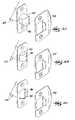
- FIG. 6Ais a partial side elevational view of the backplate assembly with the carrier component removed and the remote locking solenoid removed, showing the catch mechanism components;
- FIG. 6Bis a partial side elevational view of the backplate assembly with the carrier component removed and the remote locking solenoid removed, revealing the catch mechanism in a disengaged catch position;
- FIG. 7Ais an partially exploded perspective view of the deadbolt latch assembly and strike plate showing the deadbolt in an extended position
- FIG. 7Bis an partially exploded perspective view of the deadbolt latch assembly and strike plate showing the deadbolt in a partially extended position
- FIG. 7Cis an partially exploded perspective view of the deadbolt latch assembly and strike plate showing the deadbolt in a retracted position
- FIG. 8Ais a partial side elevational view of the backplate assembly with the carrier component removed, revealing the remote locking mechanism components;
- FIG. 8Bis a partial side elevational view of the backplate assembly with the carrier component removed, revealing the remote locking mechanism in a disengaged catch position;
- FIG. 9is a top plan view of the remote locking transmitter used with the remote locking feature of the present invention.
- lock assembly 10comprises a first or lower interconnected lock assembly 18 comprising outside housing assembly 12 , rose 14 , and outside knob/lever 16 , attached from the outside of a door (not shown) through a first or lower bore in the door, and through a back plate assembly 20 positioned on the inside of the door, to inside housing assembly 22 .
- Interconnect cam 24 , escutcheon assembly 28 , and inside knob/lever 26are attached to inside housing assembly 22 on the inside of the door.
- Interconnected lock assembly 10also comprises a second or upper interconnected lock assembly 40 comprising a deadbolt housing assembly 42 and a deadbolt latch assembly 44 .
- Deadbolt housing assembly 42is attached from the outside of the door through a second or upper bore and operably connected to deadbolt latch assembly 44 , and through back plate assembly 20 and secured thereto by deadbolt plate 46 and mounting screws 48 .
- Deadbolt housing assembly 42is operably connected to a deadbolt pinion 50 which engages a deadbolt rack 52 connected to back plate assembly 20 as discussed in detail below.
- the lower interconnected lock 18 and upper interconnected lock 40are standard configurations that are well-known in the art, and as such, the workings of these locks will not be described in detail, except as they relate to the present invention.
- Back plate assembly 20comprises a carrier component 54 vertically movable on, and slidably attached to a back plate 56 by a plurality of tangs 58 .
- Deadbolt rack 52is oriented vertically and fixedly attached to carrier component 54 such that it engages pinion 50 .
- Interconnected lock 10is adjustable in that upper lock assembly 40 can move up or down to properly fit the upper bore of the door.
- Deadbolt plate 46is movable within a slot 62 in back plate 56 to allow the proper positioning of upper lock assembly 40 .
- Upper lock assembly 40is then secured to deadbolt plate 46 by mounting screws 48 which secure upper lock assembly 40 in a fixed position.
- Deadbolt assembly 42is operably connected to deadbolt pinion 50 by a driver bar 60 which is co-rotatingly attached to deadbolt pinion 50 .
- Carrier component 54is shown in a 15 raised, or unlock position.
- a mating cam surface 64 of carrier component 54engages cam 24 .
- Cam 24is attached to knob/lever 26 in a co-rotating manner such that rotation of knob/lever 26 rotates cam 24 which engages mating cam surface 64 , causing carrier component 54 to move vertically, upwardly to a raised, or unlock position.
- the rack 52 attached to carrier component 54causes deadbolt pinion 50 to rotate as carrier component 54 moves either upward or downward.
- Deadbolt 90is shown in an extended position and a retracted position in FIGS. 7A and 7C, respectively.
- Deadbolt 90is distinguished from standard deadbolts in that deadbolt 90 includes a cam surface 96 at a distal end. While cam surface 96 is similar to cam surfaces used in standard spring latch assemblies, cam surface 96 only partially extends along the extended deadbolt 90 as best shown in FIG. 7 C.
- the doorcannot be closed when the deadbolt 90 is in an extended position.
- the deadbolt 90is partially extended in a manner that cam surface 96 is configured as shown in FIG. 7B, the door can be closed as cam surface 96 will engage strike plate 94 , forcing deadbolt 90 to retract.
- depression of deadbolt 90results in deadbolt latch assembly 44 rotating deadbolt pinion 50 in a standard manner, moving carrier component 54 to a raised position.
- escutcheon assembly 28comprises escutcheon 30 , thumbturn 32 , and thumbturn link component 34 .
- Thumbturn 32is coupled to thumbturn link component 34 in a co-rotating manner through an aperture in escutcheon 30 .
- Thumbturn link component 34comprises at least one pin 36 which engages an aperture 38 in rack 52 , linking thumbturn 32 to carrier component 54 .
- rack 52can be positioned on either side of carrier component 54 such that a pin 36 will engage an aperture 38 in rack 52 , allowing thumbturn 32 to be appropriately attached for right and left-hand opening doors. Movement of the carrier component 54 results in rotation of thumbturn 32 , and conversely, rotation of thumbturn 32 causes movement of carrier component 54 and extension and retraction of said deadbolt 90 .
- interconnected lock 10utilizes carrier component 54 which is biased in a downward, or locked position. Accordingly, a spring carriage 72 is attached to carrier component 54 .
- Spring carriage 72houses a spring 74 such that one end of spring 74 is attached to the assembled spring carriage 72 /carrier component 54 and the other end of spring 74 is fixedly attached to back plate 56 .
- Spring 74is of sufficient strength to cause carrier component 54 to move downward to locked position and cause extension of deadbolt 90 of deadbolt latch assembly 44 .
- Backplate assembly 20further comprises an electronic module 66 housing a power component 68 shown as a plurality of batteries to operate an automatic locking solenoid 70 and a signal receiver 75 .
- Electronic module 66may also be used to power a speaker 78 or status lights 91 .
- back plate assemblyincludes a catch mechanism 80 comprising a catch component 82 , a catch release 84 , and a spring trigger rod 86 as shown in FIGS. 6A and 6B.
- Catch component 82 and catch release 84are each pivotally attached to back plate 56 by a pin 88 .
- Catch release 84is biased toward catch component 82 by catch release spring 83 .
- Spring trigger rod 86is affixed to carrier component 54 and moves along a guide portion 92 in catch component 82 .
- Spring trigger rod 86is also biased toward spring 74 .
- interconnected lock 10The operation of interconnected lock 10 is best described in a dynamic manner starting with carrier component 54 positioned in a lowered, or locked position.
- Interconnected lock 10includes a keyless exit feature which enables automatic locking actuation. Movement of carrier component 54 from a locked position to an unlocked position can be accomplished by either rotating inside knob/lever 26 , rotating thumbtum 32 , or by turning a key to rotate the rotating driver bar 60 of deadbolt assembly 42 , typically with a key. As carrier component 54 moves upward, spring trigger rod 86 moves upward along guide portion 92 of catch component 82 from its initial position A, shown in FIG. 6 A. Movement of carrier component 54 and attached rack 52 causes rotation of pinion 50 and driver bar 60 , retracting deadbolt 90 of deadbolt latch assembly 44 .
- trigger spring rod 86When carrier component 54 moves downward, trigger spring rod 86 will move downward from position C, through position B, back to position A. Spring trigger rod 86 deviates from guide path 92 in the downward direction. Guide path 92 of catch component 82 is configured with a ramp portion between lowered portions generally corresponding to positions A and C. Between positions A and C, trigger spring rod 86 moves up a ramp portion to a drop-off 76 shown generally adjacent to position B. In the downward direction, spring trigger rod 86 is forced by the wall of drop-off 76 to move off of catch component 82 to a position below a portion of catch release 84 . In normal operation of the lock 10 , spring trigger rod 86 will continue downward from position B and return to position A. Accordingly, standard operation of the lock does not affect the catch mechanism.
- thumbturn 32In order to actuate the keyless exit feature, when deadbolt 90 of deadbolt latch assembly 44 is retracted, thumbturn 32 is rotated to an intermediate position. Rotation of thumbturn 32 causes thumbturn link component 34 to rotate. At least one pin 36 of thumbturn link component 34 engages rack 52 , such that rotation of thumbturn 32 causes carrier component 54 to move partially downward, partially extending deadbolt 90 of deadbolt latch assembly 44 .
- spring trigger rod 86moves from position C to a position adjacent catch release 84 , shown as position B.
- the deadbolt 90is in a partially extended position such as that shown in FIG. 7 B.
- cam surface 96 of deadbolt 90is driven back by a strike plate 94 of the door jamb (not shown) such as when the door is closed, linear movement of deadbolt 90 within deadbolt latch assembly 44 is converted to rotation of deadbolt pinion 50 in a standard manner.
- Rotation of deadbolt pinion 50causes carrier component 54 to move upward, moving spring trigger rod 86 to position D, forcing catch release 84 to rotate and free catch 82 .
- This actionallows spring carriage 74 /carrier component 54 to move downward under the force of spring 72 .
- the deadbolt 90 of deadbolt latch assembly 44is fully extended via the interaction of the deadbolt pinion 50 and rack 52 .
- interconnected lock 10When the keyless exit function is not in use, interconnected lock 10 will operate as a normal, or standard, interconnected lock.
- the remote locking feature of the present inventionutilizes solenoid 70 operably connected to catch release 84 as shown in FIG. 8A.
- a remote signal device 98is utilized with the remote locking mechanism, shown in FIG. 9 as a standard keychain transmitter of the type used to unlock cars, garages, etc.,
- solenoid 70retracts catch release 84 , allowing catch component 82 to rotate away from spring carriage component 72 , as shown in FIG. 8 B.
- Carrier component 54is then permitted to move downward under the biasing force of spring 74 . As previously described, downward movement of carrier component 54 causes extension of deadbolt 90 of deadbolt latch assembly 44 , thus locking the door.
Landscapes
- Business, Economics & Management (AREA)
- Emergency Management (AREA)
- Engineering & Computer Science (AREA)
- Structural Engineering (AREA)
- Lock And Its Accessories (AREA)
Abstract
Description
Claims (11)
Priority Applications (2)
| Application Number | Priority Date | Filing Date | Title |
|---|---|---|---|
| CA 2331426CA2331426C (en) | 2000-01-19 | 2001-01-19 | Interconnected lock with remote locking mechanism |
| US09/765,862US6612141B2 (en) | 2000-01-19 | 2001-01-19 | Interconnected lock with remote locking mechanism |
Applications Claiming Priority (2)
| Application Number | Priority Date | Filing Date | Title |
|---|---|---|---|
| US17699600P | 2000-01-19 | 2000-01-19 | |
| US09/765,862US6612141B2 (en) | 2000-01-19 | 2001-01-19 | Interconnected lock with remote locking mechanism |
Publications (2)
| Publication Number | Publication Date |
|---|---|
| US20010025517A1 US20010025517A1 (en) | 2001-10-04 |
| US6612141B2true US6612141B2 (en) | 2003-09-02 |
Family
ID=26872828
Family Applications (1)
| Application Number | Title | Priority Date | Filing Date |
|---|---|---|---|
| US09/765,862Expired - LifetimeUS6612141B2 (en) | 2000-01-19 | 2001-01-19 | Interconnected lock with remote locking mechanism |
Country Status (2)
| Country | Link |
|---|---|
| US (1) | US6612141B2 (en) |
| CA (1) | CA2331426C (en) |
Cited By (25)
| Publication number | Priority date | Publication date | Assignee | Title |
|---|---|---|---|---|
| US20060144102A1 (en)* | 2002-11-29 | 2006-07-06 | Inovec Pty Ltd. | Dual lock apparatus |
| US20060248931A1 (en)* | 2005-04-27 | 2006-11-09 | Robert Boulard | Keyless entry system |
| US20070056338A1 (en)* | 2005-09-13 | 2007-03-15 | Eaton Corporation | Lock device and system employing a door lock device |
| US20070137267A1 (en)* | 2005-12-16 | 2007-06-21 | Newfrey Llc | Lock set to deadbolt interlock |
| US20080041445A1 (en)* | 2006-04-18 | 2008-02-21 | Miller John J Jr | Energy capture system |
| US20080084299A1 (en)* | 2005-11-15 | 2008-04-10 | Joseph John Fisher | System and method for determining a state of a door |
| US20090038353A1 (en)* | 2000-05-18 | 2009-02-12 | Inovec Pty Ltd | Dual lock apparatus |
| US7698917B2 (en) | 2006-03-06 | 2010-04-20 | Handytrac Systems, Llc | Electronic deadbolt lock with a leverage handle |
| US20110265527A1 (en)* | 2009-01-05 | 2011-11-03 | Simo Saari | Wirelessly controlled electric lock |
| CN101755100B (en)* | 2007-08-15 | 2013-01-23 | 多玛两合有限公司 | Door lock |
| US8434335B2 (en) | 2010-06-28 | 2013-05-07 | Schlage Lock Company | Combination door latch and deadbolt assembly |
| WO2016188457A1 (en)* | 2015-05-28 | 2016-12-01 | 浙江凯迪仕实业有限公司 | Multidirectional transmission device based on american-standard lock body |
| WO2017209656A1 (en)* | 2016-05-31 | 2017-12-07 | Денис Аркадьевич ГОРОХОВ | Door handle |
| US10400477B2 (en) | 2015-11-03 | 2019-09-03 | Townsteel, Inc. | Electronic deadbolt |
| USD885865S1 (en)* | 2019-01-16 | 2020-06-02 | SimpliSafe, Inc. | Door lock |
| USD887249S1 (en)* | 2019-01-16 | 2020-06-16 | SimpliSafe, Inc. | Door lock |
| USD887248S1 (en)* | 2019-01-16 | 2020-06-16 | SimpliSafe, Inc. | Door lock |
| USD888536S1 (en)* | 2019-01-04 | 2020-06-30 | Schlage Lock Company Llc | Compact electronic lock |
| USD888537S1 (en)* | 2019-01-16 | 2020-06-30 | SimpliSafe, Inc. | Door lock |
| USD896614S1 (en)* | 2019-02-20 | 2020-09-22 | Brainchild Electronic Co., Ltd. | Door lock |
| US10890020B2 (en) | 2016-12-29 | 2021-01-12 | Townsteel, Inc. | Double latch lockset |
| US11124992B2 (en) | 2016-12-29 | 2021-09-21 | Townsteel, Inc. | Sliding actuator assembly for a latchset |
| US11639617B1 (en) | 2019-04-03 | 2023-05-02 | The Chamberlain Group Llc | Access control system and method |
| USD1009593S1 (en)* | 2019-01-07 | 2024-01-02 | Spectrum Brands, Inc. | Electronic door lock |
| US12320149B2 (en) | 2020-11-09 | 2025-06-03 | Townsteel Inc. | Lockset with sliding spindle |
Families Citing this family (6)
| Publication number | Priority date | Publication date | Assignee | Title |
|---|---|---|---|---|
| IL153763A0 (en)* | 2002-12-31 | 2003-07-06 | Rav Bariach Security Products | Safety catch for mortise lock |
| GB0307108D0 (en)* | 2003-03-27 | 2003-04-30 | Fullex Locks Ltd | Lock apparatus |
| USD559077S1 (en)* | 2006-06-29 | 2008-01-08 | The Boeing Company | Decompression rotary latch |
| CN105378197B (en)* | 2013-03-05 | 2018-09-07 | Utc 消防及保安公司 | The lock core of knob is popped up with concave type |
| US10657795B1 (en) | 2019-02-01 | 2020-05-19 | SimpliSafe, Inc. | Alarm system with first responder code for building access |
| US11933092B2 (en) | 2019-08-13 | 2024-03-19 | SimpliSafe, Inc. | Mounting assembly for door lock |
Citations (73)
| Publication number | Priority date | Publication date | Assignee | Title |
|---|---|---|---|---|
| US897686A (en) | 1908-03-18 | 1908-09-01 | Russell & Erwin Mfg Co | Lock construction. |
| US2862750A (en) | 1956-03-05 | 1958-12-02 | Robert M Minke | Door latch operating mechanism |
| DE2026582A1 (en) | 1970-05-30 | 1971-12-16 | Jul Niederdrenk Fa | Right and left usable furniture closed |
| US3744285A (en) | 1971-04-05 | 1973-07-10 | Security Tech Inc | Ignition & hood lock assembly for automotive vehicle |
| US3751088A (en) | 1971-05-24 | 1973-08-07 | Schlage Lock Co | Electromagnetic lock |
| US3791180A (en) | 1972-04-24 | 1974-02-12 | Emhart Corp | Combined latch bolt and dead bolt mechanism including single action double bolt release |
| US3910613A (en) | 1973-12-18 | 1975-10-07 | Tool Research & Engineering Co | Panic proof lock set |
| US3999789A (en) | 1976-01-15 | 1976-12-28 | Kysor Industrial Corporation | Lock |
| US4021065A (en) | 1975-07-08 | 1977-05-03 | Geringer Arthur V | Electric lock |
| US4073527A (en) | 1977-01-12 | 1978-02-14 | Schlage Lock Company | Electrically controlled door lock |
| US4129019A (en) | 1977-05-16 | 1978-12-12 | Schlage Lock Company | Cartridge for a lockset |
| US4262504A (en) | 1976-12-03 | 1981-04-21 | Alps Electric Co., Ltd. | Locking device |
| US4276760A (en) | 1979-10-22 | 1981-07-07 | Nolin Roger J | Two-bolt lockset with simultaneous locking and unlocking of its bolts |
| US4364249A (en) | 1979-03-24 | 1982-12-21 | Kiekert Gmbh & Co. Kommanditgesellschaft | Central door-lock system for motor vehicles |
| US4509347A (en) | 1982-06-30 | 1985-04-09 | Southern Steel Company | Door locking system |
| US4800741A (en) | 1983-02-07 | 1989-01-31 | Sidney Kerschenbaum | Electrically and manually operable door lock with convenient backset selection |
| US4838053A (en) | 1988-03-21 | 1989-06-13 | Richard Shen | Heavy-duty panic proof lock unit |
| US4840050A (en) | 1986-04-14 | 1989-06-20 | Motohiro Gotanda | Lock device with trigger bolt |
| US4843851A (en)* | 1987-09-23 | 1989-07-04 | Emhart Industries Inc. | Locking mechanism for multifunctional electronic lock |
| US4946207A (en) | 1987-10-03 | 1990-08-07 | Newman Tonks Security Limited | Electrically controlled locks |
| US4979767A (en) | 1990-01-08 | 1990-12-25 | Taiwan Fu Hsing Industry Co., Ltd. | Opening device for a double lock |
| US4987968A (en) | 1988-08-19 | 1991-01-29 | Lectron Products, Inc. | In-line solenoid transmission interlock device |
| EP0431717A2 (en) | 1989-12-08 | 1991-06-12 | IKON AKTIENGESELLSCHAFT Präzisionstechnik | Protective door fitting |
| US5067755A (en) | 1989-06-30 | 1991-11-26 | James C Thomas | Locking mechanism for a safe door |
| US5083448A (en)* | 1988-11-25 | 1992-01-28 | Oy Abloy Security Ltd. | Electromechanical door lock |
| US5100184A (en) | 1991-02-20 | 1992-03-31 | Thomas Schmitt | Deadlatch assembly |
| US5148691A (en) | 1989-06-29 | 1992-09-22 | Assa Ab | Electrically and mechanically activatable lock mechanism |
| US5199288A (en) | 1990-10-24 | 1993-04-06 | Abloy Security Ltd. Oy | Electromechanical door lock |
| US5228730A (en) | 1992-09-02 | 1993-07-20 | Security People, Inc. | Apparatus for converting mechanical locks to operate electrically using momentary power |
| US5255547A (en) | 1992-08-19 | 1993-10-26 | General Motors Corporation | Ignition lock with dual unlocking modes |
| US5325687A (en) | 1993-04-15 | 1994-07-05 | Lin Jui Chang | Control mechanism for a door lock |
| US5339662A (en) | 1991-10-11 | 1994-08-23 | Ilco Unican, Inc. | Door locking system |
| US5421178A (en) | 1993-01-19 | 1995-06-06 | Best Lock Corporation | Motorized lock actuator for cylindrical lockset |
| US5457975A (en) | 1994-07-11 | 1995-10-17 | Securitech Group Inc. | Removable locking cylinder |
| US5475996A (en) | 1994-08-29 | 1995-12-19 | Chen; Tsun-Hsing | Electromagnetic door lock |
| US5484179A (en) | 1993-12-27 | 1996-01-16 | Von Duprin, Inc. | Failsafe electric locking lever trim |
| US5492382A (en) | 1994-05-27 | 1996-02-20 | Security & Control Equipment, Inc. | Electro-mechanical locks for security accesses |
| US5496082A (en) | 1994-12-20 | 1996-03-05 | Emhart Inc. | Interconnected lock |
| US5513510A (en) | 1994-12-15 | 1996-05-07 | Emhart Inc. | Handleset with thumb piece and rack |
| US5513505A (en) | 1993-08-26 | 1996-05-07 | Master Lock Company | Adjustable interconnected lock assembly |
| US5531086A (en) | 1994-08-15 | 1996-07-02 | Bryant; Randy K. | Keyless entry deadbolt lock |
| US5537848A (en) | 1994-06-27 | 1996-07-23 | General Motors Corporation | Deadbolt locking system |
| US5544507A (en)* | 1994-02-15 | 1996-08-13 | Taiwan Fu Hsing Industrial Co., Ltd. | Door lock assembly |
| US5611227A (en) | 1996-06-27 | 1997-03-18 | Emhart Inc. | Handleset with thumb piece and rack |
| US5636881A (en) | 1994-10-21 | 1997-06-10 | Star Lock Systems, Inc. | Automatic latching system with automated unlatching feature |
| US5636880A (en) | 1995-10-11 | 1997-06-10 | Milocon Corporation | Electronic lock |
| US5640863A (en) | 1995-09-06 | 1997-06-24 | Harrow Products, Inc. | Clutch mechanism for door lock system |
| US5655393A (en) | 1995-03-07 | 1997-08-12 | Tong-Lung Metal Industry Co., Ltd. | Door lock set with simultaneously retractable deadbolt and latch |
| US5657653A (en) | 1995-08-10 | 1997-08-19 | Schlage Lock Company | Dual lock with simultaneous retraction of latch and deadbolt by inside lever and uncoulpler between driving spindle and the lever |
| US5712626A (en) | 1991-09-19 | 1998-01-27 | Master Lock Company | Remotely-operated self-contained electronic lock security system assembly |
| US5713612A (en) | 1994-09-19 | 1998-02-03 | Master Lock Company | Adjustable interconnected lock assembly with automatic deadbolt |
| US5715713A (en) | 1996-01-11 | 1998-02-10 | General Motors Corporation | Door latch locking actuator assembly |
| GB2316122A (en) | 1996-08-09 | 1998-02-18 | Emhart Inc | Adjustable interconnected lock |
| US5787741A (en) | 1997-08-28 | 1998-08-04 | Shen; Mu-Lin | Cartridge assembly of a panic proof lock |
| US5791177A (en) | 1991-10-21 | 1998-08-11 | Bianco; James S. | Compact electronic lock |
| US5839304A (en) | 1996-01-16 | 1998-11-24 | Wills; William H. | Locking device for a parking brake |
| US5845524A (en) | 1996-05-21 | 1998-12-08 | Koehler; Joseph E. | Lock assembly |
| US5850733A (en)* | 1996-10-16 | 1998-12-22 | Capstone Turbine Corporation | Gaseous fuel compression and control system and method |
| US5852944A (en) | 1997-04-18 | 1998-12-29 | Stephen C. Cohen | Remotely controlled door lock |
| US5857365A (en) | 1997-05-02 | 1999-01-12 | Emhart Inc. | Electronically operated lock |
| US5862693A (en) | 1997-05-02 | 1999-01-26 | Fort Lock Corporation | Electronically controlled security lock |
| US5876073A (en) | 1997-05-05 | 1999-03-02 | Geringer; Arthur | Electrically operable door locking apparatus and method for operating the same |
| US5933086A (en) | 1991-09-19 | 1999-08-03 | Schlage Lock Company | Remotely-operated self-contained electronic lock security system assembly |
| US5941578A (en) | 1997-08-07 | 1999-08-24 | Shamblin; Rosco | Impact resistant safety door latch mechanism |
| US5943888A (en) | 1997-12-15 | 1999-08-31 | Lawson; Edward | Keyless entry mechanism |
| US5960656A (en) | 1998-09-02 | 1999-10-05 | Shyang Feng Electric & Machinery Co., Ltd. | Electronic lock |
| US5987941A (en) | 1997-05-01 | 1999-11-23 | Zocco; Chris J. | Weapons security apparatus |
| US6035676A (en)* | 1997-06-02 | 2000-03-14 | Hudspeth; Chad W. | System for remote operation of a deadbolt lock |
| US6112563A (en)* | 1998-10-02 | 2000-09-05 | Ramos; Israel | Remote control locking device |
| US6128933A (en) | 1998-08-07 | 2000-10-10 | Emhart Inc. | Adjustable interconnected lock |
| US6137409A (en)* | 1998-08-28 | 2000-10-24 | Stephens; Bruce Randall | Computer anti-theft system |
| US6216502B1 (en)* | 2000-04-04 | 2001-04-17 | Thomas Cannella | Keyless locking system |
| US6334636B1 (en)* | 2000-08-09 | 2002-01-01 | Taiwan Fu Hsing Industrial Co., Ltd. | Remotely controllable lock |
- 2001
- 2001-01-19CACA 2331426patent/CA2331426C/ennot_activeExpired - Lifetime
- 2001-01-19USUS09/765,862patent/US6612141B2/ennot_activeExpired - Lifetime
Patent Citations (74)
| Publication number | Priority date | Publication date | Assignee | Title |
|---|---|---|---|---|
| US897686A (en) | 1908-03-18 | 1908-09-01 | Russell & Erwin Mfg Co | Lock construction. |
| US2862750A (en) | 1956-03-05 | 1958-12-02 | Robert M Minke | Door latch operating mechanism |
| DE2026582A1 (en) | 1970-05-30 | 1971-12-16 | Jul Niederdrenk Fa | Right and left usable furniture closed |
| US3744285A (en) | 1971-04-05 | 1973-07-10 | Security Tech Inc | Ignition & hood lock assembly for automotive vehicle |
| US3751088A (en) | 1971-05-24 | 1973-08-07 | Schlage Lock Co | Electromagnetic lock |
| US3791180A (en) | 1972-04-24 | 1974-02-12 | Emhart Corp | Combined latch bolt and dead bolt mechanism including single action double bolt release |
| US3910613A (en) | 1973-12-18 | 1975-10-07 | Tool Research & Engineering Co | Panic proof lock set |
| US4021065A (en) | 1975-07-08 | 1977-05-03 | Geringer Arthur V | Electric lock |
| US3999789A (en) | 1976-01-15 | 1976-12-28 | Kysor Industrial Corporation | Lock |
| US4262504A (en) | 1976-12-03 | 1981-04-21 | Alps Electric Co., Ltd. | Locking device |
| US4073527A (en) | 1977-01-12 | 1978-02-14 | Schlage Lock Company | Electrically controlled door lock |
| US4129019A (en) | 1977-05-16 | 1978-12-12 | Schlage Lock Company | Cartridge for a lockset |
| US4364249A (en) | 1979-03-24 | 1982-12-21 | Kiekert Gmbh & Co. Kommanditgesellschaft | Central door-lock system for motor vehicles |
| US4276760A (en) | 1979-10-22 | 1981-07-07 | Nolin Roger J | Two-bolt lockset with simultaneous locking and unlocking of its bolts |
| US4509347A (en) | 1982-06-30 | 1985-04-09 | Southern Steel Company | Door locking system |
| US4800741A (en) | 1983-02-07 | 1989-01-31 | Sidney Kerschenbaum | Electrically and manually operable door lock with convenient backset selection |
| US4840050A (en) | 1986-04-14 | 1989-06-20 | Motohiro Gotanda | Lock device with trigger bolt |
| US4843851A (en)* | 1987-09-23 | 1989-07-04 | Emhart Industries Inc. | Locking mechanism for multifunctional electronic lock |
| US4946207A (en) | 1987-10-03 | 1990-08-07 | Newman Tonks Security Limited | Electrically controlled locks |
| US4838053A (en) | 1988-03-21 | 1989-06-13 | Richard Shen | Heavy-duty panic proof lock unit |
| US4987968A (en) | 1988-08-19 | 1991-01-29 | Lectron Products, Inc. | In-line solenoid transmission interlock device |
| US5083448A (en)* | 1988-11-25 | 1992-01-28 | Oy Abloy Security Ltd. | Electromechanical door lock |
| US5148691A (en) | 1989-06-29 | 1992-09-22 | Assa Ab | Electrically and mechanically activatable lock mechanism |
| US5067755A (en) | 1989-06-30 | 1991-11-26 | James C Thomas | Locking mechanism for a safe door |
| EP0431717A2 (en) | 1989-12-08 | 1991-06-12 | IKON AKTIENGESELLSCHAFT Präzisionstechnik | Protective door fitting |
| US4979767A (en) | 1990-01-08 | 1990-12-25 | Taiwan Fu Hsing Industry Co., Ltd. | Opening device for a double lock |
| US5199288A (en) | 1990-10-24 | 1993-04-06 | Abloy Security Ltd. Oy | Electromechanical door lock |
| US5100184A (en) | 1991-02-20 | 1992-03-31 | Thomas Schmitt | Deadlatch assembly |
| US5933086A (en) | 1991-09-19 | 1999-08-03 | Schlage Lock Company | Remotely-operated self-contained electronic lock security system assembly |
| US5712626A (en) | 1991-09-19 | 1998-01-27 | Master Lock Company | Remotely-operated self-contained electronic lock security system assembly |
| US5339662A (en) | 1991-10-11 | 1994-08-23 | Ilco Unican, Inc. | Door locking system |
| US5791177A (en) | 1991-10-21 | 1998-08-11 | Bianco; James S. | Compact electronic lock |
| US5255547A (en) | 1992-08-19 | 1993-10-26 | General Motors Corporation | Ignition lock with dual unlocking modes |
| US5228730A (en) | 1992-09-02 | 1993-07-20 | Security People, Inc. | Apparatus for converting mechanical locks to operate electrically using momentary power |
| US5421178A (en) | 1993-01-19 | 1995-06-06 | Best Lock Corporation | Motorized lock actuator for cylindrical lockset |
| US5325687A (en) | 1993-04-15 | 1994-07-05 | Lin Jui Chang | Control mechanism for a door lock |
| US5513505A (en) | 1993-08-26 | 1996-05-07 | Master Lock Company | Adjustable interconnected lock assembly |
| US5484179A (en) | 1993-12-27 | 1996-01-16 | Von Duprin, Inc. | Failsafe electric locking lever trim |
| US5544507A (en)* | 1994-02-15 | 1996-08-13 | Taiwan Fu Hsing Industrial Co., Ltd. | Door lock assembly |
| US5492382A (en) | 1994-05-27 | 1996-02-20 | Security & Control Equipment, Inc. | Electro-mechanical locks for security accesses |
| US5537848A (en) | 1994-06-27 | 1996-07-23 | General Motors Corporation | Deadbolt locking system |
| US5457975A (en) | 1994-07-11 | 1995-10-17 | Securitech Group Inc. | Removable locking cylinder |
| US5531086A (en) | 1994-08-15 | 1996-07-02 | Bryant; Randy K. | Keyless entry deadbolt lock |
| US5475996A (en) | 1994-08-29 | 1995-12-19 | Chen; Tsun-Hsing | Electromagnetic door lock |
| US5713612A (en) | 1994-09-19 | 1998-02-03 | Master Lock Company | Adjustable interconnected lock assembly with automatic deadbolt |
| US5636881A (en) | 1994-10-21 | 1997-06-10 | Star Lock Systems, Inc. | Automatic latching system with automated unlatching feature |
| US5513510A (en) | 1994-12-15 | 1996-05-07 | Emhart Inc. | Handleset with thumb piece and rack |
| US5496082A (en) | 1994-12-20 | 1996-03-05 | Emhart Inc. | Interconnected lock |
| US5655393A (en) | 1995-03-07 | 1997-08-12 | Tong-Lung Metal Industry Co., Ltd. | Door lock set with simultaneously retractable deadbolt and latch |
| US5657653A (en) | 1995-08-10 | 1997-08-19 | Schlage Lock Company | Dual lock with simultaneous retraction of latch and deadbolt by inside lever and uncoulpler between driving spindle and the lever |
| US5640863A (en) | 1995-09-06 | 1997-06-24 | Harrow Products, Inc. | Clutch mechanism for door lock system |
| US5636880A (en) | 1995-10-11 | 1997-06-10 | Milocon Corporation | Electronic lock |
| US5715713A (en) | 1996-01-11 | 1998-02-10 | General Motors Corporation | Door latch locking actuator assembly |
| US5839304A (en) | 1996-01-16 | 1998-11-24 | Wills; William H. | Locking device for a parking brake |
| US5845524A (en) | 1996-05-21 | 1998-12-08 | Koehler; Joseph E. | Lock assembly |
| US5611227A (en) | 1996-06-27 | 1997-03-18 | Emhart Inc. | Handleset with thumb piece and rack |
| US5810402A (en) | 1996-08-09 | 1998-09-22 | Emhart Inc. | Adjustable interconnected lock |
| GB2316122A (en) | 1996-08-09 | 1998-02-18 | Emhart Inc | Adjustable interconnected lock |
| US5850733A (en)* | 1996-10-16 | 1998-12-22 | Capstone Turbine Corporation | Gaseous fuel compression and control system and method |
| US5852944A (en) | 1997-04-18 | 1998-12-29 | Stephen C. Cohen | Remotely controlled door lock |
| US5987941A (en) | 1997-05-01 | 1999-11-23 | Zocco; Chris J. | Weapons security apparatus |
| US5857365A (en) | 1997-05-02 | 1999-01-12 | Emhart Inc. | Electronically operated lock |
| US5862693A (en) | 1997-05-02 | 1999-01-26 | Fort Lock Corporation | Electronically controlled security lock |
| US5876073A (en) | 1997-05-05 | 1999-03-02 | Geringer; Arthur | Electrically operable door locking apparatus and method for operating the same |
| US6035676A (en)* | 1997-06-02 | 2000-03-14 | Hudspeth; Chad W. | System for remote operation of a deadbolt lock |
| US5941578A (en) | 1997-08-07 | 1999-08-24 | Shamblin; Rosco | Impact resistant safety door latch mechanism |
| US5787741A (en) | 1997-08-28 | 1998-08-04 | Shen; Mu-Lin | Cartridge assembly of a panic proof lock |
| US5943888A (en) | 1997-12-15 | 1999-08-31 | Lawson; Edward | Keyless entry mechanism |
| US6128933A (en) | 1998-08-07 | 2000-10-10 | Emhart Inc. | Adjustable interconnected lock |
| US6137409A (en)* | 1998-08-28 | 2000-10-24 | Stephens; Bruce Randall | Computer anti-theft system |
| US5960656A (en) | 1998-09-02 | 1999-10-05 | Shyang Feng Electric & Machinery Co., Ltd. | Electronic lock |
| US6112563A (en)* | 1998-10-02 | 2000-09-05 | Ramos; Israel | Remote control locking device |
| US6216502B1 (en)* | 2000-04-04 | 2001-04-17 | Thomas Cannella | Keyless locking system |
| US6334636B1 (en)* | 2000-08-09 | 2002-01-01 | Taiwan Fu Hsing Industrial Co., Ltd. | Remotely controllable lock |
Cited By (31)
| Publication number | Priority date | Publication date | Assignee | Title |
|---|---|---|---|---|
| US8522582B2 (en)* | 2000-05-18 | 2013-09-03 | Kym John Keightley | Dual lock apparatus |
| US20090038353A1 (en)* | 2000-05-18 | 2009-02-12 | Inovec Pty Ltd | Dual lock apparatus |
| US20060144102A1 (en)* | 2002-11-29 | 2006-07-06 | Inovec Pty Ltd. | Dual lock apparatus |
| US20060248931A1 (en)* | 2005-04-27 | 2006-11-09 | Robert Boulard | Keyless entry system |
| US7439850B2 (en) | 2005-04-27 | 2008-10-21 | Superb Industries, Inc. | Keyless entry system |
| US20070056338A1 (en)* | 2005-09-13 | 2007-03-15 | Eaton Corporation | Lock device and system employing a door lock device |
| US7520152B2 (en) | 2005-09-13 | 2009-04-21 | Eaton Corporation | Lock device and system employing a door lock device |
| US20080084299A1 (en)* | 2005-11-15 | 2008-04-10 | Joseph John Fisher | System and method for determining a state of a door |
| US7388467B2 (en) | 2005-11-15 | 2008-06-17 | Ge Security, Inc. | System and method for determining a state of a door |
| US20070137267A1 (en)* | 2005-12-16 | 2007-06-21 | Newfrey Llc | Lock set to deadbolt interlock |
| US7698917B2 (en) | 2006-03-06 | 2010-04-20 | Handytrac Systems, Llc | Electronic deadbolt lock with a leverage handle |
| US8033147B2 (en) | 2006-03-06 | 2011-10-11 | Handytrac Systems, Llc | Electronic deadbolt lock with a leverage handle |
| US20080041445A1 (en)* | 2006-04-18 | 2008-02-21 | Miller John J Jr | Energy capture system |
| CN101755100B (en)* | 2007-08-15 | 2013-01-23 | 多玛两合有限公司 | Door lock |
| US20110265527A1 (en)* | 2009-01-05 | 2011-11-03 | Simo Saari | Wirelessly controlled electric lock |
| US8490444B2 (en)* | 2009-01-05 | 2013-07-23 | Megalock Oy | Wirelessly controlled electric lock |
| US8434335B2 (en) | 2010-06-28 | 2013-05-07 | Schlage Lock Company | Combination door latch and deadbolt assembly |
| WO2016188457A1 (en)* | 2015-05-28 | 2016-12-01 | 浙江凯迪仕实业有限公司 | Multidirectional transmission device based on american-standard lock body |
| US10400477B2 (en) | 2015-11-03 | 2019-09-03 | Townsteel, Inc. | Electronic deadbolt |
| WO2017209656A1 (en)* | 2016-05-31 | 2017-12-07 | Денис Аркадьевич ГОРОХОВ | Door handle |
| US11124992B2 (en) | 2016-12-29 | 2021-09-21 | Townsteel, Inc. | Sliding actuator assembly for a latchset |
| US10890020B2 (en) | 2016-12-29 | 2021-01-12 | Townsteel, Inc. | Double latch lockset |
| USD888536S1 (en)* | 2019-01-04 | 2020-06-30 | Schlage Lock Company Llc | Compact electronic lock |
| USD1009593S1 (en)* | 2019-01-07 | 2024-01-02 | Spectrum Brands, Inc. | Electronic door lock |
| USD887248S1 (en)* | 2019-01-16 | 2020-06-16 | SimpliSafe, Inc. | Door lock |
| USD888537S1 (en)* | 2019-01-16 | 2020-06-30 | SimpliSafe, Inc. | Door lock |
| USD887249S1 (en)* | 2019-01-16 | 2020-06-16 | SimpliSafe, Inc. | Door lock |
| USD885865S1 (en)* | 2019-01-16 | 2020-06-02 | SimpliSafe, Inc. | Door lock |
| USD896614S1 (en)* | 2019-02-20 | 2020-09-22 | Brainchild Electronic Co., Ltd. | Door lock |
| US11639617B1 (en) | 2019-04-03 | 2023-05-02 | The Chamberlain Group Llc | Access control system and method |
| US12320149B2 (en) | 2020-11-09 | 2025-06-03 | Townsteel Inc. | Lockset with sliding spindle |
Also Published As
| Publication number | Publication date |
|---|---|
| CA2331426C (en) | 2009-07-28 |
| US20010025517A1 (en) | 2001-10-04 |
| CA2331426A1 (en) | 2001-07-19 |
Similar Documents
| Publication | Publication Date | Title |
|---|---|---|
| US6612141B2 (en) | Interconnected lock with remote locking mechanism | |
| US6581426B2 (en) | Interconnected lock with remote unlocking mechanism | |
| US6584818B2 (en) | Interconnected lock with lock status sensor | |
| US6615629B2 (en) | Interconnected lock with door status sensor | |
| US7025394B1 (en) | Lock system for integrating into an entry door having a vertical expanse and providing simultaneous multi-point locking along the vertical expanse of the entry door | |
| US9771740B2 (en) | Latches for gates and doors | |
| US8690203B1 (en) | Mortise lock with lockable handles | |
| US6578888B1 (en) | Mortise lock with automatic deadbolt | |
| US7634928B2 (en) | Door locking system | |
| US4333324A (en) | Spring/dead bolt lock assembly | |
| CA2665938C (en) | A mortice lock | |
| US6354121B1 (en) | Mortise lockset with internal clutch | |
| CA1241358A (en) | Automatic deadbolt | |
| US6131966A (en) | Latch holdback mechanism for a mortise lock | |
| US20010028172A1 (en) | Interconnected lock with keyless exit | |
| US5878605A (en) | Lock, in particular mortise lock | |
| KR20010071324A (en) | Mortise lock | |
| CA2246211A1 (en) | Deadbolt combination locking system with automatic locking spring bolt | |
| US4290282A (en) | Single cylinder deadbolt lock mechanism | |
| US4709566A (en) | Single cylinder deadbolt lock mechanism | |
| US6007115A (en) | Door lock assembly | |
| US6196035B1 (en) | Door lock assembly having an automatically actuated latch mechanism | |
| US20020096888A1 (en) | Interconnected lock with thumbturn rack connection | |
| CA2024262A1 (en) | High security panic exit system | |
| JPS5849332Y2 (en) | Latch locking mechanism in door locking device |
Legal Events
| Date | Code | Title | Description |
|---|---|---|---|
| AS | Assignment | Owner name:SCHLAGE LOCK COMPANY, COLORADO Free format text:ASSIGNMENT OF ASSIGNORS INTEREST;ASSIGNORS:BATES, PETER K.;BUSSIERE, JOHN;DOERR, ALAN;REEL/FRAME:012518/0145 Effective date:20020111 | |
| STCF | Information on status: patent grant | Free format text:PATENTED CASE | |
| FPAY | Fee payment | Year of fee payment:4 | |
| FPAY | Fee payment | Year of fee payment:8 | |
| AS | Assignment | Owner name:SCHLAGE LOCK COMPANY LLC, INDIANA Free format text:NUNC PRO TUNC ASSIGNMENT;ASSIGNOR:SCHLAGE LOCK COMPANY;REEL/FRAME:031731/0273 Effective date:20131126 | |
| AS | Assignment | Owner name:JPMORGAN CHASE BANK, N.A., AS ADMINISTRATIVE AGENT Free format text:SECURITY AGREEMENT;ASSIGNOR:SCHLAGE LOCK COMPANY LLC;REEL/FRAME:031831/0091 Effective date:20131126 | |
| AS | Assignment | Owner name:JPMORGAN CHASE BANK, N.A., AS ADMINISTRATIVE AGENT Free format text:SECURITY AGREEMENT;ASSIGNOR:SCHLAGE LOCK COMPANY LLC;REEL/FRAME:034173/0001 Effective date:20141015 | |
| FPAY | Fee payment | Year of fee payment:12 |