US6611691B1 - Antenna adapted to operate in a plurality of frequency bands - Google Patents
Antenna adapted to operate in a plurality of frequency bandsDownload PDFInfo
- Publication number
- US6611691B1 US6611691B1US09/219,561US21956198AUS6611691B1US 6611691 B1US6611691 B1US 6611691B1US 21956198 AUS21956198 AUS 21956198AUS 6611691 B1US6611691 B1US 6611691B1
- Authority
- US
- United States
- Prior art keywords
- antenna
- contact
- whip
- coupled
- whip portion
- Prior art date
- Legal status (The legal status is an assumption and is not a legal conclusion. Google has not performed a legal analysis and makes no representation as to the accuracy of the status listed.)
- Expired - Lifetime
Links
- 230000004044responseEffects0.000claimsdescription4
- 238000004891communicationMethods0.000description33
- 230000008878couplingEffects0.000description17
- 238000010168coupling processMethods0.000description17
- 238000005859coupling reactionMethods0.000description17
- IRLPACMLTUPBCL-KQYNXXCUSA-N5'-adenylyl sulfateChemical compoundC1=NC=2C(N)=NC=NC=2N1[C@@H]1O[C@H](COP(O)(=O)OS(O)(=O)=O)[C@@H](O)[C@H]1OIRLPACMLTUPBCL-KQYNXXCUSA-N0.000description12
- 230000005404monopoleEffects0.000description11
- 230000005540biological transmissionEffects0.000description10
- 239000003989dielectric materialSubstances0.000description7
- 239000004020conductorSubstances0.000description6
- 230000009977dual effectEffects0.000description6
- 230000001413cellular effectEffects0.000description5
- 230000006870functionEffects0.000description5
- 125000003345AMP groupChemical group0.000description4
- 229920006227ethylene-grafted-maleic anhydridePolymers0.000description4
- 238000000034methodMethods0.000description4
- 239000003990capacitorSubstances0.000description3
- 238000010586diagramMethods0.000description3
- 239000002184metalSubstances0.000description3
- 230000036961partial effectEffects0.000description3
- 230000003068static effectEffects0.000description3
- 239000004743PolypropyleneSubstances0.000description2
- 230000008859changeEffects0.000description2
- 238000013461designMethods0.000description2
- 239000000463materialSubstances0.000description2
- 230000010287polarizationEffects0.000description2
- -1polypropylenePolymers0.000description2
- 229920001155polypropylenePolymers0.000description2
- 230000008569processEffects0.000description2
- 230000002829reductive effectEffects0.000description2
- 239000004809TeflonSubstances0.000description1
- 229920006362Teflon®Polymers0.000description1
- 230000008901benefitEffects0.000description1
- 230000003247decreasing effectEffects0.000description1
- 238000011161developmentMethods0.000description1
- 230000018109developmental processEffects0.000description1
- 230000000694effectsEffects0.000description1
- 239000000203mixtureSubstances0.000description1
- 238000012986modificationMethods0.000description1
- 230000004048modificationEffects0.000description1
- 239000004033plasticSubstances0.000description1
- 229920003023plasticPolymers0.000description1
- 238000012545processingMethods0.000description1
- 230000000717retained effectEffects0.000description1
- 229920003031santoprenePolymers0.000description1
- 239000007787solidSubstances0.000description1
- 238000001228spectrumMethods0.000description1
- 239000010902strawSubstances0.000description1
Images


Classifications
- H—ELECTRICITY
- H01—ELECTRIC ELEMENTS
- H01Q—ANTENNAS, i.e. RADIO AERIALS
- H01Q21/00—Antenna arrays or systems
- H01Q21/30—Combinations of separate antenna units operating in different wavebands and connected to a common feeder system
- H—ELECTRICITY
- H01—ELECTRIC ELEMENTS
- H01Q—ANTENNAS, i.e. RADIO AERIALS
- H01Q1/00—Details of, or arrangements associated with, antennas
- H01Q1/12—Supports; Mounting means
- H01Q1/22—Supports; Mounting means by structural association with other equipment or articles
- H01Q1/24—Supports; Mounting means by structural association with other equipment or articles with receiving set
- H01Q1/241—Supports; Mounting means by structural association with other equipment or articles with receiving set used in mobile communications, e.g. GSM
- H01Q1/242—Supports; Mounting means by structural association with other equipment or articles with receiving set used in mobile communications, e.g. GSM specially adapted for hand-held use
- H01Q1/243—Supports; Mounting means by structural association with other equipment or articles with receiving set used in mobile communications, e.g. GSM specially adapted for hand-held use with built-in antennas
- H01Q1/244—Supports; Mounting means by structural association with other equipment or articles with receiving set used in mobile communications, e.g. GSM specially adapted for hand-held use with built-in antennas extendable from a housing along a given path
- H—ELECTRICITY
- H01—ELECTRIC ELEMENTS
- H01Q—ANTENNAS, i.e. RADIO AERIALS
- H01Q1/00—Details of, or arrangements associated with, antennas
- H01Q1/36—Structural form of radiating elements, e.g. cone, spiral, umbrella; Particular materials used therewith
- H01Q1/362—Structural form of radiating elements, e.g. cone, spiral, umbrella; Particular materials used therewith for broadside radiating helical antennas
- H—ELECTRICITY
- H01—ELECTRIC ELEMENTS
- H01Q—ANTENNAS, i.e. RADIO AERIALS
- H01Q11/00—Electrically-long antennas having dimensions more than twice the shortest operating wavelength and consisting of conductive active radiating elements
- H01Q11/02—Non-resonant antennas, e.g. travelling-wave antenna
- H01Q11/08—Helical antennas
- H—ELECTRICITY
- H01—ELECTRIC ELEMENTS
- H01Q—ANTENNAS, i.e. RADIO AERIALS
- H01Q5/00—Arrangements for simultaneous operation of antennas on two or more different wavebands, e.g. dual-band or multi-band arrangements
- H01Q5/40—Imbricated or interleaved structures; Combined or electromagnetically coupled arrangements, e.g. comprising two or more non-connected fed radiating elements
- H—ELECTRICITY
- H01—ELECTRIC ELEMENTS
- H01Q—ANTENNAS, i.e. RADIO AERIALS
- H01Q9/00—Electrically-short antennas having dimensions not more than twice the operating wavelength and consisting of conductive active radiating elements
- H01Q9/04—Resonant antennas
- H01Q9/30—Resonant antennas with feed to end of elongated active element, e.g. unipole
- H01Q9/32—Vertical arrangement of element
- H01Q9/36—Vertical arrangement of element with top loading
Definitions
- This applicationis related to an antenna, and more particularly to an antenna adapted to operate in more than one frequency band.
- service in a given regioncould be provided on a GSM system in a 900 MHz frequency band and on a DCS system at an 1800 MHz frequency band, or even a third system, such as a PCS system in a 1900 frequency band.
- service in another regioncould include an AMPS system in an 800 MHz frequency band and a PCS system in a 1900 frequency band.
- a single network operatormay not provide service in both systems in a given region, a user of a wireless communication device may like the opportunity to roam in the event he is unable to obtain service on one of the systems. Accordingly, wireless communication devices, such as cellular radio telephones, must be able to communicate at both frequencies.
- a conventional mechanical switch or a pin diodecan be used to change the matching circuit between the antenna and the transceiver when in up and down positions.
- switchesadd additional power loss when transmitting and receiving. More importantly, a mechanical switch is easily broken and a pin diode switch can be easily broken down by static discharge. Accordingly, there is a need for an antenna which can operate on more than one frequency, including such an antenna being retractable and having a novel matching circuit for the up and down positions.
- FIG. 1is a block diagram of a wireless communication device, such as a cellular radio telephone, according to the present invention
- FIG. 2is a partial perspective view of an antenna coupled to the wireless communication device of FIG. 1;
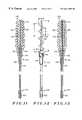
- FIG. 3is a plan view of an antenna according to the present invention.
- FIG. 4is a cross-sectional view of the antenna of FIG. 3 according to the present invention.
- FIG. 5is a cross-sectional view of an alternate embodiment of the antenna according to the present invention.
- FIG. 6is a plan view of antenna elements of FIG. 5 according to the present invention.
- FIG. 7is a cross-sectional view of an alternate embodiment of the antenna according to the present invention.
- FIG. 8is a plan view of antenna elements of FIG. 7 according to the present invention.
- FIG. 9is a chart showing the frequency response of the antenna of FIG. 5;
- FIG. 10is a circuit diagram showing the matching circuit of FIG. 1 according to the present invention.
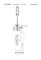
- FIG. 11is a cross-sectional view of an alternate embodiment of an antenna according to the present invention.
- FIG. 12is a plan view of antenna elements of FIG. 11 according to the present invention.
- FIG. 13is a cross-sectional view of an alternate embodiment of an antenna according to the present invention.
- FIG. 14is a plan view of antenna elements of FIG. 13 according to the present invention.
- FIG. 15is a cross-sectional view of an alternate embodiment of an antenna according to the present invention.
- FIG. 16is a cross-sectional view of an alternate embodiment of an antenna according to the present invention.
- FIG. 17is a cross-sectional view of an alternate embodiment of an antenna according to the present invention.
- FIG. 18is a cross-sectional view of an alternate embodiment of an antenna according to the present invention.
- FIG. 19is a cross-sectional view of an alternate embodiment of an antenna according to the present invention.
- FIG. 20is a plan view of a circuit board for a wireless communication device incorporating an antenna according to the present invention.
- FIG. 21is a plan view of a circuit board for a wireless communication device incorporating an antenna according to the present invention.
- FIG. 22is a plan view of a circuit board for a wireless communication device incorporating an antenna according to the present invention.
- FIG. 23is a plan view of a circuit board for a wireless communication device incorporating an antenna according to the present invention.
- FIG. 24is a plan view of a circuit board for a wireless communication device incorporating an antenna according to the present invention.
- FIG. 25is a cross sectional view of a circuit board for a wireless communication device incorporating an antenna according to the present invention.
- FIG. 26is a plan view of a circuit board for a wireless communication device incorporating an antenna according to the present invention.
- FIG. 27is a plan view of a circuit board for a wireless communication device incorporating an antenna according to the present invention.
- FIG. 28is a plan view of a circuit board for a wireless communication device incorporating an antenna according to the present invention.
- FIG. 29is a plan view of a circuit board for a wireless communication device incorporating an antenna according to the present invention.
- FIG. 30is a chart showing the frequency response of a retractable antenna of the present invention in the up position.
- FIG. 31is a chart showing the frequency response of a retractable antenna of the present invention in the down position.
- a dual-band antennais required to operate at both 800 MHz AMPS and 1900 MHz PCS in the U.S., or 900 MHz GSM and 1800 MHz DCS bands in Europe.
- a tri-band antennais required to operate at three of the bands.
- the antennapreferably comprises a fixed whip antenna and a helical coil antenna coupled to a single feedpoint.
- a single matching circuitis adapted to provide matching for both the whip antenna and the helical coil antenna, while also providing static protection.
- the antennacan also be reduced in size by attaching a disc to the end of the whip portion of the antenna, while decreasing the pitch of the helical coil.
- a dielectric materialpreferably surrounds the whip portion and provides support for the helical coil antenna.
- An attachment memberallowing the antenna to be coupled to the wireless communication device acts as a monopole which is top loaded with the fixed whip antenna and the helical coil antenna.
- a clipcan be used to provide a feed point for the antenna to further reduce the electrical lengths of the fixed whip antenna and a helical coil antenna.
- the antenna according to an alternate embodiment of the present inventionis preferably retractable and has a straight whip with a helical wire mounted on top.
- the antennais fed both in up and down positions by coupling RF energy through the metal bushing.
- the dual frequenciesare resonated by the length of the whip and a matching circuit coupled to the bottom of the whip.
- an extra matching circuitsuch as an LC network, is preferably connected at some other point along the whip, so that the whip is equivalent to an open circuit at the feed location.
- an LC networkis needed at the feed point for the matching. Since the retracted whip part is about 1 ⁇ 4 wavelength (at AMPS/GSM band) and ⁇ fraction (1/2 ) ⁇ wavelength (at DCS/PCS band), a novel technique to match the antenna is to electrically disconnect the whip at the feed point.
- the required load impedancepreferably either a series or a parallel LC circuit, should have a low impedance value at AMPS/GSM and high impedance value at DCS/PCS bands. Therefore, the antenna in down position is equivalent to a self-resonant dual band antenna.
- FIG. 1a block diagram of a wireless communication device such as a dual band cellular radiotelephone incorporating the present invention is shown.
- a frame generator ASIC 101such as a CMOS ASIC available from Motorola, Inc.
- a microprocessor 103such as a 68HC11 microprocessor also available from Motorola, Inc., combine to generate the necessary communication protocol for operating in a cellular system.
- Microprocessor 103uses memory 104 comprising RAM 105 , EEPROM 107 , and ROM 109 , preferably consolidated in one package 111 , to execute the steps necessary to generate the protocol and to perform other functions for the communication unit, such as writing to a display 113 , accepting information from a keypad 115 , controlling a frequency synthesizer 125 , or performing steps necessary to amplify a signal according to the method of the present invention.
- ASIC 101processes audio transformed by audio circuitry 119 from a microphone 117 and to a speaker 121 .
- a transceiverprocesses the radio frequency signals.
- a transmitters 123 and 124transmit through an antenna 129 using carrier frequencies produced by a frequency synthesizer 125 .
- Information received by the communication device's antenna 129enters receivers 127 and 128 through a matching network and transmit/receive switch 130 .
- a preferred matching network and transmit/receive switch 130will be shown in more detail in FIG. 10 .
- Receivers 127 and 128demodulate the symbols comprising the message frame using the carrier frequencies from frequency synthesizer 125 .
- the transmitters and receiversare collectively called a transceiver.
- the communication devicemay optionally include a message receiver and storage device 131 including digital signal processing means.
- the message receiver and storage devicecould be, for example, a digital answering machine or a paging receiver.
- FIG. 2a partial cross-sectional view shows an antenna according to the present invention coupled to a wireless communication device, such as that shown in FIG. 1 .
- Antenna 129comprises an outer housing or overmold 202 having a sleeve 204 .
- a monopole 205comprises a threaded portion 206 which extends to a coupling portion 208 .
- the length of the monopolegenerally effects vertical polarization, where a longer monopole generally provides greater vertical polarization.
- the monopolewill be described in more detail in reference to the remaining figures.
- the antennais coupled to a clip 210 having a contact element 212 at the end of a flexible arm 214 which is coupled to a base portion 216 .
- Base portion 216is preferably attached to a circuit board having circuitry of FIG. 1 or some other suitable circuit.
- Bracket 210further includes a second contact 218 coupled to flexible arm 220 which also extends to base portion 216 .
- Coupling portion 208is retained by flexible arms 214 and 220 which also provide an electrical contact.
- the dimensions of the flexible armsare preferably selected to optimize the efficiency of the antenna. That is, the length and width of the flexible arms are selected to provide the proper inductance or capacitance for the antenna, where a narrower arm provides greater inductance and wider arm provides greater capacitance.
- FIG. 2also shows a housing 230 of the wireless communication device of FIG. 1 .
- the housingincludes a receiving sleeve 232 , shown in partial cross-section, which retains a threaded nut 234 for receiving threaded portion 206 of the antenna.
- the feed point of the antennais preferably made at contact elements 212 and 218 near the base of coupling portion 205 , the feed point could be made at the threaded nut 234 according to the present invention.
- a dielectric core 404 within the overmold 202preferably comprises a dielectric material.
- the corecould be a dielectric material comprising santaprene and polypropylene.
- the dielectric corecould be composed of 75% santoprene and 25% polypropylene to create dielectric material having a dielectric constant of 2.0.
- dielectric sleeve 405covering a whip antenna 406 which is a substantially straight wire.
- dielectric sleeve 405could be a Teflon material.
- Dielectric core 402preferably has a dielectric constant ⁇ 1 dielectric sleeve preferably has a dielectric constant ⁇ 2 , where ⁇ 1 > ⁇ 2 .
- a helical coil antenna 408within a helical recess 407 formed in dielectric core 402 is a helical coil antenna 408 .
- the helical coil antennais formed on the outer edge of the dielectric core 402 , the helical antenna could also be completely surrounded by dielectric core 402 .
- Both the whip antenna and the helical coil antennaare electrically connected to the monopole 205 .
- a lower portion 410 of the whip antennais coupled to monopole 205 in a recess in a shoulder portion 411 of the monopole, while a lower portion 412 of helical coil antenna 408 is also coupled to a recess in the monopole.
- the helical coil antennais shown to substantially surround the whip antenna, the helical coil antenna could be adjacent to the whip antenna.
- FIG. 5an alternate embodiment of the cross-sectional view of the antenna is shown.
- dielectric sleeve 405is eliminated, leaving a dielectric core 502 surrounding whip antenna 406 .
- FIG. 6the perspective view of FIG. 6 shows whip antenna 406 and helical coil antenna 408 according to the present invention without any overmold or dielectric layers.
- the whip antennais selected to be a length l 1 of approximately 28.1 (+/ ⁇ 0.5) mm as measured from the shoulder of the monopole.
- the whip antennais selected to be a length l 1 of approximately 25.4 (+/ ⁇ 0.8) mm with a pitch dimension l 3 of approximately 7.15 mm and approximately 3.7 turns as also measured from the shoulder of the monopole.
- an alternate embodiment of the present inventionshows a shorter whip portion 702 having a disc 704 on the end of the antenna to shorten the overall length of the antenna.
- the pitch dimension of the helical coil antennacould also be reduced to enable the shortened length of the antenna.
- Other dimensions for the frequency bands mentioned or other frequency bandscould be used according to the present invention.
- FIG. 9a graph shows the return loss in 5 dB increments as a function of frequency according to the antenna of FIG. 5 of the present invention.
- the antennawill operate signals between 830-960 MHz band and 1710-2000 MHz band at ⁇ 10 dB return loss which covers the frequency bands of AMPS, GSM, DCS, PCS, and PHS.
- the resonating frequencycan be tuned to any frequency band desired.
- a matching network and transmit/receive switch 130shown in more detail.
- a matching network 1002comprising a capacitor 1004 and an inductor 1006 .
- capacitor 1004could be approximately 4.7 pf while inductor 1006 is approximately 8.2 nH, for example.
- Another benefit of the matching networkis that the inductor provides a DC path for providing static protection.
- any conventional transmit/receive switch 1008could be used according to the present invention.
- a dielectric core 1102 within the overmold 1101preferably comprises a dielectric material.
- the core and the overmoldcould comprise the same materials as those described in FIG. 4 .
- a whip portion 1106which is a substantially straight wire.
- a helical coil antenna 1108is coupled to a conductor member 1109 .
- Conductor member 1109enables a direct electrical contact of the helical portion and the top portion of whip portion 1106 to a bushing 1110 when the antenna is in the down position.
- the helical coil and the conductor membercould be, for example, a quarter wavelength in the GSM band.
- Bushing 1110which is movable with respect to overmold 1101 and whip portion 1106 , includes a shoulder portion 1112 , a threaded portion 1114 and a sleeve portion 1116 , and acts as a feedpoint for the helical coil and the top portion of the whip. Accordingly, when the antenna is in the down position, the helical coil and the top portion of the whip function in the same manner as the antenna of FIG. 5 .
- An insulating portion 1118covers the whip portion from conductor member 1109 to a contact 1120 at the distal end of the whip.
- Contact 1120preferably includes a recess 1122 extending around the contact to receive a contact on a circuit board to hold the antenna in the up position, as will be described in detail in reference to later figures.
- a plan view of antenna elements of FIG. 11 without dielectric materialsis shown in FIG. 12 . As described earlier with respect to FIG. 6, the dimensions of the helical coil and the properties of the dielectric material can be selected depending upon the desired frequency in the down position.
- FIG. 13a cross-sectional view of an alternate embodiment of an antenna according to the present invention is shown.
- the structureis substantially the same as the antenna of FIG. 11, except the antenna of FIG. 13 does not include conductor member 1109 . Rather, helical coil 1108 is connected directly to whip portion 1106 . Therefore, the helical coil and the upper portion of the whip are capacitively coupled to bushing 1110 .
- the direct connection of helical coil 1108 to whip portion 1106can be seen more clearly in FIG. 14
- FIG. 15a cross-sectional view of an alternate embodiment of an antenna according to the present invention is shown.
- the helical coilis no longer present, and the whip portion comprises the antenna element.
- the antennacould be capacitively coupled to bushing 1110 in the down position and directly coupled to bushing 1110 when recess 1122 makes contact to the bushing in the up position.
- FIGS. 16 and 17cross-sectional views of an alternate embodiment of an antenna according to the present invention are shown.
- FIGS. 16 and 17correspond to FIGS. 11 and 13, respectively, but include a metal contact, contacts 1602 and 1702 .
- contacts 1602 and 1702enable a direct coupling of whip portion 1106 to a matching circuit on a circuit board of a wireless communication device when the antenna is in the down position.
- FIG. 18a cross-sectional view of alternate embodiments of an antenna according to the present invention is shown.
- the whip portionis movable with respect to the helical portion.
- a cap 1802is connected to the top portion of whip portion 1106 , while overmold 1101 , dielectric core 1102 and helical coil 1108 remain fixed with respect to bushing 1110 .
- Whip portion 1106 and helical coil 1108are preferably directly coupled to contact member 1109 , which provides a direct contact to bushing 1110 .
- whip portion 1106could be capacitively coupled to bushing 1110 if conductor member 1109 is removed.
- the embodiment of FIG. 19further includes contact 1902 to enable a direct contact to a matching circuit, as will be described in more detail in reference to the remaining figures.
- the antennas described aboveintended for operation at dual band frequencies such as AMPS (824-894 MHz) and PCS (1850-1990 MHz) or GSM (890-960 MHz) and DCS (1710-1880 Mhz) and preferably have a single feed point. However, it can be used for any dual band or single band transceiver. The bandwidth can be narrow or wide. The same antenna element can be used in more than transceiver with or without a match change. Any of the antennas shown in FIGS. 11-19 could be employed in any of the various circuit board configurations having various matching circuit arrangements described in reference to FIGS. 20-29.
- FIG. 20a plan view of a circuit board 2002 for a wireless communication device incorporating an antenna according to the present invention is shown.
- the circuit boardincludes contacts 2004 , 2006 , and 2008 .
- Upper contact 2004preferably acts as a single feed point and is coupled to a matching circuit 2010 , which is coupled to communication circuitry 2012 .
- the antennais in the down position, most of the whip is retracted inside the phone housing. If the whip is selected as 3 ⁇ 4 wavelength in the DCS band, a 1 ⁇ 4 wavelength portion could be above the feedpoint and a 1 ⁇ 2 wavelength portion could be below the band.
- a 1 ⁇ 4 wavelength portion of the whipcould extend above the feedpoint.
- This part of the whipnot only mismatches the antenna but also radiates RF energy into the circuits on the PC board, which causes more phase errors and EM interference.
- a matching circuit 2010is used to electrically open this part of the whip at the bottom of the whip, so that this part of the whip is equivalently disconnected from the antenna in the down position. Because the length of the retracted part of antenna is about 1 ⁇ 4 wave length for AMPS/GSM and 1 ⁇ 2 wave length for DCS/PCS, we can matching network 2014 , preferably comprising an LC network.
- a second matching circuit 2014can be coupled to middle contact 2006 .
- Matching circuitsare well known in the art, and could include any LC network, such as the circuit shown in FIG. 10 .
- the value of the capacitor and the inductorare selected depending upon a number of factors, including the desired frequency, the dimensions, shape and compositions of the antenna elements, housings, etc.
- a second matching circuit 2014is preferably coupled to middle contact 2006 .
- the location of the middle contact 2006 along the whip portion 1106is selected by design choice including consideration of the factors in selecting the matching network.
- lower contact 2008which is coupled to ground, is directly coupled to recess 1122 .
- FIG. 21shows an antenna of the present invention in the up position.
- the whipIn the up position, the whip is fed by coupling energy into the antenna through the metal bushing. Two modes of antenna operation are excited by the choice of match, antenna length, and couple bushing.
- the antennais adjusted to have the first resonant mode on AMPS/GSM bands and the second resonant mode on DCS/PCS bands.
- the length of the whip portion 1106could be, for example, 3 ⁇ 4 of the wavelength for a frequency in the DCS band. Alternatively, it could be 3 ⁇ 4 wavelength in the PCS band, and 1 ⁇ 3 wavelength in the AMPS band.
- middle contact 2006can be coupled to ground in place of a matching circuit.
- FIG. 23a plan view of an alternate embodiment of a circuit board for a wireless communication device incorporating an antenna according to the present invention is shown. As is shown, middle contact 2006 is coupled to ground, while a matching circuit 2302 is coupled to lower contact 2008 .
- the retracted whipacts like a transmission line.
- a load impedance at the bottom of the whipwill be transformed transmission line formula
- ZZc ( ZL+jZc tan(l)/( Zc+jZL tan(l).
- a 1 ⁇ 4 wave length transmission line for AMPS/GSMwill transform a low impedance at lower contact 2008 to high impedance at upper contact 2004 .
- a 1 ⁇ 2 wave length transmission line for DCS/PCSstill transforms a high impedance at lower contact 2008 to a high impedance at upper contact 2004 .
- Matching circuit 2302in addition to the existing match for the transceiver at the feedpoint at the bushing, improves the antenna performance by providing a short at the lower band of frequencies and an open at the higher band of frequencies.
- the retracted position of the antennais close to a quarter wave length for the PCS/DCS frequency (which is resonant at PCS/DCS) and a short dipole at AMPs/GSM frequency (which is resonant at AMPs/GSM freq.)
- FIG. 24a plan view of a circuit board for a wireless communication device incorporating an antenna according to the present invention is shown. Since the retracted whip is not a perfect transmission line and the LC network cannot provide perfect short for AMPs/GSM and open for DCS/PCS, coupling to ground can be used to improve antenna performance as seen in FIG. 24 .
- the coupling pointis not a direct contact.
- a cylindrical ring 2402 coupled to matching circuit 2014enables capacitive coupling to the antenna.
- a cross section of the ringin shown in FIG. 25 .
- the location and amount of couplingare chosen to provide the desired antenna performance. This coupling to ground improves the open/short match of the antenna thereby improving the antenna performance when retracted.
- An alternative matchis shown in FIGS. 20 and 21, where the matching circuit is connected to the middle of the whip, but the bottom of the whip is grounded.
- FIGS. 26 and 27plan views of a circuit board for a wireless communication device incorporating the antenna of FIG. 18 is shown in the down position and up position respectively.
- FIGS. 28 and 29a plan view of a circuit board for a wireless communication device incorporating an antenna according to the present invention and a novel metalized tube or straw is shown.
- a tube 2802has a metalized portion 2804 extending a length “l”. The length can be adjusted to properly match the antenna as needed.
- the metalized tubepreferably replaces a matching circuit coupled to middle contact 2006 .
- the metalized tube and the whip of the antennaform a coaxial transmission line.
- the impedance of the transmission lineis characterized using transmission line theory and can be varied by adjusting the length and diameter of the metalized portion of the tube. In particular, the impedance characteristics of the enclosed transmission line is
- the impedance of the whip not covered by the tubeis covered by the equation set forth earlier. Properly choosing the length of the metalized portion of the tube will provide the right impedance for the antenna matching. Alternatively, a matching circuit could be used in conjunction with tube 2802 .
- FIGS. 30 and 31graphs show the return loss in 5 dB increments as a function of frequency according to the antennas of FIGS. 11-19 of the present invention in the down and up positions respectively.
- the resonating frequencycan be tuned to any frequency band desired.
- FIGS. 20-29show contacts 2004 , 2006 , and 2008 as being either direct coupling or capacitive coupling, direct coupling contacts and capacitive coupling contacts could be freely interchanged.
- any antenna of FIGS. 11-19could be employed with circuit board configuration of FIGS. 20-29, as modified with direct or capacitive coupling for contacts 2004 , 2006 or 2008 .
- the present inventionfinds particular application in portable cellular radiotelephones, the invention could be applied to any wireless communication device, including pagers, electronic organizers, or computers. Applicants' invention should be limited only by the following claims.
Landscapes
- Engineering & Computer Science (AREA)
- Computer Networks & Wireless Communication (AREA)
- Physics & Mathematics (AREA)
- Electromagnetism (AREA)
- Support Of Aerials (AREA)
Abstract
Description
Claims (14)
Priority Applications (6)
| Application Number | Priority Date | Filing Date | Title |
|---|---|---|---|
| US09/219,561US6611691B1 (en) | 1998-12-24 | 1998-12-24 | Antenna adapted to operate in a plurality of frequency bands |
| KR1019990006581AKR100326224B1 (en) | 1998-02-27 | 1999-02-26 | An antenna adapted to operate in a plurality of frequency bands |
| BR9917171-6ABR9917171A (en) | 1998-02-27 | 1999-02-26 | Antenna adapted to operate in various frequency bands |
| CN99102438ACN1268787A (en) | 1998-02-27 | 1999-02-26 | Aerial suitable for multiple frequency wave band |
| JP11052121AJPH11298240A (en) | 1998-02-27 | 1999-03-01 | Antenna working on plural frequency bands |
| GB9904450AGB2335312B (en) | 1998-02-27 | 1999-03-01 | An antenna adapted to operate in a plurality of frequency bands |
Applications Claiming Priority (1)
| Application Number | Priority Date | Filing Date | Title |
|---|---|---|---|
| US09/219,561US6611691B1 (en) | 1998-12-24 | 1998-12-24 | Antenna adapted to operate in a plurality of frequency bands |
Publications (1)
| Publication Number | Publication Date |
|---|---|
| US6611691B1true US6611691B1 (en) | 2003-08-26 |
Family
ID=27788773
Family Applications (1)
| Application Number | Title | Priority Date | Filing Date |
|---|---|---|---|
| US09/219,561Expired - LifetimeUS6611691B1 (en) | 1998-02-27 | 1998-12-24 | Antenna adapted to operate in a plurality of frequency bands |
Country Status (1)
| Country | Link |
|---|---|
| US (1) | US6611691B1 (en) |
Cited By (28)
| Publication number | Priority date | Publication date | Assignee | Title |
|---|---|---|---|---|
| US20020086643A1 (en)* | 2000-12-29 | 2002-07-04 | Pasi Leipala | Arrangement for antenna matching |
| US6745046B1 (en)* | 1999-02-03 | 2004-06-01 | Siemens Aktiengesellschaft | Integrated antenna coupler element |
| US20040178912A1 (en)* | 1999-09-02 | 2004-09-16 | Smith Freddie W. | Remote communication devices, radio frequency identification devices, wireless communication systems, wireless communication methods, radio frequency identification device communication methods, and methods of forming a remote communication device |
| US6813481B1 (en)* | 1999-10-25 | 2004-11-02 | Nec Corporation | Mobile radio machine |
| US20050007282A1 (en)* | 2003-05-14 | 2005-01-13 | Matti Martiskainen | Antenna |
| US6862432B1 (en)* | 1999-07-27 | 2005-03-01 | Lg Electronics Inc. | Antenna impedance matching device and method for a portable radio telephone |
| US20050096081A1 (en)* | 2003-10-31 | 2005-05-05 | Black Gregory R. | Tunable ground return impedance for a wireless communication device |
| US20050245228A1 (en)* | 2004-04-29 | 2005-11-03 | Alejandro Candal | Portable communication device for supporting multiple communication modes over a common changeable antenna structure |
| US20050285798A1 (en)* | 2004-06-28 | 2005-12-29 | Nokia Corporation | Built-in whip antenna for a portable radio device |
| US20070018904A1 (en)* | 1998-02-04 | 2007-01-25 | Smith Freddie W | Communication devices, communication systems and methods of communicating |
| US20070052599A1 (en)* | 2005-09-08 | 2007-03-08 | Casio Hitachi Mobile Communications Co., Ltd. | Antenna device and radio communication terminal |
| US20070273473A1 (en)* | 1997-08-14 | 2007-11-29 | Bates Benjamin G | Wireless communications devices, wireless communications systems, and methods of performing wireless communications with a portable device |
| US20080231542A1 (en)* | 2007-03-20 | 2008-09-25 | Wistron Neweb Corp. | Multi-frequency antenna |
| US20090015407A1 (en)* | 2007-07-13 | 2009-01-15 | Micron Technology, Inc. | Rifid tags and methods of designing rfid tags |
| US20090027168A1 (en)* | 2007-07-26 | 2009-01-29 | Micron Technology, Inc. | Methods and systems of rfid tags using rfid circuits and antennas having unmatched frequency ranges |
| US20090278688A1 (en)* | 2008-05-08 | 2009-11-12 | Keystone Technology Solutions, Llc | RFID Devices Using RFID Circuits and Antennas Having Unmatched Frequency Ranges |
| US20090289771A1 (en)* | 2008-05-20 | 2009-11-26 | Keystone Technology Solutions, Llc | RFID Device Using Single Antenna For Multiple Resonant Frequency Ranges |
| US20100033397A1 (en)* | 2006-10-10 | 2010-02-11 | Vijay Kris Narasimhan | Reconfigurable multi-band antenna and method for operation of a reconfigurable multi-band antenna |
| US20100248660A1 (en)* | 2009-03-24 | 2010-09-30 | Bavisi Amit D | RF Multiband Transmitter with Balun |
| US8179232B2 (en) | 2008-05-05 | 2012-05-15 | Round Rock Research, Llc | RFID interrogator with adjustable signal characteristics |
| US8311834B1 (en) | 1999-06-10 | 2012-11-13 | Gazdzinski Robert F | Computerized information selection and download apparatus and methods |
| US8371503B2 (en) | 2003-12-17 | 2013-02-12 | Robert F. Gazdzinski | Portable computerized wireless payment apparatus and methods |
| US8812368B1 (en) | 1999-03-01 | 2014-08-19 | West View Research, Llc | Computerized information collection and processing apparatus |
| US20170149121A1 (en)* | 2015-11-20 | 2017-05-25 | Shure Acquisition Holdings, Inc. | Helical antenna for wireless microphone and method for the same |
| US9854076B2 (en)* | 2013-12-24 | 2017-12-26 | Lg Electronics Inc. | Mobile terminal |
| US9861296B2 (en) | 1999-03-01 | 2018-01-09 | West View Research, Llc | Ingestible probe with agent delivery |
| US10992036B2 (en)* | 2019-07-18 | 2021-04-27 | Motorola Solutions, Inc. | Portable communication device and antenna device with removeable matching circuit |
| RU210667U1 (en)* | 2021-11-29 | 2022-04-25 | Сергей Фомич Мазуров | MULTI-BAND BROADBAND ANTENNA |
Citations (24)
| Publication number | Priority date | Publication date | Assignee | Title |
|---|---|---|---|---|
| GB2206243A (en) | 1987-06-24 | 1988-12-29 | Panorama Antennas Ltd | Dual-frequency helical antenna |
| US5144324A (en)* | 1989-08-02 | 1992-09-01 | At&T Bell Laboratories | Antenna arrangement for a portable transceiver |
| US5374937A (en)* | 1991-07-08 | 1994-12-20 | Nippon Telegraph And Telephone Corporation | Retractable antenna system |
| EP0747990A1 (en) | 1995-06-06 | 1996-12-11 | Nokia Mobile Phones Ltd. | Antenna |
| EP0755091A1 (en) | 1995-02-07 | 1997-01-22 | Sony Corporation | Antenna for two frequency bands |
| US5635943A (en)* | 1995-10-16 | 1997-06-03 | Matsushita Communication Industrial Corp. Of America | Transceiver having retractable antenna assembly |
| WO1997030489A1 (en) | 1996-02-13 | 1997-08-21 | Allgon Ab | Dual band antenna means incorporating helical and elongated radiating structures |
| WO1997041621A1 (en) | 1996-04-30 | 1997-11-06 | Qualcomm Incorporated | Dual band antenna |
| US5717409A (en) | 1996-08-02 | 1998-02-10 | Lucent Technologies Inc. | Dual frequency band antenna system |
| EP0825672A2 (en) | 1996-08-22 | 1998-02-25 | Lk-Products Oy | A dual frequency antenna |
| US5754141A (en)* | 1995-12-22 | 1998-05-19 | Motorola, Inc. | Wireless communication device having a reconfigurable matching circuit |
| US5794158A (en)* | 1995-01-12 | 1998-08-11 | Nec Corporation | Portable radio apparatus |
| US5836005A (en)* | 1996-10-24 | 1998-11-10 | Auden Technology Mfg.Co. Ltd. | Mobile telephone antenna |
| US5856808A (en)* | 1997-09-29 | 1999-01-05 | Ericsson Inc. | Single feed point matching systems |
| US5867127A (en)* | 1996-03-13 | 1999-02-02 | Motorola, Inc. | Wireless communication device with antenna-activated switch |
| US5923297A (en)* | 1998-05-06 | 1999-07-13 | Ericsson Inc. | Retractable antenna system with switchable impedance matching |
| US5963871A (en)* | 1996-10-04 | 1999-10-05 | Telefonaktiebolaget Lm Ericsson | Retractable multi-band antennas |
| US5963170A (en)* | 1997-05-22 | 1999-10-05 | Lucent Technologies Inc. | Fixed dual frequency band antenna |
| US5982330A (en)* | 1996-09-19 | 1999-11-09 | Matsushita Electric Co., Ltd. | Antenna apparatus |
| US6229489B1 (en)* | 1998-02-11 | 2001-05-08 | Ericsson Inc. | Retractable dual-band antenna system with parallel resonant trap |
| US6351241B1 (en)* | 1996-06-15 | 2002-02-26 | Allgon Ab | Meander antenna device |
| US20020039081A1 (en)* | 2000-06-22 | 2002-04-04 | Erland Cassel | Antenna for a portable communication apparatus, and a portable communication apparatus comprising such an antenna |
| US6369775B1 (en)* | 2000-09-25 | 2002-04-09 | Amphenol-T&M Antennas | Antenna assembly and multiband stubby antenna |
| US6459916B1 (en)* | 1996-04-16 | 2002-10-01 | Kyocera Corporation | Portable radio communication device |
- 1998
- 1998-12-24USUS09/219,561patent/US6611691B1/ennot_activeExpired - Lifetime
Patent Citations (25)
| Publication number | Priority date | Publication date | Assignee | Title |
|---|---|---|---|---|
| GB2206243A (en) | 1987-06-24 | 1988-12-29 | Panorama Antennas Ltd | Dual-frequency helical antenna |
| US5144324A (en)* | 1989-08-02 | 1992-09-01 | At&T Bell Laboratories | Antenna arrangement for a portable transceiver |
| US5374937A (en)* | 1991-07-08 | 1994-12-20 | Nippon Telegraph And Telephone Corporation | Retractable antenna system |
| US5794158A (en)* | 1995-01-12 | 1998-08-11 | Nec Corporation | Portable radio apparatus |
| EP0755091A1 (en) | 1995-02-07 | 1997-01-22 | Sony Corporation | Antenna for two frequency bands |
| EP0747990A1 (en) | 1995-06-06 | 1996-12-11 | Nokia Mobile Phones Ltd. | Antenna |
| US5635943A (en)* | 1995-10-16 | 1997-06-03 | Matsushita Communication Industrial Corp. Of America | Transceiver having retractable antenna assembly |
| US5754141A (en)* | 1995-12-22 | 1998-05-19 | Motorola, Inc. | Wireless communication device having a reconfigurable matching circuit |
| WO1997030489A1 (en) | 1996-02-13 | 1997-08-21 | Allgon Ab | Dual band antenna means incorporating helical and elongated radiating structures |
| US5867127A (en)* | 1996-03-13 | 1999-02-02 | Motorola, Inc. | Wireless communication device with antenna-activated switch |
| US6459916B1 (en)* | 1996-04-16 | 2002-10-01 | Kyocera Corporation | Portable radio communication device |
| US5812097A (en)* | 1996-04-30 | 1998-09-22 | Qualcomm Incorporated | Dual band antenna |
| WO1997041621A1 (en) | 1996-04-30 | 1997-11-06 | Qualcomm Incorporated | Dual band antenna |
| US6351241B1 (en)* | 1996-06-15 | 2002-02-26 | Allgon Ab | Meander antenna device |
| US5717409A (en) | 1996-08-02 | 1998-02-10 | Lucent Technologies Inc. | Dual frequency band antenna system |
| EP0825672A2 (en) | 1996-08-22 | 1998-02-25 | Lk-Products Oy | A dual frequency antenna |
| US5982330A (en)* | 1996-09-19 | 1999-11-09 | Matsushita Electric Co., Ltd. | Antenna apparatus |
| US5963871A (en)* | 1996-10-04 | 1999-10-05 | Telefonaktiebolaget Lm Ericsson | Retractable multi-band antennas |
| US5836005A (en)* | 1996-10-24 | 1998-11-10 | Auden Technology Mfg.Co. Ltd. | Mobile telephone antenna |
| US5963170A (en)* | 1997-05-22 | 1999-10-05 | Lucent Technologies Inc. | Fixed dual frequency band antenna |
| US5856808A (en)* | 1997-09-29 | 1999-01-05 | Ericsson Inc. | Single feed point matching systems |
| US6229489B1 (en)* | 1998-02-11 | 2001-05-08 | Ericsson Inc. | Retractable dual-band antenna system with parallel resonant trap |
| US5923297A (en)* | 1998-05-06 | 1999-07-13 | Ericsson Inc. | Retractable antenna system with switchable impedance matching |
| US20020039081A1 (en)* | 2000-06-22 | 2002-04-04 | Erland Cassel | Antenna for a portable communication apparatus, and a portable communication apparatus comprising such an antenna |
| US6369775B1 (en)* | 2000-09-25 | 2002-04-09 | Amphenol-T&M Antennas | Antenna assembly and multiband stubby antenna |
Cited By (88)
| Publication number | Priority date | Publication date | Assignee | Title |
|---|---|---|---|---|
| US8232865B2 (en) | 1997-08-14 | 2012-07-31 | Round Rock Research, Llc | Wireless communication devices |
| US8130077B2 (en) | 1997-08-14 | 2012-03-06 | Round Rock Research, Llc | Wireless communications devices |
| US8633800B2 (en) | 1997-08-14 | 2014-01-21 | Round Rock Research, Llc | Methods of configuring and using a wireless communications device |
| US7920047B2 (en) | 1997-08-14 | 2011-04-05 | Round Rock Research, Llc | Wireless communications devices, wireless communications systems, and methods of performing wireless communications with a portable device |
| US7777608B2 (en) | 1997-08-14 | 2010-08-17 | Round Rock Research, Llc | Secure cargo transportation system |
| US20070285213A1 (en)* | 1997-08-14 | 2007-12-13 | Keystone Technology Solutions, Llc | Secure Cargo Transportation System |
| US20070285207A1 (en)* | 1997-08-14 | 2007-12-13 | Keystone Technology Solutions, Llc | Secure Cargo Transportation System |
| US20070285208A1 (en)* | 1997-08-14 | 2007-12-13 | Keystone Technology Solutions, Llc | Secure Cargo Transportation System |
| US20070273473A1 (en)* | 1997-08-14 | 2007-11-29 | Bates Benjamin G | Wireless communications devices, wireless communications systems, and methods of performing wireless communications with a portable device |
| US20070018904A1 (en)* | 1998-02-04 | 2007-01-25 | Smith Freddie W | Communication devices, communication systems and methods of communicating |
| US7898389B2 (en) | 1998-02-04 | 2011-03-01 | Round Rock Research, Llc | Radio frequency identification (RFID) tags and methods of communicating between a radio frequency identification (RFID) tag and an interrogator |
| US6745046B1 (en)* | 1999-02-03 | 2004-06-01 | Siemens Aktiengesellschaft | Integrated antenna coupler element |
| US9861296B2 (en) | 1999-03-01 | 2018-01-09 | West View Research, Llc | Ingestible probe with agent delivery |
| US9861268B2 (en) | 1999-03-01 | 2018-01-09 | West View Research, Llc | Methods of processing data obtained from medical device |
| US10028645B2 (en) | 1999-03-01 | 2018-07-24 | West View Research, Llc | Computerized information collection and processing apparatus |
| US10098568B2 (en) | 1999-03-01 | 2018-10-16 | West View Research, Llc | Computerized apparatus with ingestible probe |
| US10154777B2 (en) | 1999-03-01 | 2018-12-18 | West View Research, Llc | Computerized information collection and processing apparatus and methods |
| US10973397B2 (en) | 1999-03-01 | 2021-04-13 | West View Research, Llc | Computerized information collection and processing apparatus |
| US10028646B2 (en) | 1999-03-01 | 2018-07-24 | West View Research, Llc | Computerized information collection and processing apparatus |
| US9913575B2 (en) | 1999-03-01 | 2018-03-13 | West View Research, Llc | Methods of processing data obtained from medical device |
| US8812368B1 (en) | 1999-03-01 | 2014-08-19 | West View Research, Llc | Computerized information collection and processing apparatus |
| US8676587B1 (en) | 1999-06-10 | 2014-03-18 | West View Research, Llc | Computerized information and display apparatus and methods |
| US8781839B1 (en) | 1999-06-10 | 2014-07-15 | West View Research, Llc | Computerized information and display apparatus |
| US9709972B2 (en) | 1999-06-10 | 2017-07-18 | West View Research, Llc | Computerized information and display apparatus with remote environment control |
| US9710225B2 (en) | 1999-06-10 | 2017-07-18 | West View Research, Llc | Computerized information and display apparatus with automatic context determination |
| US8719038B1 (en) | 1999-06-10 | 2014-05-06 | West View Research, Llc | Computerized information and display apparatus |
| US9715368B2 (en) | 1999-06-10 | 2017-07-25 | West View Research, Llc | Computerized information and display apparatus with rapid convergence algorithm |
| US8311834B1 (en) | 1999-06-10 | 2012-11-13 | Gazdzinski Robert F | Computerized information selection and download apparatus and methods |
| US20050130699A1 (en)* | 1999-07-27 | 2005-06-16 | Kim Hong J. | Antenna impedance matching device and method for a portable radio telephone |
| US6862432B1 (en)* | 1999-07-27 | 2005-03-01 | Lg Electronics Inc. | Antenna impedance matching device and method for a portable radio telephone |
| US7983626B2 (en) | 1999-07-27 | 2011-07-19 | Lg Electronics Inc. | Antenna impedance matching device and method for a portable radio telephone |
| US7786872B2 (en) | 1999-09-02 | 2010-08-31 | Round Rock Research, Llc | Remote communication devices, radio frequency identification devices, wireless communication systems, wireless communication methods, radio frequency identification device communication methods, and methods of forming a remote communication device |
| US7710273B2 (en)* | 1999-09-02 | 2010-05-04 | Round Rock Research, Llc | Remote communication devices, radio frequency identification devices, wireless communication systems, wireless communication methods, radio frequency identification device communication methods, and methods of forming a remote communication device |
| US7969313B2 (en) | 1999-09-02 | 2011-06-28 | Round Rock Research, Llc | Remote communication devices, radio frequency identification devices, wireless communication systems, wireless communication methods, radio frequency identification device communication methods, and methods of forming a remote communication device |
| US20040178912A1 (en)* | 1999-09-02 | 2004-09-16 | Smith Freddie W. | Remote communication devices, radio frequency identification devices, wireless communication systems, wireless communication methods, radio frequency identification device communication methods, and methods of forming a remote communication device |
| US6813481B1 (en)* | 1999-10-25 | 2004-11-02 | Nec Corporation | Mobile radio machine |
| US20020086643A1 (en)* | 2000-12-29 | 2002-07-04 | Pasi Leipala | Arrangement for antenna matching |
| US7167131B2 (en)* | 2003-05-14 | 2007-01-23 | Galtronics Ltd. | Antenna |
| US20050007282A1 (en)* | 2003-05-14 | 2005-01-13 | Matti Martiskainen | Antenna |
| US20050096081A1 (en)* | 2003-10-31 | 2005-05-05 | Black Gregory R. | Tunable ground return impedance for a wireless communication device |
| US8579189B2 (en) | 2003-12-17 | 2013-11-12 | West View Research, Llc | Portable computerized wireless payment apparatus and methods |
| US9396450B2 (en) | 2003-12-17 | 2016-07-19 | West View Research, Llc | Computerized apparatus and methods for transfer between locations |
| US8371503B2 (en) | 2003-12-17 | 2013-02-12 | Robert F. Gazdzinski | Portable computerized wireless payment apparatus and methods |
| US8413887B1 (en) | 2003-12-17 | 2013-04-09 | West View Research, Llc | Portable computerized wireless information apparatus and methods |
| US10686784B2 (en) | 2003-12-17 | 2020-06-16 | West View Research, Llc | Computerized apparatus and methods for location-based service provision |
| US8613390B2 (en) | 2003-12-17 | 2013-12-24 | West View Research, Llc | Computerized wireless payment methods |
| US8622286B2 (en) | 2003-12-17 | 2014-01-07 | West View Research, Llc | Portable computerized wireless payment apparatus and methods |
| US11870778B2 (en) | 2003-12-17 | 2024-01-09 | West View Research, Llc | Computerized apparatus and methods for user authentication and object handling |
| US8640944B1 (en) | 2003-12-17 | 2014-02-04 | West View Research, Llc | Portable computerized wireless payment apparatus and methods |
| US10057265B2 (en) | 2003-12-17 | 2018-08-21 | West View Research, Llc | Computerized vehicular apparatus for location-based service provision |
| US8690050B2 (en) | 2003-12-17 | 2014-04-08 | West View Research, Llc | Computerized information and display apparatus |
| US11240238B2 (en) | 2003-12-17 | 2022-02-01 | West View Research, Llc | Computerized apparatus and methods for location-based service provision |
| US9781110B2 (en) | 2003-12-17 | 2017-10-03 | West View Research, Llc | Computerized methods for location-based service provision |
| US9607280B2 (en) | 2003-12-17 | 2017-03-28 | West View Research, Llc | Methods for shipping element processing |
| US9424547B2 (en) | 2003-12-17 | 2016-08-23 | West View Research, Llc | Methods of transport of one or more items between locations |
| US9033226B1 (en) | 2003-12-17 | 2015-05-19 | West View Research, Llc | Portable computerized wireless apparatus |
| US9349112B2 (en) | 2003-12-17 | 2016-05-24 | West View Research, Llc | Computerized apparatus for transfer between locations |
| US9299053B2 (en) | 2003-12-17 | 2016-03-29 | West View Research, Llc | Portable computerized wireless apparatus |
| US20050245228A1 (en)* | 2004-04-29 | 2005-11-03 | Alejandro Candal | Portable communication device for supporting multiple communication modes over a common changeable antenna structure |
| US20050285798A1 (en)* | 2004-06-28 | 2005-12-29 | Nokia Corporation | Built-in whip antenna for a portable radio device |
| US7154442B2 (en)* | 2004-06-28 | 2006-12-26 | Nokia Corporation | Built-in whip antenna for a portable radio device |
| US7411557B2 (en) | 2005-09-08 | 2008-08-12 | Casio Hitachi Mobile Communications Co., Ltd. | Antenna device and radio communication terminal |
| US20070052599A1 (en)* | 2005-09-08 | 2007-03-08 | Casio Hitachi Mobile Communications Co., Ltd. | Antenna device and radio communication terminal |
| US20100033397A1 (en)* | 2006-10-10 | 2010-02-11 | Vijay Kris Narasimhan | Reconfigurable multi-band antenna and method for operation of a reconfigurable multi-band antenna |
| US8339328B2 (en) | 2006-10-10 | 2012-12-25 | Vijay Kris Narasimhan | Reconfigurable multi-band antenna and method for operation of a reconfigurable multi-band antenna |
| US7782271B2 (en) | 2007-03-20 | 2010-08-24 | Wistron Neweb Corp | Multi-frequency antenna |
| US20080231542A1 (en)* | 2007-03-20 | 2008-09-25 | Wistron Neweb Corp. | Multi-frequency antenna |
| US20090015407A1 (en)* | 2007-07-13 | 2009-01-15 | Micron Technology, Inc. | Rifid tags and methods of designing rfid tags |
| US7777630B2 (en) | 2007-07-26 | 2010-08-17 | Round Rock Research, Llc | Methods and systems of RFID tags using RFID circuits and antennas having unmatched frequency ranges |
| US20090027168A1 (en)* | 2007-07-26 | 2009-01-29 | Micron Technology, Inc. | Methods and systems of rfid tags using rfid circuits and antennas having unmatched frequency ranges |
| US8179232B2 (en) | 2008-05-05 | 2012-05-15 | Round Rock Research, Llc | RFID interrogator with adjustable signal characteristics |
| US20090278688A1 (en)* | 2008-05-08 | 2009-11-12 | Keystone Technology Solutions, Llc | RFID Devices Using RFID Circuits and Antennas Having Unmatched Frequency Ranges |
| US7852221B2 (en) | 2008-05-08 | 2010-12-14 | Round Rock Research, Llc | RFID devices using RFID circuits and antennas having unmatched frequency ranges |
| US11238248B2 (en) | 2008-05-20 | 2022-02-01 | Micron Technology, Inc. | Systems and methods using single antenna for multiple resonant frequency ranges |
| US8712334B2 (en) | 2008-05-20 | 2014-04-29 | Micron Technology, Inc. | RFID device using single antenna for multiple resonant frequency ranges |
| US20090289771A1 (en)* | 2008-05-20 | 2009-11-26 | Keystone Technology Solutions, Llc | RFID Device Using Single Antenna For Multiple Resonant Frequency Ranges |
| US9047523B2 (en) | 2008-05-20 | 2015-06-02 | Micron Technology, Inc. | Systems and methods using single antenna for multiple resonant frequency ranges |
| US9465964B2 (en) | 2008-05-20 | 2016-10-11 | Micron Technology, Inc. | Systems and methods using single antenna for multiple resonant frequency ranges |
| US10242239B2 (en) | 2008-05-20 | 2019-03-26 | Micron Technology, Inc. | Systems and methods using single antenna for multiple resonant frequency ranges |
| US10726217B2 (en) | 2008-05-20 | 2020-07-28 | Micron Technology, Inc. | Systems and methods using single antenna for multiple resonant frequency ranges |
| US20100248660A1 (en)* | 2009-03-24 | 2010-09-30 | Bavisi Amit D | RF Multiband Transmitter with Balun |
| US8068795B2 (en) | 2009-03-24 | 2011-11-29 | Freescale Semiconductor, Inc. | RF multiband transmitter with balun |
| US9854076B2 (en)* | 2013-12-24 | 2017-12-26 | Lg Electronics Inc. | Mobile terminal |
| US10230159B2 (en)* | 2015-11-20 | 2019-03-12 | Shure Acquisition Holdings, Inc. | Helical antenna for wireless microphone and method for the same |
| US20170149121A1 (en)* | 2015-11-20 | 2017-05-25 | Shure Acquisition Holdings, Inc. | Helical antenna for wireless microphone and method for the same |
| US11251519B2 (en) | 2015-11-20 | 2022-02-15 | Shure Acquisition Holdings, Inc. | Helical antenna for wireless microphone and method for the same |
| US10992036B2 (en)* | 2019-07-18 | 2021-04-27 | Motorola Solutions, Inc. | Portable communication device and antenna device with removeable matching circuit |
| RU210667U1 (en)* | 2021-11-29 | 2022-04-25 | Сергей Фомич Мазуров | MULTI-BAND BROADBAND ANTENNA |
Similar Documents
| Publication | Publication Date | Title |
|---|---|---|
| US6611691B1 (en) | Antenna adapted to operate in a plurality of frequency bands | |
| KR100384656B1 (en) | Dual-band helix antenna with parasitic element | |
| KR100607097B1 (en) | Antenna system and wireless communication device equipped with this antenna system | |
| US6380903B1 (en) | Antenna systems including internal planar inverted-F antennas coupled with retractable antennas and wireless communicators incorporating same | |
| EP0896748B1 (en) | Dual band antenna | |
| EP1067628B1 (en) | Multifrequency antenna | |
| US6614400B2 (en) | Antenna | |
| KR100627764B1 (en) | Printed Twin Spiral Dual Band Antenna | |
| US6307511B1 (en) | Portable electronic communication device with multi-band antenna system | |
| US6204826B1 (en) | Flat dual frequency band antennas for wireless communicators | |
| US6127979A (en) | Antenna adapted to operate in a plurality of frequency bands | |
| US6057807A (en) | Dual band antenna means incorporating helical and elongated radiating structures | |
| US20040222926A1 (en) | Wideband internal antenna for communication device | |
| US20010007445A1 (en) | Method for coupling a signal and an antenna structure | |
| JP2007510362A (en) | Multiband flat plate inverted F antenna including floating non-excitation element and wireless terminal incorporating the same | |
| US6442400B1 (en) | Portable electronic communication device with dual-band antenna system | |
| US6229489B1 (en) | Retractable dual-band antenna system with parallel resonant trap | |
| US6288681B1 (en) | Dual-band antenna for mobile telecommunication units | |
| GB2351849A (en) | Multi-band helical antenna with varying pitch | |
| KR100326224B1 (en) | An antenna adapted to operate in a plurality of frequency bands | |
| US6336036B1 (en) | Retractable dual-band tapped helical radiotelephone antennas | |
| WO2001020716A1 (en) | Antenna arrangement and a method for reducing size of a whip element in an antenna arrangement | |
| KR100441922B1 (en) | Dual-band antenna and adjusting method of frequency thereon | |
| KR100813136B1 (en) | Multi / Wideband Telecommunications Antenna | |
| WO2001011717A1 (en) | Antenna arrangement |
Legal Events
| Date | Code | Title | Description |
|---|---|---|---|
| AS | Assignment | Owner name:MOTOROLA, INC., ILLINOIS Free format text:ASSIGNMENT OF ASSIGNORS INTEREST;ASSIGNORS:ZHOU, GUANGPING;KUKSUK, MICHAEL;KENOUN, ROBERT;AND OTHERS;REEL/FRAME:009757/0982;SIGNING DATES FROM 19990121 TO 19990127 | |
| STCF | Information on status: patent grant | Free format text:PATENTED CASE | |
| FPAY | Fee payment | Year of fee payment:4 | |
| AS | Assignment | Owner name:MOTOROLA MOBILITY, INC, ILLINOIS Free format text:ASSIGNMENT OF ASSIGNORS INTEREST;ASSIGNOR:MOTOROLA, INC;REEL/FRAME:025673/0558 Effective date:20100731 | |
| FPAY | Fee payment | Year of fee payment:8 | |
| AS | Assignment | Owner name:WI-LAN INC., CANADA Free format text:ASSIGNMENT OF ASSIGNORS INTEREST;ASSIGNOR:MOTOROLA MOBILITY, INC.;REEL/FRAME:026916/0718 Effective date:20110127 | |
| FPAY | Fee payment | Year of fee payment:12 | |
| AS | Assignment | Owner name:QUARTERHILL INC., CANADA Free format text:MERGER AND CHANGE OF NAME;ASSIGNORS:WI-LAN INC.;QUARTERHILL INC.;REEL/FRAME:042902/0932 Effective date:20170601 | |
| AS | Assignment | Owner name:WI-LAN INC., CANADA Free format text:ASSIGNMENT OF ASSIGNORS INTEREST;ASSIGNOR:QUARTERHILL INC.;REEL/FRAME:043167/0233 Effective date:20170601 |