US6611388B1 - Master information magnetic recorder - Google Patents
Master information magnetic recorderDownload PDFInfo
- Publication number
- US6611388B1 US6611388B1US09/646,138US64613800AUS6611388B1US 6611388 B1US6611388 B1US 6611388B1US 64613800 AUS64613800 AUS 64613800AUS 6611388 B1US6611388 B1US 6611388B1
- Authority
- US
- United States
- Prior art keywords
- magnetic
- recording
- information carrier
- master information
- magnetic recording
- Prior art date
- Legal status (The legal status is an assumption and is not a legal conclusion. Google has not performed a legal analysis and makes no representation as to the accuracy of the status listed.)
- Expired - Fee Related
Links
Images


Classifications
- G—PHYSICS
- G11—INFORMATION STORAGE
- G11B—INFORMATION STORAGE BASED ON RELATIVE MOVEMENT BETWEEN RECORD CARRIER AND TRANSDUCER
- G11B5/00—Recording by magnetisation or demagnetisation of a record carrier; Reproducing by magnetic means; Record carriers therefor
- G11B5/48—Disposition or mounting of heads or head supports relative to record carriers ; arrangements of heads, e.g. for scanning the record carrier to increase the relative speed
- G11B5/54—Disposition or mounting of heads or head supports relative to record carriers ; arrangements of heads, e.g. for scanning the record carrier to increase the relative speed with provision for moving the head into or out of its operative position or across tracks
- G11B5/55—Track change, selection or acquisition by displacement of the head
- G11B5/5521—Track change, selection or acquisition by displacement of the head across disk tracks
- G11B5/5526—Control therefor; circuits, track configurations or relative disposition of servo-information transducers and servo-information tracks for control thereof
- G—PHYSICS
- G11—INFORMATION STORAGE
- G11B—INFORMATION STORAGE BASED ON RELATIVE MOVEMENT BETWEEN RECORD CARRIER AND TRANSDUCER
- G11B5/00—Recording by magnetisation or demagnetisation of a record carrier; Reproducing by magnetic means; Record carriers therefor
- G11B5/48—Disposition or mounting of heads or head supports relative to record carriers ; arrangements of heads, e.g. for scanning the record carrier to increase the relative speed
- G11B5/58—Disposition or mounting of heads or head supports relative to record carriers ; arrangements of heads, e.g. for scanning the record carrier to increase the relative speed with provision for moving the head for the purpose of maintaining alignment of the head relative to the record carrier during transducing operation, e.g. to compensate for surface irregularities of the latter or for track following
- G11B5/596—Disposition or mounting of heads or head supports relative to record carriers ; arrangements of heads, e.g. for scanning the record carrier to increase the relative speed with provision for moving the head for the purpose of maintaining alignment of the head relative to the record carrier during transducing operation, e.g. to compensate for surface irregularities of the latter or for track following for track following on disks
- G11B5/59688—Servo signal format patterns or signal processing thereof, e.g. dual, tri, quad, burst signal patterns
- G—PHYSICS
- G11—INFORMATION STORAGE
- G11B—INFORMATION STORAGE BASED ON RELATIVE MOVEMENT BETWEEN RECORD CARRIER AND TRANSDUCER
- G11B5/00—Recording by magnetisation or demagnetisation of a record carrier; Reproducing by magnetic means; Record carriers therefor
- G11B5/74—Record carriers characterised by the form, e.g. sheet shaped to wrap around a drum
- G11B5/82—Disk carriers
- G—PHYSICS
- G11—INFORMATION STORAGE
- G11B—INFORMATION STORAGE BASED ON RELATIVE MOVEMENT BETWEEN RECORD CARRIER AND TRANSDUCER
- G11B5/00—Recording by magnetisation or demagnetisation of a record carrier; Reproducing by magnetic means; Record carriers therefor
- G11B5/86—Re-recording, i.e. transcribing information from one magnetisable record carrier on to one or more similar or dissimilar record carriers
- G11B5/865—Re-recording, i.e. transcribing information from one magnetisable record carrier on to one or more similar or dissimilar record carriers by contact "printing"
- G—PHYSICS
- G11—INFORMATION STORAGE
- G11B—INFORMATION STORAGE BASED ON RELATIVE MOVEMENT BETWEEN RECORD CARRIER AND TRANSDUCER
- G11B5/00—Recording by magnetisation or demagnetisation of a record carrier; Reproducing by magnetic means; Record carriers therefor
- G—PHYSICS
- G11—INFORMATION STORAGE
- G11B—INFORMATION STORAGE BASED ON RELATIVE MOVEMENT BETWEEN RECORD CARRIER AND TRANSDUCER
- G11B5/00—Recording by magnetisation or demagnetisation of a record carrier; Reproducing by magnetic means; Record carriers therefor
- G11B5/48—Disposition or mounting of heads or head supports relative to record carriers ; arrangements of heads, e.g. for scanning the record carrier to increase the relative speed
- G11B5/58—Disposition or mounting of heads or head supports relative to record carriers ; arrangements of heads, e.g. for scanning the record carrier to increase the relative speed with provision for moving the head for the purpose of maintaining alignment of the head relative to the record carrier during transducing operation, e.g. to compensate for surface irregularities of the latter or for track following
- G11B5/596—Disposition or mounting of heads or head supports relative to record carriers ; arrangements of heads, e.g. for scanning the record carrier to increase the relative speed with provision for moving the head for the purpose of maintaining alignment of the head relative to the record carrier during transducing operation, e.g. to compensate for surface irregularities of the latter or for track following for track following on disks
- G11B5/59633—Servo formatting
Definitions
- the present inventionrelates to a master-information magnetic recording apparatus for recording predetermined master information signals, using a master information carrier, on a magnetic recording medium used in a magnetic recording/reproducing apparatus with large capacity and high recording density.
- a magnetic recording/reproducing apparatushas been increasing in recording density in order to achieve its small size and large capacity.
- apparatuses with an areal recording density of more than five gigabits per square inch (7.75 Mbits/mm 2 )are already available on the market.
- the practical use of apparatuses with an areal recording density of ten gigabits per square inch (15.5 Mbits/mm 2 )is expected in a few years.
- the technique in this fieldhas been progressing rapidly.
- a conventional hard disk drivehas areas (hereafter referred to as “preformat recording areas”) where master information signals such as a tracking servo signal, an address data signal, and a reproduction clock signal are recorded, so that a magnetic head can scan such a narrow track correctly and reproduce the signals with a high S/N ratio.
- the preformat recording areasare spaced at predetermined angles over the circumference of a disk, that is, over 360 degrees. The magnetic head reproduces such signals every redetermined period to verify its position and corrects its displacement in a radial direction of magnetic disk as required, thus scanning a track correctly.
- the master information signalssuch as a tracking servo signal, an address data signal, and a reproduction clock signal are to be reference signals for the magnetic head to scan a track correctly. Therefore, precise track-positioning accuracy is required in recording the signals.
- a magnetic disk and a magnetic headare incorporated into a drive in advance. Then the master information signals are recorded with the unique magnetic head incorporated in the drive, using a special servo track recording apparatus.
- the preformat recordingis performed while an external actuator equipped with the servo track recording apparatus precisely controls the position of the unique magnetic head incorporated in the drive, thus securing the required track-positioning accuracy.
- the first problemis that the preformat recording requires a long time in the above-mentioned method, since the recording using a magnetic head is basically linear recording by utilizing relative movement between the magnetic head and a magnetic recording medium.
- the servo track recording apparatusis quite expensive, thus increasing the cost required for the preformat recording.
- the first problemwould become more serious along with the increase in track density in the magnetic recording/reproducing apparatus.
- the following reasonscause the increase in the time required for the preformat recording. That is, the more the track density increases, the greater the precision that is required for positioning the magnetic head. Therefore, preformat recording areas where the information signals such as the tracking servo signal and the like are recorded have to be located at a smaller angular interval over one rotation of the disk. Consequently, the preformat information signals to be recorded in the disk increase as the recording density increases. Thus, more time is required for the preformat recording.
- the second problemis that due to the space between the magnetic head and the magnetic recording medium and diffusion of the recording magnetic field caused by the shape of a pole provided at the tip of the magnetic head, magnetization at the track edges of the recorded preformat signals lacks steepness in transition.
- the recording using a magnetic headis basically dynamic linear recording by utilizing relative movement between the magnetic head and a magnetic recording medium. Therefore, a certain space between the magnetic head and the magnetic recording medium cannot be avoided in view of the interface performance between them. Further, as shown in FIG. 2, a conventional magnetic head usually has two components performing recording and reproduction respectively. Consequently, the width of a pole 22 at a trailing edge of a recording gap corresponds to a recording track width, and the width of a pole 23 at a leading edge is several times larger than the recording track width.
- Japanese Laid-open Patent Publication (Tokkai Hei) No. 10-40544proposes a new preformat recording technique.
- a master information carrieris prepared, which comprises a substrate on which a ferromagnetic film pattern corresponding to preformat information signals is formed.
- the surface of the master information carrieris brought into contact with a surface of a magnetic recording medium.
- the ferromagnetic film pattern formed on the master information carrieris magnetized, thus recording a magnetized pattern corresponding to the ferromagnetic film pattern into the magnetic recording medium.
- an excellent preformat recordingcan be performed efficiently with no sacrifice in other important performance such as S/N ratio of the recording medium and interface performance.
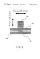
- FIG. 2shows a configuration of a magnetic head incorporated in a common hard disk drive and is a plan view seen from the face of the magnetic head that opposes a magnetic disk.
- the magnetic headcomprises a recording head formed of a pole 22 at a trailing edge and a pole 23 at a leading edge, a reproducing element 21 , and a lower shield 24 .
- a head-gap length directionis defined as the direction in which the lower shield 24 , the reproducing apparatus 21 , and the poles 23 and 22 are arranged sequentially.
- a head-gap width directionis defined as the direction perpendicular thereto.
- FIG. 1is a plan view showing a schematic configuration of a common hard disk drive.
- FIG. 1when a magnetic head 11 mounted on a head suspension 13 scans tracks on a magnetic disk, the magnetic head 11 is moved on an orbit shown by the alternating long and short dash line 17 in FIG. 1 by a voice coil motor 15 .
- the orbitgenerally has a circular-arc shape taken with a rotation axis 18 of a head actuator as its center.
- the tangential direction at arbitrary points on the circular arcsubstantially coincides with the head-gap width direction. This tangential direction is defined as the “track-scanning direction”.
- FIG. 3is an enlarged view of a part of a recording track on a magnetic disk 12 .
- the magnetized direction of bits 31 recorded in the magnetic disk 12coincides with the head-gap length direction and is perpendicular at every portion to the head-gap width length, i.e. the track-scanning direction of the magnetic head 11 .
- the magnetized direction of a ferromagnetic film pattern formed on the master information carrier and the head-gap length directioncoincide with each other in preformat recording. That is to say, it is preferable that the magnetized direction of the ferromagnetic film is perpendicular at every portion to the track-scanning direction of the magnetic head in every track on the magnetic disk.
- the magnetic headdetects the change in magnetization in the head-gap length direction.
- track-scanningmeans the scanning performed across tracks.
- a device for applying a magnetic field used for recording preformat information signalscan adjust the applied magnetic field to correspond to a circular-arc orbit of the magnetic head in track-scanning.
- the present inventionaims to solve the aforementioned problems in the prior art. It is an object of the present invention to provide a master-information magnetic recording apparatus enabling highly reliable preformat recording. In more detail, the object is to provide the master-information magnetic recording apparatus in which when magnetizing a ferromagnetic film pattern formed on a master information carrier, the magnetizing direction of recording bits of the ferromagnetic film pattern coincides with a head-gap length direction of a magnetic head in a magnetic recording/reproducing apparatus.
- the master-information magnetic recording apparatushas a construction as follows:
- the apparatushas a construction for recording predetermined information signals into a magnetic recording medium having a ferromagnetic layer, by using a master information carrier comprising a substrate on which a ferromagnetic film pattern corresponding to predetermined information signals is formed.
- the apparatuscomprises a support for holding a magnetic recording medium in contact with the master information carrier; and means for applying a magnetic field to the master information carrier to magnetize the ferromagnetic film pattern.
- the direction of the applied magnetic fieldbeing perpendicular to a circular-arc path on the magnetic recording medium along which a magnetic head scans tracks in a magnetic recording/reproducing apparatus into which the magnetic recording medium is installed.
- Such a constructionallows the magnetized direction of the recorded bits of the preformat information signals on the magnetic recording medium to coincide with the head-gap length direction of the magnetic head in the magnetic recording/reproducing apparatus, thus enabling the preformat recording that permits sufficient reproduction amplitude for track-scanning by the magnetic head in the magnetic recording/reproducing apparatus to be obtained.
- the device for applying a magnetic fieldcan be a bar-like permanent magnet with a center axis curved along the circular-arc orbit and its magnetizing direction perpendicular to the center axis.
- the device for applying a magnetic fieldcan be a large magnetic head having a pair of bar-like magnetic bodies opposing each other, between which a center axis curved along the circular-arc orbit is located, and a coil wound around at least one of the bar-like magnetic bodies, and its magnetizing direction is perpendicular to the center axis.
- Both the constructions mentioned aboveallow the magnetized direction of the recorded bits of the preformat information signals on the magnetic recording medium to coincide with the head-gap length direction, thus enabling the preformat recording that permits sufficient reproduction amplitude for track-scanning by the magnetic head in the magnetic recording/reproducing apparatus to be obtained.
- FIG. 1is a plan view showing a schematic configuration of a common hard disk drive
- FIG. 2is a plan view showing a schematic configuration of a magnetic head for recording and reproducing information signals provided in the hard disk drive;
- FIG. 3is a view showing the magnetized direction of recorded bits on a hard disk and a track-scanning direction of the magnetic head for recording and reproduction provided in the hard disk drive;
- FIG. 4is a plan view showing a schematic configuration of a master information carrier in a first embodiment of the present invention
- FIG. 5is a view showing an example of embossed patterns corresponding to preformat information signals formed on a surface of the master information carrier
- FIG. 6is a cross-sectional view showing a master-information magnetic recording apparatus in the first embodiment of the present invention.
- FIG. 7is a perspective view showing the principal recording portion of the recording apparatus shown in FIG. 6, including a cross section of a part thereof;
- FIG. 8is a perspective view showing an example of methods of initial magnetization of a magnetic recording medium into which information signals are recorded using the recording apparatus shown in FIG. 6;
- FIG. 9is a plan view showing a schematic configuration of a master information carrier in a second embodiment of the present invention.
- FIG. 10is a cross-sectional view showing the master-information magnetic recording apparatus in the second embodiment of the present invention.
- FIG. 11is a perspective view showing the principal recording portion of the recording apparatus shown in FIG. 10, including a cross section of a part thereof.
- FIG. 12is a perspective view showing an example of methods of initial magnetization of a magnetic recording medium into which information signals are recorded using the recording apparatus shown in FIG. 10 .
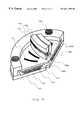
- FIG. 6is a cross-sectional view showing a master-information magnetic recording apparatus of a first embodiment according to the present invention.
- a circular recessed portion 63 ais formed at the center of a lower plate 63 .
- a circular elastic plate 67is placed in the recessed portion 63 a .
- a hard disk 61is positioned, and a master information carrier 62 is placed on the hard disk 61 .
- Center holes 61 a and 67 aare formed at the centers of the hard disk 61 and the elastic plate 67 , respectively.
- a suction pipe 68is connected to the lower plate 63 at its center, and is continuous with the center hole 61 a of the hard disk 61 and the center hole 67 a of the elastic plate 67 .
- An air suction device 69is provided at an end of the suction pipe 68 .
- the air suction device 69starts operating, the master information carrier 62 is drawn toward the hard disk 61 , since air between the master information carrier 62 and the hard disk 61 is sucked out.
- An upper flange 64presses the upper surface of the master information carrier 62 at the periphery, resulting in a uniform contact between the hard disk 61 and the master information carrier 62 .
- the lower plate 63 and the upper flange 64are fixed with bolts 65 .
- a numeral 66denotes a permanent magnet as a device for applying a magnetic field. Using this permanent magnet 66 , preformat information signals are recorded into the hard disk 61 .
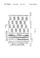
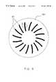
- areas 41are provided on the surface of the master information carrier 62 and are spaced at a predetermined angular interval.
- the areas 41have a fine embossed pattern formed corresponding to the preformat information signals.
- An area A of a part of the areas 41 in FIG. 4is shown in FIG. 5 in an enlarged scale.
- the embossed patterns corresponding to a tracking servo signal, an address data signal, and a reproduction clock signalare arranged sequentially in the track-circumferential direction.
- the embossed patternsalso are arranged transversely to the track-circumferential direction and along a track-scanning orbit of a magnetic head in a magnetic recording/reproducing apparatus.
- parts shown with hatchingare protruding portions and their surfaces are formed of a ferromagnetic material such as Co.
- a method of forming the fine embossed pattern corresponding to the information signals on the surface of the master information carrierwill be explained as follows.
- a ferromagnetic film made of Co or the likeis formed on a surface of a glass substrate with a fine surface roughness and an excellent flatness by a sputtering method.
- a resist filmis exposed and developed by a photolithographic method or another lithographic technique using a laser beam or an electron beam.
- an embossed patternis formed by dry etching or the like.
- the embossed patternalso can be formed by a so-called lift-off technology in which a resist film is formed on a surface of a glass substrate and is patterned, a ferromagnetic film made of Co or the like is formed, and then the resist film is removed.
- the method of forming the embossed pattern on the surface of the master information carrieris not limited to the aforementioned methods.
- the fine embossed patternmay be formed directly by using a laser, electron beam, or ion beam, or by machining.
- the method of forming the ferromagnetic film on the surface of the glass substratealso is not limited to the sputtering method.
- general methods of forming thin films that have been practicedsuch as vacuum deposition, ion plating, CVD, plating, or the like can be employed.
- the material of the ferromagnetic film for forming the surfaces of the protruding portions of the embossed pattern on the master information carrier 62is not limited to Co. Many kinds of magnetic materials can be used regardless of whether the material is a hard-magnetic material, a semihard magnetic material, or a soft magnetic material. In order to generate a sufficient recording magnetic field independently of the kind of magnetic recording medium into which master information signals are recorded, materials with higher saturation magnetic flux density are preferred. Particularly, in a magnetic disk with a high coercive force over 2000 oersted and a flexible disk with a thick magnetic layer, sufficient recording cannot be performed at a saturation magnetic flux density of 0.8 tesla or less in some cases. Therefore, magnetic materials with a saturation magnetic flux density of at least 0.8 tesla, preferably at least 1.0 tesla, are generally used.
- the recessed portions of embossed pattern formed by the ferromagnetic film on the master information carrier 62are preferably filled with non-magnetic solid material.
- the edge portions of the ferromagnetic filmare protected thereby. That is, partial stress applied to the edges of the pattern of the ferromagnetic film when the master information carrier is contacted securely and repeatedly with magnetic disks for recording by using the atmospheric pressure is relieved.
- the ferromagnetic filmcan be prevented from being chipped.
- one master information carriercan be used for the recording of a considerable number of disks compared to conventional master information carriers, and thus, the life of the master information carrier can be extended. Further, the master information carrier can have a longer life by forming a hard protective film on the ferromagnetic film and non-magnetic solid material.
- the recording apparatusis designed so that when magnetizing the ferromagnetic film on the protruding portions of the embossed pattern (a master information pattern) formed on the master information carrier 62 to record preformat information signals into the hard disk 61 as a magnetic recording medium, the direction of magnetizing the ferromagnetic film on the protruding portions coincides with the head-gap length direction of a magnetic head in a magnetic recording/reproducing apparatus. Substantially, the head-gap length direction is perpendicular to the track-scanning direction of the magnetic head in the magnetic recording/reproducing apparatus. Therefore, the direction of magnetizing the ferromagnetic film on the protruding portions is made perpendicular to the track-scanning direction of the magnetic head in the magnetic recording/reproducing apparatus.
- FIG. 7is a perspective view showing a part of the master-information magnetic recording apparatus shown in FIG. 6 .
- the permanent magnet 66 used for recording preformat information signalshas a sectored face opposing the master information carrier 62 .
- a side 66 b of the sectored facehas a circular-arc shape extending along the track-scanning orbit of the magnetic head in the magnetic recording/reproducing apparatus.
- the magnetizing direction of the permanent magnet 66is parallel to the surface of the master information carrier 62 and perpendicular to the side 66 b at every portion.
- the use of the permanent magnet 66allows the ferromagnetic film on the protruding portions of the master information carrier 62 to be magnetized in the direction perpendicular to the track-scanning direction of the magnetic head in the magnetic recording/reproducing apparatus over all of the tracks. That is to say, the ferromagnetic film is magnetized in the same direction as the head-gap length direction of the magnetic head in the magnetic recording/reproducing apparatus.
- an atmospheric pressureis utilized for bringing the hard disk 61 and the master information carrier 62 into close contact with each other, which are mechanically pressed further to contact with each other using bolts 65 , thus ensuring an entire and uniform contact between them.
- the ferromagnetic film on the protruding portions of the embossed patterns formed on the master information carrier 62is magnetized using the permanent magnet 66 , thus recording the preformat information signals corresponding to the embossed pattern into the hard disk 61 .
- the recording processwill be explained further in detail as follows.
- initial magnetizationis carried out.
- a permanent magnet 81is rotated in parallel to the hard disk 61 about a center axis 82 of the hard disk 61 , which is indicated with an alternating long and short dash line, with the permanent magnet 81 being positioned close to the hard disk 61 , thus initializing the hard disk 61 (initial magnetization).
- the permanent magnet 81has the same shape as that of the permanent magnet 66 used in recording preformat information signals.
- the magnetizing direction 82 of the permanent magnet 81may be the same as or opposite to the magnetizing direction 66 a of the permanent magnet 66 . In the first embodiment, the magnetizing direction 82 is opposite to the magnetizing direction 66 a.
- the elastic plate 67 , the hard disk 61 , and the master information carrier 62are then superposed on the lower plate 63 sequentially so that the surface of the master information carrier 62 on which the embossed pattern is formed and the hard disk 61 come into contact with each other.
- the air suction device 69is started. Air between the master information carrier 62 and the hard disk 61 is sucked out through the center hole 61 a of the hard disk 61 and the center hole 67 a of the elastic plate 67 , and therefore the master information carrier 62 is forced toward the hard disk 61 . An atmospheric pressure acts on the center portion of the master information carrier 62 . In this condition, only the vicinity of the center portion of the master information carrier 62 is securely in contact with the hard disk 61 , and the master information carrier 62 and the hard disk 61 may not be in secure contact with each other at their periphery.
- the upper flange 64is placed on the upper surface of the master information carrier 62 at the periphery.
- the upper flange 64 and the lower plate 63are fixed with the bolts 65 .
- the permanent magnet 66is rotated in parallel to the master information carrier 62 about the alternating long and short dash line shown in FIG. 6 as the rotation center, thus applying a direct excition magnetic field to the entire surface of the master information carrier 62 . Consequently, the ferromagnetic film on the protruding portions of the master information carrier 62 is magnetized, thus recording preformat information signals corresponding to the embossed pattern into the hard disk 61 .
- the direction of the magnetic field generated from the permanent magnet 66is perpendicular to the track-scanning orbit of the magnetic head in the magnetic recording/reproducing apparatus. Therefore, in magnetizing the ferromagnetic film on the protruding portions of the master information carrier 62 , its magnetized direction and the head-gap length direction of the magnetic head in the magnetic recording/reproducing apparatus are allowed to coincide with each other. As a result, it enables preformat recording that permits sufficient reproduction amplitude for track-scanning by the magnetic head in the magnetic recording/reproducing apparatus to be obtained.
- the mechanism for holding and rotating the permanent magnet 66 or 81is omitted in the figures.
- a mechanism suitably selected from generally used methodscan be used.
- FIG. 10is a cross-sectional view showing a master-information magnetic recording apparatus of a second embodiment according to the present invention.
- a circular recessed portion 103 ais formed at the center of a lower plate 103 .
- a circular elastic plate 107is placed in the recessed portion 103 a .
- On the elastic plate 107a hard disk 101 is positioned, and a master information carrier 102 is placed on the hard disk 101 .
- Center holes 101 a and 107 aare formed at the centers of the hard disk 101 and the elastic plate 107 , respectively.
- a suction pipe 108is connected to the lower plate 103 at its center, and is continuous with the center hole 101 a of the hard disk 101 and the center hole 107 a of the elastic plate 107 .
- An air suction device 109is provided at an end of the suction pipe 108 .
- the air suction device 109starts operating, the master information carrier 102 is drawn toward the hard disk 101 , since air between the master information carrier 102 and the hard disk 101 is sacked out.
- An upper flange 104presses the upper surface of the master information carrier 102 at the periphery, resulting in a uniform contact between the hard disk 101 and the master information carrier 102 .
- the lower plate 103 and the upper flange 104are fixed with bolts 105 .
- a numeral 106denotes a large magnetic head provided in a device for applying a magnetic field. Using the large magnetic head 106 , preformat information signals are recorded into the hard disk 101 .
- areas 91are provided on the surface of the master information carrier 102 and are spaced at a predetermined angular interval.
- the areas 91have a fine embossed pattern formed corresponding to the preformat information signals.
- a concrete example of the embossed pattern formed in the areas 91is the same as in the first embodiment as shown in FIG. 5 .
- Such embossed patternis formed by the same process as that described in the first embodiment.
- the recording apparatusis designed so that when magnetizing the ferromagnetic film on the protruding portions of the embossed pattern formed on a master information carrier 92 to record preformat information signals into the hard disk 101 , the direction of magnetizing a ferromagnetic film on the protruding portions coincides with the head-gap length direction of a magnetic head (hereafter referred to as a “recording/reproducing magnetic head”) provided in a magnetic recording/reproducing apparatus for reproducing the information signals recorded in a magnetic recording medium.
- the head-gap length directionis perpendicular to the track-scanning direction of the recording/reproducing magnetic head. Therefore, the direction of magnetizing the ferromagnetic film on the protruding portions is made perpendicular to the track-scanning direction of the recording/reproducing magnetic head.
- FIG. 11is a perspective view showing a part of the master-information magnetic recording apparatus shown in FIG. 10 .
- the large magnetic head 106 used for recording preformat information signalsis formed of a magnetic core half body 106 a with a coil 106 d and a magnetic core half body 106 b that are arranged opposing each other to provide a gap 106 c .
- Application of current to the coil 106 dgenerates a magnetic field 106 e toward the magnetic core half body 106 b from the magnetic core half body 106 a at the gap 106 c , as shown with an arrow 106 e .
- the gap 106 chas a circular-arc shape being along a track-scanning orbit of the recording/reproducing magnetic head on the face opposing the master information carrier 102 .
- Each of magnetic core half bodies 106 a and 106 bhas a sectored face opposing the master information carrier 102 .
- One side of each sectored facehas a circular-arc shape being along a track-scanning orbit of the recording/reproducing magnetic head. Therefore, the direction of the magnetic field 106 e generated at the gap 106 c is perpendicular to the track-scanning orbit at every portion.
- the use of the large magnetic head 106allows the ferromagnetic film on the protruding portions of the master information carrier 102 to be magnetized in the direction perpendicular to the track-scanning direction of the recording/reproducing magnetic head over all of the tracks. That is to say, the ferromagnetic film is magnetized in the same direction as the head-gap length direction of the recording/reproducing magnetic head.
- an atmospheric pressureis utilized for bringing the hard disk 101 and the master information carrier 102 into contact with each other, which are mechanically pressed further to contact with each other, thus ensuring an entire and uniform contact between them. Then, the ferromagnetic film on the protruding portions of the embossed pattern formed on the master information carrier 102 is magnetized using the second magnetic head 106 , thus recording preformat information signals corresponding to the embossed pattern into the hard disk 101 .
- the recording processwill be explained in detail as follows.
- initial magnetizationis carried out. As shown in FIG. 12, electric current is applied to the coil 121 a and a large magnetic head 121 is rotated in parallel to the hard disk 101 about a center axis 122 of the hard disk 101 , which is indicated with an alternating long and short dash line, with the gap 121 b being positioned close to the hard disk 101 , thus initializing the hard disk 101 (initial magnetization).
- the large magnetic head 121may be replaced with the permanent magnet 81 as shown in FIG. 8 .
- the large magnetic head 121may have the same shape as that of the large magnetic head 106 used in recording preformat information signals.
- the direction of the magnetic field generated at the gap 121 b of the large magnetic head 121may be the same as or opposite to that of the magnetic field in recording the preformat information signals. In the second embodiment, they are opposite.
- the direction of the magnetic field generated at the gap 121 bis determined depending on the direction for applying the current to the coil 121 a . Therefore, in the second embodiment, the direction of the current applied to the coil provided for the large magnetic head 106 used in recording preformat information signals is opposite to that of the current applied to the coil 121 a.
- the elastic plate 107 and the hard disk 101are superposed on the lower plate 103 sequentially so that the face of the master information carrier 102 on which the embossed pattern are formed and the hard disk 101 are in contact with each other.
- the air suction device 109is started. Air between the master information carrier 102 and the hard disk 101 is sucked out through the center hole 101 a of the hard disk 101 and the center hole 107 a of the elastic plate 107 , and therefore the master information carrier 102 is forced toward the hard disk 101 . An atmospheric pressure acts on the center portion of the master information carrier 102 . In this condition, only the vicinity of the center portion of the master information carrier 102 is securely in contact with the hard disk 101 , and the master information carrier 102 and the hard disk 101 may not be in secure contact with each other at their periphery.
- the upper flange 104is placed on the upper surface of the master information carrier 102 at the periphery.
- the upper flange 104 and the lower plate 103are fixed with the bolts 105 .
- the large magnetic head 106is rotated in parallel to the master information carrier 102 about the alternating long and short dash line shown in FIG. 10, thus applying a direct excition magnetic field to the master information carrier 102 . Consequently, the ferromagnetic film on the protruding portions of the master information carrier 102 is magnetized, thus recording preformat information signals corresponding to the embossed pattern into the hard disk 101 .
- the direction of the magnetic field generated at the gap in the large magnetic head 106is perpendicular to the track-scanning orbit of the recording/reproducing magnetic head provided in the magnetic recording/reproducing apparatus. Therefore, in magnetizing the ferromagnetic film on the protruding portions of the master information carrier 102 , its magnetized direction and the head-gap length direction of the recording/reproducing magnetic head are allowed to coincide with each other. It enables the preformat recording that permits sufficient reproduction amplitude for track-scanning by the recording/reproducing magnetic head to be obtained.
- the magnetized direction of recorded bits of preformat information signals in a magnetic recording mediumcan coincide with a head-gap length direction of a magnetic head provided in a magnetic recording/reproducing apparatus for reproducing the information signals recorded in the magnetic recording medium. It enables the preformat recording that permits sufficient reproduction amplitude for track-scanning by the recording/reproducing magnetic head to be obtained.
Landscapes
- Engineering & Computer Science (AREA)
- Signal Processing (AREA)
- Magnetic Record Carriers (AREA)
- Recording Or Reproducing By Magnetic Means (AREA)
Abstract
Description
Claims (4)
Applications Claiming Priority (3)
| Application Number | Priority Date | Filing Date | Title |
|---|---|---|---|
| JP10-074670 | 1998-03-23 | ||
| JP07467098AJP3361740B2 (en) | 1998-03-23 | 1998-03-23 | Master information magnetic recording device and method of manufacturing magnetic recording medium |
| PCT/JP1999/001375WO1999049456A1 (en) | 1998-03-23 | 1999-03-18 | Master information magnetic recorder |
Publications (1)
| Publication Number | Publication Date |
|---|---|
| US6611388B1true US6611388B1 (en) | 2003-08-26 |
Family
ID=13553912
Family Applications (1)
| Application Number | Title | Priority Date | Filing Date |
|---|---|---|---|
| US09/646,138Expired - Fee RelatedUS6611388B1 (en) | 1998-03-23 | 1999-03-18 | Master information magnetic recorder |
Country Status (5)
| Country | Link |
|---|---|
| US (1) | US6611388B1 (en) |
| JP (1) | JP3361740B2 (en) |
| CN (1) | CN1208759C (en) |
| MY (1) | MY123255A (en) |
| WO (1) | WO1999049456A1 (en) |
Cited By (8)
| Publication number | Priority date | Publication date | Assignee | Title |
|---|---|---|---|---|
| US20020018312A1 (en)* | 2000-08-11 | 2002-02-14 | Masaki Hamamoto | Magnetic signal recording method and magnetic recording-reproduction apparatus |
| US20020159177A1 (en)* | 2001-02-01 | 2002-10-31 | Fuji Photo Film Co., Ltd. | Magnetic transfer method and apparatus |
| US20030142427A1 (en)* | 2002-01-31 | 2003-07-31 | Matsushita Electric Industrial Co., Ltd. | Master information magnetic recording apparatus and method for manufacturing magnetic recording medium in which information is recorded by using this |
| US20030161222A1 (en)* | 2002-02-26 | 2003-08-28 | Fuji Photo Film Co., Ltd. | Method of producing master information carrier for magnetic transfer |
| WO2006030928A1 (en)* | 2004-09-15 | 2006-03-23 | Fujifilm Corporation | Magnetic transfer holder unit, transfer apparatus, method of manufacturing a transfer medium, and magnetic recording medium |
| US7046476B1 (en) | 2005-01-10 | 2006-05-16 | Hitachi Global Storage Technologies | Method apparatus and system for accessing discontinuous media tracks |
| US7312939B2 (en) | 2005-02-25 | 2007-12-25 | Hitachi Global Storage Technologies Netherlands Bv | System, method, and apparatus for forming a patterned media disk and related disk drive architecture for head positioning |
| EP1184846A3 (en)* | 2000-08-14 | 2008-03-26 | FUJIFILM Corporation | Method of magnetically transferring information signal from master medium to slave medium |
Families Citing this family (12)
| Publication number | Priority date | Publication date | Assignee | Title |
|---|---|---|---|---|
| SG92772A1 (en)* | 2000-03-29 | 2002-11-19 | Fuji Photo Film Co Ltd | Method and apparatus for magnetic transfer |
| SG92760A1 (en)* | 2000-03-29 | 2002-11-19 | Fuji Photo Film Co Ltd | Magnetic transfer method and system |
| SG92774A1 (en)* | 2000-03-29 | 2002-11-19 | Fuji Photo Film Co Ltd | Method and apparatus for magnetic transfer |
| SG92773A1 (en)* | 2000-03-29 | 2002-11-19 | Fuji Photo Film Co Ltd | Method and apparatus for magnetic transfer |
| US7057834B2 (en) | 2000-03-31 | 2006-06-06 | Matsushita Electric Industrial Co., Ltd. | Master information carrier and method for manufacturing magnetic disc using the same |
| CN1174380C (en) | 2000-03-31 | 2004-11-03 | 松下电器产业株式会社 | Master disk and magnetic disk manufacturing method using the same |
| SG98008A1 (en)* | 2000-06-09 | 2003-08-20 | Fuji Photo Film Co Ltd | Method and apparatus for magnetic transfer |
| US6794062B2 (en)* | 2001-01-22 | 2004-09-21 | Fuji Photo Film Co., Ltd. | Magnetic transfer master medium |
| CN1253858C (en)* | 2001-06-15 | 2006-04-26 | 富士胶片株式会社 | Magnetic transfer device |
| JP2003123247A (en)* | 2001-10-15 | 2003-04-25 | Fuji Photo Film Co Ltd | Magnetic transfer device |
| JP2003248922A (en)* | 2002-02-25 | 2003-09-05 | Fuji Photo Film Co Ltd | Magnetic transfer method |
| KR20040080340A (en)* | 2003-03-07 | 2004-09-18 | 후지 샤신 필름 가부시기가이샤 | Magnetic transfer apparatus |
Citations (88)
| Publication number | Priority date | Publication date | Assignee | Title |
|---|---|---|---|---|
| US3381085A (en) | 1962-05-09 | 1968-04-30 | Minnesota Mining & Mfg | Duplication of video disc recordings |
| US3641280A (en) | 1970-01-19 | 1972-02-08 | Bell & Howell Co | Apparatus for contact copying magnetic records including shield for preventing erasure of the master record |
| JPS4853704A (en) | 1971-11-05 | 1973-07-28 | ||
| JPS495610A (en) | 1972-05-04 | 1974-01-18 | ||
| US3844907A (en) | 1970-03-27 | 1974-10-29 | Fuji Photo Film Co Ltd | Method of reproducing magnetization pattern |
| US3869711A (en) | 1973-09-24 | 1975-03-04 | Ibm | Magnetic pattern recording |
| JPS5125723A (en) | 1974-08-28 | 1976-03-02 | Hitachi Ltd | DENKISHADENKISEIDOSEIGYOSOCHI |
| US3982276A (en) | 1971-10-21 | 1976-09-21 | U.S. Philips Corporation | Method of copying magnetic recordings provided on a magnetizable medium having a greater coercive force before than after recording |
| US4071869A (en) | 1976-06-01 | 1978-01-31 | International Business Machines Corporation | Assembling flexible disk record structures |
| JPS5512545A (en) | 1978-07-11 | 1980-01-29 | Sony Corp | Magnetic recording media |
| JPS5570935A (en) | 1978-11-24 | 1980-05-28 | Toshiba Corp | Manufacture for magnetic recording media |
| JPS567243A (en) | 1979-07-02 | 1981-01-24 | Toshiba Corp | Magnetic transfer recording system |
| JPS5622219A (en) | 1979-07-31 | 1981-03-02 | Fujitsu Ltd | Manufacture of magnetic recording medium |
| JPS5641528A (en) | 1979-09-13 | 1981-04-18 | Toshiba Corp | Magnetic transfering and recording system |
| JPS5668926A (en) | 1979-11-09 | 1981-06-09 | Tdk Corp | Magnetic recording medium |
| US4277806A (en) | 1979-05-14 | 1981-07-07 | Eastman Technology, Inc. | Magnetic recording using recording media having temperature dependent coercivity |
| JPS578921A (en) | 1980-06-19 | 1982-01-18 | Nec Corp | Magnetic recording body |
| JPS5724032A (en) | 1980-07-21 | 1982-02-08 | Toshiba Corp | Magnetic transfer recording system |
| JPS57109134A (en) | 1980-12-26 | 1982-07-07 | Toshiba Corp | Magnetic transferring and recording method |
| JPS57109133A (en) | 1980-12-26 | 1982-07-07 | Toshiba Corp | Magnetic transfering and recording system |
| JPS57138061A (en) | 1981-02-17 | 1982-08-26 | Matsushita Electric Ind Co Ltd | Magnetic transferring system |
| JPS57158038A (en) | 1981-03-24 | 1982-09-29 | Toshiba Corp | Magnetic transfer recorder |
| JPS57158004A (en) | 1981-03-24 | 1982-09-29 | Toshiba Corp | Magnetic transfer recorder |
| JPS57158040A (en) | 1981-03-24 | 1982-09-29 | Toshiba Corp | Magnetic transfer recorder |
| JPS57158041A (en) | 1981-03-24 | 1982-09-29 | Toshiba Corp | Magnetic transfer recorder |
| JPS57158039A (en) | 1981-03-24 | 1982-09-29 | Toshiba Corp | Magnetic transfer recorder |
| US4363038A (en) | 1980-07-14 | 1982-12-07 | Minnesota Mining And Manufacturing Company | Contact duplication system using anisotropic magnetic recording media |
| JPS5826328A (en) | 1981-08-11 | 1983-02-16 | Matsushita Electric Ind Co Ltd | Magnetic tape transfer method |
| JPS5894136A (en) | 1981-11-30 | 1983-06-04 | Toshiba Corp | Magnetic transferring recorder |
| JPS5894137A (en) | 1981-11-30 | 1983-06-04 | Toshiba Corp | magnetic transfer recording device |
| US4422106A (en) | 1979-07-02 | 1983-12-20 | Tokyo Shibaura Denki Kabushiki Kaisha | Magnetic transcription-recording method |
| EP0131985A1 (en) | 1983-06-22 | 1985-01-23 | Koninklijke Philips Electronics N.V. | Device for closing the loading aperture of a washing machine |
| JPS6022733A (en) | 1983-07-19 | 1985-02-05 | Hitachi Metals Ltd | Substrate for magnetic disc |
| JPS60209915A (en) | 1984-04-02 | 1985-10-22 | Nec Corp | Servo signal recording method |
| GB2164483A (en) | 1984-09-10 | 1986-03-19 | Victor Company Of Japan | Method for recording servo control signals on a magnetic disc |
| JPS61190719A (en) | 1985-02-19 | 1986-08-25 | Sharp Corp | magnetic disk |
| JPS62124622A (en) | 1985-11-25 | 1987-06-05 | Toshiba Glass Co Ltd | Vertically magnetized film for glass plate |
| USRE32464E (en) | 1971-05-03 | 1987-07-28 | Thin film recording and method of making | |
| JPS62208430A (en) | 1986-03-07 | 1987-09-12 | Toshiba Corp | magnetic transfer device |
| JPS62264432A (en) | 1986-05-09 | 1987-11-17 | Konika Corp | Manufacture of magnetic recording medium provided with sputtered protecting layer |
| JPS63811A (en) | 1986-06-19 | 1988-01-05 | Seiko Epson Corp | Servo pattern writing device |
| US4725899A (en) | 1985-02-25 | 1988-02-16 | Gardner John P | Reproduction of magnetic recordings |
| JPS63166023A (en) | 1986-12-27 | 1988-07-09 | Toshiba Corp | Magnetic transfer device |
| JPS63175229A (en) | 1987-01-14 | 1988-07-19 | Toshiba Corp | Magnetic transfer method |
| JPS63183623A (en) | 1987-01-23 | 1988-07-29 | Sony Corp | Method for contact magnetic field transfer to flexible disk |
| JPS6488921A (en) | 1987-09-29 | 1989-04-03 | Toshiba Corp | Magnetic transferring device |
| US4912585A (en) | 1988-04-28 | 1990-03-27 | International Business Machines Corporation | Discrete track thin film magnetic recording disk with embedded servo information |
| US4911967A (en) | 1986-02-11 | 1990-03-27 | Commissariat A L'energie Atomique | Substrate for magnetic disk memory and production process |
| JPH0294111A (en) | 1988-09-30 | 1990-04-04 | Sekisui Chem Co Ltd | Magnetic recording medium |
| JPH0298820A (en) | 1988-10-05 | 1990-04-11 | Fujitsu Ltd | Manufacturing method of perpendicular magnetic disk |
| JPH02132630A (en) | 1988-11-11 | 1990-05-22 | Sekisui Chem Co Ltd | Magnetic recording medium |
| JPH02214023A (en) | 1989-02-14 | 1990-08-27 | Fujitsu Ltd | Production of perpendicular magnetic disk |
| JPH02301018A (en) | 1989-05-16 | 1990-12-13 | Sony Corp | Magnetic recording medium |
| US5032931A (en) | 1987-01-19 | 1991-07-16 | Kabushiki Kaisha Toshiba | Method for magnetic transfer and apparatus therefor |
| US5049942A (en) | 1988-04-07 | 1991-09-17 | Olin Corporation | Electrostatic transfer device |
| WO1991016706A1 (en) | 1990-04-17 | 1991-10-31 | Hitachi Maxell, Ltd. | Method of producing magnetic disks having signals |
| JPH03256223A (en) | 1990-03-06 | 1991-11-14 | Sony Corp | Magnetic transfering method |
| JPH0413220A (en) | 1990-05-01 | 1992-01-17 | Sony Corp | Magnetic transferring method |
| JPH04134629A (en) | 1990-09-26 | 1992-05-08 | Toshiba Corp | Transfer method for magnetic disk |
| US5121258A (en) | 1991-08-12 | 1992-06-09 | Eastman Kodak Company | Apparatus for anhysteretic duplication of a flexible magnetic disk |
| JPH04251440A (en) | 1990-12-28 | 1992-09-07 | Sony Corp | Disk transfer device |
| JPH04251435A (en) | 1990-12-28 | 1992-09-07 | Tdk Corp | Magnetic disk |
| US5296995A (en) | 1989-01-11 | 1994-03-22 | Hitachi, Ltd. | Method of magnetically recording and reading data, magnetic recording medium, its production method and magnetic recording apparatus |
| US5353169A (en) | 1991-02-11 | 1994-10-04 | Eastman Kodak Company | Contact duplication of magnetically recorded information without the use of a transfer field |
| JPH0744858A (en) | 1993-07-30 | 1995-02-14 | Victor Co Of Japan Ltd | Magnetic recording and reproducing medium and magnetic recording medium for contact transfer mother tape |
| JPH0778337A (en) | 1993-09-10 | 1995-03-20 | Sony Corp | Magnetic recording and transfer device |
| EP0655734A1 (en) | 1993-11-30 | 1995-05-31 | Sony Corporation | A magnetic disc substrate and a magnetic disc using the same |
| US5426535A (en) | 1993-07-29 | 1995-06-20 | Eastman Kodak Company | Apparatus for removing air from between a master magnetic medium and a slave magnetic medium preceding anhysteretic transfer of signals from master to slave |
| JPH09138927A (en) | 1995-11-16 | 1997-05-27 | Sony Corp | Device for magnetizing magnetic disk and method therefor |
| JPH1040544A (en) | 1996-07-22 | 1998-02-13 | Matsushita Electric Ind Co Ltd | Method for recording master information carrier and master information signal on magnetic recording medium |
| US5748421A (en) | 1993-03-19 | 1998-05-05 | Brother Kogyo Kabushiki Kaisha | Magnetic recording disk |
| JPH10162360A (en) | 1996-12-04 | 1998-06-19 | Hitachi Maxell Ltd | Contact type magnetic transfer apparatus and magnetic transfer method |
| JPH10269566A (en) | 1997-03-27 | 1998-10-09 | Matsushita Electric Ind Co Ltd | Master information carrier and master information magnetic recording apparatus for recording information signal on magnetic recording medium using the same |
| JPH1125455A (en) | 1997-06-30 | 1999-01-29 | Matsushita Electric Ind Co Ltd | Magnetic transfer device |
| US5898553A (en) | 1996-05-20 | 1999-04-27 | Sony Corporation | Magnetic disk and magnetic disk unit |
| EP0915456A1 (en) | 1996-07-22 | 1999-05-12 | Matsushita Electric Industrial Co., Ltd | Master information carrier, process for producing the carrier, and method and apparatus for recording master information signal on magnetic recording medium by using the carrier |
| JPH11175973A (en) | 1997-12-08 | 1999-07-02 | Matsushita Electric Ind Co Ltd | Master information magnetic recording device |
| US5991104A (en) | 1996-11-27 | 1999-11-23 | Seagate Technology, Inc. | Using servowriter medium for quickly written servo-patterns on magnetic media |
| US6014296A (en) | 1995-07-24 | 2000-01-11 | Kabushiki Kaisha Toshiba | Magnetic disk, method of manufacturing magnetic disk and magnetic recording apparatus |
| US6088200A (en) | 1997-11-27 | 2000-07-11 | Sony Corporation | Magnetic disc and magnetic disc drive |
| JP2001014667A (en) | 1999-04-26 | 2001-01-19 | Fuji Photo Film Co Ltd | Magnetic transferring method and magnetic transferring device |
| EP1128363A2 (en) | 2000-02-28 | 2001-08-29 | Fuji Photo Film Co., Ltd. | Method for magnetic transfer |
| US6309802B1 (en) | 1991-12-17 | 2001-10-30 | Ronny Bar-Gadda | Disk medium |
| JP3256223B2 (en) | 1989-12-22 | 2002-02-12 | レオ・ファーマシューティカル・プロダクツ・リミテッド・エイ/エス(レーベンス・ケミスケ・ファブリック・プロデュクチオンスアクチーセルスカブ) | Novel vitamin D analog |
| US6376083B1 (en) | 1994-09-22 | 2002-04-23 | Fuji Photo Film, Ltd. | Magnetic recording medium |
| US20020054442A1 (en) | 2000-11-07 | 2002-05-09 | Fuji Photo Film Co., Ltd. | Method and device for magnetic transfer and magnetic recording medium |
| US6433944B1 (en) | 1998-09-25 | 2002-08-13 | Fuji Photo Film Co., Ltd. | Master carrier for magnetic transfer and method for transfer |
| US6469848B1 (en) | 1999-04-27 | 2002-10-22 | Matsushita Electric Industrial Co., Ltd. | Method and apparatus for manufacturing a magnetic recording medium with pre-format recording signals transferred and recorded by using a master information carrier |
Family Cites Families (1)
| Publication number | Priority date | Publication date | Assignee | Title |
|---|---|---|---|---|
| JPH10275435A (en)* | 1997-03-31 | 1998-10-13 | Toshiba Corp | Servo writing device and master disk applied to the device |
- 1998
- 1998-03-23JPJP07467098Apatent/JP3361740B2/ennot_activeExpired - Fee Related
- 1999
- 1999-03-18CNCN99804430.XApatent/CN1208759C/ennot_activeExpired - Fee Related
- 1999-03-18USUS09/646,138patent/US6611388B1/ennot_activeExpired - Fee Related
- 1999-03-18WOPCT/JP1999/001375patent/WO1999049456A1/ennot_activeCeased
- 1999-03-20MYMYPI99001055Apatent/MY123255A/enunknown
Patent Citations (93)
| Publication number | Priority date | Publication date | Assignee | Title |
|---|---|---|---|---|
| US3381085A (en) | 1962-05-09 | 1968-04-30 | Minnesota Mining & Mfg | Duplication of video disc recordings |
| US3641280A (en) | 1970-01-19 | 1972-02-08 | Bell & Howell Co | Apparatus for contact copying magnetic records including shield for preventing erasure of the master record |
| US3844907A (en) | 1970-03-27 | 1974-10-29 | Fuji Photo Film Co Ltd | Method of reproducing magnetization pattern |
| USRE32464E (en) | 1971-05-03 | 1987-07-28 | Thin film recording and method of making | |
| US3982276A (en) | 1971-10-21 | 1976-09-21 | U.S. Philips Corporation | Method of copying magnetic recordings provided on a magnetizable medium having a greater coercive force before than after recording |
| JPS4853704A (en) | 1971-11-05 | 1973-07-28 | ||
| JPS495610A (en) | 1972-05-04 | 1974-01-18 | ||
| US3869711A (en) | 1973-09-24 | 1975-03-04 | Ibm | Magnetic pattern recording |
| JPS5060212A (en) | 1973-09-24 | 1975-05-24 | ||
| JPS5125723A (en) | 1974-08-28 | 1976-03-02 | Hitachi Ltd | DENKISHADENKISEIDOSEIGYOSOCHI |
| US4071869A (en) | 1976-06-01 | 1978-01-31 | International Business Machines Corporation | Assembling flexible disk record structures |
| JPS5512545A (en) | 1978-07-11 | 1980-01-29 | Sony Corp | Magnetic recording media |
| JPS5570935A (en) | 1978-11-24 | 1980-05-28 | Toshiba Corp | Manufacture for magnetic recording media |
| US4277806A (en) | 1979-05-14 | 1981-07-07 | Eastman Technology, Inc. | Magnetic recording using recording media having temperature dependent coercivity |
| JPS567243A (en) | 1979-07-02 | 1981-01-24 | Toshiba Corp | Magnetic transfer recording system |
| US4422106A (en) | 1979-07-02 | 1983-12-20 | Tokyo Shibaura Denki Kabushiki Kaisha | Magnetic transcription-recording method |
| JPS5622219A (en) | 1979-07-31 | 1981-03-02 | Fujitsu Ltd | Manufacture of magnetic recording medium |
| JPS5641528A (en) | 1979-09-13 | 1981-04-18 | Toshiba Corp | Magnetic transfering and recording system |
| JPS5668926A (en) | 1979-11-09 | 1981-06-09 | Tdk Corp | Magnetic recording medium |
| JPS578921A (en) | 1980-06-19 | 1982-01-18 | Nec Corp | Magnetic recording body |
| US4363038A (en) | 1980-07-14 | 1982-12-07 | Minnesota Mining And Manufacturing Company | Contact duplication system using anisotropic magnetic recording media |
| JPS5724032A (en) | 1980-07-21 | 1982-02-08 | Toshiba Corp | Magnetic transfer recording system |
| JPS57109133A (en) | 1980-12-26 | 1982-07-07 | Toshiba Corp | Magnetic transfering and recording system |
| JPS57109134A (en) | 1980-12-26 | 1982-07-07 | Toshiba Corp | Magnetic transferring and recording method |
| JPS57138061A (en) | 1981-02-17 | 1982-08-26 | Matsushita Electric Ind Co Ltd | Magnetic transferring system |
| US4525828A (en) | 1981-03-24 | 1985-06-25 | Tokyo Shibaura Denki Kabushiki Kaisha | Optical magnetic recording device |
| JPS57158038A (en) | 1981-03-24 | 1982-09-29 | Toshiba Corp | Magnetic transfer recorder |
| JPS57158004A (en) | 1981-03-24 | 1982-09-29 | Toshiba Corp | Magnetic transfer recorder |
| JPS57158040A (en) | 1981-03-24 | 1982-09-29 | Toshiba Corp | Magnetic transfer recorder |
| JPS57158041A (en) | 1981-03-24 | 1982-09-29 | Toshiba Corp | Magnetic transfer recorder |
| JPS57158039A (en) | 1981-03-24 | 1982-09-29 | Toshiba Corp | Magnetic transfer recorder |
| JPS5826328A (en) | 1981-08-11 | 1983-02-16 | Matsushita Electric Ind Co Ltd | Magnetic tape transfer method |
| JPS5894137A (en) | 1981-11-30 | 1983-06-04 | Toshiba Corp | magnetic transfer recording device |
| JPS5894136A (en) | 1981-11-30 | 1983-06-04 | Toshiba Corp | Magnetic transferring recorder |
| EP0131985A1 (en) | 1983-06-22 | 1985-01-23 | Koninklijke Philips Electronics N.V. | Device for closing the loading aperture of a washing machine |
| JPS6022733A (en) | 1983-07-19 | 1985-02-05 | Hitachi Metals Ltd | Substrate for magnetic disc |
| JPS60209915A (en) | 1984-04-02 | 1985-10-22 | Nec Corp | Servo signal recording method |
| JPS6166215A (en) | 1984-09-10 | 1986-04-05 | Victor Co Of Japan Ltd | Recording system of tracking reference signal to magnetic recording medium disk |
| GB2164483A (en) | 1984-09-10 | 1986-03-19 | Victor Company Of Japan | Method for recording servo control signals on a magnetic disc |
| JPS61190719A (en) | 1985-02-19 | 1986-08-25 | Sharp Corp | magnetic disk |
| US4725899A (en) | 1985-02-25 | 1988-02-16 | Gardner John P | Reproduction of magnetic recordings |
| JPS62124622A (en) | 1985-11-25 | 1987-06-05 | Toshiba Glass Co Ltd | Vertically magnetized film for glass plate |
| US4911967A (en) | 1986-02-11 | 1990-03-27 | Commissariat A L'energie Atomique | Substrate for magnetic disk memory and production process |
| JPS62208430A (en) | 1986-03-07 | 1987-09-12 | Toshiba Corp | magnetic transfer device |
| JPS62264432A (en) | 1986-05-09 | 1987-11-17 | Konika Corp | Manufacture of magnetic recording medium provided with sputtered protecting layer |
| JPS63811A (en) | 1986-06-19 | 1988-01-05 | Seiko Epson Corp | Servo pattern writing device |
| JPS63166023A (en) | 1986-12-27 | 1988-07-09 | Toshiba Corp | Magnetic transfer device |
| JPS63175229A (en) | 1987-01-14 | 1988-07-19 | Toshiba Corp | Magnetic transfer method |
| US5032931A (en) | 1987-01-19 | 1991-07-16 | Kabushiki Kaisha Toshiba | Method for magnetic transfer and apparatus therefor |
| JPS63183623A (en) | 1987-01-23 | 1988-07-29 | Sony Corp | Method for contact magnetic field transfer to flexible disk |
| JPS6488921A (en) | 1987-09-29 | 1989-04-03 | Toshiba Corp | Magnetic transferring device |
| US5049942A (en) | 1988-04-07 | 1991-09-17 | Olin Corporation | Electrostatic transfer device |
| US4912585A (en) | 1988-04-28 | 1990-03-27 | International Business Machines Corporation | Discrete track thin film magnetic recording disk with embedded servo information |
| JPH0294111A (en) | 1988-09-30 | 1990-04-04 | Sekisui Chem Co Ltd | Magnetic recording medium |
| JPH0298820A (en) | 1988-10-05 | 1990-04-11 | Fujitsu Ltd | Manufacturing method of perpendicular magnetic disk |
| JPH02132630A (en) | 1988-11-11 | 1990-05-22 | Sekisui Chem Co Ltd | Magnetic recording medium |
| US5296995A (en) | 1989-01-11 | 1994-03-22 | Hitachi, Ltd. | Method of magnetically recording and reading data, magnetic recording medium, its production method and magnetic recording apparatus |
| JPH02214023A (en) | 1989-02-14 | 1990-08-27 | Fujitsu Ltd | Production of perpendicular magnetic disk |
| JPH02301018A (en) | 1989-05-16 | 1990-12-13 | Sony Corp | Magnetic recording medium |
| JP3256223B2 (en) | 1989-12-22 | 2002-02-12 | レオ・ファーマシューティカル・プロダクツ・リミテッド・エイ/エス(レーベンス・ケミスケ・ファブリック・プロデュクチオンスアクチーセルスカブ) | Novel vitamin D analog |
| US5303092A (en) | 1990-03-06 | 1994-04-12 | Sony Corporation | Magnetic transfer method |
| JPH03256223A (en) | 1990-03-06 | 1991-11-14 | Sony Corp | Magnetic transfering method |
| WO1991016706A1 (en) | 1990-04-17 | 1991-10-31 | Hitachi Maxell, Ltd. | Method of producing magnetic disks having signals |
| JPH0413220A (en) | 1990-05-01 | 1992-01-17 | Sony Corp | Magnetic transferring method |
| JPH04134629A (en) | 1990-09-26 | 1992-05-08 | Toshiba Corp | Transfer method for magnetic disk |
| JPH04251435A (en) | 1990-12-28 | 1992-09-07 | Tdk Corp | Magnetic disk |
| JPH04251440A (en) | 1990-12-28 | 1992-09-07 | Sony Corp | Disk transfer device |
| US5353169A (en) | 1991-02-11 | 1994-10-04 | Eastman Kodak Company | Contact duplication of magnetically recorded information without the use of a transfer field |
| US5121258A (en) | 1991-08-12 | 1992-06-09 | Eastman Kodak Company | Apparatus for anhysteretic duplication of a flexible magnetic disk |
| US6309802B1 (en) | 1991-12-17 | 2001-10-30 | Ronny Bar-Gadda | Disk medium |
| US5748421A (en) | 1993-03-19 | 1998-05-05 | Brother Kogyo Kabushiki Kaisha | Magnetic recording disk |
| US5426535A (en) | 1993-07-29 | 1995-06-20 | Eastman Kodak Company | Apparatus for removing air from between a master magnetic medium and a slave magnetic medium preceding anhysteretic transfer of signals from master to slave |
| JPH0744858A (en) | 1993-07-30 | 1995-02-14 | Victor Co Of Japan Ltd | Magnetic recording and reproducing medium and magnetic recording medium for contact transfer mother tape |
| JPH0778337A (en) | 1993-09-10 | 1995-03-20 | Sony Corp | Magnetic recording and transfer device |
| EP0655734A1 (en) | 1993-11-30 | 1995-05-31 | Sony Corporation | A magnetic disc substrate and a magnetic disc using the same |
| US5585989A (en) | 1993-11-30 | 1996-12-17 | Sony Corporation | Magnetic disc substrate and a magnetic disc using the same |
| US6376083B1 (en) | 1994-09-22 | 2002-04-23 | Fuji Photo Film, Ltd. | Magnetic recording medium |
| US6014296A (en) | 1995-07-24 | 2000-01-11 | Kabushiki Kaisha Toshiba | Magnetic disk, method of manufacturing magnetic disk and magnetic recording apparatus |
| JPH09138927A (en) | 1995-11-16 | 1997-05-27 | Sony Corp | Device for magnetizing magnetic disk and method therefor |
| US5898553A (en) | 1996-05-20 | 1999-04-27 | Sony Corporation | Magnetic disk and magnetic disk unit |
| JPH1040544A (en) | 1996-07-22 | 1998-02-13 | Matsushita Electric Ind Co Ltd | Method for recording master information carrier and master information signal on magnetic recording medium |
| EP0915456A1 (en) | 1996-07-22 | 1999-05-12 | Matsushita Electric Industrial Co., Ltd | Master information carrier, process for producing the carrier, and method and apparatus for recording master information signal on magnetic recording medium by using the carrier |
| US5991104A (en) | 1996-11-27 | 1999-11-23 | Seagate Technology, Inc. | Using servowriter medium for quickly written servo-patterns on magnetic media |
| JPH10162360A (en) | 1996-12-04 | 1998-06-19 | Hitachi Maxell Ltd | Contact type magnetic transfer apparatus and magnetic transfer method |
| JPH10269566A (en) | 1997-03-27 | 1998-10-09 | Matsushita Electric Ind Co Ltd | Master information carrier and master information magnetic recording apparatus for recording information signal on magnetic recording medium using the same |
| JPH1125455A (en) | 1997-06-30 | 1999-01-29 | Matsushita Electric Ind Co Ltd | Magnetic transfer device |
| US6088200A (en) | 1997-11-27 | 2000-07-11 | Sony Corporation | Magnetic disc and magnetic disc drive |
| JPH11175973A (en) | 1997-12-08 | 1999-07-02 | Matsushita Electric Ind Co Ltd | Master information magnetic recording device |
| US6433944B1 (en) | 1998-09-25 | 2002-08-13 | Fuji Photo Film Co., Ltd. | Master carrier for magnetic transfer and method for transfer |
| JP2001014667A (en) | 1999-04-26 | 2001-01-19 | Fuji Photo Film Co Ltd | Magnetic transferring method and magnetic transferring device |
| US6469848B1 (en) | 1999-04-27 | 2002-10-22 | Matsushita Electric Industrial Co., Ltd. | Method and apparatus for manufacturing a magnetic recording medium with pre-format recording signals transferred and recorded by using a master information carrier |
| EP1128363A2 (en) | 2000-02-28 | 2001-08-29 | Fuji Photo Film Co., Ltd. | Method for magnetic transfer |
| US20020054442A1 (en) | 2000-11-07 | 2002-05-09 | Fuji Photo Film Co., Ltd. | Method and device for magnetic transfer and magnetic recording medium |
Non-Patent Citations (3)
| Title |
|---|
| C. Denis Mee et al. Magnetic Recording (vol. III: Video, Audio, and Instrumentation Recording), Chapter 2, pp. 9405. |
| International Preliminary Examination Report. |
| Tanaka et al., Characterization of Magnetizing Process for Pro-Embossed Servo Pattern of Plastic Hard Disks, IEEE Transaction on Magnetics, pp 4209-4211. |
Cited By (15)
| Publication number | Priority date | Publication date | Assignee | Title |
|---|---|---|---|---|
| US20020018312A1 (en)* | 2000-08-11 | 2002-02-14 | Masaki Hamamoto | Magnetic signal recording method and magnetic recording-reproduction apparatus |
| US6947236B2 (en)* | 2000-08-11 | 2005-09-20 | Sharp Kabushiki Kaisha | Magnetic signal recording method and magnetic recording-reproduction apparatus |
| EP1184846A3 (en)* | 2000-08-14 | 2008-03-26 | FUJIFILM Corporation | Method of magnetically transferring information signal from master medium to slave medium |
| US20020159177A1 (en)* | 2001-02-01 | 2002-10-31 | Fuji Photo Film Co., Ltd. | Magnetic transfer method and apparatus |
| US6954317B2 (en)* | 2001-02-01 | 2005-10-11 | Fuji Photo Film Co., Ltd. | Magnetic transfer method and apparatus |
| US20030142427A1 (en)* | 2002-01-31 | 2003-07-31 | Matsushita Electric Industrial Co., Ltd. | Master information magnetic recording apparatus and method for manufacturing magnetic recording medium in which information is recorded by using this |
| US6859339B2 (en)* | 2002-01-31 | 2005-02-22 | Matsushita Electric Industrial Co., Ltd. | Master information magnetic recording apparatus and method for manufacturing magnetic recording medium in which information is recorded by using this |
| US20030161222A1 (en)* | 2002-02-26 | 2003-08-28 | Fuji Photo Film Co., Ltd. | Method of producing master information carrier for magnetic transfer |
| US20080068736A1 (en)* | 2004-09-15 | 2008-03-20 | Fujifilm Corporation | Magnetic Transfer Holder Unit, Transfer Apparatus, Method Of Manufacturing A Transfer Medium, And Magnetic Recording Medium |
| WO2006030928A1 (en)* | 2004-09-15 | 2006-03-23 | Fujifilm Corporation | Magnetic transfer holder unit, transfer apparatus, method of manufacturing a transfer medium, and magnetic recording medium |
| US7710672B2 (en) | 2004-09-15 | 2010-05-04 | Fujifilm Corporation | Magnetic transfer holder unit, transfer apparatus, method of manufacturing a transfer medium, and magnetic recording medium |
| US7046476B1 (en) | 2005-01-10 | 2006-05-16 | Hitachi Global Storage Technologies | Method apparatus and system for accessing discontinuous media tracks |
| US7312939B2 (en) | 2005-02-25 | 2007-12-25 | Hitachi Global Storage Technologies Netherlands Bv | System, method, and apparatus for forming a patterned media disk and related disk drive architecture for head positioning |
| US20080062547A1 (en)* | 2005-02-25 | 2008-03-13 | Hitachi Global Storage Technologies Netherlands Bv | System, method, and apparatus for forming a patterned media disk and related disk drive architecture for head positioning |
| US7460321B2 (en) | 2005-02-25 | 2008-12-02 | Hitachi Global Storage Technologies Netherlands B.V. | System, method, and apparatus for forming a patterned media disk and related disk drive architecture for head positioning |
Also Published As
| Publication number | Publication date |
|---|---|
| MY123255A (en) | 2006-05-31 |
| CN1208759C (en) | 2005-06-29 |
| WO1999049456A1 (en) | 1999-09-30 |
| JPH11273069A (en) | 1999-10-08 |
| CN1294735A (en) | 2001-05-09 |
| JP3361740B2 (en) | 2003-01-07 |
Similar Documents
| Publication | Publication Date | Title |
|---|---|---|
| US6611388B1 (en) | Master information magnetic recorder | |
| JP3343326B2 (en) | Master information carrier | |
| KR100351497B1 (en) | Master information carrier, process for producing the carrier, and method and apparatus for recording master information signal on magnetic recording medium by using the carrier | |
| US7057834B2 (en) | Master information carrier and method for manufacturing magnetic disc using the same | |
| US6858328B1 (en) | Master information support | |
| JPH11175973A (en) | Master information magnetic recording device | |
| US6980380B2 (en) | Master information carrier and method for manufacturing magnetic disk | |
| US6646820B1 (en) | Method for recording magnetic recording medium | |
| JP3361791B2 (en) | Method of manufacturing perpendicular magnetic recording medium using master information carrier | |
| JP3646990B2 (en) | Master information magnetic recording apparatus and method of manufacturing magnetic recording medium | |
| US6859339B2 (en) | Master information magnetic recording apparatus and method for manufacturing magnetic recording medium in which information is recorded by using this | |
| JP2001297435A (en) | Master information perpendicular magnetic recording method | |
| JP3349143B2 (en) | Method of manufacturing master disk and magnetic disk | |
| JP2002367167A (en) | Master information magnetic recording method | |
| JP2003257015A (en) | Method for manufacturing master information carrier and magnetic disk |
Legal Events
| Date | Code | Title | Description |
|---|---|---|---|
| AS | Assignment | Owner name:MATSUSHITA ELECTRIC INDUSTRIAL CO., LTD., JAPAN Free format text:ASSIGNMENT OF ASSIGNORS INTEREST;ASSIGNORS:MIYATA, KEIZO;ISHIDA, TATSUAKI;HAMADA, TAIZOU;AND OTHERS;REEL/FRAME:011141/0319 Effective date:20000829 | |
| AS | Assignment | Owner name:ZF LEMFORDER METALLWAREN AG, GERMANY Free format text:CHANGE OF NAME;ASSIGNOR:LEMFORDER METALLWAREN AG;REEL/FRAME:012698/0141 Effective date:20000119 | |
| FEPP | Fee payment procedure | Free format text:PAYOR NUMBER ASSIGNED (ORIGINAL EVENT CODE: ASPN); ENTITY STATUS OF PATENT OWNER: LARGE ENTITY | |
| FPAY | Fee payment | Year of fee payment:4 | |
| FPAY | Fee payment | Year of fee payment:8 | |
| AS | Assignment | Owner name:PANASONIC CORPORATION, JAPAN Free format text:CHANGE OF NAME;ASSIGNOR:MATSUSHITA ELECTRIC INDUSTRIAL CO., LTD.;REEL/FRAME:033551/0062 Effective date:20081001 | |
| AS | Assignment | Owner name:WESTERN DIGITAL TECHNOLOGIES, INC., CALIFORNIA Free format text:ASSIGNMENT OF ASSIGNORS INTEREST;ASSIGNOR:PANASONIC CORPORATION;REEL/FRAME:034650/0885 Effective date:20141015 | |
| REMI | Maintenance fee reminder mailed | ||
| LAPS | Lapse for failure to pay maintenance fees | ||
| STCH | Information on status: patent discontinuation | Free format text:PATENT EXPIRED DUE TO NONPAYMENT OF MAINTENANCE FEES UNDER 37 CFR 1.362 | |
| FP | Lapsed due to failure to pay maintenance fee | Effective date:20150826 |