US6611368B1 - Time-division multiplexed pump wavelengths resulting in ultra broad band, flat, backward pumped Raman gain - Google Patents
Time-division multiplexed pump wavelengths resulting in ultra broad band, flat, backward pumped Raman gainDownload PDFInfo
- Publication number
- US6611368B1 US6611368B1US09/552,772US55277200AUS6611368B1US 6611368 B1US6611368 B1US 6611368B1US 55277200 AUS55277200 AUS 55277200AUS 6611368 B1US6611368 B1US 6611368B1
- Authority
- US
- United States
- Prior art keywords
- optical
- wavelengths
- raman
- pump
- raman pump
- Prior art date
- Legal status (The legal status is an assumption and is not a legal conclusion. Google has not performed a legal analysis and makes no representation as to the accuracy of the status listed.)
- Expired - Lifetime
Links
Images


Classifications
- H—ELECTRICITY
- H04—ELECTRIC COMMUNICATION TECHNIQUE
- H04B—TRANSMISSION
- H04B10/00—Transmission systems employing electromagnetic waves other than radio-waves, e.g. infrared, visible or ultraviolet light, or employing corpuscular radiation, e.g. quantum communication
- H04B10/29—Repeaters
- H04B10/291—Repeaters in which processing or amplification is carried out without conversion of the main signal from optical form
- H04B10/2912—Repeaters in which processing or amplification is carried out without conversion of the main signal from optical form characterised by the medium used for amplification or processing
- H04B10/2916—Repeaters in which processing or amplification is carried out without conversion of the main signal from optical form characterised by the medium used for amplification or processing using Raman or Brillouin amplifiers
Definitions
- This inventionrelates generally to the field of optical communications and in particular to a method and apparatus for producing a flat Raman gain over very long bands.
- Raman gainis highly prized for its ability to overcome noise/non-linear penalties, and for the fact that the position and extent of the gain band depend only on the available pump wavelengths.
- Another extremely important advantage of Raman amplification for dense WDMlies in the fact that, in stark contrast to erbium amplifiers, the shape of the Raman gain band is essentially independent of pump and signal levels.
- the methodinvolves the time division multiplexing of combined pump wavelengths to attain broad Raman gain bands. Originally conceived as a way to prevent the various pump wavelengths from interacting with each other, our method has proven to have several other very great and important advantages, especially in a preferred, frequency-swept embodiment.
- our frequency-swept methodproduces extremely flat gain (variation less than 0.05%) across gain bands at least 8 THz wide while allowing for a wide variation of adjustment in the shape of the gain band, as might be required to overcome various system defects.
- all of these conditionsmay be established and altered within microseconds, utilizing known, simple, all-electronic control.
- FIG. 1is a schematic drawing illustrating the Raman effect and a graph depicting the Raman gain
- FIG. 2is a graph showing the Raman gain for dispersion shifted optical fiber
- FIG. 3is a graph showing pump wavelength vs. distance for a Raman pump
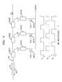
- FIG. 4is a schematic drawing depicting a number of pump wavelengths optically multiplexed together according to the present invention
- FIG. 5is a graph showing Raman gain (dB) vs. wavelength
- FIG. 6is a schematic drawing illustrating an alternative arrangement of the present invention.
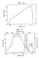
- FIG. 7is a graph showing the >8 THz wide flat gain band (from about 1530 to 1595 nm);
- FIG. 8is a graph showing an expanded view of the flat gain region of FIG. 7;
- FIG. 9is a graph showing a periodic variation in the pump frequencies suitable to yield the weighting function shown in FIG. 7;
- FIG. 10is a graph showing an exemplary swept frequency gain spectrum according to the present invention.
- FIG. 11is a graph showing Raman gain vs. Frequency for a reduced gain bandwidth according to the present invention.
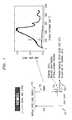
- the Raman effect in silica-glass fibersbegins with a pump-induced transition from a ground state 101 to a virtual state 102 , followed by an emission 103 from that virtual state 102 , where the emission terminates on an excited state 104 of the lattice. Emission of an optical phonon 105 (which typically takes place within a few femtoseconds) then completes return to the ground state 101 .
- optical transitionsare really highly non-resonant ones to the excited electronic levels, which in silica glass, lie some 5 - 6 eV above the ground state. Hence, the optical transitions get their strength primarily from the matrix elements of the very strong, allowed transition to the first electronic state.
- the Raman responseis essentially “instantaneous”, and hence tends to create a serious problem with dependence of the gain on signal pattern in forward pumping (pump and signal traveling in the same direction).
- the long effective path for interaction between pump and signal obtained with backward Raman pumpingtypically corresponds to effective integration times of several hundreds of microseconds. This is as long or longer than the integration times of erbium amplifiers operated at high pump and signal power levels, and is more than long enough to eliminate the problem of pattern dependence, even with the time-division multiplexing scheme presented here and in accordance with the present invention.
- the Raman effectis greatest when the pump and signal are co-polarized, and is nearly zero when they are orthogonally polarized (see insert to FIG. 1 .
- This polarization dependenceis overcome: first, by making the pump itself unpolarized, and second, by using only backward Raman pumping.
- ⁇ p and P pare the fiber loss coefficient and power, respectively, at the pump wavelength
- ⁇ s and P sare the corresponding quantities at the signal wavelength
- a effis the fiber effective core area
- the exact shape of the Raman gain banddepends somewhat on the glass composition, nevertheless, the examples shown in FIG. 1, for nearly pure silica glass, and in FIG. 2, for dispersion shifted fiber, are typical, the shape is always highly asymmetrical, with an almost linear slope to zero frequency difference, and with a much steeper descent on the high frequency side of the peak.
- the asymmetry of the Raman responsetends to dictate a rather odd, highly non-uniform distribution of relative powers of the various pump wavelengths. The required distribution, however, no matter how complicated, is particularly easy and economical to achieve with the technique to be described here.
- the pump wavelengthstravel down the fiber together, energy is rather quickly transferred from the shorter to the longer wavelength. Therefore, on a path-average basis, the distribution of relative powers between the two pumps is much different from the initial (and presumably intended) one. Furthermore, since it is important that the Raman gain be as uniformly distributed throughout the fiber span as the linear fiber loss will allow, “pre-emphasizing” the shorter wavelength power is not a satisfactory solution either.
- the two pump wavelengthscan travel down the fiber at separate times, and thus avoid interaction. As long as the rate at which the power is dithered back and forth between the wavelengths is fast enough relative to the effective integration time, the accumulated signal gain will remain time (and hence pattern) independent.
- the required frequency of ditheringneed be no greater than about one, or at the very most, a few MHz.
- the required electronic drive of the lasersis simple, cheap, and easily constructed.
- FIG. 4There are two basic versions of the time-division multiplexing scheme which is the subject of the present invention.
- a number of fixed-wavelength lasers 401 ( 1 ) . . . 401 (N)are optically multiplexed together, but made to operate at separate times through the use of appropriately pulsed drive currents effected by voltage controlled gates 402 ( 1 ) . . . 402 (N), respectively.
- this versionis of limited resolution for the attainment of flat gain (see FIG. 5 ), and the requirement for multiple lasers and multiplexers is awkward, expensive, and would tend to consume a lot of space.
- FIG. 5As is depicted in FIG.
- optical signals 410 traversing optical system 425includes combined counter propagating Raman pump signal 420 produced by combining the output pumps of lasers 401 ( 1 ) . . . 401 (N) which are coupled into the optical system 425 by couplers 426 ( 1 ) . . . 426 (N), respectively.
- optical signals 610 traversing optical system 625include counter propagating Raman pump signal 620 coupled into the optical system 625 by coupler 626 .
- Raman pump signal 620is advantageously generated by a single laser 601 ( 1 ) or, alternatively two 601 (N) the output of which are polarization multiplexed together by polarization combiner 630 .
- the pump laser(s)are effected with steady (d.c.) current drive, but whose wavelength is continuously and periodically scanned through the action and effect of programmable electronic function generator 650 .
- the programmable function produced by the programmable electronic function generatormay be varied in a desired manner to obtain the desired flat gain band.
- This version(which for convenience, we shall henceforth refer to as the “swept-wavelength” or “swept-frequency” scheme), has the two great advantages of simplicity (and hence economy) on the one hand, and of resolution limited only by the bandwidth of the wavelength-scanning drive electronics on the other. Since that bandwidth could easily be in the range of many tens, or even hundreds of MHz, while still accomplished with inexpensive electronics, the resolution could always be much better than with the first version. It should also be noted that the rapid frequency scanning would tend to obviate the need for other forms of frequency broadening of the laser to avoid Brillouin back scattering of the pump.
- both the extent and the shape of the Raman gain bandcan be easily and very quickly controlled through simple adjustment of the pertinent electronic waveforms.
- This simplicity, low cost and speed of gain shape adjustmentshould be compared with the high cost, complexity, lower speed, and optical insertion loss associated with purely optical gain equalizers.
- FIG. 7shows the >8 THz wide flat gain band (from about 1530 to 1595 nm), along with the required weighting function for the pump wavelengths, as they are swept between the limits of about 1515 to 1410 nm.
- this gain bandis essentially as wide as the combined “C” and “L” bands of the much more complex and cumbersome erbium fiber amplifiers. Note further that the band represents enough space for 3.2 Tbit/s of transmission capacity at a spectral efficiency of 0.4.
- FIG. 8is an expanded view of the flat gain region, and shows that the gain ripple can be held to less than 0.01 dB (again, out of a nominal 20 dB), or to less than 0.05% variation across the band.
- the gain rippleis still quite small ( ⁇ 0.02 dB) across the 8 THz band; this may be important for realization with a practical laser.
- FIG. 9shows the required periodic variation in the pump frequencies to yield the weighting function shown in FIG. 7 .
- the drive electronicsneed have a bandwidth no greater than about 100 times the fundamental drive frequency to reproduce the results of FIGS. 7 and 8 accurately.
- the electronic bandwidthneed be no more than about 100 MHz, a requirement that is very easily met.
- the shape of the gain bandis not restricted to the dead flat curve of FIG. 8 .
- the swept-frequency methodallows for other simple shapes as well, such as the linear slope shown in FIG. 10, which might be needed to compensate for the Raman interaction among the various channels in dense WDM. (The longer wavelength channels experience gain from interaction with the shorter wavelength channels.)
- just about any shape of gain bandis possible, as long as it can be represented by a smooth and not too rapidly varying function.
- FIG. 11shows an example of this reduction, to a 5 THz gain bandwidth which requires only a 10 THz frequency sweep of the pump lasers, and a laser power factor of only 1.56.
- the tuning of this deviceis based on the fact that a relatively small change in index of the semiconductor (produced by a control current) can easily vary the phase matching wavelength of a long period grating over a large range, viz., 80 nm or more.
- the long period gratingis used to couple the back facet of the laser to a broad-band mirror, so that significant feedback takes place only at the phase matching wavelength.
- Another possibilitymight be to use a piece of LiNbO 3 or other suitable electro-optic crystal to make a broadly tunable Lyot filter to be inserted into the feedback loop of the laser.
- the problemcould be relieved by combining the techniques of FIGS. 4 and 6.
- the pump weighting distributionstend to divide into two fairly well separated bands, viz., a narrower, higher density band covering the lower frequency range, and a broader, lower density band covering the higher pump frequencies.
- a pair of swept frequency laserseach designed specifically for one or the other of these two more restricted frequency ranges, and multiplexed together with a WDM coupler having a sharp transition in the region of the frequency gap, could alternate appropriately in time to provide the equivalent of the overall swept frequency distribution.
Landscapes
- Physics & Mathematics (AREA)
- Electromagnetism (AREA)
- Engineering & Computer Science (AREA)
- Computer Networks & Wireless Communication (AREA)
- Signal Processing (AREA)
- Lasers (AREA)
- Optical Modulation, Optical Deflection, Nonlinear Optics, Optical Demodulation, Optical Logic Elements (AREA)
- Optical Communication System (AREA)
Abstract
Description
This invention relates generally to the field of optical communications and in particular to a method and apparatus for producing a flat Raman gain over very long bands.
Early proposals for all-optical transmission (see, e.g., A. Hasegawa, “Numerical study of optical soliton transmission amplified periodically by the stimulated Raman process,” Appl. Opt., 23,1095 (1984); L. F. Mollenauer, J. P. Gordon, and M. N. Islam, “Soliton propagation in long fibers with periodically compensated loss,” IEEE J. Quantum Electronics QE-22, 157 (1986)) were based on the use of gain from the Raman effect to turn spans of transmission fiber into their own amplifiers. The scheme afforded many fundamental advantages, and indeed, it was used successfully for the first demonstration of an all-optical, long-distance transmission and subsequently reported by L. F. Mollenauer and K. Smith, in an article entitled “Demonstration of soliton transmission over more than 4000 km in fiber with loss periodically compensated by Raman gain,” which appeared in Opt. Lett. 13, 675 (1988).
Nevertheless, with the advent of the erbium fiber amplifier in the late 1980's, Raman amplification temporarily fell out of vogue, largely due to the pump powers required. That is, within the context of single-channel transmission, where the signal powers are rarely more than one or two milliwatts, the several hundreds of milliwatts threshold power required for net positive Raman gain seemed excessive and, at the time, impractical. With the recent ascendance of dense WDM (where net signal levels can easily reach one hundred mW or more), and with the simultaneous commercial availability of several-hundred mW output semiconductor pump lasers, however, opinion has changed. Now Raman gain is highly prized for its ability to overcome noise/non-linear penalties, and for the fact that the position and extent of the gain band depend only on the available pump wavelengths. Another extremely important advantage of Raman amplification for dense WDM lies in the fact that, in stark contrast to erbium amplifiers, the shape of the Raman gain band is essentially independent of pump and signal levels.
As a result of its importance to optical transmission systems, methods and apparatus which facilitate the production and utilization of Raman gain are desired and a continuous avenue for exploration.
We have developed a method and apparatus for producing a flat gain over very broad gain bands utilizing backward-pumped Raman amplification. The method allows for dynamic gain control through simple electronic means.
The method involves the time division multiplexing of combined pump wavelengths to attain broad Raman gain bands. Originally conceived as a way to prevent the various pump wavelengths from interacting with each other, our method has proven to have several other very great and important advantages, especially in a preferred, frequency-swept embodiment.
Specifically, our frequency-swept method produces extremely flat gain (variation less than 0.05%) across gain bands at least 8 THz wide while allowing for a wide variation of adjustment in the shape of the gain band, as might be required to overcome various system defects. Advantageously, all of these conditions may be established and altered within microseconds, utilizing known, simple, all-electronic control.
FIG. 1 is a schematic drawing illustrating the Raman effect and a graph depicting the Raman gain;
FIG. 2 is a graph showing the Raman gain for dispersion shifted optical fiber;
FIG. 3 is a graph showing pump wavelength vs. distance for a Raman pump;
FIG. 4 is a schematic drawing depicting a number of pump wavelengths optically multiplexed together according to the present invention;
FIG. 5 is a graph showing Raman gain (dB) vs. wavelength;
FIG. 6 is a schematic drawing illustrating an alternative arrangement of the present invention;
FIG. 7 is a graph showing the >8 THz wide flat gain band (from about 1530 to 1595 nm);
FIG. 8 is a graph showing an expanded view of the flat gain region of FIG. 7;
FIG. 9 is a graph showing a periodic variation in the pump frequencies suitable to yield the weighting function shown in FIG. 7;
FIG. 10 is a graph showing an exemplary swept frequency gain spectrum according to the present invention; and
FIG. 11 is a graph showing Raman gain vs. Frequency for a reduced gain bandwidth according to the present invention.
By way of background and with reference to FIG. 1, there is shown in schematic form a diagram depicting the Raman effect. Briefly, and with reference to that Fig, the Raman effect in silica-glass fibers begins with a pump-induced transition from aground state 101 to avirtual state 102, followed by anemission 103 from thatvirtual state 102, where the emission terminates on anexcited state 104 of the lattice. Emission of an optical phonon105 (which typically takes place within a few femtoseconds) then completes return to theground state 101.
The optical transitions are really highly non-resonant ones to the excited electronic levels, which in silica glass, lie some5-6 eV above the ground state. Hence, the optical transitions get their strength primarily from the matrix elements of the very strong, allowed transition to the first electronic state.
Because of the extremely fast relaxation, the population of the terminal state of the optical emission tends to be determined by equilibrium with the surrounding phonon bath, and hence is almost independent of the rates of optical pumping and emission. This fact is the source of the independence, cited above, of the shape of the Raman gain band from the optical pumping dynamics.
It is important to note that the Raman response, as just described, is essentially “instantaneous”, and hence tends to create a serious problem with dependence of the gain on signal pattern in forward pumping (pump and signal traveling in the same direction). Nevertheless, the long effective path for interaction between pump and signal obtained with backward Raman pumping (approximately equal to twice the characteristic fiber loss length), typically corresponds to effective integration times of several hundreds of microseconds. This is as long or longer than the integration times of erbium amplifiers operated at high pump and signal power levels, and is more than long enough to eliminate the problem of pattern dependence, even with the time-division multiplexing scheme presented here and in accordance with the present invention.
The Raman effect is greatest when the pump and signal are co-polarized, and is nearly zero when they are orthogonally polarized (see insert to FIG.1. There are essentially two ways in which this polarization dependence is overcome: first, by making the pump itself unpolarized, and second, by using only backward Raman pumping.
In the latter, in response to the usual fiber birefringence, the Stokes vectors representing the (opposite-traveling) pump and signal rotate around the Poincare sphere in opposite directions, thus thoroughly averaging the relative polarization states of pump and signal on a path-average basis. Either method tends to be fairly effective all by itself, but when used together, any measurable polarization dependence of the Raman gain tends to disappear altogether.
The pump and signal photons interact with each other according to the following pair of coupled equations:

where αpand Ppare the fiber loss coefficient and power, respectively, at the pump wavelength, and αsand Psare the corresponding quantities at the signal wavelength, Aeffis the fiber effective core area, and R the Raman gain factor. At the peak of the Raman gain band, for copolarized pump and signal in pure silica fiber, R=68 km−1/W/(μm)2, while for an unpolarized pump, it has roughly half that value. Finally, R increases significantly with increasing Ge content of the fiber.
Although the exact shape of the Raman gain band depends somewhat on the glass composition, nevertheless, the examples shown in FIG. 1, for nearly pure silica glass, and in FIG. 2, for dispersion shifted fiber, are typical, the shape is always highly asymmetrical, with an almost linear slope to zero frequency difference, and with a much steeper descent on the high frequency side of the peak. In the use of multiplexed pump frequencies (or wavelengths) to achieve a broader flat gain band, as we shall illustrate soon, the asymmetry of the Raman response tends to dictate a rather odd, highly non-uniform distribution of relative powers of the various pump wavelengths. The required distribution, however, no matter how complicated, is particularly easy and economical to achieve with the technique to be described here.
We originally conceived an aspect of the present invention as a way to overcome a fundamental problem that otherwise tends to accompany the use of multiple pump wavelengths, viz., the very strong and harmful interaction that can obtain among them via the Raman effect itself. Consider, for the simplest example, the interaction between just two pump wavelengths, which interaction can be computed from the coupled Eqns(1) by treating the longer of the two pump wavelengths as the signal.
As illustrated in FIG.3 and with reference now to that FIG., as the pump wavelengths travel down the fiber together, energy is rather quickly transferred from the shorter to the longer wavelength. Therefore, on a path-average basis, the distribution of relative powers between the two pumps is much different from the initial (and presumably intended) one. Furthermore, since it is important that the Raman gain be as uniformly distributed throughout the fiber span as the linear fiber loss will allow, “pre-emphasizing” the shorter wavelength power is not a satisfactory solution either. We note, however, the two pump wavelengths can travel down the fiber at separate times, and thus avoid interaction. As long as the rate at which the power is dithered back and forth between the wavelengths is fast enough relative to the effective integration time, the accumulated signal gain will remain time (and hence pattern) independent. Since, as already noted, the integration time with backward Raman pumping tends to be of order several hundreds of microseconds, the required frequency of dithering need be no greater than about one, or at the very most, a few MHz. For that frequency range, the required electronic drive of the lasers is simple, cheap, and easily constructed.
There are two basic versions of the time-division multiplexing scheme which is the subject of the present invention. In the first, shown schematically in FIG. 4, a number of fixed-wavelength lasers401(1) . . .401(N) are optically multiplexed together, but made to operate at separate times through the use of appropriately pulsed drive currents effected by voltage controlled gates402(1) . . .402(N), respectively. Although conceptually simple, this version is of limited resolution for the attainment of flat gain (see FIG.5), and the requirement for multiple lasers and multiplexers is awkward, expensive, and would tend to consume a lot of space. As is depicted in FIG. 4,optical signals 410 traversingoptical system 425 includes combined counter propagatingRaman pump signal 420 produced by combining the output pumps of lasers401(1) . . .401(N) which are coupled into theoptical system 425 by couplers426(1) . . .426(N), respectively.
With reference now to FIG. 6, there is shown an alternative embodiment of the present invention. Specifically,optical signals 610 traversingoptical system 625 include counter propagatingRaman pump signal 620 coupled into theoptical system 625 bycoupler 626.Raman pump signal 620 is advantageously generated by a single laser601(1) or, alternatively two601(N) the output of which are polarization multiplexed together bypolarization combiner 630. Furthermore, and in accordance with an aspect of the present invention, the pump laser(s) are effected with steady (d.c.) current drive, but whose wavelength is continuously and periodically scanned through the action and effect of programmableelectronic function generator 650. Advantageously, the programmable function produced by the programmable electronic function generator may be varied in a desired manner to obtain the desired flat gain band. This version (which for convenience, we shall henceforth refer to as the “swept-wavelength” or “swept-frequency” scheme), has the two great advantages of simplicity (and hence economy) on the one hand, and of resolution limited only by the bandwidth of the wavelength-scanning drive electronics on the other. Since that bandwidth could easily be in the range of many tens, or even hundreds of MHz, while still accomplished with inexpensive electronics, the resolution could always be much better than with the first version. It should also be noted that the rapid frequency scanning would tend to obviate the need for other forms of frequency broadening of the laser to avoid Brillouin back scattering of the pump.
Finally, it should be noted that for either scheme, both the extent and the shape of the Raman gain band can be easily and very quickly controlled through simple adjustment of the pertinent electronic waveforms. This simplicity, low cost and speed of gain shape adjustment should be compared with the high cost, complexity, lower speed, and optical insertion loss associated with purely optical gain equalizers.
For our swept-frequency method, we have developed an efficient algorithm to determine that weighting function for a given band of Raman pump frequencies that will yield the flattest and widest possible gain band. The algorithm uses the experimentally measured gain spectrum for a single pump frequency (such as that shown in FIG.2). It begins with assumption of the desired flat portion of the desired gain spectrum and an educated guess as to the corresponding skirts; the corresponding weighting function is then found by Fourier transformation of the defining equation. This solution is then improved through iteration, where the calculated pump weighting is used to predict better values for the Raman gain spectrum. Although as many as 50 to 100 iterations are often required, the entire process usually takes less than one minute on a fast PC.
With simultaneous reference now to FIGS. 7 and 8, there is shown but one example of the sort of results that can be obtained using that algorithm. More specifically, FIG. 7 shows the >8 THz wide flat gain band (from about 1530 to 1595 nm), along with the required weighting function for the pump wavelengths, as they are swept between the limits of about 1515 to 1410 nm. (Note that this gain band is essentially as wide as the combined “C” and “L” bands of the much more complex and cumbersome erbium fiber amplifiers. Note further that the band represents enough space for 3.2 Tbit/s of transmission capacity at a spectral efficiency of 0.4.)
FIG. 8 is an expanded view of the flat gain region, and shows that the gain ripple can be held to less than 0.01 dB (again, out of a nominal 20 dB), or to less than 0.05% variation across the band. We have also determined that reduction in the pump sweep from the 105 nm (15 THz) range cited above to 84 nm (12 THz), the gain ripple is still quite small (<0.02 dB) across the 8 THz band; this may be important for realization with a practical laser.
FIG. 9 shows the required periodic variation in the pump frequencies to yield the weighting function shown in FIG.7. Under the assumption that the pump laser's output frequency will be more or less linearly related to the voltage or current used to tune it, the drive electronics need have a bandwidth no greater than about 100 times the fundamental drive frequency to reproduce the results of FIGS. 7 and 8 accurately. Thus, in this example, where the assumed fundamental drive frequency is 1 MHz, the electronic bandwidth need be no more than about 100 MHz, a requirement that is very easily met.
It should also be understood that the shape of the gain band is not restricted to the dead flat curve of FIG.8. The swept-frequency method allows for other simple shapes as well, such as the linear slope shown in FIG. 10, which might be needed to compensate for the Raman interaction among the various channels in dense WDM. (The longer wavelength channels experience gain from interaction with the shorter wavelength channels.) In principle, just about any shape of gain band is possible, as long as it can be represented by a smooth and not too rapidly varying function.
Use of the swept-frequency technique significantly increases the required laser power over that required for narrow-band gain with a fixed frequency pump. In the case of FIG. 7, for example, that factor is 1.87. To give a feeling for the absolute pump powers required, consider an 80 km span of dispersion shifted fiber (with effective core area of about 50 μm2, where about 75%, or 12.5 dB of its 16.8 dB span loss is to be compensated by backward-pumped Raman gain. (To compensate more than that fraction can cause problems from Rayleigh double-back scattering of the signals themselves.) In that case, and with negligible levels of signal power, 285 mW of pump power is required for the narrow-band gain, but to produce the 8 THz flat gain band cited here, that power rises to 533 mW. When significant signal powers are involved (as is the case in dense WDM), the pump power must be increased further by an amount somewhat greater than the total signal power itself
We also note that for some applications, where the full 8 THz bandwidth of the previous example may not be required, a reduced gain bandwidth allows for a corresponding reduction in the required frequency sweep and power output of the pump laser. FIG. 11 shows an example of this reduction, to a 5 THz gain bandwidth which requires only a 10 THz frequency sweep of the pump lasers, and a laser power factor of only 1.56.
Perhaps the best way to meet the combined requirements for high output power (typically 0.5 W or greater coupled into fiber) and for fast, wide (80 nm or more) frequency tuning of the pump laser, is to use the combination of a widely tunable, lower-power (semiconductor) laser of proven design, followed by a (semiconductor) traveling wave amplifier. An excellent candidate for the tunable laser is the “tunable vertical-coupler filtered laser” or VCFL, as described by I. Kim et al., in an article entitled “Broadly tunable vertical-coupler filtered tensile-strained InFaAs/InGaAsP multiple quantum well laser,” which appeared in Appl. Phys. Lett., Vol 64, pp. 2764 (1994). The tuning of this device is based on the fact that a relatively small change in index of the semiconductor (produced by a control current) can easily vary the phase matching wavelength of a long period grating over a large range, viz., 80 nm or more. The long period grating is used to couple the back facet of the laser to a broad-band mirror, so that significant feedback takes place only at the phase matching wavelength. Another possibility might be to use a piece of LiNbO3or other suitable electro-optic crystal to make a broadly tunable Lyot filter to be inserted into the feedback loop of the laser.
Various additional modifications of this invention will occur to those skilled in the art. Nevertheless, all deviations from the specific teachings of this specification that basically rely upon the principles and their equivalents through which the art has been advanced are properly considered within the scope of the invention as described and claimed.
For example, should it prove difficult to realize a pump laser which can maintain high power output while its frequency is swept over a very wide band (say, 80 nm or more), the problem could be relieved by combining the techniques of FIGS. 4 and 6. In particular, notice from FIGS. 7 and 11 that the pump weighting distributions tend to divide into two fairly well separated bands, viz., a narrower, higher density band covering the lower frequency range, and a broader, lower density band covering the higher pump frequencies. Thus, a pair of swept frequency lasers, each designed specifically for one or the other of these two more restricted frequency ranges, and multiplexed together with a WDM coupler having a sharp transition in the region of the frequency gap, could alternate appropriately in time to provide the equivalent of the overall swept frequency distribution.
Claims (29)
1. A method of pumping an optical system including a plurality of Raman pumps CHARACTERIZED BY
time-division multiplexing of Raman pump wavelengths into the optical system.
2. The method according toclaim 1 wherein said Raman pump wavelengths comprise a finite set of discrete wavelengths.
3. The method according toclaim 1 wherein the plurality of Raman pumps produce pump signals of varying wavelengths.
4. The method according toclaim 1 wherein said Raman pump wavelengths traverse the optical system in a same direction as an optical signal traversing the optical system.
5. The method according toclaim 1 wherein said Raman pump wavelengths traverse the optical system in a counter-propagating direction an optical signal traversing the optical system.
6. The method according toclaim 1 wherein selected Raman pump wavelengths comprise a finite set of discrete wavelengths and other selected pump wavelengths are varying.
7. In an optical system comprising:
an optical path;
a plurality of couplers in optical communication with the path;
a plurality of Raman pumps, optically connected to the optical couplers;
a method of pumping the optical system CHARACTERIZED IN THAT: Raman pump wavelengths output by the Raman pumps are time division multiplexed into the optical system.
8. The method according toclaim 7 wherein said Raman pump wavelengths comprise a finite set of discrete wavelengths.
9. The method according toclaim 7 wherein said Raman pump wavelengths are varying.
10. The method according toclaim 7 wherein the Raman pump wavelengths are coupled into the optical system such that they traverse the optical system in a same direction as optical signals traversing the optical path.
11. The method according toclaim 7 wherein the Raman pump wavelengths are coupled into the optical system such that they traverse the optical system in a counter-propagating direction as optical signals traversing the optical path.
12. The method according toclaim 7 wherein selected ones of Raman pump wavelengths comprise a finite set of discrete wavelengths and other selected pump wavelengths are varying.
13. An optical system comprising:
an optical path;
means for generating a plurality optical Raman pump signals;
means for coupling the plurality of optical Raman pump signals into the optical path;
CHARACTERIZED IN THAT:
the plurality of optical Raman pump signals are time-division multiplexed.
14. The system ofclaim 13 wherein the optical Raman pump signals comprise a finite set of discrete wavelengths.
15. The system ofclaim 13 wherein the optical Raman pump signals comprise a set of varying wavelengths.
16. The system ofclaim 13 wherein the optical Raman pump signals are coupled into the optical path in a direction that is the same as an optical signal traversing the optical path.
17. The system ofclaim 13 wherein the optical Raman pump signals are coupled into the optical path in a direction that is counter to an optical signal traversing the optical path.
18. The system ofclaim 13 wherein selected ones of the Raman pump wavelengths comprise a finite set of discrete wavelengths and other selected pump wavelengths are varying.
19. A method of pumping an optical system from a plurality of Raman pumps such that Raman pump signals generated from the Raman pumps are time division multiplexed.
20. The method according toclaim 19 wherein the Raman pump signals are counter-propagating signals.
21. A method of generating a Raman gain band in an optical system having a plurality of optical Raman pumps, the method CHARACTERIZED BY:
time division multiplexing optical Raman signals produced by the Raman pumps into the optical system.
22. The method according toclaim 21 wherein the Raman pump signals are counter-propagating signals.
23. The method according toclaim 22 wherein the Raman pump signals are wavelength varying signals produced by a plurality of lasers and the wavelength varying characteristic is combined with synchronized control of the laser's output power.
24. A method of pumping an optical system including at least one Raman pump CHARACTERIZED BY
time-division multiplexing of the wavelengths of said at least one Raman pump into the optical system.
25. The method according toclaim 24 wherein the wavelengths of said at least one Raman pump comprise a finite set of discrete wavelengths.
26. The method according toclaim 24 wherein said at least one Raman pump produces pump signals of varying wavelengths.
27. The method according toclaim 24 wherein the wavelengths of said at least one Raman pump traverse the optical system in a counter-propagating direction as an optical signal traversing the optical system.
28. The method according toclaim 24 wherein the wavelengths of said at least one Raman pump traverse the optical system in a same direction as an optical signal traversing the optical system.
29. The method according toclaim 24 wherein the wavelengths of said at least one Raman pump have a continuous pump laser sweep pattern.
Priority Applications (5)
| Application Number | Priority Date | Filing Date | Title |
|---|---|---|---|
| US09/552,772US6611368B1 (en) | 2000-04-20 | 2000-04-20 | Time-division multiplexed pump wavelengths resulting in ultra broad band, flat, backward pumped Raman gain |
| CA002339756ACA2339756C (en) | 2000-04-20 | 2001-03-02 | Time-division multiplexed pump wavelengths resulting in ultra broad band, flat, backward pumped raman gain |
| DE60131800TDE60131800T2 (en) | 2000-04-20 | 2001-04-09 | Time-multiplexed pump wavelengths and resulting ultrabroadband uniform back-pumped Raman amplification |
| EP01303340AEP1148666B1 (en) | 2000-04-20 | 2001-04-09 | Time-division multiplexed pump wavelengths resulting in ultra broad band, flat, backward pumped raman gain |
| JP2001111420AJP2002006349A (en) | 2000-04-20 | 2001-04-10 | Method for pumping optical system having plural raman pumps |
Applications Claiming Priority (1)
| Application Number | Priority Date | Filing Date | Title |
|---|---|---|---|
| US09/552,772US6611368B1 (en) | 2000-04-20 | 2000-04-20 | Time-division multiplexed pump wavelengths resulting in ultra broad band, flat, backward pumped Raman gain |
Publications (1)
| Publication Number | Publication Date |
|---|---|
| US6611368B1true US6611368B1 (en) | 2003-08-26 |
Family
ID=24206741
Family Applications (1)
| Application Number | Title | Priority Date | Filing Date |
|---|---|---|---|
| US09/552,772Expired - LifetimeUS6611368B1 (en) | 2000-04-20 | 2000-04-20 | Time-division multiplexed pump wavelengths resulting in ultra broad band, flat, backward pumped Raman gain |
Country Status (5)
| Country | Link |
|---|---|
| US (1) | US6611368B1 (en) |
| EP (1) | EP1148666B1 (en) |
| JP (1) | JP2002006349A (en) |
| CA (1) | CA2339756C (en) |
| DE (1) | DE60131800T2 (en) |
Cited By (21)
| Publication number | Priority date | Publication date | Assignee | Title |
|---|---|---|---|---|
| US20030184849A1 (en)* | 2002-04-02 | 2003-10-02 | Alcatel | Method of distributed Raman amplification in an optical fiber |
| US20030210913A1 (en)* | 2002-03-01 | 2003-11-13 | Motoki Kakui | Light generator, optical amplifier, and optical communication system |
| US20040036956A1 (en)* | 2002-07-01 | 2004-02-26 | Jds Uniphase Corporation | Wider dynamic range to a FBG stabilized pump |
| US20040042061A1 (en)* | 2002-08-30 | 2004-03-04 | Islam Mohammed N. | Controlling ASE in optical amplification stages implementing time modulated pump signals |
| US20040071534A1 (en)* | 2002-07-18 | 2004-04-15 | August Technology Corp. | Adjustable wafer alignment arm |
| US6748136B2 (en)* | 2002-03-15 | 2004-06-08 | Fitel Usa Corp. | Wide band Raman amplifiers |
| US20040201881A1 (en)* | 2003-04-14 | 2004-10-14 | Alcatel | Raman amplifying device and method for pump modulation |
| US6813067B1 (en)* | 2002-11-05 | 2004-11-02 | At&T Corp. | Method and apparatus for providing a broadband raman amplifier with improved noise performance |
| US20050063043A1 (en)* | 2002-11-18 | 2005-03-24 | Hiroshi Nakamoto | Raman amplifier |
| US20060050365A1 (en)* | 2002-10-04 | 2006-03-09 | Rainer Hainberger | Raman amplification system utilizing modulated second-order raman pumping |
| US20060061855A1 (en)* | 2004-09-17 | 2006-03-23 | Fujitsu Limited | Optical node |
| US7038839B1 (en)* | 2003-01-24 | 2006-05-02 | Sprint Communications Company L.P. | Optical signal amplification using multiple backward-pumping systems |
| US7180654B2 (en) | 2002-07-25 | 2007-02-20 | Fujitsu Limited | Raman amplifier |
| US7233742B2 (en)* | 2000-08-25 | 2007-06-19 | Fujitsu Limited | Optical communication system, method for supplying pump light, and distributed Raman amplifying apparatus |
| US20090174932A1 (en)* | 2008-01-07 | 2009-07-09 | Xtera Communications, Inc. | Optical amplifier bandwidth alteration |
| US20090185262A1 (en)* | 2008-01-22 | 2009-07-23 | Xiaodong Duan | Optical Amplifier With Time-Multiplexed Pump Laser |
| US20110176201A1 (en)* | 2008-10-06 | 2011-07-21 | Cesnet, Zajmove Sdruzeni Pravnickych Osob | Modular set of devices for optical amplification of signal by raman fiber amplifier |
| WO2012085561A1 (en) | 2010-12-22 | 2012-06-28 | Oclaro Technology Limited | Raman amplifiers |
| CN106785841A (en)* | 2016-12-26 | 2017-05-31 | 华南理工大学 | A kind of optical fiber Raman amplifier of FPGA time-sharing multiplexs pumping schemes |
| US9762319B1 (en)* | 2015-09-29 | 2017-09-12 | Juniper Networks, Inc. | Real-time Raman gain monitoring |
| US10527587B2 (en)* | 2017-12-05 | 2020-01-07 | Hohai University | Distributed sensing fiber acoustic emission apparatus and method for monitoring hydraulic engineering safety behavior |
Families Citing this family (15)
| Publication number | Priority date | Publication date | Assignee | Title |
|---|---|---|---|---|
| US6611368B1 (en)* | 2000-04-20 | 2003-08-26 | Lucent Technologies Inc. | Time-division multiplexed pump wavelengths resulting in ultra broad band, flat, backward pumped Raman gain |
| US20030081307A1 (en)* | 2001-09-28 | 2003-05-01 | Fludger Christopher R. | Raman amplification |
| DE10153744B4 (en)* | 2001-10-31 | 2008-02-28 | Nokia Siemens Networks Gmbh & Co.Kg | Pump source with multiple pump lasers for Raman amplification of a WDM signal with minimized four-wave mixing |
| US7259906B1 (en) | 2002-09-03 | 2007-08-21 | Cheetah Omni, Llc | System and method for voice control of medical devices |
| JP4062062B2 (en)* | 2002-11-15 | 2008-03-19 | 住友電気工業株式会社 | Excitation module for Raman amplification |
| KR100533914B1 (en) | 2003-10-08 | 2005-12-06 | 한국전자통신연구원 | Raman amplifier and Raman pumping method |
| US7519253B2 (en) | 2005-11-18 | 2009-04-14 | Omni Sciences, Inc. | Broadband or mid-infrared fiber light sources |
| WO2011084863A2 (en) | 2010-01-07 | 2011-07-14 | Cheetah Omni, Llc | Fiber lasers and mid-infrared light sources in methods and systems for selective biological tissue processing and spectroscopy |
| WO2014143276A2 (en) | 2012-12-31 | 2014-09-18 | Omni Medsci, Inc. | Short-wave infrared super-continuum lasers for natural gas leak detection, exploration, and other active remote sensing applications |
| EP2938259A4 (en) | 2012-12-31 | 2016-08-17 | Omni Medsci Inc | Near-infrared lasers for non-invasive monitoring of glucose, ketones, hba1c, and other blood constituents |
| CA2895982A1 (en) | 2012-12-31 | 2014-07-03 | Omni Medsci, Inc. | Short-wave infrared super-continuum lasers for early detection of dental caries |
| US10660526B2 (en) | 2012-12-31 | 2020-05-26 | Omni Medsci, Inc. | Near-infrared time-of-flight imaging using laser diodes with Bragg reflectors |
| US9500634B2 (en) | 2012-12-31 | 2016-11-22 | Omni Medsci, Inc. | Short-wave infrared super-continuum lasers for natural gas leak detection, exploration, and other active remote sensing applications |
| US9993159B2 (en) | 2012-12-31 | 2018-06-12 | Omni Medsci, Inc. | Near-infrared super-continuum lasers for early detection of breast and other cancers |
| US12193790B2 (en) | 2012-12-31 | 2025-01-14 | Omni Medsci, Inc. | Wearable devices comprising semiconductor diode light sources with improved signal-to-noise ratio |
Citations (15)
| Publication number | Priority date | Publication date | Assignee | Title |
|---|---|---|---|---|
| USH499H (en)* | 1986-09-02 | 1988-07-05 | The United States Of America As Represented By The United States Department Of Energy | System and method for linearly amplifying optical analog signals by backward Raman scattering |
| EP0286338A1 (en)* | 1987-04-06 | 1988-10-12 | BRITISH TELECOMMUNICATIONS public limited company | Radiation pulse generation |
| DE19516262A1 (en) | 1995-04-27 | 1996-10-31 | Hertz Inst Heinrich | Photonic time cell selector apparatus for digital optical time multiplex signal |
| JPH0961861A (en)* | 1995-08-28 | 1997-03-07 | Res Dev Corp Of Japan | Optical soliton control system |
| EP0843435A2 (en) | 1996-11-13 | 1998-05-20 | AT&T Corp. | Time division demultiplexing using selective raman amplification |
| US5883736A (en) | 1996-02-23 | 1999-03-16 | The Furukawa Electric Co., Ltd. | Er-doped optical fiber amplifier |
| WO2000005622A1 (en) | 1998-07-23 | 2000-02-03 | The Furukawa Electric Co., Ltd. | Raman amplifier, optical repeater, and raman amplification method |
| US6191877B1 (en)* | 1995-02-17 | 2001-02-20 | Lucent Technologies Inc. | WDM optical fiber system using Raman amplification |
| US6262823B1 (en)* | 1998-05-11 | 2001-07-17 | Compaq Computer Corp. | System for optical time domain multiplexing of digital signals |
| EP1148666A2 (en)* | 2000-04-20 | 2001-10-24 | Lucent Technologies Inc. | Time-division multiplexed pump wavelengths resulting in ultra broad band, flat, backward pumped raman gain |
| US6388781B1 (en)* | 1998-11-25 | 2002-05-14 | Nortel Networks Limited | Apparatus for time division/wave division conversion |
| US6417959B1 (en)* | 2000-12-04 | 2002-07-09 | Onetta, Inc. | Raman fiber amplifier |
| US6452716B1 (en)* | 2000-10-05 | 2002-09-17 | Nortel Networks Limited | Amplitude modulation of a pump laser signal in a distributed raman amplifier |
| US6480326B2 (en)* | 2000-07-10 | 2002-11-12 | Mpb Technologies Inc. | Cascaded pumping system and method for producing distributed Raman amplification in optical fiber telecommunication systems |
| US6504645B1 (en)* | 2000-08-29 | 2003-01-07 | Lucent Technologies Inc. | Chalcogenide glass based Raman optical amplifier |
Family Cites Families (2)
| Publication number | Priority date | Publication date | Assignee | Title |
|---|---|---|---|---|
| JPH02272432A (en)* | 1989-04-13 | 1990-11-07 | Nippon Telegr & Teleph Corp <Ntt> | Polarized wave modulating device |
| JP4115027B2 (en)* | 1998-07-23 | 2008-07-09 | 古河電気工業株式会社 | Excitation light generation means, Raman amplifier and optical repeater using the same |
- 2000
- 2000-04-20USUS09/552,772patent/US6611368B1/ennot_activeExpired - Lifetime
- 2001
- 2001-03-02CACA002339756Apatent/CA2339756C/ennot_activeExpired - Fee Related
- 2001-04-09EPEP01303340Apatent/EP1148666B1/ennot_activeExpired - Lifetime
- 2001-04-09DEDE60131800Tpatent/DE60131800T2/ennot_activeExpired - Lifetime
- 2001-04-10JPJP2001111420Apatent/JP2002006349A/enactivePending
Patent Citations (16)
| Publication number | Priority date | Publication date | Assignee | Title |
|---|---|---|---|---|
| USH499H (en)* | 1986-09-02 | 1988-07-05 | The United States Of America As Represented By The United States Department Of Energy | System and method for linearly amplifying optical analog signals by backward Raman scattering |
| EP0286338A1 (en)* | 1987-04-06 | 1988-10-12 | BRITISH TELECOMMUNICATIONS public limited company | Radiation pulse generation |
| US6191877B1 (en)* | 1995-02-17 | 2001-02-20 | Lucent Technologies Inc. | WDM optical fiber system using Raman amplification |
| DE19516262A1 (en) | 1995-04-27 | 1996-10-31 | Hertz Inst Heinrich | Photonic time cell selector apparatus for digital optical time multiplex signal |
| JPH0961861A (en)* | 1995-08-28 | 1997-03-07 | Res Dev Corp Of Japan | Optical soliton control system |
| US5883736A (en) | 1996-02-23 | 1999-03-16 | The Furukawa Electric Co., Ltd. | Er-doped optical fiber amplifier |
| EP0843435A2 (en) | 1996-11-13 | 1998-05-20 | AT&T Corp. | Time division demultiplexing using selective raman amplification |
| US6262823B1 (en)* | 1998-05-11 | 2001-07-17 | Compaq Computer Corp. | System for optical time domain multiplexing of digital signals |
| WO2000005622A1 (en) | 1998-07-23 | 2000-02-03 | The Furukawa Electric Co., Ltd. | Raman amplifier, optical repeater, and raman amplification method |
| US6388781B1 (en)* | 1998-11-25 | 2002-05-14 | Nortel Networks Limited | Apparatus for time division/wave division conversion |
| EP1148666A2 (en)* | 2000-04-20 | 2001-10-24 | Lucent Technologies Inc. | Time-division multiplexed pump wavelengths resulting in ultra broad band, flat, backward pumped raman gain |
| JP2002006349A (en)* | 2000-04-20 | 2002-01-09 | Lucent Technol Inc | Method for pumping optical system having plural raman pumps |
| US6480326B2 (en)* | 2000-07-10 | 2002-11-12 | Mpb Technologies Inc. | Cascaded pumping system and method for producing distributed Raman amplification in optical fiber telecommunication systems |
| US6504645B1 (en)* | 2000-08-29 | 2003-01-07 | Lucent Technologies Inc. | Chalcogenide glass based Raman optical amplifier |
| US6452716B1 (en)* | 2000-10-05 | 2002-09-17 | Nortel Networks Limited | Amplitude modulation of a pump laser signal in a distributed raman amplifier |
| US6417959B1 (en)* | 2000-12-04 | 2002-07-09 | Onetta, Inc. | Raman fiber amplifier |
Non-Patent Citations (6)
Cited By (32)
| Publication number | Priority date | Publication date | Assignee | Title |
|---|---|---|---|---|
| US7233742B2 (en)* | 2000-08-25 | 2007-06-19 | Fujitsu Limited | Optical communication system, method for supplying pump light, and distributed Raman amplifying apparatus |
| US20030210913A1 (en)* | 2002-03-01 | 2003-11-13 | Motoki Kakui | Light generator, optical amplifier, and optical communication system |
| US7580183B2 (en)* | 2002-03-01 | 2009-08-25 | Sumitomo Electric Industries, Ltd. | Light generator, optical amplifier, and optical communication system |
| US6748136B2 (en)* | 2002-03-15 | 2004-06-08 | Fitel Usa Corp. | Wide band Raman amplifiers |
| US20030184849A1 (en)* | 2002-04-02 | 2003-10-02 | Alcatel | Method of distributed Raman amplification in an optical fiber |
| US7016104B2 (en)* | 2002-07-01 | 2006-03-21 | Jds Uniphase Corporation | Wider dynamic range to a FBG stabilized pump |
| US20040036956A1 (en)* | 2002-07-01 | 2004-02-26 | Jds Uniphase Corporation | Wider dynamic range to a FBG stabilized pump |
| US20040071534A1 (en)* | 2002-07-18 | 2004-04-15 | August Technology Corp. | Adjustable wafer alignment arm |
| US7180654B2 (en) | 2002-07-25 | 2007-02-20 | Fujitsu Limited | Raman amplifier |
| US20040042061A1 (en)* | 2002-08-30 | 2004-03-04 | Islam Mohammed N. | Controlling ASE in optical amplification stages implementing time modulated pump signals |
| US20060050365A1 (en)* | 2002-10-04 | 2006-03-09 | Rainer Hainberger | Raman amplification system utilizing modulated second-order raman pumping |
| US7477446B2 (en) | 2002-10-04 | 2009-01-13 | Fujitsu Limited | Raman amplification system utilizing modulated second-order raman pumping |
| US6813067B1 (en)* | 2002-11-05 | 2004-11-02 | At&T Corp. | Method and apparatus for providing a broadband raman amplifier with improved noise performance |
| US7046427B1 (en)* | 2002-11-05 | 2006-05-16 | At&T Corp. | Method and apparatus for providing a broadband raman amplifier with improved noise performance |
| US20050063043A1 (en)* | 2002-11-18 | 2005-03-24 | Hiroshi Nakamoto | Raman amplifier |
| US7379233B2 (en)* | 2002-11-18 | 2008-05-27 | Fujitsu Limited | Raman amplifier utilizing pump modulation for expanding gain band width |
| US7038839B1 (en)* | 2003-01-24 | 2006-05-02 | Sprint Communications Company L.P. | Optical signal amplification using multiple backward-pumping systems |
| US7116470B2 (en)* | 2003-04-14 | 2006-10-03 | Alcatel | Raman amplifying device and method for pump modulation |
| US20040201881A1 (en)* | 2003-04-14 | 2004-10-14 | Alcatel | Raman amplifying device and method for pump modulation |
| US7212333B2 (en)* | 2004-09-17 | 2007-05-01 | Fujitsu Limited | Optical node |
| US20060061855A1 (en)* | 2004-09-17 | 2006-03-23 | Fujitsu Limited | Optical node |
| US20090174932A1 (en)* | 2008-01-07 | 2009-07-09 | Xtera Communications, Inc. | Optical amplifier bandwidth alteration |
| US8233216B2 (en)* | 2008-01-07 | 2012-07-31 | Xtera Communications, Inc. | Optical amplifier bandwidth alteration |
| US20090185262A1 (en)* | 2008-01-22 | 2009-07-23 | Xiaodong Duan | Optical Amplifier With Time-Multiplexed Pump Laser |
| US20110176201A1 (en)* | 2008-10-06 | 2011-07-21 | Cesnet, Zajmove Sdruzeni Pravnickych Osob | Modular set of devices for optical amplification of signal by raman fiber amplifier |
| US8630035B2 (en)* | 2008-10-06 | 2014-01-14 | Cesnet Zajmove Sdruzeni Pravnickych Osob | Modular set of devices for optical amplification of signal by raman fiber amplifier |
| WO2012085561A1 (en) | 2010-12-22 | 2012-06-28 | Oclaro Technology Limited | Raman amplifiers |
| US20130265634A1 (en)* | 2010-12-22 | 2013-10-10 | Oclaro Technology Limited | Raman Amplifiers |
| US9762319B1 (en)* | 2015-09-29 | 2017-09-12 | Juniper Networks, Inc. | Real-time Raman gain monitoring |
| US10050702B1 (en)* | 2015-09-29 | 2018-08-14 | Juniper Networks, Inc. | Real-time Raman gain monitoring |
| CN106785841A (en)* | 2016-12-26 | 2017-05-31 | 华南理工大学 | A kind of optical fiber Raman amplifier of FPGA time-sharing multiplexs pumping schemes |
| US10527587B2 (en)* | 2017-12-05 | 2020-01-07 | Hohai University | Distributed sensing fiber acoustic emission apparatus and method for monitoring hydraulic engineering safety behavior |
Also Published As
| Publication number | Publication date |
|---|---|
| DE60131800T2 (en) | 2008-12-04 |
| CA2339756C (en) | 2004-07-06 |
| JP2002006349A (en) | 2002-01-09 |
| EP1148666A2 (en) | 2001-10-24 |
| EP1148666A3 (en) | 2003-01-08 |
| CA2339756A1 (en) | 2001-10-20 |
| DE60131800D1 (en) | 2008-01-24 |
| EP1148666B1 (en) | 2007-12-12 |
Similar Documents
| Publication | Publication Date | Title |
|---|---|---|
| US6611368B1 (en) | Time-division multiplexed pump wavelengths resulting in ultra broad band, flat, backward pumped Raman gain | |
| US6833946B2 (en) | Optical amplification using polarization diversity pumping | |
| JP4579829B2 (en) | Light source, waveform shaper, optical pulse train generator, and optical regeneration system in optical transmission system | |
| US7050212B2 (en) | Active mode-locked lasers and other photonic devices using electro-optic whispering gallery mode resonators | |
| US5999548A (en) | White optical pulse source and applications | |
| US8494014B2 (en) | Laser device | |
| JPH0685366A (en) | Harmonic mode-locked laser device | |
| US6449408B1 (en) | Soliton pulse generator | |
| CN110806670A (en) | Method for generating time domain cavity solitons and soliton frequency combs based on intracavity pumping mode | |
| US20060239604A1 (en) | High Average Power High Efficiency Broadband All-Optical Fiber Wavelength Converter | |
| CN116661211B (en) | Low-repetition-frequency soliton micro-comb generation method for aluminum nitride integrated optical microcavity | |
| Krause et al. | Pump-to-Stokes RIN transfer in Raman fiber lasers and its impact on the performance of co-pumped Raman amplifiers | |
| CN102044827B (en) | Optical fiber laser based on frequency pulling effect | |
| JP3989374B2 (en) | Light control device | |
| Sohler et al. | Frequency Conversion In Ti: LiNbO [sub] 3 [/sub] Optical Waveguides | |
| He et al. | High power spectrum-tailorable superfluorescent fiber source | |
| CN111446608A (en) | Polarization-Erbium-Doped-Polarization-Maintaining Sagnac Ring Self-excited Multiwavelength Narrow Linewidth Brillouin Laser | |
| Jiang et al. | Generating picosecond pulses with the largest number of lasing wavelengths by an all-fiber optical parametric oscillator | |
| JP2001264830A (en) | Multi-wavelength light source | |
| Babin et al. | Random distributed feedback Raman fiber lasers | |
| JPH0795618B2 (en) | Hikari Baraman Soliton Laser | |
| Simos et al. | Relative intensity noise performance of wavelength converters based on four-wave mixing in semiconductor optical amplifiers | |
| Provino et al. | Broadband and flat parametric gain with a single low-power pump in a multi-section fiber arrangement | |
| Okada et al. | Cherenkov-type phase matched terahertz wave generation from LiNbO 3 waveguide using mode-locked fiber laser and optical amplifier | |
| Kroh | Semiconductor mode-locked laser for high-speed OTDM transmission |
Legal Events
| Date | Code | Title | Description |
|---|---|---|---|
| AS | Assignment | Owner name:LUCENT TECHNOLOGIES INC., NEW JERSEY Free format text:ASSIGNMENT OF ASSIGNORS INTEREST;ASSIGNORS:GRANT, ANDREW R.;MAMYSHEV, PAVEL VIKTOROVICH;MOLLENAUER, LINN FREDERICK;REEL/FRAME:011009/0783 Effective date:20000719 | |
| STCF | Information on status: patent grant | Free format text:PATENTED CASE | |
| FEPP | Fee payment procedure | Free format text:PAYOR NUMBER ASSIGNED (ORIGINAL EVENT CODE: ASPN); ENTITY STATUS OF PATENT OWNER: LARGE ENTITY | |
| FPAY | Fee payment | Year of fee payment:4 | |
| FPAY | Fee payment | Year of fee payment:8 | |
| AS | Assignment | Owner name:CREDIT SUISSE AG, NEW YORK Free format text:SECURITY INTEREST;ASSIGNOR:ALCATEL-LUCENT USA INC.;REEL/FRAME:030510/0627 Effective date:20130130 | |
| AS | Assignment | Owner name:ALCATEL-LUCENT USA INC., NEW JERSEY Free format text:RELEASE BY SECURED PARTY;ASSIGNOR:CREDIT SUISSE AG;REEL/FRAME:033950/0001 Effective date:20140819 | |
| FPAY | Fee payment | Year of fee payment:12 |