US6611231B2 - Wireless packet switched communication systems and networks using adaptively steered antenna arrays - Google Patents
Wireless packet switched communication systems and networks using adaptively steered antenna arraysDownload PDFInfo
- Publication number
- US6611231B2 US6611231B2US09/976,246US97624601AUS6611231B2US 6611231 B2US6611231 B2US 6611231B2US 97624601 AUS97624601 AUS 97624601AUS 6611231 B2US6611231 B2US 6611231B2
- Authority
- US
- United States
- Prior art keywords
- information
- transmission
- recited
- routing
- data
- Prior art date
- Legal status (The legal status is an assumption and is not a legal conclusion. Google has not performed a legal analysis and makes no representation as to the accuracy of the status listed.)
- Expired - Lifetime
Links
- 238000004891communicationMethods0.000titleclaimsdescription32
- 238000003491arrayMethods0.000titledescription10
- 230000005540biological transmissionEffects0.000claimsabstractdescription180
- 238000000034methodMethods0.000claimsabstractdescription127
- 230000003044adaptive effectEffects0.000claimsabstractdescription62
- 230000004044responseEffects0.000claimsabstractdescription18
- 230000001747exhibiting effectEffects0.000claimsabstractdescription6
- 230000008569processEffects0.000claimsdescription66
- 230000008878couplingEffects0.000claimsdescription26
- 238000010168coupling processMethods0.000claimsdescription26
- 238000005859coupling reactionMethods0.000claimsdescription26
- 230000010287polarizationEffects0.000claimsdescription20
- 238000012545processingMethods0.000claimsdescription19
- 230000002829reductive effectEffects0.000claimsdescription14
- 230000002452interceptive effectEffects0.000claimsdescription5
- 238000001228spectrumMethods0.000claimsdescription5
- 230000002459sustained effectEffects0.000claimsdescription5
- 230000001131transforming effectEffects0.000claimsdescription4
- 230000008054signal transmissionEffects0.000claimsdescription2
- 238000010586diagramMethods0.000description38
- 230000006870functionEffects0.000description15
- 230000004888barrier functionEffects0.000description13
- 230000002441reversible effectEffects0.000description13
- 230000003111delayed effectEffects0.000description11
- 239000011159matrix materialSubstances0.000description11
- 230000009977dual effectEffects0.000description9
- 238000005286illuminationMethods0.000description7
- 238000000926separation methodMethods0.000description7
- 238000006243chemical reactionMethods0.000description6
- 230000008859changeEffects0.000description5
- 125000004122cyclic groupChemical group0.000description5
- 230000009467reductionEffects0.000description5
- 238000012360testing methodMethods0.000description5
- 230000008901benefitEffects0.000description4
- 229920005994diacetyl cellulosePolymers0.000description4
- 239000000463materialSubstances0.000description4
- 230000007246mechanismEffects0.000description4
- 238000004364calculation methodMethods0.000description3
- 230000001276controlling effectEffects0.000description3
- 238000009826distributionMethods0.000description3
- 230000000694effectsEffects0.000description3
- 238000005562fadingMethods0.000description3
- 238000002955isolationMethods0.000description3
- 230000035945sensitivityEffects0.000description3
- 238000013459approachMethods0.000description2
- 230000001413cellular effectEffects0.000description2
- 238000006880cross-coupling reactionMethods0.000description2
- 238000001514detection methodMethods0.000description2
- 239000006260foamSubstances0.000description2
- 230000006872improvementEffects0.000description2
- 230000036961partial effectEffects0.000description2
- 230000001105regulatory effectEffects0.000description2
- 238000009827uniform distributionMethods0.000description2
- 238000005303weighingMethods0.000description2
- 239000011358absorbing materialSubstances0.000description1
- 230000001668ameliorated effectEffects0.000description1
- 230000000903blocking effectEffects0.000description1
- 230000003247decreasing effectEffects0.000description1
- 230000001419dependent effectEffects0.000description1
- 238000013461designMethods0.000description1
- 238000011156evaluationMethods0.000description1
- 230000005284excitationEffects0.000description1
- 238000001914filtrationMethods0.000description1
- 238000003780insertionMethods0.000description1
- 230000037431insertionEffects0.000description1
- 239000002184metalSubstances0.000description1
- 229910052751metalInorganic materials0.000description1
- 230000004048modificationEffects0.000description1
- 238000012986modificationMethods0.000description1
- 230000003319supportive effectEffects0.000description1
- 230000001360synchronised effectEffects0.000description1
- 238000012546transferMethods0.000description1
Images


Classifications
- H—ELECTRICITY
- H01—ELECTRIC ELEMENTS
- H01Q—ANTENNAS, i.e. RADIO AERIALS
- H01Q1/00—Details of, or arrangements associated with, antennas
- H01Q1/52—Means for reducing coupling between antennas; Means for reducing coupling between an antenna and another structure
- H01Q1/521—Means for reducing coupling between antennas; Means for reducing coupling between an antenna and another structure reducing the coupling between adjacent antennas
- H01Q1/525—Means for reducing coupling between antennas; Means for reducing coupling between an antenna and another structure reducing the coupling between adjacent antennas between emitting and receiving antennas
- G—PHYSICS
- G01—MEASURING; TESTING
- G01S—RADIO DIRECTION-FINDING; RADIO NAVIGATION; DETERMINING DISTANCE OR VELOCITY BY USE OF RADIO WAVES; LOCATING OR PRESENCE-DETECTING BY USE OF THE REFLECTION OR RERADIATION OF RADIO WAVES; ANALOGOUS ARRANGEMENTS USING OTHER WAVES
- G01S13/00—Systems using the reflection or reradiation of radio waves, e.g. radar systems; Analogous systems using reflection or reradiation of waves whose nature or wavelength is irrelevant or unspecified
- G01S13/74—Systems using reradiation of radio waves, e.g. secondary radar systems; Analogous systems
- H—ELECTRICITY
- H01—ELECTRIC ELEMENTS
- H01Q—ANTENNAS, i.e. RADIO AERIALS
- H01Q1/00—Details of, or arrangements associated with, antennas
- H01Q1/52—Means for reducing coupling between antennas; Means for reducing coupling between an antenna and another structure
- H01Q1/521—Means for reducing coupling between antennas; Means for reducing coupling between an antenna and another structure reducing the coupling between adjacent antennas
- H—ELECTRICITY
- H01—ELECTRIC ELEMENTS
- H01Q—ANTENNAS, i.e. RADIO AERIALS
- H01Q21/00—Antenna arrays or systems
- H01Q21/24—Combinations of antenna units polarised in different directions for transmitting or receiving circularly and elliptically polarised waves or waves linearly polarised in any direction
- H—ELECTRICITY
- H01—ELECTRIC ELEMENTS
- H01Q—ANTENNAS, i.e. RADIO AERIALS
- H01Q3/00—Arrangements for changing or varying the orientation or the shape of the directional pattern of the waves radiated from an antenna or antenna system
- H01Q3/26—Arrangements for changing or varying the orientation or the shape of the directional pattern of the waves radiated from an antenna or antenna system varying the relative phase or relative amplitude of energisation between two or more active radiating elements; varying the distribution of energy across a radiating aperture
- H01Q3/2605—Array of radiating elements provided with a feedback control over the element weights, e.g. adaptive arrays
- H01Q3/2611—Means for null steering; Adaptive interference nulling
- H—ELECTRICITY
- H04—ELECTRIC COMMUNICATION TECHNIQUE
- H04L—TRANSMISSION OF DIGITAL INFORMATION, e.g. TELEGRAPHIC COMMUNICATION
- H04L5/00—Arrangements affording multiple use of the transmission path
- H04L5/0001—Arrangements for dividing the transmission path
- H04L5/0028—Variable division
- H—ELECTRICITY
- H04—ELECTRIC COMMUNICATION TECHNIQUE
- H04L—TRANSMISSION OF DIGITAL INFORMATION, e.g. TELEGRAPHIC COMMUNICATION
- H04L5/00—Arrangements affording multiple use of the transmission path
- H04L5/0001—Arrangements for dividing the transmission path
- H04L5/0003—Two-dimensional division
- H04L5/0005—Time-frequency
- H04L5/0007—Time-frequency the frequencies being orthogonal, e.g. OFDM(A) or DMT
- H—ELECTRICITY
- H04—ELECTRIC COMMUNICATION TECHNIQUE
- H04L—TRANSMISSION OF DIGITAL INFORMATION, e.g. TELEGRAPHIC COMMUNICATION
- H04L5/00—Arrangements affording multiple use of the transmission path
- H04L5/0001—Arrangements for dividing the transmission path
- H04L5/0014—Three-dimensional division
- H04L5/0023—Time-frequency-space
- H—ELECTRICITY
- H04—ELECTRIC COMMUNICATION TECHNIQUE
- H04W—WIRELESS COMMUNICATION NETWORKS
- H04W40/00—Communication routing or communication path finding
- H04W40/02—Communication route or path selection, e.g. power-based or shortest path routing
- H04W40/04—Communication route or path selection, e.g. power-based or shortest path routing based on wireless node resources
- H04W40/06—Communication route or path selection, e.g. power-based or shortest path routing based on wireless node resources based on characteristics of available antennas
- H—ELECTRICITY
- H04—ELECTRIC COMMUNICATION TECHNIQUE
- H04W—WIRELESS COMMUNICATION NETWORKS
- H04W40/00—Communication routing or communication path finding
- H04W40/02—Communication route or path selection, e.g. power-based or shortest path routing
- H04W40/04—Communication route or path selection, e.g. power-based or shortest path routing based on wireless node resources
- H04W40/08—Communication route or path selection, e.g. power-based or shortest path routing based on wireless node resources based on transmission power
- H—ELECTRICITY
- H04—ELECTRIC COMMUNICATION TECHNIQUE
- H04W—WIRELESS COMMUNICATION NETWORKS
- H04W88/00—Devices specially adapted for wireless communication networks, e.g. terminals, base stations or access point devices
- H04W88/14—Backbone network devices
- Y—GENERAL TAGGING OF NEW TECHNOLOGICAL DEVELOPMENTS; GENERAL TAGGING OF CROSS-SECTIONAL TECHNOLOGIES SPANNING OVER SEVERAL SECTIONS OF THE IPC; TECHNICAL SUBJECTS COVERED BY FORMER USPC CROSS-REFERENCE ART COLLECTIONS [XRACs] AND DIGESTS
- Y02—TECHNOLOGIES OR APPLICATIONS FOR MITIGATION OR ADAPTATION AGAINST CLIMATE CHANGE
- Y02D—CLIMATE CHANGE MITIGATION TECHNOLOGIES IN INFORMATION AND COMMUNICATION TECHNOLOGIES [ICT], I.E. INFORMATION AND COMMUNICATION TECHNOLOGIES AIMING AT THE REDUCTION OF THEIR OWN ENERGY USE
- Y02D30/00—Reducing energy consumption in communication networks
- Y02D30/70—Reducing energy consumption in communication networks in wireless communication networks
- Y—GENERAL TAGGING OF NEW TECHNOLOGICAL DEVELOPMENTS; GENERAL TAGGING OF CROSS-SECTIONAL TECHNOLOGIES SPANNING OVER SEVERAL SECTIONS OF THE IPC; TECHNICAL SUBJECTS COVERED BY FORMER USPC CROSS-REFERENCE ART COLLECTIONS [XRACs] AND DIGESTS
- Y10—TECHNICAL SUBJECTS COVERED BY FORMER USPC
- Y10S—TECHNICAL SUBJECTS COVERED BY FORMER USPC CROSS-REFERENCE ART COLLECTIONS [XRACs] AND DIGESTS
- Y10S370/00—Multiplex communications
- Y10S370/901—Wide area network
- Y10S370/902—Packet switching
- Y10S370/903—Osi compliant network
- Y10S370/905—Asynchronous transfer mode, ASN
- Y—GENERAL TAGGING OF NEW TECHNOLOGICAL DEVELOPMENTS; GENERAL TAGGING OF CROSS-SECTIONAL TECHNOLOGIES SPANNING OVER SEVERAL SECTIONS OF THE IPC; TECHNICAL SUBJECTS COVERED BY FORMER USPC CROSS-REFERENCE ART COLLECTIONS [XRACs] AND DIGESTS
- Y10—TECHNICAL SUBJECTS COVERED BY FORMER USPC
- Y10S—TECHNICAL SUBJECTS COVERED BY FORMER USPC CROSS-REFERENCE ART COLLECTIONS [XRACs] AND DIGESTS
- Y10S370/00—Multiplex communications
- Y10S370/912—Packet communications
- Y10S370/913—Wireless or radio
Definitions
- This inventionrelates to data communications, and more particularly to wireless communication systems, apparatuses and related methods that use adaptively steered antenna arrays.
- Computers and other like devicescan be interconnected in a variety of ways to allow data to be communicated between them.
- One of the most common ways to provide such data communicationis through a wired network.
- Wired networkssuch as, e.g., wide area networks (WANs) and local area networks (LANs) tend to have a high bandwidth and therefore can be configured to carry digital data at high data rates.
- WANswide area networks
- LANslocal area networks
- An alternative to wired networksis a wireless network that is configured to support similar data communications but in a more accommodating manner.
- the user of a portable devicewill be free to move around a region that is supported by the wireless network.
- a well known example of a wireless networkis a cellular telephone network. Indeed, in the past, cellular telephone modems have proven popular for use with portable laptop computers and other like devices, despite their relatively low bandwidth.
- MANsmetropolitan area networks
- usersi.e., subscribers
- MANsmetropolitan area networks
- Many conventional wireless communication systems and networkstend to use omni-directional antennas to transmit and receive data packets, for example, from a router to a subscriber's device. Being omni-directional, however, such transmissions may interfere with or otherwise restrict the use of other communicating devices that operate in the same frequency band.
- the apparatusincludes an adaptive antenna that is configurable to receive a transmission signal from a transmitter and in response transmit corresponding outgoing multi-beam electromagnetic signals exhibiting a plurality of selectively placed transmission peaks and transmission nulls within a far field region of a coverage area.
- the adaptive antennais also configured to selectively receive at least one incoming electromagnetic signal directed through the coverage area.
- the adaptive antennain certain implementations includes at least one antenna array and logic.
- the antenna arrayhas a plurality of antenna elements.
- the logicis operatively coupled to the antenna array and configured to selectively control the placement of the transmission peaks and transmission nulls within the outgoing multi-beam electromagnetic signals. When applicable, the logic is also configured to selectively control the reception of the at least one incoming electromagnetic signal.
- the above logiccan be configured to be responsive to routing information in selectively controlling the placement of the transmission peaks and transmission nulls within the outgoing multi-beam electromagnetic signals, and selectively controlling the reception of the at least one incoming electromagnetic signal.
- the routing informationmay include transmit power level information, transmit data rate information, antenna pointing direction information, weighting information, constraints information, transmission null location information, transmission peak location information, Quality of Service (QoS) information, priority information, data packet lifetime information, frequency information, timing information, and/or keep out area information.
- QoSQuality of Service
- routing informationmay be stored in one or more routing tables.
- the routing table(s)may further include routing information such as, e.g., IP address information, MAC address information, protocol identifying information, modulation method identifying information, Connection ID (CID) information, node directional information, node transmit power level information, node received signal strength indicator (RSSI) level information, transmit channel information, backup transmit channel information, receive channel information, backup receive channel information, transmission data rate information, receive data rate information, and interference nulling information.
- routing informationsuch as, e.g., IP address information, MAC address information, protocol identifying information, modulation method identifying information, Connection ID (CID) information, node directional information, node transmit power level information, node received signal strength indicator (RSSI) level information, transmit channel information, backup transmit channel information, receive channel information, backup receive channel information, transmission data rate information, receive data rate information, and interference nulling information.
- the logicmay also maintain weighting values within the routing information.
- the weighting valuesare associated with a selected weighting pattern that is to be applied to selectively control the placement of the transmission peaks and transmission nulls within the outgoing multi-beam electromagnetic signals, and further configured to selectively control the reception of the at least one incoming electromagnetic signal.
- the weighting valuesessentially define one or more zeros of the polynomial expansion. These zeros are associated with a direction that a transmission null is selectively placed.
- the logicfurther includes a search receiver that is configured to determine at least one transmission constraint based at least in part on the received signal.
- the transmission constraintcan be included in the routing information.
- the logicmay also include a scheduler that is configured to establish at least one traffic schedule based at least in part on the routing information.
- the routing informationcan further include transmission demand information.
- the schedulercan establish one or more traffic schedules by determining at least one assignment for an outgoing data transmission.
- the schedulerincludes COordinate Rotation DIgital Computer (CORDIC)-based transforming resources that are configurable to be applied to a combined angular, frequency and time arrangement of outgoing electromagnetic signals in establishing the assignment.
- the routing informationmay still further include, for example, Quality of Service (QoS) information, subscriber information, queue information, peak data rate information, sustained data rate information, latency information, and/or isochronous performance information.
- the routing tablemay include one or more primitive routines that are configured to support the scheduler.
- FIG. 1is a block diagram depicting a wireless network in accordance with certain exemplary implementations of the present invention.
- FIG. 2is a block diagram depicting certain features of a wireless routing device that is suitable for use in a wireless network, for example, as in FIG. 1 .
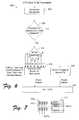
- FIG. 3is block diagram depicting a weighting multiplier function and associated far field transmission pattern amplitude associated therewith, in accordance with certain exemplary implementations of the present invention.
- FIG. 4is an illustrative diagram showing the reception and weighing of various signals by the wireless routing device, for example, as in FIG. 2 .
- FIG. 5 A and FIG. 5Billustrate exemplary antenna array panels and graphs that illustrate an approximate uniform distribution pattern associated therewith.
- FIG. 5Cis a block diagram depicting an antenna array panel, for example as in FIG. 5A, that is coupled to a plurality of receivers/transmitters and various input weighting value pairs.
- FIG. 5Dis a block diagram depicting logic, including a search receiver, that is operatively coupled to a plurality of receivers/transmitters, for example, as in FIG. 5 C.
- FIG. 6is a flow diagram depicting a process for selectively developing CTS is transmission beams, in accordance with certain exemplary implementations of the present invention.
- FIG. 7illustrates an antenna array panel having different polarized elements, in accordance with certain exemplary implementations of the present invention.
- FIG. 8Ais a block diagram depicting a transmission path and reception path configured to reduce unwanted coupling between antenna elements, in accordance with certain exemplary implementations of the present invention.
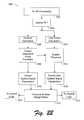
- FIG. 8Bis a flow diagram depicting a process associated with FIG. 8 A.
- FIG. 9Ais a block diagram depicting a transmission path and reception path configured to reduce unwanted coupling between antenna elements, in accordance with certain further exemplary implementations of the present invention.
- FIG. 9Bis a flow diagram depicting a process associated with FIG. 9 A.
- FIG. 10Ais a block diagram depicting a transmission path and reception path configured to reduce unwanted coupling between antenna elements, in accordance with certain other exemplary implementations of the present invention.
- FIG. 10Bis a flow diagram depicting a process associated with FIG. 10 A.
- FIG. 11 A and FIG. 11Billustrate the use of a barrier with an antenna array panel configured to reduce unwanted coupling between antenna elements, in accordance with certain exemplary implementations of the present invention.
- FIG. 12is a graph depicting exemplary polarized channels within a two-band, multibeam and multi-frequency system, in accordance with certain implementations of the present invention.
- FIG. 13is a block diagram depicting three nodes within a wireless routing network and a plurality of scattering objects, in accordance with certain exemplary implementations of the present invention.
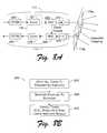
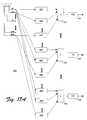
- FIG. 14is a block diagram depicting a hierarchical structure of various nodes within a wireless routing network, in accordance with certain exemplary implementations of the present invention.
- FIG. 15is a flow diagram depicting an exemplary reciprocal and feedback process, in accordance with certain implementations of the present invention.
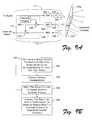
- FIG. 16Ais a graph depicting an approximation of a far field pattern having a desired peak at a first location and another beam having a peak at a nulled location of the far field pattern, in accordance with certain exemplary implementations of the present invention.
- FIG. 16Bis a block diagram depicting several transmission paths having spatial processing logic that is operatively coupled to a corresponding plurality of digital to analog converters, in accordance with certain exemplary implementations of the present invention.
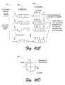
- FIG. 16Cis a block diagram depicting spatial processing logic that includes a finite impulse response (FIR) filter, in accordance with certain exemplary implementations of the present invention.
- FIRfinite impulse response
- FIG. 16Dis a graph illustratively depicting zeros/nulls selectively placed around a unit circle.
- FIG. 16Eis a block diagram depicting a cascaded set of CORDIC stages in an FIR filter, in accordance with certain exemplary implementations of the present invention.
- FIG. 16Fis a block diagram depicting an iterative CORDIC stage in an FIR filter, in accordance with certain further exemplary implementations of the present invention.
- FIGS. 17A and 17Bare block diagrams depicting spatial processing logic, in accordance with certain exemplary implementations of the present invention.
- FIG. 18is a block diagram depicting scheduling logic, in accordance with certain exemplary implementations of the present invention.
- FIG. 19is a graph illustratively depicting a traffic schedule associated with scheduling logic, for example, as in FIG. 18, in accordance with certain exemplary implementations of the present invention.
- FIG. 20is a graph depicting scheduled transmissions, with respect to angle, frequency and time, in accordance with certain exemplary implementations of the present invention.
- FIG. 21is a functional block diagram depicting an exemplary process flow for use in scheduling and transmitting data packets, in accordance with certain exemplary implementations of the present invention.
- FIG. 22is a functional flow diagram depicting various processing associated with an exemplary search receiver process, in accordance with certain exemplary implementations of the present invention.
- FIG. 23is a functional flow diagram depicting various exemplary functions performed within an OFDM receiver path and an OFDM transmitter path, in accordance with certain implementations of the present invention.
- FIG. 24is block diagram illustratively depicting a wireless routing network wherein dual band, dual protocol OFDM/OFDMA techniques may be implemented to overcome the presence of obstacles between a wireless routing device and a CPE device, in accordance with certain implementations of the present invention.
- a wireless routing networkis provided.
- the wireless routing networkwould include at least one wireless routing device that is configured to communicate over a wireless communication link with at least one consumer premise equipment (CPE) device. It is expected, however, that most implementations of the wireless routing network will include a plurality of wireless routing devices and CPE devices.
- CPEconsumer premise equipment
- the wireless networkincludes a plurality of wireless routing devices, then at least a portion of the wireless routing devices are configured to communicate with one another over wireless communication links.
- some of the wireless routing devicesmay also be connected together via a wired communication link.
- WLANwireless local area network
- WANwireless wide area network
- MANwireless metropolitan area network
- the wireless routing networkprovides improved performance over conventional wireless network arrangements by utilizing multibeam receiving/transmitting adaptive antennas, when practical.
- simultaneous transmission and receptionmay occur at a wireless routing device by applying multichannel techniques.
- techniquesare provided for scheduling and conducting operations even in the presence of either self-interference and/or external interferences.
- novel storage and discovery techniqueshave been developed that allow spatial information about the network's nodes, coverage areas and/or potential interference signals to be collected. Accordingly, the wireless routing network provided herein represents a significant improvement over conventional wireless networks that use switched beam and/or omnidirectional antennas.
- the terms “adaptive antenna”refer to an arrangement that includes an antenna array having a plurality of antenna elements, and operatively supporting mechanisms (e.g., circuits, logic, etc.) that are part of a wireless routing device and configured to produce a transmission pattern that selectively places transmission nulls and/or peaks in certain directions within an applicable coverage area.
- a transmission peakoccurs in the transmission pattern when a not insignificant amount of energy is directed in a particular direction.
- Transmission peaksare, therefore, preferably associated with the path and/or multipaths to a desired receiving node, such as, e.g., another wireless routing device or a CPE device. In some cases, sidelobes may also be considered to represent transmission peaks.
- a transmission nulloccurs in the transmission pattern when no transmission of energy occurs in a particular direction, or a relatively insignificant amount of energy is transmitted in a particular direction.
- a transmission nullis preferably associated with the path or multipaths towards an undesired, possibly interfering, device and/or object. Transmission nulls may also be associated with the intent to maximize power in another direction (i.e., associated with a transmission peak), increase data integrity/security, and/or save power, for example.
- the decision to place a transmission null and/or peak in a particular directionis preferably made based on collected (or otherwise provided) routing information.
- the routing informationmay include a variety of data associated with the operation of a wireless routing device and other devices at other locations or nodes within the wireless network.
- logicrefers to hardware, firmware, software, or any combination thereof that may be implemented to perform the logical operations associated with a given task. Such, logic may further include any supporting circuitry that may be required to complete a given task including supportive non-logical operations. For example, “logic” may also include analog circuitry, memory, input/output (I/O) circuitry, interface circuitry, power providing/regulating circuitry, etc.
- I/Oinput/output
- FIG. 1depicts an exemplary wireless routing network 100 having two wireless routing devices 102 a-b and three CPE devices 106 a-c .
- wireless routing device 102 ais operatively coupled to an external network 104 .
- wireless routing device 102 ais connected to network 104 via a wired communication link.
- External network 104may be any type of network from which information (e.g., in the form of data packets) is received and to which similar information can be provided.
- external network 104includes the Internet.
- wireless routing device 102 ais configured to communicate over wireless links with CPE devices 106 a and 106 b .
- wireless routing device 102 bis configured to communicate over a wireless link to CPE device 106 c.
- CPE devices 106 a-care representative of any device that is suitable for use in receiving and transmitting information over the applicable wireless link.
- a CPE devicemay include a computer or other like device having the requisite communication interfaces.
- FIG. 2depicts an exemplary wireless routing device 102 having an adaptive antenna comprising an antenna array 110 and control logic 112 .
- Antenna array 110 and control logic 112are both coupled to a receiver 114 and a transmitter 116 .
- a communication interface 118is also provided and coupled to receiver 114 and transmitter 116 .
- a blockis provided to represent the routing information 120 . It should be understood, however, that although illustratively depicted within logic 112 , routing information 120 may be maintained in an external memory (not shown). Note that there can be more than one receiver and more than one transmitter. By way of example, in certain implementations a dedicated receiver/transmitter pair is associated with each antenna element within the antenna array.
- transmission peakshave been selected so as to illuminate buildings 124 and a mobile user 126 with transmitted energy
- transmission nullshave been selected so as to not significantly illuminate an external transmitter 128 and a residence 130 with any significant amount of transmitted energy even though they are located within a potential coverage area 132 .
- information in the form of data packetscan be routed through wireless routing network 100 .
- Routing information 120may, for example, include desirable transmit power level information, transmit data rate information, antenna pointing direction information, weighting information, constraints information, null/zero location information, peak location information, Quality of Service information, priority information, lifetime information, frequency information, timing information, user and node authentication information, keep out area information, etc., that is associated with each sending/receiving node within the network, or interferers, and the like.
- at least some of routing information 120is maintained within one or more routing tables or like data structure(s).
- the purpose of the routing table(s)is to have a storage mechanism that is capable of providing a highly reliable wireless link in the presence of interference and with a provision for a minimization of interference generated. This is important, because the capacity of the wireless network is often limited by the amount or level of interference present. With the adaptability and control techniques provided in the present invention, such limitations may be reduced and most of the effects associated with such interferences ameliorated.
- the routing table(s)also provides the capability for each routing decision to be based on a point-to-point wireless system design.
- routing table(s) entriesmay include all or part of the following information:
- IP address(e.g., IPv6) of a node in the wireless network—e.g., as an index
- 48-bit unique addresse.g., IEEE 802.1 MAC address
- Protocol IDe.g., IEEE 802.11, 802.16.1, etc.
- Connection IDof a node—e.g., as used in an IEEE 802.16.1 MAC,
- Nominal direction to a nodee.g., one or two dimension
- Nominal channelto receive on, and perhaps a backup channel
- Nominal transmission data ratee.g., 6 Mbps—54 Mbps, or as available
- Nominal receive data ratee.g., 6 Mbps—54 Mbps, or as available
- the routing table(s)is configured to receive/include data and/or primitives (e.g., function calls) from an Internet Protocol (IP) layer and a medium access control (MAC) layer, and instruct a physical (PHY) layer to provide media access through the MAC layer.
- IPInternet Protocol
- MACmedium access control
- the routing table(s)is more than simply a data table(s) (or other like structure(s)) since it may also perform or otherwise support certain controlling and/or scheduling functions.
- the PHY and MACare configured to update entries in the routing table(s) on a dynamic basis utilizing the discovery techniques provided herein. For example, techniques associated with a search receiver as described in subsequent sections.
- pattern amplitudesfor example, as a function of azimuth and/or elevation angle.
- Such patternsmay also be described as a function of a sampled data element weighting function or weighting vector associated with the excitation of the elements in antenna array 110 .
- a portion of an exemplary pattern amplitude 150is depicted in FIG. 3 along with an exemplary weighting factor multiplier 152 .
- Each of these illustrationsrepresents a description of the form of the pattern or weighting that may be stored in the routing table(s).
- the routing table(s)may store such weighing patterns as a function of ⁇ , or the zeroes of the polynomial, for example.
- zero storageOne advantage of zero storage is that the zeros represent directions that should be nulled out to prevent self-interference or possibly interfering with other nodes or possibly other known wireless communication systems, such as, e.g., a WLAN that is not part of wireless routing network 100 but is operating within at least a portion of potential coverage area 132 and frequency bands.
- a WLANthat is not part of wireless routing network 100 but is operating within at least a portion of potential coverage area 132 and frequency bands.
- the polynomial expansion in z, w(z) and the zeroesmay be calculated from each other; therefore, each may be stored. Updates preferably occur fairly frequently (e.g., in certain implementations, about every millisecond), so a zero storage system may be more advantageous as it is expected that in most environments only a few values will change at a given time. Storing the weighting values will in general require changes to all of the weighting values w(i) when any change in the pattern occurs.
- w(i) and A( ⁇ )may be expressed as Fourier transform pairs (discrete due to the finite antenna element space).
- the w(i)is equivalent to a time domain impulse response (e.g., a time domain unit sample response) and the A( ⁇ ) the frequency response (e.g., an evaluation of w(z) sampled along a unit circle).
- wireless routing device 102 ahas an unobstructed line of sight (LOS) from antenna array 110 to both CPE 106 a and 106 b , but not to CPE 106 c .
- LOSline of sight
- wireless routing device 102 bis located such that its antenna array 110 can effectively illuminate CPE 106 c , either directly (i.e., line of sight) or based on local scattering/diffraction. Consequently, packets that are received by wireless routing device 102 a from network 104 for CPE 106 c , will need to be routed through wireless packet routing device 102 b.
- FIG. 4illustratively depicts signals received by a wireless routing device 102 from different sources.
- signals received from sources 160are desired signals as they are from other nodes within wireless routing network 100 and that signals such as the noise and WLAN interference associated with another external wireless system 162 , are not desired.
- receivers 114actually provide the received signals to control logic 110 .
- control logic 112includes a search receiver 164 that is configured to update routing information 120 with regard to the received signals.
- search receiver 164may identify information about different classes of interferers (e.g., known and unknown types) within routing information 120 .
- routing information 120includes a connection indexed routing table(s) based on identification information, such as, e.g., address information, CID, etc.
- the routing table(s)includes identifiers of the desired sources and other identifiers for the interferers (Int). Further included in the routing table(s) are stored weighting values (w). Other information such as “keep out” identifiers, which are described in later sections, are also included in this exemplary routing table(s).
- Weighting matrix 166operates so as to apply the latest weighting values to the received signals and also to transmitted signals. In this illustrative example, subsequently received signals will be processed using the most recent weighting values in the weighting matrix.
- wireless routing device 102is essentially configured to control the transmission amplitude frequency band and directionality of data packets to other nodes and assist in reducing the effects associated with received noise and interference (e.g., self interference and/or external interference). This is accomplished with control logic 112 within wireless routing device 102 .
- noise and interferencee.g., self interference and/or external interference
- Control logic 112is further configured to schedule the timing of transmissions and receptions. Indeed, in certain implementations, control logic 112 is configured to operate in an intelligent manner so as to not interfere with other wireless systems such as, for example, WLAN 162 . One way to accomplish this added benefit is for search receiver 164 to further identify appropriate times for transmission of signals that might otherwise interfere with the other system.
- Time division duplex (TDD) techniquescall for transmissions and receptions to occur over the same frequency band.
- Conducting TDD in a multibeam transmitting systemintroduces a problem in that reception cannot occur when any beam is being used for a transmission. Since TDD reuses the same antenna, the transmit-receive interference tends to be severe.
- Recent contributions to the IEEE 802.16 MAC for multibeamraise the case of TDD in multibeam but do not provide a solution.
- a radio resource managing mechanism or search receiver(not shown here, but included in control logic 112 ) can be configured to identify the IP packet stream that has the highest quality of service (QoS) and/or packet transmission usage, and then consider this stream the “primary” stream.
- QoSquality of service
- secondarystreams may simultaneously transmit on the same antenna array.
- other streamsmay be identified and considered as being the “primary” stream.
- CTSclear to send
- a settable duty cyclecan be employed to allow reverse traffic to occur. By establishing numbers for a duty cycle on a priority basis, for example, the contention and reverse link can be made available.
- RTSrequest to send
- all routing devices within the RTS/CTS networkcan be configured to work in the same manner.
- interference nullsmay be used to reduce simultaneous un-synchronized transmissions.
- the previous solution/systemmay be further expanded to have a pair or more of spatially separated wireless routing devices at one location or node. For example, a separation of about 20 wavelengths may be provided between antenna arrays.
- the routing devicescan allow a higher percentage of receive time using one of the antenna arrays, and also provide the potential of simultaneous transmit streams from the same approximate site.
- MIMOMultiple Input Multiple Output
- mesh forwarding and transmit/receive antenna separationmay all be provided simultaneously.
- transmit and receivemay be swapped for improved diversity reception.
- MIMOmesh forwarding, simultaneous transmit/receive using TDD and spatial diversity may be implemented.
- CCAClear Channel Assessment
- wireless routing device 102may be configured to cross-correlate headers within packets. Therefore, the potential for contention during access can be reduced by having wireless routing devices that essentially listen and cross-correlate headers. If a header is received, then wireless routing device waits a period of time before transmitting.
- the header receive sensitivitymay be somewhat greater than the data sensitivity.
- TDMAtime division multiple access
- Adaptive antennasmay further aggravate collisions that occur during contention periods, subsequent uplinks, and/or receptions in a peer-to-peer network. This is often the result of clear channel assessment failures when transmitting nodes do not hear each other.
- CCAhas three modes of operation, power level (energy detection), carrier sense with timer, and/or a combination thereof.
- One solution to this problemis to add an adaptive antenna at the receiving node and configure it to reject the nearby interference (e.g., nearby in angle).
- the size of such an antennacan become very large because the redirection of nearby angles, for line of sight propagation, is proportional to ⁇ /L in radians, where L is the width of the receiving antenna array panel.
- An exemplary adaptive antenna panel 170is depicted in FIG. 5A, as having a plurality of antenna elements 172 (arranged “vertically” in this example).
- the accompanying graphillustrates an approximate uniform distribution pattern 174 associated with antenna panel 170 . Other distributions may be performed.
- FIG. 5 BOne possible solution involves the placement of a second antenna array panel next to the first, for example, as depicted in FIG. 5 B.
- the pattern of the antennais approximated by line 176 .
- Line 174is also depicted for comparison.
- Signalsare preferably placed at point 178 , with a ⁇ /2S angle off boresight separation 180 .
- closely-spaced nullsmay be placed within the beam of any individual antenna element. Adjustment of the relative phase of the two antenna arrays moves the reception/transmission nulls and peaks across the main aperture shape represented by line 174 .
- antenna elements 172may be selectively configured to operate as transmit and/or receive antennas.
- two antenna elementsmay be simultaneously transmitting on the same or separate frequencies, either to non line of sight nodes, for example, using local diffracting scatterers (same frequency) or using the phasing technique as described above, but now in the transmit mode. Additionally, both antenna elements may be used in receive mode as previously described.
- one antenna elementmay be configured to transmit while another antenna element is configured to receive, but on a separated frequency band so as to prevent adjacent channel power from significantly coupling to the receiving antenna element.
- a plurality of antenna arraysmay also be employed in the same way to further extend performance.
- nulling of potentially colliding data packetscan be achieved, for example, through the use of fast Fourier transforms (FFTs) (e.g., for signal processing and searching for direction of arrival (DOA)), a COordinate Rotation DIgital Computer (CORDIC) algorithm (for trigonometric calculations), and a flexible aperture distribution.
- FFTsfast Fourier transforms
- CORDICCOordinate Rotation DIgital Computer
- Aperture distributionis preferably chosen, in such examples, to change the frequency of the angular peaks/nulls (or spacing of peaks/nulls) to improve interference reduction.
- the deployment of one antenna arraymay be possible. All of the aperture illumination possibilities will exist, however, with resulting wider peak/null spacing.
- Unwanted couplingmay also be reduced/controlled by varying the aperture of the antenna array.
- each of the “vertical” columns of antenna elementsare driven together within the antenna array.
- illuminating only a smaller selected portion of an antenna arraymay prove to be advantageous, since doing so tends to provide a “quiet” area for nearby receive elements.
- One drawbackis that the forward gain will be reduced. By way of example, in certain implementations there is about a 3 dB reception loss and about a 3 dB transmission loss.
- FIG. 5Cdepicts antenna array 170 having a plurality of antenna elements 172 .
- Antenna elements 172are operatively coupled to corresponding receivers/transmitters 182 .
- each of the columns of elementsis utilized during transmission and reception as a result of the positive weighting values associated with each column.
- the second set 184 bdemonstrates a modified use of the columns of elements during transmission and reception.
- half of the columnsare weighted for transmitting signals.
- the remaining half of the columnsare weighted for receiving signals.
- the hardware to accomplish this type of partial element illuminationis in place in a conventional TDD transmit/receive RF elements, with the a modification that some of the receivers need to operate while the other columns of elements are transmitting.
- the reason for the lower gainis due to the smaller aperture illumined by the modified receive/transmit simultaneous arrangement.
- this type of simultaneous receive/transmitallows for the reception of acknowledgement (ACK) signals, Contention Frame END (CF-END) signals, and other like control signals associated the MAC, while simultaneously transmitting out of the same antenna array 170 .
- ACKacknowledgement
- CF-ENDContention Frame END
- Coupling between the receiving and transmitting columns of elementscan be controlled, for example, through a combination of isolation and OFDM tone reduction to allow for sensitive reception of the control signals.
- the element illuminationneed not be equal between transmit and receive.
- more columns of elementsare weighted for transmission than receive. This is useful in situations where the gain of the receiver or of the transmitter is needed separately for the link budget.
- the resulting receiver “illumination”can be used to describe element weighting in the sense of the Lorentz reciprocity theorem, i.e., that all current weightings of the receive array are equivalent to the transmit illumination.
- variable illuminationmay be performed, when needed, for example, when a control node is being sought by a receiving node.
- Each of the multiple transmit beams produced by the antenna arraymay be separately illuminated to further reduce unwanted receive signal coupling. Beams on adjacent channels may be fully or partially illuminated to reduce the likelihood of out of band signals appearing on a received signal. Alternate (i.e., non-adjacent) channels typically do not couple as much energy as an adjacent channel and thus should not require as much reduction in antenna gain through partial illumination.
- the element weightingmay overlap if reception/transmission is capable of being conducted simultaneously. Furthermore, as shown, the element weighting values need not be uniform.
- FIG. 5Da plurality of receivers/transmitters 182 area depicted as being operatively coupled to logic 112 , which includes receiver/transmitter sharing resource 190 and search receiver 164 .
- a first subset 192 of receivers/transmitters 182 and associated antenna elements 172are configured to transmit and a second subset 194 of receivers/transmitters 182 and associated antenna elements 172 are configured to receive.
- Search receiver 164 in this exampleis configured to operate on the base band element data to extract information from received signals, such as, e.g., PLCP headers that are received from any direction, within the element pattern.
- search receiver 164includes at least one FFT (not shown) performing spatial conversion from the element domain to an angle domain. This “spatial FFT” can be configured, as in this example, to only process signals from the elements that are in the portion of the array that is “quiet” with regard to the transmitted signals.
- Receiver/transmitter sharing resource 190is configured to selectively control the operating mode, i.e., transmit mode and receive mode, of each of the receivers/transmitters 182 .
- Antenna element orientationmay produce linear or circularly polarized signals polarized.
- laptop computers with wireless PCMCIA cardstend towards a horizontal polarization pattern.
- the elements in the antenna arraymay be rotated to provide an optimum horizontally polarized signal, or diagonal polarization.
- Circular polarizationmay be used to prevent nulls from appearing in the signal pattern. Reflection from oblique surfaces tends to change the sense of linear polarization. Circular polarization is usually right-hand-sense to left-hand-sense converted on reflection. Therefore, a circular polarized to linear polarized signal will likely sacrifice about 3 dB for a reduction in polarization cancellation upon reflection.
- the beam shape of the CTS alertmay be omnidirectional or directed.
- Omnidirectional transmissionwhich will likely cause more interference, currently requires a lower Federal Communications Commission (FCC) power limit due to point-to-multipoint rules and therefore results in directed beams from node A to node B during CTS, for example.
- FCCFederal Communications Commission
- a simplified approachis to retain information on the effectiveness of the node A to node B path for particular node A to node C beams generated, and use the normal sidelobes of node A to ensure that node B receives the CTS that node A is sending to node C.
- the nulling techniques available at node Amay then be used to reject interference coming from node B.
- Knowledge of node B's interference generation at node Ain some cases allows node A to not send the CTS to node B at all. In this case, node B must adhere to known beam shapes that have adequate nulls toward node A.
- FIG. 6depicts a flow diagram of a process 200 associated with the above techniques.
- Process 200may, for example, be implemented in control logic 112 .
- the CTSis about to be transmitted.
- the neighboring nodesare ascertained, for example, from stored historical routing information.
- step 204a decision is made as to whether there is a potential for interference from a neighboring node. If it is determined that there is no potential for significant interference, then in step 206 a narrow CTS power beam is developed and then transmitted in step 208 . Conversely, if it is determined in step 204 that there is a potential for significant interference, then another decision is made in step 210 to determine which nodes to transmit to.
- step 212there are seven nodes, numbered 0-6, of which only nodes 1 and 2 are not to receive to the CTS.
- step 212applicable beam(s) are developed for the CTS transmission.
- step 208the CTS is transmitted.
- an omnidirectional or like transmissionmay be used, otherwise if there is only a few receiving nodes, then a narrower beam may be used to transmit the CTS message.
- CTS signalsare an example of control signals used to control subsequent transmissions.
- Other signals that establish transmission queuing and back-off timesmay be used.
- a point coordination function or a hybrid coordination functionmay be employed.
- One solution to this problemis to separate the receive and transmit frequencies adequately enough to reduce the leakage by filtering. At that point the receive and transmit antennas may be combined, thereby possibly reducing the size of the requisite antenna array panel.
- the FCChas indicated acceptance of point-to-point links using steered beams in the 5.7 GHz U-NII band up to 1 watt with a 23 dBi gain antenna.
- the 5.3 GHz U-NII outdoor/indoor bandonly allows 0.25 watts to a 6 dBi antenna. If a 6 dBi antenna is used for the transmission and reception of the 5.3 GHz node, then the 5.3 GHz link has a 40 dB disadvantage compared to the 5.7 GHz link.
- the 5.7 GHz linklikely may increase the receiving antenna gain beyond 23 dBi, requiring a larger antenna.
- the 5.3 GHz receiving antennacan easily increase phased array gain above 6 dBi. Phased arrays at these frequencies commonly reach much higher gains and tend to be compact. Therefore, unfortunately, the 5.3 GHz link may have a link disadvantage somewhat greater than 20 dBi.
- the 5.7 GHz reverse signalmay be spread to allow it to be effective below the noise of the spurious signals generated by the alternate channels.
- the MAC of the 5.7 GHz transmittermay be programmed to provide an interval of quiet time equal to at lease twice the maximum expected propagation delay.
- a distant nodecan then listen to the forwarded signals from the 5.7 GHz transmitter, waiting for a quiet time alert, and then begin transmitting on a determined quiet 5.7 GHz channel that is reversed for this purpose.
- a multibeam wireless routing device using a phased arraytransmits beams in several directions and may not be able to alert all nodes that a quiet time is about to occur. However, a very brief transmission to all potentially transmitting nodes, e.g., those that do not have high signal to noise ratio SNR return links, is possible. In other words, the quiet time alert generated by the MAC need only be sent out only in the directions needed by those nodes operating their transmitters on 5.7 GHz.
- the use of 5.3 GHz for the reverse linkalso frees up the 5.7 GHz band for additional transmissions from the 5.7 GHz receiving nodes, when a node has not received an RTS.
- the overall network capacityis actually increased because the 5.7 GHz band may be reused, for example, by node B to transmit to node D which may be out of range of node A.
- the lack of an RTS or other announcement of 5.7 GHz signals that may be received by node Ballows node B to re-use the frequency or frequencies within the 5.7 GHz band.
- the resulting network/nodesmay employ FDD, TDD, frequency simplex division duplex (FSDD), or other like techniques.
- the routing table(s) or like routing information structure(s) used by each wireless routing device 102would therefore, include the information that is dynamically generated and which preferably tends to optimize communication with nearby nodes.
- an algorithmmay be used to handle node D, due to it being a weak node, (e.g., being unable to respond on 5.3 GHz).
- node Dmay respond to the wireless routing device at 5.7 GHz while one channel is sufficiently quiet to get a signal through.
- all signalsmay be single carrier, orthogonal frequency division multiplexing modulation (OFDM), or spread spectrum.
- OFDMorthogonal frequency division multiplexing modulation
- a signalhas a higher probability of being received through interference.
- one disadvantageis that the data bit rate tends to be lower for the same occupied bandwidth.
- FIG. 7Another solution to the reverse link in the same frequency band is to select opposite polarization within an antenna array. This is depicted in FIG. 7, for example, wherein an antenna panel 170 c includes “vertical” polarization elements 172 and “horizontal” polarization elements 173 . Given this configuration, selective use of the opposing polarized elements in antenna array will allow for nulling to occur during transmission, thus allowing the re-use of the 5.7 GHz band.
- the artifacts of unwanted coupling between an applicable transmitter 116 and receiver 114 at antenna array 110can be reduced by recognizing the artifacts in the received signal and significantly canceling them out. Doing so effectively will allow for selected simultaneous transmission and reception at the same frequency.
- a delayed version of the transmitted signalis digitally subtracted from the received signal to remove undesired coupling artifacts.
- the block diagram in FIG. 8Aillustratively depicts a transmission path 117 and reception path 115 , which are both coupled to transmit antenna elements 170 e and a receive antenna elements 170 f , respectively.
- Transmission path 117includes an OFDM modem 220 that converts data to be transmitted into a corresponding OFDM data.
- the OFDM datais then provided to spatial processing logic 221 , which is configured to establish the applicable peaks and nulls for the transmission.
- the resulting spatially processed OFDM datais then provided to the input of a digital to analog converter (DAC) 222 , wherein a corresponding analog signal is produced.
- DACdigital to analog converter
- the output of DAC 222is then provided to an up converter 224 , which prepares and amplifies the analog signal for transmission and provides the resulting adaptive array signals to transmit antenna elements 170 e.
- Reception path 115includes a down converter 226 , which is configured to process the signal received by antenna elements 170 f .
- the output of down converter 226is provided to an analog to digital converter (ADC) 228 , which converts the analog signal from down converter 226 .
- ADCanalog to digital converter
- the resulting digital data output from ADC 228is then provided to spatial processing logic 229 for further spatial processing.
- the resulting spatially processed datais then provided to an OFDM modem 230 for further conversion.
- antenna elements 170 e and 170 fthere may be unwanted coupling between antenna elements 170 e and 170 f .
- this unwanted couplingmay be reduced through cross-coupling which essentially subtracts each OFDM tone from the resultant received data.
- noise signals associated with the sidebands in the transmitted signalcan be significantly canceled out.
- This sideband noiseis essentially deterministic based on an amplifier model and having the transmitted signal itself applied to the amplifier model.
- FIG. 8Bis a flow diagram that further illustrates a process 240 associated with this type of delayed cancellation technique.
- step 242all of the tones are applied to up converter 224 .
- step 244the coupling to reception path 115 is measured by cross-coupling the output of DAC 222 to ADC 228 .
- step 246the OFDM tones based on a non-linear amplifier model are cancelled out, for example, within ADC 228 .
- another similar delayed cancellation techniqueincludes measuring each OFDM tone that is being transmitted with an auxiliary receiver, and then canceling out measured/scaled tones in the received signal. In this manner, the actual substantially instantaneous adaptive array signals are measured and then cancelled out.
- the cancellation of unwanted tonescan be based on learned scale factors provided by a deriving engine.
- FIG. 9Aillustrates an exemplary arrangement for accomplishing such tasks.
- a directional coupler 260 or like mechanismis configured to tap into the output (i.e., the adaptive array signals) from up converter 224 in transmission path 117 .
- a sampled adaptive array signalis then provided, as shown in this example, to an auxiliary receiver that includes a down converter 262 and an ADC 264 .
- the output from amplifier 262is provided to ADC 264 .
- the output of ADC 264is then provided to a multiplier 266 , wherein the digital signal is scaled according to scale factors provided by a deriving engine 268 .
- Each of the scale factorsis associated a different OFDM tone and determined or learned by deriving engine 268 during a testing phase wherein all of the tones are transmitted and the resulting coupling at the antenna panel is measured. In certain implementations, for example, a short testing phase is conducted every few minutes or so.
- the output from multiplier 266is then provided to a negative input of a combiner 270 and therein combined with the output from ADC 228 , which is the digital equivalent of the received signal as processed by down converter 226 .
- ADC 228the digital equivalent of the received signal as processed by down converter 226 .
- the scaled tones associated with the tapped transmission signalare significantly removed from the received signal to produce a substantially “clean” received signal. This can be accomplished for each adaptive array signal.
- FIG. 9Billustrates an exemplary process 280 for the above technique.
- step 282during a testing phase, the coupling between antenna panels is detected for each OFDM tone by transmitting all OFDM tones, and corresponding scale factors are determined.
- step 284normal transmissions are conducted and adaptive array signals are tapped.
- step 286the scale factors are applied to the tapped signals to produce corresponding scaled tapped adaptive array signals.
- step 288the scaled tapped adaptive array signals are then combined with corresponding received signals, thereby causing unwanted coupling from the transmitted signals to be significantly rejected. The resulting “clean” receive signals can then be further processed as required.
- unwanted couplingmay be significantly reduced by instead modifying OFDM tones in transmitter 116 , prior to transmission.
- An exemplary arrangement for accomplishing this taskis depicted in FIG. 10 A.
- a tapped adaptive array signal(which has been digitized by ADC 264 ) is scaled, as in the previous example, by multiplier 266 using a learned scale factor, for example, as determined by deriving engine 268 during a testing phase. Then the resulting scaled tapped adaptive array signal is then fed back to a combiner 290 in transmission path 117 .
- the resulting combination of the signal to be transmitted and the scaled tapped adaptive array signaltends to reduce unwanted coupling between the antenna elements 170 e and 170 f when the adaptive array signal from up converter 224 is subsequently transmitted.
- FIG. 10Bis a flow diagram depicting an exemplary process 300 for reducing unwanted coupling between transmit antenna elements 170 e and receive antenna elements 170 f .
- a scale factoris determined for each OFDM tone based on unwanted coupling detected during one or more test phases.
- normal transmission of at least one adaptive array signalbegins.
- the scale factor determined in step 302is applied to a tapped and digitized version of the adaptive array signal in step 304 .
- the resulting scaled tapped adaptive array signal in step 306is then fed back and combined with the digital signal, which is subsequently being transmitted as the adaptive array signal.
- the combining process in step 308is configured to produce a modified digital signal that is then converted to an analog signal by DAC 222 and further processed by up converter 224 to produce a modified adaptive array signal.
- the modified adaptive array signalis transmitted using antenna elements 170 e and is also tapped in accordance with step 306 .
- the transmission of the modified adaptive array signalsignificantly reduces unwanted coupling and associated artifacts within signals received using antenna panel 170 f.
- introducing electromagnetic absorbing and/or reflecting materials near to the antenna elementscan reduce unwanted coupling between a receiver and transmitter.
- the illustration at the top of FIG. 11Ashows a barrier 310 that includes electromagnetic absorbing and/or reflecting materials.
- barrier 310essentially divides antenna array 170 g into two portions. When maximum isolation is required between a receiver and transmitter, then the receiving and transmitting elements should be selected such that they are separated by barrier 310 .
- the illustration at the bottom of FIG. 11Aillustrates that all (or part of) antenna array 170 g may be enclosed by a similar barrier 312 .
- FIG. 11Bdepicts a cross section of an exemplary barrier 314 suitable for use as barriers 310 and/or 312 .
- Barrier 314includes both electromagnetic absorbing and reflecting materials.
- the electromagnetic reflecting materialis provided by member 316 , which includes at least one reflecting surface 317 a and/or 317 b .
- reflecting surfaces 317 a-bcan be metallic surfaces.
- member 316may be comprised of metal.
- the electromagnetic absorbing materialis represented by electromagnetic absorbing foam members 318 a and 318 b , which sandwich member 316 in this example.
- barrier 314may include just one of the foam members 318 a-b.
- the coupling between the receiver and transmitteris reduced with the use of barriers, such as, barriers 310 , 312 and 314 , because the capacitance between antenna elements is reduced, and essentially a “shroud” is placed so as to reduce the unwanted effects of the sidelobes.
- the transmission patternis changed, however, such that the forward gain is reduced due to the lower aperture, and sidelobes are increased.
- compensation of the zero locationsis required when the overall antenna array is illuminated. Compensation can be accomplished, for example, by computing the zero locations with the presence of the barriers (i.e., blockage), or by using a search system (e.g., having a Wiener spatial filter) to optimize the zero location for a reduction in interference.
- This second approachmay, for example, utilize PLCP cross correlation detection techniques and the total power connected to the output of an FFT measuring spatial (angular) response.
- Certain implementationsinvolve the use of a PLCP/header/preamble cross-correlation process to determine the timing of arriving packets.
- the signals to be cross-correlatedare output from an orthogonal spatial FFT calculation.
- a Wiener filter, least mean squares and/or other like methodmay be used to further improve the SNR, e.g., by optimizing the weighting coefficients.
- Such process(es)may be performed as a packet is being received and applied to a decoding process. Decoded data may be used to determine the desired signal, applied to a Wiener filter, least mean squares algorithm, or the like.
- the above polarization nulling, delayed cancellation and quiet time techniquescan be advantageously combined to allow the use of adjacent and alternate channels within the same frequency band to improve the utilization of the associated frequency spectrum.
- FIG. 12is a graph 320 depicting polarized channels within a two-band, multibeam and multi-frequency system.
- the first band 322is a 5.3 GHz receive band that extends from 5.25 to 5.35 GHz
- the second band 326is a 5.7 GHz transmit band that extends from 5.725 to 5.825 GHz.
- a plurality of channels 324that include both horizontal (H) and vertical (V) polarized channels.
- the second band 326there are a plurality of channels 328 that include both H and V polarized channels.
- one of the goalsis to implement the previous techniques so as to make full use of the available bandwidth for outgoing transmissions, while also supporting simultaneous reception of incoming transmissions to wireless routing device 102 when possible.
- wireless routing device 102initially transmit outgoing adaptive array signals using both H and/or V polarizations, with multiple beams per channel, within the 5.7 GHz band 326 .
- wireless routing device 102would initially be able to receive incoming transmissions from other nodes using H and/or V polarizations, with multiple beams per channel, within the 5.3 GHz band 322 . If the amount of outgoing traffic exceeds the available bandwidth of the 5.7 GHz band 326 , then wireless routing device 102 could begin transmitting adaptive array signals using a portion of the available bandwidth in the 5.3 GHz band 322 .
- all or part of the horizontal (H) polarized channels within the 5.3 GHz band 322will be used for transmitting adaptive array signals, while all or part of the vertical (V) polarized channels will still be configured to receive incoming transmissions from other nodes.
- the resulting horizontal transmit channels and vertical receive channels within the 5.3 GHz band 322are preferably separated by at least one channel and some form of delayed cancellation techniques are employed to reduce unwanted coupling noise in the received signals.
- one or more of the delayed cancellation, polarization nulling and/or quiet time techniquescan be applied to further optimize the communication traffic.
- the combination of these techniquestends to maximize the electromagnetic energy that is received by other nodes.
- the receiving nodeswill, however, need to be capable of receiving all combinations of the polarization (i.e., H and V) within the applicable frequency band(s).
- the complexity of the various nodeswill, therefore, be associated with the number of simultaneous transmit and receive signals that may be generated and received.
- Adaptive antennascan be expensive. However, in an IP routed network 100 having a plurality of wireless routing devices 102 , the traffic capacity of network 100 will usually be increased by using adaptive antennas whenever feasible.
- the directionality of a given adaptive antenna within the wireless networkneed only be high enough to adapt to the direction of arrival (DOA) characteristics for those signals that the associated wireless routing device is concerned with.
- DOAdirection of arrival
- the use of an adaptive antennamay prove to be an overkill at times, especially when there are a number of scattering objects that further extend the associated coverage area.
- the use of an omnidirectional antennamay in certain similar instances prove to be an underkill in that the resulting coverage area may be inadequate.
- FIG. 13is block diagram depicting three nodes within an exemplary wireless routing network 340 and a plurality of scattering objects 348 that are nearby certain nodes.
- IP packets that arrive a node M 342are routed to node N 344 , which further routes the IP packets to Node C 346 .
- node M 342could represent wireless routing device 102 a (e.g., a metropolitan routing device)
- node N 344could represent wireless routing device 102 b (e.g., a neighborhood routing device)
- node Ccould represent CPE device 106 c.
- An antenna arraysuch as, e.g., antenna array 110 in FIG. 2, which is optimized for node M 342 would not likely be optimized for use at node N 344 and/or node C 346 .
- the number of elements in the antenna arraysmay be decreased to better match the antenna array to the local environment's scattering objects 348 .
- the antenna array at node M 342may be capable of providing a 0.1 radian beam width using a 10 ⁇ aperture
- the antenna array at node N 344may provide a 0.5 radian beam width using a 2 ⁇ aperture
- the antenna at node C 346may be an omnidirectional antenna.
- the interference generated by each of the antenna arrays at nodes M and Nshould be minimized in those directions where the given antenna array is to generate a simultaneous second, third beam, etc.
- FIG. 14depicts a similar network 360 having two metropolitan (M) routing devices represented by node M 342 a and node M 342 b .
- node M 342 aprovide wireless connectivity to two neighborhood (N) routing devices represented by node N 344 a and node N 344 b .
- Node M 342 bprovides wireless connectivity to one neighborhood (N) routing device represented by node N 344 c .
- Nodes 344 a , 344 b and 344 care each further configured to provide wireless connectivity to certain client (C) devices selected from a set of client devices represented by nodes C 346 a-f .
- Cclient
- node N 344 aprovides connectivity for node C 346 a ;
- node N 344 bprovides connectivity for nodes C 346 b-d ; and
- node N 344 cprovides connectivity for nodes C 346 e-f.
- the exemplary arrangement of nodesrequires the use of three separate frequency bands to prevent interference between hierarchical levels during IP packet forwarding.
- M-Mnode M to node M
- M-Nnode M to node N
- N-Cnode N to node C
- Several simultaneous transmit beams from node N 344 bare possible.
- interference nullingmay need to be implemented to reduce self-interference.
- at least three separate frequency bandsare preferred for the illustrated network to have sufficient transmit-receive isolation.
- the node N to node C pathswill only represent short range links, which can be achieved using high microwave frequencies, such as, e.g., those within the 5.3 GHz band.
- the node M to node M pathsare generally expected to be point-to-point microwave links, which may be achieved using frequencies within the 5.7 GHz band.
- the node M to node N linksideally should be achievable at a lower frequency, such as, for example, frequencies within a 2.5 GHz band.
- the node N to node C frequenciesmay also be within a 2.4 GHz band.
- a wireless routing networkmay include node N to node N communications, for example, using yet another frequency band and/or a portion of one of the previously described bands.
- an M-N frequency bandmay be established at 2.55 GHz and an N-N frequency band may be established at 2.67 GHz.
- the various wireless communication linksmay be TDD and/or FDD based links. It is also noted, that the various frequencies that are described herein are examples only, and it is fully expected that other frequencies and/or frequency bands may be supported in other implementations.
- wireless routing device 102may simultaneously transmit and receive signals.
- the M-M and M-N linkscan further benefit from reciprocal and feedback methods that provide adaptive interference nulling.
- the wireless routing devices associated with the M and N nodescan be configured such that the PHY and MAC use adaptive nulling wherein the feedback from node M or node N provides information that can be applied to reduce self-interference. Doing so will advantageously increase the data bit rate that can be supported over the corresponding communication links.
- a first wireless routing devicefor example, at a node N, measures the level (e.g., a complex amplitude) of an unwanted signal transmitted from a second wireless routing device located at another node.
- the second wireless routing devicemay be located at a node M that may or may not normally provide connectivity to the node N having the first wireless routing device.
- the first wireless routing deviceprovides information about the measured unwanted signal to the second wireless routing device.
- the informationmay include, for example, the measured level, an identifier and perhaps a location of the first wireless routing device, etc.
- the informationmay be transmitted over a wireless link between the first and second wireless routing devices.
- the two wireless routing devicesmay have another communication link available, e.g., a wired connection, then the information may be passed from the first to the second wireless routing device through this link. In either implementation, the information is provided to the second wireless routing device.
- the second wireless routing deviceselectively applies a low null level in the direction of the first wireless routing device during subsequent transmissions to other nodes, if possible.
- control logic 112(FIG. 2) needs to be configured to selectively place peaks and nulls in certain directions for each beam.
- control logic 112includes spatial processing logic that focuses on determining the appropriate placement of nulls within a desired far field pattern.
- One techniqueis to provide an all zero filter, another technique is to provide a weighting matrix. These techniques can be used together, wherein an all zero filter is used to build a weighting matrix. For example, the weighting inputs to a weighting matrix such as that shown in FIG.
- weighting values or polynomial coefficientscan be generated ahead of time or on-the-fly using an all zero filter, for example. Calculated weighting values can be included, for example, in routing information 120 .
- Graph 420 in FIG. 16Aillustrates a far field pattern 422 having a desired peak at a first location (angle) and another beam represented by dashed line 426 having a peak that is located at a different angle than the peak of far field pattern 422 .
- a null 424 in far field pattern 422is placed at about the angle of the peak of the other beam.
- null 424is required to allow high quadrature amplitude modulation (QAM) modulation, e.g., QAM-64, to be supported with a sufficient SNR, for example, about 25 dB.
- QAMquadrature amplitude modulation
- FIG. 16Billustrates transmission path 117 having a plurality of spatial processing logic 221 operatively coupled to a corresponding plurality of DACs 222 .
- Each DAC 222applies its output to a corresponding up converter 224 , which then provides an adaptive array signal to selected antenna elements.
- spatial processing logic 221is an all zero, or an approximate all zero, finite impulse response (FIR) filter.
- FIG. 16Cdepicts one such example.
- spatial processing logic 221includes two stages 428 and 430 .
- the spatial processingmay be calculated using a spatial filter driven by an impulse, followed by an impulse response capture register driving the DACs. Alternatively, such processing may be performed in parallel by a set of multipliers (not shown).
- the processing stage represented by block 428may be part of an FIR filter that includes CORDIC stages to allow zeros to be placed around the unit circle 432 , for example as illustrated in FIG. 16 D.
- the second stage 430receives the output from the first stage and applies the spatially filtered samples in parallel to the DACs.
- FIG. 16 E and FIG. 16Fdepict two exemplary ways in which CORDIC stages may be used.
- the CORDIC stages 434are arranged in a cascaded arrangement in FIG. 16E, wherein the transfer function of the resulting FIR filter is:
- each stagemay be implemented using delay elements (i.e., the upper blocks).
- the CORDIC stages 434 ′ in FIG. 16Fare configured as part of an iterative system.
- the number of CORDIC stages required per elementdrops from the number(#) of elements per element down to two per element, in accordance with certain exemplary implementations, or N e 2 to 2N e .
- a similar configuration as in FIG. 16 E and/or 16 Fcan be provided for the corresponding receiver functionality, only it would operate in a reverse manner.
- ADCswould be used instead of DACs. Reciprocity may then be relied on to allow the setting of the transmit zeros.
- An FFTmay be used to determine the direction of signals received as a function of angle.
- An exemplary arrangementis depicted by logic 229 in FIG. 17 A and FIG. 17 B. In this manner, both reception and transmission zeros can be determined.
- a plurality of logic blocks 440are shown as receiving selected inputs from the antenna array.
- Logic blocks 440include, for example, CORDIC down converters, scalars and phase shifters (not shown).
- the inputs and outputs for logic blocks 440are depicted in FIG. 17 B.
- Logic blocks 440provide complex multiplication and a frequency shift.
- the computation of the A BBj value and the ⁇ BBj value, which represent the polar value the complex weighting coefficient, for each one of the CORDIC stagescan be determined by the polynomial produced from the expansion of all of the zeros.
- the ⁇ BBj valuesrepresents the carrier frequency to be converted down from a pass band frequency.
- the outputs from logic blocks 440are provided to summers 442 .
- the output of summers 442are provided to FIR filters 444 .
- the processing accomplished in the various logic stages abovemay also be performed on a split basis, wherein zeros that are common between channels are placed in a common filter path. Zeros corresponding to each channel can be separately cascaded to allow a particular response from each channel's required response of angular beam width.
- Logic 112includes a scheduling capability that makes decisions regarding the allocation of resources, for example, based on a demand matrix that identifies both downlink traffic demands and known uplink traffic demands, and/or transmission constraints identified by the search receiver.
- the allocation of resourcesmay include, for example, allocating the CORDIC or like resources that provide the requisite mathematical computations for the signals that are to be transmitted or signals to be received.
- the scheduling capabilityutilizes queues to determine the allocation of resources. Some of the queues may, for example, be associated with certain levels of quality of service (QoS) that are assigned to different data packets.
- QoSquality of service
- FIG. 18A functional block diagram for an exemplary scheduling capability provided by logic 112 is depicted in FIG. 18 .
- Data packets that are to be sent from a wireless routing device (i.e., down linked) to another nodeare associated with a queue 500 , for example, by identifying the data packets in a queue of pointers, placing the data packets in a queue, or other like manner.
- data packets or data traffic that is expected to be received by the wireless routing device from another nodeare also associated with a queue 500 .
- the resulting queues 500 and/or the information thereinmay also be logically arranged or otherwise configured based on a QoS associated with the data packets or a data stream, for example. It is further expected that queues 500 will be arranged based on other priority schemes, such as, a first come first serve scheme, etc.
- the queues 500may also take into consideration a “lifetime” or other time critical information associated with the data packets. Hence, for example, data packets that are about to have their measured lifetime expire, may be moved up in a queue.
- Queues 500are active whenever data packets are waiting to be uplinked or downlinked with regard to the wireless routing device. Based on queues 500 , certain demands 502 are identified, for example within routing information 120 . In certain implementations, for example, demands 502 are maintained in a demand matrix. In the example shown in FIG. 18, the demands 502 include uplink and downlink demands, since these demands will drive the scheduling of transmissions and receptions.
- Routing information 120further includes constraints 504 , such as, for example, the transmission constraints identified by search engine 164 .
- the constraints 504are, for example, maintained in a constraints matrix.
- the constraints 504may include information relating to certain rules for transmissions and receptions, information about discovered and/or historical transmission/reception performance, etc.
- constraints 504includes information about known/unknown interferences that may be pertinent to the scheduling of transmissions/receptions.
- scheduler 506is tasked with generating traffic schedules 508 for transmissions and receptions based, for example, on an angular (or dimensional) parameters and time (or frequency) parameters.
- FIG. 19An exemplary graphical representation of a transmission (downlink) traffic schedule 508 is depicted in FIG. 19 .
- angles associated with the antenna arrayare identified on the y-axis as extending from ⁇ 60° to +60°, in this example.
- the x-axisrepresents time.
- a plurality of transmissionsare scheduled and identified by blocks in the graph, which also identify the associated data transmission rates.
- certain “keep out” areasare also depicted by blocks and marked as such. No significant transmissions should occur within the keep out areas.
- graph 520 in FIG. 20illustrates five different transmissions 522 a-e scheduled within a given period of time, each transmission has associated with it a frequency band and an angle.
- transmission 522 chas a center frequency of ⁇ 0 as marked by dashed line 524 .
- a similar graphmay also be used to illustrate scheduled receptions.
- FIG. 21depicts a block diagram illustrative of an exemplary flow for the scheduling and transmission of data packets, in accordance with certain further exemplary implementations of the present invention.
- scheduler 506is operatively configured to take into consideration QoS and other parameters, for example, relating to the number of subscribers and/or the data packets in queue 500 , peak data rates, sustained data rates, latency, isochronous performance, etc. Based on such parameters, scheduler 506 applies CORDIC FFT/DFT resources 540 a-b and subsequently 544 a-b to the combined angular, frequency and time arrangement of electromagnetic signals.
- CORDIC FFT/DFT resources 540 a-bassist with creating an assignment 542 , which may be included in traffic schedule 508 .
- CORDIC FFT/DFT resources 544 a-bare used to prepare the data for an RF conversion process 546 .
- the resulting adaptive array signalsare then provided to the applicable adaptive array resources 548 and transmitted using all or part of an antenna array.
- scheduler 506may use information from the MAC about the expected signals that are to arrive at the wireless routing device. In certain cases, the MAC may have already assigned reverse resources for use with the reception.
- FIG. 22is a functional flow diagram depicting processing associated with an exemplary search receiver process 600 .
- a receiverprocesses the RF signal received with an antenna array.
- the resulting element domain valuesare provided to step 604 , wherein a spatial FFT process converts them into corresponding pattern domain values.
- the pattern domain valuesare then provided to step 606 , wherein a FFT process or other process, such as, e.g., a pilot cross-correlation process, is employed to estimate the channel.
- the resulting estimated channel datais then provided to step 608 , wherein a known sequence cross correlation process, such as, e.g., a PLCP header preamble or other like information cross-correlation process, is conducted.
- a known sequence cross correlation processsuch as, e.g., a PLCP header preamble or other like information cross-correlation process
- step 610The resultant data from the cross-correlation process is then provided to step 610 in which system signal parameters are extracted. These parameters may then be included or otherwise incorporated in constraints 504 (FIG. 18 ).
- step 612The data is then provided to step 612 , wherein the weighting values are computed and stored, for example, in a weighting matrix.
- the resulting pattern domain dataare also provided to step 614 for a total power calculation, the results of which may be included in or otherwise incorporated in constraints 504 .
- a Wiener filter division or like processis performed in step 616 , with inputs from steps 614 and 608 .
- the resultant datais then provided to step 618 , wherein any non system parameters relative to constraints 504 are extracted and supplied thereto.
- the datais then provided to and utilized in step 612 with regard to the weighting values.
- the search receiveressentially acts as an adaptive filter to optimize/update the weighting values so as to detect the signal indicated by knowledge of the PLCP header or other like information that is cross-correlated.
- the stored weighting valuesare then provided, as applicable, to a transmission spatial logic process in step 620 and/or to a receive spatial logic process in step 622 .
- FIG. 23is a functional flow diagram depicting various exemplary functions performed within an OFDM transmitter path 700 and an OFDM receiver path 702 , in accordance with certain implementations of the present invention.
- receivers/transmitterssuch as, e.g., QPSK receivers and transmitters.
- Transmitter path 700begins with a convolutional encoding process 704 , which receives data to be transmitted and generates corresponding encoded data based on known convolutional techniques. This encoded data is then “punctured” using a puncturing process 706 to produce corresponding punctured data. The puncturing process is configured to modify the encoding rate. Next, the resulting punctured data is interleaved in an interleaving process 708 , which produces corresponding interleaved data. Interleaving process 708 is conducted so as to spread data over a symbol to improve burst error performance.
- a symbol building process 710is then accomplished with the interleaved data to produce corresponding symbolic, constellation mapped, data that is then provided to a pilot insertion process 712 .
- the resulting datais then provided to an inverse fast Fourier transform (IFFT) process 714 and processed accordingly.
- IFFTinverse fast Fourier transform
- the resulting IFFT datais provided to a parallel to a serial conversion process 715 , which prepares the IFFT data for transmission.
- the resulting serial conversion process 715which prepares the IFFT data for transmission.
- IFFT datais then provided to a cyclic extension windowing process 716 , which is configured to insert a guard interval to improve multipath performance.
- the resulting cyclic extended datais then provided to a carrier modulation process 718 to configure the signal for transmission.
- Carrier modulation process 718is configured to upconvert the baseband signal for application to the spatial weighting system.
- receiver path 702data that is received is provided to a channel estimation process 720 , wherein the received data and pilot information is used to equalize the channel response.
- the received datais also provided to a symbol timing/cyclic extension removal process 722 , along with data from the channel estimation process 720 .
- Symbol timing/cyclic extension removal process 722is configured to provide a windowed set of data to optimize the FFT performance.
- the resulting data from symbol timing/cyclic extension removal process 722is provided to a serial to parallel conversion process 723 , which is configured to produce corresponding sequences of received samples.
- the sequences of received samplesare provided to a fast Fourier transform (FFT) process 724 and processed accordingly therein.
- FFTfast Fourier transform
- the resulting data from FFT process 724is applied to a pilot removal process 726 to provide an estimation of the channel to improve multipath performance.
- the resulting pilotless datais provided to a symbol slicing process 728 that is configured to convert symbolic constellation mapped signals to underlying data.
- the resulting symbol sliced datais then provided to a deinterleaving process 730 , and processed accordingly.
- the resulting symbol sliced datamay also be fed back to the channel estimation process 720 , and used in equalizing the channel response.
- the deinterleaved datais provided to a Viterbi decoding process 732 , wherein the data is decoded to produce corresponding decoded received data.
- OFDMOrthogonal Frequency Division Multiple Access
- IEEE 802.11awhich is an OFDM system
- IEEE 802.11 bwhich is an OFDM/OFDMA system
- OFDMincludes 64 tones, for example, that can be used to transmit data.
- OFDMAprovides more tones, many of which are not currently allocated.
- the receiver in certain exemplary CPE devicesis an OFDM receiver that includes a 64-point FFT. However, software may be included in the CPE device that allows the 64-point FFT to be converted into an OFDMA receiver. This allows for a dual mode configuration.
- a dual mode configurationmay be combined with a plurality of frequency bands.
- a dual band, dual protocol OFDM/OFDMA systemmay be implemented.
- the arrangement 800 depicted in FIG. 24illustrates that a first CPE device 804 a has a “clear” line of sight to a wireless routing device 802 , but a second CPE device 804 b does not have a “clear” line of sight to wireless routing device 804 as a result of an obstacle 806 blocking the RF path.
- the CPE devices 804 a-bcan be configured to communicate with wireless routing device 802 on selected frequency bands using an OFDM PHY configured at full rate.
- CPE devices 804 a-bmay be configured with OFDMA being implemented in software, for example, so as to allow for a reduced bandwidth.
- CPE device 804 amay operate at a first frequency band and CPE device 804 b may operate at a second frequency band.
- shadow fading due to obstacle 806may prevent operation of a reverse link at high rates for CPE device 804 b .
- shadow fading at 5.7 GHzmay prevent operation of a reverse link at high rates. Therefore, as introduced earlier, a 2.6 GHz band may prove more desirable in this case for the reverse link.
- CPE device 804 bwill likely only be able to support a single frequency band.
- the receiver of wireless routing device 802in such cases, will need to be dual band (e.g., 5.7 GHz and 2.6 GHz).
- the bit rate of transmissions to CPE device 804 bcan be reduced by using payload resident known sequences, because the Viterbi decoder 732 (FIG. 23) in wireless routing device 802 may be selectively bypassed.
- a software driver payload coded scheme to reduce the bit ratemay be implemented in the CPE device to allow greater range coverage at a bit rate lower than the minimum available from the FFT in the CPE device (e.g., operating in BPSK OFDM mode).
- the lower bit ratecan be achieved by encoding the payload with spread spectrum signals, and/or by creating OFDMA by transmitting a long slowly rotating (or non-rotating) vector in each OFDM tone.
- Receiver resourcesmay be allocated to maximize the capacity in each band. The capacity can be maximized for the available receiver hardware due to the use of receivers on either band.
- payload resident OFDMAprovides a lower effective bandwidth for uplink transmissions, or downlink transmissions by lowering the effective bandwidth of the receiver to below the bandwidth of a bin of the OFDM receiver (here, the bin is of the CPE device OFDM transmitter).
- One apparatusfor example, includes an adaptive antenna that is configurable to receive a signal and in response transmit corresponding outgoing multi-beam electromagnetic signals exhibiting a plurality of selectively placed transmission peaks and transmission nulls within a far field region of a coverage area.
- the adaptive antennamay also be configured to selectively receive at least one incoming electromagnetic signal directed through the coverage area.
- the adaptive antennamay include one or more antenna arrays and associated logic. Each antenna array may include plurality of antenna elements.
- the logicwhich is operatively coupled to the antenna array, is configured to selectively control the placement of the transmission peaks and transmission nulls within the outgoing multi-beam electromagnetic signals produced by the antenna array(s).
- the logicmay also be configured to selectively control the reception of at least one incoming electromagnetic signal.
- the logiccan be configured to be responsive to a variety of routing information. In certain implementations, at least a part of the routing information may be dynamically maintained, for example, in one or more routing tables or like data structures.
Landscapes
- Engineering & Computer Science (AREA)
- Radar, Positioning & Navigation (AREA)
- Remote Sensing (AREA)
- Signal Processing (AREA)
- Computer Networks & Wireless Communication (AREA)
- Physics & Mathematics (AREA)
- General Physics & Mathematics (AREA)
- Mobile Radio Communication Systems (AREA)
- Radio Transmission System (AREA)
Abstract
Description
Claims (66)
Priority Applications (2)
| Application Number | Priority Date | Filing Date | Title |
|---|---|---|---|
| US09/976,246US6611231B2 (en) | 2001-04-27 | 2001-10-12 | Wireless packet switched communication systems and networks using adaptively steered antenna arrays |
| US10/235,198US6970682B2 (en) | 2001-04-27 | 2002-09-04 | Wireless packet switched communication systems and networks using adaptively steered antenna arrays |
Applications Claiming Priority (2)
| Application Number | Priority Date | Filing Date | Title |
|---|---|---|---|
| US28716301P | 2001-04-27 | 2001-04-27 | |
| US09/976,246US6611231B2 (en) | 2001-04-27 | 2001-10-12 | Wireless packet switched communication systems and networks using adaptively steered antenna arrays |
Related Child Applications (1)
| Application Number | Title | Priority Date | Filing Date |
|---|---|---|---|
| US10/235,198ContinuationUS6970682B2 (en) | 2001-04-27 | 2002-09-04 | Wireless packet switched communication systems and networks using adaptively steered antenna arrays |
Publications (2)
| Publication Number | Publication Date |
|---|---|
| US20020158801A1 US20020158801A1 (en) | 2002-10-31 |
| US6611231B2true US6611231B2 (en) | 2003-08-26 |
Family
ID=26964302
Family Applications (2)
| Application Number | Title | Priority Date | Filing Date |
|---|---|---|---|
| US09/976,246Expired - LifetimeUS6611231B2 (en) | 2001-04-27 | 2001-10-12 | Wireless packet switched communication systems and networks using adaptively steered antenna arrays |
| US10/235,198Expired - LifetimeUS6970682B2 (en) | 2001-04-27 | 2002-09-04 | Wireless packet switched communication systems and networks using adaptively steered antenna arrays |
Family Applications After (1)
| Application Number | Title | Priority Date | Filing Date |
|---|---|---|---|
| US10/235,198Expired - LifetimeUS6970682B2 (en) | 2001-04-27 | 2002-09-04 | Wireless packet switched communication systems and networks using adaptively steered antenna arrays |
Country Status (1)
| Country | Link |
|---|---|
| US (2) | US6611231B2 (en) |
Cited By (127)
| Publication number | Priority date | Publication date | Assignee | Title |
|---|---|---|---|---|
| US20030048770A1 (en)* | 2001-09-13 | 2003-03-13 | Tantivy Communications, Inc. | Method of detection of signals using an adaptive antenna in a peer-to-peer network |
| US20030161419A1 (en)* | 2002-02-27 | 2003-08-28 | The Boeing Company | Polarization division duplexing with cross polarization interference canceller |
| US20030161273A1 (en)* | 2002-02-26 | 2003-08-28 | General Electric Company | Short range RF communication for jet engine control |
| US20030181163A1 (en)* | 2002-02-06 | 2003-09-25 | Ntt Docomo, Inc. | Radio resources allocating method, radio resources allocating apparatus, and mobile communication system |
| US20030193918A1 (en)* | 2002-01-10 | 2003-10-16 | Harris Corporation, Corporation Of The State Of Delaware | Method and device for establishing communication links and detecting interference between mobile nodes in a communication system |
| WO2003075472A3 (en)* | 2002-03-01 | 2003-12-18 | Tantivy Comm Inc | Intelligent interface for adaptive antenna array |
| US20040008630A1 (en)* | 2002-05-06 | 2004-01-15 | Corson M Scott | Methods and apparatus for uplink macro-diversity in packet-switched cellular networks |
| US20040017793A1 (en)* | 2002-07-26 | 2004-01-29 | Thermond Jeffrey L. | Wireless access point service coverage area management |
| US20040097200A1 (en)* | 2002-08-07 | 2004-05-20 | Interdigital Technology Corporation | Closed loop transmit diversity of point to multipoint physical channels |
| US20040141502A1 (en)* | 2002-05-06 | 2004-07-22 | M. Scott Corson | Methods and apparatus for downlink macro-diversity in cellular networks |
| US20040152420A1 (en)* | 2003-01-31 | 2004-08-05 | Redi Jason Keith | Systems and methods for directional antenna power control in a wireless network |
| US20040160917A1 (en)* | 1999-06-22 | 2004-08-19 | Eliznd Ihab H. | Multibeam antenna for a wireless network |
| US20040264379A1 (en)* | 2000-12-29 | 2004-12-30 | Devabhaktuni Srikrishna | Multi-channel mesh network |
| US20050041573A1 (en)* | 2003-07-30 | 2005-02-24 | Samsung Electronics Co., Ltd. | Ranging method in a broadband wireless access communication system |
| US20050047380A1 (en)* | 2002-07-26 | 2005-03-03 | Stephen Palm | Wireless terminal operations within wireless local area network |
| US20050063343A1 (en)* | 2003-06-19 | 2005-03-24 | Ipr Licensing, Inc. | Antenna steering for an access point based upon control frames |
| US20050063340A1 (en)* | 2003-06-19 | 2005-03-24 | Ipr Licensing, Inc. | Antenna steering for an access point based upon spatial diversity |
| US20050075141A1 (en)* | 2003-06-19 | 2005-04-07 | Ipr Licensing, Inc. | Antenna steering for an access point based upon probe signals |
| US20050075142A1 (en)* | 2003-06-19 | 2005-04-07 | Ipr Licensing, Inc. | Antenna steering and hidden node recognition for an access point |
| US20050078762A1 (en)* | 2003-10-08 | 2005-04-14 | Ketchum John W. | Receiver spatial processing for eigenmode transmission in a MIMO system |
| US20050078665A1 (en)* | 2003-10-09 | 2005-04-14 | Hee-Jung Yu | Spatial multiplexing detection system and method for MIMO |
| EP1530316A1 (en)* | 2003-11-10 | 2005-05-11 | Go Networks | Improving the performance of a wireless packet data communication system |
| US20050122273A1 (en)* | 2003-09-23 | 2005-06-09 | Alcatel | Low-loss reconfigurable reflector array antenna |
| US20050129154A1 (en)* | 2003-11-21 | 2005-06-16 | Interdigital Technology Corporation | Wireless communication apparatus using fast fourier transforms to create, optimize and incorporate a beam space antenna array in an orthogonal frequency division multiplexing receiver |
| US20050159154A1 (en)* | 2003-12-30 | 2005-07-21 | Goren David P. | Location tracking using directional antennas combined with signal strength measurements |
| US20050179607A1 (en)* | 2004-01-14 | 2005-08-18 | Interdigital Technology Corporation | Method and apparatus for dynamically selecting the best antennas/mode ports for transmission and reception |
| US20060023626A1 (en)* | 2004-07-29 | 2006-02-02 | Manuel Krausz | System and method for preventing loss of personal items |
| US20060120310A1 (en)* | 2004-12-03 | 2006-06-08 | Interdigital Technology Corporation | Method for improving wireless network performance in a multi-cell communication network |
| US20060179475A1 (en)* | 2003-03-14 | 2006-08-10 | Junbiao Zhang | Flexible wlan access point architecture capable of accommodating different user devices |
| US20060203789A1 (en)* | 2004-12-14 | 2006-09-14 | Interdigital Technology Corporation | Beam selection apparatus and method in voice over internet protocol over switched beam wireless local area network |
| US20060209734A1 (en)* | 2005-03-09 | 2006-09-21 | Samsung Electronics Co., Ltd. | System and method for allocating and indicating ranging region in a broadband wireless access communication system |
| US20060209772A1 (en)* | 2005-03-15 | 2006-09-21 | University Of Florida Research Foundation, Inc. | Coordinated directional medium access control in a wireless network |
| US20060218298A1 (en)* | 2005-03-23 | 2006-09-28 | Edward Knapp | Methods and apparatus for using multiple wireless links with a wireless terminal |
| US20060230150A1 (en)* | 2005-03-11 | 2006-10-12 | Interdigital Technology Corporation | Method and apparatus for assigning channels to mesh portals and mesh points of a mesh network |
| US7129890B1 (en)* | 2004-03-16 | 2006-10-31 | Verizon Corporate Services Group Inc. | Dynamic beamforming for ad hoc networks |
| US20060262758A1 (en)* | 2005-05-17 | 2006-11-23 | Sumeet Sandhu | Distributed communications for wireless networks |
| US20070041322A1 (en)* | 2005-01-12 | 2007-02-22 | Won-Joon Choi | Rate adaptation using semi-open loop technique |
| US7202830B1 (en) | 2005-02-09 | 2007-04-10 | Pinyon Technologies, Inc. | High gain steerable phased-array antenna |
| US7263335B2 (en) | 2004-07-19 | 2007-08-28 | Purewave Networks, Inc. | Multi-connection, non-simultaneous frequency diversity in radio communication systems |
| US7286844B1 (en) | 2003-01-31 | 2007-10-23 | Bbn Technologies Corp. | Systems and methods for three dimensional antenna selection and power control in an Ad-Hoc wireless network |
| US20070247385A1 (en)* | 2005-02-09 | 2007-10-25 | Pinyon Technologies, Inc. | High Gain Steerable Phased-Array Antenna |
| US20070264935A1 (en)* | 2006-05-02 | 2007-11-15 | Nextivity, Inc. | FDD/TDD wireless link for UNII band |
| US20080049620A1 (en)* | 2006-08-25 | 2008-02-28 | Bbn Technologies Corp. | Systems and methods for energy-conscious communication in wireless ad-hoc networks |
| US20080055150A1 (en)* | 2006-09-06 | 2008-03-06 | Garmin International, Inc. | Method and system for detecting and decoding air traffic control reply signals |
| US20080122693A1 (en)* | 2006-08-08 | 2008-05-29 | Garmin International, Inc. | Active phased array antenna for aircraft surveillance systems |
| US7382315B1 (en)* | 2003-03-11 | 2008-06-03 | Rockwell Collins, Inc. | System for and method of improving beyond line-of-sight transmissions and receptions |
| US20080151943A1 (en)* | 2003-09-11 | 2008-06-26 | The Kohl Group, Inc. | Flexible transport system including support for bilateral user access |
| US7394791B2 (en) | 1997-12-17 | 2008-07-01 | Interdigital Technology Corporation | Multi-detection of heartbeat to reduce error probability |
| US20080204310A1 (en)* | 2007-02-28 | 2008-08-28 | Garmin International, Inc. | Methods and systems for frequency independent bearing detection |
| US20080267312A1 (en)* | 2006-01-31 | 2008-10-30 | Fujitsu Limited | Multicarrier communication apparatus and peak suppressing method for the same |
| US20080273600A1 (en)* | 2007-05-01 | 2008-11-06 | Samsung Electronics Co., Ltd. | Method and apparatus of wireless communication of uncompressed video having channel time blocks |
| US20080281894A1 (en)* | 2007-05-11 | 2008-11-13 | Baijayanta Ray | Digital architecture for DFT/IDFT hardware |
| US20080285833A1 (en)* | 2007-05-17 | 2008-11-20 | Cai Xia Fu | Method for calculating signal-to-noise ratio in parallel acquisition image reconstruction |
| US20080284637A1 (en)* | 2007-02-28 | 2008-11-20 | Garmin International, Inc. | Digital tas transmitter and receiver systems and methods |
| US7460839B2 (en) | 2004-07-19 | 2008-12-02 | Purewave Networks, Inc. | Non-simultaneous frequency diversity in radio communication systems |
| US7466985B1 (en) | 2005-09-30 | 2008-12-16 | Nortel Networks Limited | Network element for implementing scheduled high-power PTP and low-power PTMP transmissions |
| US20090109938A1 (en)* | 2007-10-31 | 2009-04-30 | Samsung Electronics Co., Ltd. | Method and system for medium access control in communication networks |
| US20090109085A1 (en)* | 2006-08-07 | 2009-04-30 | Garmin International, Inc. | Method and system for calibrating an antenna array for an aircraft surveillance system |
| US20090273533A1 (en)* | 2008-05-05 | 2009-11-05 | Pinyon Technologies, Inc. | High Gain Steerable Phased-Array Antenna with Selectable Characteristics |
| US7616698B2 (en) | 2003-11-04 | 2009-11-10 | Atheros Communications, Inc. | Multiple-input multiple output system and method |
| US20100007573A1 (en)* | 2007-04-10 | 2010-01-14 | Akio Kuramoto | Multibeam antenna |
| US7664082B1 (en)* | 2005-09-30 | 2010-02-16 | Nortel Networks Limited | Method of scheduling with multiple radios per node in a wireless multihop network |
| US20100046487A1 (en)* | 2008-08-21 | 2010-02-25 | Qualcomm Incorporated | Multichannel architecture for high throughput modems |
| US20100056190A1 (en)* | 2008-08-29 | 2010-03-04 | Eldering Charles A | Adaptive Antenna Weighting System for Wireless Local Area and Personal Area Networks |
| US20100054180A1 (en)* | 2008-08-29 | 2010-03-04 | Eldering Charles A | Method and System for Adaptive Antenna Array Pairing |
| US20100056191A1 (en)* | 2008-08-29 | 2010-03-04 | Eldering Charles A | Weighting Factor Adjustment in Adaptive Antenna Arrays |
| US20100099449A1 (en)* | 2008-04-22 | 2010-04-22 | Qualcomm Incorporated | Interference management with reduce interference requests and interference indicators |
| US7746830B2 (en) | 1998-06-01 | 2010-06-29 | Interdigital Technology Corporation | System and method for maintaining wireless channels over a reverse link of a CDMA wireless communication system |
| US20100172296A1 (en)* | 2009-01-05 | 2010-07-08 | Samsung Electronics Co., Ltd. | System and method for contention-based channel access for peer-to-peer connection in wireless networks |
| US7773566B2 (en) | 1998-06-01 | 2010-08-10 | Tantivy Communications, Inc. | System and method for maintaining timing of synchronization messages over a reverse link of a CDMA wireless communication system |
| US20100303080A1 (en)* | 2009-05-28 | 2010-12-02 | Computer Associates Think, Inc. | Method and System for Caching IP Network Topology |
| US20100329192A1 (en)* | 2009-06-24 | 2010-12-30 | Hwang Timothy H | Wireless Network Access using an Adaptive Antenna Array |
| US20110009105A1 (en)* | 2009-07-13 | 2011-01-13 | Jungwoo Lee | Self-organizing networks using directional beam antennas |
| US20110038268A1 (en)* | 2002-02-26 | 2011-02-17 | General Electric Company | Systems and methods for short range rf communication |
| US7936728B2 (en) | 1997-12-17 | 2011-05-03 | Tantivy Communications, Inc. | System and method for maintaining timing of synchronization messages over a reverse link of a CDMA wireless communication system |
| US7986742B2 (en) | 2002-10-25 | 2011-07-26 | Qualcomm Incorporated | Pilots for MIMO communication system |
| US20110268041A1 (en)* | 2007-03-02 | 2011-11-03 | Ozgur Oyman | Link adaptation and antenna selection in cooperative multiple access systems |
| US8134976B2 (en) | 2002-10-25 | 2012-03-13 | Qualcomm Incorporated | Channel calibration for a time division duplexed communication system |
| US8134980B2 (en) | 1998-06-01 | 2012-03-13 | Ipr Licensing, Inc. | Transmittal of heartbeat signal at a lower level than heartbeat request |
| US8145201B2 (en) | 2004-12-17 | 2012-03-27 | Raytheon Bbn Technologies Corp. | Methods and apparatus for reduced energy communication in an ad hoc network |
| US8145179B2 (en) | 2002-10-25 | 2012-03-27 | Qualcomm Incorporated | Data detection and demodulation for wireless communication systems |
| US8149716B2 (en) | 2007-08-20 | 2012-04-03 | Raytheon Bbn Technologies Corp. | Systems and methods for adaptive routing in mobile ad-hoc networks and disruption tolerant networks |
| US8155096B1 (en) | 2000-12-01 | 2012-04-10 | Ipr Licensing Inc. | Antenna control system and method |
| US8169944B2 (en) | 2002-10-25 | 2012-05-01 | Qualcomm Incorporated | Random access for wireless multiple-access communication systems |
| US8175120B2 (en) | 2000-02-07 | 2012-05-08 | Ipr Licensing, Inc. | Minimal maintenance link to support synchronization |
| US8194770B2 (en) | 2002-08-27 | 2012-06-05 | Qualcomm Incorporated | Coded MIMO systems with selective channel inversion applied per eigenmode |
| US8203978B2 (en) | 2002-10-25 | 2012-06-19 | Qualcomm Incorporated | Multi-mode terminal in a wireless MIMO system |
| US8208364B2 (en) | 2002-10-25 | 2012-06-26 | Qualcomm Incorporated | MIMO system with multiple spatial multiplexing modes |
| US8218609B2 (en) | 2002-10-25 | 2012-07-10 | Qualcomm Incorporated | Closed-loop rate control for a multi-channel communication system |
| US8274954B2 (en) | 2001-02-01 | 2012-09-25 | Ipr Licensing, Inc. | Alternate channel for carrying selected message types |
| US8320301B2 (en) | 2002-10-25 | 2012-11-27 | Qualcomm Incorporated | MIMO WLAN system |
| US20130017794A1 (en)* | 2011-07-15 | 2013-01-17 | Cisco Technology, Inc. | Mitigating Effects of Identified Interference with Adaptive CCA Threshold |
| US8358714B2 (en) | 2005-06-16 | 2013-01-22 | Qualcomm Incorporated | Coding and modulation for multiple data streams in a communication system |
| US8422540B1 (en) | 2012-06-21 | 2013-04-16 | CBF Networks, Inc. | Intelligent backhaul radio with zero division duplexing |
| US8467363B2 (en) | 2011-08-17 | 2013-06-18 | CBF Networks, Inc. | Intelligent backhaul radio and antenna system |
| WO2013102179A1 (en)* | 2011-12-30 | 2013-07-04 | Krause Edward A | High capacity network communication link using multiple cellular devices |
| US8559879B2 (en) | 2008-04-22 | 2013-10-15 | Qualcomm Incorporated | Null pilots for interference estimation in a wireless communication network |
| US8570988B2 (en) | 2002-10-25 | 2013-10-29 | Qualcomm Incorporated | Channel calibration for a time division duplexed communication system |
| US8638877B2 (en) | 2001-02-01 | 2014-01-28 | Intel Corporation | Methods, apparatuses and systems for selective transmission of traffic data using orthogonal sequences |
| CN103890984A (en)* | 2011-08-11 | 2014-06-25 | 航空网络公司 | Systems and methods for antenna orientation in point-to-point wireless networks |
| US8855226B2 (en) | 2005-05-12 | 2014-10-07 | Qualcomm Incorporated | Rate selection with margin sharing |
| US8873365B2 (en) | 2002-10-25 | 2014-10-28 | Qualcomm Incorporated | Transmit diversity processing for a multi-antenna communication system |
| US8890744B1 (en) | 1999-04-07 | 2014-11-18 | James L. Geer | Method and apparatus for the detection of objects using electromagnetic wave attenuation patterns |
| US8923225B2 (en) | 2011-04-05 | 2014-12-30 | Her Majesty The Queen In Right Of Canada, As Represented By The Minister Of Industry, Through The Communications Research Centre Canada | Cognitive WiFi radio network |
| US20150071243A1 (en)* | 2002-07-05 | 2015-03-12 | Interdigital Technology Corporation | Method for performing wireless switching |
| US9014118B2 (en) | 2001-06-13 | 2015-04-21 | Intel Corporation | Signaling for wireless communications |
| US9154274B2 (en) | 2002-10-25 | 2015-10-06 | Qualcomm Incorporated | OFDM communication system with multiple OFDM symbol sizes |
| US9473269B2 (en) | 2003-12-01 | 2016-10-18 | Qualcomm Incorporated | Method and apparatus for providing an efficient control channel structure in a wireless communication system |
| US9525923B2 (en) | 1997-12-17 | 2016-12-20 | Intel Corporation | Multi-detection of heartbeat to reduce error probability |
| US9554352B1 (en) | 2007-05-04 | 2017-01-24 | Rockwell Collins, Inc. | Multi-channel mesh enhanced mobile radio handset |
| US10181655B2 (en) | 2004-08-18 | 2019-01-15 | Arris Enterprises Llc | Antenna with polarization diversity |
| US10420006B2 (en)* | 2016-08-18 | 2019-09-17 | Bridgefy, Inc. | Mesh connection systems and algorithms for connecting devices through intermediate nodes |
| US10594376B2 (en) | 2002-11-04 | 2020-03-17 | Xr Communications, Llc | Directed wireless communication |
| US10998640B2 (en) | 2018-05-15 | 2021-05-04 | Anokiwave, Inc. | Cross-polarized time division duplexed antenna |
| US11011853B2 (en) | 2015-09-18 | 2021-05-18 | Anokiwave, Inc. | Laminar phased array with polarization-isolated transmit/receive interfaces |
| US11146313B2 (en) | 2013-03-15 | 2021-10-12 | Rearden, Llc | Systems and methods for radio frequency calibration exploiting channel reciprocity in distributed input distributed output wireless communications |
| US11190247B2 (en) | 2004-04-02 | 2021-11-30 | Rearden, Llc | System and method for distributed antenna wireless communications |
| US11190947B2 (en) | 2014-04-16 | 2021-11-30 | Rearden, Llc | Systems and methods for concurrent spectrum usage within actively used spectrum |
| US20220091247A1 (en)* | 2019-03-22 | 2022-03-24 | Apple Inc. | Systems and methods for object detection by radio frequency systems |
| US11290162B2 (en) | 2014-04-16 | 2022-03-29 | Rearden, Llc | Systems and methods for mitigating interference within actively used spectrum |
| US11296777B2 (en)* | 2015-01-30 | 2022-04-05 | Cassia Networks Inc. | Methods, devices and systems for increasing wireless communication range |
| US11394436B2 (en) | 2004-04-02 | 2022-07-19 | Rearden, Llc | System and method for distributed antenna wireless communications |
| US11418971B2 (en) | 2017-12-24 | 2022-08-16 | Anokiwave, Inc. | Beamforming integrated circuit, AESA system and method |
| US11451281B2 (en) | 2013-03-12 | 2022-09-20 | Rearden, Llc | Systems and methods for exploiting inter-cell multiplexing gain in wireless cellular systems via distributed input distributed output technology |
| US11451275B2 (en) | 2004-04-02 | 2022-09-20 | Rearden, Llc | System and method for distributed antenna wireless communications |
| US11818604B2 (en) | 2012-11-26 | 2023-11-14 | Rearden, Llc | Systems and methods for exploiting inter-cell multiplexing gain in wireless cellular systems via distributed input distributed output technology |
| US12166280B2 (en) | 2014-04-16 | 2024-12-10 | Rearden, Llc | Systems and methods for distributing radioheads |
Families Citing this family (281)
| Publication number | Priority date | Publication date | Assignee | Title |
|---|---|---|---|---|
| IL139472A0 (en)* | 1998-05-05 | 2001-11-25 | Ruffles Graham Keith | Culture of sessile marine animals |
| US8363744B2 (en) | 2001-06-10 | 2013-01-29 | Aloft Media, Llc | Method and system for robust, secure, and high-efficiency voice and packet transmission over ad-hoc, mesh, and MIMO communication networks |
| US7295509B2 (en) | 2000-09-13 | 2007-11-13 | Qualcomm, Incorporated | Signaling method in an OFDM multiple access system |
| US9130810B2 (en) | 2000-09-13 | 2015-09-08 | Qualcomm Incorporated | OFDM communications methods and apparatus |
| KR100434473B1 (en)* | 2001-05-11 | 2004-06-05 | 삼성전자주식회사 | Apparatus for decoding channel and method thereof in orthogonal frequency division multiplexing system |
| US7333458B2 (en)* | 2002-01-10 | 2008-02-19 | Harris Corporation | Wireless communication network including directional and omni-directional communication links and related methods |
| US6873651B2 (en)* | 2002-03-01 | 2005-03-29 | Cognio, Inc. | System and method for joint maximal ratio combining using time-domain signal processing |
| US6687492B1 (en)* | 2002-03-01 | 2004-02-03 | Cognio, Inc. | System and method for antenna diversity using joint maximal ratio combining |
| WO2003075471A2 (en) | 2002-03-01 | 2003-09-12 | Cognio, Inc. | System and method for joint maximal ratio combining |
| US6785520B2 (en)* | 2002-03-01 | 2004-08-31 | Cognio, Inc. | System and method for antenna diversity using equal power joint maximal ratio combining |
| US6862456B2 (en)* | 2002-03-01 | 2005-03-01 | Cognio, Inc. | Systems and methods for improving range for multicast wireless communication |
| US6707425B2 (en)* | 2002-03-21 | 2004-03-16 | Nokia Corporation | Method and system for aligning a point-to-multipoint access terminal |
| US6871049B2 (en)* | 2002-03-21 | 2005-03-22 | Cognio, Inc. | Improving the efficiency of power amplifiers in devices using transmit beamforming |
| US7236779B2 (en)* | 2002-04-01 | 2007-06-26 | Schema Ltd. | Classification of cellular network drive test results |
| AU2003232056A1 (en)* | 2002-05-06 | 2003-11-11 | Flarion Technologies, Inc. | In packet-switched cellular networks |
| US6618007B1 (en)* | 2002-06-04 | 2003-09-09 | Raytheon Company | Adaptive weight calculation preprocessor |
| US20040002357A1 (en)* | 2002-06-25 | 2004-01-01 | Mathilde Benveniste | Directional antennas and wireless channel access |
| CN102655430A (en) | 2002-07-30 | 2012-09-05 | 美商智慧财产权授权股份有限公司 | System and method for multiple-input multiple-output (mimo) radio communication |
| US7519032B2 (en)* | 2002-09-04 | 2009-04-14 | Koninklijke Philips Electronics N.V. | Apparatus and method for providing QoS service schedule and bandwidth allocation to a wireless station |
| US7403539B1 (en) | 2002-10-09 | 2008-07-22 | Marvell International Ltd. | Clear channel assessment in wireless communications |
| KR100542090B1 (en)* | 2002-12-16 | 2006-01-11 | 한국전자통신연구원 | Error control method, wireless access control frame design method, terminal registration method and recording medium in wireless communication system |
| US7352688B1 (en)* | 2002-12-31 | 2008-04-01 | Cisco Technology, Inc. | High data rate wireless bridging |
| JP2004282643A (en)* | 2003-03-18 | 2004-10-07 | Hitachi Ltd | Radio base station and radio base station control method |
| US7260079B1 (en)* | 2003-04-07 | 2007-08-21 | Nortel Networks, Ltd. | Method and apparatus for directional transmission of high bandwidth traffic on a wireless network |
| US7099678B2 (en) | 2003-04-10 | 2006-08-29 | Ipr Licensing, Inc. | System and method for transmit weight computation for vector beamforming radio communication |
| US7310537B2 (en)* | 2003-04-25 | 2007-12-18 | Nokia Corporation | Communication on multiple beams between stations |
| US7483675B2 (en)* | 2004-10-06 | 2009-01-27 | Broadcom Corporation | Method and system for weight determination in a spatial multiplexing MIMO system for WCDMA/HSDPA |
| US7321562B2 (en)* | 2003-06-02 | 2008-01-22 | Nokia Corporation | Packet transmission method, network element and arrangement |
| US7079870B2 (en)* | 2003-06-09 | 2006-07-18 | Ipr Licensing, Inc. | Compensation techniques for group delay effects in transmit beamforming radio communication |
| US7409010B2 (en)* | 2003-06-10 | 2008-08-05 | Shared Spectrum Company | Method and system for transmitting signals with reduced spurious emissions |
| KR100975720B1 (en)* | 2003-11-13 | 2010-08-12 | 삼성전자주식회사 | Method and system for performing channel allocation considering spatial division multiplexing in orthogonal frequency division multiplexing system having multiple transmit / receive antennas |
| US7649833B2 (en)* | 2003-12-29 | 2010-01-19 | Intel Corporation | Multichannel orthogonal frequency division multiplexed receivers with antenna selection and maximum-ratio combining and associated methods |
| SE0400370D0 (en)† | 2004-02-13 | 2004-02-13 | Ericsson Telefon Ab L M | Adaptive MIMO architecture |
| WO2005086386A1 (en)* | 2004-03-09 | 2005-09-15 | Alexandr Vasilievich Garmonov | Signal transmitting method (variants) and device for carrying out said method |
| US7545874B1 (en) | 2004-04-05 | 2009-06-09 | National Semiconductor Corporation | Apparatus for pre-scaling data packets with multiple signal gain coefficients in a SIMO/MISO transceiver for communication with a SISO transceiver |
| US7394861B1 (en)* | 2004-04-05 | 2008-07-01 | National Semiconductor Corporation | Apparatus for generating signal gain coefficients for a SIMO/MISO transceiver for providing packet data communication with a SISO transceiver |
| US7729233B2 (en)* | 2004-04-14 | 2010-06-01 | Webster Mark A | Dual mode communication systems and methods |
| US7826431B2 (en)* | 2004-05-14 | 2010-11-02 | Interdigital Technology Corporation | Method of selectively adjusting the configuration of an access point antenna to enhance mobile station coverage |
| US7616695B1 (en)* | 2004-06-17 | 2009-11-10 | Marvell International Ltd. | MIMO equalizer design: an algorithmic perspective |
| EP2993851B1 (en)* | 2004-06-24 | 2019-04-24 | Apple Inc. | Preambles in ofdma system |
| US9137822B2 (en) | 2004-07-21 | 2015-09-15 | Qualcomm Incorporated | Efficient signaling over access channel |
| US9148256B2 (en) | 2004-07-21 | 2015-09-29 | Qualcomm Incorporated | Performance based rank prediction for MIMO design |
| US7899497B2 (en)* | 2004-08-18 | 2011-03-01 | Ruckus Wireless, Inc. | System and method for transmission parameter control for an antenna apparatus with selectable elements |
| US7933628B2 (en) | 2004-08-18 | 2011-04-26 | Ruckus Wireless, Inc. | Transmission and reception parameter control |
| US7098848B2 (en)* | 2004-10-12 | 2006-08-29 | The Aerospace Corporation | Phased array antenna intermodulation suppression beam smearing method |
| US8638708B2 (en) | 2004-11-05 | 2014-01-28 | Ruckus Wireless, Inc. | MAC based mapping in IP based communications |
| US9240868B2 (en) | 2004-11-05 | 2016-01-19 | Ruckus Wireless, Inc. | Increasing reliable data throughput in a wireless network |
| US7505447B2 (en) | 2004-11-05 | 2009-03-17 | Ruckus Wireless, Inc. | Systems and methods for improved data throughput in communications networks |
| US8619662B2 (en) | 2004-11-05 | 2013-12-31 | Ruckus Wireless, Inc. | Unicast to multicast conversion |
| US7469152B2 (en) | 2004-11-30 | 2008-12-23 | The Regents Of The University Of California | Method and apparatus for an adaptive multiple-input multiple-output (MIMO) wireless communications systems |
| US8792414B2 (en) | 2005-07-26 | 2014-07-29 | Ruckus Wireless, Inc. | Coverage enhancement using dynamic antennas |
| US8077758B2 (en)* | 2005-02-10 | 2011-12-13 | Interdigital Technology Corporation | Signal separation techniques to provide robust spread spectrum signal decoding |
| CN100568220C (en)* | 2005-02-10 | 2009-12-09 | 美商内数位科技公司 | Spread Spectrum Communication System |
| KR100680958B1 (en)* | 2005-02-23 | 2007-02-09 | 주식회사 하이닉스반도체 | Manufacturing method of PMOS transistor |
| US20060203794A1 (en)* | 2005-03-10 | 2006-09-14 | Qualcomm Incorporated | Systems and methods for beamforming in multi-input multi-output communication systems |
| US9246560B2 (en) | 2005-03-10 | 2016-01-26 | Qualcomm Incorporated | Systems and methods for beamforming and rate control in a multi-input multi-output communication systems |
| US9154211B2 (en) | 2005-03-11 | 2015-10-06 | Qualcomm Incorporated | Systems and methods for beamforming feedback in multi antenna communication systems |
| US8995547B2 (en)* | 2005-03-11 | 2015-03-31 | Qualcomm Incorporated | Systems and methods for reducing uplink resources to provide channel performance feedback for adjustment of downlink MIMO channel data rates |
| US8724740B2 (en)* | 2005-03-11 | 2014-05-13 | Qualcomm Incorporated | Systems and methods for reducing uplink resources to provide channel performance feedback for adjustment of downlink MIMO channel data rates |
| JP2006261935A (en)* | 2005-03-16 | 2006-09-28 | Nec Corp | Packet transmission method and device |
| US8446892B2 (en) | 2005-03-16 | 2013-05-21 | Qualcomm Incorporated | Channel structures for a quasi-orthogonal multiple-access communication system |
| US9143305B2 (en) | 2005-03-17 | 2015-09-22 | Qualcomm Incorporated | Pilot signal transmission for an orthogonal frequency division wireless communication system |
| US20090213950A1 (en)* | 2005-03-17 | 2009-08-27 | Qualcomm Incorporated | Pilot signal transmission for an orthogonal frequency division wireless communication system |
| US9520972B2 (en) | 2005-03-17 | 2016-12-13 | Qualcomm Incorporated | Pilot signal transmission for an orthogonal frequency division wireless communication system |
| US9461859B2 (en) | 2005-03-17 | 2016-10-04 | Qualcomm Incorporated | Pilot signal transmission for an orthogonal frequency division wireless communication system |
| US7978759B1 (en) | 2005-03-24 | 2011-07-12 | Marvell International Ltd. | Scalable equalizer for multiple-in-multiple-out (MIMO) wireless transmission |
| US9184870B2 (en) | 2005-04-01 | 2015-11-10 | Qualcomm Incorporated | Systems and methods for control channel signaling |
| US9408220B2 (en) | 2005-04-19 | 2016-08-02 | Qualcomm Incorporated | Channel quality reporting for adaptive sectorization |
| US9036538B2 (en) | 2005-04-19 | 2015-05-19 | Qualcomm Incorporated | Frequency hopping design for single carrier FDMA systems |
| US8879511B2 (en) | 2005-10-27 | 2014-11-04 | Qualcomm Incorporated | Assignment acknowledgement for a wireless communication system |
| US8611284B2 (en) | 2005-05-31 | 2013-12-17 | Qualcomm Incorporated | Use of supplemental assignments to decrement resources |
| US8565194B2 (en) | 2005-10-27 | 2013-10-22 | Qualcomm Incorporated | Puncturing signaling channel for a wireless communication system |
| US8462859B2 (en) | 2005-06-01 | 2013-06-11 | Qualcomm Incorporated | Sphere decoding apparatus |
| US8599945B2 (en) | 2005-06-16 | 2013-12-03 | Qualcomm Incorporated | Robust rank prediction for a MIMO system |
| US9179319B2 (en)* | 2005-06-16 | 2015-11-03 | Qualcomm Incorporated | Adaptive sectorization in cellular systems |
| EP1744467B1 (en)* | 2005-07-13 | 2017-07-05 | Chigusa, Tadaaki | Method and system for providing an active routing antenna |
| US8885628B2 (en) | 2005-08-08 | 2014-11-11 | Qualcomm Incorporated | Code division multiplexing in a single-carrier frequency division multiple access system |
| US20070041457A1 (en)* | 2005-08-22 | 2007-02-22 | Tamer Kadous | Method and apparatus for providing antenna diversity in a wireless communication system |
| US8073068B2 (en) | 2005-08-22 | 2011-12-06 | Qualcomm Incorporated | Selective virtual antenna transmission |
| US9209956B2 (en) | 2005-08-22 | 2015-12-08 | Qualcomm Incorporated | Segment sensitive scheduling |
| US8644292B2 (en) | 2005-08-24 | 2014-02-04 | Qualcomm Incorporated | Varied transmission time intervals for wireless communication system |
| US20070047495A1 (en)* | 2005-08-29 | 2007-03-01 | Qualcomm Incorporated | Reverse link soft handoff in a wireless multiple-access communication system |
| US9136974B2 (en) | 2005-08-30 | 2015-09-15 | Qualcomm Incorporated | Precoding and SDMA support |
| US7817641B1 (en)* | 2005-10-20 | 2010-10-19 | Amir Keyvan Khandani | Methods for spatial multiplexing of wireless two-way channels |
| US9225416B2 (en) | 2005-10-27 | 2015-12-29 | Qualcomm Incorporated | Varied signaling channels for a reverse link in a wireless communication system |
| US8045512B2 (en) | 2005-10-27 | 2011-10-25 | Qualcomm Incorporated | Scalable frequency band operation in wireless communication systems |
| US9172453B2 (en) | 2005-10-27 | 2015-10-27 | Qualcomm Incorporated | Method and apparatus for pre-coding frequency division duplexing system |
| US8582509B2 (en) | 2005-10-27 | 2013-11-12 | Qualcomm Incorporated | Scalable frequency band operation in wireless communication systems |
| US9144060B2 (en) | 2005-10-27 | 2015-09-22 | Qualcomm Incorporated | Resource allocation for shared signaling channels |
| US9088384B2 (en) | 2005-10-27 | 2015-07-21 | Qualcomm Incorporated | Pilot symbol transmission in wireless communication systems |
| US8477684B2 (en) | 2005-10-27 | 2013-07-02 | Qualcomm Incorporated | Acknowledgement of control messages in a wireless communication system |
| US9225488B2 (en) | 2005-10-27 | 2015-12-29 | Qualcomm Incorporated | Shared signaling channel |
| US9210651B2 (en) | 2005-10-27 | 2015-12-08 | Qualcomm Incorporated | Method and apparatus for bootstraping information in a communication system |
| US8693405B2 (en) | 2005-10-27 | 2014-04-08 | Qualcomm Incorporated | SDMA resource management |
| US8582548B2 (en) | 2005-11-18 | 2013-11-12 | Qualcomm Incorporated | Frequency division multiple access schemes for wireless communication |
| US20070121648A1 (en)* | 2005-11-28 | 2007-05-31 | Philip Hahn | Wireless communication system |
| US8194585B2 (en)* | 2005-11-28 | 2012-06-05 | OMNI-WiFi, LLC. | Wireless communication system |
| US7489670B2 (en)* | 2005-12-27 | 2009-02-10 | Celeno Communications Ltd. | Device, system and method of uplink/downlink communication in wireless network |
| US20070153754A1 (en)* | 2005-12-29 | 2007-07-05 | Nir Shapira | Method, apparatus and system of spatial division multiple access communication in a wireless local area network |
| US7656965B2 (en)* | 2005-12-29 | 2010-02-02 | Celeno Communications (Israel) Ltd. | Method of secure WLAN communication |
| US7672400B2 (en)* | 2005-12-29 | 2010-03-02 | Celeno Communications (Israel) Ltd. | Method of secure WLAN communication |
| US9071435B2 (en) | 2005-12-29 | 2015-06-30 | Celeno Communications Ltd. | System and method for tuning transmission parameters in multi-user multiple-input-multiple-output systems with aged and noisy channel estimation |
| US20070153760A1 (en) | 2005-12-29 | 2007-07-05 | Nir Shapira | Method, apparatus and system of spatial division multiple access communication in a wireless local area network |
| US7751353B2 (en)* | 2005-12-29 | 2010-07-06 | Celeno Communications (Israel) Ltd. | Device, system and method of securing wireless communication |
| US7570624B2 (en)* | 2005-12-29 | 2009-08-04 | Celeno Communications (Israel) Ltd. | Device, system and method of uplink/downlink communication in wireless network |
| US8831607B2 (en)* | 2006-01-05 | 2014-09-09 | Qualcomm Incorporated | Reverse link other sector communication |
| US8199731B2 (en)* | 2006-01-25 | 2012-06-12 | Motorola Mobility, Inc. | Method and apparatus for facilitating switched packet data services on multiple networks |
| US8055204B2 (en) | 2007-08-15 | 2011-11-08 | Shared Spectrum Company | Methods for detecting and classifying signals transmitted over a radio frequency spectrum |
| US8027249B2 (en) | 2006-10-18 | 2011-09-27 | Shared Spectrum Company | Methods for using a detector to monitor and detect channel occupancy |
| US8184653B2 (en) | 2007-08-15 | 2012-05-22 | Shared Spectrum Company | Systems and methods for a cognitive radio having adaptable characteristics |
| US9538388B2 (en)* | 2006-05-12 | 2017-01-03 | Shared Spectrum Company | Method and system for dynamic spectrum access |
| US8326313B2 (en)* | 2006-05-12 | 2012-12-04 | Shared Spectrum Company | Method and system for dynamic spectrum access using detection periods |
| US8997170B2 (en)* | 2006-12-29 | 2015-03-31 | Shared Spectrum Company | Method and device for policy-based control of radio |
| US7634235B2 (en)* | 2006-05-30 | 2009-12-15 | Broadcom Corporation | Method and apparatus to improve closed loop transmit diversity modes performance via interference suppression in a WCDMA network equipped with a rake receiver |
| WO2008002436A2 (en)* | 2006-06-23 | 2008-01-03 | Bae Systems Information And Electronic Systems Integration Inc. | Supporting mobile ad-hoc network (manet) and point to multi-point (pmp) communications among nodes in a wireless network |
| US20080019303A1 (en)* | 2006-07-21 | 2008-01-24 | Troicom, Inc. | Adaptive resource allocation for orthogonal frequency division multiple access |
| US8670725B2 (en) | 2006-08-18 | 2014-03-11 | Ruckus Wireless, Inc. | Closed-loop automatic channel selection |
| EP2547003B1 (en)* | 2006-09-06 | 2014-10-15 | Qualcomm Incorporated | Codeword permutation and reduced feedback for grouped antennas |
| US8412125B2 (en)* | 2006-10-13 | 2013-04-02 | Cisco Technology, Inc. | Wireless communication system with transmit diversity designs |
| US8009552B2 (en) | 2006-11-07 | 2011-08-30 | The Directv Group, Inc. | AAS direct signaling framing methodologies to support high capacity wireless links |
| JP2008154242A (en)* | 2006-11-21 | 2008-07-03 | Yokogawa Electric Corp | MIMO mesh network |
| US20100003034A1 (en)* | 2007-01-30 | 2010-01-07 | Georgia Tech Research Corporation | Systems and methods for adaptive polarization transmission |
| US9088907B2 (en)* | 2007-06-18 | 2015-07-21 | Xirrus, Inc. | Node fault identification in wireless LAN access points |
| US8547899B2 (en) | 2007-07-28 | 2013-10-01 | Ruckus Wireless, Inc. | Wireless network throughput enhancement through channel aware scheduling |
| US8355343B2 (en) | 2008-01-11 | 2013-01-15 | Ruckus Wireless, Inc. | Determining associations in a mesh network |
| US7924802B2 (en)* | 2008-01-23 | 2011-04-12 | Wilinx Corporation | Wireless communication systems and methods |
| JP5109707B2 (en)* | 2008-02-19 | 2012-12-26 | コニカミノルタビジネステクノロジーズ株式会社 | Fixing apparatus and image forming apparatus |
| US20140087781A1 (en)* | 2012-09-18 | 2014-03-27 | Laurent Desclos | Wireless communication system & related methods for use in a social network |
| IL190659A0 (en)* | 2008-04-07 | 2008-12-29 | Mariana Goldhamer | Wireless communication network with relay stations |
| US8140098B2 (en)* | 2008-05-15 | 2012-03-20 | Qualcomm Incorporated | Spatial interference mitigation for wireless communication |
| US8818283B2 (en) | 2008-08-19 | 2014-08-26 | Shared Spectrum Company | Method and system for dynamic spectrum access using specialty detectors and improved networking |
| US8169999B2 (en) | 2009-01-16 | 2012-05-01 | Broadcom Corporation | Method and system for preserving content timing across femtocell interfaces via timestamp insertion |
| US8457026B1 (en)* | 2009-02-03 | 2013-06-04 | Sibeam, Inc. | Enhanced wireless data rates using multiple beams |
| US8036606B2 (en)* | 2009-02-03 | 2011-10-11 | Ubidyne, Inc. | Method and apparatus for interference cancellation |
| US8259617B2 (en) | 2009-03-18 | 2012-09-04 | Broadcom Corporation | Method and system for timely delivery of multimedia content via a femtocell |
| WO2011060454A2 (en) | 2009-11-16 | 2011-05-19 | Ruckus Wireless, Inc. | Establishing a mesh network with wired and wireless links |
| US9979626B2 (en)* | 2009-11-16 | 2018-05-22 | Ruckus Wireless, Inc. | Establishing a mesh network with wired and wireless links |
| ES2591327T3 (en) | 2010-01-08 | 2016-11-28 | Vestas Wind Systems A/S | Antenna beam control elements, systems, architectures and methods for radar, communications and other applications |
| US9391716B2 (en)* | 2010-04-05 | 2016-07-12 | Microsoft Technology Licensing, Llc | Data center using wireless communication |
| US8498666B2 (en)* | 2010-05-05 | 2013-07-30 | Nokia Siemens Networks Oy | Carrier aggregation for two radio systems |
| US9124460B2 (en)* | 2010-08-31 | 2015-09-01 | Qualcomm, Incorporated | Rules for multiplexing data of different access categories in multi user MIMO wireless systems |
| JP5269925B2 (en) | 2011-01-31 | 2013-08-21 | 株式会社東芝 | Wireless communication apparatus and wireless communication method |
| US8699625B2 (en)* | 2011-02-09 | 2014-04-15 | Nec Laboratories America, Inc. | Generalized OFDM (GOFDM) for ultra-high-speed serial optical transport networks |
| KR101517321B1 (en)* | 2011-06-08 | 2015-05-04 | 엘지전자 주식회사 | Method and device for transmitting a frame using a multiple physical layer in a wireless lan system |
| TW201316709A (en)* | 2011-10-12 | 2013-04-16 | Transystem Inc | Wireless multiple input and multiple output communication system with an extended module |
| US9848339B2 (en) | 2011-11-07 | 2017-12-19 | Qualcomm Incorporated | Voice service solutions for flexible bandwidth systems |
| US9516531B2 (en) | 2011-11-07 | 2016-12-06 | Qualcomm Incorporated | Assistance information for flexible bandwidth carrier mobility methods, systems, and devices |
| US20130114571A1 (en) | 2011-11-07 | 2013-05-09 | Qualcomm Incorporated | Coordinated forward link blanking and power boosting for flexible bandwidth systems |
| US20130114433A1 (en)* | 2011-11-07 | 2013-05-09 | Qualcomm Incorporated | Scaling for fractional systems in wireless communication |
| TWI439066B (en)* | 2012-02-15 | 2014-05-21 | Transystem Inc | Expansion assembly for multiple input multiple output wireless communication system |
| US9578681B2 (en)* | 2012-12-29 | 2017-02-21 | Intel Corporation | Methods and arrangements for a low power device in wireless networks |
| US9999038B2 (en) | 2013-05-31 | 2018-06-12 | At&T Intellectual Property I, L.P. | Remote distributed antenna system |
| US9525524B2 (en) | 2013-05-31 | 2016-12-20 | At&T Intellectual Property I, L.P. | Remote distributed antenna system |
| US9923283B2 (en)* | 2013-06-19 | 2018-03-20 | Lg Electronics Inc. | Method and apparatus for forming beam in antenna array |
| US8897697B1 (en) | 2013-11-06 | 2014-11-25 | At&T Intellectual Property I, Lp | Millimeter-wave surface-wave communications |
| DK178010B1 (en)* | 2014-02-13 | 2015-03-02 | Jeanette Mimi Larsen | Wireless communication for wind turbines |
| US9768833B2 (en) | 2014-09-15 | 2017-09-19 | At&T Intellectual Property I, L.P. | Method and apparatus for sensing a condition in a transmission medium of electromagnetic waves |
| US9288844B1 (en) | 2014-09-17 | 2016-03-15 | Fortinet, Inc. | Wireless radio access point configuration |
| US10063280B2 (en) | 2014-09-17 | 2018-08-28 | At&T Intellectual Property I, L.P. | Monitoring and mitigating conditions in a communication network |
| US9615269B2 (en) | 2014-10-02 | 2017-04-04 | At&T Intellectual Property I, L.P. | Method and apparatus that provides fault tolerance in a communication network |
| US9685992B2 (en) | 2014-10-03 | 2017-06-20 | At&T Intellectual Property I, L.P. | Circuit panel network and methods thereof |
| US9503189B2 (en) | 2014-10-10 | 2016-11-22 | At&T Intellectual Property I, L.P. | Method and apparatus for arranging communication sessions in a communication system |
| US9973299B2 (en) | 2014-10-14 | 2018-05-15 | At&T Intellectual Property I, L.P. | Method and apparatus for adjusting a mode of communication in a communication network |
| US9577306B2 (en) | 2014-10-21 | 2017-02-21 | At&T Intellectual Property I, L.P. | Guided-wave transmission device and methods for use therewith |
| US9312919B1 (en) | 2014-10-21 | 2016-04-12 | At&T Intellectual Property I, Lp | Transmission device with impairment compensation and methods for use therewith |
| US9769020B2 (en) | 2014-10-21 | 2017-09-19 | At&T Intellectual Property I, L.P. | Method and apparatus for responding to events affecting communications in a communication network |
| US9653770B2 (en) | 2014-10-21 | 2017-05-16 | At&T Intellectual Property I, L.P. | Guided wave coupler, coupling module and methods for use therewith |
| US9627768B2 (en) | 2014-10-21 | 2017-04-18 | At&T Intellectual Property I, L.P. | Guided-wave transmission device with non-fundamental mode propagation and methods for use therewith |
| US9780834B2 (en) | 2014-10-21 | 2017-10-03 | At&T Intellectual Property I, L.P. | Method and apparatus for transmitting electromagnetic waves |
| US9954287B2 (en) | 2014-11-20 | 2018-04-24 | At&T Intellectual Property I, L.P. | Apparatus for converting wireless signals and electromagnetic waves and methods thereof |
| US9544006B2 (en) | 2014-11-20 | 2017-01-10 | At&T Intellectual Property I, L.P. | Transmission device with mode division multiplexing and methods for use therewith |
| US10009067B2 (en) | 2014-12-04 | 2018-06-26 | At&T Intellectual Property I, L.P. | Method and apparatus for configuring a communication interface |
| US10243784B2 (en) | 2014-11-20 | 2019-03-26 | At&T Intellectual Property I, L.P. | System for generating topology information and methods thereof |
| US9997819B2 (en) | 2015-06-09 | 2018-06-12 | At&T Intellectual Property I, L.P. | Transmission medium and method for facilitating propagation of electromagnetic waves via a core |
| US9742462B2 (en) | 2014-12-04 | 2017-08-22 | At&T Intellectual Property I, L.P. | Transmission medium and communication interfaces and methods for use therewith |
| US9461706B1 (en) | 2015-07-31 | 2016-10-04 | At&T Intellectual Property I, Lp | Method and apparatus for exchanging communication signals |
| US9800327B2 (en) | 2014-11-20 | 2017-10-24 | At&T Intellectual Property I, L.P. | Apparatus for controlling operations of a communication device and methods thereof |
| US10340573B2 (en) | 2016-10-26 | 2019-07-02 | At&T Intellectual Property I, L.P. | Launcher with cylindrical coupling device and methods for use therewith |
| US9876570B2 (en) | 2015-02-20 | 2018-01-23 | At&T Intellectual Property I, Lp | Guided-wave transmission device with non-fundamental mode propagation and methods for use therewith |
| US9749013B2 (en) | 2015-03-17 | 2017-08-29 | At&T Intellectual Property I, L.P. | Method and apparatus for reducing attenuation of electromagnetic waves guided by a transmission medium |
| US10224981B2 (en) | 2015-04-24 | 2019-03-05 | At&T Intellectual Property I, Lp | Passive electrical coupling device and methods for use therewith |
| US9705561B2 (en) | 2015-04-24 | 2017-07-11 | At&T Intellectual Property I, L.P. | Directional coupling device and methods for use therewith |
| US9793954B2 (en) | 2015-04-28 | 2017-10-17 | At&T Intellectual Property I, L.P. | Magnetic coupling device and methods for use therewith |
| US9871282B2 (en) | 2015-05-14 | 2018-01-16 | At&T Intellectual Property I, L.P. | At least one transmission medium having a dielectric surface that is covered at least in part by a second dielectric |
| US9748626B2 (en) | 2015-05-14 | 2017-08-29 | At&T Intellectual Property I, L.P. | Plurality of cables having different cross-sectional shapes which are bundled together to form a transmission medium |
| US9490869B1 (en) | 2015-05-14 | 2016-11-08 | At&T Intellectual Property I, L.P. | Transmission medium having multiple cores and methods for use therewith |
| US10650940B2 (en) | 2015-05-15 | 2020-05-12 | At&T Intellectual Property I, L.P. | Transmission medium having a conductive material and methods for use therewith |
| US10129896B2 (en) | 2015-05-19 | 2018-11-13 | Samsung Electronics Co., Ltd. | Method and system for optimizing channel access in a wireless local area network |
| US9917341B2 (en) | 2015-05-27 | 2018-03-13 | At&T Intellectual Property I, L.P. | Apparatus and method for launching electromagnetic waves and for modifying radial dimensions of the propagating electromagnetic waves |
| US10812174B2 (en) | 2015-06-03 | 2020-10-20 | At&T Intellectual Property I, L.P. | Client node device and methods for use therewith |
| US9866309B2 (en) | 2015-06-03 | 2018-01-09 | At&T Intellectual Property I, Lp | Host node device and methods for use therewith |
| US9912381B2 (en) | 2015-06-03 | 2018-03-06 | At&T Intellectual Property I, Lp | Network termination and methods for use therewith |
| US9913139B2 (en) | 2015-06-09 | 2018-03-06 | At&T Intellectual Property I, L.P. | Signal fingerprinting for authentication of communicating devices |
| US9820146B2 (en) | 2015-06-12 | 2017-11-14 | At&T Intellectual Property I, L.P. | Method and apparatus for authentication and identity management of communicating devices |
| US9865911B2 (en) | 2015-06-25 | 2018-01-09 | At&T Intellectual Property I, L.P. | Waveguide system for slot radiating first electromagnetic waves that are combined into a non-fundamental wave mode second electromagnetic wave on a transmission medium |
| US9509415B1 (en) | 2015-06-25 | 2016-11-29 | At&T Intellectual Property I, L.P. | Methods and apparatus for inducing a fundamental wave mode on a transmission medium |
| US9640850B2 (en) | 2015-06-25 | 2017-05-02 | At&T Intellectual Property I, L.P. | Methods and apparatus for inducing a non-fundamental wave mode on a transmission medium |
| US9853342B2 (en) | 2015-07-14 | 2017-12-26 | At&T Intellectual Property I, L.P. | Dielectric transmission medium connector and methods for use therewith |
| US9628116B2 (en) | 2015-07-14 | 2017-04-18 | At&T Intellectual Property I, L.P. | Apparatus and methods for transmitting wireless signals |
| US10044409B2 (en) | 2015-07-14 | 2018-08-07 | At&T Intellectual Property I, L.P. | Transmission medium and methods for use therewith |
| US9847566B2 (en) | 2015-07-14 | 2017-12-19 | At&T Intellectual Property I, L.P. | Method and apparatus for adjusting a field of a signal to mitigate interference |
| US10205655B2 (en) | 2015-07-14 | 2019-02-12 | At&T Intellectual Property I, L.P. | Apparatus and methods for communicating utilizing an antenna array and multiple communication paths |
| US9882257B2 (en) | 2015-07-14 | 2018-01-30 | At&T Intellectual Property I, L.P. | Method and apparatus for launching a wave mode that mitigates interference |
| US10148016B2 (en) | 2015-07-14 | 2018-12-04 | At&T Intellectual Property I, L.P. | Apparatus and methods for communicating utilizing an antenna array |
| US10090606B2 (en) | 2015-07-15 | 2018-10-02 | At&T Intellectual Property I, L.P. | Antenna system with dielectric array and methods for use therewith |
| US9871283B2 (en) | 2015-07-23 | 2018-01-16 | At&T Intellectual Property I, Lp | Transmission medium having a dielectric core comprised of plural members connected by a ball and socket configuration |
| US9912027B2 (en) | 2015-07-23 | 2018-03-06 | At&T Intellectual Property I, L.P. | Method and apparatus for exchanging communication signals |
| US9948333B2 (en) | 2015-07-23 | 2018-04-17 | At&T Intellectual Property I, L.P. | Method and apparatus for wireless communications to mitigate interference |
| US9749053B2 (en) | 2015-07-23 | 2017-08-29 | At&T Intellectual Property I, L.P. | Node device, repeater and methods for use therewith |
| US9735833B2 (en) | 2015-07-31 | 2017-08-15 | At&T Intellectual Property I, L.P. | Method and apparatus for communications management in a neighborhood network |
| US9967173B2 (en) | 2015-07-31 | 2018-05-08 | At&T Intellectual Property I, L.P. | Method and apparatus for authentication and identity management of communicating devices |
| US9904535B2 (en) | 2015-09-14 | 2018-02-27 | At&T Intellectual Property I, L.P. | Method and apparatus for distributing software |
| US9769128B2 (en) | 2015-09-28 | 2017-09-19 | At&T Intellectual Property I, L.P. | Method and apparatus for encryption of communications over a network |
| US9729197B2 (en) | 2015-10-01 | 2017-08-08 | At&T Intellectual Property I, L.P. | Method and apparatus for communicating network management traffic over a network |
| US9876264B2 (en) | 2015-10-02 | 2018-01-23 | At&T Intellectual Property I, Lp | Communication system, guided wave switch and methods for use therewith |
| US10355367B2 (en) | 2015-10-16 | 2019-07-16 | At&T Intellectual Property I, L.P. | Antenna structure for exchanging wireless signals |
| CN107332592A (en)* | 2016-03-18 | 2017-11-07 | 建汉科技股份有限公司 | Antenna alignment system and method |
| US9860075B1 (en) | 2016-08-26 | 2018-01-02 | At&T Intellectual Property I, L.P. | Method and communication node for broadband distribution |
| EP3516412B1 (en)* | 2016-09-22 | 2020-08-19 | Fraunhofer Gesellschaft zur Förderung der angewandten Forschung E.V. | Apparatus for estimating a direction of arrival and corresponding method |
| US10374316B2 (en) | 2016-10-21 | 2019-08-06 | At&T Intellectual Property I, L.P. | System and dielectric antenna with non-uniform dielectric |
| US10811767B2 (en) | 2016-10-21 | 2020-10-20 | At&T Intellectual Property I, L.P. | System and dielectric antenna with convex dielectric radome |
| US10312567B2 (en) | 2016-10-26 | 2019-06-04 | At&T Intellectual Property I, L.P. | Launcher with planar strip antenna and methods for use therewith |
| US10498044B2 (en) | 2016-11-03 | 2019-12-03 | At&T Intellectual Property I, L.P. | Apparatus for configuring a surface of an antenna |
| US10291334B2 (en) | 2016-11-03 | 2019-05-14 | At&T Intellectual Property I, L.P. | System for detecting a fault in a communication system |
| US10225025B2 (en) | 2016-11-03 | 2019-03-05 | At&T Intellectual Property I, L.P. | Method and apparatus for detecting a fault in a communication system |
| US10224634B2 (en) | 2016-11-03 | 2019-03-05 | At&T Intellectual Property I, L.P. | Methods and apparatus for adjusting an operational characteristic of an antenna |
| US10178445B2 (en) | 2016-11-23 | 2019-01-08 | At&T Intellectual Property I, L.P. | Methods, devices, and systems for load balancing between a plurality of waveguides |
| US10340603B2 (en) | 2016-11-23 | 2019-07-02 | At&T Intellectual Property I, L.P. | Antenna system having shielded structural configurations for assembly |
| US10090594B2 (en) | 2016-11-23 | 2018-10-02 | At&T Intellectual Property I, L.P. | Antenna system having structural configurations for assembly |
| US10340601B2 (en) | 2016-11-23 | 2019-07-02 | At&T Intellectual Property I, L.P. | Multi-antenna system and methods for use therewith |
| US10535928B2 (en) | 2016-11-23 | 2020-01-14 | At&T Intellectual Property I, L.P. | Antenna system and methods for use therewith |
| US10305190B2 (en) | 2016-12-01 | 2019-05-28 | At&T Intellectual Property I, L.P. | Reflecting dielectric antenna system and methods for use therewith |
| US10361489B2 (en) | 2016-12-01 | 2019-07-23 | At&T Intellectual Property I, L.P. | Dielectric dish antenna system and methods for use therewith |
| US10020844B2 (en) | 2016-12-06 | 2018-07-10 | T&T Intellectual Property I, L.P. | Method and apparatus for broadcast communication via guided waves |
| US10382976B2 (en) | 2016-12-06 | 2019-08-13 | At&T Intellectual Property I, L.P. | Method and apparatus for managing wireless communications based on communication paths and network device positions |
| US9927517B1 (en) | 2016-12-06 | 2018-03-27 | At&T Intellectual Property I, L.P. | Apparatus and methods for sensing rainfall |
| US10326494B2 (en) | 2016-12-06 | 2019-06-18 | At&T Intellectual Property I, L.P. | Apparatus for measurement de-embedding and methods for use therewith |
| US10694379B2 (en) | 2016-12-06 | 2020-06-23 | At&T Intellectual Property I, L.P. | Waveguide system with device-based authentication and methods for use therewith |
| US10439675B2 (en) | 2016-12-06 | 2019-10-08 | At&T Intellectual Property I, L.P. | Method and apparatus for repeating guided wave communication signals |
| US10637149B2 (en) | 2016-12-06 | 2020-04-28 | At&T Intellectual Property I, L.P. | Injection molded dielectric antenna and methods for use therewith |
| US10727599B2 (en) | 2016-12-06 | 2020-07-28 | At&T Intellectual Property I, L.P. | Launcher with slot antenna and methods for use therewith |
| US10755542B2 (en) | 2016-12-06 | 2020-08-25 | At&T Intellectual Property I, L.P. | Method and apparatus for surveillance via guided wave communication |
| US10135145B2 (en) | 2016-12-06 | 2018-11-20 | At&T Intellectual Property I, L.P. | Apparatus and methods for generating an electromagnetic wave along a transmission medium |
| US10819035B2 (en) | 2016-12-06 | 2020-10-27 | At&T Intellectual Property I, L.P. | Launcher with helical antenna and methods for use therewith |
| US10139820B2 (en) | 2016-12-07 | 2018-11-27 | At&T Intellectual Property I, L.P. | Method and apparatus for deploying equipment of a communication system |
| US10359749B2 (en) | 2016-12-07 | 2019-07-23 | At&T Intellectual Property I, L.P. | Method and apparatus for utilities management via guided wave communication |
| US10168695B2 (en) | 2016-12-07 | 2019-01-01 | At&T Intellectual Property I, L.P. | Method and apparatus for controlling an unmanned aircraft |
| US10389029B2 (en) | 2016-12-07 | 2019-08-20 | At&T Intellectual Property I, L.P. | Multi-feed dielectric antenna system with core selection and methods for use therewith |
| US9893795B1 (en) | 2016-12-07 | 2018-02-13 | At&T Intellectual Property I, Lp | Method and repeater for broadband distribution |
| US10243270B2 (en) | 2016-12-07 | 2019-03-26 | At&T Intellectual Property I, L.P. | Beam adaptive multi-feed dielectric antenna system and methods for use therewith |
| US10027397B2 (en) | 2016-12-07 | 2018-07-17 | At&T Intellectual Property I, L.P. | Distributed antenna system and methods for use therewith |
| US10446936B2 (en) | 2016-12-07 | 2019-10-15 | At&T Intellectual Property I, L.P. | Multi-feed dielectric antenna system and methods for use therewith |
| US10547348B2 (en) | 2016-12-07 | 2020-01-28 | At&T Intellectual Property I, L.P. | Method and apparatus for switching transmission mediums in a communication system |
| US10530505B2 (en) | 2016-12-08 | 2020-01-07 | At&T Intellectual Property I, L.P. | Apparatus and methods for launching electromagnetic waves along a transmission medium |
| US10411356B2 (en) | 2016-12-08 | 2019-09-10 | At&T Intellectual Property I, L.P. | Apparatus and methods for selectively targeting communication devices with an antenna array |
| US10103422B2 (en) | 2016-12-08 | 2018-10-16 | At&T Intellectual Property I, L.P. | Method and apparatus for mounting network devices |
| US10916969B2 (en) | 2016-12-08 | 2021-02-09 | At&T Intellectual Property I, L.P. | Method and apparatus for providing power using an inductive coupling |
| US10069535B2 (en) | 2016-12-08 | 2018-09-04 | At&T Intellectual Property I, L.P. | Apparatus and methods for launching electromagnetic waves having a certain electric field structure |
| US9911020B1 (en) | 2016-12-08 | 2018-03-06 | At&T Intellectual Property I, L.P. | Method and apparatus for tracking via a radio frequency identification device |
| US10777873B2 (en) | 2016-12-08 | 2020-09-15 | At&T Intellectual Property I, L.P. | Method and apparatus for mounting network devices |
| US10326689B2 (en) | 2016-12-08 | 2019-06-18 | At&T Intellectual Property I, L.P. | Method and system for providing alternative communication paths |
| US10938108B2 (en) | 2016-12-08 | 2021-03-02 | At&T Intellectual Property I, L.P. | Frequency selective multi-feed dielectric antenna system and methods for use therewith |
| US10389037B2 (en) | 2016-12-08 | 2019-08-20 | At&T Intellectual Property I, L.P. | Apparatus and methods for selecting sections of an antenna array and use therewith |
| US10601494B2 (en) | 2016-12-08 | 2020-03-24 | At&T Intellectual Property I, L.P. | Dual-band communication device and method for use therewith |
| US9998870B1 (en) | 2016-12-08 | 2018-06-12 | At&T Intellectual Property I, L.P. | Method and apparatus for proximity sensing |
| US10340983B2 (en) | 2016-12-09 | 2019-07-02 | At&T Intellectual Property I, L.P. | Method and apparatus for surveying remote sites via guided wave communications |
| US10264586B2 (en) | 2016-12-09 | 2019-04-16 | At&T Mobility Ii Llc | Cloud-based packet controller and methods for use therewith |
| US9838896B1 (en) | 2016-12-09 | 2017-12-05 | At&T Intellectual Property I, L.P. | Method and apparatus for assessing network coverage |
| US20180166794A1 (en)* | 2016-12-14 | 2018-06-14 | GM Global Technology Operations LLC | 2d-mimo radar antenna array geometry and design method |
| US9973940B1 (en) | 2017-02-27 | 2018-05-15 | At&T Intellectual Property I, L.P. | Apparatus and methods for dynamic impedance matching of a guided wave launcher |
| US10298293B2 (en) | 2017-03-13 | 2019-05-21 | At&T Intellectual Property I, L.P. | Apparatus of communication utilizing wireless network devices |
| CN110999136B (en) | 2017-05-31 | 2022-06-24 | 弗劳恩霍夫应用研究促进协会 | Apparatus, measurement system for testing apparatus and method of operation thereof |
| CN117767986A (en) | 2017-10-19 | 2024-03-26 | 交互数字专利控股公司 | Channel access procedure for directional systems in unlicensed frequency bands |
| DE102018206598B3 (en)* | 2018-04-27 | 2019-09-26 | Continental Automotive Gmbh | Method for operating an antenna unit, antenna unit and antenna network |
| FR3083043B1 (en)* | 2018-06-26 | 2021-05-07 | Sagemcom Broadband Sas | COMMUNICATION CHANNEL MANAGEMENT PROCESS |
| CN113228531B (en)* | 2019-04-09 | 2023-03-24 | 华为数字能源技术有限公司 | Far field wireless power transfer using local fields with multi-tone signals |
| US11729050B2 (en) | 2019-11-14 | 2023-08-15 | Qualcomm Incorporated | Configurations for full-duplex communication systems |
| CN112731283B (en)* | 2020-12-24 | 2023-07-11 | 中国人民解放军91550部队 | High subsonic flight target acoustic direction finding method based on multistage wiener filter |
| US12058735B2 (en)* | 2021-01-29 | 2024-08-06 | Qualcomm Incorporated | Transmit receive point directional transmission for channel sensing |
| EP4285678A1 (en)* | 2021-01-29 | 2023-12-06 | Qualcomm Incorporated | Transmit receive point directional transmission for channel sensing |
| CN118646493B (en)* | 2024-08-12 | 2024-10-15 | 成都星历科技有限公司 | A multi-source debugging method and system based on coupling panel |
Citations (1)
| Publication number | Priority date | Publication date | Assignee | Title |
|---|---|---|---|---|
| WO2000072464A1 (en) | 1999-05-19 | 2000-11-30 | Nokia Networks Oy | Transmit diversity method and system |
Family Cites Families (7)
| Publication number | Priority date | Publication date | Assignee | Title |
|---|---|---|---|---|
| US4952193A (en)* | 1989-03-02 | 1990-08-28 | American Nucleonics Corporation | Interference cancelling system and method |
| GB9423027D0 (en)* | 1994-11-15 | 1995-01-04 | Univ Bristol | Full-duplex radio transmitter/receiver |
| US6311045B1 (en)* | 1997-07-28 | 2001-10-30 | Roke Manor Research Limited | Apparatus for signal isolation in a radio transmitter-receiver |
| US6131016A (en)* | 1997-08-27 | 2000-10-10 | At&T Corp | Method and apparatus for enhancing communication reception at a wireless communication terminal |
| JP3189794B2 (en)* | 1998-07-27 | 2001-07-16 | 日本電気株式会社 | Wireless transmitting / receiving apparatus and transmission spurious prevention method |
| JP4287536B2 (en)* | 1998-11-06 | 2009-07-01 | パナソニック株式会社 | OFDM transmitter / receiver and OFDM transmitter / receiver method |
| US6369758B1 (en)* | 2000-11-01 | 2002-04-09 | Unique Broadband Systems, Inc. | Adaptive antenna array for mobile communication |
- 2001
- 2001-10-12USUS09/976,246patent/US6611231B2/ennot_activeExpired - Lifetime
- 2002
- 2002-09-04USUS10/235,198patent/US6970682B2/ennot_activeExpired - Lifetime
Patent Citations (2)
| Publication number | Priority date | Publication date | Assignee | Title |
|---|---|---|---|---|
| WO2000072464A1 (en) | 1999-05-19 | 2000-11-30 | Nokia Networks Oy | Transmit diversity method and system |
| US20020105961A1 (en)* | 1999-05-19 | 2002-08-08 | Ari Hottinen | Transmit diversity method and system |
Non-Patent Citations (10)
| Title |
|---|
| A new adaptive MAC layer protocol for broadband packet wireless networks in harsh fading and interference environments, A.S.Acampora et al., IEEE/ACM Transactions on Networking, vol. 8(3), p. 328-336, Jun. 2000.** |
| An adaptive MAC prototcol for wireless ad hoc community network (WACNet) using electronically steerable passive array radiator antenna, S. Bandyopadhyay et al., 2001 IEEE Global Telecommunications Conference (GLOBECOM '01), vol. (5), p. 2896-2900, Nov. 2001.** |
| An Overview of Smart Antenna Technology for Mobile Communications Systems, P.H. Lehne et al., IEEE Communications Surveys, http://www.comsoc.org/pubs/surveys, vol. 2(4), p. 2-13, Fourth Quarter 1999.** |
| ATR: Angle-SINR Table Routing for Wireless Ad-hoc Networks, Y. Ohno et al, IEICE General Conference, Mar. 2000.* |
| Carrier-sense protocols for packet-switched smart antenna basestations, C. Sakr et al., 1997 International Conference on Network Protocols, p. 45-52, 1997.** |
| Emerging adaptive antenna techniques for wireless ad-hoc networks, T. Ohira, 2001 IEEE International Symposium on Circuits and Systems (ISCAS 2001), vol. 4, p. 858-861, 2001.** |
| High throughput slotted ALOHA packet radio networks with adaptive arrays, J. Ward et al., IEEE Transactions on Communications, vol. 41(3), p. 460-470, Mar. 1993.** |
| Improving the performance of a slotted ALOHA packet radio network with an adaptive array, J. Ward et al., IEEE Transactions on Communications, vol. 40(2), p. 292-300, Feb. 1992.** |
| Smart Antennas for Dummies, A. Jacobsen, Telenor Business Solutions AS, http:/www.telenor.no/fou/publisering/Rapp01/smart_antennas.pdf, Jul. 2000.** |
| WACNet: wireless ad-hoc community network, K. Gyoda et al., 26th Annual Conference of the IEEE Industrial Electronics Society (IECON 2000), vol. 2, p. 1153-1158, 2000.** |
Cited By (272)
| Publication number | Priority date | Publication date | Assignee | Title |
|---|---|---|---|---|
| US7394791B2 (en) | 1997-12-17 | 2008-07-01 | Interdigital Technology Corporation | Multi-detection of heartbeat to reduce error probability |
| US9042400B2 (en) | 1997-12-17 | 2015-05-26 | Intel Corporation | Multi-detection of heartbeat to reduce error probability |
| US9525923B2 (en) | 1997-12-17 | 2016-12-20 | Intel Corporation | Multi-detection of heartbeat to reduce error probability |
| US7936728B2 (en) | 1997-12-17 | 2011-05-03 | Tantivy Communications, Inc. | System and method for maintaining timing of synchronization messages over a reverse link of a CDMA wireless communication system |
| US8792458B2 (en) | 1998-06-01 | 2014-07-29 | Intel Corporation | System and method for maintaining wireless channels over a reverse link of a CDMA wireless communication system |
| US9307532B2 (en) | 1998-06-01 | 2016-04-05 | Intel Corporation | Signaling for wireless communications |
| US7746830B2 (en) | 1998-06-01 | 2010-06-29 | Interdigital Technology Corporation | System and method for maintaining wireless channels over a reverse link of a CDMA wireless communication system |
| US7773566B2 (en) | 1998-06-01 | 2010-08-10 | Tantivy Communications, Inc. | System and method for maintaining timing of synchronization messages over a reverse link of a CDMA wireless communication system |
| US8134980B2 (en) | 1998-06-01 | 2012-03-13 | Ipr Licensing, Inc. | Transmittal of heartbeat signal at a lower level than heartbeat request |
| US8139546B2 (en) | 1998-06-01 | 2012-03-20 | Ipr Licensing, Inc. | System and method for maintaining wireless channels over a reverse link of a CDMA wireless communication system |
| US8890744B1 (en) | 1999-04-07 | 2014-11-18 | James L. Geer | Method and apparatus for the detection of objects using electromagnetic wave attenuation patterns |
| US20040160917A1 (en)* | 1999-06-22 | 2004-08-19 | Eliznd Ihab H. | Multibeam antenna for a wireless network |
| US9807714B2 (en) | 2000-02-07 | 2017-10-31 | Intel Corporation | Minimal maintenance link to support synchronization |
| US8509268B2 (en) | 2000-02-07 | 2013-08-13 | Intel Corporation | Minimal maintenance link to support sychronization |
| US8175120B2 (en) | 2000-02-07 | 2012-05-08 | Ipr Licensing, Inc. | Minimal maintenance link to support synchronization |
| US9301274B2 (en) | 2000-02-07 | 2016-03-29 | Intel Corporation | Minimal maintenance link to support synchronization |
| US8437330B2 (en) | 2000-12-01 | 2013-05-07 | Intel Corporation | Antenna control system and method |
| US9924468B2 (en) | 2000-12-01 | 2018-03-20 | Intel Corporation | Antenna control system and method |
| US9775115B2 (en) | 2000-12-01 | 2017-09-26 | Intel Corporation | Antenna control system and method |
| US8155096B1 (en) | 2000-12-01 | 2012-04-10 | Ipr Licensing Inc. | Antenna control system and method |
| US9225395B2 (en) | 2000-12-01 | 2015-12-29 | Intel Corporation | Antenna control system and method |
| US20040264379A1 (en)* | 2000-12-29 | 2004-12-30 | Devabhaktuni Srikrishna | Multi-channel mesh network |
| US7769040B2 (en) | 2000-12-29 | 2010-08-03 | Tropos Networks, Inc. | Multi-channel mesh network |
| US20090154389A1 (en)* | 2000-12-29 | 2009-06-18 | Tropos Network, Inc. | Multi-Channel mesh network |
| US7505426B2 (en) | 2000-12-29 | 2009-03-17 | Tropos Networks | Multi-channel mesh network |
| US8687606B2 (en) | 2001-02-01 | 2014-04-01 | Intel Corporation | Alternate channel for carrying selected message types |
| US9247510B2 (en) | 2001-02-01 | 2016-01-26 | Intel Corporation | Use of correlation combination to achieve channel detection |
| US8274954B2 (en) | 2001-02-01 | 2012-09-25 | Ipr Licensing, Inc. | Alternate channel for carrying selected message types |
| US8638877B2 (en) | 2001-02-01 | 2014-01-28 | Intel Corporation | Methods, apparatuses and systems for selective transmission of traffic data using orthogonal sequences |
| US9014118B2 (en) | 2001-06-13 | 2015-04-21 | Intel Corporation | Signaling for wireless communications |
| US20040196822A1 (en)* | 2001-09-13 | 2004-10-07 | Proctor James A. | Method of detection of signals using an adaptive antenna in a peer-to-peer network |
| US20030048770A1 (en)* | 2001-09-13 | 2003-03-13 | Tantivy Communications, Inc. | Method of detection of signals using an adaptive antenna in a peer-to-peer network |
| US7224685B2 (en)* | 2001-09-13 | 2007-05-29 | Ipr Licensing, Inc. | Method of detection of signals using an adaptive antenna in a peer-to-peer network |
| US7586880B2 (en)* | 2001-09-13 | 2009-09-08 | Ipr Licensing, Inc. | Method of detection of signals using an adaptive antenna in a peer-to-peer network |
| US6901064B2 (en)* | 2002-01-10 | 2005-05-31 | Harris Corporation | Method and device for establishing communication links and detecting interference between mobile nodes in a communication system |
| US20030193918A1 (en)* | 2002-01-10 | 2003-10-16 | Harris Corporation, Corporation Of The State Of Delaware | Method and device for establishing communication links and detecting interference between mobile nodes in a communication system |
| US7136624B2 (en)* | 2002-02-06 | 2006-11-14 | Ntt Docomo, Inc. | Radio resources allocating method, radio resources allocating apparatus, and mobile communication system |
| US20030181163A1 (en)* | 2002-02-06 | 2003-09-25 | Ntt Docomo, Inc. | Radio resources allocating method, radio resources allocating apparatus, and mobile communication system |
| US20030161273A1 (en)* | 2002-02-26 | 2003-08-28 | General Electric Company | Short range RF communication for jet engine control |
| US7236503B2 (en)* | 2002-02-26 | 2007-06-26 | General Electric Company | Short range RF communication for jet engine control |
| US20110038268A1 (en)* | 2002-02-26 | 2011-02-17 | General Electric Company | Systems and methods for short range rf communication |
| US8259753B2 (en) | 2002-02-26 | 2012-09-04 | General Electric Company | Systems and methods for short range RF communication |
| US7003058B2 (en)* | 2002-02-27 | 2006-02-21 | The Boeing Company | Polarization division duplexing with cross polarization interference canceller |
| US20030161419A1 (en)* | 2002-02-27 | 2003-08-28 | The Boeing Company | Polarization division duplexing with cross polarization interference canceller |
| WO2003075472A3 (en)* | 2002-03-01 | 2003-12-18 | Tantivy Comm Inc | Intelligent interface for adaptive antenna array |
| US20040033817A1 (en)* | 2002-03-01 | 2004-02-19 | Tantivy Communications, Inc. | Intelligent interface for controlling an adaptive antenna array |
| US7580674B2 (en) | 2002-03-01 | 2009-08-25 | Ipr Licensing, Inc. | Intelligent interface for controlling an adaptive antenna array |
| US8665734B2 (en)* | 2002-05-06 | 2014-03-04 | Qualcomm Incorporated | Methods and apparatus for uplink macro-diversity in packet-switched cellular networks |
| US20040008630A1 (en)* | 2002-05-06 | 2004-01-15 | Corson M Scott | Methods and apparatus for uplink macro-diversity in packet-switched cellular networks |
| US9491677B2 (en) | 2002-05-06 | 2016-11-08 | Qualcomm Incorporated | Methods and apparatus for downlink macro-diversity in cellular networks |
| US7623477B2 (en) | 2002-05-06 | 2009-11-24 | Qualcomm, Incorporated | Methods and apparatus for downlink macro-diversity in cellular networks |
| US20110228690A1 (en)* | 2002-05-06 | 2011-09-22 | Qualcomm Incorporated | Methods and Apparatus For Uplink Macro-Diversity in Packet-Switched Cellular Networks |
| US20100027476A1 (en)* | 2002-05-06 | 2010-02-04 | QUALCOMM Inorporated | Methods and apparatus for downlink macro-diversity in cellular networks |
| US20040141502A1 (en)* | 2002-05-06 | 2004-07-22 | M. Scott Corson | Methods and apparatus for downlink macro-diversity in cellular networks |
| US8670341B2 (en) | 2002-05-06 | 2014-03-11 | Qualcomm Incorporated | Methods and apparatus for uplink macro-diversity in packet-switched cellular networks |
| US10116421B2 (en) | 2002-07-05 | 2018-10-30 | Interdigital Technology Corporation | Method for performing wireless switching |
| US11171749B2 (en)* | 2002-07-05 | 2021-11-09 | Interdigital Technology Corporation | Method for performing wireless switching |
| US20150071243A1 (en)* | 2002-07-05 | 2015-03-12 | Interdigital Technology Corporation | Method for performing wireless switching |
| US9712294B2 (en)* | 2002-07-05 | 2017-07-18 | Interdigital Technology Corporation | Method for performing wireless switching |
| US7394796B2 (en)* | 2002-07-26 | 2008-07-01 | Broadcom Corporation | Wireless access point service coverage area management |
| US7948956B2 (en)* | 2002-07-26 | 2011-05-24 | Broadcom Corporation | Wireless access point service coverage area management |
| US20080225814A1 (en)* | 2002-07-26 | 2008-09-18 | Broadcom Corporation | Wireless access point service coverage area management |
| US7333462B2 (en)* | 2002-07-26 | 2008-02-19 | Broadcom Corporation | Wireless terminal operations within wireless local area network |
| US20110188488A1 (en)* | 2002-07-26 | 2011-08-04 | Broadcom Corporation | Wireless access point service coverage area management |
| US8085748B2 (en)* | 2002-07-26 | 2011-12-27 | Broadcom Corporation | Wireless access point service coverage area management |
| US20050047380A1 (en)* | 2002-07-26 | 2005-03-03 | Stephen Palm | Wireless terminal operations within wireless local area network |
| US20040017793A1 (en)* | 2002-07-26 | 2004-01-29 | Thermond Jeffrey L. | Wireless access point service coverage area management |
| US20040097200A1 (en)* | 2002-08-07 | 2004-05-20 | Interdigital Technology Corporation | Closed loop transmit diversity of point to multipoint physical channels |
| US7181176B2 (en)* | 2002-08-07 | 2007-02-20 | Interdigital Technologies Corporation | Closed loop transmit diversity of point to multipoint physical channels |
| US8194770B2 (en) | 2002-08-27 | 2012-06-05 | Qualcomm Incorporated | Coded MIMO systems with selective channel inversion applied per eigenmode |
| US8134976B2 (en) | 2002-10-25 | 2012-03-13 | Qualcomm Incorporated | Channel calibration for a time division duplexed communication system |
| US8218609B2 (en) | 2002-10-25 | 2012-07-10 | Qualcomm Incorporated | Closed-loop rate control for a multi-channel communication system |
| US9154274B2 (en) | 2002-10-25 | 2015-10-06 | Qualcomm Incorporated | OFDM communication system with multiple OFDM symbol sizes |
| US9048892B2 (en) | 2002-10-25 | 2015-06-02 | Qualcomm Incorporated | MIMO system with multiple spatial multiplexing modes |
| US9031097B2 (en) | 2002-10-25 | 2015-05-12 | Qualcomm Incorporated | MIMO system with multiple spatial multiplexing modes |
| US9013974B2 (en) | 2002-10-25 | 2015-04-21 | Qualcomm Incorporated | MIMO WLAN system |
| US9240871B2 (en) | 2002-10-25 | 2016-01-19 | Qualcomm Incorporated | MIMO WLAN system |
| US8934329B2 (en) | 2002-10-25 | 2015-01-13 | Qualcomm Incorporated | Transmit diversity processing for a multi-antenna communication system |
| US8913529B2 (en) | 2002-10-25 | 2014-12-16 | Qualcomm Incorporated | MIMO WLAN system |
| US7986742B2 (en) | 2002-10-25 | 2011-07-26 | Qualcomm Incorporated | Pilots for MIMO communication system |
| US8873365B2 (en) | 2002-10-25 | 2014-10-28 | Qualcomm Incorporated | Transmit diversity processing for a multi-antenna communication system |
| US9312935B2 (en) | 2002-10-25 | 2016-04-12 | Qualcomm Incorporated | Pilots for MIMO communication systems |
| US8750151B2 (en) | 2002-10-25 | 2014-06-10 | Qualcomm Incorporated | Channel calibration for a time division duplexed communication system |
| US8711763B2 (en) | 2002-10-25 | 2014-04-29 | Qualcomm Incorporated | Random access for wireless multiple-access communication systems |
| US10382106B2 (en) | 2002-10-25 | 2019-08-13 | Qualcomm Incorporated | Pilots for MIMO communication systems |
| US8145179B2 (en) | 2002-10-25 | 2012-03-27 | Qualcomm Incorporated | Data detection and demodulation for wireless communication systems |
| US8169944B2 (en) | 2002-10-25 | 2012-05-01 | Qualcomm Incorporated | Random access for wireless multiple-access communication systems |
| US8170513B2 (en) | 2002-10-25 | 2012-05-01 | Qualcomm Incorporated | Data detection and demodulation for wireless communication systems |
| US8203978B2 (en) | 2002-10-25 | 2012-06-19 | Qualcomm Incorporated | Multi-mode terminal in a wireless MIMO system |
| US8570988B2 (en) | 2002-10-25 | 2013-10-29 | Qualcomm Incorporated | Channel calibration for a time division duplexed communication system |
| US8208364B2 (en) | 2002-10-25 | 2012-06-26 | Qualcomm Incorporated | MIMO system with multiple spatial multiplexing modes |
| US8320301B2 (en) | 2002-10-25 | 2012-11-27 | Qualcomm Incorporated | MIMO WLAN system |
| US8355313B2 (en)* | 2002-10-25 | 2013-01-15 | Qualcomm Incorporated | MIMO system with multiple spatial multiplexing modes |
| US9967005B2 (en) | 2002-10-25 | 2018-05-08 | Qualcomm Incorporated | Pilots for MIMO communication systems |
| US8462643B2 (en) | 2002-10-25 | 2013-06-11 | Qualcomm Incorporated | MIMO WLAN system |
| US8483188B2 (en) | 2002-10-25 | 2013-07-09 | Qualcomm Incorporated | MIMO system with multiple spatial multiplexing modes |
| US10594376B2 (en) | 2002-11-04 | 2020-03-17 | Xr Communications, Llc | Directed wireless communication |
| US11777569B2 (en) | 2002-11-04 | 2023-10-03 | Xr Communications Llc | Directed wireless communication |
| US10715235B2 (en) | 2002-11-04 | 2020-07-14 | Xr Communications, Llc | Directed wireless communication |
| US7286844B1 (en) | 2003-01-31 | 2007-10-23 | Bbn Technologies Corp. | Systems and methods for three dimensional antenna selection and power control in an Ad-Hoc wireless network |
| US8026849B2 (en) | 2003-01-31 | 2011-09-27 | Raytheon Bbn Technologies Corp. | Systems and methods for three dimensional antenna selection and power control in an ad-hoc wireless network |
| US7085541B2 (en)* | 2003-01-31 | 2006-08-01 | Bbnt Solutions Llc | Systems and methods for directional antenna power control in a wireless network |
| US20040152420A1 (en)* | 2003-01-31 | 2004-08-05 | Redi Jason Keith | Systems and methods for directional antenna power control in a wireless network |
| US7382315B1 (en)* | 2003-03-11 | 2008-06-03 | Rockwell Collins, Inc. | System for and method of improving beyond line-of-sight transmissions and receptions |
| US20060179475A1 (en)* | 2003-03-14 | 2006-08-10 | Junbiao Zhang | Flexible wlan access point architecture capable of accommodating different user devices |
| US8272037B2 (en)* | 2003-03-14 | 2012-09-18 | Thomson Licensing | Flexible WLAN access point architecture capable of accommodating different user devices |
| US20050075141A1 (en)* | 2003-06-19 | 2005-04-07 | Ipr Licensing, Inc. | Antenna steering for an access point based upon probe signals |
| US20050075142A1 (en)* | 2003-06-19 | 2005-04-07 | Ipr Licensing, Inc. | Antenna steering and hidden node recognition for an access point |
| US7103386B2 (en) | 2003-06-19 | 2006-09-05 | Ipr Licensing, Inc. | Antenna steering and hidden node recognition for an access point |
| US20050063343A1 (en)* | 2003-06-19 | 2005-03-24 | Ipr Licensing, Inc. | Antenna steering for an access point based upon control frames |
| US7587173B2 (en) | 2003-06-19 | 2009-09-08 | Interdigital Technology Corporation | Antenna steering for an access point based upon spatial diversity |
| US20050063340A1 (en)* | 2003-06-19 | 2005-03-24 | Ipr Licensing, Inc. | Antenna steering for an access point based upon spatial diversity |
| US7609648B2 (en)* | 2003-06-19 | 2009-10-27 | Ipr Licensing, Inc. | Antenna steering for an access point based upon control frames |
| US7047046B2 (en) | 2003-06-19 | 2006-05-16 | Ipr Licensing, Inc. | Antenna steering for an access point based upon probe signals |
| US20050041573A1 (en)* | 2003-07-30 | 2005-02-24 | Samsung Electronics Co., Ltd. | Ranging method in a broadband wireless access communication system |
| US7746829B2 (en)* | 2003-09-11 | 2010-06-29 | The Kohl Group, Inc. | Flexible transport system including support for bilateral user access |
| US20080151943A1 (en)* | 2003-09-11 | 2008-06-26 | The Kohl Group, Inc. | Flexible transport system including support for bilateral user access |
| US7142164B2 (en)* | 2003-09-23 | 2006-11-28 | Alcatel | Low-loss reconfigurable reflector array antenna |
| US20050122273A1 (en)* | 2003-09-23 | 2005-06-09 | Alcatel | Low-loss reconfigurable reflector array antenna |
| US7742546B2 (en)* | 2003-10-08 | 2010-06-22 | Qualcomm Incorporated | Receiver spatial processing for eigenmode transmission in a MIMO system |
| US20100215115A1 (en)* | 2003-10-08 | 2010-08-26 | Qualcomm Incorporated | Receiver spatial processing for eigenmode transmission in a mimo system |
| US20050078762A1 (en)* | 2003-10-08 | 2005-04-14 | Ketchum John W. | Receiver spatial processing for eigenmode transmission in a MIMO system |
| US8160183B2 (en) | 2003-10-08 | 2012-04-17 | Qualcomm Incorporated | Receiver spatial processing for eigenmode transmission in a MIMO system |
| US7519022B2 (en)* | 2003-10-09 | 2009-04-14 | Electronics And Telecommunications Research Institute | Spatial multiplexing detection system and method for MIMO |
| US20050078665A1 (en)* | 2003-10-09 | 2005-04-14 | Hee-Jung Yu | Spatial multiplexing detection system and method for MIMO |
| US8073072B2 (en) | 2003-11-04 | 2011-12-06 | Qualcomm Atheros, Inc. | Multiple-input multiple-output system and method |
| US7616698B2 (en) | 2003-11-04 | 2009-11-10 | Atheros Communications, Inc. | Multiple-input multiple output system and method |
| US8599953B2 (en) | 2003-11-04 | 2013-12-03 | Qualcomm Incorporated | Multiple-input multiple-output system and method |
| US8989294B2 (en) | 2003-11-04 | 2015-03-24 | Qualcomm Incorporated | Multiple-input multiple-output system and method |
| US7522552B2 (en) | 2003-11-10 | 2009-04-21 | Patents - Professional Solutions (Pro-Pats) Ltd | Improving the performance of a wireless CSMA-based MAC communication system using a spatially selective antenna |
| EP1530316A1 (en)* | 2003-11-10 | 2005-05-11 | Go Networks | Improving the performance of a wireless packet data communication system |
| US20050141545A1 (en)* | 2003-11-10 | 2005-06-30 | Yaron Fein | Performance of a wireless communication system |
| US8289902B2 (en)* | 2003-11-10 | 2012-10-16 | Go Net Systems Ltd | Devices systems and methods for improving performance of a wireless communication system |
| US20100067505A1 (en)* | 2003-11-10 | 2010-03-18 | Yaron Fein | Performance of a Wireless Communication System |
| US20090058726A1 (en)* | 2003-11-21 | 2009-03-05 | Interdigital Technology Corporation | Wireless communication apparatus using fast fourier transforms to create, optimize and incorporate a beam space antenna array in an orthogonal frequency division multiplexing receiver |
| US7742550B2 (en) | 2003-11-21 | 2010-06-22 | Interdigital Technology Corporation | Wireless communication apparatus using fast fourier transforms to create, optimize and incorporate a beam space antenna array in an orthogonal frequency division multiplexing receiver |
| US20070041460A1 (en)* | 2003-11-21 | 2007-02-22 | Interdigital Technology Corporation | Wireless communication apparatus using fast fourier transforms to create, optimize and incorporate a beam space antenna array in an orthogonal frequency division multiplexing receiver |
| US7164740B2 (en) | 2003-11-21 | 2007-01-16 | Interdigital Technology Corporation | Wireless communication apparatus using fast fourier transforms to create, optimize and incorporate a beam space antenna array in an orthogonal frequency division multiplexing receiver |
| US7453964B2 (en) | 2003-11-21 | 2008-11-18 | Interdigital Technology Corporation | Wireless communication apparatus using fast fourier transforms to create, optimize and incorporate a beam space antenna array in an orthogonal frequency division multiplexing receiver |
| US20050129154A1 (en)* | 2003-11-21 | 2005-06-16 | Interdigital Technology Corporation | Wireless communication apparatus using fast fourier transforms to create, optimize and incorporate a beam space antenna array in an orthogonal frequency division multiplexing receiver |
| US9473269B2 (en) | 2003-12-01 | 2016-10-18 | Qualcomm Incorporated | Method and apparatus for providing an efficient control channel structure in a wireless communication system |
| US9876609B2 (en) | 2003-12-01 | 2018-01-23 | Qualcomm Incorporated | Method and apparatus for providing an efficient control channel structure in a wireless communication system |
| US10742358B2 (en) | 2003-12-01 | 2020-08-11 | Qualcomm Incorporated | Method and apparatus for providing an efficient control channel structure in a wireless communication system |
| US7640024B2 (en)* | 2003-12-30 | 2009-12-29 | Symbol Technologies, Inc. | Location tracking using directional antennas combined with signal strength measurements |
| US20050159154A1 (en)* | 2003-12-30 | 2005-07-21 | Goren David P. | Location tracking using directional antennas combined with signal strength measurements |
| WO2005069846A3 (en)* | 2004-01-14 | 2006-10-12 | Interdigital Tech Corp | Method and apparatus for dynamically selecting the best antennas/mode ports for transmission and reception |
| US20050179607A1 (en)* | 2004-01-14 | 2005-08-18 | Interdigital Technology Corporation | Method and apparatus for dynamically selecting the best antennas/mode ports for transmission and reception |
| US7129890B1 (en)* | 2004-03-16 | 2006-10-31 | Verizon Corporate Services Group Inc. | Dynamic beamforming for ad hoc networks |
| US11451275B2 (en) | 2004-04-02 | 2022-09-20 | Rearden, Llc | System and method for distributed antenna wireless communications |
| US11646773B2 (en) | 2004-04-02 | 2023-05-09 | Rearden, Llc | System and method for distributed antenna wireless communications |
| US11394436B2 (en) | 2004-04-02 | 2022-07-19 | Rearden, Llc | System and method for distributed antenna wireless communications |
| US11190247B2 (en) | 2004-04-02 | 2021-11-30 | Rearden, Llc | System and method for distributed antenna wireless communications |
| US11923931B2 (en) | 2004-04-02 | 2024-03-05 | Rearden, Llc | System and method for distributed antenna wireless communications |
| US7460839B2 (en) | 2004-07-19 | 2008-12-02 | Purewave Networks, Inc. | Non-simultaneous frequency diversity in radio communication systems |
| US7263335B2 (en) | 2004-07-19 | 2007-08-28 | Purewave Networks, Inc. | Multi-connection, non-simultaneous frequency diversity in radio communication systems |
| US7680470B2 (en) | 2004-07-19 | 2010-03-16 | Purewave Networks, Inc. | Multi-connection, non-simultaneous frequency diversity in radio communication systems |
| US7586862B2 (en) | 2004-07-19 | 2009-09-08 | Pure Wave Networks, Inc. | Multi-connection, non-simultaneous frequency diversity in radio communication systems |
| US20060023626A1 (en)* | 2004-07-29 | 2006-02-02 | Manuel Krausz | System and method for preventing loss of personal items |
| US10181655B2 (en) | 2004-08-18 | 2019-01-15 | Arris Enterprises Llc | Antenna with polarization diversity |
| US20060120310A1 (en)* | 2004-12-03 | 2006-06-08 | Interdigital Technology Corporation | Method for improving wireless network performance in a multi-cell communication network |
| WO2006065921A3 (en)* | 2004-12-14 | 2007-02-22 | Interdigital Tech Corp | Beam selection apparatus and method in voice over internet protocol over switched beam wireless local area network |
| US20060203789A1 (en)* | 2004-12-14 | 2006-09-14 | Interdigital Technology Corporation | Beam selection apparatus and method in voice over internet protocol over switched beam wireless local area network |
| US7917092B2 (en) | 2004-12-14 | 2011-03-29 | Interdigital Technology Corporation | Beam selection apparatus and method in voice over internet protocol over switched beam wireless local area network |
| US8145201B2 (en) | 2004-12-17 | 2012-03-27 | Raytheon Bbn Technologies Corp. | Methods and apparatus for reduced energy communication in an ad hoc network |
| US9936462B2 (en) | 2005-01-12 | 2018-04-03 | Qualcomm Incorporated | Rate adaptation using semi-open loop technique |
| US20070041322A1 (en)* | 2005-01-12 | 2007-02-22 | Won-Joon Choi | Rate adaptation using semi-open loop technique |
| WO2006076583A3 (en)* | 2005-01-12 | 2007-12-21 | Atheros Comm Inc | Rate adaptation using semi-open loop technique |
| US20070097006A1 (en)* | 2005-02-09 | 2007-05-03 | Pinyon Technologies, Inc. | High gain steerable phased-array antenna |
| US20070247385A1 (en)* | 2005-02-09 | 2007-10-25 | Pinyon Technologies, Inc. | High Gain Steerable Phased-Array Antenna |
| US7202830B1 (en) | 2005-02-09 | 2007-04-10 | Pinyon Technologies, Inc. | High gain steerable phased-array antenna |
| US7522114B2 (en) | 2005-02-09 | 2009-04-21 | Pinyon Technologies, Inc. | High gain steerable phased-array antenna |
| US20060209734A1 (en)* | 2005-03-09 | 2006-09-21 | Samsung Electronics Co., Ltd. | System and method for allocating and indicating ranging region in a broadband wireless access communication system |
| US20060230150A1 (en)* | 2005-03-11 | 2006-10-12 | Interdigital Technology Corporation | Method and apparatus for assigning channels to mesh portals and mesh points of a mesh network |
| US20060209772A1 (en)* | 2005-03-15 | 2006-09-21 | University Of Florida Research Foundation, Inc. | Coordinated directional medium access control in a wireless network |
| US8769046B2 (en) | 2005-03-23 | 2014-07-01 | Qualcomm Incorporated | Methods and apparatus for using multiple wireless links with a wireless terminal |
| US20060218298A1 (en)* | 2005-03-23 | 2006-09-28 | Edward Knapp | Methods and apparatus for using multiple wireless links with a wireless terminal |
| US8855226B2 (en) | 2005-05-12 | 2014-10-07 | Qualcomm Incorporated | Rate selection with margin sharing |
| US20060262758A1 (en)* | 2005-05-17 | 2006-11-23 | Sumeet Sandhu | Distributed communications for wireless networks |
| US8358714B2 (en) | 2005-06-16 | 2013-01-22 | Qualcomm Incorporated | Coding and modulation for multiple data streams in a communication system |
| US7664082B1 (en)* | 2005-09-30 | 2010-02-16 | Nortel Networks Limited | Method of scheduling with multiple radios per node in a wireless multihop network |
| US7466985B1 (en) | 2005-09-30 | 2008-12-16 | Nortel Networks Limited | Network element for implementing scheduled high-power PTP and low-power PTMP transmissions |
| US8582671B2 (en)* | 2006-01-31 | 2013-11-12 | Fujitsu Limited | Multicarrier communication apparatus |
| US20080267312A1 (en)* | 2006-01-31 | 2008-10-30 | Fujitsu Limited | Multicarrier communication apparatus and peak suppressing method for the same |
| US20070264935A1 (en)* | 2006-05-02 | 2007-11-15 | Nextivity, Inc. | FDD/TDD wireless link for UNII band |
| US8570983B2 (en)* | 2006-05-02 | 2013-10-29 | Nextivity, Inc. | FDD/TDD wireless link for UNII band |
| US7576686B2 (en) | 2006-08-07 | 2009-08-18 | Garmin International, Inc. | Method and system for calibrating an antenna array for an aircraft surveillance system |
| US20090109085A1 (en)* | 2006-08-07 | 2009-04-30 | Garmin International, Inc. | Method and system for calibrating an antenna array for an aircraft surveillance system |
| US7439901B2 (en) | 2006-08-08 | 2008-10-21 | Garmin International, Inc. | Active phased array antenna for aircraft surveillance systems |
| US20080122693A1 (en)* | 2006-08-08 | 2008-05-29 | Garmin International, Inc. | Active phased array antenna for aircraft surveillance systems |
| US20080232344A1 (en)* | 2006-08-25 | 2008-09-25 | Bbn Technologies Corp. | Systems and methods for synchronizing communication networks |
| US7924728B2 (en) | 2006-08-25 | 2011-04-12 | Raytheon Bbn Technologies Corp | Systems and methods for energy-conscious communication in wireless ad-hoc networks |
| US20080049620A1 (en)* | 2006-08-25 | 2008-02-28 | Bbn Technologies Corp. | Systems and methods for energy-conscious communication in wireless ad-hoc networks |
| US8149733B2 (en) | 2006-08-25 | 2012-04-03 | Raytheon Bbn Technologies Corp. | Systems and methods for synchronizing communication networks |
| US20080055150A1 (en)* | 2006-09-06 | 2008-03-06 | Garmin International, Inc. | Method and system for detecting and decoding air traffic control reply signals |
| US7825858B2 (en) | 2007-02-28 | 2010-11-02 | Garmin International, Inc. | Methods and systems for frequency independent bearing detection |
| US20080284637A1 (en)* | 2007-02-28 | 2008-11-20 | Garmin International, Inc. | Digital tas transmitter and receiver systems and methods |
| US20080204310A1 (en)* | 2007-02-28 | 2008-08-28 | Garmin International, Inc. | Methods and systems for frequency independent bearing detection |
| US20110268041A1 (en)* | 2007-03-02 | 2011-11-03 | Ozgur Oyman | Link adaptation and antenna selection in cooperative multiple access systems |
| US8774110B2 (en)* | 2007-03-02 | 2014-07-08 | Intel Corporation | Link adaptation and antenna selection in cooperative multiple access systems |
| US20100007573A1 (en)* | 2007-04-10 | 2010-01-14 | Akio Kuramoto | Multibeam antenna |
| US20080273600A1 (en)* | 2007-05-01 | 2008-11-06 | Samsung Electronics Co., Ltd. | Method and apparatus of wireless communication of uncompressed video having channel time blocks |
| US9554352B1 (en) | 2007-05-04 | 2017-01-24 | Rockwell Collins, Inc. | Multi-channel mesh enhanced mobile radio handset |
| US8484278B2 (en)* | 2007-05-11 | 2013-07-09 | Synopsys, Inc. | Digital architecture for DFT/IDFT hardware |
| US20080281894A1 (en)* | 2007-05-11 | 2008-11-13 | Baijayanta Ray | Digital architecture for DFT/IDFT hardware |
| CN101305908B (en)* | 2007-05-17 | 2011-08-03 | 西门子公司 | Method for Improving Accuracy of Signal-to-Noise Ratio Loss in Parallel Acquisition Image Reconstruction |
| US7719275B2 (en)* | 2007-05-17 | 2010-05-18 | Siemens Aktiengesellschaft | Method for calculating signal-to-noise ratio in parallel acquisition image reconstruction |
| US20080285833A1 (en)* | 2007-05-17 | 2008-11-20 | Cai Xia Fu | Method for calculating signal-to-noise ratio in parallel acquisition image reconstruction |
| US8149716B2 (en) | 2007-08-20 | 2012-04-03 | Raytheon Bbn Technologies Corp. | Systems and methods for adaptive routing in mobile ad-hoc networks and disruption tolerant networks |
| US8837435B2 (en) | 2007-10-31 | 2014-09-16 | Samsung Electronics Co., Ltd. | Method and system for medium access control in communication networks |
| US20090109938A1 (en)* | 2007-10-31 | 2009-04-30 | Samsung Electronics Co., Ltd. | Method and system for medium access control in communication networks |
| US8521206B2 (en)* | 2008-04-22 | 2013-08-27 | Qualcomm Incorporated | Interference management with reduce interference requests and interference indicators |
| US20100099449A1 (en)* | 2008-04-22 | 2010-04-22 | Qualcomm Incorporated | Interference management with reduce interference requests and interference indicators |
| US8559879B2 (en) | 2008-04-22 | 2013-10-15 | Qualcomm Incorporated | Null pilots for interference estimation in a wireless communication network |
| US20090273533A1 (en)* | 2008-05-05 | 2009-11-05 | Pinyon Technologies, Inc. | High Gain Steerable Phased-Array Antenna with Selectable Characteristics |
| US20100046487A1 (en)* | 2008-08-21 | 2010-02-25 | Qualcomm Incorporated | Multichannel architecture for high throughput modems |
| US8830885B2 (en)* | 2008-08-21 | 2014-09-09 | Qualcomm Incorporated | Multichannel architecture for high throughput modems |
| US8577296B2 (en) | 2008-08-29 | 2013-11-05 | Empire Technology Development, Llc | Weighting factor adjustment in adaptive antenna arrays |
| US8126486B2 (en) | 2008-08-29 | 2012-02-28 | Empire Technology Development Llc | Adaptive antenna weighting system for wireless local area and personal area networks |
| US20100056190A1 (en)* | 2008-08-29 | 2010-03-04 | Eldering Charles A | Adaptive Antenna Weighting System for Wireless Local Area and Personal Area Networks |
| US8570938B2 (en) | 2008-08-29 | 2013-10-29 | Empire Technology, Development, LLC | Method and system for adaptive antenna array pairing |
| US20100054180A1 (en)* | 2008-08-29 | 2010-03-04 | Eldering Charles A | Method and System for Adaptive Antenna Array Pairing |
| US20100056191A1 (en)* | 2008-08-29 | 2010-03-04 | Eldering Charles A | Weighting Factor Adjustment in Adaptive Antenna Arrays |
| US8934843B2 (en) | 2008-08-29 | 2015-01-13 | Empire Technology Development Llc | Weighting factor adjustment in adaptive antenna arrays |
| US20100172296A1 (en)* | 2009-01-05 | 2010-07-08 | Samsung Electronics Co., Ltd. | System and method for contention-based channel access for peer-to-peer connection in wireless networks |
| US8811420B2 (en)* | 2009-01-05 | 2014-08-19 | Samsung Electronics Co., Ltd. | System and method for contention-based channel access for peer-to-peer connection in wireless networks |
| US20100303080A1 (en)* | 2009-05-28 | 2010-12-02 | Computer Associates Think, Inc. | Method and System for Caching IP Network Topology |
| US8249079B2 (en)* | 2009-05-28 | 2012-08-21 | Ca, Inc. | Method and system for caching IP network topology |
| US8310947B2 (en) | 2009-06-24 | 2012-11-13 | Empire Technology Development Llc | Wireless network access using an adaptive antenna array |
| US20100329192A1 (en)* | 2009-06-24 | 2010-12-30 | Hwang Timothy H | Wireless Network Access using an Adaptive Antenna Array |
| US20110009105A1 (en)* | 2009-07-13 | 2011-01-13 | Jungwoo Lee | Self-organizing networks using directional beam antennas |
| US8923225B2 (en) | 2011-04-05 | 2014-12-30 | Her Majesty The Queen In Right Of Canada, As Represented By The Minister Of Industry, Through The Communications Research Centre Canada | Cognitive WiFi radio network |
| US20130017794A1 (en)* | 2011-07-15 | 2013-01-17 | Cisco Technology, Inc. | Mitigating Effects of Identified Interference with Adaptive CCA Threshold |
| US8666319B2 (en)* | 2011-07-15 | 2014-03-04 | Cisco Technology, Inc. | Mitigating effects of identified interference with adaptive CCA threshold |
| CN103890984A (en)* | 2011-08-11 | 2014-06-25 | 航空网络公司 | Systems and methods for antenna orientation in point-to-point wireless networks |
| US8467363B2 (en) | 2011-08-17 | 2013-06-18 | CBF Networks, Inc. | Intelligent backhaul radio and antenna system |
| US8937920B2 (en) | 2011-12-30 | 2015-01-20 | UV Networks, Inc. | High capacity network communication link using multiple cellular devices |
| WO2013102179A1 (en)* | 2011-12-30 | 2013-07-04 | Krause Edward A | High capacity network communication link using multiple cellular devices |
| US11343060B2 (en) | 2012-06-21 | 2022-05-24 | Skyline Partners Technology Llc | Zero division duplexing mimo radio with adaptable RF and/or baseband cancellation |
| US9490918B2 (en) | 2012-06-21 | 2016-11-08 | CBF Networks, Inc. | Zero division duplexing MIMO backhaul radio with adaptable RF and/or baseband cancellation |
| US8638839B2 (en) | 2012-06-21 | 2014-01-28 | CBF Networks, Inc. | Intelligent backhaul radio with co-band zero division duplexing |
| US10063363B2 (en) | 2012-06-21 | 2018-08-28 | Skyline Partners Technology Llc | Zero division duplexing MIMO radio with adaptable RF and/or baseband cancellation |
| US8422540B1 (en) | 2012-06-21 | 2013-04-16 | CBF Networks, Inc. | Intelligent backhaul radio with zero division duplexing |
| US8948235B2 (en) | 2012-06-21 | 2015-02-03 | CBF Networks, Inc. | Intelligent backhaul radio with co-band zero division duplexing utilizing transmitter to receiver antenna isolation adaptation |
| US11818604B2 (en) | 2012-11-26 | 2023-11-14 | Rearden, Llc | Systems and methods for exploiting inter-cell multiplexing gain in wireless cellular systems via distributed input distributed output technology |
| US11901992B2 (en) | 2013-03-12 | 2024-02-13 | Rearden, Llc | Systems and methods for exploiting inter-cell multiplexing gain in wireless cellular systems via distributed input distributed output technology |
| US11451281B2 (en) | 2013-03-12 | 2022-09-20 | Rearden, Llc | Systems and methods for exploiting inter-cell multiplexing gain in wireless cellular systems via distributed input distributed output technology |
| US12166546B2 (en) | 2013-03-15 | 2024-12-10 | Rearden, Llc | Systems and methods for radio frequency calibration exploiting channel reciprocity in distributed input distributed output wireless communications |
| US11146313B2 (en) | 2013-03-15 | 2021-10-12 | Rearden, Llc | Systems and methods for radio frequency calibration exploiting channel reciprocity in distributed input distributed output wireless communications |
| US12355520B2 (en) | 2013-03-15 | 2025-07-08 | Rearden, Llc | Systems and methods for radio frequency calibration exploiting channel reciprocity in distributed input distributed output wireless communications |
| US12355519B2 (en) | 2013-03-15 | 2025-07-08 | Rearden, Llc | Systems and methods for radio frequency calibration exploiting channel reciprocity in distributed input distributed output wireless communications |
| US12244369B2 (en) | 2013-03-15 | 2025-03-04 | Rearden, Llc | Systems and methods for radio frequency calibration exploiting channel reciprocity in distributed input distributed output wireless communications |
| US12237888B2 (en) | 2013-03-15 | 2025-02-25 | Rearden, Llc | Systems and methods for radio frequency calibration exploiting channel reciprocity in distributed input distributed output wireless communications |
| US12224819B2 (en) | 2013-03-15 | 2025-02-11 | Rearden, Llc | Systems and methods for radio frequency calibration exploiting channel reciprocity in distributed input distributed output wireless communications |
| US11581924B2 (en) | 2013-03-15 | 2023-02-14 | Rearden, Llc | Systems and methods for radio frequency calibration exploiting channel reciprocity in distributed input distributed output wireless communications |
| US11190947B2 (en) | 2014-04-16 | 2021-11-30 | Rearden, Llc | Systems and methods for concurrent spectrum usage within actively used spectrum |
| US12166280B2 (en) | 2014-04-16 | 2024-12-10 | Rearden, Llc | Systems and methods for distributing radioheads |
| US11290162B2 (en) | 2014-04-16 | 2022-03-29 | Rearden, Llc | Systems and methods for mitigating interference within actively used spectrum |
| US12341582B2 (en) | 2014-04-16 | 2025-06-24 | Rearden, Llc | Systems and methods for mitigating interference within actively used spectrum |
| US12170401B2 (en) | 2014-04-16 | 2024-12-17 | Rearden, Llc | Systems and methods for distributing radioheads |
| US11296777B2 (en)* | 2015-01-30 | 2022-04-05 | Cassia Networks Inc. | Methods, devices and systems for increasing wireless communication range |
| US11349223B2 (en) | 2015-09-18 | 2022-05-31 | Anokiwave, Inc. | Laminar phased array with polarization-isolated transmit/receive interfaces |
| US11011853B2 (en) | 2015-09-18 | 2021-05-18 | Anokiwave, Inc. | Laminar phased array with polarization-isolated transmit/receive interfaces |
| US10420006B2 (en)* | 2016-08-18 | 2019-09-17 | Bridgefy, Inc. | Mesh connection systems and algorithms for connecting devices through intermediate nodes |
| US20190342817A1 (en)* | 2016-08-18 | 2019-11-07 | Bridgefy, Inc. | Mesh Connection Systems and Algorithms for Connecting Devices Through Intermediate Nodes |
| US10764809B2 (en)* | 2016-08-18 | 2020-09-01 | Bridgefy, Inc. | Mesh connection systems and algorithms for connecting devices through intermediate nodes |
| US10945188B2 (en) | 2016-08-18 | 2021-03-09 | Bridgefy, Inc. | Systems for connecting devices through intermediate nodes |
| US11418971B2 (en) | 2017-12-24 | 2022-08-16 | Anokiwave, Inc. | Beamforming integrated circuit, AESA system and method |
| US10998640B2 (en) | 2018-05-15 | 2021-05-04 | Anokiwave, Inc. | Cross-polarized time division duplexed antenna |
| US11296426B2 (en) | 2018-05-15 | 2022-04-05 | Anokiwave, Inc. | Cross-polarized time division duplexed antenna |
| US11828833B2 (en)* | 2019-03-22 | 2023-11-28 | Apple Inc. | Systems and methods for object detection by radio frequency systems |
| US20220091247A1 (en)* | 2019-03-22 | 2022-03-24 | Apple Inc. | Systems and methods for object detection by radio frequency systems |
| US12436254B2 (en) | 2019-03-22 | 2025-10-07 | Apple Inc. | Systems and methods for object detection by radio frequency systems |
Also Published As
| Publication number | Publication date |
|---|---|
| US20020158801A1 (en) | 2002-10-31 |
| US20030020651A1 (en) | 2003-01-30 |
| US6970682B2 (en) | 2005-11-29 |
Similar Documents
| Publication | Publication Date | Title |
|---|---|---|
| US6611231B2 (en) | Wireless packet switched communication systems and networks using adaptively steered antenna arrays | |
| US9654323B2 (en) | Data routing for OFDM transmission based on observed node capacities | |
| CA2434219C (en) | Multiple basestation communication system having adaptive antennas | |
| CA2433391C (en) | Communication system for mobile users using adaptive antenna | |
| US8611455B2 (en) | Multiple-input multiple-output spatial multiplexing system with dynamic antenna beam combination selection capability | |
| US20070285312A1 (en) | Adaptive multi-beam system | |
| EP1352485A2 (en) | Stratospheric platforms communication system using adaptive antennas | |
| US11637613B1 (en) | Method and apparatus for determining a receiver beam in a co-existence cognitive radio | |
| Dietrich Jr | Adaptive arrays and diversity antenna configurations for handheld wireless communication terminals | |
| US20240040648A1 (en) | Flexible antenna port mapping for retaining channel reciprocity in full-duplex wireless communication systems | |
| Xu et al. | Experimental studies of space-division-multiple-access schemes for spectral efficient wireless communications | |
| Kalis et al. | Direction finding in IEEE802. 11 wireless networks | |
| JP4053265B2 (en) | Adaptive array for wireless communication and wireless communication system using adaptive array | |
| JP2002204193A (en) | Mobile communication system | |
| Liu et al. | Design and Implementation of a 5G NR Transmitter With Wi-Fi Coexistence by Beamforming and Power Control | |
| Lian et al. | Green communications and positioning by integration of adaptive and distributed beam-forming technologies in cognitive radio systems | |
| Hara et al. | Simple null-steering OFDM adaptive array antenna for Doppler-shifted signal suppression | |
| Logvinov et al. | Noise immunity of radio receivers | |
| US11706765B2 (en) | Modifying a number of uplink or downlink information streams | |
| JP2009159292A (en) | Base station apparatus, radio communication system, and radio transmission method | |
| Chandran | Communication Systems |
Legal Events
| Date | Code | Title | Description |
|---|---|---|---|
| AS | Assignment | Owner name:MN1 - MABUHAY NETWORKS, WASHINGTON Free format text:ASSIGNMENT OF ASSIGNORS INTEREST;ASSIGNORS:CRILLY, WILLIAM J., JR.;BIBA, KEN;REEL/FRAME:012595/0908 Effective date:20020108 | |
| AS | Assignment | Owner name:MN1 - MABUHAY NETWORKS, WASHINGTON Free format text:ASSIGNMENT OF ASSIGNORS INTEREST;ASSIGNOR:CONLEY, ROBERT J.;REEL/FRAME:012925/0788 Effective date:20020509 | |
| STCF | Information on status: patent grant | Free format text:PATENTED CASE | |
| CC | Certificate of correction | ||
| AS | Assignment | Owner name:WAYOUT WIRELESS, LLC,OREGON Free format text:FIRST AMENDMENT TO ASSET PURCHASE AGREEM;ASSIGNOR:VIVATO, INC.;REEL/FRAME:018313/0608 Effective date:20060513 Owner name:WAYOUT WIRELESS, LLC, OREGON Free format text:FIRST AMENDMENT TO ASSET PURCHASE AGREEM;ASSIGNOR:VIVATO, INC.;REEL/FRAME:018313/0608 Effective date:20060513 | |
| FPAY | Fee payment | Year of fee payment:4 | |
| AS | Assignment | Owner name:VIVATO NETWORKS, LLC, OREGON Free format text:CHANGE OF NAME;ASSIGNOR:WAYOUT WIRELESS, LLC;REEL/FRAME:019704/0789 Effective date:20060928 Owner name:VIVATO NETWORKS, LLC,OREGON Free format text:CHANGE OF NAME;ASSIGNOR:WAYOUT WIRELESS, LLC;REEL/FRAME:019704/0789 Effective date:20060928 | |
| AS | Assignment | Owner name:AEQUITAS CAPITAL MANAGEMENT, INC., OREGON Free format text:SECURITY AGREEMENT;ASSIGNOR:VIVATO NETWORKS, INC., FORMERLY VIVATO NETWORKS, LLC;REEL/FRAME:020174/0698 Effective date:20071130 Owner name:AEQUITAS CAPITAL MANAGEMENT, INC.,OREGON Free format text:SECURITY AGREEMENT;ASSIGNOR:VIVATO NETWORKS, INC., FORMERLY VIVATO NETWORKS, LLC;REEL/FRAME:020174/0698 Effective date:20071130 | |
| AS | Assignment | Owner name:VIVATO NETWORKS HOLDINGS, LLC, OREGON Free format text:ASSIGNMENT OF ASSIGNORS INTEREST;ASSIGNOR:VIVATO NETWORKS, LLC NOW KNOWN AS VIVATO NETWORKS, INC.;REEL/FRAME:020196/0093 Effective date:20071204 | |
| AS | Assignment | Owner name:AEQUITAS EQUIPMENT FINANCE, LLC, OREGON Free format text:LOAN ASSIGNMENT AND ACCEPTANCE;ASSIGNOR:AEQUITAS CAPITAL MANAGMENT, INC.;REEL/FRAME:022645/0243 Effective date:20071130 Owner name:AEQUITAS EQUIPMENT FINANCE, LLC, OREGON Free format text:LIMITED JUDGMENT OF FORECLOSURE;ASSIGNOR:VIVATO NETWORKS, INC.;REEL/FRAME:022645/0246 Effective date:20090429 Owner name:AEQUITAS EQUIPMENT FINANCE, LLC,OREGON Free format text:LOAN ASSIGNMENT AND ACCEPTANCE;ASSIGNOR:AEQUITAS CAPITAL MANAGMENT, INC.;REEL/FRAME:022645/0243 Effective date:20071130 Owner name:AEQUITAS EQUIPMENT FINANCE, LLC,OREGON Free format text:LIMITED JUDGMENT OF FORECLOSURE;ASSIGNOR:VIVATO NETWORKS, INC.;REEL/FRAME:022645/0246 Effective date:20090429 | |
| AS | Assignment | Owner name:AEQUITAS EQUIPMENT FINANCE, LLC, OREGON Free format text:SHERIFF'S CERTIFICATE OF JUDICIAL SALE;ASSIGNOR:VIVATO NETWORKS HOLDINGS, INC., FORMERLY VIVATO NETWORKS HOLDINGS, LLC;REEL/FRAME:022783/0433 Effective date:20090602 Owner name:AEQUITAS EQUIPMENT FINANCE, LLC,OREGON Free format text:SHERIFF'S CERTIFICATE OF JUDICIAL SALE;ASSIGNOR:VIVATO NETWORKS HOLDINGS, INC., FORMERLY VIVATO NETWORKS HOLDINGS, LLC;REEL/FRAME:022783/0433 Effective date:20090602 | |
| AS | Assignment | Owner name:XR COMMUNICATIONS, LLC, NEW YORK Free format text:ASSIGNMENT OF ASSIGNORS INTEREST;ASSIGNOR:AEQUITAS EQUIPMENT FINANCE, LLC;REEL/FRAME:023691/0645 Effective date:20091223 Owner name:XR COMMUNICATIONS, LLC,NEW YORK Free format text:ASSIGNMENT OF ASSIGNORS INTEREST;ASSIGNOR:AEQUITAS EQUIPMENT FINANCE, LLC;REEL/FRAME:023691/0645 Effective date:20091223 | |
| FPAY | Fee payment | Year of fee payment:8 | |
| REMI | Maintenance fee reminder mailed | ||
| FPAY | Fee payment | Year of fee payment:12 | |
| SULP | Surcharge for late payment | Year of fee payment:11 | |
| IPR | Aia trial proceeding filed before the patent and appeal board: inter partes review | Free format text:TRIAL NO: IPR2018-00701 Opponent name:PETITIONER ARUBA NETWORKS, INC. ANDHEWLETT PACKARD Effective date:20180226 | |
| IPR | Aia trial proceeding filed before the patent and appeal board: inter partes review | Free format text:TRIAL NO: IPR2018-00762 Opponent name:CISCO SYSTEMS, INC. Effective date:20180315 | |
| IPR | Aia trial proceeding filed before the patent and appeal board: inter partes review | Free format text:TRIAL NO: IPR2018-01016 Opponent name:RUCKUS WIRELESS, INC. Effective date:20180503 | |
| STCV | Information on status: appeal procedure | Free format text:APPLICATION INVOLVED IN COURT PROCEEDINGS | |
| IPRC | Trial and appeal board: inter partes review certificate | Kind code of ref document:K1 Free format text:INTER PARTES REVIEW CERTIFICATE; TRIAL NO. IPR2018-00762, MAR. 15, 2018 INTER PARTES REVIEW CERTIFICATE FOR PATENT 6,611,231, ISSUED AUG. 26, 2003, APPL. NO. 09/976,246, OCT. 12, 2001 INTER PARTES REVIEW CERTIFICATE ISSUED AUG. 16, 2021 Effective date:20210816 |