US6611204B2 - Hazard alarm, system, and communication therefor - Google Patents
Hazard alarm, system, and communication thereforDownload PDFInfo
- Publication number
- US6611204B2 US6611204B2US09/835,685US83568501AUS6611204B2US 6611204 B2US6611204 B2US 6611204B2US 83568501 AUS83568501 AUS 83568501AUS 6611204 B2US6611204 B2US 6611204B2
- Authority
- US
- United States
- Prior art keywords
- alarm
- alarms
- type
- hazard
- interface circuit
- Prior art date
- Legal status (The legal status is an assumption and is not a legal conclusion. Google has not performed a legal analysis and makes no representation as to the accuracy of the status listed.)
- Expired - Lifetime
Links
- 238000004891communicationMethods0.000titleclaimsdescription16
- 239000000779smokeSubstances0.000claimsabstractdescription86
- UGFAIRIUMAVXCW-UHFFFAOYSA-NCarbon monoxideChemical compound[O+]#[C-]UGFAIRIUMAVXCW-UHFFFAOYSA-N0.000claimsabstractdescription84
- 229910002091carbon monoxideInorganic materials0.000claimsabstractdescription83
- 239000003990capacitorSubstances0.000claimsdescription22
- 238000000034methodMethods0.000claimsdescription11
- 230000008878couplingEffects0.000claimsdescription9
- 238000010168coupling processMethods0.000claimsdescription9
- 238000005859coupling reactionMethods0.000claimsdescription9
- 230000004044responseEffects0.000claimsdescription9
- 239000007789gasSubstances0.000claimsdescription6
- 229910044991metal oxideInorganic materials0.000claimsdescription5
- 150000004706metal oxidesChemical class0.000claimsdescription5
- ATUOYWHBWRKTHZ-UHFFFAOYSA-NPropaneChemical compoundCCCATUOYWHBWRKTHZ-UHFFFAOYSA-N0.000claimsdescription4
- VNWKTOKETHGBQD-UHFFFAOYSA-NmethaneChemical compoundCVNWKTOKETHGBQD-UHFFFAOYSA-N0.000claimsdescription4
- 238000004519manufacturing processMethods0.000claimsdescription2
- 239000003345natural gasSubstances0.000claimsdescription2
- 239000001294propaneSubstances0.000claimsdescription2
- 238000001514detection methodMethods0.000description6
- 230000011664signalingEffects0.000description3
- 230000001960triggered effectEffects0.000description3
- 230000009118appropriate responseEffects0.000description2
- 238000005513bias potentialMethods0.000description2
- 230000005540biological transmissionEffects0.000description2
- 238000012986modificationMethods0.000description2
- 230000004048modificationEffects0.000description2
- 230000008569processEffects0.000description2
- 230000000007visual effectEffects0.000description2
- -1CO) alarmsChemical compound0.000description1
- 230000004913activationEffects0.000description1
- 238000013459approachMethods0.000description1
- 238000010276constructionMethods0.000description1
- 238000010586diagramMethods0.000description1
- 230000000694effectsEffects0.000description1
- 238000001914filtrationMethods0.000description1
- 238000010438heat treatmentMethods0.000description1
- 238000009434installationMethods0.000description1
- 230000007935neutral effectEffects0.000description1
- 238000001208nuclear magnetic resonance pulse sequenceMethods0.000description1
- 238000012360testing methodMethods0.000description1
Images


Classifications
- G—PHYSICS
- G08—SIGNALLING
- G08B—SIGNALLING OR CALLING SYSTEMS; ORDER TELEGRAPHS; ALARM SYSTEMS
- G08B25/00—Alarm systems in which the location of the alarm condition is signalled to a central station, e.g. fire or police telegraphic systems
- G08B25/01—Alarm systems in which the location of the alarm condition is signalled to a central station, e.g. fire or police telegraphic systems characterised by the transmission medium
- G08B25/04—Alarm systems in which the location of the alarm condition is signalled to a central station, e.g. fire or police telegraphic systems characterised by the transmission medium using a single signalling line, e.g. in a closed loop
Definitions
- the present inventionrelates generally to hazard alarms, and more particularly, to a communication system for interconnecting multiple alarms and/or other hazard alarms into a system (e.g. a smoke and carbon monoxide alarm system).
- a systeme.g. a smoke and carbon monoxide alarm system
- Hazard alarm systemsare well known. Typical alarm systems include smoke, carbon monoxide (CO), gas, heat, intrusion (e.g., motion) detection, and the like. Substantially all new construction, whether residential or commercial, includes one or more of these systems. Of particular importance for residential dwellings are smoke and CO alarm systems, which detect two of the principle life-threatening hazards associated with home heating: smoke; and CO emissions; respectively.
- Smoke and CO alarmshave often been self-contained units (i.e. units that include both hazard detection circuitry and an alarm indicator such as a horn or buzzer) that may be placed wherever necessary for the protection of a dwelling. It is generally desirable for numerous reasons, not the least of which is compliance with the U.S. National Fire Code, to electrically connect such self-contained hazard alarms together into a system such that when any one detector is activated all of the detectors sound an alarm.
- an alarm conditione.g. the detection of a critical level of smoke in a smoke detector
- the hazard alarmincludes an interface circuit, a first type sensor coupled to the interface circuit, and an alarm indicator coupled to the sensor.
- a transmitteris coupled to the interface circuit to generate a first type signal in response to a first type alarm event detected by the first type sensor, the first type signal being receivable by at least one other hazard alarm connected thereto to trigger a first type alarm indicator therein, while not triggering any second type alarm indicator connected thereto.
- a signal receiveris operatively coupled to the interface circuit to receive first type signals and second type signals, and to selectively actuate and not actuate the first type alarm indicator upon respective receipt thereof.
- a variation of this aspectincludes a system of the hazard alarms being interconnected to one another.
- the present inventionincludes an alarm system including: a plurality of hazard alarms including a plurality of first type hazard alarms and a plurality of second type hazard alarms.
- Each one of the plurality of hazard alarmsincludes at least one interconnect port.
- the first type hazard alarmsinclude an interface circuit coupled to the interconnect port to respectively transmit and receive information with others of the plurality of hazard alarms interconnected thereto.
- the interface circuitis configured so that an alarm event in any one of the first type hazard alarms triggers an alarm indicator in at least one other of the first type hazard alarms interconnected thereto, while not triggering an alarm indicator in any of the plurality of second type hazard alarms interconnected thereto.
- the interface circuitreceives and transmits digital information at a bit rate of greater than about 100 bits per second.
- the present inventionincludes an interface circuit for a hazard alarm used in an alarm system.
- the interface circuitincludes an input protection portion including at least one input protection component selected from the group consisting of a metal oxide varistor and a zener diode; a high pass filter portion including a transistor; and a signal amplifier portion including a low pass filter coupled to an other transistor.
- the present inventionincludes a kit for upgrading a smoke alarm system including a plurality of smoke alarms electrically connected to one another.
- the kitincludes a plurality of carbon monoxide alarms, each of the carbon monoxide alarms including at least one interconnect port, and an interface circuit coupled to the interconnect port to communicate information with other hazard alarms interconnected thereto.
- the carbon monoxide alarmsalso include a sensor coupled to the interface circuit to detect an alarm event, an alarm indicator coupled to the sensor, and a transmitter coupled to the interconnect port to generate a first signal type in response to the alarm event.
- the first signal typeis receivable by at least one other carbon monoxide detector to trigger an alarm indicator therein, while not triggering an alarm indicator in any smoke alarms connected thereto.
- a signal receiveris operatively coupled to the interconnect port to receive signals of the first and a second signal types, and to selectively actuate and not actuate the alarm indicator upon receipt of signals of the first and second types, respectively.
- this inventionincludes a method of fabricating a hazard alarm for use in a hazard alarm system.
- the methodincludes providing an interface circuit, and coupling a first type sensor to the interface circuit.
- the methodalso includes coupling a first type alarm indicator to the first type sensor, and coupling a transmitter to the interface circuit to generate a first type signal in response to a first type alarm event detected by the first type sensor, the first type signal being receivable by at least one other hazard alarm connected thereto, to trigger a first type alarm indicator therein, while not triggering any second type alarm indicator connected thereto.
- a signal receiveris operatively coupled to the interface circuit to receive first type signals and second type signals, and to selectively actuate and not actuate the first type alarm indicator upon respective receipt thereof.
- this inventionincludes a method for upgrading an existing smoke alarm system, having a plurality of smoke alarms electrically connected to one another.
- the methodincludes providing a plurality of carbon monoxide alarms, each of the carbon monoxide alarms including an interface circuit coupled to an interconnect port to transmit and receive information with other hazard alarms interconnected thereto.
- the methodfurther includes configuring the carbon monoxide alarms to trigger an alarm indicator in at least one other of the plurality of carbon monoxide alarms in response to an alarm event, while not triggering an alarm indicator in any of the plurality of smoke alarms; and electrically coupling the plurality of carbon monoxide alarms to the smoke alarm system.
- FIG. 1Ais a schematic illustration of the alarm system of the present invention using a three wire interconnect system wherein two of the wires are used to provide AC power and the other is an interface wire for electronic communication;
- FIG. 1Bis a view similar to that of FIG. 1A, of an embodiment using a two wire interconnect system wherein one wire is used to provide a voltage reference and the other is an interface wire for electronic communication;
- FIG. 2Ais a view similar to that of FIG. 1A of an embodiment using a three wire combination smoke and carbon monoxide alarm system wherein two of the wires are used to provide AC power and the other is an interface wire for electronic communication;
- FIGS. 2B and 2Care views similar to that of FIG. 2A, of further embodiments of the present invention.
- FIG. 3is a schematic representation of a typical smoke alarm interconnect filter
- FIG. 4is a schematic representation of an embodiment of an interface circuit of the present invention.
- FIG. 5Ais a schematic representation of a representative output pulse pattern used by various embodiments of the present invention, wherein each pulse includes a VCC or VDD potential sandwiched by high impedance;
- FIG. 5Bis a schematic representation of an alternate representative output pulse pattern used by various embodiments of the present invention, wherein each pulse includes a ground potential followed by a VCC or VDD potential sandwiched by high impedance; and
- FIG. 6is a schematic illustration of a NAND gate receive logic diagram used in various embodiments of the present invention.
- the present inventionincludes an alarm system 100 , 100 ′, 200 , 200 ′, 200 ′′, and a hazard alarm 111 , 113 , 211 , 215 , 217 , used therein.
- the systemincludes a plurality of devices of multiple type hazard alarms (e.g. smoke alarms, heat alarms, motion detectors, carbon monoxide alarms, natural gas alarms, propane gas alarms, and the like), each including at least one interconnect port for connecting the devices to a common interconnect line 116 .
- This inventionfurther includes circuitry 118 added to at least one of the above-mentioned devices, for communicating (i.e. transmitting and receiving) digital information on the interconnect line 116 .
- Embodiments of this inventionmay provide significant advantages over other heretofore available alarm systems.
- COcarbon monoxide
- other type hazard alarmsmay be connected with existing smoke alarm systems in an arrangement in which an alarm event detected and/or present on any one of the devices of one type (e.g. smoke alarms) triggers an alarm indicator (e.g. an audible or visible signaling device such as a horn, a buzzer, a bell and/or a bright light) associated only with that type, while not triggering an alarm indicator associated with devices of another type (e.g. CO alarms).
- COcarbon monoxide
- the alarm indicators for one type hazard alarmare generally distinct (e.g., generating distinct audible or visual patterns) from those of another type hazard alarm (e.g., smoke alarm), so that a user may implement a response protocol appropriate to the specific hazard.
- an appropriate response protocol for a CO alarm indicatormay include opening windows and alerting the local fire department, while an appropriate response to a smoke alarm indicator may include evacuating the premises and alerting the local fire department.
- This inventionmay be further advantageous in that it provides for digital communication over a common interconnect line. Still further, this invention may provide for simplified installation with reduced costs owing to multiple type hazard alarms sharing a common interconnect line.
- interconnect portsmay include wireless transmitter/receivers or transceivers
- the interconnect linemay include any suitable transmission media such as free space or the Earth's atmosphere, to effect communication by RF, infrared, laser, or other suitable wireless communication means, without departing from the spirit and scope of the present invention.
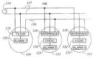
- System 100(shown in FIG. 1A) includes a plurality of devices 109 , 111 , 113 , electrically connected by an interconnect line 116 that enables the devices to communicate digitally with one another.
- System 100includes three interconnect lines, two of which 117 are employed for providing electric power 114 , the other of which is an interconnect line 116 .
- External voltage source 114is typically an alternating current (AC) source at a nominal 115 VAC and 60 Hz frequency. Other combinations of voltage and line frequency may also be employed.
- ACalternating current
- Device 109is representative of any type of device having a simple filter circuit 124 which is connectable through a conventional interconnect port or terminal(s) (not shown) to interconnect line 116 .
- Device 109may include conventional smoke alarms, heat alarms, relay modules, alarm signaling panels, and the like.
- the deviceincludes a sensing circuit portion 126 capable of detecting the particular hazard and triggering an alarm indicator (not shown).
- Devices 111 , 113are representative of any device of the present invention having an interface circuit 118 connectable through a conventional port or terminal(s) (not shown) to interconnect line 116 to communicate digital information.
- Devices 111 , 113may include carbon monoxide (i.e., CO) alarms, motion detectors, smoke alarms, heat alarms, gas alarms, relay modules, alarm signaling panels, door/window open sensors, building security devices in general, and the like. These devices include a sensing circuit portion 123 , 125 , respectively, which is capable of detecting the particular hazard, and triggering a local alarm indicator (not shown).
- the term ‘local’refers to a component disposed integrally within a particular device, as opposed to components disposed within another device.
- Devices 111 , 113may further be of a single type or may be of two or more mutually distinct types of devices.
- device 111may be a CO alarm, while device 113 may be heat alarm.
- Devices 111 , 113may still further include a logic module 120 for modulating the digital information.
- Logic module 120may include any suitable component commonly used for this purpose, including an electronic circuit, a microcontroller, an electronic processor, a programmable logic device, a communications processor, a computer, or combination thereof. The structure and function of interface circuit 118 and logic module 120 are discussed in substantially more detail hereinbelow.
- System 100 ′is substantially similar to that of system 100 , excepting that the plurality of devices 109 , 111 , 113 in system 100 ′ do not rely on an external electric power source. Rather, devices 109 , 111 and 113 function on battery (or some other local source of) electric power.
- System 100 ′includes two connecting lines, a first being interconnect line 116 and a second being a voltage reference 115 (e.g. a ground or neutral wire).
- Interface circuit 118may be configured to function independently of any DC voltage that may be present on interconnect line 116 , (e.g., due to analog communication between devices 109 , 111 , 113 ) and may thus be compatible with either system 100 or system 100 ′, as will be discussed in greater detail hereinbelow.
- Systems 100 and 100 ′generally include a plurality of devices, having at least two types of hazard alarms. Although systems 100 and 100 ′ are shown having three or more devices, the skilled artisan will recognize that this depiction is merely exemplary, to demonstrate the versatility of the present invention. It will be understood that a single device, such as discussed in greater detail hereinbelow, and/or a system including as few as two devices, is within the scope of this invention.
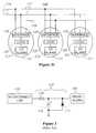
- a combination smoke and carbon monoxide alarm system 200 of the present inventionincludes at least one smoke alarm 209 having a low pass filter circuit 124 , and at least one CO alarm 211 having an interface circuit 118 and a logic module 120 .
- System 200is in many respects substantially similar to system 100 . As stated above, although FIG. 2A shows a system including two smoke alarms and two CO alarms, it is understood that system 200 may include any number of smoke alarms 209 and CO alarms 211 .
- System 200is advantageous in that it enables CO alarms 211 and smoke alarms 209 to share a common interconnect line 116 so that an alarm event detected in one (or more) of the smoke alarm(s) 209 may trigger other smoke alarm indicators (e.g., such as in other interconnected smoke alarms 209 ), but does not trigger any CO alarm indicators (e.g., does not trigger an alarm indicator in any of the CO alarm(s) 211 ).
- an alarm event detected by one (or more) of the CO alarm(s) 211may trigger other CO alarm indicators without triggering smoke alarm indicators (e.g., without triggering alarm indicators in any of the smoke alarm(s) 209 connected thereto).
- Embodiments of the present inventionprovide this desired functionality by sending digital signals along interconnect line 116 .
- CO alarm 211emits a series of digital signals to activate alarm indicators on other interconnected CO alarms 211 .
- Typical smoke alarmsuse a low pass filter 124 on interconnect line 116 , in which a constant direct current (DC) voltage is generally required to activate an alarm indicator on interconnected smoke alarms.
- the digital signalsgenerally do not activate the smoke alarms, and the DC potential applied by the smoke alarms generally does not activate the CO alarms. Therefore, both CO alarms 211 and smoke alarms 209 (and/or other combinations of devices) may use the same interconnect line without generating false or undesired actuation of devices of other types.
- a kitmay be provided that includes at least one alarm 111 , 113 having an interface circuit 118 .
- the kitmay further include multiple alarms 111 , 113 of a plurality of types.
- One exemplary kitincludes at least one carbon monoxide alarm 211 having an interface circuit 118 configured so that an alarm event in one (or more) of the existing smoke alarm(s) 209 does not trigger an alarm indicator in any of the CO alarm(s) 211 .
- an alarm event in one (or more) of the CO alarm(s) 211does not trigger an alarm indicator in any of the smoke alarm(s) 209 .
- interface circuit 118 and filter circuit 124may be combined into a single unit, such as a combination CO/Smoke alarm 215 and/or a modified CO alarm 217 .
- each of these embodimentsmay include a filter 124 to detect whether a smoke alarm condition is being communicated over interconnect line 116 . In the event such a smoke alarm condition is detected, the alarms 215 and/or 217 may trigger a local alarm indicator for a smoke event (if alarms 215 , 217 are equipped to do so).
- alarms 215 or 217may remain silent (or provide no visual indicator) upon receipt of a smoke alarm condition communication in order to give the smoke alarm condition precedence over a CO alarm condition.
- These alarms 215 and 217may both operate in the manner described hereinabove to detect presence of CO and transmit a CO alarm condition signal over line 116 to other interconnected alarm devices.
- combined CO/Smoke alarm 215includes a smoke sensing circuit portion 226 and CO sensing portion 223 .
- alarm 215may uniquely generate either a smoke or a CO alarm indicator, and respectively use both the interface circuit 118 and filter circuit 124 to communicate a smoke and/or CO alarm condition to other interconnected units.
- FIG. 2Ca further alternative embodiment of the present invention, shown as 200 ′′ in FIG. 2C includes only CO alarms 211 connected by interconnect line 116 .
- the interconnect filter 124is representative of an approach commonly used in self-contained residential smoke alarms that employ an interconnect, and is shown for reference only.
- the interconnect filter 124includes a resistor 128 and capacitor 130 that serve as a low-pass filter, i.e., to generally allow only low frequency signals to reach the smoke alarm sensing circuit portion 126 from interconnect line 116 and prevent high frequency transients and 50 or 60 Hz modulation signals (associated with input AC power) from triggering a local alarm indicator.
- a constant voltage signal present on interconnect line 116(such as that generated by a typical smoke alarm upon detection of smoke) charges capacitor 130 through resistor 128 .
- Zener diode 132clamps any inappropriate voltage spikes across the capacitor to a sufficiently low level to help prevent damage to alarm circuit portion 126 .
- the present inventionincludes electronic circuitry (interface circuit 118 ) that enables of a plurality of devices of at least two type hazard alarms to be interconnected without triggering conflicting alarm indicators.
- Interface circuit 118transmits and receives digital pulses on interconnect line 116 and modulates the pulses to communicate information to effectively form a digital network.
- the encoding and decoding of the digital signalsmay be accomplished directly by electronic circuits or by program code associated with a conventional electronic processor.
- Interface circuit 118consumes a minimal amount of power in order to allow battery operation of the alarm and interface circuit.
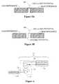
- Interface circuit 118includes three primary portions: (i) an input protection portion 34 , (ii) a high-pass filter portion 36 , and (iii) a signal amplifier portion 38 . Interface circuit 118 is further connected to logic module 120 to transmit and receive digital information to and from interface line 116 , respectively.
- This functionality of logic module 120is provided by a receive logic element 21 and a transmit logic element 22 , which may each include any type of logic element capable of modulating digital information.
- logic module 120may typically be an electronic circuit, a microcontroller, an electronic processor, and/or computer readable program code.
- input protection portion 34includes a metal oxide varistor (MOV) 40 (or an equivalent input protection component such as a zener diode).
- MOV 40provides bipolar voltage protection to capacitor 42 at a level predetermined to substantially prevent damage to the capacitor 42 .
- the resistor 44serves to terminate the interconnect line 116 to help prevent a phenomenon known as ringing on the interconnect line. This may be especially helpful, for example, when only CO alarms are connected to interconnect line 116 , such as shown in FIG. 2C discussed hereinabove. Resistor 44 also partially suppresses any voltages induced on interconnect line 116 by AC voltage on adjacent lines.
- High-pass filter portion 36includes two resistors 50 and 52 , a capacitor 54 , and a transistor 56 .
- This circuitholds the voltage at node 53 at the ground potential except when a high frequency signal or pulse appears at node 51 . Presence of a low frequency signal at node 51 produces a potential across capacitor 54 , which activates transistor 56 . Transistor 56 then shorts node 53 to ground. Conversely, presence of a high frequency signal causes the voltage across capacitor 54 to drop to near zero, thereby deactivating transistor 56 and allowing the signal to appear at node 53 .
- Signal amplifier portion 38includes a DC bypass capacitor 66 , bias resistors 58 and 60 , a low-pass filter resistor 62 and capacitor 68 , and an amplifying transistor 70 and resistor 64 .
- a power supply(not shown) provides a logic level voltage, VCC (or VDD), at node 65 . In the absence of an incoming signal, node 67 is also at VCC (or VDD).
- Bias resistors 58 and 60hold the potential at node 59 (i.e., the bias potential) at a level just below the activation voltage of transistor 70 . This enables a relatively small signal arriving at node 59 to activate transistor 70 .
- the values of bias resistors 58 and 60may be large (e.g.
- Bypass capacitor 66allows the potential at node 59 to be maintained while a different DC potential exists at node 53 .
- a low-pass filter including resistor 62 , capacitor 68 , and transistor 70function substantially similarly to resistor 50 and capacitor 54 , discussed hereinabove, to ground fast transients and undesired high frequency signals, to prevent them from actuating transistor 70 .
- this low-pass filtermay be implemented by omitting capacitor 68 and relying solely on the capacitance inherent in transistor 70 .
- This low-pass filterin combination with high-pass filter element 36 , creates a band-pass filter designed to pass only the signals of desired frequency while filtering out both higher and lower frequency signals.
- An incoming signal(e.g. a pulse) with a frequency in the band pass range described above, actuates transistor 70 , which shorts node 67 to ground (e.g., effectively supplying a logical “0” to logic circuit 120 as discussed in greater detail hereinbelow with respect to receive logic 21 ).
- Transistor 70 and resistor 64effectively function to amplify the relatively small incoming signal appearing at node 59 to a signal of logic level potentials suitable for interface with logic circuit 20 , the two logic level potentials being VCC (or VDD) and ground.
- VCCis typically used to refer to transistor logic voltage values (typically up to about 7 volts) while VDD is typically used to refer to CMOS (complimentary MOS) logic voltage values (typically up to about 9 volts).
- receive logic element 21includes a NAND latch 72 and an electronic processor 74 . It is often desirable in some applications for interface circuit 118 and logic module 120 to be relatively energy efficient (for example in applications in which devices 109 , 111 , and 113 are powered by a battery). Further, when electronic processor 74 is a microcontroller, it may be desirable to put the microcontroller into a low power or ‘sleep’ mode. In this mode, the microcontroller does not generally process actively and most of its circuitry tends to be inactive. A microcontroller may generally be reactivated by an external signal such as that produced by interface circuit 118 .
- the external signalmust generally be maintained for some minimum time period in order for the microcontroller to ‘wake up’ from ‘sleep’ mode and execute the appropriate logic required to respond to the signal.
- the signal generated by interface circuit 118is often of short duration. Therefore, it may be desirable to have an external circuit, such as the NAND latch 72 , that captures the signal for a duration that is long enough to nominally ensure that the microcontroller 74 is properly ‘woken up’. This functionality may be provided in any suitable manner.
- the voltages at nodes 73 , 75 and 76are generally (i.e., in the absence of an incoming signal) at a VCC (or VDD) potential, which corresponds to a logical “1”.
- a ground pulse(logical “0”) may be applied to node 75 by interface circuit 118 (i.e., by node 67 of FIG. 4 ), which in turn produces a ground potential signal (logical “0”) at node 73 .
- the operation of the NAND latch 72serves to maintain this ground potential at 73 even after the signal from the interface circuit 118 at node 75 has returned to a logical “1”, to provide a sufficient “wake-up” signal to the microcontroller 74 .
- the microcontrollerrecognizes the ground signal at node 73 , it applies a ground potential pulse (logical “0”) to the reset line 76 causing the signal at node 73 to return to VCC (or VDD) (logical “1”).
- VCCor VDD
- the microcontroller 74may analyze the incoming digital signal (e.g, pulse train) to determined whether or not to actuate an alarm indicator.
- numerous other means of capturing a short duration signal to provide a microcontroller with sufficient time to process the signalmay be utilized without departing from the spirit and scope of the present invention.
- interface circuit 118may also be utilized to transmit high frequency pulses or signals onto interconnect line 116 . This may be accomplished by applying a high frequency signal from transmit logic element 22 of logic module 120 to node 47 of input protection element 34 .
- the signal transmitted by transmit logic element 22may be of any type that is effectual for communicating digital information.
- Two examples of digital signals that may be effectiveare the voltage pulses shown in FIG. 5 .
- Transmit logic element 22normally holds its output line in a high impedance state in order to have little or no affect on the signals being received by interface circuit 118 .
- transmit logic element 22pushes node 47 to VCC (or VDD) potential for a period of time and then returns the output line back to a high impedance state until such time that it is ready to transmit another pulse.
- VCCor VDD
- transmit logic element 22first pulls node 47 to ground potential for a predetermined period of time and then pushes node 47 to VCC (or VDD) potential for a similar period of time. Transmit logic element 22 then returns the output line back to a high impedance state.
- the duration of the pulsesmay be of any length of time that provides a signal that is recognizable by receive logic element 21 (i.e., element 21 of another interconnected alarm).
- logic module 120 and interface circuit 118may be configured to use a pulse having a duration of less than about 5 milliseconds. In another example, logic module 120 and interface circuit 118 may be configured to use a pulse having a duration from about 2 to about 20 microseconds.
- a pulse sequence(e.g., a pulse train) of predetermined frequency may be used to denote an alarm condition or some other condition that may have only two states.
- the time between pulsesmay be varied such that a relatively short time is assigned one binary value (e.g., a logical 1) and a relatively longer time is assigned another binary value (e.g., a logical 0).
- a series of short and long times between pulsesmay then be used to transmit any manner of information as is common in electronic network communication systems.
- AMIDifferential NRZ, Manchester encoding, or any other form of pulse code modulation may be used without departing from the spirit and scope of the present invention.
- Such digital informationmay be transmitted at a relatively high rate.
- logic module 120 and interface circuit 118may be configured to receive and transmit digital information at a bit rate of greater than about 100 bits per second. In another example, they may be configured to receive and transmit digital information at a bit rate of greater than about 10,000 bits per second.
- the artisan of ordinary skillwill readily recognize that there are numerous means that may be used to modulate the pulses to produce a communication signal according to the present invention.
- interconnect line 116it may be necessary to determine whether the transmitted information has been corrupted by two or more devices sending signals simultaneously (e.g., generating a collision) or by high frequency noise on interconnect line 116 .
- the interval between pulses, in which transmit logic 22 is emitting a high impedance signal,is used to detect this situation.
- the present inventionmay be used to create a peer-to-peer network with collision detection by using techniques well-known to those skilled in the art, such as those commonly used in Ethernet local area networks (LANS). For example, collisions may be indicated when a transmitting device detects extraneous pulses on the interconnect line during transmission of a message.
- LPSEthernet local area networks
- the transmitting device that has detected the collisionmay reinforce the collision by sending a series of pulses causing the other transmitting device or devices to also detect a collision. Each of the transmitting devices may then stop transmitting and attempt to retransmit after a random period of time.
- the alarm systemwas fabricated according to the principles of the present invention in order to evaluate the performance thereof.
- the alarm systemconsisted of thirty-two (32) smoke alarms and two carbon monoxide alarms interconnected together in a three-wire arrangement (similar to that shown in FIG. 1 A).
- the first two lineswere used to provide electrical power (nominally 115VAC at 60 Hz) to the alarm devices.
- the thirdwas used for communicating digital information.
- the 32 smoke alarmswere uniformly distributed along 250 feet of interconnect line, while one carbon monoxide alarm was coupled to each end.
- Each carbon monoxide alarmincluded an interconnect circuit substantially identical to that shown in FIG. 4 . Circuit values for the interconnect circuit used in this example are given in Table 1.
- the interface circuit and logic modulewere configured to transmit logic according to the pulse 90 pattern shown in FIG. 5A at a VDD potential of 9 volts.
- the interface circuit and logic modulewere configure to receive logic at a VCC potential of 3.3 volts.
- the system of this examplewas tested repeatedly without failure. An alarm event was triggered numerous times in each of the smoke alarms. In each instance, each of the 32 smoke alarms sounded an alarm while the carbon monoxide alarms remained silent. Further, alarm events were repeatedly triggered in each of the carbon monoxide alarms (once every four seconds for a duration of 4 hours). In each instance, each of the carbon monoxide alarms sounded an alarm while the smoke alarms remained silent. No failures or false alarms were observed in the testing of this example system.
Landscapes
- Business, Economics & Management (AREA)
- Emergency Management (AREA)
- Physics & Mathematics (AREA)
- General Physics & Mathematics (AREA)
- Fire Alarms (AREA)
- Alarm Systems (AREA)
- Emergency Alarm Devices (AREA)
Abstract
Description
| TABLE 1 | |||
| Figure Notation | Description | Value or | |
| 40 | Metal Oxide Varistor | 47 | |
| 42 | Capacitor | 0.1 μF | |
| 44 | 100 kΩ | ||
| 46 | Zener Diode | 10 | |
| 50 | Resistor | 8.2 kΩ | |
| 52 | Resistor | 560 Ω | |
| 54 | Capacitor | 0.1 μF | |
| 56 | 2N3904 | ||
| 58 | Resistor | 7.5 MΩ | |
| 60 | 1 | ||
| 62 | 100 kΩ | ||
| 64 | 1 | ||
| 66 | 22 | ||
| 68 | 22 | ||
| 70 | NPN Transistor | 2N3904 | |
Claims (61)
Priority Applications (7)
| Application Number | Priority Date | Filing Date | Title |
|---|---|---|---|
| US09/835,685US6611204B2 (en) | 2001-04-16 | 2001-04-16 | Hazard alarm, system, and communication therefor |
| AU21291/02AAU785405B2 (en) | 2001-04-16 | 2002-03-07 | Hazard alarm, system, and communication therefor |
| CA2375021ACA2375021C (en) | 2001-04-16 | 2002-03-08 | Hazard alarm, system, and communication therefor |
| ES02007737TES2279846T3 (en) | 2001-04-16 | 2002-04-05 | COMMUNICATION SYSTEM FOR RISK ALARMS. |
| AT02007737TATE347724T1 (en) | 2001-04-16 | 2002-04-05 | COMMUNICATION SYSTEM FOR HAZARD DETECTORS |
| DE60216536TDE60216536T2 (en) | 2001-04-16 | 2002-04-05 | Communication system for hazard detectors |
| EP02007737AEP1251473B1 (en) | 2001-04-16 | 2002-04-05 | Communication system for hazard alarms |
Applications Claiming Priority (1)
| Application Number | Priority Date | Filing Date | Title |
|---|---|---|---|
| US09/835,685US6611204B2 (en) | 2001-04-16 | 2001-04-16 | Hazard alarm, system, and communication therefor |
Publications (2)
| Publication Number | Publication Date |
|---|---|
| US20020171544A1 US20020171544A1 (en) | 2002-11-21 |
| US6611204B2true US6611204B2 (en) | 2003-08-26 |
Family
ID=25270198
Family Applications (1)
| Application Number | Title | Priority Date | Filing Date |
|---|---|---|---|
| US09/835,685Expired - LifetimeUS6611204B2 (en) | 2001-04-16 | 2001-04-16 | Hazard alarm, system, and communication therefor |
Country Status (6)
| Country | Link |
|---|---|
| US (1) | US6611204B2 (en) |
| EP (1) | EP1251473B1 (en) |
| AT (1) | ATE347724T1 (en) |
| CA (1) | CA2375021C (en) |
| DE (1) | DE60216536T2 (en) |
| ES (1) | ES2279846T3 (en) |
Cited By (38)
| Publication number | Priority date | Publication date | Assignee | Title |
|---|---|---|---|---|
| US20050116819A1 (en)* | 2002-03-26 | 2005-06-02 | Rainer Hoffman | Alarm and control system for a switch cabinet |
| US20060082452A1 (en)* | 2004-10-15 | 2006-04-20 | Ranco Incorporated Of Delaware | Method for initiating a remote hazardous condition detector self test and for testing the interconnection of remote hazardous condition detectors |
| US20060082461A1 (en)* | 2004-10-18 | 2006-04-20 | Walter Kidde Portable Equipment, Inc. | Gateway device to interconnect system including life safety devices |
| US20060082453A1 (en)* | 2004-10-15 | 2006-04-20 | Ranco Incorporated Of Delaware | Method for testing the interconnection of remote hazardous condition detectors |
| US20060092012A1 (en)* | 2004-10-15 | 2006-05-04 | Ranco Incorporated Of Delaware | Circuit and method for prioritization of hazardous condition messages for interconnected hazardous condition detectors |
| US20060145832A1 (en)* | 2004-12-21 | 2006-07-06 | Yossi Bedarshi | Communication system and method |
| US20060226973A1 (en)* | 2005-03-30 | 2006-10-12 | Ranco Incorporated Of Delaware | Device, system, and method for providing hazard warnings |
| US20070279213A1 (en)* | 2006-06-02 | 2007-12-06 | Cartwright Kirby W | Multifunctional relay module for use with CO and smoke alarms |
| US20070290833A1 (en)* | 2006-06-02 | 2007-12-20 | Cartwright Kirby W | Method of selecting operation in a line-powered module |
| US7339468B2 (en) | 2004-10-18 | 2008-03-04 | Walter Kidde Portable Equipment, Inc. | Radio frequency communications scheme in life safety devices |
| US20080291036A1 (en)* | 2007-05-25 | 2008-11-27 | Robert Charles Richmond | Multifunction smoke alarm unit |
| US7508314B2 (en) | 2004-10-18 | 2009-03-24 | Walter Kidde Portable Equipment, Inc. | Low battery warning silencing in life safety devices |
| US20090128353A1 (en)* | 2007-11-20 | 2009-05-21 | Universal Security Instruments, Inc. | Alarm Origination Latching System and Method |
| US20100033319A1 (en)* | 2008-08-08 | 2010-02-11 | Pattok Greg R | Notification system and method thereof |
| US20100271220A1 (en)* | 2009-04-24 | 2010-10-28 | Pattok Greg R | Detection Device System and Device Thereof |
| US20130049951A1 (en)* | 2010-05-14 | 2013-02-28 | Christopher George Kalivas | Fire alarm power line carrier com-system |
| US8659416B1 (en) | 2010-01-14 | 2014-02-25 | Victor M. Higgins | Instrument for detecting and alerting during an emergency situation |
| US20140244714A1 (en)* | 2013-02-25 | 2014-08-28 | Google Inc. | Suppression of Extraneous Alerts on Multiple Devices |
| US8836532B2 (en) | 2009-07-16 | 2014-09-16 | Gentex Corporation | Notification appliance and method thereof |
| US20150077248A1 (en)* | 2013-09-17 | 2015-03-19 | Microchip Technology Incorporated | Smoke Detectors with Wireless Local Area Network Capabilities |
| US20150077242A1 (en)* | 2013-09-17 | 2015-03-19 | Microchip Technology Incorporated | Initiation of Carbon Monoxide and/or Smoke Detector Alarm Test Using Image Recognition and/or Facial Gesturing |
| US9407591B2 (en) | 2013-12-10 | 2016-08-02 | Google Inc. | Predictive forwarding of notification data |
| US9520042B2 (en) | 2013-09-17 | 2016-12-13 | Microchip Technology Incorporated | Smoke detector with enhanced audio and communications capabilities |
| US20190340917A1 (en)* | 2016-06-17 | 2019-11-07 | Utc Fire & Security Emea Bvba | Sensor data transmission system |
| US10957180B2 (en) | 2017-05-12 | 2021-03-23 | Robert Levine | Confined space failsafe access system |
| US11263895B2 (en) | 2017-04-05 | 2022-03-01 | Carrier Corporation | Audio riser active electrical supervision |
| US11328582B1 (en) | 2021-07-07 | 2022-05-10 | T-Mobile Usa, Inc. | Enhanced hazard detection device configured with security and communications capabilities |
| US11636870B2 (en) | 2020-08-20 | 2023-04-25 | Denso International America, Inc. | Smoking cessation systems and methods |
| US11760170B2 (en) | 2020-08-20 | 2023-09-19 | Denso International America, Inc. | Olfaction sensor preservation systems and methods |
| US11760169B2 (en) | 2020-08-20 | 2023-09-19 | Denso International America, Inc. | Particulate control systems and methods for olfaction sensors |
| US11813926B2 (en) | 2020-08-20 | 2023-11-14 | Denso International America, Inc. | Binding agent and olfaction sensor |
| US11828210B2 (en) | 2020-08-20 | 2023-11-28 | Denso International America, Inc. | Diagnostic systems and methods of vehicles using olfaction |
| US11881093B2 (en) | 2020-08-20 | 2024-01-23 | Denso International America, Inc. | Systems and methods for identifying smoking in vehicles |
| US11932080B2 (en) | 2020-08-20 | 2024-03-19 | Denso International America, Inc. | Diagnostic and recirculation control systems and methods |
| US12017506B2 (en) | 2020-08-20 | 2024-06-25 | Denso International America, Inc. | Passenger cabin air control systems and methods |
| US12251991B2 (en) | 2020-08-20 | 2025-03-18 | Denso International America, Inc. | Humidity control for olfaction sensors |
| US12269315B2 (en) | 2020-08-20 | 2025-04-08 | Denso International America, Inc. | Systems and methods for measuring and managing odor brought into rental vehicles |
| US12377711B2 (en) | 2020-08-20 | 2025-08-05 | Denso International America, Inc. | Vehicle feature control systems and methods based on smoking |
Families Citing this family (11)
| Publication number | Priority date | Publication date | Assignee | Title |
|---|---|---|---|---|
| GB2397422A (en)* | 2003-01-18 | 2004-07-21 | Diana Burlington | Portable warning device |
| EP1906371B1 (en)* | 2006-09-28 | 2011-10-19 | E.I. Technology Limited | Control of alarm devices |
| US7706493B2 (en)* | 2006-11-09 | 2010-04-27 | Lennox Industries Inc. | System and method of transmitting data within a three-wire network |
| US8704654B1 (en)* | 2007-06-07 | 2014-04-22 | The United States Of America As Represented By The Administrator Of National Aeronautics And Space Administration | Circuit for communication over DC power line using high temperature electronics |
| US8049613B2 (en)* | 2008-11-26 | 2011-11-01 | Comcast Cable Holdings, Llc | Building security system |
| US9449504B2 (en) | 2013-03-21 | 2016-09-20 | Microsoft Technology Licensing, Llc | Code sequence control of infrared blaster |
| US9552711B2 (en) | 2014-07-18 | 2017-01-24 | Google Inc. | Systems and methods for intelligent alarming |
| US10340687B2 (en)* | 2016-03-07 | 2019-07-02 | Texas Instruments Incorporated | ESD protection circuit and method with high immunity to hot plug insertion and other transient events |
| CN107025749A (en)* | 2017-04-25 | 2017-08-08 | 深圳市创享联盟科技有限公司 | Outdoor enclosure anti-theft alarming equipment and outdoor enclosure anti-theft alarming method |
| CN108398902A (en)* | 2018-03-05 | 2018-08-14 | 哈工大机器人(合肥)国际创新研究院 | A kind of kitchen safety monitoring system and method based on FPGA |
| US11193918B2 (en)* | 2019-11-05 | 2021-12-07 | Michelle Brown | Vehicular carbon monoxide alarm |
Citations (26)
| Publication number | Priority date | Publication date | Assignee | Title |
|---|---|---|---|---|
| US3978476A (en) | 1973-12-17 | 1976-08-31 | Hochiki Corporation | Circuit conduction test arrangement for emergency alarm systems |
| US4091363A (en) | 1977-01-03 | 1978-05-23 | Pittway Corporation | Self-contained fire detector with interconnection circuitry |
| US4207558A (en) | 1978-04-03 | 1980-06-10 | Pittway Corporation | Interconnection circuit for a plurality of alarm units |
| US4223303A (en) | 1978-12-11 | 1980-09-16 | General Electric Company | Alarm devices for interconnected multi-device systems |
| US4282519A (en) | 1977-10-06 | 1981-08-04 | Honeywell Inc. | Interconnection of alarms of smoke detectors with distinguishable alarms |
| US4375637A (en) | 1981-02-24 | 1983-03-01 | Firecom, Inc. | Integrated alarm, security, building management, and communications system |
| US4468664A (en) | 1980-05-21 | 1984-08-28 | American District Telegraph Company | Non-home run zoning system |
| US4578669A (en) | 1983-09-12 | 1986-03-25 | Hydril Company | Remote switch position indicator |
| US4586040A (en) | 1982-05-15 | 1986-04-29 | Matsushita Electric Works, Ltd. | Interruption handling system in time division multiplex remote control system |
| US4600914A (en) | 1983-02-10 | 1986-07-15 | Walsh James W | Apparatus for directing attention to specific locations such as emergency exits |
| US4613848A (en) | 1984-11-29 | 1986-09-23 | Teletron Security, Inc. | Multiple-zone intrusion detection system |
| US4618853A (en) | 1984-03-05 | 1986-10-21 | Hochiki Corporation | Fire detector |
| US4641322A (en) | 1983-10-18 | 1987-02-03 | Nec Corporation | System for carrying out spread spectrum communication through an electric power line |
| US4651036A (en) | 1984-02-24 | 1987-03-17 | Societe Pour L'etude Et La Fabrication De Circuits Integres Speciaux | Logic data transfer bus preloading circuit |
| US4692750A (en) | 1986-03-31 | 1987-09-08 | Matsushita Electric Works, Ltd. | Fire alarm system |
| US4777473A (en) | 1986-08-22 | 1988-10-11 | Fire Burglary Instruments, Inc. | Alarm system incorporating dynamic range testing |
| US4796025A (en) | 1985-06-04 | 1989-01-03 | Simplex Time Recorder Co. | Monitor/control communication net with intelligent peripherals |
| US4916432A (en) | 1987-10-21 | 1990-04-10 | Pittway Corporation | Smoke and fire detection system communication |
| US4977527A (en) | 1988-04-14 | 1990-12-11 | Fike Corporation | Threshold compensation and calibration in distributed environmental detection system for fire detection and suppression |
| US5686896A (en) | 1995-09-28 | 1997-11-11 | Interactive Technologies, Inc. | Low battery report inhibitor for a sensor |
| US5705979A (en) | 1995-04-13 | 1998-01-06 | Tropaion Inc. | Smoke detector/alarm panel interface unit |
| US5786767A (en) | 1997-04-29 | 1998-07-28 | Severino; Joseph | Home safety system |
| US5864286A (en) | 1995-05-16 | 1999-01-26 | General Signal Corporation | Distributed intelligence alarm system having a two- tier monitoring process for detecting alarm conditions |
| US5917405A (en)* | 1993-06-08 | 1999-06-29 | Joao; Raymond Anthony | Control apparatus and methods for vehicles |
| US5933078A (en) | 1997-07-29 | 1999-08-03 | Ranco Inc. Of Delaware | Multi-station dangerous condition alarm system incorporating alarm and chirp origination feature |
| US5966079A (en) | 1997-02-19 | 1999-10-12 | Ranco Inc. Of Delaware | Visual indicator for identifying which of a plurality of dangerous condition warning devices has issued an audible low battery warning signal |
Family Cites Families (4)
| Publication number | Priority date | Publication date | Assignee | Title |
|---|---|---|---|---|
| EP0102229B1 (en)* | 1982-08-27 | 1987-03-18 | Monicell Limited | Alarm system |
| EP0147385B1 (en)* | 1982-11-26 | 1988-04-20 | Hans Gunnar Holmgren | A locality supervision system |
| GB2220779A (en)* | 1988-06-30 | 1990-01-17 | Quebec Inc 2625 4219 | Automated neighboorhood security system |
| US6184787B1 (en)* | 1998-06-04 | 2001-02-06 | Duane A. Morris | Overhead garage door position monitoring system |
- 2001
- 2001-04-16USUS09/835,685patent/US6611204B2/ennot_activeExpired - Lifetime
- 2002
- 2002-03-08CACA2375021Apatent/CA2375021C/ennot_activeExpired - Fee Related
- 2002-04-05ESES02007737Tpatent/ES2279846T3/ennot_activeExpired - Lifetime
- 2002-04-05ATAT02007737Tpatent/ATE347724T1/ennot_activeIP Right Cessation
- 2002-04-05DEDE60216536Tpatent/DE60216536T2/ennot_activeExpired - Fee Related
- 2002-04-05EPEP02007737Apatent/EP1251473B1/ennot_activeExpired - Lifetime
Patent Citations (26)
| Publication number | Priority date | Publication date | Assignee | Title |
|---|---|---|---|---|
| US3978476A (en) | 1973-12-17 | 1976-08-31 | Hochiki Corporation | Circuit conduction test arrangement for emergency alarm systems |
| US4091363A (en) | 1977-01-03 | 1978-05-23 | Pittway Corporation | Self-contained fire detector with interconnection circuitry |
| US4282519A (en) | 1977-10-06 | 1981-08-04 | Honeywell Inc. | Interconnection of alarms of smoke detectors with distinguishable alarms |
| US4207558A (en) | 1978-04-03 | 1980-06-10 | Pittway Corporation | Interconnection circuit for a plurality of alarm units |
| US4223303A (en) | 1978-12-11 | 1980-09-16 | General Electric Company | Alarm devices for interconnected multi-device systems |
| US4468664A (en) | 1980-05-21 | 1984-08-28 | American District Telegraph Company | Non-home run zoning system |
| US4375637A (en) | 1981-02-24 | 1983-03-01 | Firecom, Inc. | Integrated alarm, security, building management, and communications system |
| US4586040A (en) | 1982-05-15 | 1986-04-29 | Matsushita Electric Works, Ltd. | Interruption handling system in time division multiplex remote control system |
| US4600914A (en) | 1983-02-10 | 1986-07-15 | Walsh James W | Apparatus for directing attention to specific locations such as emergency exits |
| US4578669A (en) | 1983-09-12 | 1986-03-25 | Hydril Company | Remote switch position indicator |
| US4641322A (en) | 1983-10-18 | 1987-02-03 | Nec Corporation | System for carrying out spread spectrum communication through an electric power line |
| US4651036A (en) | 1984-02-24 | 1987-03-17 | Societe Pour L'etude Et La Fabrication De Circuits Integres Speciaux | Logic data transfer bus preloading circuit |
| US4618853A (en) | 1984-03-05 | 1986-10-21 | Hochiki Corporation | Fire detector |
| US4613848A (en) | 1984-11-29 | 1986-09-23 | Teletron Security, Inc. | Multiple-zone intrusion detection system |
| US4796025A (en) | 1985-06-04 | 1989-01-03 | Simplex Time Recorder Co. | Monitor/control communication net with intelligent peripherals |
| US4692750A (en) | 1986-03-31 | 1987-09-08 | Matsushita Electric Works, Ltd. | Fire alarm system |
| US4777473A (en) | 1986-08-22 | 1988-10-11 | Fire Burglary Instruments, Inc. | Alarm system incorporating dynamic range testing |
| US4916432A (en) | 1987-10-21 | 1990-04-10 | Pittway Corporation | Smoke and fire detection system communication |
| US4977527A (en) | 1988-04-14 | 1990-12-11 | Fike Corporation | Threshold compensation and calibration in distributed environmental detection system for fire detection and suppression |
| US5917405A (en)* | 1993-06-08 | 1999-06-29 | Joao; Raymond Anthony | Control apparatus and methods for vehicles |
| US5705979A (en) | 1995-04-13 | 1998-01-06 | Tropaion Inc. | Smoke detector/alarm panel interface unit |
| US5864286A (en) | 1995-05-16 | 1999-01-26 | General Signal Corporation | Distributed intelligence alarm system having a two- tier monitoring process for detecting alarm conditions |
| US5686896A (en) | 1995-09-28 | 1997-11-11 | Interactive Technologies, Inc. | Low battery report inhibitor for a sensor |
| US5966079A (en) | 1997-02-19 | 1999-10-12 | Ranco Inc. Of Delaware | Visual indicator for identifying which of a plurality of dangerous condition warning devices has issued an audible low battery warning signal |
| US5786767A (en) | 1997-04-29 | 1998-07-28 | Severino; Joseph | Home safety system |
| US5933078A (en) | 1997-07-29 | 1999-08-03 | Ranco Inc. Of Delaware | Multi-station dangerous condition alarm system incorporating alarm and chirp origination feature |
Cited By (57)
| Publication number | Priority date | Publication date | Assignee | Title |
|---|---|---|---|---|
| US7233244B2 (en)* | 2002-03-26 | 2007-06-19 | Emka Beschlagteile Gmbh & Co. Kg | Alarm and control system for a switch cabinet |
| US20050116819A1 (en)* | 2002-03-26 | 2005-06-02 | Rainer Hoffman | Alarm and control system for a switch cabinet |
| US20060082452A1 (en)* | 2004-10-15 | 2006-04-20 | Ranco Incorporated Of Delaware | Method for initiating a remote hazardous condition detector self test and for testing the interconnection of remote hazardous condition detectors |
| US20060082453A1 (en)* | 2004-10-15 | 2006-04-20 | Ranco Incorporated Of Delaware | Method for testing the interconnection of remote hazardous condition detectors |
| US20060092012A1 (en)* | 2004-10-15 | 2006-05-04 | Ranco Incorporated Of Delaware | Circuit and method for prioritization of hazardous condition messages for interconnected hazardous condition detectors |
| US7126487B2 (en) | 2004-10-15 | 2006-10-24 | Ranco Incorporated Of Delaware | Circuit and method for prioritization of hazardous condition messages for interconnected hazardous condition detectors |
| US7158023B2 (en) | 2004-10-15 | 2007-01-02 | Ranco Incorporated Of Delaware | Method for testing the interconnection of remote hazardous condition detectors |
| US7242288B2 (en) | 2004-10-15 | 2007-07-10 | Ranco Incorporated Of Delaware | Method for initiating a remote hazardous condition detector self test and for testing the interconnection of remote hazardous condition detectors |
| US20060082461A1 (en)* | 2004-10-18 | 2006-04-20 | Walter Kidde Portable Equipment, Inc. | Gateway device to interconnect system including life safety devices |
| US7339468B2 (en) | 2004-10-18 | 2008-03-04 | Walter Kidde Portable Equipment, Inc. | Radio frequency communications scheme in life safety devices |
| US7508314B2 (en) | 2004-10-18 | 2009-03-24 | Walter Kidde Portable Equipment, Inc. | Low battery warning silencing in life safety devices |
| US7385517B2 (en) | 2004-10-18 | 2008-06-10 | Walter Kidde Portable Equipment, Inc. | Gateway device to interconnect system including life safety devices |
| US20060145832A1 (en)* | 2004-12-21 | 2006-07-06 | Yossi Bedarshi | Communication system and method |
| US20060226973A1 (en)* | 2005-03-30 | 2006-10-12 | Ranco Incorporated Of Delaware | Device, system, and method for providing hazard warnings |
| US7423544B2 (en) | 2006-06-02 | 2008-09-09 | Ranco Incorporated Of Delaware | Method of selecting operation in a line-powered module |
| US7423543B2 (en) | 2006-06-02 | 2008-09-09 | Maple Chase Company | Multifunctional relay module for use with CO and smoke alarms |
| US20070279213A1 (en)* | 2006-06-02 | 2007-12-06 | Cartwright Kirby W | Multifunctional relay module for use with CO and smoke alarms |
| US20070290833A1 (en)* | 2006-06-02 | 2007-12-20 | Cartwright Kirby W | Method of selecting operation in a line-powered module |
| US20080291036A1 (en)* | 2007-05-25 | 2008-11-27 | Robert Charles Richmond | Multifunction smoke alarm unit |
| US7994928B2 (en)* | 2007-05-25 | 2011-08-09 | Robert Charles Richmond | Multifunction smoke alarm unit |
| US7893825B2 (en) | 2007-11-20 | 2011-02-22 | Universal Security Instruments, Inc. | Alarm origination latching system and method |
| US20090128353A1 (en)* | 2007-11-20 | 2009-05-21 | Universal Security Instruments, Inc. | Alarm Origination Latching System and Method |
| US20100033319A1 (en)* | 2008-08-08 | 2010-02-11 | Pattok Greg R | Notification system and method thereof |
| US7920053B2 (en) | 2008-08-08 | 2011-04-05 | Gentex Corporation | Notification system and method thereof |
| US20100271220A1 (en)* | 2009-04-24 | 2010-10-28 | Pattok Greg R | Detection Device System and Device Thereof |
| US8232884B2 (en) | 2009-04-24 | 2012-07-31 | Gentex Corporation | Carbon monoxide and smoke detectors having distinct alarm indications and a test button that indicates improper operation |
| US8836532B2 (en) | 2009-07-16 | 2014-09-16 | Gentex Corporation | Notification appliance and method thereof |
| US8659416B1 (en) | 2010-01-14 | 2014-02-25 | Victor M. Higgins | Instrument for detecting and alerting during an emergency situation |
| US9443416B2 (en) | 2010-05-14 | 2016-09-13 | Chris Kalivas | Fire alarm power line carrier com-system |
| US20130049951A1 (en)* | 2010-05-14 | 2013-02-28 | Christopher George Kalivas | Fire alarm power line carrier com-system |
| US8878665B2 (en)* | 2010-05-14 | 2014-11-04 | Christopher George Kalivas | Fire alarm power line carrier com-system |
| US20140244714A1 (en)* | 2013-02-25 | 2014-08-28 | Google Inc. | Suppression of Extraneous Alerts on Multiple Devices |
| US9503409B2 (en)* | 2013-02-25 | 2016-11-22 | Google Inc. | Suppression of extraneous alerts on multiple devices |
| US20150077242A1 (en)* | 2013-09-17 | 2015-03-19 | Microchip Technology Incorporated | Initiation of Carbon Monoxide and/or Smoke Detector Alarm Test Using Image Recognition and/or Facial Gesturing |
| US9159218B2 (en)* | 2013-09-17 | 2015-10-13 | Microchip Technology Incorporated | Initiation of carbon monoxide and/or smoke detector alarm test using image recognition and/or facial gesturing |
| US9520042B2 (en) | 2013-09-17 | 2016-12-13 | Microchip Technology Incorporated | Smoke detector with enhanced audio and communications capabilities |
| US20150077248A1 (en)* | 2013-09-17 | 2015-03-19 | Microchip Technology Incorporated | Smoke Detectors with Wireless Local Area Network Capabilities |
| US9407591B2 (en) | 2013-12-10 | 2016-08-02 | Google Inc. | Predictive forwarding of notification data |
| US9853931B2 (en) | 2013-12-10 | 2017-12-26 | Google Llc | Predictive forwarding of notification data |
| US10469430B2 (en) | 2013-12-10 | 2019-11-05 | Google Llc | Predictive forwarding of notification data |
| US20190340917A1 (en)* | 2016-06-17 | 2019-11-07 | Utc Fire & Security Emea Bvba | Sensor data transmission system |
| US10769936B2 (en)* | 2016-06-17 | 2020-09-08 | Utc Fire & Security Emea Bvba | Sensor data transmission system |
| US11545026B2 (en) | 2017-04-05 | 2023-01-03 | Carrier Corporation | Audio riser active electrical supervision |
| US11263895B2 (en) | 2017-04-05 | 2022-03-01 | Carrier Corporation | Audio riser active electrical supervision |
| US10957180B2 (en) | 2017-05-12 | 2021-03-23 | Robert Levine | Confined space failsafe access system |
| US11636870B2 (en) | 2020-08-20 | 2023-04-25 | Denso International America, Inc. | Smoking cessation systems and methods |
| US11760170B2 (en) | 2020-08-20 | 2023-09-19 | Denso International America, Inc. | Olfaction sensor preservation systems and methods |
| US11760169B2 (en) | 2020-08-20 | 2023-09-19 | Denso International America, Inc. | Particulate control systems and methods for olfaction sensors |
| US11813926B2 (en) | 2020-08-20 | 2023-11-14 | Denso International America, Inc. | Binding agent and olfaction sensor |
| US11828210B2 (en) | 2020-08-20 | 2023-11-28 | Denso International America, Inc. | Diagnostic systems and methods of vehicles using olfaction |
| US11881093B2 (en) | 2020-08-20 | 2024-01-23 | Denso International America, Inc. | Systems and methods for identifying smoking in vehicles |
| US11932080B2 (en) | 2020-08-20 | 2024-03-19 | Denso International America, Inc. | Diagnostic and recirculation control systems and methods |
| US12017506B2 (en) | 2020-08-20 | 2024-06-25 | Denso International America, Inc. | Passenger cabin air control systems and methods |
| US12251991B2 (en) | 2020-08-20 | 2025-03-18 | Denso International America, Inc. | Humidity control for olfaction sensors |
| US12269315B2 (en) | 2020-08-20 | 2025-04-08 | Denso International America, Inc. | Systems and methods for measuring and managing odor brought into rental vehicles |
| US12377711B2 (en) | 2020-08-20 | 2025-08-05 | Denso International America, Inc. | Vehicle feature control systems and methods based on smoking |
| US11328582B1 (en) | 2021-07-07 | 2022-05-10 | T-Mobile Usa, Inc. | Enhanced hazard detection device configured with security and communications capabilities |
Also Published As
| Publication number | Publication date |
|---|---|
| EP1251473A3 (en) | 2003-07-16 |
| CA2375021A1 (en) | 2002-10-16 |
| DE60216536D1 (en) | 2007-01-18 |
| US20020171544A1 (en) | 2002-11-21 |
| CA2375021C (en) | 2012-02-21 |
| DE60216536T2 (en) | 2007-09-20 |
| EP1251473B1 (en) | 2006-12-06 |
| ATE347724T1 (en) | 2006-12-15 |
| AU2129102A (en) | 2002-10-17 |
| EP1251473A2 (en) | 2002-10-23 |
| ES2279846T3 (en) | 2007-09-01 |
Similar Documents
| Publication | Publication Date | Title |
|---|---|---|
| US6611204B2 (en) | Hazard alarm, system, and communication therefor | |
| US4926162A (en) | High security communication line monitor | |
| US7535687B2 (en) | Alarm system sensor topology apparatus and method | |
| US3886534A (en) | Security system | |
| US20130154823A1 (en) | Alarm Detection and Notification System | |
| EP1184825B1 (en) | Interconnectable detector with local alarm indicator | |
| WO2007121162A1 (en) | Alarm system sensor topology apparatus and method | |
| US5109216A (en) | Portable intrusion alarm | |
| US5459450A (en) | Presence-detecting system | |
| JP2002024953A (en) | Line disconnection and fire occurrence monitoring device, fire alarm device having the same, and line disconnection and fire occurrence monitoring method | |
| US6133828A (en) | Fire detection and alarm system with selective fire warning | |
| JPS61100893A (en) | Residence monitor | |
| US6424257B1 (en) | Bidirectional communication between control element and electrical devices | |
| CA2528873C (en) | Bidirectional communication between control element and electrical devices | |
| JPH0353347Y2 (en) | ||
| KR100226317B1 (en) | Automated guided information transmitter-receiver | |
| JPH01287799A (en) | fire alarm device | |
| Akpiri et al. | Design and Construction of a Comprehensive Digital Security System | |
| JP3380608B2 (en) | Security system | |
| KR200266115Y1 (en) | Detecting Apparatus unifying alarm module | |
| KR800000399B1 (en) | Emergency alarm control system | |
| KR200360317Y1 (en) | Security system using window configuration | |
| KR960008834Y1 (en) | Battery alarm circuit of safety system | |
| JPS5981793A (en) | Alarm equipment reception response device | |
| JPH0379758B2 (en) |
Legal Events
| Date | Code | Title | Description |
|---|---|---|---|
| AS | Assignment | Owner name:MAPLE CHASE COMPANY, ILLINOIS Free format text:ASSIGNMENT OF ASSIGNORS INTEREST;ASSIGNOR:SCHMURR, RANDOL M.;REEL/FRAME:011735/0100 Effective date:20010411 | |
| STCF | Information on status: patent grant | Free format text:PATENTED CASE | |
| AS | Assignment | Owner name:DEUTSCHE BANK AG, LONDON BRANCH,UNITED KINGDOM Free format text:SECURITY AGREEMENT;ASSIGNOR:MAPLE CHASE COMPANY;REEL/FRAME:017921/0822 Effective date:20060713 Owner name:DEUTSCHE BANK AG, LONDON BRANCH, UNITED KINGDOM Free format text:SECURITY AGREEMENT;ASSIGNOR:MAPLE CHASE COMPANY;REEL/FRAME:017921/0822 Effective date:20060713 | |
| AS | Assignment | Owner name:MAPLE CHASE COMPANY, ILLINOIS Free format text:RELEASE AND TERMINATION OF SECURITY INTEREST;ASSIGNOR:DEUTSCHE BANK AG, LONDON BRANCH;REEL/FRAME:018047/0462 Effective date:20060713 | |
| FPAY | Fee payment | Year of fee payment:4 | |
| FPAY | Fee payment | Year of fee payment:8 | |
| FPAY | Fee payment | Year of fee payment:12 |