US6610198B1 - Liquid filter with change interval indicator - Google Patents
Liquid filter with change interval indicatorDownload PDFInfo
- Publication number
- US6610198B1 US6610198B1US09/934,576US93457601AUS6610198B1US 6610198 B1US6610198 B1US 6610198B1US 93457601 AUS93457601 AUS 93457601AUS 6610198 B1US6610198 B1US 6610198B1
- Authority
- US
- United States
- Prior art keywords
- annular space
- filter element
- sleeve
- liquid
- button
- Prior art date
- Legal status (The legal status is an assumption and is not a legal conclusion. Google has not performed a legal analysis and makes no representation as to the accuracy of the status listed.)
- Expired - Lifetime
Links
Images


Classifications
- B—PERFORMING OPERATIONS; TRANSPORTING
- B01—PHYSICAL OR CHEMICAL PROCESSES OR APPARATUS IN GENERAL
- B01D—SEPARATION
- B01D35/00—Filtering devices having features not specifically covered by groups B01D24/00 - B01D33/00, or for applications not specifically covered by groups B01D24/00 - B01D33/00; Auxiliary devices for filtration; Filter housing constructions
- B01D35/14—Safety devices specially adapted for filtration; Devices for indicating clogging
- B01D35/143—Filter condition indicators
- B—PERFORMING OPERATIONS; TRANSPORTING
- B01—PHYSICAL OR CHEMICAL PROCESSES OR APPARATUS IN GENERAL
- B01D—SEPARATION
- B01D36/00—Filter circuits or combinations of filters with other separating devices
- B01D36/001—Filters in combination with devices for the removal of gas, air purge systems
- B—PERFORMING OPERATIONS; TRANSPORTING
- B01—PHYSICAL OR CHEMICAL PROCESSES OR APPARATUS IN GENERAL
- B01D—SEPARATION
- B01D36/00—Filter circuits or combinations of filters with other separating devices
- B01D36/003—Filters in combination with devices for the removal of liquids
Definitions
- the inventionrelates to liquid filters, and more particularly to a service interval change indicator more accurately reflecting filter life.
- Liquid filterstypically have a vertically axially extending housing having an annular filter element extending axially between top and bottom ends and having an inner hollow interior and an outer annular space between the filter element and the housing.
- the housinghas an inlet to the annular space, and an outlet from the hollow interior. Liquid is filtered by flowing from the annular space through the filter element into the hollow interior.
- the annular spaceis viewable through the housing, e.g. through a transparent housing side wall, such that an operator or service technician can see the level of liquid in the annular space as an indication of when to replace the filter element. The higher the level of liquid in the annular space the greater the pressure drop across the filter element and hence the greater the plugging of the filter element.
- the liquid or fuel leveldoes not accurately reflect filter life.
- fuel level in a clear housingreaches the top with 2′′ Mercury, Hg, restriction, while the filter element is capable of 8′′ Mercury, Hg, restriction.
- using fuel level in the noted annular space of the clear housing as an indicator to change the filter elementresults in a premature such change. This is objectionable because of the less than full life usage of the filter element, the more frequent filter element changes, and the corresponding higher overall cost thereof.
- the present inventionaddresses and solves the above noted objections.
- the inventiondelays the rise in liquid level in the noted annular space to correct the otherwise premature indication of a need to change the filter element.
- liquid level in the noted annular spaceis allowed to rise to controlled levels providing advance and more accurate indication of a forthcoming need to change the filter element.
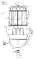
- FIG. 1is a side elevation view of a liquid filter known in the prior art.
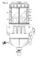
- FIG. 2is a sectional view taken along line 2 — 2 of FIG. 1 .
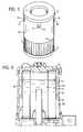
- FIG. 3is a perspective view of a filter element in accordance with the invention.
- FIG. 4is a view like FIG. 1 but incorporating the filter element of the present invention.
- FIG. 5is a view like FIG. 3 and shows a further embodiment.
- FIG. 6is a view like FIG. 2 but incorporating the filter element of FIG. 5 .
- FIG. 7is like FIG. 6 and shows a further stage of operation.
- FIG. 8is like FIG. 5 and shows a further embodiment.
- FIG. 1shows a liquid filter 10 , for example a diesel fuel filter, known in the prior art.
- the filterincludes a housing 12 extending along a generally vertical axis 14 and having an annular filter element 16 extending axially between top and bottom ends 18 and 20 at respective upper and lower end caps 19 and 21 , FIG. 2, and having an inner hollow interior 22 , FIG. 2, and an outer annular space 24 between filter element 16 and side wall 26 of housing 12 .
- the housinghas a lower inlet 28 , FIG. 2, to annular space 24 , and a lower outlet 30 from hollow interior 22 through outlet tube 32 .
- the housingmay include a lower collection bowl or reservoir 34 for collecting coalesced separated water or contaminants for drainage at drain outlet 35 as controlled by valve 36 , and may have an electrical connection 38 for an internal heater, and so on, as is known.
- Housing 12includes the noted cylindrical sidewall 26 closed at its top end by upper end cap 40 in threaded relation, and closed at its bottom end at housing base 42 in threaded relation.
- Sidewall 26is clear or transparent, and hence annular space 24 is viewable through the housing such that an operator or service technician can see the level of liquid such as 44 , FIG. 1, in annular space 24 .
- the operator or service techniciancan see such level and the change thereof as an indication of when to replace filter element 16 .
- the higher the level of liquid in annular space 24the greater the pressure drop across filter element 16 and hence the greater the plugging of filter element 16 .
- it has been found in numerous applications that such liquid level rise from 44 to 46does not correspond to expired filter life. Hence, the filter element is being changed prematurely, and has a longer life than otherwise indicated by the noted rising liquid level in annular space 24 .
- FIGS. 3-8illustrate the present invention and use like reference numerals from above where appropriate to facilitate understanding.
- the inventionis illustrated in the context of the above noted known diesel fuel filter, though the invention is not limited thereto.
- the present inventiondelays the rise of fluid level in annular space 24 for applications where filter element 16 is otherwise changed prematurely and has a longer life than otherwise indicated by the noted rising liquid level in annular space 24 .
- the liquidgives off vapor in the housing, including in annular space 24 .
- This aspectis utilized in the present invention.
- the noted delayis provided by a delay member in the form of a vapor and liquid impermeable sleeve 50 around filter element 16 and having a top end 52 at the top end of the filter element and having a bottom end 54 spaced from the bottom end of the filter element by an axial gap 56 .
- the sleevehas an outer face 58 , FIGS. 4, 6 , facing annular space 24 , and an inner face 60 facing filter element 16 .
- vapor above level 62can no longer flow through axial gap 56 and is trapped in annular space 24 above bottom end 54 of sleeve 50 due to the vapor impermeability of sleeve 50 .
- Further rise of liquid level in annular space 24must compress trapped vapor therein, thus slowing and delaying the rise of liquid level in annular space 24 .
- sleeve 50has one or more apertures therein such as 70 , 72 , 74 , etc. at respective given locations therealong, each having a respective liquid-soluble button 76 , 78 , 80 , respectively, for example a fuel-soluble button made of polyisobutylene, for example available from Lubrizol under Part Number OS158536.
- the buttoninitially closes the respective aperture, and then is dissolved after a given time by contact with the liquid flowing along inner face 60 of sleeve 50 , such that vapor in annular space 24 may pass through the aperture vacated by the button, FIG. 6, whereafter the liquid level rises in annular space 24 from level 62 , FIG. 6, to level 82 , FIG.
- the noted given timeis preferably selected to be the filter element change interval, e.g. by matching dissolution rate of the material and/or thickness to the desired interval.
- sleeve 50has a further plurality of apertures such as 90 , 92 each filled with a respective liquid-soluble button 94 , 96 and axially spaced from bottom end 54 of sleeve 50 by differing axial spacings.
- Buttons 96 , 94 , 78have differing dissolution rates, e.g. by differing thicknesses and/or differing material selection.
- a first of the buttons such as 96 closest to bottom end 54 of sleeve 50has the fastest dissolution rate and dissolves first such that liquid level in annular space 24 rises to a respective first aperture 92 vacated by first button 96 . This provides a first advance indication of a forthcoming need for a filter element change.
- buttons such as 94is spaced axially farther from bottom end 54 of sleeve 50 than first button 96 and has a slower dissolution rate and dissolves second such that the liquid level in annular space 24 further rises to a respective second aperture 90 vacated by second button 94 . This provides a second sequential indication of an oncoming need for a filter element change.
- annularincludes other closed-loop configurations, such as ovals, racetracks, etc.
Landscapes
- Chemical & Material Sciences (AREA)
- Chemical Kinetics & Catalysis (AREA)
- Filtration Of Liquid (AREA)
Abstract
Description
The invention relates to liquid filters, and more particularly to a service interval change indicator more accurately reflecting filter life.
Liquid filters, including fuel filters, typically have a vertically axially extending housing having an annular filter element extending axially between top and bottom ends and having an inner hollow interior and an outer annular space between the filter element and the housing. The housing has an inlet to the annular space, and an outlet from the hollow interior. Liquid is filtered by flowing from the annular space through the filter element into the hollow interior. The annular space is viewable through the housing, e.g. through a transparent housing side wall, such that an operator or service technician can see the level of liquid in the annular space as an indication of when to replace the filter element. The higher the level of liquid in the annular space the greater the pressure drop across the filter element and hence the greater the plugging of the filter element.
In many applications, the liquid or fuel level, including the rise thereof in the noted annular space, does not accurately reflect filter life. For example, in one application, fuel level in a clear housing reaches the top with 2″ Mercury, Hg, restriction, while the filter element is capable of 8″ Mercury, Hg, restriction. Hence, using fuel level in the noted annular space of the clear housing as an indicator to change the filter element results in a premature such change. This is objectionable because of the less than full life usage of the filter element, the more frequent filter element changes, and the corresponding higher overall cost thereof.
The present invention addresses and solves the above noted objections. In one aspect, the invention delays the rise in liquid level in the noted annular space to correct the otherwise premature indication of a need to change the filter element. In another aspect, liquid level in the noted annular space is allowed to rise to controlled levels providing advance and more accurate indication of a forthcoming need to change the filter element.
FIG. 1 is a side elevation view of a liquid filter known in the prior art.
FIG. 2 is a sectional view taken along line2—2 of FIG.1.
FIG. 3 is a perspective view of a filter element in accordance with the invention.
FIG. 4 is a view like FIG. 1 but incorporating the filter element of the present invention.
FIG. 5 is a view like FIG.3 and shows a further embodiment.
FIG. 6 is a view like FIG. 2 but incorporating the filter element of FIG.5.
FIG. 7 is like FIG.6 and shows a further stage of operation.
FIG. 8 is like FIG.5 and shows a further embodiment.
FIG. 1 shows aliquid filter 10, for example a diesel fuel filter, known in the prior art. The filter includes ahousing 12 extending along a generallyvertical axis 14 and having anannular filter element 16 extending axially between top andbottom ends lower end caps annular space 24 betweenfilter element 16 andside wall 26 ofhousing 12. The housing has alower inlet 28, FIG. 2, toannular space 24, and alower outlet 30 from hollow interior22 throughoutlet tube 32. In the case of a diesel fuel filter, the housing may include a lower collection bowl orreservoir 34 for collecting coalesced separated water or contaminants for drainage atdrain outlet 35 as controlled byvalve 36, and may have anelectrical connection 38 for an internal heater, and so on, as is known.
FIGS. 3-8 illustrate the present invention and use like reference numerals from above where appropriate to facilitate understanding. The invention is illustrated in the context of the above noted known diesel fuel filter, though the invention is not limited thereto.
The present invention delays the rise of fluid level inannular space 24 for applications wherefilter element 16 is otherwise changed prematurely and has a longer life than otherwise indicated by the noted rising liquid level inannular space 24. The liquid gives off vapor in the housing, including inannular space 24. This aspect is utilized in the present invention. The noted delay is provided by a delay member in the form of a vapor and liquidimpermeable sleeve 50 aroundfilter element 16 and having atop end 52 at the top end of the filter element and having abottom end 54 spaced from the bottom end of the filter element by anaxial gap 56. The sleeve has anouter face 58, FIGS. 4,6, facingannular space 24, and aninner face 60 facingfilter element 16. Liquid and vapor flow fromannular space 24 radially inwardly throughaxial gap 56 and radially inwardly throughfilter element 16 thereat, and also flow axially alonginner face 60 ofsleeve 50 and radially inwardly throughfilter element 16 thereat. When the liquid level inannular space 24 rises abovebottom end 54 ofsleeve 50, as shown atlevel 62, FIGS. 4,6, vapor abovelevel 62 can no longer flow throughaxial gap 56 and is trapped inannular space 24 abovebottom end 54 ofsleeve 50 due to the vapor impermeability ofsleeve 50. Further rise of liquid level inannular space 24 must compress trapped vapor therein, thus slowing and delaying the rise of liquid level inannular space 24.
In a further embodiment, FIG. 5,sleeve 50 has one or more apertures therein such as70,72,74, etc. at respective given locations therealong, each having a respective liquid-soluble button inner face 60 ofsleeve 50, such that vapor inannular space 24 may pass through the aperture vacated by the button, FIG. 6, whereafter the liquid level rises inannular space 24 fromlevel 62, FIG. 6, to level82, FIG.7. The noted given time is preferably selected to be the filter element change interval, e.g. by matching dissolution rate of the material and/or thickness to the desired interval. Upon dissolution of the button and passing of vapor fromannular space 24 through the respective aperture insleeve 50, the rising liquid level inannular space 24 provides an indication to the operator to changefilter element 16.
In a further embodiment, FIG. 8,sleeve 50 has a further plurality of apertures such as90,92 each filled with a respective liquid-soluble button bottom end 54 ofsleeve 50 by differing axial spacings.Buttons bottom end 54 ofsleeve 50 has the fastest dissolution rate and dissolves first such that liquid level inannular space 24 rises to a respectivefirst aperture 92 vacated byfirst button 96. This provides a first advance indication of a forthcoming need for a filter element change. A second of the buttons such as94 is spaced axially farther frombottom end 54 ofsleeve 50 thanfirst button 96 and has a slower dissolution rate and dissolves second such that the liquid level inannular space 24 further rises to a respectivesecond aperture 90 vacated bysecond button 94. This provides a second sequential indication of an oncoming need for a filter element change.
It is recognized that various equivalents, alternatives and modifications are possible within the scope of the appended claims. For example, annular includes other closed-loop configurations, such as ovals, racetracks, etc.
Claims (10)
1. A liquid filter comprising an axially extending housing having an annular filter element extending axially between top and bottom ends and having an inner hollow interior and an outer annular space between said filter element and said housing, wherein said housing has an inlet to said annular space, and an outlet from said hollow interior, wherein liquid is filtered by flowing from said annular space through said filter element into said hollow interior, said annular space being viewable through said housing such that an operator can see the level of liquid in said annular space, said liquid giving off vapor within said housing, a vapor and liquid impermeable outer wrap sleeve around said filter element and having a top end at said top end of said filter element and having a bottom end spaced from said bottom end of said filter element by an axial gap, said sleeve having an outer face facing said annular space, and an inner face facing said filter element, wherein said liquid and said vapor flow from said annular space radially inwardly through said axial gap and radially inwardly through said filter element thereat and also flow axially along said inner face of said sleeve and radially inwardly through said filter element thereat, and when liquid level in said annular space rises above said bottom end of said sleeve, said vapor can no longer flow through said axial gap and is trapped in said annular space above said bottom end of said sleeve due to the vapor impermeability of said sleeve, said sleeve having at least one aperture therein at a given location therealong, a liquid-soluble button initially closing said aperture and then dissolved after a given time by contact with said liquid flowing along said inner face of said sleeve, such that vapor in said annular sleeve may pass through said aperture in said sleeve vacated by said button, and liquid level rises in said annular space.
2. The filter according toclaim 1 wherein said given time is selected to be the filter element change interval, such that upon said dissolving of said button and said passing of vapor from said annular space through said aperture in said sleeve, said rising liquid level in said annular space provides an indication to the operator to change the filter element.
3. The filter according toclaim 1 comprising a plurality of said apertures each proximate said top end of said sleeve and each filled with a liquid-soluble button.
4. The filter according toclaim 1 comprising a plurality of said apertures each filled with a liquid-soluble button and axially spaced from said bottom end of said sleeve by differing axial spacings.
5. The filter according toclaim 4 wherein said buttons have differing dissolution rates, with a first of said buttons closest to said bottom end of said sleeve having the fastest dissolution rate and dissolving first such that liquid level in said annular space rises to a respective first of said apertures vacated by said first button, to provide a first advance indication of a forthcoming need for a filter element change, a second of said buttons axially spaced farther from said bottom end of said sleeve than said first button and having a slower dissolution rate and dissolving second such that said liquid level in said annular space further rises to a respective second of said apertures vacated by said second button, to provide a second indication of an oncoming need for a filter element change.
6. A method for filtering liquid in a liquid filter having an axially extending housing having an annular filter element extending axially between top and bottom ends and having an inner hollow interior and an outer annular space between said filter element and said housing, wherein said housing has an inlet to said annular space, and an outlet from said hollow interior, wherein liquid is filtered by flowing from said annular space through said filter element into said hollow interior, said annular space being viewable through said housing such that an operator can see the level of liquid in said annular space, said liquid giving off vapor within said housing, said method comprising providing a vapor and liquid impermeable sleeve around said filter element and having a top end at said top end of said filter element and having a bottom end spaced from said bottom end of said filter element by an axial gap, providing said sleeve with an outer face facing said annular space, and an inner face facing said filter element, flowing liquid and vapor from said annular space radially inwardly through said axial gap and radially inwardly through said filter element thereat, and also flowing said liquid and said vapor axially along said inner face of said sleeve and radially inwardly through said filter element thereat, such that when liquid level in said annular space rises above said bottom end of said sleeve, said vapor can no longer flow through said axial gap and is trapped in said annular space above said bottom end of said sleeve due to the vapor impermeability of said sleeve, providing said sleeve with at least one aperture therein at a given location therealong, and providing a liquid-soluble button initially closing said aperture and then dissolved after a given time by contact with said liquid flowing along said inner face of said sleeve, such that vapor in said annular space may pass through said aperture in said sleeve vacated by said button, and liquid level rises in said annular space.
7. The method according toclaim 6 comprising selecting said given time to be the filter element change interval, such that upon dissolving of said button and said passing of vapor from said annular space through said aperture in said sleeve, said rising liquid level in said annular space provides an indication to the operator to change the filter element.
8. The method according toclaim 6 comprising providing a plurality of said apertures each proximate said top end of said sleeve and each filled with a liquid-soluble button.
9. The method according toclaim 6 comprising providing a plurality of said apertures each filled with a liquid-soluble button, and axially spacing said apertures and said buttons from said bottom end of said sleeve by differing axial spacings.
10. The method according toclaim 9 comprising:
providing said buttons with differing dissolution rates;
providing a first of said buttons closest to said bottom end of said sleeve with the fastest dissolution rate and dissolving first such that liquid level in said annular space rises to a respective first of said apertures vacated by said first button;
providing a first advance indication of a forthcoming need for a filter element change according to said rise of liquid level in said annular space to said first aperture;
providing a second of said buttons axially spaced farther from said bottom end of said sleeve than said first button and with a slower dissolution rate than said first button and dissolving second such that liquid level in said annular space further rises to a respective second of said apertures vacated by said second button;
providing a second indication of an oncoming need for a filter element change according to said liquid level rise in said annular space to said second aperture.
Priority Applications (3)
| Application Number | Priority Date | Filing Date | Title |
|---|---|---|---|
| US09/934,576US6610198B1 (en) | 2001-08-22 | 2001-08-22 | Liquid filter with change interval indicator |
| US10/116,461US6641742B2 (en) | 2001-08-22 | 2002-04-04 | Liquid filter with separate and calibrated vapor release |
| US10/700,211US6758980B2 (en) | 2001-08-22 | 2003-11-03 | Liquid filter with separate and calibrated vapor release |
Applications Claiming Priority (1)
| Application Number | Priority Date | Filing Date | Title |
|---|---|---|---|
| US09/934,576US6610198B1 (en) | 2001-08-22 | 2001-08-22 | Liquid filter with change interval indicator |
Related Child Applications (1)
| Application Number | Title | Priority Date | Filing Date |
|---|---|---|---|
| US10/116,461Continuation-In-PartUS6641742B2 (en) | 2001-08-22 | 2002-04-04 | Liquid filter with separate and calibrated vapor release |
Publications (1)
| Publication Number | Publication Date |
|---|---|
| US6610198B1true US6610198B1 (en) | 2003-08-26 |
Family
ID=25465746
Family Applications (1)
| Application Number | Title | Priority Date | Filing Date |
|---|---|---|---|
| US09/934,576Expired - LifetimeUS6610198B1 (en) | 2001-08-22 | 2001-08-22 | Liquid filter with change interval indicator |
Country Status (1)
| Country | Link |
|---|---|
| US (1) | US6610198B1 (en) |
Cited By (15)
| Publication number | Priority date | Publication date | Assignee | Title |
|---|---|---|---|---|
| US6758980B2 (en) | 2001-08-22 | 2004-07-06 | Fleetguard, Inc. | Liquid filter with separate and calibrated vapor release |
| US20060283815A1 (en)* | 2005-06-17 | 2006-12-21 | Wieczorek Mark T | Fluid filtering with contaminant removal |
| US20070017370A1 (en)* | 2005-07-13 | 2007-01-25 | Clausen Michael D | Filter element |
| US20070209978A1 (en)* | 2006-03-10 | 2007-09-13 | Mitchell Alan J | Enhanced filter indicatior for refrigerator |
| WO2006138677A3 (en)* | 2005-06-19 | 2007-11-29 | Cummins Filtration Inc | Fluid filtering with contaminant removal |
| US20100006483A1 (en)* | 2008-07-10 | 2010-01-14 | Ravi Yekula | Replaceable filter elements including unique pressure relief and systems including same |
| US20110124941A1 (en)* | 2009-05-15 | 2011-05-26 | Cummins Filtration Ip, Inc. | Surface Coalescers |
| US8360251B2 (en) | 2008-10-08 | 2013-01-29 | Cummins Filtration Ip, Inc. | Multi-layer coalescing media having a high porosity interior layer and uses thereof |
| US20140284286A1 (en)* | 2013-03-22 | 2014-09-25 | Caterpillar Inc. | System and Method for Filtering Fuel Within Fuel Tank |
| EP2851112A1 (en)* | 2013-09-02 | 2015-03-25 | Mann + Hummel Gmbh | Filter element and filter system with a filter element |
| EP2878735A4 (en)* | 2013-02-27 | 2015-10-14 | Komatsu Mfg Co Ltd | GROUND VEHICLE |
| US10391434B2 (en) | 2012-10-22 | 2019-08-27 | Cummins Filtration Ip, Inc. | Composite filter media utilizing bicomponent fibers |
| US11247143B2 (en) | 2016-07-19 | 2022-02-15 | Cummins Filtration Ip, Inc. | Perforated layer coalescer |
| US11578633B2 (en)* | 2014-11-10 | 2023-02-14 | Cummins Emission Solutions, Inc. | Exhaust fluid filter including hydrocarbon detection witness media |
| US12318715B2 (en) | 2019-06-25 | 2025-06-03 | Donaldson Company, Inc. | Filter element endcap with shroud |
Citations (59)
| Publication number | Priority date | Publication date | Assignee | Title |
|---|---|---|---|---|
| US2748949A (en) | 1954-09-28 | 1956-06-05 | Fram Corp | Combined full-flow and part-flow oil filter |
| US2843268A (en) | 1955-08-05 | 1958-07-15 | Fram Corp | Combined full-flow and part-flow oil filters |
| US2919807A (en) | 1957-12-03 | 1960-01-05 | Southwick W Briggs | Filter |
| US3209520A (en) | 1962-01-11 | 1965-10-05 | Ford Motor Co | Air cleaner and silencer |
| US3386230A (en) | 1966-12-27 | 1968-06-04 | Donaldson Co Inc | Liquid and gas separator |
| US3397793A (en) | 1965-04-15 | 1968-08-20 | Allied Filter Engineering Inc | Pleated filter |
| US3506475A (en) | 1968-08-16 | 1970-04-14 | Allied Filter Eng Inc | Method for making pleated filter with stiffened peaks |
| US3827566A (en) | 1969-05-20 | 1974-08-06 | C Ponce | Multi-level, pleated filter array |
| US4033881A (en) | 1975-01-06 | 1977-07-05 | Pall Corporation | Multilayer paper sheet filter cartridges |
| US4058463A (en) | 1974-09-03 | 1977-11-15 | Keene Corporation | Element for filtering and separating fluid mixtures |
| US4104170A (en) | 1975-08-28 | 1978-08-01 | Met-Pro Corporation | Liquid filter having improved extended polypropylene element |
| US4181514A (en) | 1978-02-14 | 1980-01-01 | Huyck Corporation | Stitch knitted filters for high temperature fluids and method of making them |
| US4243397A (en) | 1979-06-27 | 1981-01-06 | Donaldson Company, Inc. | Air cleaner with replaceable filter element |
| EP0048310A1 (en) | 1980-09-22 | 1982-03-31 | Air-Maze Corporation | Liquid-gas separator |
| US4392958A (en) | 1980-02-14 | 1983-07-12 | Millipore Corporation | Method and structure for sealing tubular filter elements |
| US4464263A (en) | 1980-09-02 | 1984-08-07 | Fram Corporation | Pleated filter element and integral shield and method for making same |
| US4539107A (en) | 1984-07-13 | 1985-09-03 | Ayers William R | Phase separation detecting filter |
| US4692175A (en) | 1986-03-17 | 1987-09-08 | Roanoke College | Two-stage precoalescer unit |
| US4878929A (en) | 1989-02-01 | 1989-11-07 | Nelson Industries Inc. | Liquid-gas separator |
| US4882056A (en) | 1988-04-01 | 1989-11-21 | Pall Corporation | Fluid filter element with an overlapped wrap |
| US4890444A (en) | 1986-02-13 | 1990-01-02 | H. B. Fuller Company | Bonded fluted filter media to end cap |
| US4929354A (en) | 1982-05-28 | 1990-05-29 | Cuno, Incorporated | Filter element having microporous membrane |
| US4950400A (en) | 1988-05-10 | 1990-08-21 | Universal Filter Italiana S.P.A. | Disposable oil filter unit with triple filtration |
| US5006235A (en) | 1986-03-20 | 1991-04-09 | Pall Corporation | Barrier flange filter assembly including cover |
| US5071456A (en) | 1989-10-14 | 1991-12-10 | Filterwerk Mann+Hummel Gmbh | Air filter with radially sealing filter insert |
| US5082476A (en) | 1990-10-19 | 1992-01-21 | Donaldson Company, Inc. | Filtration arrangement and method |
| EP0470485A2 (en) | 1990-07-30 | 1992-02-12 | Pall Corporation | A filter |
| US5167683A (en) | 1990-08-06 | 1992-12-01 | Filterwerk Mann & Hummel Gmbh | Intake air filter for the internal combustion engine of a motor vehicle |
| US5238474A (en) | 1990-10-19 | 1993-08-24 | Donaldson Company, Inc. | Filtration arrangement |
| US5306321A (en) | 1992-07-07 | 1994-04-26 | Donaldson Company, Inc. | Layered air filter medium having improved efficiency and pleatability |
| US5350515A (en) | 1993-03-29 | 1994-09-27 | W. L. Gore & Associates, Inc. | Internally potted end cap for a pleated filter medium |
| US5376278A (en) | 1993-07-01 | 1994-12-27 | The Graver Company | Filter and a method for separating charged particles from a liquid stream |
| EP0631803A1 (en) | 1993-06-30 | 1995-01-04 | Fleetguard, Inc. | Combination full flow and bypass filter with venturi nozzle |
| US5415676A (en) | 1993-08-16 | 1995-05-16 | Donaldson Company, Inc. | Mist collector cartridge |
| US5427597A (en) | 1992-07-07 | 1995-06-27 | Donaldson Company, Inc. | Layered air filter medium having improved efficiency and pleatability |
| US5462679A (en) | 1993-09-16 | 1995-10-31 | Nelson Industries, Inc. | Apparatus and method for in situ cleaning of oil filter |
| US5507942A (en) | 1994-02-22 | 1996-04-16 | Davco Manufacturing L.L.C. | Fuel filter assembly |
| EP0711588A1 (en) | 1994-11-08 | 1996-05-15 | FILTERWERK MANN & HUMMEL GMBH | Filter, especially liquid filter |
| US5543047A (en) | 1992-11-06 | 1996-08-06 | Pall Corporation | Filter with over-laid pleats in intimate contact |
| US5628916A (en) | 1994-08-17 | 1997-05-13 | Pall Corporation | Method for filtering edible oils |
| US5660729A (en) | 1993-08-12 | 1997-08-26 | Ing. Walter Hengst Gmbh & Co. Kg | Filter cartridge for a filter for filtering liquid or gaseous media |
| US5669949A (en) | 1995-04-21 | 1997-09-23 | Donaldson Company, Inc. | Air filtration arrangement |
| US5672399A (en) | 1995-11-17 | 1997-09-30 | Donaldson Company, Inc. | Filter material construction and method |
| US5700304A (en) | 1996-02-29 | 1997-12-23 | Donaldson Company, Inc. | Filter with protective shield |
| US5736044A (en) | 1995-11-03 | 1998-04-07 | Proulx; Stephen | Filter cartridge construction and process for filtering particle-containing paint compositions |
| EP0844013A2 (en) | 1996-11-22 | 1998-05-27 | Nelson Industries, Inc. | In-situ cleanable filter with filtered cleanser |
| US5766468A (en) | 1997-01-06 | 1998-06-16 | Baldwin Filters, Inc. | Dual media primary/secondary fuel filter |
| EP0860604A2 (en) | 1997-02-22 | 1998-08-26 | Lucas Industries Public Limited Company | Fuel filter |
| US5800581A (en) | 1997-04-07 | 1998-09-01 | Air-Maze Corporation | Air cleaner having filter element integrally formed with housing end cap |
| US5814219A (en) | 1995-04-21 | 1998-09-29 | Donaldson Company, Inc. | Pleated filter having a planar sheet of randomly arranged filaments to maintain pleat spacing |
| USD402361S (en) | 1996-07-11 | 1998-12-08 | Donaldson Company, Inc. | Panel filter construction |
| US5858044A (en) | 1996-07-11 | 1999-01-12 | Donaldson Company, Inc. | Filter arrangement including removable filter with first and second media secured together |
| US5858224A (en) | 1997-03-18 | 1999-01-12 | Nelson Industries, Inc. | Filter with pressure sensor mounted in housing end |
| USD404807S (en) | 1996-07-11 | 1999-01-26 | Donaldson Company, Inc. | Filter sleeve |
| USD406316S (en) | 1998-01-29 | 1999-03-02 | Fleetguard, Inc. | Cylindrical filter element |
| USD406315S (en) | 1998-01-29 | 1999-03-02 | Fleetguard, Inc. | Cylindrical filter element |
| USD407808S (en) | 1996-07-11 | 1999-04-06 | Donaldson Company, Inc. | Filter element having circular sleeve |
| JPH11253706A (en) | 1998-03-11 | 1999-09-21 | Roki Techno Co Ltd | Manufacture of pleat type filter cartridge |
| US20020125178A1 (en)* | 2001-03-07 | 2002-09-12 | Smith Paul B. | Fluid filter with pressure relief valve |
- 2001
- 2001-08-22USUS09/934,576patent/US6610198B1/ennot_activeExpired - Lifetime
Patent Citations (78)
| Publication number | Priority date | Publication date | Assignee | Title |
|---|---|---|---|---|
| US2748949A (en) | 1954-09-28 | 1956-06-05 | Fram Corp | Combined full-flow and part-flow oil filter |
| US2843268A (en) | 1955-08-05 | 1958-07-15 | Fram Corp | Combined full-flow and part-flow oil filters |
| US2919807A (en) | 1957-12-03 | 1960-01-05 | Southwick W Briggs | Filter |
| US3209520A (en) | 1962-01-11 | 1965-10-05 | Ford Motor Co | Air cleaner and silencer |
| US3397793A (en) | 1965-04-15 | 1968-08-20 | Allied Filter Engineering Inc | Pleated filter |
| US3386230A (en) | 1966-12-27 | 1968-06-04 | Donaldson Co Inc | Liquid and gas separator |
| US3506475A (en) | 1968-08-16 | 1970-04-14 | Allied Filter Eng Inc | Method for making pleated filter with stiffened peaks |
| US3827566A (en) | 1969-05-20 | 1974-08-06 | C Ponce | Multi-level, pleated filter array |
| US4058463A (en) | 1974-09-03 | 1977-11-15 | Keene Corporation | Element for filtering and separating fluid mixtures |
| US4033881A (en) | 1975-01-06 | 1977-07-05 | Pall Corporation | Multilayer paper sheet filter cartridges |
| US4104170A (en) | 1975-08-28 | 1978-08-01 | Met-Pro Corporation | Liquid filter having improved extended polypropylene element |
| US4181514A (en) | 1978-02-14 | 1980-01-01 | Huyck Corporation | Stitch knitted filters for high temperature fluids and method of making them |
| US4243397A (en) | 1979-06-27 | 1981-01-06 | Donaldson Company, Inc. | Air cleaner with replaceable filter element |
| US4392958A (en) | 1980-02-14 | 1983-07-12 | Millipore Corporation | Method and structure for sealing tubular filter elements |
| US4464263A (en) | 1980-09-02 | 1984-08-07 | Fram Corporation | Pleated filter element and integral shield and method for making same |
| EP0048310A1 (en) | 1980-09-22 | 1982-03-31 | Air-Maze Corporation | Liquid-gas separator |
| US4929354A (en) | 1982-05-28 | 1990-05-29 | Cuno, Incorporated | Filter element having microporous membrane |
| US4539107A (en) | 1984-07-13 | 1985-09-03 | Ayers William R | Phase separation detecting filter |
| US4890444A (en) | 1986-02-13 | 1990-01-02 | H. B. Fuller Company | Bonded fluted filter media to end cap |
| US4692175A (en) | 1986-03-17 | 1987-09-08 | Roanoke College | Two-stage precoalescer unit |
| US5006235A (en) | 1986-03-20 | 1991-04-09 | Pall Corporation | Barrier flange filter assembly including cover |
| US4882056A (en) | 1988-04-01 | 1989-11-21 | Pall Corporation | Fluid filter element with an overlapped wrap |
| US5039413A (en) | 1988-04-01 | 1991-08-13 | Pall Corporation | Spiral wrapped fluid treatment element |
| US4950400A (en) | 1988-05-10 | 1990-08-21 | Universal Filter Italiana S.P.A. | Disposable oil filter unit with triple filtration |
| US5252207A (en) | 1988-06-15 | 1993-10-12 | Pall Corporation | Wrap member having openings |
| US4878929A (en) | 1989-02-01 | 1989-11-07 | Nelson Industries Inc. | Liquid-gas separator |
| US5071456A (en) | 1989-10-14 | 1991-12-10 | Filterwerk Mann+Hummel Gmbh | Air filter with radially sealing filter insert |
| EP0470485A2 (en) | 1990-07-30 | 1992-02-12 | Pall Corporation | A filter |
| US5167683A (en) | 1990-08-06 | 1992-12-01 | Filterwerk Mann & Hummel Gmbh | Intake air filter for the internal combustion engine of a motor vehicle |
| US5082476A (en) | 1990-10-19 | 1992-01-21 | Donaldson Company, Inc. | Filtration arrangement and method |
| US5238474A (en) | 1990-10-19 | 1993-08-24 | Donaldson Company, Inc. | Filtration arrangement |
| US5800587A (en) | 1990-10-19 | 1998-09-01 | Donaldson Company, Inc. | Filtration arrangement and method |
| US5792227A (en) | 1990-10-19 | 1998-08-11 | Donaldson Company, Inc. | Filtration arrangement |
| US5364456A (en) | 1990-10-19 | 1994-11-15 | Donaldson Company, Inc. | Filtration arrangement and method |
| US5762670A (en) | 1990-10-19 | 1998-06-09 | Donaldson Company, Inc. | Filtration arrangement |
| US5762669A (en) | 1990-10-19 | 1998-06-09 | Donaldson Company, Inc. | Filtration arrangement |
| US5622537A (en) | 1990-10-19 | 1997-04-22 | Donaldson Company, Inc. | Filtration arrangement |
| US5423892A (en) | 1990-10-19 | 1995-06-13 | Donaldson Company, Inc. | Filtration arrangement |
| US5427597A (en) | 1992-07-07 | 1995-06-27 | Donaldson Company, Inc. | Layered air filter medium having improved efficiency and pleatability |
| US5306321A (en) | 1992-07-07 | 1994-04-26 | Donaldson Company, Inc. | Layered air filter medium having improved efficiency and pleatability |
| US5690765A (en) | 1992-11-06 | 1997-11-25 | Pall Corporation | Methods of assembling a filter |
| US5876601A (en) | 1992-11-06 | 1999-03-02 | Pall Corporation | Pleated filter having a helically wrapped septum to tension the filter |
| US5543047A (en) | 1992-11-06 | 1996-08-06 | Pall Corporation | Filter with over-laid pleats in intimate contact |
| US5350515A (en) | 1993-03-29 | 1994-09-27 | W. L. Gore & Associates, Inc. | Internally potted end cap for a pleated filter medium |
| EP0631803A1 (en) | 1993-06-30 | 1995-01-04 | Fleetguard, Inc. | Combination full flow and bypass filter with venturi nozzle |
| US5695637A (en) | 1993-06-30 | 1997-12-09 | Fleetguard, Inc. | Combination full flow and bypass filter with venturi nozzle |
| US5376278A (en) | 1993-07-01 | 1994-12-27 | The Graver Company | Filter and a method for separating charged particles from a liquid stream |
| US5660729A (en) | 1993-08-12 | 1997-08-26 | Ing. Walter Hengst Gmbh & Co. Kg | Filter cartridge for a filter for filtering liquid or gaseous media |
| US5935284A (en) | 1993-08-16 | 1999-08-10 | Donaldson Company, Inc. | Filter cartridge |
| US5871557A (en) | 1993-08-16 | 1999-02-16 | Donaldson Company, Inc. | Mist collector cartridge |
| US5454858A (en) | 1993-08-16 | 1995-10-03 | Donaldson Company, Inc. | Process of using mist collector cartridge |
| US5415676A (en) | 1993-08-16 | 1995-05-16 | Donaldson Company, Inc. | Mist collector cartridge |
| US5462679A (en) | 1993-09-16 | 1995-10-31 | Nelson Industries, Inc. | Apparatus and method for in situ cleaning of oil filter |
| USRE37165E1 (en) | 1994-02-22 | 2001-05-08 | Davco Manufacturing L.L.C. | Fuel filter assembly |
| US5507942A (en) | 1994-02-22 | 1996-04-16 | Davco Manufacturing L.L.C. | Fuel filter assembly |
| US5766449A (en) | 1994-02-22 | 1998-06-16 | Davco Manufacturing L.L.C. | Fuel filter assembly |
| US5628916A (en) | 1994-08-17 | 1997-05-13 | Pall Corporation | Method for filtering edible oils |
| EP0711588A1 (en) | 1994-11-08 | 1996-05-15 | FILTERWERK MANN & HUMMEL GMBH | Filter, especially liquid filter |
| US5669949A (en) | 1995-04-21 | 1997-09-23 | Donaldson Company, Inc. | Air filtration arrangement |
| US5797973A (en) | 1995-04-21 | 1998-08-25 | Donaldson Company, Inc. | Air filtration arrangement and method |
| US5814219A (en) | 1995-04-21 | 1998-09-29 | Donaldson Company, Inc. | Pleated filter having a planar sheet of randomly arranged filaments to maintain pleat spacing |
| US5736044A (en) | 1995-11-03 | 1998-04-07 | Proulx; Stephen | Filter cartridge construction and process for filtering particle-containing paint compositions |
| US5672399A (en) | 1995-11-17 | 1997-09-30 | Donaldson Company, Inc. | Filter material construction and method |
| US5700304A (en) | 1996-02-29 | 1997-12-23 | Donaldson Company, Inc. | Filter with protective shield |
| USD404807S (en) | 1996-07-11 | 1999-01-26 | Donaldson Company, Inc. | Filter sleeve |
| USD402361S (en) | 1996-07-11 | 1998-12-08 | Donaldson Company, Inc. | Panel filter construction |
| US5858044A (en) | 1996-07-11 | 1999-01-12 | Donaldson Company, Inc. | Filter arrangement including removable filter with first and second media secured together |
| USD407808S (en) | 1996-07-11 | 1999-04-06 | Donaldson Company, Inc. | Filter element having circular sleeve |
| US5779900A (en) | 1996-11-22 | 1998-07-14 | Nelson Industries, Inc. | In-situ cleanable filter with filtered cleanser |
| EP0844013A2 (en) | 1996-11-22 | 1998-05-27 | Nelson Industries, Inc. | In-situ cleanable filter with filtered cleanser |
| US5766468A (en) | 1997-01-06 | 1998-06-16 | Baldwin Filters, Inc. | Dual media primary/secondary fuel filter |
| EP0860604A2 (en) | 1997-02-22 | 1998-08-26 | Lucas Industries Public Limited Company | Fuel filter |
| US5858224A (en) | 1997-03-18 | 1999-01-12 | Nelson Industries, Inc. | Filter with pressure sensor mounted in housing end |
| US5800581A (en) | 1997-04-07 | 1998-09-01 | Air-Maze Corporation | Air cleaner having filter element integrally formed with housing end cap |
| USD406316S (en) | 1998-01-29 | 1999-03-02 | Fleetguard, Inc. | Cylindrical filter element |
| USD406315S (en) | 1998-01-29 | 1999-03-02 | Fleetguard, Inc. | Cylindrical filter element |
| JPH11253706A (en) | 1998-03-11 | 1999-09-21 | Roki Techno Co Ltd | Manufacture of pleat type filter cartridge |
| US20020125178A1 (en)* | 2001-03-07 | 2002-09-12 | Smith Paul B. | Fluid filter with pressure relief valve |
Cited By (25)
| Publication number | Priority date | Publication date | Assignee | Title |
|---|---|---|---|---|
| US6758980B2 (en) | 2001-08-22 | 2004-07-06 | Fleetguard, Inc. | Liquid filter with separate and calibrated vapor release |
| US8277655B2 (en)* | 2005-06-17 | 2012-10-02 | Cummins Filtration Ip, Inc. | Fluid filtering with contaminant removal |
| US20060283815A1 (en)* | 2005-06-17 | 2006-12-21 | Wieczorek Mark T | Fluid filtering with contaminant removal |
| WO2006138677A3 (en)* | 2005-06-19 | 2007-11-29 | Cummins Filtration Inc | Fluid filtering with contaminant removal |
| US7648565B2 (en) | 2005-07-13 | 2010-01-19 | Parker-Hannifin Corporation | Filter element |
| US20070017370A1 (en)* | 2005-07-13 | 2007-01-25 | Clausen Michael D | Filter element |
| US8337693B2 (en) | 2006-03-10 | 2012-12-25 | Whirlpool Corporation | Enhanced filter indicatior for refrigerator |
| US20070209978A1 (en)* | 2006-03-10 | 2007-09-13 | Mitchell Alan J | Enhanced filter indicatior for refrigerator |
| US20100006483A1 (en)* | 2008-07-10 | 2010-01-14 | Ravi Yekula | Replaceable filter elements including unique pressure relief and systems including same |
| US8360251B2 (en) | 2008-10-08 | 2013-01-29 | Cummins Filtration Ip, Inc. | Multi-layer coalescing media having a high porosity interior layer and uses thereof |
| US20110124941A1 (en)* | 2009-05-15 | 2011-05-26 | Cummins Filtration Ip, Inc. | Surface Coalescers |
| US9199185B2 (en) | 2009-05-15 | 2015-12-01 | Cummins Filtration Ip, Inc. | Surface coalescers |
| US10391434B2 (en) | 2012-10-22 | 2019-08-27 | Cummins Filtration Ip, Inc. | Composite filter media utilizing bicomponent fibers |
| EP2878735A4 (en)* | 2013-02-27 | 2015-10-14 | Komatsu Mfg Co Ltd | GROUND VEHICLE |
| US10258909B2 (en) | 2013-02-27 | 2019-04-16 | Komatsu Ltd. | Work vehicle |
| US20140284286A1 (en)* | 2013-03-22 | 2014-09-25 | Caterpillar Inc. | System and Method for Filtering Fuel Within Fuel Tank |
| US9470193B2 (en)* | 2013-03-22 | 2016-10-18 | Caterpillar Inc. | System and method for filtering fuel within fuel tank |
| EP2851112A1 (en)* | 2013-09-02 | 2015-03-25 | Mann + Hummel Gmbh | Filter element and filter system with a filter element |
| US11578633B2 (en)* | 2014-11-10 | 2023-02-14 | Cummins Emission Solutions, Inc. | Exhaust fluid filter including hydrocarbon detection witness media |
| US12385423B2 (en) | 2014-11-10 | 2025-08-12 | Cummins Emission Solutions Inc. | Exhaust fluid filter including hydrocarbon detection witness media |
| US11247143B2 (en) | 2016-07-19 | 2022-02-15 | Cummins Filtration Ip, Inc. | Perforated layer coalescer |
| US11857894B2 (en) | 2016-07-19 | 2024-01-02 | Cummins Filtration Ip, Inc. | Perforated layer coalescer |
| US11911714B2 (en) | 2016-07-19 | 2024-02-27 | Cummins Filtration Ip, Inc. | Perforated layer coalescer |
| US12370469B2 (en) | 2016-07-19 | 2025-07-29 | Cummins Filtration Ip, Inc. | Perforated layer coalescer |
| US12318715B2 (en) | 2019-06-25 | 2025-06-03 | Donaldson Company, Inc. | Filter element endcap with shroud |
Similar Documents
| Publication | Publication Date | Title |
|---|---|---|
| US6610198B1 (en) | Liquid filter with change interval indicator | |
| US6641742B2 (en) | Liquid filter with separate and calibrated vapor release | |
| EP1194207B1 (en) | Filter for diesel engine fuel | |
| US5601710A (en) | Filtering apparatus of water purifier | |
| US6540909B2 (en) | Fluid filter with pressure relief valve | |
| US6387260B1 (en) | Filtration device for liquid purification | |
| RU2547746C2 (en) | Filter assembly with interface provided with dafety valve | |
| JP2014193469A (en) | Filter | |
| WO2018111887A1 (en) | Fuel filter with water collection bowl | |
| WO2017105837A1 (en) | Filter system using a self-venting drain | |
| RU197944U1 (en) | FILTER HOUSING DEVICE | |
| EP1787703A3 (en) | Liquid trap device for gas | |
| US2068282A (en) | Fluid strainer or filter | |
| ITMI20000632A1 (en) | FUEL FILTER FOR DIESEL ENGINES | |
| WO1999008768A1 (en) | Filtration method and device for liquid purification | |
| CN104801086A (en) | Liquid filter | |
| JP2010090891A (en) | Filtering device for filtering liquid in internal combustion engine | |
| CN110242457B (en) | Oil-water separation filter | |
| CN101637678B (en) | Filter | |
| JPS5929739A (en) | Fuel purifier with electric water-level indicator | |
| CN110886727B (en) | Adjustable breathing device, hydraulic oil tank and engineering machinery | |
| JPH08117743A (en) | Apparatus for automatically recovering floating oil | |
| CN105221312A (en) | Integrated form filter | |
| CN112005005B (en) | Fuel-water separator automatic drain valve with release member | |
| CN208320484U (en) | A kind of external-compression type purpose ceramic-film filter |
Legal Events
| Date | Code | Title | Description |
|---|---|---|---|
| AS | Assignment | Owner name:FLEETGUARD, INC., TENNESSEE Free format text:ASSIGNMENT OF ASSIGNORS INTEREST;ASSIGNORS:JIANG, ZEMIN;PRATER, TED FRANKLIN;CLEVENGER, JOHN W., JR.;AND OTHERS;REEL/FRAME:012235/0899;SIGNING DATES FROM 20010726 TO 20010727 | |
| STCF | Information on status: patent grant | Free format text:PATENTED CASE | |
| FPAY | Fee payment | Year of fee payment:4 | |
| FPAY | Fee payment | Year of fee payment:8 | |
| AS | Assignment | Owner name:CUMMINS FILTRATION INC., TENNESSEE Free format text:MERGER AND CHANGE OF NAME;ASSIGNORS:FLEETGUARD;CUMMINS FILTRATION INC.;REEL/FRAME:033065/0086 Effective date:20060524 | |
| FPAY | Fee payment | Year of fee payment:12 |