US6610026B2 - Method of hydrating a sponge material for delivery to a body - Google Patents
Method of hydrating a sponge material for delivery to a bodyDownload PDFInfo
- Publication number
- US6610026B2 US6610026B2US09/810,931US81093101AUS6610026B2US 6610026 B2US6610026 B2US 6610026B2US 81093101 AUS81093101 AUS 81093101AUS 6610026 B2US6610026 B2US 6610026B2
- Authority
- US
- United States
- Prior art keywords
- pressure
- pledget
- sponge
- introducer
- container
- Prior art date
- Legal status (The legal status is an assumption and is not a legal conclusion. Google has not performed a legal analysis and makes no representation as to the accuracy of the status listed.)
- Expired - Fee Related
Links
Images


Classifications
- A—HUMAN NECESSITIES
- A61—MEDICAL OR VETERINARY SCIENCE; HYGIENE
- A61M—DEVICES FOR INTRODUCING MEDIA INTO, OR ONTO, THE BODY; DEVICES FOR TRANSDUCING BODY MEDIA OR FOR TAKING MEDIA FROM THE BODY; DEVICES FOR PRODUCING OR ENDING SLEEP OR STUPOR
- A61M37/00—Other apparatus for introducing media into the body; Percutany, i.e. introducing medicines into the body by diffusion through the skin
- A61M37/0069—Devices for implanting pellets, e.g. markers or solid medicaments
- A—HUMAN NECESSITIES
- A61—MEDICAL OR VETERINARY SCIENCE; HYGIENE
- A61B—DIAGNOSIS; SURGERY; IDENTIFICATION
- A61B17/00—Surgical instruments, devices or methods
- A61B17/0057—Implements for plugging an opening in the wall of a hollow or tubular organ, e.g. for sealing a vessel puncture or closing a cardiac septal defect
- A—HUMAN NECESSITIES
- A61—MEDICAL OR VETERINARY SCIENCE; HYGIENE
- A61M—DEVICES FOR INTRODUCING MEDIA INTO, OR ONTO, THE BODY; DEVICES FOR TRANSDUCING BODY MEDIA OR FOR TAKING MEDIA FROM THE BODY; DEVICES FOR PRODUCING OR ENDING SLEEP OR STUPOR
- A61M31/00—Devices for introducing or retaining media, e.g. remedies, in cavities of the body
- A—HUMAN NECESSITIES
- A61—MEDICAL OR VETERINARY SCIENCE; HYGIENE
- A61M—DEVICES FOR INTRODUCING MEDIA INTO, OR ONTO, THE BODY; DEVICES FOR TRANSDUCING BODY MEDIA OR FOR TAKING MEDIA FROM THE BODY; DEVICES FOR PRODUCING OR ENDING SLEEP OR STUPOR
- A61M37/00—Other apparatus for introducing media into the body; Percutany, i.e. introducing medicines into the body by diffusion through the skin
- A—HUMAN NECESSITIES
- A61—MEDICAL OR VETERINARY SCIENCE; HYGIENE
- A61B—DIAGNOSIS; SURGERY; IDENTIFICATION
- A61B17/00—Surgical instruments, devices or methods
- A61B2017/00004—(bio)absorbable, (bio)resorbable or resorptive
- A—HUMAN NECESSITIES
- A61—MEDICAL OR VETERINARY SCIENCE; HYGIENE
- A61B—DIAGNOSIS; SURGERY; IDENTIFICATION
- A61B17/00—Surgical instruments, devices or methods
- A61B17/0057—Implements for plugging an opening in the wall of a hollow or tubular organ, e.g. for sealing a vessel puncture or closing a cardiac septal defect
- A61B2017/00637—Implements for plugging an opening in the wall of a hollow or tubular organ, e.g. for sealing a vessel puncture or closing a cardiac septal defect for sealing trocar wounds through abdominal wall
- A—HUMAN NECESSITIES
- A61—MEDICAL OR VETERINARY SCIENCE; HYGIENE
- A61B—DIAGNOSIS; SURGERY; IDENTIFICATION
- A61B17/00—Surgical instruments, devices or methods
- A61B17/0057—Implements for plugging an opening in the wall of a hollow or tubular organ, e.g. for sealing a vessel puncture or closing a cardiac septal defect
- A61B2017/00646—Type of implements
- A61B2017/00654—Type of implements entirely comprised between the two sides of the opening
- A—HUMAN NECESSITIES
- A61—MEDICAL OR VETERINARY SCIENCE; HYGIENE
- A61B—DIAGNOSIS; SURGERY; IDENTIFICATION
- A61B17/00—Surgical instruments, devices or methods
- A61B2017/00831—Material properties
- A61B2017/00898—Material properties expandable upon contact with fluid
- A—HUMAN NECESSITIES
- A61—MEDICAL OR VETERINARY SCIENCE; HYGIENE
- A61F—FILTERS IMPLANTABLE INTO BLOOD VESSELS; PROSTHESES; DEVICES PROVIDING PATENCY TO, OR PREVENTING COLLAPSING OF, TUBULAR STRUCTURES OF THE BODY, e.g. STENTS; ORTHOPAEDIC, NURSING OR CONTRACEPTIVE DEVICES; FOMENTATION; TREATMENT OR PROTECTION OF EYES OR EARS; BANDAGES, DRESSINGS OR ABSORBENT PADS; FIRST-AID KITS
- A61F13/00—Bandages or dressings; Absorbent pads
- A61F2013/00361—Plasters
- A61F2013/00365—Plasters use
- A61F2013/00463—Plasters use haemostatic
Definitions
- the inventionrelates to a method of hydrating a sponge material for delivery to a body.
- a large number of diagnostic and interventional proceduresinvolve the percutaneous introduction of instrumentation into a vein or artery.
- coronary angioplasty, angiography, atherectomy, stenting of arteries, and many other proceduresoften involve accessing the vasculature through a catheter placed in the femoral artery or other blood vessel. Once the procedure is completed and the catheter or other instrumentation is removed, bleeding from the punctured artery must be controlled.
- One class of such puncture sealing devicesfeatures an intraluminal anchor which is placed within the blood vessel and seals against an inside surface of the vessel puncture.
- the intraluminal plugmay be used in combination with a sealing material positioned on the outside of the blood vessel, such as collagen. Sealing devices of this type are disclosed in U.S. Pat. Nos. 4,852,568; 4,890,612; 5,021,059; and 5,061,274.
- an absorbable materialsuch as collagen or a non-absorbable tissue adhesive at the puncture site has several drawbacks including: 1) possible injection of the material into the blood vessel causing thrombosis; 2) a lack of pressure directly on the blood vessel puncture which may allow blood to escape beneath the material plug into the surrounding tissue; and 3) the inability to accurately place the absorbable material plug directly over the puncture site.
- an anchor and plug systemaddresses these problems to some extent but provides other problems including: 1) complex and difficult application; 2) partial occlusion of the blood vessel by the anchor when placed properly; and 3) complete blockage of the blood vessel or a branch of the blood vessel by the anchor if placed improperly.
- Another problem with the anchor and plug systeminvolves reaccess. Reaccess of a particular blood vessel site sealed with an anchor and plug system is not possible until the anchor has been completely absorbed because the anchor could be dislodged into the blood stream by an attempt to reaccess.
- sterile spongessuch as Gelfoam
- the spongesare prepared in dry sterile sheets which are used as packing material during surgery for control of bleeding.
- the sponge sheetsare left in the surgical site after surgery to stop bleeding and are absorbed by the body in one to six weeks.
- a number of techniqueshave used these absorbable sterile sponge materials to plug a biopsy tract to minimize or prevent bleeding.
- the absorbable spongeprovides a mechanical blockage of the tract, encourages clotting, and minimizes bleeding though the biopsy tract.
- this techniquehas not achieved widespread use because of difficulty in preparing and delivering the sponge material into the biopsy tract.
- a wound closure device using an implantable spongeis described in U.S. Pat. No. 5,388,588.
- a circular sponge of an absorbable foam materialis precut and inserted into a biopsy site by an applicator rod having the sponge positioned on the end. Once the sponge is implanted, the sponge absorbs blood and swells to fill the tract preventing further bleeding at the biopsy site.
- the spongeis difficult to deliver and expands slowly once delivered.
- this delivery methodcan only deliver a sponge of a limited size which provides less local compression than desired and may incompletely fill the target site. Further, bleeding may continue along sections of the biopsy tract where no sponge has been delivered.
- gelatin spongessuch as Gelfoam that are delivered in a dry state to a desired target site expand slowly because they soak up fluid slowly. It may take several minutes or longer for a dry sponge to absorb enough fluid to facilitate complete expansion of the sponge at the target site.
- Pre-hydration of the spongeie before delivery to a target site
- a biocompatible fluidsuch as water, saline solution, blood or blood product, or any other blood miscible fluid facilitates wetting of some or all of the cell walls of the sponge.
- a biocompatible fluidsuch as water, saline solution, blood or blood product, or any other blood miscible fluid facilitates wetting of some or all of the cell walls of the sponge. The more complete the pre-hydration, the more complete the wetting of the cells.
- Pre-hydrationcan be accomplished by mechanically kneading the sponge fluid or by prolonged soaking in fluid. However, this can be tedious and time consuming, and may not lend itself to many delivery systems.
- One alternativeis to provide the sponge sterile and pre-hydrated within its delivery to soak the sponge after it has been placed within its delivery system.
- the present inventionprovides a method of hydrating a sponge material which has the ability to rapidly saturate with blood and correspondingly rapidly expand upon delivery to a bodily site.
- a method for hydrating a sponge material for delivery to a bodyincludes the steps of placing a dry piece of sponge in a container at a first pressure; introducing a hydrating fluid into the container to hydrate the sponge; changing the pressure within the container between the first pressure and a second pressure; removing at least a portion of the hydrating fluid from the sponge; and delivering the sponge to a bodily site.
- a method of hydrating a sponge material for delivery to a bodyincludes the steps of placing a sponge in a container; repeatedly changing a pressure of a hydrating fluid within the container to hydrate the sponge; and delivering the sponge to a bodily site.
- FIG. 1is a top view of a blood vessel puncture sealing kit
- FIG. 2is a side cross sectional view of a punctured blood vessel and a tract dilator for locating the puncture;
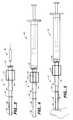
- FIG. 3is a side view of an introducer and pledget prior to placement within the introducer
- FIG. 4is a side view of an introducer having a pledget positioned within the introducer staging chamber and a syringe attached to the introducer;
- FIG. 5is a side view of the introducer and syringe with the pledget hydrated and advanced to a delivery chamber within the introducer;
- FIG. 6is a side cross sectional view of a punctured blood vessel with the introducer and plunger positioned for delivery of the pledget;
- FIG. 7is a side cross sectional view of a punctured blood vessel with the pledget being deposited at the puncture site;
- FIG. 8is a side cross sectional view of a punctured blood vessel with a hydrated and kneaded pledget deposited at the puncture site, the guidewire removed, and the delivery system being withdrawn;
- FIG. 9is a side cross sectional view of a punctured blood vessel with a hydrated and kneaded pledget facilitating hemostasis of the puncture site;
- FIG. 10is a side cross sectional view of an alternative embodiment of an introducer
- FIG. 11is a cross sectional view of a distal end of an introducer according to another alternative embodiment having a central channel for receiving the guidewire;
- FIG. 12is a cross sectional side view of a distal end of an introducer with a connector for connecting a syringe
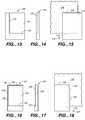
- FIG. 13is a bottom view of a template for use in forming a pledget
- FIG. 14is a side view of the template of FIG. 13;
- FIG. 15is a top view of the template of FIG. 13 as it is placed for cutting a piece of a sponge sheet for formation of the pledget;
- FIG. 16is a bottom view of an alternative embodiment of a template for use in forming a pledget
- FIG. 17is a side view of the template of FIG. 16;
- FIG. 18is a top view of the template of FIG. 16 as it is placed for cutting a piece from a sponge sheet for formation of the pledget;
- FIG. 19is a bottom view of an alternative embodiment of a template having creasing ribs
- FIG. 20is an end view of the template of FIG. 19;
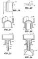
- FIG. 21is a side cross sectional view of a vent cap
- FIG. 22is a side cross sectional view of the vent cap of FIG. 21 positioned on the distal end of a delivery chamber;
- FIG. 23is a side cross sectional view of an alternative embodiment of a vent cap
- FIG. 24is a side cross sectional view of the vent cap of FIG. 23 positioned on a staging chamber;
- FIG. 25is a side view of a pusher for use in the present invention having a proximal stop and a sliding luer;
- FIG. 26is a side cross sectional view of the distal end of a pusher having a funnel shaped distal lumen
- FIG. 27is a side view partially in cross section of an introducer with the pusher of FIG. 25;
- FIG. 28 ais a side cross sectional view of an introducer with a pusher having a rachet system
- FIG. 28 bis an enlarged view of the detail B of FIG. 28 a showing the ratchet teeth and tab;
- FIG. 28 cis a side cross sectional view of an introducer with a detent
- FIGS. 28 d-fare side views of pushers for use with the introducer of FIG. 28 c;
- FIG. 29is a top view of a pledget delivery system including a two piece introducer with separate staging and delivery chambers;
- FIG. 30is a side view of the assembled introducer of FIG. 29 for delivery of the pledget from a staging chamber to the delivery chamber;
- FIG. 31is a side view of the delivery chamber with the pusher connected to the delivery chamber for delivery of the pledget;
- FIG. 32is a side view of the delivery chamber and pusher after delivery of the pledget
- FIG. 33is a side view of a distal end of the dilator having a distal protrusion for strain relief;
- FIG. 34is a side view of a distal end of a dilator having a distal lumen providing a strain relief feature
- FIG. 35is a side cross sectional view of a pledget with a rapidly dissolvable tip
- FIG. 36is a side cross sectional view of a punctured blood vessel with the pledget of FIG. 35 being deposited;
- FIG. 37is a schematic side view of a system for delivering a pledget through a sheath
- FIG. 38is a schematic side view of an alternative system for delivering a pledget through a sheath
- FIG. 39is a flow diagram illustrating a method of hydrating a sponge material for delivery to a body.
- FIG. 40is a flow diagram illustrating another method of hydrating a sponge material for delivery to a body.
- An over the wire delivery systemdelivers an absorbable sponge pledget in a hydrated condition to a blood vessel puncture site to achieve hemostasis.
- One embodiment of the over the wire delivery systemincludes a tract dilator 10 , an introducer 12 , and a pusher 14 , illustrated in kit form in FIG. 1 .
- the systemallows over the wire delivery of the absorbable sponge material directly to the puncture site to achieve hemostasis. Over the wire delivery ensures that the sponge material is properly positioned to fully occlude the puncture.
- the absorbable sponge materialis delivered in a hydrated state which immediately expands to stop blood flow through the puncture.
- the introducerallows the delivery of more absorbable sponge material through a smaller tract by hydrating and compressing the absorbable sponge material.
- “Pledget”means a piece of sponge formed into a generally elongated shape having a size which allows delivery in a hydrated state through a delivery cannula or introducer to a site of a puncture in a blood vessel.
- “Sponge”means a biocompatible material which is capable of being hydrated and is resiliently compressible in a hydrated state.
- the spongeis non-immunogenic and may be absorbable or non-absorbable.
- “Absorbable sponge”means sponge which when implanted within a human or other mammalian body is absorbed by the body.
- “Hydrate”means to partially or fully saturate with a fluid, such as, saline, water, contrast agent, thrombin, therapeutic agents, or the like.
- “Kneading” of the absorbable sponge materialmeans both dry and wet manipulation of sponge material which compresses, enlarges, or changes the shape of the sponge material causing the sponge material to have improved expansion response.
- the tract dilator 10 , the introducer 12 , and the pusher 14may be provided to a medical facility in the form of a kit or individually.
- the tract dilator 10 as illustrated in FIGS. 1 and 2includes a distal tip 20 , a proximal end 22 , and a lumen 24 extending from the distal tip to the proximal end of the tract dilator.
- the lumen 24is provided to allow the tract dilator 10 to be received over a guidewire 26 which extends through the puncture wound 100 into the blood vessel 102 .
- the tract dilator 10may have a constant cross section or may taper slightly to a smaller diameter at the distal tip 20 .
- the tract dilator 10may have a narrow shaft with an enlarged distal tip.
- the distal tip 20has rounded edges to prevent catching on subcutaneous tissue 104 as the tract dilator 10 is inserted through the skin 106 and tissue to the blood vessel puncture site.
- the tract dilator distal tip 20has a diameter such that the tip of the tract dilator will not pass into the blood vessel but will stop and provide tactile feedback when it reaches the external blood vessel wall 102 .
- Other embodiments of tract dilatorswill be discussed below with respect to FIGS. 33 and 34.
- a depth indicator 30is positioned around the tract dilator 10 and is movable in an axial direction. Once the tract dilator 10 has been inserted until the distal tip 20 abuts the external wall of the blood vessel 102 , as shown in FIG. 2, the depth indicator 30 is manually positioned adjacent the patient's skin 106 . Alternatively, the depth indicator 30 can be pushed to a depth indicating position by the skin 106 as the dilator is inserted.
- the depth indicator 30is an elastic ring which is movable axially on the tract dilator 10 and maintains a measured position for comparison with the introducer 12 .
- FIGS. 1 and 3A side view of an introducer 12 is illustrated in FIGS. 1 and 3.
- the introducer 12includes a staging chamber 34 for receiving an absorbable sponge pledget 40 and a delivery chamber 36 for receipt of a hydrated and compressed pledget from the staging chamber.
- a tapered section 38is provided between the staging chamber 34 having a larger diameter lumen and the delivery chamber 36 having a smaller diameter lumen.
- the tapered section 38 of the introducer 12acts as a compression member to compress the hydrated pledget 40 into the delivery chamber.
- the introducer 12also includes a luer fitting 42 at a proximal end for connection to a conventional syringe and wing members 44 for use in grasping the introducer.
- a two part introducer having separate delivery and staging chamberswill be discussed below with respect to FIGS. 29-31.
- the absorbable sponge pledget 40is formed from a sheet of absorbable sponge material which has been cut into a rectangular shape and rolled to form a compact, substantially cylindrical, elongated pledget.
- the pledget 40is sized to be received within the staging chamber 34 of the introducer 12 in a dry rolled state. Templates for use in forming the pledget 40 are shown in FIGS. 13-20.
- a conventional syringe 50 containing a hydrating fluidis connected to the luer fitting 42 , as shown in FIG. 4 .
- the pledget 40is then hydrated within the staging chamber 34 by injecting a fluid into the staging chamber from the syringe 50 causing the pledget to swell, partially or fully blocking the lumen of the introducer.
- the partial hydration or wetting of the exterior surface of the pledget 40creates a lubricous surface on the pledget.
- the hydrated pledget 40is then forced into the delivery chamber 36 by injecting additional fluid with the syringe 50 to force the pledget through the tapered section 38 to the delivery chamber 36 .
- the venturi effectwill help to draw the pledget into the delivery chamber 36 .
- a fingermay be placed over the distal end of the introducer 12 during delivery of the pledget 40 to the delivery chamber 36 to prevent the pledget from being ejected from the introducer by the pressure of the fluid.
- one or more vent holes 46are provided in the side walls of the introducer adjacent the distal tip to allow air and liquid to escape from the introducer while the pledget 40 is positioned for delivery. These vent holes 46 are small enough to prevent the pledget 40 from passing substantially into the vent holes.
- a removable vent capmay be used as described below with respect to FIGS. 21-24. Further, the vent holes 46 may be omitted and a screen or a cap having a screen may be used to allow fluid to pass through the screen while the screen prevents the pledget 40 from being ejected.
- Another alternative method for positioning the pledget adjacent the distal end of the delivery chamberis to provide a proximal vent hole in the side wall of the delivery chamber.
- the proximal vent holeis positioned such that when the pledget has moved to the distal end of the delivery chamber, the pledget is substantially clear of the proximal vent allowing additional injected fluid to pass out of the delivery chamber through the vent.
- the proximal ventacts as a fluid release valve to prevent further advancement of the pledget once the pledget has reached a desired position.
- the introducer 12also includes a depth indicator 52 which is an axially movable member used to indicate the depth to which the introducer should be inserted into the patient to achieve the proper positioning of the pledget 40 at the puncture site.
- the depth indicator 52 of the introducer 12is aligned with the depth indicator 30 on the tract dilator 10 to achieve proper pledget delivery positioning.
- the introducer 12may be formed in any known manner such as by injection molding from a plastic material.
- the introducer 12is transparent so that the pledget 40 can be viewed through the introducer and the user can visually confirm the pledget position.
- the introducer lumenmay be provided with a friction reducing coating for improved pledget delivery. The delivery fluid also reduces friction for improved delivery by wetting the exterior surface of the pledget.
- the pusher 14includes a distal end 56 which is configured to slide within the lumen of the delivery chamber 36 of the introducer 12 .
- a distal end 56which is configured to slide within the lumen of the delivery chamber 36 of the introducer 12 .
- a resilient pusher distal end 56 or a sealing member on the pusher 14may be used to accomplish or approach a resilient fit between the introducer 12 and the pusher.
- the pusher 14also may include a fitting 58 for connecting the proximal end of the pusher to the proximal end of the introducer 12 .
- the fitting 58acts as a stop to limit the motion of the pusher 14 with respect to the introducer 12 .
- a female luer fitting 60may also be included at the proximal end of the pusher 14 for connection of a syringe to the pusher for injection of beneficial agent through the pusher.
- FIGS. 2-9One method of delivering an absorbable sponge pledget 40 to facilitate hemostasis of a blood vessel puncture wound will now be described with respect to the steps illustrated in FIGS. 2-9.
- a guidewire 26is already in place passing through the subcutaneous tissue into the blood vessel.
- the guidewireis inserted through an access sheath used in the intravascular procedure and the access sheath is then removed.
- the guidewire 26is maintained in place with a proximal end extending from the patient's body and a distal end extending through the skin 106 and subcutaneous tissue 104 , through the blood vessel puncture 100 , and into the blood vessel 102 .
- the tract dilator 10is threaded over the guidewire 26 and advanced down through the subcutaneous tissue 104 to an outside surface of the blood vessel 102 . Resistance is felt when the tract dilator distal tip 20 contacts the exterior of the blood vessel and the tract dilator will not easily pass though the vessel puncture 100 and into the vessel.
- the depth indicator 30 on the tract dilator 10is moved to abut the skin surface 106 indicating a distance from the skin surface to the blood vessel puncture site.
- the tract dilator 10is then removed over the guidewire 26 and the introducer depth indicator 52 is aligned with the tract dilator depth indicator 30 .
- a sheet of absorbable sponge materialis cut into a rectangle, is rolled tightly to form a pledget 40 , and is placed into the staging chamber 34 of the introducer 12 .
- the steps of cutting and rolling the pledget 40 and placing the dry pledget in the introducer staging chamber 34may be performed before or after the intervascular procedure.
- the introducer 12may be provided preloaded with a prepared pledget 40 .
- the syringe 50With the pledget 40 placed in the introducer, the syringe 50 is filled with a hydrating fluid such as saline, thrombin, contrast agent, other therapeutic agent, or the like and attached to the introducer 12 as illustrated in FIG. 4 . Fluid is injected slowly into the introducer 12 to hydrate the pledget 40 . The user then pauses to allow hydration and initial swelling of the pledget 40 . Sufficient hydration may occur in about 20 to 30 seconds or less depending on the size of the pledget 40 .
- the userthen places a finger over the distal end of the introducer 12 and injects fluid with the syringe 50 to force the pledget 40 through the tapered section 38 and into the smaller end or delivery chamber 36 of the introducer 12 . Injection of fluid is stopped when the pledget 40 is positioned at the distal end of the delivery chamber 36 . At this point the syringe 50 is removed and the introducer is loaded over the proximal end of the guidewire 26 for the delivery of the pledget 40 to the puncture site.
- a proximal end of the guidewire 26is fed into the distal end of the introducer 12 though the hydrated and compressed pledget 40 and out the proximal end of the introducer.
- the guidewire 26is fed through substantially the center of the pledget 40 to ensure that the implanted pledget is centered over the blood vessel puncture 100 .
- the guidewiremay be inserted along a side of the pledget 40 , through a separate second lumen of the introducer, through an axial lumen in the pledget, or through a low density center of the pledget.
- the guidewire 26After feeding the guidewire 26 through the introducer, the guidewire 26 is fed through the pusher 14 and the pusher is advanced into the introducer until the distal end 56 of the pusher is in contact with the pledget 40 .
- the introducer 12 and pusher 14are then advanced together down though the skin 106 and the subcutaneous tissue 104 until the depth indicator 52 on the exterior of the introducer is at the skin level.
- the pusher 14is held stationary while the introducer 12 is withdrawn proximally preferably to a distance of about 75% of the length of the compressed, hydrated pledget 40 .
- This 75% withdrawal distancemay be indicated with an appropriate marker on the introducer 12 or the plunger 14 or by contact between the fittings 42 , 58 of the introducer and plunger.
- the portion of the pledget 40 ejected into the tissuequickly expands upon delivery to fill the available space and provide localized compression.
- a slight forward pressureis maintained by the operator on the introducer and pusher to increase local compression for a period of time of approximately 1 minute to allow hemostasis to begin.
- the forward pressurecauses the pledget 40 to be compressed around the puncture site, as shown in FIG. 7 .
- the guidewire 26is then completely removed from the introducer 12 and the pusher 14 .
- the introducer 12is withdrawn the remaining approximately 25% by engaging the fitting 58 of the pusher with the female luer fitting 42 of the introducer to completely discharge the pledget 40 into the subcutaneous tissue 104 above the puncture site 100 .
- a slight forward pressurecan then be maintained by the operator on the introducer 12 and pusher 14 for approximately 1 minute before the introducer and pusher are removed from the tissue tract leaving the absorbable sponge pledget 40 positioned against the outer vessel wall, as shown in FIG. 9, providing local compression and facilitating hemostasis.
- the delivered pledget 40maintains hemostasis until healing of the blood vessel 102 occurs.
- the pledget 40is absorbed by the body over time.
- Gelfoamis a porous, pliable, cross-linked gelatin material and is available commercially in sheet form as pre-compressed or non-compressed sponge.
- the materialmay be provided preformed as a pledget 40 or may be cut with a punch, or a stencil or template and knife and rolled to form a pledget as described above. Once hydrated, the pledget 40 can be easily compressed to fit into a lumen having a smaller cross sectional area than the original cross sectional area of the pledget.
- the kneading of the hydrated pledget 40 during deliveryencourages air trapped within the Gelfoam to be expelled and replaced with fluid, allowing rapid expansion upon delivery.
- a pledget 40 of a pre-compressed Gelfoamis hydrated and kneaded (expelling air) during delivery
- the pledgetwill have the absorption capacity to rapidly expand to many times (e.g., 3 or more times) its original dry volume upon delivery.
- a pledget 40 of the non-compressed Gelfoamis hydrated and kneaded (expelling air) during delivery, the pledget will have the absorption capacity to rapidly expand to its original dry volume upon delivery.
- Abrupt lumen diameter changes within the introducer 12will improve “kneading” of the absorbable sponge material passing through the introducer.
- Manipulation of the dry absorbable sponge materialsuch as the rolling of the pledget 40 , also provides kneading. Kneading improves hydration of the sponge material thereby improving the expansion properties of the hydrated delivered absorbable sponge.
- FIG. 10illustrates one such alternative embodiment of the introducer 12 a in which the delivery chamber of the introducer is provided with two enlarged areas 64 .
- the introducermay be provided with a plurality of staggered irregularities for improved kneading of the absorbable sponge pledget 40 .
- the irregularities, enlargements, or recesseswill preferably have a relatively smooth surface to prevent the absorbable sponge material from becoming caught as it passes through the introducer.
- a length “l” between a distal end of the introducer 12 and the distal most of the irregularities, enlargements, or recessesis sufficient to accommodate the entire hydrated, compressed pledget such that the pledget 40 will not become trapped between the plunger and the enlargements.
- Another alternative embodiment for improved kneading of the pledget 40includes features on the guidewire, such as, irregularities, curves, bends, or the like.
- the guidewire kneading featureswill improve kneading of the pledget 40 as the guidewire 26 is inserted through the pledget.
- pledget deliveryis enhanced by super hydration or rapid hydration of the pledget at high pressure.
- Rapid hydrationmay be accomplished by high pressure injection of a fluid into the introducer 12 while placing a finger or vent cap over the distal end of the introducer.
- Super hydrationcan also be achieved by placing the introducer 12 , with the pledget 40 inside, into a pressurized container of fluid.
- fluid pressuresPreferably, fluid pressures of 5 psi or greater are used for super hydration of the sponge material. This super hydration provides rapid and complete hydration of the material in preparation for use.
- the embodiment of FIG. 10also includes a delivery chamber 36 a provided with internal barbs 66 which help to retain the compressed pledget 40 positioned adjacent the distal end of the introducer 12 a while the guidewire 26 is inserted through the pledget material.
- the internal barbs 66are small enough to not cause interference with the passage of the pusher.
- the barbs 66help to hold the pledget 40 in place as the guidewire 26 is inserted through the pledget.
- other featuresmay be used, such as ribs, a textured surface, holes, or the like.
- One example of an alternative structure for retaining the pledget 40 at the distal end of the introducer 12 a during insertion of the guidewireis a distal counterbore (not shown).
- the counterboremay be formed by cutting a bore in from the distal end of the introducer 12 a which is coaxial with the introducer lumen and has a diameter which is slightly larger than the diameter of the introducer lumen.
- the counterboremay have a length which is approximately the length of the pledget 40 or smaller. Preferably, the length of the counterbore is approximately 2 ⁇ 3 to 1 ⁇ 2 the length of the pledget 40 .
- the barbs 66 , counterbore, and other retention featuresare particularly useful when using a conventional coiled guidewire which creates a significant amount of friction when threaded through the absorbable sponge material.
- a smooth, solid shaft guidewire, a plastic sheathed guidewire, or a hydrophilically coated guidewirecan be used. These smooth guidewires are more easily threaded through the absorbable sponge material.
- a guidewire with a reduced diameter proximal portionwill also facilitate threading of the guidewire 26 through the pledget 40 .
- the plunger 14can be used to hold the pledget 40 in place during threading of the guidewire 26 through the pledget.
- a hydraulic back pressurecan also be created to hold the pledget 40 in place by blocking the proximal end of the introducer 12 , such as by the user's finger. Such a hydraulic back pressure will help to hold the pledget in place in the delivery chamber.
- the introducer 12can be used in place of the dilator and the depth determining step can be performed while inserting the introducer, particularly where a plastic sheathed guidewire, other friction reducing guidewire, or other friction reducing feature is used.
- the use of the introducer 12 as the dilatoreliminates errors which may occur in accurately setting the depth indicator 52 on the introducer.
- the pusher 14is inserted within the introducer 12 and the luer fitting 58 at the proximal end of the pusher is attached to the luer fitting 42 on the introducer.
- This introducer/pusher systemis advanced over a guidewire into the tissue tract to establish the location of the exterior wall of the blood vessel.
- the exterior wall of the blood vesselis palpitated with the introducer/pusher system and the depth indicator 52 on the introducer is set at the skin level.
- an introducer/pusher systemmay be used for dilation in which the pusher 14 or obturator used during dilation is different from the pusher which is used for delivery of the pledget.
- the pusher 14 for use during dilationpreferably has a luer lock at a proximal end which locks to the proximal end of the introducer 12 and has a length such that the distal ends of the pusher and introducer are aligned.
- the systemis then removed from the tissue tract and the pusher 14 is removed from the introducer 12 .
- the introducer 12is then prepared for delivery of the pledget 40 by hydrating and staging the pledget within the introducer.
- the introducer 12is then reintroduced over the guidewire and advanced into the tissue tract to the depth indicated by the depth indicator 52 . In this manner, reliable, accurate, and repeatable placement of the pledget 40 is performed without the use of a separate tract dilator.
- the introduceris inserted to the pledget delivery site through a sheath.
- the sheath with a removable dilator positioned inside the sheathis advanced over the guidewire into a tissue tract to establish the location of an arterial puncture site.
- the dilatoris withdrawn leaving the sheath in place.
- the introducer 12 with prepared pledget 40 and pusher 14are then inserted into the sheath over the guidewire.
- the introducer 12may be locked to the sheath, such as by a luer lock. This will position the distal end of the introducer 12 at the distal end of the sheath in preparation for pledget delivery.
- the combined sheath and introducer systemis used to deposit the pledget in the manner described above.
- a sheathsuch as the sheath which was used during the procedure may be used for delivery of the pledget.
- the sheathis first positioned adjacent the exterior of the blood vessel either by palpating with the sheath and an internal dilator or by any of the known visualization methods such as fluoroscopy.
- the sheathmay be preloaded with the pledget or the pledget may be loaded after sheath positioning.
- the pledgetis delivered by inserting a plunger into the sheath and withdrawing the sheath over the plunger to deposit the pledget adjacent the exterior of the blood vessel.
- a staging chamberis attached to the proximal end of the sheath and the pledget is advanced by fluid injection to the distal end of the sheath.
- the pledgetmay be positioned properly by use of a distal vent or vent cap which allows excess fluid to escape as discussed above.
- a proximal ventmay be provided in the sheath at a location which corresponds to a proximal end of the pledget when the pledget is positioned at a distal end of the sheath.
- the sheathWhen the sheath is used for delivery of the pledget without first removing the sheath from the tissue tract, the sheath is withdrawn until a distal tip of the sheath is adjacent the outer vessel wall. This can be determined by known visualization techniques.
- the staging chamberis then attached to the proximal end of the sheath and used to hydrate and advance the pledget to the distal end of the sheath.
- the pledgetmay be advanced through the sheath around or beside the guidewire. Alternatively, the guidewire may be removed before the pledget is conveyed into the sheath.
- a proximal ventas described above, is preferably used to position the pledget at the distal end of the sheath. The pledget is then delivered with the plunger.
- a sheath 208can also be used for delivery of the pledget 40 without first removing the sheath from the vessel, as shown in the embodiments in FIGS. 37 and 38. In this way, the sheath 208 maintains hemostasis at the vessel puncture site 210 while the distal end of the pledget 40 is positioned at a depth corresponding to the outer surface of the vessel wall 212 .
- the pledget 40can be placed directly into the sheath 208 such as by use of an introducer or staging chamber.
- a proximal vent 214is provided in the sheath 208 to position the pledget at a proper position within the sheath.
- the pledget 40is delivered to the sheath and the proximal end of the pledget is positioned at a depth corresponding to the outer wall of the vessel 212 .
- the proper positioning of the sheath and the pledgetis achieved by locating an imaging marker 216 on the sheath at an outer wall of the vessel 212 .
- the pusher 14is then used to hold the pledget 40 stationary with respect to the vessel while the sheath 208 is withdrawn from the puncture site 210 .
- FIG. 38illustrates an alternative embodiment of a sheath delivery system in which an introducer 12 is used to deliver a pledget 40 into the sheath 208 .
- the sheath 208is maintained in the puncture site 210 during delivery of the pledget into the sheath.
- the introducer 12may be inserted into the sheath 208 and secured to the sheath in a known manner such that the distal end of the pledget 40 is positioned at a depth corresponding to the outer surface of the vessel wall 212 .
- the proper positioningmay be determined by imaging a marker on the sheath 208 that corresponds to the distal end of the introducer 12 .
- positioningcan be determined by imaging either the introducer 12 or the pledget 40 if these elements are formed of an imagable material.
- the plunger 14is then used to hold the pledget 40 in position with respect to the vessel wall 212 while the sheath 208 and introducer 12 are withdrawn from the puncture site.
- the sheath 208maintains hemostasis of the puncture site 210 until a distal tip of the sheath has exited the puncture site.
- the pledget 40is exposed and begins to provide hemostasis.
- the pledgetis left within the tissue tract and provides continued hemostasis.
- FIG. 11illustrates a cross section of a distal end of an introducer 12 b according to an alternative embodiment of the invention in which a central lumen 70 is provided within the introducer for receiving the guidewire 26 .
- the central lumen 70allows the guidewire 26 to be inserted easily through the pledget 40 .
- the central lumen 70is formed by a tube 72 which preferably extends at least the length of the hydrated pledget 40 when the pledget is positioned within the delivery chamber 36 b .
- the tube 72is supported by one or more ribs 74 connected to the exterior of the tube and to the interior wall of the introducer 12 b .
- the pledget 40 for use with this embodimentis either formed with a generally U-shaped cross section to be accommodated in the U-shaped cross section of the delivery chamber 36 b or deforms during loading to surround the one or more ribs 74 and tube 72 .
- FIG. 12shows a proximal end of an introducer 12 connected to a specially designed connector 80 for connecting the introducer to the syringe 50 .
- the connector 80is used when the proximal end of the introducer 12 is larger in diameter than the standard syringe fitting.
- the connector 80includes a first end 82 for connection to the syringe 50 and a second end 84 for connection to the introducer 12 .
- the connector 80is removed from the introducer 12 .
- the pledget 40is then inserted into the introducer 12 and the connector 80 is reattached.
- the syringe 50is then connected to the connector 80 for injection of fluid into the introducer 12 to hydrate, advance, and compress the pledget 40 .
- FIGS. 13-20illustrate three different embodiments of templates for use in cutting a piece of a desired size from a sheet of sponge to form the pledget 40 .
- FIG. 13illustrates a template 108 having a rectangular shaped recess 110 with edges of the recess forming edge guides 112 , 114 . As shown in FIG. 15, the edge guides 112 , 114 of the recess 110 are placed against the edges of a sheet 116 of sponge material. The template 108 is pressed downward and the sponge sheet is cut along two edges 118 , 120 of the template 108 .
- FIGS. 16-18An alternative embodiment of a template 124 is illustrated in FIGS. 16-18.
- the template 124includes a recess 126 with a single edge guide 127 and two pressure rails 128 .
- the pressure rails 128help to securely hold the template 124 on the sponge sheet 116 during cutting along cutting edges 130 , 132 of the template.
- the templates of FIGS. 13 and 16are illustrated with two cutting edges, it should be understood that the templates according to the present invention may include one or more cutting edges depending on the size and shape of the sheet 116 from which the piece of sponge material is to be cut.
- the templatesmay be provided with up to three edge guides 112 , 114 , 127 .
- the templatesare provided with recesses for ease of alignment of the templates with the sheet of sponge material. However, alignment may alternatively be provided by use of transparent templates with edge markings or by alignment with the edges of the template themselves.
- the templatemay be formed of the same size as the sponge piece to be cut without any recess or edge guides.
- FIGS. 19 and 20show an alternative embodiment of a template 136 having a recess 138 and creasing ridges 140 .
- the creasing ridges or ribs 140will create creases in the sponge material to assist in folding or rolling of the pledget 40 .
- Any number of creasing ridges 140may be used depending on the configuration of the pledget to be formed.
- creasing ridges 140may be formed at evenly spaced intervals across the entire template surface.
- the creasing ridges 140are preferably about 0.2 to 1.5 mm wide and about 0.5 to 2 mm high with a spacing of about 0.5 to 5 mm.
- the creasing ridges 140also help to prevent movement between the template 136 and the sponge sheet 116 during cutting.
- the templates 108 , 124 , 136may be separate members included in a puncture closure kit including the introducer and pusher or may be fixed to one of the members of the puncture closure system.
- the templatemay be attached to a staging chamber of the introducer 12 .
- FIGS. 21 through 24illustrate vent caps for assisting in hydrating and staging pledgets within the delivery devices of the present invention.
- the vent capsprovide the ability to more rapidly hydrate the pledget and provide the ability to locate the pledget at a desired axial location within the delivery device.
- vent cap 144for use on the distal end of the introducer 12 is shown in FIG. 21 .
- the vent cap 144is received over the distal end of the introducer 12 , as shown in FIG. 22, with a rim 146 of the cap forming a friction fit with an exterior surface of the introducer.
- the vent cap 144includes an interior dome 148 having a vent hole 150 .
- the vent hole 150has been illustrated in a center of the dome 148 , the vent hole may be located at other positions or may be provided between the vent cap 144 and the distal end of the introducer 12 .
- the vent hole 150allows the operator to apply high pressures with the syringe to the interior of the introducer 12 and allows air and fluid to exit through the vent hole.
- This high pressurecan be used to drive the pledget 40 to the distal end of the introducer and to drive fluid into the pledget causing very rapid hydration of the pledget material.
- High pressureis intended to mean pressures of about 5 psi or greater.
- the interior dome 148allows a distal end of the pledget 40 to be positioned just distal of the distal end of the introducer 12 .
- the vent cap 144can be removed and the introducer 12 is then inserted over the proximal end of the guidewire and advanced to the puncture site.
- the pledget material extending from the distal end of the introducer 12provides a rounded surface for assisting in passing the introducer through the layers of tissue to the blood vessel puncture site.
- the shape of the interior dome 148 of the vent cap 144may be modified to achieve different positions of the distal end of the pledget with respect to the distal end of the introducer 12 .
- an inverted dome, cone, or cylinder shaped vent capmay be used in which the dome, cone, or cylinder extends partially into the distal lumen of the introducer 12 .
- the interior of the vent capmay be flat.
- FIG. 23illustrates an alternative embodiment of a vent cap 156 which is particularly configured for use with the separate staging chamber 170 of the introducer shown in FIG. 29 .
- the vent cap 156preferably includes a luer fitting 158 which is attachable to a distal end of the staging chamber 170 .
- the vent cap 156includes a finger 160 which extends to or into a distal end of the staging chamber 170 .
- the finger 160has a central vent 162 . The use of the vent cap 156 with the finger 160 allows the pledget 40 to be held within the large diameter portion of the staging chamber 170 for quick and easy hydration of the pledget.
- the vent finger 160functions to hold the pledget 40 within the large diameter portion of the staging chamber 170 while injection of fluid by the syringe is utilized to begin to hydrate the pledget and remove air from the staging chamber.
- the partially hydrated pledgetmoves forward to block the vent 162 . If the vent 162 has not been entirely blocked by the pledget, the venturi effect will help draw the pledget toward the vent. Once the vent 162 is blocked, high pressure can be used to drive fluid into the pledget, causing very rapid hydration or super hydration of the pledget material.
- the vent 162has been illustrated in the center of the finger 160 , the vent may be located at other positions or may be provided between the vent cap 156 and the staging chamber 170 .
- a vent cap similar to that illustrated in FIG. 23 with an elongated finger 160may be used.
- the elongated fingerextends all the way to the staging chamber 34 to hold the pledget 40 within the staging chamber during hydration. After hydration of the pledget 40 within the staging chamber 34 , the vent cap with the elongated vent finger is removed and the pledget is advanced into the delivery chamber.
- a cap without a ventcan be used for hydration.
- the ventless capacts as a plug to allow hydration by forcing fluid into the introducer which is oriented in a downward direction. Air displaced from the pledget and introducer escapes upward into the syringe during hydration.
- two of the vent capscan be connected in a single member when used with the same system.
- FIG. 25illustrates an alternative embodiment of a pusher 164 having a proximal stop 166 and a sliding luer 168 or other sliding fitting.
- the proximal stop 166is provided proximal to an enlarged diameter distal portion 172 of the pusher 164 .
- the sliding luer 168is provided with an axial through hole having a diameter which is greater than a diameter of a proximal shaft 174 of the pusher 164 and smaller than the diameter of the proximal stop 166 .
- the sliding luer 168 or other sliding fittingis configured to be attached to a proximal end of the introducer 12 or of a delivery chamber portion of a two part introducer.
- the proximal movement of the pusher shaft 174 relative to the introduceris limited by the proximal stop 166 abutting the distal face of the sliding luer 168 .
- This configuration of the pusher 164is illustrated most clearly in FIG. 27 in which the pusher is illustrated as it is used with the introducer 12 .
- the pusher 164is illustrated in FIG. 27 prior to connection of the sliding luer 168 to the mating luer 42 on the introducer 12 .
- the mating luer 42is locked to the sliding luer 168 , the pledget 40 is confined between the distal end of the pusher 164 and the vent cap 144 which has been used to stage the pledget.
- the systemis ready for delivery of the pledget 40 by advancing the system including the introducer 12 and the pusher 164 over a guidewire to the target site. Because the proximal movement of the pusher 164 is preset by the proximal stop 166 , the pledget 40 cannot be displaced proximally during advancement over the guidewire.
- the pusher 164also includes a proximal luer 176 which can be attached to the sliding luer 168 after delivery of the pledget 40 . The introducer and pusher system can then be used to apply pressure to the pledget for local compression until hemostasis is achieved.
- the proximal stop 166has been described as formed by an enlarged diameter portion of the pusher 164 . However, the proximal stop may also be provided by a disk or other protruding member on the pusher shaft or by a detent and corresponding projection.
- the functions of the sliding luer 168 and proximal stop 166can be achieved with other features.
- one or more detents, reliefs, or ratchet teeth provided on the pusher shaftmay engage corresponding features on the introducer to locate the pusher at a desired position and prevent proximal movement of the pusher.
- FIGS. 28 a-fillustrate examples of these systems.
- FIGS. 28 a and 28 billustrate an alternative embodiment of an adjustable proximal stop employing a ratchet mechanism.
- the introducer 12includes one or more tabs 210 which engage ratchet teeth 212 on the pusher 14 to limit proximal motion of the pusher after insertion.
- This systemimproves deployment control by allowing the pusher position to be maintained at any point during deployment.
- the ratchet teeth 212extend along at least a portion of the shaft of the pusher 14 .
- One or more ratchet tabs 210interact with the teeth 212 of the pusher, as shown most clearly in FIG. 28 b.
- FIG. 28 aillustrates the use of the ratchet system to position the pusher 14 adjacent the proximal end of the pledget 40 and trap the pledget between the pusher and the vent cap 144 in preparation for use.
- the ratchet teeth 212allow the system to accommodate pledgets 40 of varying sizes.
- the ratchet systemcan also provide for partial deployment of the pledget 40 while continuing to provide resistance to proximal motion of the pusher 14 . This can be beneficial for example, for guidewire removal and/or system advancement with the pledget 40 in a partially deployed state.
- ratchet tabs 210have been illustrated on the introducer 12 and the ratchet teeth 212 have been illustrated on the pusher 14 , these elements may also be reversed.
- the ratchet teeth and tabsmay also be provided on other portions of the system that interact, such as handles, luers, locks, or the sliding luer illustrated in FIG. 25 .
- FIGS. 28 c-fillustrate systems having other features for resistance to axial sliding of the pusher 14 .
- the introducer 12is provided with one or more detents 214 .
- the constant diameter pusher 14 d of FIG. 28 dis engaged by the detent 214 and provides a friction fit.
- FIGS. 28 e and 28 fshow alternative embodiments of pushers 14 e , 14 f having features which snap over the detent 214 . These features include the grooves 216 and the proximal stop 218 .
- the detent 214can advantageously provide tactile feedback of pusher location to the user. As with the embodiment of FIG. 28 a employing ratchet teeth and tabs, the detent 214 and corresponding features may be located on different parts of the system.
- FIG. 26illustrates one preferred embodiment of the distal end of the pusher 164 having an interior funnel 178 for ease in loading the pusher over a guidewire.
- the distal funnel 178guides the guidewire smoothly into the lumen of the pusher.
- the distal funnel 178provides a particular advantage for facilitating blind loading of the pusher 164 over a guidewire when the pusher is already positioned within the introducer 12 or another delivery system.
- FIGS. 29-32illustrate one preferred delivery system according the present invention in which the introducer is a two part introducer including a separate staging chamber 170 and a delivery chamber 180 .
- the entire delivery system of FIG. 29preferably includes the staging chamber 170 , the delivery chamber 180 , the pusher 164 , and one or more vent caps for the staging and/or delivery chambers such as those illustrated in FIGS. 21 and 23.
- the staging chamber 170is used with the vent cap 156 of FIG. 23 and a syringe for hydration of the pledget 40 within the staging chamber.
- the vent cap 156is then removed from the staging chamber 170 and the staging chamber is connected to the delivery chamber as illustrated in FIG. 30 .
- the pledget 40is advanced from the staging chamber 170 to the delivery chamber 180 by attaching a syringe to a luer fitting 184 at the proximal end of the staging chamber and providing the vent cap 144 on the distal end of the delivery chamber 180 . With this assembly, the hydrated pledget is advanced to the distal end of the delivery chamber 180 . The staging chamber 170 is then removed from the delivery chamber 180 in preparation for pledget delivery.
- the pusher 164is inserted into the delivery chamber 180 , the sliding luer 168 is fixed to a distal luer 186 of the delivery chamber, and the vent cap 144 is removed.
- This systemis used as previously described to deliver the pledget 40 over a guidewire to a delivery site.
- FIG. 32illustrates the delivery system of FIG. 31 after the pledget 40 has been delivered by relative movement between the pusher 164 and the delivery chamber 180 .
- the proximal luer 176 of the pusher 164is engaged with the sliding luer 168 and the system may be used to apply pressure in the direction of the arrow P to provide local compression and promote hemostasis.
- the delivery system employing separate staging and delivery chambers 170 , 180provides the advantage of a shorter delivery system which can be handled more easily and used with shorter guidewires.
- the two component introducer systemalso allows components to be mixed and matched.
- one staging chamber 170maybe used with multiple delivery chambers 180 of different sizes.
- the staging and delivery chamberscan be formed of different materials for their different material properties. For example, it may be desirable to have a transparent plastic staging chamber 170 so that the user can view the pledget within the staging chamber and determine when the pledget has been completely hydrated. It may also be desirable to have a delivery chamber 180 formed of stainless steel or other opaque material which is strong, relatively thin, and less expensive to manufacture.
- FIGS. 33 and 34illustrate alternative embodiments of dilators having distal ends with dilator strain relief features.
- Conventional dilatorshave distal ends with relatively blunt or spherical shapes and having dilator lumens which extend through the length of the dilator and are sized to accomodate a guidewire.
- the leading blunt or rounded edge of the dilatoroften encounters tissue layers within the subtutaneous tissue that require substantial force to advance the dilator through these layers.
- a difficult tissue layermay yield both axially and laterally under the load applied by the dilator. Lateral movement of the dilator can cause significant deflection of the guidewire and often results in a kinked guidewire. This increases the challenge of properly introducing the dilator into the tissue tract.
- FIG. 33illustrates a dilator 190 having a flexible distal extension 192 with a diameter which is much smaller than an outer diameter of the dilator.
- the dilator 190may have a diameter of about 3 to 5 mm while the extension 192 has a diameter of about 1 to 2 mm.
- the small diameter flexible distal extension 192helps to guide the guidewire into the dilator 190 and reduces the stress concentration on the guidewire when difficult tissue layers are encountered.
- FIG. 34Another alternative embodiment of a dilator 196 is illustrated in FIG. 34 in which a funnel shaped lumen 198 at a distal end of the dilator provides a guidewire strain relief feature.
- the enlarged distal opening 200 of the dilator 196allows some guidewire deflection to occur without kinking the guidewire as the dilator is advanced over the guidewire.
- the funnel shaped lumen 198also allows easier passage of kinked guidewires.
- the absorbable sponge delivery systempermits the delivery of more absorbable sponge material down a smaller tract by hydrating and compressing the absorbable sponge material.
- the over the wire delivery methodensures that the absorbable sponge pledget 40 is delivered directly over the puncture site and remains in the proper position while hemostasis is achieved.
- the vessel depth indicator systemensures that the absorbable sponge material is positioned adjacent the exterior of the blood vessel and does not extend into the blood vessel to possibly induce thrombosis.
- the kneading of the absorbable sponge material during rolling of the dry sponge and while hydrated and passing through the introducerimproves the expansion properties of the sponge material.
- the absorbable sponge materialcan be absorbed by the body in a period of time between several days and several months depending on the absorbable sponge material used.
- a pledget 40 formed of commercially available Gelfoam materialwill be absorbed by the body within 1 to 6 weeks.
- the pledget materialmay be engineered to provide different rates of absorption.
- Gelfoamcan be designed to be absorbed at different rates by varying the degree of cross-linking.
- the pledget 40is designed to be absorbed in less than one month.
- non-absorbable spongemay also be delivered with the devices, systems, and methods of the present invention.
- a non-absorbable spongemay be desirable where it will be necessary to locate the blood vessel puncture after the procedure.
- the pledget 40has been described as formed from a rectangular shaped piece of an absorbable sponge material which is rolled into a cylindrical shape, the pledget may also be formed in different shapes and rolled from different shaped sheets.
- the pledget 40may be preformed in a variety of cross sections including circular, rectangular, star, or other multi-sided shape.
- the pledget 40may have a folded cross section and may have through or blind holes formed in the dry pledget.
- the pledget size and shapecan be matched to the size and shape of a particular delivery site.
- a continuous structure of the delivered absorbable sponge pledget 40provides more secure and reliable placement of a plug of material against the blood vessel puncture than a paste or liquid.
- the continuous sponge structurecan even facilitate partial withdrawal, removal, or movement of the ejected pledget.
- the absorbable sponge materialcan be hydrated with a clotting agent such as thrombin, a contrast agent, another beneficial agent, a combination of agents, or the like.
- a clotting agentsuch as thrombin, a contrast agent, another beneficial agent, a combination of agents, or the like.
- the pledget materialitself may contain an agent such as a clotting agent, a contrast agent, another beneficial agent, a combination of agents, or the like.
- the absorbable sponge pledget 40may be presoaked with a beneficial agent such as thrombin for delivery of the beneficial agent to the punctured blood vessel.
- a beneficial agentsuch as thrombin
- the pledget 40may be hydrated with a beneficial liquid agent used as the hydrating fluid within the syringe 50 .
- the beneficial agentmay be delivered to the pledget 40 after the pledget is ejected at the blood vessel puncture site through the lumen of the pusher 14 or through the introducer 12 .
- the treatment of a blood vessel puncture with a hydrated and injected pledget 40 of absorbable sponge to facilitate hemostasisprovides substantial advantages in comfort over external pressure methods.
- the present inventionalso provides advantages over the insertion of an absorbable sponge material in a dry state or injection of a liquid or paste.
- the hydration and manipulation or “kneading” of the hydrated Gelfoam pledget 40 as it is passed through the introducer 12improves the expansion and absorption characteristics of the Gelfoam.
- the injected Gelfoamconforms in shape quickly to the shape of the puncture site and immediately begins blocking blood flow through the puncture site and providing local compression.
- a dry piece of sponge materialdoes not swell until the blood has sufficiently saturated the sponge material, which can take up to hours.
- the hydrated and kneaded sponge materialwill expand to a larger size much more quickly when wetted than a piece of dry sponge material when wetted.
- the systemmay be provided in different lengths for use in different patients.
- the pledget 40 size and shapemay also be varied for different patients.
- the absorbable sponge materialshould form a complete plug over the puncture site without expanding into the blood vessel or exiting the skin of the patient. In some instances where the amount of subcutaneous tissue is great it may be desirable to deliver multiple pledgets 40 in spaced apart positions along the tract leading to the puncture site.
- a pledget 40is formed from a rectangular piece of pre-compressed Gelfoam approximately 2 by 3 cm with a thickness of 0.15 cm. The Gelfoam is rolled or folded into a pledget having a length of approximately 3 cm.
- An introducer 12 for delivery of this pledget to a patient with an average amount of subcutaneous tissuehas a staging chamber length of about 2.5 to 6 cm, preferably approximately 3 cm, a staging chamber inner diameter of about 0.12 to 1.5 cm, preferably approximately 0.4 cm, and a delivery chamber 36 which is typically longer than the staging chamber and has an inner diameter smaller than that of the staging chamber of about 1 cm or less, preferably approximately 0.33 cm or less.
- the particular length of the delivery chamber 36depends on both the subcutaneous tissue depth of the patient and the linear expansion of the pledget 40 as it moves from the staging chamber 34 to the delivery chamber.
- An angle made by a wall of the tapered section 38 with a longitudinal axis of the adaptor 12may vary from about 5° to 90°, but is preferably between about 30° and 60°, more preferably approximately 45°.
- the tapered section 38is illustrated with a substantially planar interior surface, when shown in cross section. However, the tapered section 38 may also have a convex or concave surface in cross-section. This example of pledget 40 and introducer 12 configurations is merely exemplary of the present invention.
- the pledget 40may be provided with a rapidly dissolvable tip extending from a distal end of the pledget.
- rapidly absorbable or dissolvable tip materialsinclude water-soluble, biocompatible, non-toxic, and preferably non-immunogenic polymers such as poly vinyl alcohol (PVA) and ploy vinyl pyrrolidone (PVP).
- PVApoly vinyl alcohol
- PVPploy vinyl pyrrolidone
- Other examplescould include gelatin derived from porcine or bovine sources.
- tip materialscould include, but are not limited to, poly lactic-glycolic acid, poly(proline), ploy(ethylene oxide) and carbowaxes, methyl cellulose, carboxymethyl cellulose, poly(acrylic acid), poly(hydroxyethyl methacrylate), poly(acrylamide), natural plant gums, and poly(methyl vinyl ether-maleic anhydride).
- FIGS. 35 and 36illustrate a pledget 40 a with a rapidly dissolvable tip 200 .
- the rapidly dissolvable tip 200is arranged to extend slightly into the blood vessel 102 and will provide an additional locating mechanism which will hold the pledget at the proper position over the puncture after the guidewire is removed as shown in FIG. 36 .
- the tip 200extends from the end of the pledget a length not shorter than one wall thickness of the target vessel and not exceeding one wall thickness plus the lumen diameter of the target vessel.
- Dissolution ratesare preferably sufficient to facilitate complete absorption of the rapidly dissolvable tip in the lumen within time periods as short as one minute and not exceeding 72 hours.
- the pledget with the dissolvable tipcan also be inserted without the use of the guidewire 26 and the dissolvable tip can serve the locating function of the guidewire for accurately positioning the pledget over the blood vessel puncture.
- the rapidly dissolvable tip 200may be formed from a thin walled tube which extends from an end of the pledget.
- the thin walled tubemay be rolled within the pledget.
- the guidewiremay be threaded through the thin walled tube of the dissolvable locating tip or along one side the locating tip.
- the locating tipmay be formed of a non-dissolvable material and may be removable.
- the removable tip materialmay extend through the pledget and all the way to the skin surface. The tip may be withdrawn after a predetermined time when the locating function of the tip is no longer needed.
- FIG. 39illustrates one embodiment of the present invention for a method of hydrating a sponge material for delivery to a body.
- the methodincludes the steps of placing a dry piece of sponge in a container at a first pressure.
- a hydrating fluidis then introduced into the container to hydrate the sponge.
- the pressure within the containeris changed between the first pressure and a second pressure. At least a portion of the hydrating fluid is removed from the sponge, and the sponge is delivered to a bodily site.
- the dry piece of spongeis cut from a sheet of sponge material into a rectangle, or other shape and is rolled tightly to form a pledget.
- the spongeis placed into the container, such as shown in FIGS. 1-8.
- the steps of cutting and rolling the pledget and placing the dry pledget in the containermay be performed before or after the intervascular procedure.
- the containermay be provided preloaded with a prepared pledget.
- a hydrating fluidsuch as saline, thrombin, contrast agent, other therapeutic agent, or the like is injected into the container at a first pressure.
- the pressure within the containeris changed between the first pressure to a second pressure. This change in pressure results in rapid pre-hydration of the sponge or wetting of a substantial portion of the cells of the sponge.
- the spongehas the ability to rapidly saturate with blood and correspondingly rapidly expand upon delivery to a target site.
- the spongeis then delivered to a bodily site.
- the spongemay be delivered using an over the wire delivery device including an introducer and a pusher. It can be appreciated, however, that any type of delivery device can be used to deliver the pre-hydrated sponge to the bodily site.
- the pledgetAfter the pledget is delivered to the bodily site, it will maintain hemostasis until healing of the blood vessel occurs as the pledget is absorbed by the body over time.
- the first pressure within the containeris an ambient pressure.
- the pressure within the container once the sponge is insertedprovides an ambient pressure to begin the rapid pre-hydration of the sponge.
- the methodfurther comprises the step of changing the pressure within the container between the second pressure and a third pressure. Additionally, the pressure within the container can be changed from the third pressure to a fourth pressure or multiple times within the container.
- the spongeis placed in a container, and hydrating fluid is introduced into the container to submerge the sponge.
- the first pressureis then raised to a second pressure which is greater than the first pressure.
- the second pressureis then reduced to a third pressure wherein the third pressure is between the first pressure and the second pressure.
- the first pressure and the third pressureare the same, or the third pressure is less than the first pressure.
- any combination or number of cycles of the changeis pressure can be utilized before excess hydrating fluid is removed from the sponge.
- the spongeis then delivered to the bodily site. The sponge will most often be delivered between ambient and blood pressure.
- the spongeis placed in a container, and hydrating fluid is introduced into the container to submerge the sponge at a first pressure.
- the first pressureis reduced to a second pressure which is less than the first pressure.
- the second pressureis then increased to a third pressure wherein the third pressure is greater than the first pressure.
- the third pressureis the same as the first pressure, or the third pressure is less than the first pressure.
- the change in pressure within the container between the first pressure and the second pressureis about 5 psi to about 100 psi.
- the greater the change in pressurethe more complete the hydration of the interstices of the sponge, and hydration will occur at a faster rate.
- fluid pressures of 5 psi or greaterare used for super hydration of the sponge material.
- This super hydrationprovides rapid and complete hydration of the material before delivery.
- the change in pressure between the first pressure and the second pressureis at least 5 psi.
- the hydrating fluidcan be removed by compressing the sponge. This can occur by compressing the sponge to fit into one end of the container having a smaller cross sectional area than the original cross sectional area of the sponge or by squeezing or compressing the sponge, by centrifuge, or by any other means known to one skilled in the art. This can be performed with the introducer illustrated in FIGS. 1 and 3.
- the spongeis an absorbable sponge.
- absorbable sponge materialwhich is acceptable for use in the present invention is Gelfoam, manufactured by the Upjohn Company. Gelfoam is a porous, pliable, cross-linked gelatin material and is available commercially in sheet form as pre-compressed or non-compressed sponge.
- the hydrating and delivery of the sponge materialmay be used for facilitating hemostasis at a bodily site.
- the hydrating and delivery of the spongemay also be used for providing an imageable marker.
- the hydrating fluidmay include a therapeutic agent or an imageable marker.
- the change in pressure of the containermay be performed by blocking a first end of the container and injecting the hydrating fluid into a second end of the container.
- the usercan block the first end by placing a finger over a first end of the container as shown in FIG. 5, and the hydrating fluid can be injected into the container with a syringe type device to change the pressure within the container from the first pressure to a second pressure.
- FIGS. 21-24illustrate another embodiment in which vent caps are used to block the first end of the container and assist in hydrating the pledget.
- the vent capsprovide the ability to rapidly hydrate the pledget by changing the pressure within the container with the syringe.
- the vent holes in the vent capsallow the operator to apply high pressures with the syringe to the container and allow air and fluid to exit through the vent holes without allowing the pledget to exit the container. It can be appreciated, however, that any method of changing the pressure within the container can be used.
- FIG. 40another method of hydrating a sponge material for delivery to a body is shown.
- the methodincludes the steps of placing a sponge in a container, and repeatedly changing a pressure of a hydrating fluid within the container to hydrate the sponge.
- the spongeis then delivered to a bodily site.
- the methodincludes the step of removing a portion of the hydrating fluid.
- a hydrated sponge with a delivery volume of 0.012 cubic inchhas the ability/capacity to expand 500% to 2500% of its delivery volume in 1 ⁇ 2 to 30 seconds and more preferably 1 ⁇ 2 to 5 seconds when allowed to freely expand in fluids such as water, saline solutions or blood. With this rapid expansion characteristic, the sponge quickly fills the available space to seal the arterial access site.
- Other embodimentsmay include a hydrated sponge with a delivery volume of 0.0003 cubic inches and the ability/capacity to expand 500% to 2500% of its delivery volume in 1 ⁇ 2 to 30 seconds and more preferably 1 ⁇ 2 to 5 seconds when allowed to freely expand in fluids such as water, saline solutions or blood.
- Still other embodimentsmay include a hydrated sponge with a delivery volume of 0.5 cubic inch and the ability/capacity to expand 500% to 2500% of its delivery volume in 2 to 60 seconds and more preferable 2 to 15 seconds when allowed to freely expand in fluids such as water, saline solution or blood.
- Other clinical applicationsmay include, but are not limited to, biopsy site hemostasis and/or site markers, and embolization.
Landscapes
- Health & Medical Sciences (AREA)
- Engineering & Computer Science (AREA)
- Life Sciences & Earth Sciences (AREA)
- Veterinary Medicine (AREA)
- Animal Behavior & Ethology (AREA)
- Biomedical Technology (AREA)
- Heart & Thoracic Surgery (AREA)
- Public Health (AREA)
- General Health & Medical Sciences (AREA)
- Hematology (AREA)
- Medical Informatics (AREA)
- Anesthesiology (AREA)
- Dermatology (AREA)
- Surgery (AREA)
- Cardiology (AREA)
- Nuclear Medicine, Radiotherapy & Molecular Imaging (AREA)
- Molecular Biology (AREA)
- Surgical Instruments (AREA)
Abstract
Description
Claims (34)
Priority Applications (3)
| Application Number | Priority Date | Filing Date | Title |
|---|---|---|---|
| US09/810,931US6610026B2 (en) | 1998-05-01 | 2001-03-16 | Method of hydrating a sponge material for delivery to a body |
| PCT/US2002/005107WO2002074214A1 (en) | 2001-03-16 | 2002-03-13 | Method of hydrating a sponge material for delivery to a body |
| EP02709620AEP1383452A4 (en) | 2001-03-16 | 2002-03-13 | Method of hydrating a sponge material for delivery to a body |
Applications Claiming Priority (3)
| Application Number | Priority Date | Filing Date | Title |
|---|---|---|---|
| US09/071,284US6162192A (en) | 1998-05-01 | 1998-05-01 | System and method for facilitating hemostasis of blood vessel punctures with absorbable sponge |
| US09/263,603US6315753B1 (en) | 1998-05-01 | 1999-03-05 | System and method for facilitating hemostasis of blood vessel punctures with absorbable sponge |
| US09/810,931US6610026B2 (en) | 1998-05-01 | 2001-03-16 | Method of hydrating a sponge material for delivery to a body |
Related Parent Applications (2)
| Application Number | Title | Priority Date | Filing Date |
|---|---|---|---|
| US09/071,284Continuation-In-PartUS6162192A (en) | 1995-09-15 | 1998-05-01 | System and method for facilitating hemostasis of blood vessel punctures with absorbable sponge |
| US09/263,603Continuation-In-PartUS6315753B1 (en) | 1998-05-01 | 1999-03-05 | System and method for facilitating hemostasis of blood vessel punctures with absorbable sponge |
Publications (2)
| Publication Number | Publication Date |
|---|---|
| US20010034509A1 US20010034509A1 (en) | 2001-10-25 |
| US6610026B2true US6610026B2 (en) | 2003-08-26 |
Family
ID=25205067
Family Applications (1)
| Application Number | Title | Priority Date | Filing Date |
|---|---|---|---|
| US09/810,931Expired - Fee RelatedUS6610026B2 (en) | 1998-05-01 | 2001-03-16 | Method of hydrating a sponge material for delivery to a body |
Country Status (3)
| Country | Link |
|---|---|
| US (1) | US6610026B2 (en) |
| EP (1) | EP1383452A4 (en) |
| WO (1) | WO2002074214A1 (en) |
Cited By (111)
| Publication number | Priority date | Publication date | Assignee | Title |
|---|---|---|---|---|
| US20020016612A1 (en)* | 1998-05-01 | 2002-02-07 | Mark Ashby | Device and method for facilitating hemostasis of a biopsy tract |
| US20020188196A1 (en)* | 1999-02-02 | 2002-12-12 | Burbank Fred H. | Cavity-filling biopsy site markers |
| US20030088269A1 (en)* | 2001-11-08 | 2003-05-08 | Sub-Q, Inc. | System and method for delivering hemostasis promoting material to a blood vessel puncture site by fluid pressure |
| US20040019328A1 (en)* | 2001-11-08 | 2004-01-29 | Sing Eduardo Chi | System and method for delivering hemostasis promoting material to a blood vessel puncture site by fluid pressure |
| US20040102730A1 (en)* | 2002-10-22 | 2004-05-27 | Davis Thomas P. | System and method for facilitating hemostasis of blood vessel punctures with absorbable sponge |
| US6849232B2 (en) | 2001-03-12 | 2005-02-01 | Sub-Q, Inc. | Methods for sterilizing cross-linked gelatin compositions |
| US6964658B2 (en) | 2000-05-12 | 2005-11-15 | Sub-Q, Inc. | System and method for facilitating hemostasis of blood vessel punctures with absorbable sponge |
| US6984219B2 (en) | 1999-09-23 | 2006-01-10 | Mark Ashby | Depth and puncture control for blood vessel hemostasis system |
| US7025748B2 (en) | 2001-11-08 | 2006-04-11 | Boston Scientific Scimed, Inc. | Sheath based blood vessel puncture locator and depth indicator |
| US7037323B2 (en) | 2001-11-08 | 2006-05-02 | Sub-Q, Inc. | Pledget-handling system and method for delivering hemostasis promoting material to a blood vessel puncture site by fluid pressure |
| US20060099238A1 (en)* | 2004-11-05 | 2006-05-11 | Accessclosure, Inc. | Apparatus and methods for sealing a vascular puncture |
| US7048710B1 (en) | 1998-05-01 | 2006-05-23 | Sub-Q, Inc. | System and method for facilitating hemostasis of blood vessel punctures with absorbable sponge |
| US7175646B2 (en) | 1995-09-15 | 2007-02-13 | Boston Scientific Scimed, Inc. | Apparatus and method for percutaneous sealing of blood vessel punctures |
| US7192436B2 (en) | 2001-11-08 | 2007-03-20 | Sub-Q, Inc. | Pledget-handling system and method for delivering hemostasis promoting material to a blood vessel puncture site by fluid pressure |
| US7229579B1 (en)* | 2001-11-09 | 2007-06-12 | Medsorb Dominicana, S.A. | Method of manufacturing a sponge device |
| US20070135837A1 (en)* | 2005-12-13 | 2007-06-14 | Cardiva Medical, Inc. | Drug eluting vascular closure devices and methods |
| US20070276435A1 (en)* | 2005-12-13 | 2007-11-29 | Cardiva Medical, Inc. | Vascular closure devices and methods providing hemostatic enhancement |
| US20080082122A1 (en)* | 2006-09-13 | 2008-04-03 | Farhad Khosravi | Apparatus and methods for sealing a vascular puncture |
| US20080260598A1 (en)* | 2007-04-17 | 2008-10-23 | Gross Jeffrey M | Devices, methods and systems for hydrating a medical implant material |
| US7455680B1 (en) | 2002-11-04 | 2008-11-25 | Boston Scientific Scimed, Inc. | Apparatus and method for inhibiting blood loss |
| US20080307668A1 (en)* | 2007-06-15 | 2008-12-18 | Sidney Watterodt | Methods and devices for drying coated stents |
| US20090043277A1 (en)* | 2007-08-10 | 2009-02-12 | Donald Lee Sturtevant | Treatment for patients after removal of saphenous vascular material |
| US20090099666A1 (en)* | 2005-08-13 | 2009-04-16 | Amedo Gmbh | Spongy implant |
| US7611479B2 (en) | 1998-05-01 | 2009-11-03 | Sub-Q, Inc. | System and method for facilitating hemostasis of blood vessel punctures with absorbable sponge |
| US7618567B2 (en) | 1998-05-01 | 2009-11-17 | Boston Scientific Scimed, Inc. | Absorbable sponge with contrasting agent |
| US7625352B1 (en) | 1998-05-01 | 2009-12-01 | Sub-Q, Inc. | Depth and puncture control for system for hemostasis of blood vessel |
| US20100106068A1 (en)* | 2008-10-29 | 2010-04-29 | Wilson-Cook Medical Inc. | Endoscopic sheet delivery |
| US20100168767A1 (en)* | 2008-06-30 | 2010-07-01 | Cardiva Medical, Inc. | Apparatus and methods for delivering hemostatic materials for blood vessel closure |
| US7806856B2 (en) | 2005-04-22 | 2010-10-05 | Accessclosure, Inc. | Apparatus and method for temporary hemostasis |
| US20100305505A1 (en)* | 2009-05-29 | 2010-12-02 | Ducharme Richard W | Systems and methods for delivering therapeutic agents |
| US20100312259A1 (en)* | 2001-04-24 | 2010-12-09 | Houser Russell A | Tissue closure devices, device and systems for delivery, kits and methods therefor |
| US20110004170A1 (en)* | 2006-07-12 | 2011-01-06 | Mobius Therapeutics, Llc | Apparatus and Method for Reconstituting a Pharmaceutical and Preparing the Reconstituted Pharmaceutical for Transient Application |
| US7875043B1 (en) | 2003-12-09 | 2011-01-25 | Sub-Q, Inc. | Cinching loop |
| US20110040279A1 (en)* | 2009-08-12 | 2011-02-17 | Medtronic, Inc. | Particle Delivery |
| US20110046665A1 (en)* | 2007-09-12 | 2011-02-24 | Transluminal Technologies, Llc | Closure Device, Deployment Apparatus, and Method of Deploying a Closure Device |
| US7909873B2 (en) | 2006-12-15 | 2011-03-22 | Soteira, Inc. | Delivery apparatus and methods for vertebrostenting |
| US20110137338A1 (en)* | 2009-12-08 | 2011-06-09 | Victor Matthew Phillips | Hemostatic Device and Its Methods of Use |
| US7959634B2 (en) | 2004-03-29 | 2011-06-14 | Soteira Inc. | Orthopedic surgery access devices |
| US20110144661A1 (en)* | 2001-04-24 | 2011-06-16 | Houser Russell A | Tissue closure devices, device and systems for delivery, kits and methods therefor |
| US7985240B2 (en) | 2003-06-04 | 2011-07-26 | Accessclosure, Inc. | Occlusion member and tensioner apparatus and methods of their use for sealing a vascular puncture |
| US7993367B2 (en) | 2007-09-28 | 2011-08-09 | Accessclosure, Inc. | Apparatus and methods for sealing a vascular puncture |
| US8003157B2 (en) | 2007-06-15 | 2011-08-23 | Abbott Cardiovascular Systems Inc. | System and method for coating a stent |
| US8029533B2 (en) | 2008-04-04 | 2011-10-04 | Accessclosure, Inc. | Apparatus and methods for sealing a vascular puncture |
| US8137380B2 (en) | 2007-09-12 | 2012-03-20 | Transluminal Technologies, Llc | Closure device, deployment apparatus, and method of deploying a closure device |
| US8157862B2 (en) | 1997-10-10 | 2012-04-17 | Senorx, Inc. | Tissue marking implant |
| US8167230B2 (en) | 2008-12-11 | 2012-05-01 | Cook Medical Technologies Llc | Endoscopic sheet rolling system |
| US8177792B2 (en) | 2002-06-17 | 2012-05-15 | Senorx, Inc. | Plugged tip delivery tube for marker placement |
| US8187625B2 (en) | 2001-03-12 | 2012-05-29 | Boston Scientific Scimed, Inc. | Cross-linked gelatin composition comprising a wetting agent |
| US8224424B2 (en) | 1999-02-02 | 2012-07-17 | Senorx, Inc. | Tissue site markers for in vivo imaging |
| US8311610B2 (en) | 2008-01-31 | 2012-11-13 | C. R. Bard, Inc. | Biopsy tissue marker |
| US8361054B2 (en) | 2008-12-23 | 2013-01-29 | Cook Medical Technologies Llc | Apparatus and methods for containing and delivering therapeutic agents |
| US8361082B2 (en) | 1999-02-02 | 2013-01-29 | Senorx, Inc. | Marker delivery device with releasable plug |
| US20130060279A1 (en)* | 2011-09-02 | 2013-03-07 | Cardiva Medical, Inc. | Catheter with sealed hydratable hemostatic occlusion element |
| US8394122B2 (en) | 2008-11-12 | 2013-03-12 | Accessclosure, Inc. | Apparatus and methods for sealing a vascular puncture |
| US8401622B2 (en) | 2006-12-18 | 2013-03-19 | C. R. Bard, Inc. | Biopsy marker with in situ-generated imaging properties |
| US8437834B2 (en) | 2006-10-23 | 2013-05-07 | C. R. Bard, Inc. | Breast marker |
| US8447386B2 (en) | 2003-05-23 | 2013-05-21 | Senorx, Inc. | Marker or filler forming fluid |
| US8486028B2 (en) | 2005-10-07 | 2013-07-16 | Bard Peripheral Vascular, Inc. | Tissue marking apparatus having drug-eluting tissue marker |
| US8498693B2 (en) | 1999-02-02 | 2013-07-30 | Senorx, Inc. | Intracorporeal marker and marker delivery device |
| US8506592B2 (en) | 2008-08-26 | 2013-08-13 | St. Jude Medical, Inc. | Method and system for sealing percutaneous punctures |
| US8518063B2 (en) | 2001-04-24 | 2013-08-27 | Russell A. Houser | Arteriotomy closure devices and techniques |
| US8551139B2 (en) | 2006-11-30 | 2013-10-08 | Cook Medical Technologies Llc | Visceral anchors for purse-string closure of perforations |
| US8579931B2 (en) | 1999-06-17 | 2013-11-12 | Bard Peripheral Vascular, Inc. | Apparatus for the percutaneous marking of a lesion |
| US8626269B2 (en) | 2003-05-23 | 2014-01-07 | Senorx, Inc. | Fibrous marker and intracorporeal delivery thereof |
| US8634899B2 (en) | 2003-11-17 | 2014-01-21 | Bard Peripheral Vascular, Inc. | Multi mode imaging marker |
| US8647368B2 (en) | 2009-04-03 | 2014-02-11 | Cook Medical Technologies Llc | Tissue anchors and medical devices for rapid deployment of tissue anchors |
| US8670818B2 (en) | 2008-12-30 | 2014-03-11 | C. R. Bard, Inc. | Marker delivery device for tissue marker placement |
| US8668737B2 (en) | 1997-10-10 | 2014-03-11 | Senorx, Inc. | Tissue marking implant |
| US8718745B2 (en) | 2000-11-20 | 2014-05-06 | Senorx, Inc. | Tissue site markers for in vivo imaging |
| US8721680B2 (en) | 2012-03-23 | 2014-05-13 | Accessclosure, Inc. | Apparatus and methods for sealing a vascular puncture |
| US8740937B2 (en) | 2007-05-31 | 2014-06-03 | Cook Medical Technologies Llc | Suture lock |
| USD715442S1 (en) | 2013-09-24 | 2014-10-14 | C. R. Bard, Inc. | Tissue marker for intracorporeal site identification |
| USD715942S1 (en) | 2013-09-24 | 2014-10-21 | C. R. Bard, Inc. | Tissue marker for intracorporeal site identification |
| USD716451S1 (en) | 2013-09-24 | 2014-10-28 | C. R. Bard, Inc. | Tissue marker for intracorporeal site identification |
| USD716450S1 (en) | 2013-09-24 | 2014-10-28 | C. R. Bard, Inc. | Tissue marker for intracorporeal site identification |
| US8876862B2 (en) | 2011-04-14 | 2014-11-04 | Phillips Medical Llc | Hemostatic device and its methods of use |
| US8911472B2 (en) | 2005-12-13 | 2014-12-16 | Cardiva Medical, Inc. | Apparatus and methods for delivering hemostatic materials for blood vessel closure |
| US8961541B2 (en) | 2007-12-03 | 2015-02-24 | Cardio Vascular Technologies Inc. | Vascular closure devices, systems, and methods of use |
| US8992567B1 (en) | 2001-04-24 | 2015-03-31 | Cardiovascular Technologies Inc. | Compressible, deformable, or deflectable tissue closure devices and method of manufacture |
| US9101744B2 (en) | 2009-05-29 | 2015-08-11 | Cook Medical Technologies Llc | Systems and methods for delivering therapeutic agents |
| US9149341B2 (en) | 1999-02-02 | 2015-10-06 | Senorx, Inc | Deployment of polysaccharide markers for treating a site within a patient |
| US9155530B2 (en) | 2010-11-09 | 2015-10-13 | Transluminal Technologies, Llc | Specially designed magnesium-aluminum alloys and medical uses thereof in a hemodynamic environment |
| US9192397B2 (en) | 2006-12-15 | 2015-11-24 | Gmedelaware 2 Llc | Devices and methods for fracture reduction |
| US9205075B2 (en) | 2006-07-12 | 2015-12-08 | Mobius Therapeutics, Llc | Apparatus and method for reconstituting a pharmaceutical and preparing the reconstituted pharmaceutical for transient application |
| US9289195B2 (en) | 2003-06-04 | 2016-03-22 | Access Closure, Inc. | Auto-retraction apparatus and methods for sealing a vascular puncture |
| US9327061B2 (en) | 2008-09-23 | 2016-05-03 | Senorx, Inc. | Porous bioabsorbable implant |
| US9364206B2 (en) | 2008-04-04 | 2016-06-14 | Access Closure, Inc. | Apparatus and methods for sealing a vascular puncture |
| US9386968B2 (en) | 2011-05-11 | 2016-07-12 | Access Closure, Inc. | Apparatus and methods for sealing a vascular puncture |
| US9456816B2 (en) | 2007-09-12 | 2016-10-04 | Transluminal Technologies, Llc | Closure device, deployment apparatus, and method of deploying a closure device |
| US9468428B2 (en) | 2012-06-13 | 2016-10-18 | Phillips Medical Llc | Hemostatic device and its methods of use |
| US9480485B2 (en) | 2006-12-15 | 2016-11-01 | Globus Medical, Inc. | Devices and methods for vertebrostenting |
| US9539241B2 (en) | 2006-07-12 | 2017-01-10 | Mobius Therapeutics, Llc | Apparatus and method for reconstituting a pharmaceutical and preparing the reconstituted pharmaceutical for transient application |
| US20170027557A1 (en)* | 2005-02-07 | 2017-02-02 | Ivy Sports Medicine, Llc | System and method for all-inside suture fixation for implant attachment and soft tissue repair |
| US9579077B2 (en) | 2006-12-12 | 2017-02-28 | C.R. Bard, Inc. | Multiple imaging mode tissue marker |
| US9642604B2 (en) | 2012-04-12 | 2017-05-09 | Phillips Medical Llc | Hemostatic system and its methods of use |
| US9724081B2 (en) | 2013-06-04 | 2017-08-08 | Phillips Medical Llc | Hemostatic system and its methods of use |
| US9757105B2 (en) | 2012-03-23 | 2017-09-12 | Accessclosure, Inc. | Apparatus and methods for sealing a vascular puncture |
| US9820824B2 (en) | 1999-02-02 | 2017-11-21 | Senorx, Inc. | Deployment of polysaccharide markers for treating a site within a patent |
| US9839772B2 (en) | 2008-05-06 | 2017-12-12 | Cook Medical Technologies Llc | Apparatus and methods for delivering therapeutic agents |
| US9839416B2 (en)* | 2013-07-12 | 2017-12-12 | Phillips Medical, LLC | Hemostatic device and its methods of use |
| US9848956B2 (en) | 2002-11-18 | 2017-12-26 | Bard Peripheral Vascular, Inc. | Self-contained, self-piercing, side-expelling marking apparatus |
| US9867931B2 (en) | 2013-10-02 | 2018-01-16 | Cook Medical Technologies Llc | Therapeutic agents for delivery using a catheter and pressure source |
| US9993236B2 (en) | 2009-12-08 | 2018-06-12 | Phillips Medical, LLC | Hemostatic device and its methods of use |
| US10085730B2 (en) | 2013-07-12 | 2018-10-02 | Phillips Medical, LLC | Hemostatic device and its methods of use |
| US20190183468A1 (en)* | 2017-12-14 | 2019-06-20 | Merit Medical Systems, Inc. | Medical plugs, devices for delivering the plugs to voids, and related kits and methods |
| US10342635B2 (en) | 2005-04-20 | 2019-07-09 | Bard Peripheral Vascular, Inc. | Marking device with retractable cannula |
| WO2021234574A1 (en)* | 2020-05-19 | 2021-11-25 | Boston Scientific Limited | Medical delivery systems and methods of using the same |
| US11751859B2 (en) | 2016-04-04 | 2023-09-12 | Merit Medical Systems, Inc. | Medical plug delivery devices with a rotatable magazine and related components and methods |
| US11931227B2 (en) | 2013-03-15 | 2024-03-19 | Cook Medical Technologies Llc | Bimodal treatment methods and compositions for gastrointestinal lesions with active bleeding |
| US11964136B2 (en) | 2016-04-01 | 2024-04-23 | Merit Medical Systems, Inc. | Medical devices for delivering plugs to voids |
| US12226568B2 (en) | 2020-06-05 | 2025-02-18 | Cook Medical Technologies Llc | Medical scopes for delivering therapeutic agents |
Families Citing this family (15)
| Publication number | Priority date | Publication date | Assignee | Title |
|---|---|---|---|---|
| US7189206B2 (en) | 2003-02-24 | 2007-03-13 | Senorx, Inc. | Biopsy device with inner cutter |
| US8282573B2 (en) | 2003-02-24 | 2012-10-09 | Senorx, Inc. | Biopsy device with selectable tissue receiving aperture orientation and site illumination |
| US6511457B2 (en)* | 2001-05-04 | 2003-01-28 | Garey Thompson | Airless syringe |
| EP1833549B1 (en)* | 2004-12-23 | 2016-06-15 | Harvest Technologies Corporation | Hydrating anhydrous graft materials |
| EP2497520B1 (en) | 2007-07-18 | 2022-04-13 | Silk Road Medical, Inc. | Systems for establishing retrograde carotid arterial blood flow |
| US8858490B2 (en) | 2007-07-18 | 2014-10-14 | Silk Road Medical, Inc. | Systems and methods for treating a carotid artery |
| EP2323566A2 (en)* | 2008-08-13 | 2011-05-25 | Silk Road Medical, Inc. | Suture delivery device |
| US8574245B2 (en) | 2008-08-13 | 2013-11-05 | Silk Road Medical, Inc. | Suture delivery device |
| GB0922258D0 (en)* | 2009-12-21 | 2010-02-03 | Smith & Nephew | Device for administration to a wound cavity |
| US10159479B2 (en) | 2012-08-09 | 2018-12-25 | Silk Road Medical, Inc. | Suture delivery device |
| EP3007631A4 (en)* | 2013-06-11 | 2016-11-16 | Promed Inc | Improved vessel access closure |
| US20150289861A1 (en)* | 2014-03-12 | 2015-10-15 | Stb, Ltd. | Devices for use with hemostatic materials |
| CN114366212B (en)* | 2022-01-20 | 2024-03-12 | 苏州大学附属第一医院 | Gelatin sponge strip conveying system for temporary arterial embolism |
| WO2024079289A1 (en)* | 2022-10-12 | 2024-04-18 | Innocoll Pharmaceuticals Limited | A kit for implanting a drug-release implant for laparoscopic surgery |
| US12213676B2 (en)* | 2023-02-22 | 2025-02-04 | eLum Technologies, Inc. | Systems and methods for customizable flow diverter implants |
Citations (97)
| Publication number | Priority date | Publication date | Assignee | Title |
|---|---|---|---|---|
| US581235A (en) | 1897-04-20 | Island | ||
| US1578517A (en) | 1924-12-23 | 1926-03-30 | George N Hein | Valve piston and barrel construction for hypodermic syringes |
| US2086580A (en) | 1935-06-24 | 1937-07-13 | Myron C Shirley | Applicator |
| US2465357A (en) | 1944-08-14 | 1949-03-29 | Upjohn Co | Therapeutic sponge and method of making |
| US2492458A (en) | 1944-12-08 | 1949-12-27 | Jr Edgar A Bering | Fibrin foam |
| US2507244A (en) | 1947-04-14 | 1950-05-09 | Upjohn Co | Surgical gelatin dusting powder and process for preparing same |
| US2558395A (en) | 1947-06-03 | 1951-06-26 | Hoffmann La Roche | Undenatured gelatin hemostatic sponge containing thrombin |
| US2597011A (en) | 1950-07-28 | 1952-05-20 | Us Agriculture | Preparation of starch sponge |
| US2680442A (en) | 1952-04-04 | 1954-06-08 | Frank L Linzmayer | Disposable suppository casing |
| US2761446A (en) | 1955-03-30 | 1956-09-04 | Chemical Specialties Co Inc | Implanter and cartridge |
| US2814294A (en) | 1953-04-17 | 1957-11-26 | Becton Dickinson Co | Unit for and method of inhibiting and controlling bleeding tendencies |
| US2824092A (en) | 1955-01-04 | 1958-02-18 | Robert E Thompson | Process of preparation of a gelatincarboxymethyl cellulose complex |
| US2899362A (en) | 1959-08-11 | Hemostatic sponges and method of | ||
| US3157524A (en) | 1960-10-25 | 1964-11-17 | Ethicon Inc | Preparation of collagen sponge |
| US3724465A (en) | 1971-07-22 | 1973-04-03 | Kimberly Clark Co | Tampon coated with insertion aid and method for coating |
| US4000741A (en) | 1975-11-03 | 1977-01-04 | The Kendall Company | Syringe assembly |
| GB1509023A (en) | 1973-02-12 | 1978-04-26 | Ochsner Med Found Alton | Septal defect closure apparatus |
| GB1569660A (en) | 1976-07-30 | 1980-06-18 | Medline Ab | Occlusion of body channels |
| US4211323A (en)* | 1978-12-01 | 1980-07-08 | California Medical Developments, Inc. | Disposable diagnostic swab having a stored culture medium |
| US4218155A (en)* | 1978-02-10 | 1980-08-19 | Etablissements Armor, S.A. | Stick for applying a liquid |
| SU782814A1 (en) | 1977-01-18 | 1980-11-30 | За витель | Prosthesis for closing defect in heart tissues |
| US4323072A (en) | 1980-01-18 | 1982-04-06 | Shiley, Incorporated | Cannula for a vein distention system |
| US4340066A (en) | 1980-02-01 | 1982-07-20 | Sherwood Medical Industries Inc. | Medical device for collecting a body sample |
| US4390018A (en) | 1980-09-15 | 1983-06-28 | Zukowski Henry J | Method for preventing loss of spinal fluid after spinal tap |
| US4515637A (en) | 1983-11-16 | 1985-05-07 | Seton Company | Collagen-thrombin compositions |
| US4587969A (en) | 1985-01-28 | 1986-05-13 | Rolando Gillis | Support assembly for a blood vessel or like organ |
| US4588395A (en) | 1978-03-10 | 1986-05-13 | Lemelson Jerome H | Catheter and method |
| US4619913A (en) | 1984-05-29 | 1986-10-28 | Matrix Pharmaceuticals, Inc. | Treatments employing drug-containing matrices for introduction into cellular lesion areas |
| US4619261A (en) | 1984-08-09 | 1986-10-28 | Frederico Guerriero | Hydrostatic pressure device for bleeding control through an inflatable, stitchable and retrievable balloon-net system |
| US4645488A (en) | 1982-08-12 | 1987-02-24 | Board Of Trustees Of The University Of Alabama | Syringe for extrusion of wetted, particulate material |
| US4708718A (en) | 1985-07-02 | 1987-11-24 | Target Therapeutics | Hyperthermic treatment of tumors |
| US4744364A (en) | 1987-02-17 | 1988-05-17 | Intravascular Surgical Instruments, Inc. | Device for sealing percutaneous puncture in a vessel |
| US4790819A (en) | 1987-08-24 | 1988-12-13 | American Cyanamid Company | Fibrin clot delivery device and method |
| US4829994A (en) | 1987-05-27 | 1989-05-16 | Kurth Paul A | Femoral compression device for post-catheterization hemostasis |
| US4850960A (en) | 1987-07-08 | 1989-07-25 | Joseph Grayzel | Diagonally tapered, bevelled tip introducing catheter and sheath and method for insertion |
| US4852568A (en) | 1987-02-17 | 1989-08-01 | Kensey Nash Corporation | Method and apparatus for sealing an opening in tissue of a living being |
| US4890612A (en) | 1987-02-17 | 1990-01-02 | Kensey Nash Corporation | Device for sealing percutaneous puncture in a vessel |
| US4900303A (en) | 1978-03-10 | 1990-02-13 | Lemelson Jerome H | Dispensing catheter and method |
| US4929246A (en) | 1988-10-27 | 1990-05-29 | C. R. Bard, Inc. | Method for closing and sealing an artery after removing a catheter |
| US4936835A (en) | 1988-05-26 | 1990-06-26 | Haaga John R | Medical needle with bioabsorbable tip |
| US4950234A (en) | 1987-05-26 | 1990-08-21 | Sumitomo Pharmaceuticals Company, Limited | Device for administering solid preparations |
| US5007895A (en) | 1989-04-05 | 1991-04-16 | Burnett George S | Wound packing instrument |
| US5021059A (en) | 1990-05-07 | 1991-06-04 | Kensey Nash Corporation | Plug device with pulley for sealing punctures in tissue and methods of use |
| US5053046A (en) | 1988-08-22 | 1991-10-01 | Woodrow W. Janese | Dural sealing needle and method of use |
| US5061274A (en) | 1989-12-04 | 1991-10-29 | Kensey Nash Corporation | Plug device for sealing openings and method of use |
| US5080655A (en) | 1988-05-26 | 1992-01-14 | Haaga John R | Medical biopsy needle |
| US5108421A (en) | 1990-10-01 | 1992-04-28 | Quinton Instrument Company | Insertion assembly and method of inserting a vessel plug into the body of a patient |
| US5163904A (en) | 1991-11-12 | 1992-11-17 | Merit Medical Systems, Inc. | Syringe apparatus with attached pressure gauge |
| US5167624A (en) | 1990-11-09 | 1992-12-01 | Catheter Research, Inc. | Embolus delivery system and method |
| US5192301A (en) | 1989-01-17 | 1993-03-09 | Nippon Zeon Co., Ltd. | Closing plug of a defect for medical use and a closing plug device utilizing it |
| US5192300A (en) | 1990-10-01 | 1993-03-09 | Quinton Instrument Company | Insertion assembly and method of inserting a vessel plug into the body of a patient |
| US5195988A (en) | 1988-05-26 | 1993-03-23 | Haaga John R | Medical needle with removable sheath |
| US5220926A (en) | 1992-07-13 | 1993-06-22 | Jones George T | Finger mounted core biopsy guide |
| US5221259A (en) | 1990-12-27 | 1993-06-22 | Novoste Corporation | Wound treating device and method of using same |
| EP0557963A1 (en) | 1992-02-24 | 1993-09-01 | United States Surgical Corporation | Resilient arm mesh deployer |
| US5242683A (en) | 1989-07-21 | 1993-09-07 | Nycomed Imaging As | Contrast media comprising a paramagnetic agent and an iodinated agent for x-ray and mri |
| US5310407A (en) | 1991-06-17 | 1994-05-10 | Datascope Investment Corp. | Laparoscopic hemostat delivery system and method for using said system |
| US5322515A (en) | 1993-03-15 | 1994-06-21 | Abbott Laboratories | Luer adapter assembly for emergency syringe |
| US5325857A (en) | 1993-07-09 | 1994-07-05 | Hossein Nabai | Skin biopsy device and method |
| US5334216A (en) | 1992-12-10 | 1994-08-02 | Howmedica Inc. | Hemostatic plug |
| US5366480A (en) | 1990-12-24 | 1994-11-22 | American Cyanamid Company | Synthetic elastomeric buttressing pledget |
| US5370656A (en) | 1993-02-26 | 1994-12-06 | Merocel Corporation | Throat pack |
| US5383899A (en) | 1993-09-28 | 1995-01-24 | Hammerslag; Julius G. | Method of using a surface opening adhesive sealer |
| US5383896A (en) | 1993-05-25 | 1995-01-24 | Gershony; Gary | Vascular sealing device |
| US5385550A (en) | 1994-03-29 | 1995-01-31 | Su; Chan-Ho | Needle protective means for prevention against stab and virus infection |
| US5388588A (en) | 1993-05-04 | 1995-02-14 | Nabai; Hossein | Biopsy wound closure device and method |
| US5391183A (en) | 1990-09-21 | 1995-02-21 | Datascope Investment Corp | Device and method sealing puncture wounds |
| US5419765A (en) | 1990-12-27 | 1995-05-30 | Novoste Corporation | Wound treating device and method for treating wounds |
| US5431639A (en) | 1993-08-12 | 1995-07-11 | Boston Scientific Corporation | Treating wounds caused by medical procedures |
| US5486195A (en) | 1993-07-26 | 1996-01-23 | Myers; Gene | Method and apparatus for arteriotomy closure |
| US5490736A (en)* | 1994-09-08 | 1996-02-13 | Habley Medical Technology Corporation | Stylus applicator for a rehydrated multi-constituent medication |
| US5522850A (en) | 1994-06-23 | 1996-06-04 | Incontrol, Inc. | Defibrillation and method for cardioverting a heart and storing related activity data |
| US5526822A (en) | 1994-03-24 | 1996-06-18 | Biopsys Medical, Inc. | Method and apparatus for automated biopsy and collection of soft tissue |
| US5540715A (en) | 1992-07-16 | 1996-07-30 | Sherwood Medical Company | Device for sealing hemostatic incisions |
| US5542914A (en) | 1993-02-12 | 1996-08-06 | Kimberly-Clark Corporation | Encapsulated tampon with an applicator |
| US5545178A (en) | 1994-04-29 | 1996-08-13 | Kensey Nash Corporation | System for closing a percutaneous puncture formed by a trocar to prevent tissue at the puncture from herniating |
| US5558853A (en) | 1993-01-25 | 1996-09-24 | Sonus Pharmaceuticals | Phase shift colloids as ultrasound contrast agents |
| US5645566A (en) | 1995-09-15 | 1997-07-08 | Sub Q Inc. | Apparatus and method for percutaneous sealing of blood vessel punctures |
| US5649547A (en) | 1994-03-24 | 1997-07-22 | Biopsys Medical, Inc. | Methods and devices for automated biopsy and collection of soft tissue |
| US5653730A (en) | 1993-09-28 | 1997-08-05 | Hemodynamics, Inc. | Surface opening adhesive sealer |
| US5676689A (en) | 1991-11-08 | 1997-10-14 | Kensey Nash Corporation | Hemostatic puncture closure system including vessel location device and method of use |
| US5681279A (en) | 1996-11-04 | 1997-10-28 | Roper; David H. | Pill dispensing syringe |
| US5769086A (en) | 1995-12-06 | 1998-06-23 | Biopsys Medical, Inc. | Control system and method for automated biopsy device |
| US5800389A (en) | 1996-02-09 | 1998-09-01 | Emx, Inc. | Biopsy device |
| US5810806A (en) | 1996-08-29 | 1998-09-22 | Ethicon Endo-Surgery | Methods and devices for collection of soft tissue |
| US5858008A (en) | 1997-04-22 | 1999-01-12 | Becton, Dickinson And Company | Cannula sealing shield assembly |
| US5902310A (en) | 1996-08-12 | 1999-05-11 | Ethicon Endo-Surgery, Inc. | Apparatus and method for marking tissue |
| US5984950A (en) | 1996-12-23 | 1999-11-16 | Sub-Q, Inc. | Percutaneous hemostasis device |
| US6007563A (en) | 1991-11-08 | 1999-12-28 | Kensey Nash Corporation | Method of deploying percutaneous puncture closure |
| US6027471A (en) | 1995-01-18 | 2000-02-22 | Fallon; Timothy J. | Apparatus for applying a hemostatic agent onto a tissue |
| US6027482A (en) | 1994-12-12 | 2000-02-22 | Becton Dickinson And Company | Syringe tip cap |
| US6071301A (en) | 1998-05-01 | 2000-06-06 | Sub Q., Inc. | Device and method for facilitating hemostasis of a biopsy tract |
| US6161034A (en) | 1999-02-02 | 2000-12-12 | Senorx, Inc. | Methods and chemical preparations for time-limited marking of biopsy sites |
| US6162192A (en) | 1998-05-01 | 2000-12-19 | Sub Q, Inc. | System and method for facilitating hemostasis of blood vessel punctures with absorbable sponge |
| US6183497B1 (en) | 1998-05-01 | 2001-02-06 | Sub-Q, Inc. | Absorbable sponge with contrasting agent |
| US6200328B1 (en) | 1998-05-01 | 2001-03-13 | Sub Q, Incorporated | Device and method for facilitating hemostasis of a biopsy tract |
| US6315753B1 (en)* | 1998-05-01 | 2001-11-13 | Sub-Q, Inc. | System and method for facilitating hemostasis of blood vessel punctures with absorbable sponge |
- 2001
- 2001-03-16USUS09/810,931patent/US6610026B2/ennot_activeExpired - Fee Related
- 2002
- 2002-03-13WOPCT/US2002/005107patent/WO2002074214A1/ennot_activeApplication Discontinuation
- 2002-03-13EPEP02709620Apatent/EP1383452A4/ennot_activeWithdrawn
Patent Citations (115)
| Publication number | Priority date | Publication date | Assignee | Title |
|---|---|---|---|---|
| US2899362A (en) | 1959-08-11 | Hemostatic sponges and method of | ||
| US581235A (en) | 1897-04-20 | Island | ||
| US1578517A (en) | 1924-12-23 | 1926-03-30 | George N Hein | Valve piston and barrel construction for hypodermic syringes |
| US2086580A (en) | 1935-06-24 | 1937-07-13 | Myron C Shirley | Applicator |
| US2465357A (en) | 1944-08-14 | 1949-03-29 | Upjohn Co | Therapeutic sponge and method of making |
| US2492458A (en) | 1944-12-08 | 1949-12-27 | Jr Edgar A Bering | Fibrin foam |
| US2507244A (en) | 1947-04-14 | 1950-05-09 | Upjohn Co | Surgical gelatin dusting powder and process for preparing same |
| US2558395A (en) | 1947-06-03 | 1951-06-26 | Hoffmann La Roche | Undenatured gelatin hemostatic sponge containing thrombin |
| US2597011A (en) | 1950-07-28 | 1952-05-20 | Us Agriculture | Preparation of starch sponge |
| US2680442A (en) | 1952-04-04 | 1954-06-08 | Frank L Linzmayer | Disposable suppository casing |
| US2814294A (en) | 1953-04-17 | 1957-11-26 | Becton Dickinson Co | Unit for and method of inhibiting and controlling bleeding tendencies |
| US2824092A (en) | 1955-01-04 | 1958-02-18 | Robert E Thompson | Process of preparation of a gelatincarboxymethyl cellulose complex |
| US2761446A (en) | 1955-03-30 | 1956-09-04 | Chemical Specialties Co Inc | Implanter and cartridge |
| US3157524A (en) | 1960-10-25 | 1964-11-17 | Ethicon Inc | Preparation of collagen sponge |
| US3724465A (en) | 1971-07-22 | 1973-04-03 | Kimberly Clark Co | Tampon coated with insertion aid and method for coating |
| GB1509023A (en) | 1973-02-12 | 1978-04-26 | Ochsner Med Found Alton | Septal defect closure apparatus |
| US4000741A (en) | 1975-11-03 | 1977-01-04 | The Kendall Company | Syringe assembly |
| GB1569660A (en) | 1976-07-30 | 1980-06-18 | Medline Ab | Occlusion of body channels |
| SU782814A1 (en) | 1977-01-18 | 1980-11-30 | За витель | Prosthesis for closing defect in heart tissues |
| US4218155A (en)* | 1978-02-10 | 1980-08-19 | Etablissements Armor, S.A. | Stick for applying a liquid |
| US4900303A (en) | 1978-03-10 | 1990-02-13 | Lemelson Jerome H | Dispensing catheter and method |
| US4588395A (en) | 1978-03-10 | 1986-05-13 | Lemelson Jerome H | Catheter and method |
| US4211323A (en)* | 1978-12-01 | 1980-07-08 | California Medical Developments, Inc. | Disposable diagnostic swab having a stored culture medium |
| US4323072A (en) | 1980-01-18 | 1982-04-06 | Shiley, Incorporated | Cannula for a vein distention system |
| US4340066A (en) | 1980-02-01 | 1982-07-20 | Sherwood Medical Industries Inc. | Medical device for collecting a body sample |
| US4390018A (en) | 1980-09-15 | 1983-06-28 | Zukowski Henry J | Method for preventing loss of spinal fluid after spinal tap |
| US4645488A (en) | 1982-08-12 | 1987-02-24 | Board Of Trustees Of The University Of Alabama | Syringe for extrusion of wetted, particulate material |
| US4515637A (en) | 1983-11-16 | 1985-05-07 | Seton Company | Collagen-thrombin compositions |
| US4619913A (en) | 1984-05-29 | 1986-10-28 | Matrix Pharmaceuticals, Inc. | Treatments employing drug-containing matrices for introduction into cellular lesion areas |
| US4619261A (en) | 1984-08-09 | 1986-10-28 | Frederico Guerriero | Hydrostatic pressure device for bleeding control through an inflatable, stitchable and retrievable balloon-net system |
| US4587969A (en) | 1985-01-28 | 1986-05-13 | Rolando Gillis | Support assembly for a blood vessel or like organ |
| US4708718A (en) | 1985-07-02 | 1987-11-24 | Target Therapeutics | Hyperthermic treatment of tumors |
| US4890612A (en) | 1987-02-17 | 1990-01-02 | Kensey Nash Corporation | Device for sealing percutaneous puncture in a vessel |
| US4852568A (en) | 1987-02-17 | 1989-08-01 | Kensey Nash Corporation | Method and apparatus for sealing an opening in tissue of a living being |
| US4744364A (en) | 1987-02-17 | 1988-05-17 | Intravascular Surgical Instruments, Inc. | Device for sealing percutaneous puncture in a vessel |
| US4950234A (en) | 1987-05-26 | 1990-08-21 | Sumitomo Pharmaceuticals Company, Limited | Device for administering solid preparations |
| US4829994A (en) | 1987-05-27 | 1989-05-16 | Kurth Paul A | Femoral compression device for post-catheterization hemostasis |
| US4850960A (en) | 1987-07-08 | 1989-07-25 | Joseph Grayzel | Diagonally tapered, bevelled tip introducing catheter and sheath and method for insertion |
| US4790819A (en) | 1987-08-24 | 1988-12-13 | American Cyanamid Company | Fibrin clot delivery device and method |
| US4936835A (en) | 1988-05-26 | 1990-06-26 | Haaga John R | Medical needle with bioabsorbable tip |
| US5195988A (en) | 1988-05-26 | 1993-03-23 | Haaga John R | Medical needle with removable sheath |
| US5080655A (en) | 1988-05-26 | 1992-01-14 | Haaga John R | Medical biopsy needle |
| US5053046A (en) | 1988-08-22 | 1991-10-01 | Woodrow W. Janese | Dural sealing needle and method of use |
| US4929246A (en) | 1988-10-27 | 1990-05-29 | C. R. Bard, Inc. | Method for closing and sealing an artery after removing a catheter |
| US5192301A (en) | 1989-01-17 | 1993-03-09 | Nippon Zeon Co., Ltd. | Closing plug of a defect for medical use and a closing plug device utilizing it |
| FR2641692B1 (en) | 1989-01-17 | 1995-05-12 | Nippon Zeon Co | |
| US5007895A (en) | 1989-04-05 | 1991-04-16 | Burnett George S | Wound packing instrument |
| US5242683A (en) | 1989-07-21 | 1993-09-07 | Nycomed Imaging As | Contrast media comprising a paramagnetic agent and an iodinated agent for x-ray and mri |
| US5061274A (en) | 1989-12-04 | 1991-10-29 | Kensey Nash Corporation | Plug device for sealing openings and method of use |
| US5021059A (en) | 1990-05-07 | 1991-06-04 | Kensey Nash Corporation | Plug device with pulley for sealing punctures in tissue and methods of use |
| US5741223A (en) | 1990-09-21 | 1998-04-21 | Datascope Investment Corp. | Device and method for sealing puncture wounds |
| US5725498A (en) | 1990-09-21 | 1998-03-10 | Datascope Investment Corp. | Device and method for sealing puncture wounds |
| US5830130A (en) | 1990-09-21 | 1998-11-03 | Datascope Investment Corp. | Device and method for sealing puncture wounds |
| US5591204A (en) | 1990-09-21 | 1997-01-07 | Datascope Investment Corp. | Device and method for sealing puncture wounds |
| US5437631A (en) | 1990-09-21 | 1995-08-01 | Datascope Investment Corp. | Percutaneous introducer set and method for sealing puncture wounds |
| US5391183A (en) | 1990-09-21 | 1995-02-21 | Datascope Investment Corp | Device and method sealing puncture wounds |
| US5275616A (en) | 1990-10-01 | 1994-01-04 | Quinton Instrument Company | Insertion assembly and method of inserting a vessel plug into the body of a patient |
| US5108421A (en) | 1990-10-01 | 1992-04-28 | Quinton Instrument Company | Insertion assembly and method of inserting a vessel plug into the body of a patient |
| US5192300A (en) | 1990-10-01 | 1993-03-09 | Quinton Instrument Company | Insertion assembly and method of inserting a vessel plug into the body of a patient |
| US5478352A (en) | 1990-10-01 | 1995-12-26 | Quinton Instrument Company | Insertion assembly and method of inserting a vessel plug into the body of a patient |
| US5275616B1 (en) | 1990-10-01 | 1996-01-23 | Quinton Instr | Insertion assembly and method of inserting a vessel plug into the body of a patient |
| US5601602A (en) | 1990-10-01 | 1997-02-11 | Quinton Instrument Company | Insertion assembly and method of inserting a vessel plug into the body of a patient |
| US5591205A (en) | 1990-10-01 | 1997-01-07 | Quinton Instrument Company | Insertion assembly and method of inserting a vessel plug into the body of a patient |
| US5716375A (en) | 1990-10-01 | 1998-02-10 | Quinton Instrument Company | Insertion assembly and method of inserting a vessel plug into the body of a patient |
| US5167624A (en) | 1990-11-09 | 1992-12-01 | Catheter Research, Inc. | Embolus delivery system and method |
| US5366480A (en) | 1990-12-24 | 1994-11-22 | American Cyanamid Company | Synthetic elastomeric buttressing pledget |
| US5221259A (en) | 1990-12-27 | 1993-06-22 | Novoste Corporation | Wound treating device and method of using same |
| US5419765A (en) | 1990-12-27 | 1995-05-30 | Novoste Corporation | Wound treating device and method for treating wounds |
| US5310407A (en) | 1991-06-17 | 1994-05-10 | Datascope Investment Corp. | Laparoscopic hemostat delivery system and method for using said system |
| US5676689A (en) | 1991-11-08 | 1997-10-14 | Kensey Nash Corporation | Hemostatic puncture closure system including vessel location device and method of use |
| US6007563A (en) | 1991-11-08 | 1999-12-28 | Kensey Nash Corporation | Method of deploying percutaneous puncture closure |
| US5163904A (en) | 1991-11-12 | 1992-11-17 | Merit Medical Systems, Inc. | Syringe apparatus with attached pressure gauge |
| EP0557963A1 (en) | 1992-02-24 | 1993-09-01 | United States Surgical Corporation | Resilient arm mesh deployer |
| US5220926A (en) | 1992-07-13 | 1993-06-22 | Jones George T | Finger mounted core biopsy guide |
| US5540715A (en) | 1992-07-16 | 1996-07-30 | Sherwood Medical Company | Device for sealing hemostatic incisions |
| US5334216A (en) | 1992-12-10 | 1994-08-02 | Howmedica Inc. | Hemostatic plug |
| US5558853A (en) | 1993-01-25 | 1996-09-24 | Sonus Pharmaceuticals | Phase shift colloids as ultrasound contrast agents |
| US5542914A (en) | 1993-02-12 | 1996-08-06 | Kimberly-Clark Corporation | Encapsulated tampon with an applicator |
| US5370656A (en) | 1993-02-26 | 1994-12-06 | Merocel Corporation | Throat pack |
| US5322515A (en) | 1993-03-15 | 1994-06-21 | Abbott Laboratories | Luer adapter assembly for emergency syringe |
| US5467780A (en) | 1993-05-04 | 1995-11-21 | Nabai; Hossein | Biopsy wound closure device and method |
| US5388588A (en) | 1993-05-04 | 1995-02-14 | Nabai; Hossein | Biopsy wound closure device and method |
| US5479936A (en) | 1993-05-04 | 1996-01-02 | Nabai; Hossein | Biopsy wound closure device and method |
| US5383896A (en) | 1993-05-25 | 1995-01-24 | Gershony; Gary | Vascular sealing device |
| US5325857A (en) | 1993-07-09 | 1994-07-05 | Hossein Nabai | Skin biopsy device and method |
| US5486195A (en) | 1993-07-26 | 1996-01-23 | Myers; Gene | Method and apparatus for arteriotomy closure |
| US5431639A (en) | 1993-08-12 | 1995-07-11 | Boston Scientific Corporation | Treating wounds caused by medical procedures |
| US5665107A (en) | 1993-09-28 | 1997-09-09 | Hemodynamics, Inc. | Surface opening adhesive sealer |
| US5383899A (en) | 1993-09-28 | 1995-01-24 | Hammerslag; Julius G. | Method of using a surface opening adhesive sealer |
| US5529577A (en) | 1993-09-28 | 1996-06-25 | Hemodynamics, Inc. | Surface opening adhesive sealer |
| US5653730A (en) | 1993-09-28 | 1997-08-05 | Hemodynamics, Inc. | Surface opening adhesive sealer |
| US5649547A (en) | 1994-03-24 | 1997-07-22 | Biopsys Medical, Inc. | Methods and devices for automated biopsy and collection of soft tissue |
| US5775333A (en) | 1994-03-24 | 1998-07-07 | Ethicon Endo-Surgery, Inc. | Apparatus for automated biopsy and collection of soft tissue |
| US5526822A (en) | 1994-03-24 | 1996-06-18 | Biopsys Medical, Inc. | Method and apparatus for automated biopsy and collection of soft tissue |
| US5385550A (en) | 1994-03-29 | 1995-01-31 | Su; Chan-Ho | Needle protective means for prevention against stab and virus infection |
| US5545178A (en) | 1994-04-29 | 1996-08-13 | Kensey Nash Corporation | System for closing a percutaneous puncture formed by a trocar to prevent tissue at the puncture from herniating |
| US5522850A (en) | 1994-06-23 | 1996-06-04 | Incontrol, Inc. | Defibrillation and method for cardioverting a heart and storing related activity data |
| US5490736A (en)* | 1994-09-08 | 1996-02-13 | Habley Medical Technology Corporation | Stylus applicator for a rehydrated multi-constituent medication |
| US6027482A (en) | 1994-12-12 | 2000-02-22 | Becton Dickinson And Company | Syringe tip cap |
| US6027471A (en) | 1995-01-18 | 2000-02-22 | Fallon; Timothy J. | Apparatus for applying a hemostatic agent onto a tissue |
| US5645566A (en) | 1995-09-15 | 1997-07-08 | Sub Q Inc. | Apparatus and method for percutaneous sealing of blood vessel punctures |
| US5769086A (en) | 1995-12-06 | 1998-06-23 | Biopsys Medical, Inc. | Control system and method for automated biopsy device |
| US5800389A (en) | 1996-02-09 | 1998-09-01 | Emx, Inc. | Biopsy device |
| US5902310A (en) | 1996-08-12 | 1999-05-11 | Ethicon Endo-Surgery, Inc. | Apparatus and method for marking tissue |
| US5810806A (en) | 1996-08-29 | 1998-09-22 | Ethicon Endo-Surgery | Methods and devices for collection of soft tissue |
| US5681279A (en) | 1996-11-04 | 1997-10-28 | Roper; David H. | Pill dispensing syringe |
| US5984950A (en) | 1996-12-23 | 1999-11-16 | Sub-Q, Inc. | Percutaneous hemostasis device |
| US5858008A (en) | 1997-04-22 | 1999-01-12 | Becton, Dickinson And Company | Cannula sealing shield assembly |
| US6071301A (en) | 1998-05-01 | 2000-06-06 | Sub Q., Inc. | Device and method for facilitating hemostasis of a biopsy tract |
| US6086607A (en) | 1998-05-01 | 2000-07-11 | Sub-Q, Inc. | Device and method for facilitating hemostasis of a biopsy tract |
| US6162192A (en) | 1998-05-01 | 2000-12-19 | Sub Q, Inc. | System and method for facilitating hemostasis of blood vessel punctures with absorbable sponge |
| US6183497B1 (en) | 1998-05-01 | 2001-02-06 | Sub-Q, Inc. | Absorbable sponge with contrasting agent |
| US6200328B1 (en) | 1998-05-01 | 2001-03-13 | Sub Q, Incorporated | Device and method for facilitating hemostasis of a biopsy tract |
| US6315753B1 (en)* | 1998-05-01 | 2001-11-13 | Sub-Q, Inc. | System and method for facilitating hemostasis of blood vessel punctures with absorbable sponge |
| US6161034A (en) | 1999-02-02 | 2000-12-12 | Senorx, Inc. | Methods and chemical preparations for time-limited marking of biopsy sites |
Non-Patent Citations (21)
| Title |
|---|
| David J. Allison, M.D., et al., "Percutaneous Liver Biopsy and Track Embolization with Steel Coils", Radiology, 169(1):261-263 (1988). |
| Di Segni, Riccardo, et al. "Part 1. Embolotherapy: Agents, Equipment, and Techniques", vol.4. |
| Fandrich, Christian et al., Small Guage Gelfoam Plug Liver Biopsy in High Risk Patients: Safety and Diagnostic Value Australasian Radiology (1996) 40 pgs, 230-234. |
| Ferdinand Kiemeneij, MD, et al., "Improved Anticoagulation Management After Palmaz Schatz Coronary Stent Implantation by Sealing the Arterial Puncture Site With a Vascular Hemostasis Device", Catheterization and Cardiovascular Diagnosis, 30:317-322 (1993). |
| Gelfoam Sterile Powder Absorable Gelatin Powder, Pharmacia & Upjohn, Inc, The Upjohn Company 1996. |
| Gelfoam Sterile Powder, Absorbable Gelatin Powder 02/96. |
| J.P.M. Foran, et al., "Early Mobilisation After Percutaneous Cardiac Catheterisation Using Collagen Plug (VasoSeal) Haemostasis," Br Heart, vol. 69 (1993) pp. 424-429. |
| JSR Gibbs, "Fermoral Arterial Hemostasis," Journal of Interventional Cardiology, v 5 (1992) pp 85-88. |
| Marc Zins, M.D., et al., "US-guided Percutaneous Liver Biopsy with Plugging of the Needle Track: A Prospective Study in 72 High-Risk Patients", Radiology, 184(3):841-843 (1992). |
| Pharmacia & Upjohn Manufacturer Brochure "Gelfoam Sterile Powder," (Mar. 1996). |
| Pharmacia & Upjohn Manufacturer Brochure "Gelfoam Sterile Sponge, Sterile Powder, and Sterile Film," (May 1997): pp. 1-34. |
| Pharmacia & Upjohn Manufacturer Specification "Gelfoam Sterile Sponge, Sterile Powder, and Sterile Film," (Nov. 1996): pp. 1-23. |
| S.A. Riley, et al., "Percutaneous Liver Biopsy with Plugging of Needle Track: A Safe Method for Use in Patients with Impaired Coagulation", The Lancet, p. 436 (1984). |
| Schrader, R., "Collagen Application," Catheterization and Cardiovascular Diagnosis, (1992) pp. 27(4):298-302. |
| Sigmund Silber, M.D., FACC, "Rapid Hemostasis of Arterial Puncture Sites with Collagen in Patients Undergoing Diagnostic and Interventional Cardiac Catheterization", Clinical Cardiology, 20:981-992 (1997). |
| Timothy A. Sanborn, M.D., et al. Multicenter Randomized Trial Comparing a Percutaneous Collagen Hemostasis Device with Conventional Manual Compression After Diagnostic Angiography and Angioplasy, Journal of the American College of Cardiology, vol. 22 No. 5 (1993). |
| Timothy A. Sanborn, MD, et al., "Multicenter Randomized Trial Comparing a Percutaneous Collagen Hemostasis Device With Conventional Manual Compression After Diagnostic Angiography and Angioplasty," Journal of American College of Cardiology, vol. 22, No. 5 (1993) pp. 1273-1279. |
| Tony P. Smith, M.D., et al., "Percutaneous Transhepatic Liver Biopsy with Tract Embolization", Radiology, 198:769-744 (1996). |
| Tony P. Smith, M.D., et al., "Percutaneous Transhepatic Liver biopsy with Tracy Embolization" Radiology (1996); 198;769-774. |
| Vincent P. Chuang, M.D., et al., "Sheath Needle for Liver Biopsy in High-Risk Patients", Radiology, 166:261-262 (1988). |
| W.G. Kussmaul, "Rapid Arterial Hemostasis," Journal of the American College of Cardiology, vol. 25 (1995) pp. 1685-1692. |
Cited By (216)
| Publication number | Priority date | Publication date | Assignee | Title |
|---|---|---|---|---|
| US7175646B2 (en) | 1995-09-15 | 2007-02-13 | Boston Scientific Scimed, Inc. | Apparatus and method for percutaneous sealing of blood vessel punctures |
| US9039763B2 (en) | 1997-10-10 | 2015-05-26 | Senorx, Inc. | Tissue marking implant |
| US8157862B2 (en) | 1997-10-10 | 2012-04-17 | Senorx, Inc. | Tissue marking implant |
| US8668737B2 (en) | 1997-10-10 | 2014-03-11 | Senorx, Inc. | Tissue marking implant |
| US20020016612A1 (en)* | 1998-05-01 | 2002-02-07 | Mark Ashby | Device and method for facilitating hemostasis of a biopsy tract |
| US8050741B2 (en) | 1998-05-01 | 2011-11-01 | Boston Scientific Scimed, Inc. | Device and method for facilitating hemostasis of a biopsy tract |
| US7611479B2 (en) | 1998-05-01 | 2009-11-03 | Sub-Q, Inc. | System and method for facilitating hemostasis of blood vessel punctures with absorbable sponge |
| US7618567B2 (en) | 1998-05-01 | 2009-11-17 | Boston Scientific Scimed, Inc. | Absorbable sponge with contrasting agent |
| US6846320B2 (en) | 1998-05-01 | 2005-01-25 | Sub-Q, Inc. | Device and method for facilitating hemostasis of a biopsy tract |
| US7625352B1 (en) | 1998-05-01 | 2009-12-01 | Sub-Q, Inc. | Depth and puncture control for system for hemostasis of blood vessel |
| US7048710B1 (en) | 1998-05-01 | 2006-05-23 | Sub-Q, Inc. | System and method for facilitating hemostasis of blood vessel punctures with absorbable sponge |
| US6862470B2 (en)* | 1999-02-02 | 2005-03-01 | Senorx, Inc. | Cavity-filling biopsy site markers |
| US8498693B2 (en) | 1999-02-02 | 2013-07-30 | Senorx, Inc. | Intracorporeal marker and marker delivery device |
| US8219182B2 (en) | 1999-02-02 | 2012-07-10 | Senorx, Inc. | Cavity-filling biopsy site markers |
| US8224424B2 (en) | 1999-02-02 | 2012-07-17 | Senorx, Inc. | Tissue site markers for in vivo imaging |
| US8965486B2 (en) | 1999-02-02 | 2015-02-24 | Senorx, Inc. | Cavity filling biopsy site markers |
| US10172674B2 (en) | 1999-02-02 | 2019-01-08 | Senorx, Inc. | Intracorporeal marker and marker delivery device |
| US20050143656A1 (en)* | 1999-02-02 | 2005-06-30 | Senorx, Inc. | Cavity-filling biopsy site markers |
| US9649093B2 (en) | 1999-02-02 | 2017-05-16 | Senorx, Inc. | Cavity-filling biopsy site markers |
| US8361082B2 (en) | 1999-02-02 | 2013-01-29 | Senorx, Inc. | Marker delivery device with releasable plug |
| US7792569B2 (en) | 1999-02-02 | 2010-09-07 | Senorx, Inc. | Cavity-filling biopsy site markers |
| US9861294B2 (en) | 1999-02-02 | 2018-01-09 | Senorx, Inc. | Marker delivery device with releasable plug |
| US9820824B2 (en) | 1999-02-02 | 2017-11-21 | Senorx, Inc. | Deployment of polysaccharide markers for treating a site within a patent |
| US20020188196A1 (en)* | 1999-02-02 | 2002-12-12 | Burbank Fred H. | Cavity-filling biopsy site markers |
| US9237937B2 (en) | 1999-02-02 | 2016-01-19 | Senorx, Inc. | Cavity-filling biopsy site markers |
| US8626270B2 (en) | 1999-02-02 | 2014-01-07 | Senorx, Inc. | Cavity-filling biopsy site markers |
| US9149341B2 (en) | 1999-02-02 | 2015-10-06 | Senorx, Inc | Deployment of polysaccharide markers for treating a site within a patient |
| US9044162B2 (en) | 1999-02-02 | 2015-06-02 | Senorx, Inc. | Marker delivery device with releasable plug |
| US9579159B2 (en) | 1999-06-17 | 2017-02-28 | Bard Peripheral Vascular, Inc. | Apparatus for the percutaneous marking of a lesion |
| US10463446B2 (en) | 1999-06-17 | 2019-11-05 | Bard Peripheral Vascular, Inc. | Apparatus for the percutaneous marking of a lesion |
| US8579931B2 (en) | 1999-06-17 | 2013-11-12 | Bard Peripheral Vascular, Inc. | Apparatus for the percutaneous marking of a lesion |
| US6984219B2 (en) | 1999-09-23 | 2006-01-10 | Mark Ashby | Depth and puncture control for blood vessel hemostasis system |
| US6964658B2 (en) | 2000-05-12 | 2005-11-15 | Sub-Q, Inc. | System and method for facilitating hemostasis of blood vessel punctures with absorbable sponge |
| US8718745B2 (en) | 2000-11-20 | 2014-05-06 | Senorx, Inc. | Tissue site markers for in vivo imaging |
| US8187625B2 (en) | 2001-03-12 | 2012-05-29 | Boston Scientific Scimed, Inc. | Cross-linked gelatin composition comprising a wetting agent |
| US8821918B2 (en) | 2001-03-12 | 2014-09-02 | Boston Scientific Scimed Inc. | Cross-linked gelatin composition comprising a wetting agent |
| US6849232B2 (en) | 2001-03-12 | 2005-02-01 | Sub-Q, Inc. | Methods for sterilizing cross-linked gelatin compositions |
| US7264772B2 (en) | 2001-03-12 | 2007-09-04 | Boston Scientific Scimed, Inc. | Methods for sterilizing cross-linked gelatin compositions |
| US8524270B2 (en) | 2001-03-12 | 2013-09-03 | Boston Scientific Scimed, Inc. | Cross-linked gelatin composition coated with a wetting agent |
| US20050106063A1 (en)* | 2001-03-12 | 2005-05-19 | Mark Ashby | Methods for sterilizing cross-linked gelatin compositions |
| US8518063B2 (en) | 2001-04-24 | 2013-08-27 | Russell A. Houser | Arteriotomy closure devices and techniques |
| US8992567B1 (en) | 2001-04-24 | 2015-03-31 | Cardiovascular Technologies Inc. | Compressible, deformable, or deflectable tissue closure devices and method of manufacture |
| US20100312259A1 (en)* | 2001-04-24 | 2010-12-09 | Houser Russell A | Tissue closure devices, device and systems for delivery, kits and methods therefor |
| US9345460B2 (en) | 2001-04-24 | 2016-05-24 | Cardiovascular Technologies, Inc. | Tissue closure devices, device and systems for delivery, kits and methods therefor |
| US20110144661A1 (en)* | 2001-04-24 | 2011-06-16 | Houser Russell A | Tissue closure devices, device and systems for delivery, kits and methods therefor |
| US6863680B2 (en) | 2001-11-08 | 2005-03-08 | Sub-Q, Inc. | System and method for delivering hemostasis promoting material to a blood vessel puncture site by fluid pressure |
| US7008440B2 (en) | 2001-11-08 | 2006-03-07 | Sub-Q, Inc. | System and method for delivering hemostasis promoting material to a blood vessel puncture site by fluid pressure |
| US7025748B2 (en) | 2001-11-08 | 2006-04-11 | Boston Scientific Scimed, Inc. | Sheath based blood vessel puncture locator and depth indicator |
| US7192436B2 (en) | 2001-11-08 | 2007-03-20 | Sub-Q, Inc. | Pledget-handling system and method for delivering hemostasis promoting material to a blood vessel puncture site by fluid pressure |
| US20040019328A1 (en)* | 2001-11-08 | 2004-01-29 | Sing Eduardo Chi | System and method for delivering hemostasis promoting material to a blood vessel puncture site by fluid pressure |
| US7037323B2 (en) | 2001-11-08 | 2006-05-02 | Sub-Q, Inc. | Pledget-handling system and method for delivering hemostasis promoting material to a blood vessel puncture site by fluid pressure |
| US20030088269A1 (en)* | 2001-11-08 | 2003-05-08 | Sub-Q, Inc. | System and method for delivering hemostasis promoting material to a blood vessel puncture site by fluid pressure |
| US7229579B1 (en)* | 2001-11-09 | 2007-06-12 | Medsorb Dominicana, S.A. | Method of manufacturing a sponge device |
| US8177792B2 (en) | 2002-06-17 | 2012-05-15 | Senorx, Inc. | Plugged tip delivery tube for marker placement |
| US8784433B2 (en) | 2002-06-17 | 2014-07-22 | Senorx, Inc. | Plugged tip delivery tube for marker placement |
| US20040102730A1 (en)* | 2002-10-22 | 2004-05-27 | Davis Thomas P. | System and method for facilitating hemostasis of blood vessel punctures with absorbable sponge |
| US7455680B1 (en) | 2002-11-04 | 2008-11-25 | Boston Scientific Scimed, Inc. | Apparatus and method for inhibiting blood loss |
| US9848956B2 (en) | 2002-11-18 | 2017-12-26 | Bard Peripheral Vascular, Inc. | Self-contained, self-piercing, side-expelling marking apparatus |
| US10813716B2 (en) | 2002-11-18 | 2020-10-27 | Bard Peripheral Vascular, Inc. | Self-contained, self-piercing, side-expelling marking apparatus |
| US9801688B2 (en) | 2003-05-23 | 2017-10-31 | Senorx, Inc. | Fibrous marker and intracorporeal delivery thereof |
| US8639315B2 (en) | 2003-05-23 | 2014-01-28 | Senorx, Inc. | Marker or filler forming fluid |
| US8880154B2 (en) | 2003-05-23 | 2014-11-04 | Senorx, Inc. | Fibrous marker and intracorporeal delivery thereof |
| US8447386B2 (en) | 2003-05-23 | 2013-05-21 | Senorx, Inc. | Marker or filler forming fluid |
| US8626269B2 (en) | 2003-05-23 | 2014-01-07 | Senorx, Inc. | Fibrous marker and intracorporeal delivery thereof |
| US10299881B2 (en) | 2003-05-23 | 2019-05-28 | Senorx, Inc. | Marker or filler forming fluid |
| US10045832B2 (en) | 2003-05-23 | 2018-08-14 | Senorx, Inc. | Marker or filler forming fluid |
| US7985240B2 (en) | 2003-06-04 | 2011-07-26 | Accessclosure, Inc. | Occlusion member and tensioner apparatus and methods of their use for sealing a vascular puncture |
| US9289195B2 (en) | 2003-06-04 | 2016-03-22 | Access Closure, Inc. | Auto-retraction apparatus and methods for sealing a vascular puncture |
| US8634899B2 (en) | 2003-11-17 | 2014-01-21 | Bard Peripheral Vascular, Inc. | Multi mode imaging marker |
| US7875043B1 (en) | 2003-12-09 | 2011-01-25 | Sub-Q, Inc. | Cinching loop |
| US7959634B2 (en) | 2004-03-29 | 2011-06-14 | Soteira Inc. | Orthopedic surgery access devices |
| US10149670B2 (en) | 2004-11-05 | 2018-12-11 | Access Closure, Inc. | Apparatus and methods for sealing a vascular puncture |
| US9039735B2 (en) | 2004-11-05 | 2015-05-26 | Access Closure, Inc. | Apparatus and methods for sealing a vascular puncture |
| US8951283B2 (en) | 2004-11-05 | 2015-02-10 | Access Closure, Inc. | Apparatus and methods for sealing a vascular puncture |
| US7335220B2 (en)* | 2004-11-05 | 2008-02-26 | Access Closure, Inc. | Apparatus and methods for sealing a vascular puncture |
| US7803172B2 (en)* | 2004-11-05 | 2010-09-28 | Accessclosure, Inc. | Apparatus and methods for sealing a vascular puncture |
| US20070123817A1 (en)* | 2004-11-05 | 2007-05-31 | Accessclosure, Inc. | Apparatus and Methods for Sealing a Vascular Puncture |
| US20060099238A1 (en)* | 2004-11-05 | 2006-05-11 | Accessclosure, Inc. | Apparatus and methods for sealing a vascular puncture |
| US20170027557A1 (en)* | 2005-02-07 | 2017-02-02 | Ivy Sports Medicine, Llc | System and method for all-inside suture fixation for implant attachment and soft tissue repair |
| US10548590B2 (en)* | 2005-02-07 | 2020-02-04 | Ivy Sports Medicine, Llc | System and method for all-inside suture fixation for implant attachment and soft tissue repair |
| US10357328B2 (en) | 2005-04-20 | 2019-07-23 | Bard Peripheral Vascular, Inc. and Bard Shannon Limited | Marking device with retractable cannula |
| US11278370B2 (en) | 2005-04-20 | 2022-03-22 | Bard Peripheral Vascular, Inc. | Marking device with retractable cannula |
| US10342635B2 (en) | 2005-04-20 | 2019-07-09 | Bard Peripheral Vascular, Inc. | Marking device with retractable cannula |
| US7806856B2 (en) | 2005-04-22 | 2010-10-05 | Accessclosure, Inc. | Apparatus and method for temporary hemostasis |
| US20090099666A1 (en)* | 2005-08-13 | 2009-04-16 | Amedo Gmbh | Spongy implant |
| US8486028B2 (en) | 2005-10-07 | 2013-07-16 | Bard Peripheral Vascular, Inc. | Tissue marking apparatus having drug-eluting tissue marker |
| US10327747B2 (en) | 2005-12-13 | 2019-06-25 | Cardiva Medical, Inc. | Apparatus and methods for delivering hemostatic materials for blood vessel closure |
| US9179897B2 (en) | 2005-12-13 | 2015-11-10 | Cardiva Medical, Inc. | Vascular closure devices and methods providing hemostatic enhancement |
| US7691127B2 (en)* | 2005-12-13 | 2010-04-06 | Cardiva Medical, Inc. | Drug eluting vascular closure devices and methods |
| US8747435B2 (en) | 2005-12-13 | 2014-06-10 | Cardiva Medical, Inc. | Drug eluting vascular closure devices and methods |
| US20100145383A1 (en)* | 2005-12-13 | 2010-06-10 | Cardiva Medical, Inc. | Drug eluting vascular closure devices and methods |
| US11399815B2 (en) | 2005-12-13 | 2022-08-02 | Cardiva Medical, Inc. | Vascular closure devices and methods providing hemostatic enhancement |
| US9439637B2 (en) | 2005-12-13 | 2016-09-13 | Cardiva Medical, Inc. | Apparatus and methods for delivering hemostatic materials for blood vessel closure |
| US8911472B2 (en) | 2005-12-13 | 2014-12-16 | Cardiva Medical, Inc. | Apparatus and methods for delivering hemostatic materials for blood vessel closure |
| US20070276435A1 (en)* | 2005-12-13 | 2007-11-29 | Cardiva Medical, Inc. | Vascular closure devices and methods providing hemostatic enhancement |
| US10363021B2 (en) | 2005-12-13 | 2019-07-30 | Cardiva Medical, Inc. | Vascular closure devices and methods providing hemostatic enhancement |
| US20070135837A1 (en)* | 2005-12-13 | 2007-06-14 | Cardiva Medical, Inc. | Drug eluting vascular closure devices and methods |
| US20110004170A1 (en)* | 2006-07-12 | 2011-01-06 | Mobius Therapeutics, Llc | Apparatus and Method for Reconstituting a Pharmaceutical and Preparing the Reconstituted Pharmaceutical for Transient Application |
| US9649428B2 (en) | 2006-07-12 | 2017-05-16 | Mobius Therapeutics, Llc | Apparatus and method for reconstituting a pharmaceutical and preparing the reconstituted pharmaceutical for transient application |
| US9205075B2 (en) | 2006-07-12 | 2015-12-08 | Mobius Therapeutics, Llc | Apparatus and method for reconstituting a pharmaceutical and preparing the reconstituted pharmaceutical for transient application |
| US9539241B2 (en) | 2006-07-12 | 2017-01-10 | Mobius Therapeutics, Llc | Apparatus and method for reconstituting a pharmaceutical and preparing the reconstituted pharmaceutical for transient application |
| US8186511B2 (en)* | 2006-07-12 | 2012-05-29 | Mobius Therapeutics, Llc | Apparatus and method for reconstituting a pharmaceutical and preparing the reconstituted pharmaceutical for transient application |
| US20080082122A1 (en)* | 2006-09-13 | 2008-04-03 | Farhad Khosravi | Apparatus and methods for sealing a vascular puncture |
| US8382798B2 (en) | 2006-09-13 | 2013-02-26 | Accessclosure, Inc. | Apparatus for sealing a vascular puncture |
| US10213191B2 (en) | 2006-09-13 | 2019-02-26 | Accessclosure, Inc. | Apparatus and methods for sealing a vascular puncture |
| US8382797B2 (en) | 2006-09-13 | 2013-02-26 | Accessclosure, Inc. | Methods for sealing a vascular puncture |
| US8617204B2 (en) | 2006-09-13 | 2013-12-31 | Accessclosure, Inc. | Apparatus and methods for sealing a vascular puncture |
| US8437834B2 (en) | 2006-10-23 | 2013-05-07 | C. R. Bard, Inc. | Breast marker |
| US8551139B2 (en) | 2006-11-30 | 2013-10-08 | Cook Medical Technologies Llc | Visceral anchors for purse-string closure of perforations |
| US9579077B2 (en) | 2006-12-12 | 2017-02-28 | C.R. Bard, Inc. | Multiple imaging mode tissue marker |
| US10682200B2 (en) | 2006-12-12 | 2020-06-16 | C. R. Bard, Inc. | Multiple imaging mode tissue marker |
| US9901415B2 (en) | 2006-12-12 | 2018-02-27 | C. R. Bard, Inc. | Multiple imaging mode tissue marker |
| US11471244B2 (en) | 2006-12-12 | 2022-10-18 | C.R. Bard, Inc. | Multiple imaging mode tissue marker |
| US7909873B2 (en) | 2006-12-15 | 2011-03-22 | Soteira, Inc. | Delivery apparatus and methods for vertebrostenting |
| US9480485B2 (en) | 2006-12-15 | 2016-11-01 | Globus Medical, Inc. | Devices and methods for vertebrostenting |
| US8623025B2 (en) | 2006-12-15 | 2014-01-07 | Gmedelaware 2 Llc | Delivery apparatus and methods for vertebrostenting |
| US9237916B2 (en) | 2006-12-15 | 2016-01-19 | Gmedeleware 2 Llc | Devices and methods for vertebrostenting |
| US9192397B2 (en) | 2006-12-15 | 2015-11-24 | Gmedelaware 2 Llc | Devices and methods for fracture reduction |
| US9042965B2 (en) | 2006-12-18 | 2015-05-26 | C. R. Bard, Inc. | Biopsy marker with in situ-generated imaging properties |
| US8401622B2 (en) | 2006-12-18 | 2013-03-19 | C. R. Bard, Inc. | Biopsy marker with in situ-generated imaging properties |
| US20080260598A1 (en)* | 2007-04-17 | 2008-10-23 | Gross Jeffrey M | Devices, methods and systems for hydrating a medical implant material |
| US9358135B2 (en) | 2007-04-17 | 2016-06-07 | Warsaw Orthopedic, Inc. | Devices, methods and systems for hydrating a medical implant material |
| US8740937B2 (en) | 2007-05-31 | 2014-06-03 | Cook Medical Technologies Llc | Suture lock |
| US20080307668A1 (en)* | 2007-06-15 | 2008-12-18 | Sidney Watterodt | Methods and devices for drying coated stents |
| US8677650B2 (en)* | 2007-06-15 | 2014-03-25 | Abbott Cardiovascular Systems Inc. | Methods and devices for drying coated stents |
| US8003157B2 (en) | 2007-06-15 | 2011-08-23 | Abbott Cardiovascular Systems Inc. | System and method for coating a stent |
| US8623046B2 (en)* | 2007-08-10 | 2014-01-07 | Donald Lee Sturtevant | Treatment for patients after removal of saphenous vascular material |
| US20090043277A1 (en)* | 2007-08-10 | 2009-02-12 | Donald Lee Sturtevant | Treatment for patients after removal of saphenous vascular material |
| US9456816B2 (en) | 2007-09-12 | 2016-10-04 | Transluminal Technologies, Llc | Closure device, deployment apparatus, and method of deploying a closure device |
| US20110046665A1 (en)* | 2007-09-12 | 2011-02-24 | Transluminal Technologies, Llc | Closure Device, Deployment Apparatus, and Method of Deploying a Closure Device |
| US8137380B2 (en) | 2007-09-12 | 2012-03-20 | Transluminal Technologies, Llc | Closure device, deployment apparatus, and method of deploying a closure device |
| US8876861B2 (en) | 2007-09-12 | 2014-11-04 | Transluminal Technologies, Inc. | Closure device, deployment apparatus, and method of deploying a closure device |
| US7993367B2 (en) | 2007-09-28 | 2011-08-09 | Accessclosure, Inc. | Apparatus and methods for sealing a vascular puncture |
| US8961541B2 (en) | 2007-12-03 | 2015-02-24 | Cardio Vascular Technologies Inc. | Vascular closure devices, systems, and methods of use |
| US8311610B2 (en) | 2008-01-31 | 2012-11-13 | C. R. Bard, Inc. | Biopsy tissue marker |
| US9364206B2 (en) | 2008-04-04 | 2016-06-14 | Access Closure, Inc. | Apparatus and methods for sealing a vascular puncture |
| US11707265B2 (en) | 2008-04-04 | 2023-07-25 | Access Closure, Inc. | Apparatus and methods for sealing a vascular puncture |
| US10595838B2 (en) | 2008-04-04 | 2020-03-24 | Accessclosure, Inc. | Apparatus and methods for sealing a vascular puncture |
| US8029533B2 (en) | 2008-04-04 | 2011-10-04 | Accessclosure, Inc. | Apparatus and methods for sealing a vascular puncture |
| US11925337B2 (en) | 2008-04-04 | 2024-03-12 | Access Closure, Inc. | Apparatus and methods for sealing a vascular puncture |
| US10512455B2 (en) | 2008-04-04 | 2019-12-24 | Access Closure, Inc. | Apparatus and methods for sealing a vascular puncture |
| US10994110B2 (en) | 2008-05-06 | 2021-05-04 | Cook Medical Technologies Llc | Apparatus and methods for delivering therapeutic agents |
| US9839772B2 (en) | 2008-05-06 | 2017-12-12 | Cook Medical Technologies Llc | Apparatus and methods for delivering therapeutic agents |
| US10588646B2 (en) | 2008-06-17 | 2020-03-17 | Globus Medical, Inc. | Devices and methods for fracture reduction |
| US9687255B2 (en) | 2008-06-17 | 2017-06-27 | Globus Medical, Inc. | Device and methods for fracture reduction |
| US11717278B2 (en) | 2008-06-30 | 2023-08-08 | Cardiva Medical, Inc. | Apparatus and methods for delivering hemostatic materials for blood vessel closure |
| US20100168767A1 (en)* | 2008-06-30 | 2010-07-01 | Cardiva Medical, Inc. | Apparatus and methods for delivering hemostatic materials for blood vessel closure |
| US8506592B2 (en) | 2008-08-26 | 2013-08-13 | St. Jude Medical, Inc. | Method and system for sealing percutaneous punctures |
| US8845683B2 (en) | 2008-08-26 | 2014-09-30 | St. Jude Medical, Inc. | Method and system for sealing percutaneous punctures |
| US11833275B2 (en) | 2008-09-23 | 2023-12-05 | Senorx, Inc. | Porous bioabsorbable implant |
| US9327061B2 (en) | 2008-09-23 | 2016-05-03 | Senorx, Inc. | Porous bioabsorbable implant |
| US10786604B2 (en) | 2008-09-23 | 2020-09-29 | Senorx, Inc. | Porous bioabsorbable implant |
| US8529434B2 (en) | 2008-10-29 | 2013-09-10 | Cook Medical Technologies Llc | Endoscopic sheet delivery |
| US20100106068A1 (en)* | 2008-10-29 | 2010-04-29 | Wilson-Cook Medical Inc. | Endoscopic sheet delivery |
| US20180008246A1 (en)* | 2008-11-12 | 2018-01-11 | Accessclosure, Inc. | Apparatus and methods for sealing a vascular puncture |
| US9713462B2 (en) | 2008-11-12 | 2017-07-25 | Accessclosure, Inc. | Apparatus and methods for sealing a vascular puncture |
| US10806438B2 (en)* | 2008-11-12 | 2020-10-20 | Access Closure, Inc. | Apparatus and methods for sealing a vascular puncture |
| US11707266B2 (en) | 2008-11-12 | 2023-07-25 | Access Closure, Inc. | Apparatus and methods for sealing a vascular puncture |
| US8394122B2 (en) | 2008-11-12 | 2013-03-12 | Accessclosure, Inc. | Apparatus and methods for sealing a vascular puncture |
| US8167230B2 (en) | 2008-12-11 | 2012-05-01 | Cook Medical Technologies Llc | Endoscopic sheet rolling system |
| US8361054B2 (en) | 2008-12-23 | 2013-01-29 | Cook Medical Technologies Llc | Apparatus and methods for containing and delivering therapeutic agents |
| US8670818B2 (en) | 2008-12-30 | 2014-03-11 | C. R. Bard, Inc. | Marker delivery device for tissue marker placement |
| US11779431B2 (en) | 2008-12-30 | 2023-10-10 | C. R. Bard, Inc. | Marker delivery device for tissue marker placement |
| US10258428B2 (en) | 2008-12-30 | 2019-04-16 | C. R. Bard, Inc. | Marker delivery device for tissue marker placement |
| US8647368B2 (en) | 2009-04-03 | 2014-02-11 | Cook Medical Technologies Llc | Tissue anchors and medical devices for rapid deployment of tissue anchors |
| US8118777B2 (en) | 2009-05-29 | 2012-02-21 | Cook Medical Technologies Llc | Systems and methods for delivering therapeutic agents |
| US9101744B2 (en) | 2009-05-29 | 2015-08-11 | Cook Medical Technologies Llc | Systems and methods for delivering therapeutic agents |
| US20100305505A1 (en)* | 2009-05-29 | 2010-12-02 | Ducharme Richard W | Systems and methods for delivering therapeutic agents |
| US9375533B2 (en) | 2009-05-29 | 2016-06-28 | Cook Medical Technologies Llc | Systems and methods for delivering therapeutic agents |
| US8728032B2 (en) | 2009-05-29 | 2014-05-20 | Cook Medical Technologies Llc | Systems and methods for delivering therapeutic agents |
| US20150182669A1 (en)* | 2009-08-12 | 2015-07-02 | Medtronic, Inc. | Particle delivery |
| US8926552B2 (en)* | 2009-08-12 | 2015-01-06 | Medtronic, Inc. | Particle delivery |
| US10286118B2 (en)* | 2009-08-12 | 2019-05-14 | Medtronic, Inc. | Particle delivery |
| US20110040279A1 (en)* | 2009-08-12 | 2011-02-17 | Medtronic, Inc. | Particle Delivery |
| US10765415B2 (en) | 2009-12-08 | 2020-09-08 | Phillips Medical, LLC | Hemostatic device and its methods of use |
| US9179900B2 (en) | 2009-12-08 | 2015-11-10 | Phillips Medical Llc | Hemostatic device and its methods of use |
| US20110137338A1 (en)* | 2009-12-08 | 2011-06-09 | Victor Matthew Phillips | Hemostatic Device and Its Methods of Use |
| US9993236B2 (en) | 2009-12-08 | 2018-06-12 | Phillips Medical, LLC | Hemostatic device and its methods of use |
| US9155530B2 (en) | 2010-11-09 | 2015-10-13 | Transluminal Technologies, Llc | Specially designed magnesium-aluminum alloys and medical uses thereof in a hemodynamic environment |
| US8876862B2 (en) | 2011-04-14 | 2014-11-04 | Phillips Medical Llc | Hemostatic device and its methods of use |
| US11534150B2 (en) | 2011-05-11 | 2022-12-27 | Access Closure, Inc. | Apparatus and methods for sealing a vascular puncture |
| US9386968B2 (en) | 2011-05-11 | 2016-07-12 | Access Closure, Inc. | Apparatus and methods for sealing a vascular puncture |
| US10314567B2 (en) | 2011-05-11 | 2019-06-11 | Access Closure | Apparatus and methods for sealing a vascular puncture |
| US11690608B2 (en) | 2011-09-02 | 2023-07-04 | Cardiva Medical, Inc. | Catheter with sealed hydratable hemostatic occlusion element |
| US10779808B2 (en) | 2011-09-02 | 2020-09-22 | Cardiva Medical, Inc. | Catheter with sealed hydratable hemostatic occlusion element |
| US20130060279A1 (en)* | 2011-09-02 | 2013-03-07 | Cardiva Medical, Inc. | Catheter with sealed hydratable hemostatic occlusion element |
| US11272911B2 (en) | 2012-03-23 | 2022-03-15 | Access Closure, Inc. | Apparatus and method for sealing a vascular puncture |
| US8721680B2 (en) | 2012-03-23 | 2014-05-13 | Accessclosure, Inc. | Apparatus and methods for sealing a vascular puncture |
| US12144495B2 (en) | 2012-03-23 | 2024-11-19 | Access Closure, Inc. | Apparatus and methods for sealing a vascular puncture |
| US10499893B2 (en) | 2012-03-23 | 2019-12-10 | Accessclosure, Inc. | Apparatus and methods for sealing a vascular puncture |
| US9757105B2 (en) | 2012-03-23 | 2017-09-12 | Accessclosure, Inc. | Apparatus and methods for sealing a vascular puncture |
| US10245012B2 (en) | 2012-03-23 | 2019-04-02 | Access Closure, Inc. | Apparatus and methods for sealing a vascular puncture |
| US9642604B2 (en) | 2012-04-12 | 2017-05-09 | Phillips Medical Llc | Hemostatic system and its methods of use |
| US9468428B2 (en) | 2012-06-13 | 2016-10-18 | Phillips Medical Llc | Hemostatic device and its methods of use |
| US12102510B2 (en) | 2013-03-15 | 2024-10-01 | Wilmington Trust, National Association, As Collateral Agent | Bimodal treatment methods and compositions for gastrointestinal lesions with active bleeding |
| US11931227B2 (en) | 2013-03-15 | 2024-03-19 | Cook Medical Technologies Llc | Bimodal treatment methods and compositions for gastrointestinal lesions with active bleeding |
| US9724081B2 (en) | 2013-06-04 | 2017-08-08 | Phillips Medical Llc | Hemostatic system and its methods of use |
| US10722226B2 (en) | 2013-07-12 | 2020-07-28 | Phillips Medical, LLC | Hemostatic device and its methods of use |
| US9839416B2 (en)* | 2013-07-12 | 2017-12-12 | Phillips Medical, LLC | Hemostatic device and its methods of use |
| US10085730B2 (en) | 2013-07-12 | 2018-10-02 | Phillips Medical, LLC | Hemostatic device and its methods of use |
| US10772615B2 (en) | 2013-07-12 | 2020-09-15 | Phillips Medical, LLC | Hemostatic device and its methods of use |
| USD715942S1 (en) | 2013-09-24 | 2014-10-21 | C. R. Bard, Inc. | Tissue marker for intracorporeal site identification |
| USD716450S1 (en) | 2013-09-24 | 2014-10-28 | C. R. Bard, Inc. | Tissue marker for intracorporeal site identification |
| USD716451S1 (en) | 2013-09-24 | 2014-10-28 | C. R. Bard, Inc. | Tissue marker for intracorporeal site identification |
| USD715442S1 (en) | 2013-09-24 | 2014-10-14 | C. R. Bard, Inc. | Tissue marker for intracorporeal site identification |
| US11696984B2 (en) | 2013-10-02 | 2023-07-11 | Cook Medical Technologies Llc | Therapeutic agents for delivery using a catheter and pressure source |
| US10806853B2 (en) | 2013-10-02 | 2020-10-20 | Cook Medical Technologies Llc | Therapeutic agents for delivery using a catheter and pressure source |
| US9867931B2 (en) | 2013-10-02 | 2018-01-16 | Cook Medical Technologies Llc | Therapeutic agents for delivery using a catheter and pressure source |
| US12318573B2 (en) | 2013-10-02 | 2025-06-03 | Cook Medical Technologies Llc | Therapeutic agents for delivery using a catheter and pressure source |
| US11964136B2 (en) | 2016-04-01 | 2024-04-23 | Merit Medical Systems, Inc. | Medical devices for delivering plugs to voids |
| US12194282B2 (en) | 2016-04-01 | 2025-01-14 | Merit Medical Systems, Inc. | Medical devices for delivering plugs to voids |
| US11751859B2 (en) | 2016-04-04 | 2023-09-12 | Merit Medical Systems, Inc. | Medical plug delivery devices with a rotatable magazine and related components and methods |
| US20190183468A1 (en)* | 2017-12-14 | 2019-06-20 | Merit Medical Systems, Inc. | Medical plugs, devices for delivering the plugs to voids, and related kits and methods |
| US11918278B2 (en) | 2020-05-19 | 2024-03-05 | Boston Scientific Medical Device Limited | Medical delivery systems and methods of using the same |
| WO2021234574A1 (en)* | 2020-05-19 | 2021-11-25 | Boston Scientific Limited | Medical delivery systems and methods of using the same |
| US12226568B2 (en) | 2020-06-05 | 2025-02-18 | Cook Medical Technologies Llc | Medical scopes for delivering therapeutic agents |
Also Published As
| Publication number | Publication date |
|---|---|
| US20010034509A1 (en) | 2001-10-25 |
| EP1383452A1 (en) | 2004-01-28 |
| WO2002074214A1 (en) | 2002-09-26 |
| EP1383452A4 (en) | 2006-06-21 |
Similar Documents
| Publication | Publication Date | Title |
|---|---|---|
| US6610026B2 (en) | Method of hydrating a sponge material for delivery to a body | |
| US7611479B2 (en) | System and method for facilitating hemostasis of blood vessel punctures with absorbable sponge | |
| US7048710B1 (en) | System and method for facilitating hemostasis of blood vessel punctures with absorbable sponge | |
| US6540735B1 (en) | System and method for facilitating hemostasis of blood vessel punctures with absorbable sponge | |
| US7201725B1 (en) | Device and method for determining a depth of an incision | |
| CA2384817C (en) | Device and method for determining a depth of an incision | |
| US6086607A (en) | Device and method for facilitating hemostasis of a biopsy tract | |
| US6447534B2 (en) | Device and method for facilitating hemostasis of a biopsy tract | |
| US20040102730A1 (en) | System and method for facilitating hemostasis of blood vessel punctures with absorbable sponge | |
| AU3825002A (en) | System and method facilitating hemostasis of blood vessel punctures with absorbable sponge |
Legal Events
| Date | Code | Title | Description |
|---|---|---|---|
| AS | Assignment | Owner name:SUB Q, INC., MINNESOTA Free format text:ASSIGNMENT OF ASSIGNORS INTEREST;ASSIGNORS:CRAGG, ANDREW H.;BRENNEMAN, RODNEY;ASHBY, MARK;REEL/FRAME:011922/0533;SIGNING DATES FROM 20010530 TO 20010613 | |
| AS | Assignment | Owner name:BOSTON SCIENTIFIC CORPORATION, MASSACHUSETTS Free format text:NOTE AND WARRANT PURCHASE AGREEMENT;ASSIGNOR:SUB-Q, INC.;REEL/FRAME:015156/0484 Effective date:20040831 Owner name:PACIFIC VENTURE GROUP II, L.P., CALIFORNIA Free format text:NOTE AND WARRANT PURCHASE AGREEMENT;ASSIGNOR:SUB-Q, INC.;REEL/FRAME:015156/0484 Effective date:20040831 Owner name:PVG ASSOCIATES II, L.P., CALIFORNIA Free format text:NOTE AND WARRANT PURCHASE AGREEMENT;ASSIGNOR:SUB-Q, INC.;REEL/FRAME:015156/0484 Effective date:20040831 Owner name:PEQUOT PRIVATE EQUITY FUND II, L.P., CONNECTICUT Free format text:NOTE AND WARRANT PURCHASE AGREEMENT;ASSIGNOR:SUB-Q, INC.;REEL/FRAME:015156/0484 Effective date:20040831 Owner name:KINGSBURY CAPITAL PARTNERS, L.P. III, CALIFORNIA Free format text:NOTE AND WARRANT PURCHASE AGREEMENT;ASSIGNOR:SUB-Q, INC.;REEL/FRAME:015156/0484 Effective date:20040831 Owner name:KINGSBURY CAPITAL PARTNERS, L.P. IV, CALIFORNIA Free format text:NOTE AND WARRANT PURCHASE AGREEMENT;ASSIGNOR:SUB-Q, INC.;REEL/FRAME:015156/0484 Effective date:20040831 Owner name:HARTZLER, GEOFFREY O., KANSAS Free format text:NOTE AND WARRANT PURCHASE AGREEMENT;ASSIGNOR:SUB-Q, INC.;REEL/FRAME:015156/0484 Effective date:20040831 Owner name:WALLACE, GEORGE, CALIFORNIA Free format text:NOTE AND WARRANT PURCHASE AGREEMENT;ASSIGNOR:SUB-Q, INC.;REEL/FRAME:015156/0484 Effective date:20040831 Owner name:CRAGG, ANDREW H., MINNESOTA Free format text:NOTE AND WARRANT PURCHASE AGREEMENT;ASSIGNOR:SUB-Q, INC.;REEL/FRAME:015156/0484 Effective date:20040831 Owner name:ALLEN FAMILY TRUST DATED 10/12/81, CALIFORNIA Free format text:NOTE AND WARRANT PURCHASE AGREEMENT;ASSIGNOR:SUB-Q, INC.;REEL/FRAME:015156/0484 Effective date:20040831 Owner name:FEUCHTER, BRUCE, CALIFORNIA Free format text:NOTE AND WARRANT PURCHASE AGREEMENT;ASSIGNOR:SUB-Q, INC.;REEL/FRAME:015156/0484 Effective date:20040831 Owner name:BOSTON SCIENTIFIC CORPORATION,MASSACHUSETTS Free format text:NOTE AND WARRANT PURCHASE AGREEMENT;ASSIGNOR:SUB-Q, INC.;REEL/FRAME:015156/0484 Effective date:20040831 Owner name:PACIFIC VENTURE GROUP II, L.P.,CALIFORNIA Free format text:NOTE AND WARRANT PURCHASE AGREEMENT;ASSIGNOR:SUB-Q, INC.;REEL/FRAME:015156/0484 Effective date:20040831 Owner name:PVG ASSOCIATES II, L.P.,CALIFORNIA Free format text:NOTE AND WARRANT PURCHASE AGREEMENT;ASSIGNOR:SUB-Q, INC.;REEL/FRAME:015156/0484 Effective date:20040831 Owner name:PEQUOT PRIVATE EQUITY FUND II, L.P.,CONNECTICUT Free format text:NOTE AND WARRANT PURCHASE AGREEMENT;ASSIGNOR:SUB-Q, INC.;REEL/FRAME:015156/0484 Effective date:20040831 Owner name:KINGSBURY CAPITAL PARTNERS, L.P. III,CALIFORNIA Free format text:NOTE AND WARRANT PURCHASE AGREEMENT;ASSIGNOR:SUB-Q, INC.;REEL/FRAME:015156/0484 Effective date:20040831 Owner name:KINGSBURY CAPITAL PARTNERS, L.P. IV,CALIFORNIA Free format text:NOTE AND WARRANT PURCHASE AGREEMENT;ASSIGNOR:SUB-Q, INC.;REEL/FRAME:015156/0484 Effective date:20040831 Owner name:HARTZLER, GEOFFREY O.,KANSAS Free format text:NOTE AND WARRANT PURCHASE AGREEMENT;ASSIGNOR:SUB-Q, INC.;REEL/FRAME:015156/0484 Effective date:20040831 Owner name:WALLACE, GEORGE,CALIFORNIA Free format text:NOTE AND WARRANT PURCHASE AGREEMENT;ASSIGNOR:SUB-Q, INC.;REEL/FRAME:015156/0484 Effective date:20040831 Owner name:CRAGG, ANDREW H.,MINNESOTA Free format text:NOTE AND WARRANT PURCHASE AGREEMENT;ASSIGNOR:SUB-Q, INC.;REEL/FRAME:015156/0484 Effective date:20040831 Owner name:ALLEN FAMILY TRUST DATED 10/12/81,CALIFORNIA Free format text:NOTE AND WARRANT PURCHASE AGREEMENT;ASSIGNOR:SUB-Q, INC.;REEL/FRAME:015156/0484 Effective date:20040831 Owner name:FEUCHTER, BRUCE,CALIFORNIA Free format text:NOTE AND WARRANT PURCHASE AGREEMENT;ASSIGNOR:SUB-Q, INC.;REEL/FRAME:015156/0484 Effective date:20040831 | |
| AS | Assignment | Owner name:BOSTON SCIENTIFIC SCIMED, INC.,MINNESOTA Free format text:ASSIGNMENT OF ASSIGNORS INTEREST;ASSIGNOR:SUB-Q, INC.;REEL/FRAME:018420/0029 Effective date:20050504 Owner name:BOSTON SCIENTIFIC SCIMED, INC., MINNESOTA Free format text:ASSIGNMENT OF ASSIGNORS INTEREST;ASSIGNOR:SUB-Q, INC.;REEL/FRAME:018420/0029 Effective date:20050504 | |
| FEPP | Fee payment procedure | Free format text:PAT HOLDER NO LONGER CLAIMS SMALL ENTITY STATUS, ENTITY STATUS SET TO UNDISCOUNTED (ORIGINAL EVENT CODE: STOL); ENTITY STATUS OF PATENT OWNER: LARGE ENTITY | |
| REFU | Refund | Free format text:REFUND - SURCHARGE, PETITION TO ACCEPT PYMT AFTER EXP, UNINTENTIONAL (ORIGINAL EVENT CODE: R2551); ENTITY STATUS OF PATENT OWNER: LARGE ENTITY | |
| FPAY | Fee payment | Year of fee payment:4 | |
| SULP | Surcharge for late payment | ||
| FPAY | Fee payment | Year of fee payment:8 | |
| REMI | Maintenance fee reminder mailed | ||
| LAPS | Lapse for failure to pay maintenance fees | ||
| STCH | Information on status: patent discontinuation | Free format text:PATENT EXPIRED DUE TO NONPAYMENT OF MAINTENANCE FEES UNDER 37 CFR 1.362 | |
| FP | Lapsed due to failure to pay maintenance fee | Effective date:20150826 |