US6608925B1 - Color processing - Google Patents
Color processingDownload PDFInfo
- Publication number
- US6608925B1 US6608925B1US09/259,579US25957999AUS6608925B1US 6608925 B1US6608925 B1US 6608925B1US 25957999 AUS25957999 AUS 25957999AUS 6608925 B1US6608925 B1US 6608925B1
- Authority
- US
- United States
- Prior art keywords
- color
- data
- white
- white point
- sat
- Prior art date
- Legal status (The legal status is an assumption and is not a legal conclusion. Google has not performed a legal analysis and makes no representation as to the accuracy of the status listed.)
- Expired - Fee Related
Links
Images


Classifications
- H—ELECTRICITY
- H04—ELECTRIC COMMUNICATION TECHNIQUE
- H04N—PICTORIAL COMMUNICATION, e.g. TELEVISION
- H04N1/00—Scanning, transmission or reproduction of documents or the like, e.g. facsimile transmission; Details thereof
- H04N1/46—Colour picture communication systems
- H04N1/56—Processing of colour picture signals
- H04N1/60—Colour correction or control
- H04N1/603—Colour correction or control controlled by characteristics of the picture signal generator or the picture reproducer
- H04N1/6052—Matching two or more picture signal generators or two or more picture reproducers
- H—ELECTRICITY
- H04—ELECTRIC COMMUNICATION TECHNIQUE
- H04N—PICTORIAL COMMUNICATION, e.g. TELEVISION
- H04N1/00—Scanning, transmission or reproduction of documents or the like, e.g. facsimile transmission; Details thereof
- H04N1/46—Colour picture communication systems
- H04N1/56—Processing of colour picture signals
- H04N1/60—Colour correction or control
- H04N1/6027—Correction or control of colour gradation or colour contrast
Definitions
- the inventionrelates generally to color processing and, more particularly, to techniques for color characterization and transformation.
- a color spacealso referred to as a color “metric,” is essentially a coordinate system by which a color can be quantified.
- a color spacecan be used to characterize the color output of a color imaging system relative to other color imaging systems. By characterizing multiple color imaging systems, the color space facilitates using different imaging systems to produce matching colors. An “ideal” color space would calculate a color mapping between different color imaging systems that achieves an acceptable color match between the systems without subjective or empirical adjustment.
- Color spacesdiffer in the parameters expressed on their coordinate axes and the manner in which the parameters are calculated.
- CIE color spacesuse CIE Standard Observer functions that are based on color matching functions and result in a unique set of tristimulus values XYZ for any color measured under specified conditions.
- the tristimulus values XYZare calculated from the spectral output of either an additive or subtractive color system convoluted with the response function of either a 2 degree or 10 degree Standard Observer.
- the spectral reflectance curveis typically convoluted with a standard illuminant to estimate the expected spectral output of the reflective color.
- CIE color spaceis the CIELAB color space.
- L*represents lightness
- a*represents redness-greenness
- b*represents yellowness-blueness.
- the CIELAB color spaceemploys a modified von Kries chromatic adaptation algorithm. According to the modified von Kries chromatic-adaptation transform, a description of which can be found in Gunter Wyszecki and W. S. Stiles, Color Science: Concepts and Methods, Quantitative Data and Formulae, section 5.12, John Wiley & Sons, Inc., 1982, the L*a*b* color spaces make use of white reference tristimulus data.
- the modified von Kries chromatic-adaptation transforminvolves dividing the tristimulus values XYZ obtained for a color produced by a particular color imaging system by white reference tristimulus values for the system.
- the X, Y, and Z tristimulus values of the color under studycan be divided, respectively, by the X, Y, and Z tristimulus values for a perfectly diffuse white reflector.
- the von Kries approachdefines both neutral and chromatic colors relative to the “white reference” representing the XYZ tristimulus values of the perfectly diffuse white reflector.
- X n , Y n , and Z nare the tristimulus values of a perfectly diffuse white reflector under specified viewing conditions.
- the viewing conditionsare determined by (1) the illuminant, e.g., D 50 , and (2) the Standard Observer (2° or 10°).
- the inventionprovides a method of characterizing a color imaging system.
- the methodcomprises obtaining first data indicative of output of the color imaging system.
- the first datais processed, to yield second data, according to a color appearance model that varies in accordance with neutrality of colors indicated by the first data.
- the inventionprovides a computer program product residing on a computer readable medium, for characterizing a color imaging system, and comprising instructions.
- the instructionsare for causing a computer to obtain first data indicative of output of the color imaging system and to process the first data, to yield second data, according to a color appearance model that varies in accordance with neutrality of a color indicated by the first data.
- the inventionprovides a method of producing a color on a device.
- the methodcomprises obtaining first data associated with a first device and indicative of a first color.
- Second dataare determined that are related to stimulus data of the first device by a color appearance model that converts input data to output data using a white reference vector that varies in association with a neutrality of a color indicated by the input data.
- a second deviceis actuated according to the second data to produce a second color to approximate the first color.
- the inventionprovides a computer program product residing on a computer readable medium, for producing a color on a device, and comprising instructions.
- the instructionsare for causing a computer to obtain first data associated with a first device and indicative of a first color.
- the instructionsare also for causing the computer to determine second data related to stimulus data of the first device by a color appearance model that converts input data to output data using a white reference vector that varies in association with a neutrality of a color indicated by the input data.
- the instructionsare also for causing the computer to actuate a second device according to the second data to produce a second color to approximate the first color.
- the inventionprovides a method of producing a color with an emissive device using absolute colorimetry.
- the methodcomprises obtaining first data indicative of a first color.
- Second dataare determined that are related to the first data by a color appearance model that uses a white point of the emissive device as a white reference vector.
- the emissive deviceis actuated according to the second data to implement absolute colorimetry to produce a second color to approximate the first color.
- the inventionprovides a computer program product residing on a computer readable medium, for producing a color with an emissive device using absolute colorimetry, and comprising instructions.
- the instructionsare for causing a computer to obtain first data indicative of a first color and to determine second data related to the first data by a color appearance model that uses a white point of the emissive device as a white reference vector.
- the instructionsare also for causing the computer to actuate the emissive device according to the second data to implement absolute colorimetry to produce a second color to approximate the first color.
- the inventionprovides a method of characterizing an emissive device for absolute colorimetry.
- the methodcomprises obtaining first data indicative of output of the emissive device.
- the first dataare converted to second data using a color appearance model that uses a white point of the emissive device as a reference white vector.
- the second dataare provided for use in absolute calorimetric color reproduction.
- the inventionprovides a computer program product residing on a computer readable medium, for characterizing an emissive device for absolute colorimetry, and comprising instructions.
- the instructionsare for causing a computer to obtain first data indicative of output of the emissive device and to convert the first data to second data using a color space that uses a white point of the emissive device as a reference white vector.
- the instructionsare also for causing the computer to provide the second data for use in absolute calorimetric color reproduction.
- the inventionprovides a method of characterizing colors for reproduction between a first device and a second device.
- the methodincludes normalizing first tristimulus values indicative of a color of the first device using local black point values.
- the normalized first tristimulus valuesare transformed to obtain color values indicative of modified cone responses of the human eye.
- the color valuesare chromatically adapted from a local condition to a reference condition.
- the adapted color valuesare transformed to obtain second tristimulus values.
- Embodiments of the inventionmay provide one or more of the following advantages.
- the inventionprovides more accurate color characterization over the entire range of a color imaging system than color characterization using a fixed white reference point.
- Emissive devicescan be caused to display colors, both saturated and neutral, that match well to corresponding colors on absorptive devices.
- FIG. 1is a block diagram of a system, in accordance with the invention, for characterizing a color imaging system
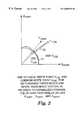
- FIG. 2is a schematic diagram of the use of local and common white references depending on colors indicated by a color imaging system
- FIG. 3is a functional block diagram of the system shown in FIG. 1;
- FIG. 4is a block diagram of a system, in accordance with the invention, for performing a color transformation
- FIG. 5is a functional block diagram of the system shown in FIG. 4 .
- the inventionprovides methods and systems for characterizing color to accurately reproduce the color from one medium or color system to another where the two systems have different illuminant and/or media white points.
- a system 10 for characterizing a color imaging systemincludes a processor 12 , a color detector 14 , a color data memory 16 , a substrate 20 , and a L + a + b + memory 28 .
- Characterizingalso commonly referred to as “profiling,” can be used to analyze a single color imaging system, or as a basis to transform the color response of a “source” color imaging system to match the color response of a “target” color imaging system.
- the color response of a color imaging systemis the correlation between a range of input color values (i.e., device stimulus data) and measured colors.
- the measured colorsare produced according to the input values for color-producing systems such as displays or printers, and are the colors measured by color-measuring systems such as scanners.
- the device stimulus datacan be, e.g., RGB or CMYK values.
- the output colorsare produced according to output values produced from the input device stimulus data. A method for characterizing a color imaging system using the system 10 will be described in terms of the functionality of system 10 .
- the processor 12executes a software application program configured to carry out the method for characterizing a color imaging system.
- the softwarecan be, e.g., in the C++ programming language.
- the processor 12can be realized, for example, by a personal computer such as an Apple MacintoshTM or an IBM PC, or by a computer workstation. Alternatively, processor 12 could be realized by a microprocessor that accesses a read-only memory (ROM) into which the application program is loaded.
- ROMread-only memory
- the application programcould be embedded in a color management software package, such as that provided with the Imation Corporation RainbowTM color proofing system, commercially available from Imation Corp., of Oakdale, Minn.
- the implementation of system 10 and the method using softwareaffords flexibility in development and modification.
- the system 10 and methodalternatively can be implemented by an integrated logic circuit for increased color processing speed.
- the color detector 14 and the color data memory 16allow the system 10 to obtain color data representing the output of various color imaging systems.
- the color datacan be obtained directly from a color imaging system via the color detector 14 , or by accessing a color data file stored in the color data memory 16 .
- the color detector 14 and the memory 16can help characterize, e.g., color printing systems, color display systems, color projection systems, and color-measuring systems.
- color detector 14is configured to measure color values of color patches 18 formed on the printing substrate 20 .
- color detector 14is configured to measure color values produced on a phosphor screen or liquid crystal matrix.
- color detector 14is equipped to measure color values of projected colors.
- color detector 14is configured to measure color valves measured by the color-measuring system.
- color detector 14could be configured to capture a scene or an animated sequence from a display or projection system, and generate color values representative of the captured imagery.
- the implementation of the color detector 14depends on the application.
- the color detector 14can be, for example, a color measurement system such as a GretagTM SPM 50 color measurement device, commercially available from Gretag, Inc., of Regensdorf, Switzerland, or a densitometer, such as an X-Rite color densitometer, commercially available from X-Rite, of Grandville, Mich.
- color detector 14can be a video camera or digital camera.
- the color detector 14can store detected data in the color data memory 16 or in the processor 12 .
- the color data obtained by color detector 14can be loaded into color data memory 16 as a color data file, as indicated by line 22 .
- the color data obtained by color detector 14can be directly loaded into a memory (not shown) associated with processor 12 , as indicated by line 24 .
- the processor 12can access its own memory or the color data file stored in color data memory 16 , as indicated by line 26 , to obtain original color data previously detected by color detector 14 .
- the color data memory 16can store several color data files for a variety of different color imaging systems.
- a system usercan direct processor 12 , via a user interface 27 (e.g., a keyboard, a mouse, or a touch-sensitive screen), to select one of the various color data files for purposes of characterizing a particular color imaging system of interest to the system user.
- a user interface 27e.g., a keyboard, a mouse, or a touch-sensitive screen
- the color data obtained from either color detector 14 or color data memory 16preferably represents CIE XYZ tristimulus values for each of a variety of color outputs generated by a color imaging system under study.
- the color datacan be converted to CIE XYZ tristimulus values.
- the CIE XYZ tristimulus valuesrepresent the relative amounts of primary color stimuli required to match colors within a CIE color system.
- the relative values of XYZare influenced by the power distribution of the illuminant, e.g., D 50 , and the CIE Standard Observer function, e.g., 2° or 10°.
- the color datacan be, for example, in the form of RGB data, CMYK density data, or other device dependent data.
- the color datapreferably represents color outputs distributed across the color gamut of the color imaging system to provide a broad sampling for purposes of color characterization.
- color patches 18represent various combinations and gradations of colors formed by dye transfer or ink deposition.
- processor 12converts the original color data using a color appearance model that uses a Y-reference and a white reference vector that depend on the intensities and neutralities of the original color data.
- the processor 12varies the conversion of a Y value of the original color data to a luminance descriptor according the Y-reference value.
- the Y-reference valuedepends on the Y value of the original color data.
- the processor 12varies the conversion of the original color data to two chrominance descriptors by determining a white reference vector according to the neutralities of colors indicated by the tristimulus values.
- white reference vectorrefers to a vector of tristimulus values X r , Y r , Z r that describe a color used as a white reference.
- the values of the Y-reference and the white reference vectorare determined according to values of a “local white point” C LW and a “common white point” C CW .
- C LW(X LW , Y LW , Z LW )
- C CW(X CW , Y CW , Z CW ).
- values of the local white point C LWare used when the original color data indicates a near-neutral color
- values of the common white point C CWare used when the original color data indicates a non-neutral, i.e., saturated, color.
- Line 29where proportions of X norm , Y norm , and Z norm are equal, indicates neutral colors.
- the quantities X norm , Y norm , and Z normare the original color data normalized by reference white values such as from a perfectly white diffuser under standard viewing conditions.
- reference white valuessuch as from a perfectly white diffuser under standard viewing conditions.
- the transition between use of the two white pointsis gradual, and not as abrupt as shown.
- the values of the vectors C LW and C CWdepend on whether the device under consideration is absorptive (e.g., paper) or emissive (e.g., a monitor), and whether relative calorimetric intent or absolute calorimetric intent is selected, e.g., through the user interface 27 .
- the local white point C LW and the common white point C CWare equal to “media white,” or “illuminant white,” or a predetermined white that may be independent of the color imaging system under consideration.
- Media white for an absorptive mediumis the white point of the absorptive substrate under a chosen illuminant.
- media whiteis the whitest color that the device produces.
- Illuminant whiteis the color reflected by a perfectly diffuse white reflector illuminated by a selected illuminant.
- TABLES 1-4illustrate the values of the local white point C LW and the common white point C CW for relative and absolute calorimetric intent for producing images using various combinations of absorptive and emissive media.
- the local white point C LW for absolute colorimetry for two absorptive devices using different illuminantsis the illuminant white corresponding to the illuminant used with each device.
- the common white point C CW for the case shown in TABLE 2is the illuminant white of either medium, or another illuminant white, as long as the same white point is used for both media.
- the local white point for absolute colorimetryis the media white for each device.
- the common white point shown in TABLE 4can be a predetermined illuminant white, which may correspond to the media white of either emissive device.
- the local white point C LW for an emissive device using absolute colorimetric intentis the media white of the emissive device.
- absolute colorimetric intent using two emissive devicesmerges with relative calorimetric intent because the media white point is used as the local white point for both rendering intents. It was discovered that when attempting to reproduce a color from an absorptive device on an emissive device using absolute colorimetry, the monitor produced a dark, overly-yellow color. It was found that the human eye adjusts to define the media white of an emissive device as being white.
- the emissive devicecan provide a good reproduction of the media white of the absorptive device and can provide good grey balance.
- the inventionaccounts for this finding by using the media white point for the local white point C LW for absolute calorimetric intent using emissive devices, thereby improving color match compared to prior techniques.
- Processor 12is adapted to alter the color appearance model dependent on the neutralities and intensities indicated by the original color data to produce a modified L*a*b* color space, an L + a + b + color space.
- Processor 12can store the L + a + b + color data in an L + a + b + memory 28 , as indicated by line 30 , in association with corresponding device stimulus data D.
- the L + a + b + color data based on color intensity and neutralityallow system 10 to achieve accurate color characterization over the entire range of a color imaging system. In particular, these data help ensure that system 10 can achieve substantial uniformity of the color characterization between light color shades and more intense colors, and between neutral and non-neutral colors.
- the processor 12can convert the original color data obtained from either color detector 14 or color data memory 16 to converted color data. To do so, the processor 12 uses any of the existing color appearance models, such as CIELAB, CIECAM-97s, RLAB, etc., subject to determination dependent on the intensities and neutralities of colors indicated by the original color data.
- CIELAB color appearance modelwill be used in the following description for purposes of illustration.
- Color dataare obtained for a particular color imaging system by either detecting color data produced by the color imaging system, as indicated by block 40 , or accessing color data in a color data file, as indicated by block 42 .
- the color datahave corresponding device stimulus data D used to actuate the color imaging system to produce a color corresponding to the color data for color-producing systems, and determined by measuring colors for color-measuring systems.
- the data indicated by block 44comprise an array of device stimulus data D 0 -D m and CIE XYZ data [(X 0 , Y 0 ,Z 0 ) . . . (X m , Y m , Z m )].
- the local white point C LW and the common white point C CWare also obtained.
- the media white point(s)is (are) obtained from the data in block 44 .
- the illuminant white reference vector(s)is (are) obtained either by accessing a data file, as indicated by block 45 , or by being provided as indicated by block 46 from an appropriate device, e.g., the processor 12 , the color detector 14 , or the user interface 27 .
- These illuminant white reference vectorscorrespond to the illuminant white points indicated in TABLES 1-4 and discussed above. These vectors correspond to the illuminant white of, e.g., the illuminant under which colors were viewed to produce the data array in block 44 , or another similar block of data, or a predetermined illuminant white point.
- the color data indicated by block 44are used to determine a white reference vector (X r ′, Y r ′, Z r ′) and a Y-reference Y r ′′ in relation to the local white point and the common white point, as indicated by block 48 .
- the white reference vector (X r ′, Y r ′, Z r ′) and the Y-reference Y r ′′are determined for each set of color data shown in block 44 according to the intensity and neutrality of the color indicated by the color data.
- the Y-reference Y r ′′ and the white reference vectorare output for further use.
- the white reference vector (X r ′, Y r ′, Z r ′) and Y-reference Y r ′′are used to determine the L + a + b + color space by converting the original color data from block 44 according to the following color appearance model equations:
- L +116 ⁇ f ⁇ ( Y / Y r ′′ ) - 16 [15]
- a +500 ⁇ [ f ⁇ ( X / X r ′ ) - f ⁇ ( Y / Y r ′ ] [16]
- b +200 ⁇ [ f ⁇ ( Y / Y r ′ ) - f ⁇ ( Z / Z r ′ ) ] [17]
- Equations [15]-[17]Applying equations [15]-[17] to the color data obtained for the color imaging system, in combination with determining the white reference vector (X r ′, Y r ′, Z r ′) and Y-reference Y r ′′ as in equations [6]-[14], produces a set of L + a + b + color space data that characterizes the color response of the color imaging system.
- the L + a + b + color space dataare stored in an array as indicated by block 54 .
- the lightness value L +depends on the Y values of the color data in block 44 and of the local white point and common white point. Equations [6]-[7] and [15] indicate that as the value of Y in the original color data from block 44 increases, corresponding to a lighter color, the Y-reference Y r ′′ approaches the Y value for local white. As the value of Y decreases, corresponding to a darker color, the Y-reference Y r ′′ approaches the Y value for common white.
- the redness-greenness value a + and the yellowness-blueness value b +depend on the X, Y, and Z values of the original color data in block 44 and of the local white point and common white point. Equations [8]-[14] and [16]-[17] indicate that as the color indicated by a set of original color data X,Y,Z, approaches a neutral color, the white reference vector (X r ′, Y r ′, Z r ′) approaches the local white point C LW . As the color indicated by the set of color data deviates from a neutral color, the white reference vector (X r ′, Y r ′, Z r ′) approaches the common white point C CW .
- the more neutral the color indicated by the set of original color data from block 44the more the redness-greenness value a + and the yellowness-blueness b + value depend on the local white point as a reference white point and the more saturated the color, the more the a + and b + values depend on the common white point as a reference white point.
- a system 32 for performing a color transformationincludes a processor 12 , a color detector 14 , a color data memory 16 , a first substrate 20 , a second substrate 38 , and a stored color transformation table 34 .
- the components of system 32substantially correspond to system 10 of FIG. 1, with similar features having identical reference numbers.
- System 32performs similar functions to those of system 10 to characterize two or more different color imaging systems.
- System 32calculates a mapping between the color imaging systems based on the characterizations. The mapping is used to generate the color transformation table 34 , which is stored in memory by the processor 12 as indicated by line 36 .
- the color transformation table 34is used to produce a color on a target color imaging system that visually matches the color produced by a source color imaging system.
- the color detector 14is configured to obtain color data representing the output of two or more color imaging systems. As shown in FIG. 4, color detector 14 is configured to detect color data from color patches 18 formed on the first printing substrate 20 by, or provided to, a first color imaging system and color patches (not shown) formed on the second printing substrate 38 by, or provided to, a second color imaging system. Alternatively, detector 14 can be configured to measure color values produced by various emissive or projecting devices, such as by phosphor screens or liquid crystal matrices. The detector 14 can send the detected color data to the color data memory 16 along line 22 for storage or to the processor 12 along line 24 for storage or processing.
- the color data memory 16stores color data in one or more color data files.
- the color datacan be received from the detector 14 or from another source.
- the color data memory 16can transmit stored color data to the processor 12 along line 26 .
- the processor 12is configured to receive color data from the detector 14 and/or the memory 16 and to process the received data to perform a color transformation.
- the color data detected by the detector 14 and/or stored in color data memory 16preferably represents CIE XYZ tristimulus values for each of a variety of color outputs generated by the different color imaging systems.
- processor 12can convert the color data obtained for each of the different color imaging systems using the L + a + b + color appearance model.
- the processor 12can convert original color data obtained for the first and second color imaging systems into L + a + b + data.
- the conversionuses white reference vectors and Y-reference values that vary between local white and common white values of each color imaging system.
- the Y-reference values and white reference vectorsdepend on the intensities and neutralities of the colors indicated by the original color data from each color imaging system.
- FIG. 5illustrates the functionality of system 32 and a method for performing a color transformation.
- Color dataare obtained for a first, or source, color imaging system, as indicated by block 56 , and for a second, or target, color imaging system, as indicated by block 58 .
- the resulting color data for the first color imaging systemcomprises an array of CIE XYZ data [(X 0,1 , Y 0,1 , Z 0,1 ) . . . (X m,1 , Y m,1 , Z m,1 ,)], whereas the color data for the second color imaging system comprises an array of CIE XYZ color data [(X 0,2 , Y 0,2 , Z 0,2 ) . . .
- the vector (X 0,1 , Y 0,1 , Z 0,1 )represents the color data obtained for the media white point associated with the first, absorptive (e.g., CMYK), color imaging system
- the vector (X 0,2 , Y 0,2 , Z 0,2 )represents the color data obtained for the media white point associated with the, absorptive, second color imaging system.
- these vectorscan represent the media black points for emissive systems such as RGB systems.
- the vector (X m,1 , Y m,1 , Z m,1 ,)represents the color data obtained for a maximum (minimum) intensity color produced by the first absorptive (emissive) color imaging system
- the vector (X m,2 , Y m,2 , Z m,2 )represents the color data obtained for a maximum (minimum) intensity color produced by the second absorptive (emissive) color imaging system.
- the value of X m,1is given by the value of X 1 which satisfies:
- Local white points C LW1 and C LW2 and the common white point C CWare obtained from the appropriate media and illuminant white points (TABLES 1-4).
- the media white pointsare obtained from the data in blocks 56 and 58 and the illuminant white point(s) is(are) obtained by accessing stored data (block 59 ) or by being provided (block 60 ) as appropriate.
- the illuminant white pointscorrespond to, e.g., the illuminant under which colors were viewed to produce the data in blocks 56 and 58 , or a predetermined white point.
- the color data in blocks 56 and 58are used to determine white reference vectors (X r1 ′, Y r1 ′, Z r1 ′) and (X r2 ′, Y r2 ′, Z r2 ′) and Y-stimuli Y r1 ′′ and Y r2 ′′ in relation to local white points C LW1 and C LW2 and the common white point C CW .
- the values for Y-stimuli Y r1 ′′ and Y r2 ′′ and for white reference vectors (X r1 ′, Y r1 ′, Z r1 ′) and (X r2 ′, Y r2 ′, Z r2 ′)are output for further use.
- the complete sets of L 1 + a 1 + b 1 + and L 2 + a 2 + b 2 + color space dataare mapped to each other by the processor 12 as indicated by block 74 .
- the processor 12maps the color space data from the two color imaging systems to each other. This also maps the device stimulus data corresponding to the color space data for each color imaging system to each other. Thus, a mapping between device stimulus data (e.g., CMYK to C′M′Y′K′ or RGB to CMYK) for the two color imaging systems is produced. Using this mapping, once the stimulus data associated with one color imaging system when producing, or measuring as the case may be, a color are known, the other system can be actuated with the mapped stimulus data to reproduce the color. The mapping is stored in a color transformation table as indicated by block 76 .
- color datacan be obtained in manners other than those described.
- Color appearance modelsthat employ a luminance descriptor and descriptors for the relative amounts of red, green, yellow, and blue, other than those mentioned, can be used.
- the XYZ tristimulus valueswere described above as having, e.g., 256 discrete values (e.g., for a digital system), they may take on values for an analog system over a broad range of values to characterize, e.g., paint samples.
- Appendix Aprovides an example, which in no way limits the scope of the invention or the appended claims, of C++ code utilizing the tangent of the angle from neutral.
- the code in Appendix Acould be modified to use the angle, or the sine of the angle from neutral.
- L + a + b + valuesand the local white point C LW and the common white point C CW are possible.
- the relationship between the white reference vector (X r ′, Y r ′, Z r ′) and the Y-reference and the local white point C LW and the common white point C CWwas exemplary only and other relationships are possible.
- the L + a + b + color spacecan be determined according to the following equations.
- the Bradford chromatic adaptation transformcan be modified to scale white points when using absolute white points instead of normalized white points such as for media-relative mapping of reflective prints. It is useful to think in terms of reference conditions (the destination conditions) and local conditions (the source conditions). For example, in the case of a reflection print, the white point for the reference conditions is usually the reference illuminant (e.g., D50), and the white point for the local condition is the media white.
- the reference illuminante.g., D50
- X l , Y l , and Z lare the tristimulus values of a color to be transformed
- R l , G l , and B lare the modified responses of the cones of the human eye.
- the RGB signalsare chromatically adapted from the local condition to the reference condition using the following equations (assuming complete adaptation):
- R ref( R rw /R lw ) ⁇ R l
- G ref( G rw /G lw ) ⁇ G l
- B refSign[ B l ] ⁇ ( B rw /B lw ⁇ ) ⁇
- R rw , G rw , and B rware the reference white RGB values
- R lw , G lw , and B lware the local white RGB values
- This adaptation to the reference conditiontakes into account any differences between the absolute level of the reference and local white luminance, in addition to factoring in the local black point.
- this adaptation methodcan be used for media-relative proofing to map between reflection prints. In this application, it is undesirable to simulate the absolute white point by printing color in the background area of the proof.
- the local white to local black (neutral) axisis mapped to the neutral axis of the reference condition, while larger adaptations are applied to colors that are further away from the local neutral axis.
- thiscan be viewed as an alternative approach to the variable white reference concepts discussed above.
- This chromatic adaptation formulationcan use color spaces other than the standard L + a + b + color space. This formulation can just as easily be used with alternative color spaces such as the ones from CIECAM-97s, LLab, or RLab. By utilizing the same XYZ to “uniform color space” transformation for all components of a given matching step, however, different adaptation methods can be applied to achieve useful results, as discussed below.
- [L rw , M rw , S rw ]are the LMS (long, medium, and short wavelength band) values of the reference white
- [L lw , M lw , S lw ]are the LMS values for local white
- [L lk , M lk , S lk ]are the LMS values for the local black.
- the resulting adapted XYZ valueis used as the starting point for computing the L*a*b* value using the XYZ to Lab equations described above.
- XYZ rwis the XYZ of the reference illuminant for both print devices, assuming a common illuminant.
- XYZ lw for each of the printsis the actual XYZ of the media white of the respective print.
- the illuminant whitewill be common for the two prints and will reflect the desired viewing environment (e.g., a D 50 light booth).
- White on the first printwill map to white on the second print, and differences in the background paper color will be taken into account in generating the match for chromatic colors.
- XYZ rwis the XYZ of the reference illuminant.
- XYZ lw for the printis the actual XYZ of the media white of the print.
- XYZ lw for the displayis the actual XYZ of the monitor white point of the display.
- the monitor colorswill be chromatically adapted to the reference illuminant so as to give a good perceptual match.
- the white point of the printwill map to the white point of the monitor.
- XYZ rwis the XYZ of the reference illuminant.
- XYZ lw for the printis the actual XYZ of the media white of the print.
- XYZ lw for the displayis the actual XYZ of the monitor white point of the display.
- the Bradford-type adaptation performed on the monitor valuessimulates the chromatic adaptation occurring in the eye.
- Absolute colorimetry, performing no chromatic adaptationcan be used on the print while performing the chromatic adaptation on the monitor to achieve a good perceptual match.
- This approachcould be applied using a different conversion between XYZ values and the matching color metric (e.g., L*a*b*, LLab, RLab, CIECAM-97s).
Landscapes
- Engineering & Computer Science (AREA)
- Multimedia (AREA)
- Signal Processing (AREA)
- Color Image Communication Systems (AREA)
- Facsimile Image Signal Circuits (AREA)
- Image Processing (AREA)
- Processing Of Color Television Signals (AREA)
Abstract
Description


| TABLE 1 |
| Reference White Points for Two Absorptive Devices |
| Using One Illuminant |
| Relative Colorimetry | Absolute Colorimetry | ||
| Local White | media white | illuminant white |
| Point | ||
| Common White | illuminant white | illuminant white |
| Point | ||
| TABLE 2 |
| Reference White Points for Two Absorptive Devices Using |
| Different Illuminants |
| Relative Color | Absolute Colorimetry | ||
| Local White | media white | illuminant white |
| Point | (for each device) | |
| Common White | illuminant white | illuminant white |
| Point | ||
| TABLE 3 |
| Reference White Points for One Absorptive Device |
| and One Emissive Device |
| Relative Colorimetry | Absolute Colorimetry | ||
| Local White | media white | media white (emissive) |
| Point | illuminant white | |
| (absorptive) | ||
| Common White | illuminant white | illuminant white |
| Point | ||
| TABLE 4 |
| Reference White Points for Two Emissive Devices |
| Relative Colorimetry | Absolute Colorimetry | ||
| Local White | media white | media white |
| Point | (for each device) | |
| Common White | illuminant white | illuminant white |
| Point | ||
| APPENDIX A | ||
| static const double | kOneThird | = (1.0/3.0); |
| static const double | kLabExp | = 2.8; |
| static const double | kChromaPower | = 1.5; |
| static const double | kWhiteRefCoeff | = 2.5; |
| static const double | kLabThresh | = (0.00885600); |
| static const double | kLabCbrtThresh = pow(kLabThresh, |
| kOneThird); |
| static const double kBlackPtScale = −0.0; |
| #define LabGammaThresh (gamma) pow (kLabThresh, gamma) |
| #define min2_(x,y) | (x>y ? y : x) |
| #define max2_(x,y) | (x>y ? x : y) |
| #define min3_(x,y,z) | (min2_(x,y)> z? z : min2_(x,y)) |
| #define max3_(x,y,z) | max2_(0.0001, (max2_(x,y) > z? |
| max2_(x,y) : z)) |
| void CalcLABPLUS( double X,double Y, double Z, |
| double Xm,double Ym, double Zm, | |
| double Xn,double Yn, double Zn, | |
| double *L_star, double *a_star, double | |
| *b_star) |
| { |
| double X,Y,Z,Xm,Ym,Zm,Xn,Yn,YnL,Zn,Xr,Yr,Zr,cbrtY; |
| double ratX, ratY, ratZ; |
| double POWER_XYZ = 1.0/kLabExp; |
| static const double LAB_THRESH = ((double) 0.00885600); |
| static const double LAB_CONST = ((double) 0.13793103); |
| double Lscale = (116.0*pow(LAB_THRESH,POWER_XYZ) - |
| 16.0)/LAB_THRESH; |
| double XYZscale = (pow(LAB_THRESH,POWER_XYZ) - |
| LAB_CONST)/LAB_THRESH; |
| double deltaWhitePtX = Xm − Xn; |
| double deltaWhitePtY = Ym − Yn; |
| double deltaWhitePtZ = Zm − Zn; |
| double Xnorm = X/Xm; |
| double Ynorm = Y/Ym; |
| double Znorm = Z/Zm; |
| double XYZlength = |
| sqrt (Xnorm*Xnorm+Ynorm*Ynorm+Znorm*Znorm); |
| double XYZDiagProjection = (Xnorm+Ynorm+Znorm)/sqrt(3.0); |
| double devXYZ = sqrt(XYZlength*XYZlength- |
| XYZDiagProjection*XYZDiagProjection); |
| double maxDev = 2.0 * sqrt(3.0)/3.0; |
| devTangentXYZ = devXYZ/XYZDiagProjection; |
| whiteRefCorr = kWhiteRefCoeff * |
| pow(devTangentXYZ/maxDev, kChromaPower); |
| double XAdj −= X − Xnorm * deltaWhitePtX * (1.0 − devXYZ); |
| double YAdj −= Y − Ynorm * deltaWhitePtY * (1.0 − devXYZ); |
| double ZAdj −= Z − Znorm * deltaWhitePtZ * (1.0 − devXYZ); |
| doubleXbm = Xm * kBlackPtScale; |
| doubleYbm = Ym * kBlackPtScale; |
| doubleZbm = Zm * kBlackPtScale; |
| Xn = (X/XAdj) * Xn; |
| Yn = (Y/YAdj) * Yn; |
| Zn = (Z/ZAdj) * Zn; |
| Xr = X/Xn; |
| Yr = Y/Yn; |
| Zr = Z/Zn; |
| cbrtY = pow(Yr, POWER_XYZ); |
| 116.0*cbrtY − 16.0 : 903.3*Yr); |
| cbrtY = pow(Yr, POWER_XYZ); |
| cbrtY = (Yr > LAB_THRESH) ? cbrtY : XYZscale*Yr + LAB_CONST; |
| *a_star = 500.0 *(((Xr > LAB_THRESH) ? pow(Xr, POWER_XYZ) : |
| XYZscale*Xr + LAB_CONST) − cbrtY); |
| *b_star = 200.0 *(cbrtY − ((Zr > LAB_THRESH) ? pow(Zr, |
| POWER_XYZ) : XYZscale*Zr + LAB_CONST)); |
| Yr = Y/Ym; |
| cbrtY = pow(Yr, POWER_XYZ); |
| *L_Star = ((Yr>LAB_THRESH)?116.0*cbrtY−16.0: Lscale*Yr); |
| return; |
| } |
Claims (17)


Priority Applications (6)
| Application Number | Priority Date | Filing Date | Title |
|---|---|---|---|
| US09/259,579US6608925B1 (en) | 1999-03-01 | 1999-03-01 | Color processing |
| DE69928835TDE69928835T2 (en) | 1999-03-01 | 1999-09-23 | COLOR PROCESSING |
| EP99948353AEP1157542B1 (en) | 1999-03-01 | 1999-09-23 | Color processing |
| PCT/US1999/021784WO2000052924A1 (en) | 1999-03-01 | 1999-09-23 | Color processing |
| JP2000603236AJP4620252B2 (en) | 1999-03-01 | 1999-09-23 | Color processing |
| US10/612,734US7120295B2 (en) | 1999-03-01 | 2003-07-02 | Color processing |
Applications Claiming Priority (1)
| Application Number | Priority Date | Filing Date | Title |
|---|---|---|---|
| US09/259,579US6608925B1 (en) | 1999-03-01 | 1999-03-01 | Color processing |
Related Child Applications (1)
| Application Number | Title | Priority Date | Filing Date |
|---|---|---|---|
| US10/612,734DivisionUS7120295B2 (en) | 1999-03-01 | 2003-07-02 | Color processing |
Publications (1)
| Publication Number | Publication Date |
|---|---|
| US6608925B1true US6608925B1 (en) | 2003-08-19 |
Family
ID=22985501
Family Applications (2)
| Application Number | Title | Priority Date | Filing Date |
|---|---|---|---|
| US09/259,579Expired - Fee RelatedUS6608925B1 (en) | 1999-03-01 | 1999-03-01 | Color processing |
| US10/612,734Expired - LifetimeUS7120295B2 (en) | 1999-03-01 | 2003-07-02 | Color processing |
Family Applications After (1)
| Application Number | Title | Priority Date | Filing Date |
|---|---|---|---|
| US10/612,734Expired - LifetimeUS7120295B2 (en) | 1999-03-01 | 2003-07-02 | Color processing |
Country Status (5)
| Country | Link |
|---|---|
| US (2) | US6608925B1 (en) |
| EP (1) | EP1157542B1 (en) |
| JP (1) | JP4620252B2 (en) |
| DE (1) | DE69928835T2 (en) |
| WO (1) | WO2000052924A1 (en) |
Cited By (14)
| Publication number | Priority date | Publication date | Assignee | Title |
|---|---|---|---|---|
| US20020021833A1 (en)* | 2000-07-25 | 2002-02-21 | Manabu Ohga | Image processing apparatus and method |
| US20030063303A1 (en)* | 2001-09-27 | 2003-04-03 | Fuji Photo Film Co., Ltd. | Image processor, image processing method and program for executing the method |
| US20040218811A1 (en)* | 1999-03-01 | 2004-11-04 | Kodak Polychrome Graphics | Color processing |
| US20050249402A1 (en)* | 2004-05-05 | 2005-11-10 | Canon Kabushiki Kaisha | Characterization of display devices by averaging chromaticity values |
| US7057765B1 (en)* | 1999-05-28 | 2006-06-06 | Eastman Kodak Company | Constrained multi-dimensional color transformation |
| US20060181722A1 (en)* | 2005-02-15 | 2006-08-17 | Eastman Kodak Company | System and method for profiling digital-image input devices |
| US20060232771A1 (en)* | 2005-04-15 | 2006-10-19 | Xerox Corporation | Gray balance calibration of an imaging system |
| US7230737B1 (en)* | 1999-09-17 | 2007-06-12 | Canon Kabushiki Kaisha | Image processing method and apparatus |
| US20070216776A1 (en)* | 2006-03-14 | 2007-09-20 | Xerox Corporation | Color image reproduction |
| US20090141973A1 (en)* | 2005-12-01 | 2009-06-04 | Wallack Aaron S | Method of pattern location using color image data |
| US20090153888A1 (en)* | 2007-12-18 | 2009-06-18 | Edge Christopher J | Method and apparatus for chromatic adaptation |
| US20100053381A1 (en)* | 2008-09-01 | 2010-03-04 | Canon Kabushiki Kaisha | Image processing apparatus and method thereof |
| US20100054589A1 (en)* | 2008-09-01 | 2010-03-04 | Canon Kabushiki Kaisha | Color processing apparatus and method thereof |
| US20110033106A1 (en)* | 2004-09-23 | 2011-02-10 | Mitsubishi Denki Kabushiki Kaisha | Methods of representing and analysing images |
Families Citing this family (18)
| Publication number | Priority date | Publication date | Assignee | Title |
|---|---|---|---|---|
| JP3984852B2 (en)* | 2002-04-02 | 2007-10-03 | キヤノン株式会社 | Color processing apparatus and method |
| JP2005208817A (en)* | 2004-01-21 | 2005-08-04 | Konica Minolta Photo Imaging Inc | Image processing method, image processor, and image recording device |
| JP4343752B2 (en)* | 2004-03-31 | 2009-10-14 | キヤノン株式会社 | Color processing apparatus and method |
| JP4721398B2 (en)* | 2004-03-31 | 2011-07-13 | キヤノン株式会社 | Color processing apparatus and method |
| US7301543B2 (en)* | 2004-04-09 | 2007-11-27 | Clairvoyante, Inc. | Systems and methods for selecting a white point for image displays |
| US7715044B2 (en)* | 2005-03-29 | 2010-05-11 | Xerox Corporation | Two-dimensional gray component replacement |
| US7724981B2 (en)* | 2005-07-21 | 2010-05-25 | Ancestry.Com Operations Inc. | Adaptive contrast control systems and methods |
| US7684080B2 (en)* | 2006-06-07 | 2010-03-23 | Adobe Systems Incorporated | Accommodating creative white point |
| WO2008044732A1 (en)* | 2006-10-11 | 2008-04-17 | Nikon Corporation | Image processing device, image processing method, and image processing program |
| WO2008062874A1 (en)* | 2006-11-22 | 2008-05-29 | Nikon Corporation | Image processing method, image processing program, image processing device and camera |
| US7971208B2 (en) | 2006-12-01 | 2011-06-28 | Microsoft Corporation | Developing layered platform components |
| JP4623137B2 (en)* | 2008-05-14 | 2011-02-02 | 富士ゼロックス株式会社 | Color processing apparatus, method and program |
| US8401289B2 (en)* | 2009-07-31 | 2013-03-19 | Eastman Kodak Company | Method for matching colors between two systems |
| US8427722B2 (en)* | 2010-06-04 | 2013-04-23 | Eastman Kodak Company | Color transform insensitive to process variability |
| KR20120014804A (en) | 2010-08-10 | 2012-02-20 | 삼성전자주식회사 | Video signal generating device and method for reducing crosstalk between brightness signal and color difference signal |
| CN105637534A (en)* | 2013-09-20 | 2016-06-01 | A2Z罗基克斯公司 | System and method for reducing visible artifacts in the display of compressed and decompressed digital images and video |
| US8836716B1 (en) | 2013-09-20 | 2014-09-16 | Spinella Ip Holdings, Inc. | System and method for reducing visible artifacts in the display of compressed and decompressed digital images and video |
| KR102710736B1 (en) | 2022-09-06 | 2024-09-27 | 삼성전자주식회사 | A method for deriving the color response characteristics of an image acquisition device |
Citations (8)
| Publication number | Priority date | Publication date | Assignee | Title |
|---|---|---|---|---|
| US4500919A (en) | 1982-05-04 | 1985-02-19 | Massachusetts Institute Of Technology | Color reproduction system |
| US4992963A (en) | 1988-12-02 | 1991-02-12 | Simon Fraser University | Method and apparatus for determining ambient light and surface reflectance |
| EP0753725A2 (en) | 1995-07-12 | 1997-01-15 | Minnesota Mining And Manufacturing Company | System and method for color characterization and transformation |
| US5668890A (en)* | 1992-04-06 | 1997-09-16 | Linotype-Hell Ag | Method and apparatus for the automatic analysis of density range, color cast, and gradation of image originals on the BaSis of image values transformed from a first color space into a second color space |
| US5786823A (en) | 1993-05-07 | 1998-07-28 | Eastman Kodak Company | Method and apparatus employing composite transforms of intermediary image data metrics for achieving imaging device/media compatibility and color appearance matching |
| EP0948194A2 (en) | 1998-03-30 | 1999-10-06 | Seiko Epson Corporation | Device-independent and medium-independent color matching between an input device and an output device |
| US6108442A (en)* | 1997-06-27 | 2000-08-22 | Minnesota Mining And Manufacturing Company | Characterization of color imaging systems |
| US6373531B1 (en)* | 1995-10-05 | 2002-04-16 | Canon Kabushiki Kaisha | Image processing apparatus, method, and recording medium for performing color correction suitable for matching ambient light for different types of output devices |
Family Cites Families (4)
| Publication number | Priority date | Publication date | Assignee | Title |
|---|---|---|---|---|
| JP3635673B2 (en)* | 1994-02-07 | 2005-04-06 | ソニー株式会社 | Image processing method and image processing apparatus |
| US6362808B1 (en)* | 1997-07-03 | 2002-03-26 | Minnesota Mining And Manufacturing Company | Arrangement for mapping colors between imaging systems and method therefor |
| US6480299B1 (en)* | 1997-11-25 | 2002-11-12 | University Technology Corporation | Color printer characterization using optimization theory and neural networks |
| US6608925B1 (en) | 1999-03-01 | 2003-08-19 | Kodak Polychrome Graphics, Llc | Color processing |
- 1999
- 1999-03-01USUS09/259,579patent/US6608925B1/ennot_activeExpired - Fee Related
- 1999-09-23DEDE69928835Tpatent/DE69928835T2/ennot_activeExpired - Lifetime
- 1999-09-23JPJP2000603236Apatent/JP4620252B2/ennot_activeExpired - Fee Related
- 1999-09-23WOPCT/US1999/021784patent/WO2000052924A1/enactiveIP Right Grant
- 1999-09-23EPEP99948353Apatent/EP1157542B1/ennot_activeExpired - Lifetime
- 2003
- 2003-07-02USUS10/612,734patent/US7120295B2/ennot_activeExpired - Lifetime
Patent Citations (10)
| Publication number | Priority date | Publication date | Assignee | Title |
|---|---|---|---|---|
| US4500919A (en) | 1982-05-04 | 1985-02-19 | Massachusetts Institute Of Technology | Color reproduction system |
| US4992963A (en) | 1988-12-02 | 1991-02-12 | Simon Fraser University | Method and apparatus for determining ambient light and surface reflectance |
| US5668890A (en)* | 1992-04-06 | 1997-09-16 | Linotype-Hell Ag | Method and apparatus for the automatic analysis of density range, color cast, and gradation of image originals on the BaSis of image values transformed from a first color space into a second color space |
| US5786823A (en) | 1993-05-07 | 1998-07-28 | Eastman Kodak Company | Method and apparatus employing composite transforms of intermediary image data metrics for achieving imaging device/media compatibility and color appearance matching |
| US5956044A (en)* | 1993-05-07 | 1999-09-21 | Eastman Kodak Company | Imaging device to media compatibility and color appearance matching with flare, luminance, and white point comparison |
| EP0753725A2 (en) | 1995-07-12 | 1997-01-15 | Minnesota Mining And Manufacturing Company | System and method for color characterization and transformation |
| US5754448A (en)* | 1995-07-12 | 1998-05-19 | Minnesota Mining And Manufacturing Company | System and method for color characterization and transformation |
| US6373531B1 (en)* | 1995-10-05 | 2002-04-16 | Canon Kabushiki Kaisha | Image processing apparatus, method, and recording medium for performing color correction suitable for matching ambient light for different types of output devices |
| US6108442A (en)* | 1997-06-27 | 2000-08-22 | Minnesota Mining And Manufacturing Company | Characterization of color imaging systems |
| EP0948194A2 (en) | 1998-03-30 | 1999-10-06 | Seiko Epson Corporation | Device-independent and medium-independent color matching between an input device and an output device |
Non-Patent Citations (9)
| Title |
|---|
| Dr. Edward Granger; Light Source, Inc.; A New Color Space for Image Appearance Equivalence; Seybold Seminars 1992; Abridged Conference Proceedings, pp. 47-48. |
| Gunter Wyszecki et al.; Color Science, Concepts and Methods, Quantitative Data and Formulae, 2nd Edition; John Wiley & Sons. |
| International Color Profile Format; version 3.0, Jun. 10, 1994. |
| Jonathan Seybold et al,; Color and Imaging; Seybold Seminars 1992; Abridged Conference Proceedings; pp. 33-36. |
| Mark D. Fairchild et al,; Image Color-Appearance Specification Through Extension of CIELAB; 1993, John Wiley & Sons, Inc., pp. 178-190. |
| Mark D. Fairchild; Visual Evaluation and Evolution of the RLAB Color Space; Munsell Color Science Laboratory, Center for Imaging Science Rochester Institute of Technology, Rochester, New York; 1994. |
| Maureen C. Stone et al.; Color Gamut Mapping and the Printing of Digital Color Images; ACM Transactions on Graphics, vol. 7, No. 4, Oct. 1988, pp. 249-292. |
| Michael R. Pointer et al.; A Color Reproduction Index; 1994. |
| R.W.G. Hunt, Revised Colour-Appearance Model for Related and Unrelated Colours; 1991, John Wiley & Sons, Inc.; pp. 146-165. |
Cited By (31)
| Publication number | Priority date | Publication date | Assignee | Title |
|---|---|---|---|---|
| US20040218811A1 (en)* | 1999-03-01 | 2004-11-04 | Kodak Polychrome Graphics | Color processing |
| US7120295B2 (en) | 1999-03-01 | 2006-10-10 | Eastman Kodak Company | Color processing |
| US7057765B1 (en)* | 1999-05-28 | 2006-06-06 | Eastman Kodak Company | Constrained multi-dimensional color transformation |
| US7230737B1 (en)* | 1999-09-17 | 2007-06-12 | Canon Kabushiki Kaisha | Image processing method and apparatus |
| US7295705B2 (en) | 2000-07-25 | 2007-11-13 | Canon Kabushiki Kaisha | Image processing apparatus and method |
| US6850640B2 (en)* | 2000-07-25 | 2005-02-01 | Canon Kabushiki Kaisha | Image processing apparatus and method |
| US20050094874A1 (en)* | 2000-07-25 | 2005-05-05 | Canon Kabushiki Kaisha | Image processing apparatus and method |
| US7599553B2 (en) | 2000-07-25 | 2009-10-06 | Canon Kabushiki Kaisha | Image processing apparatus and method that perform color matching using detected uniformity |
| US20020021833A1 (en)* | 2000-07-25 | 2002-02-21 | Manabu Ohga | Image processing apparatus and method |
| US20080025601A1 (en)* | 2000-07-25 | 2008-01-31 | Canon Kabkushiki Kaisha | Image processing apparatus and method |
| US20030063303A1 (en)* | 2001-09-27 | 2003-04-03 | Fuji Photo Film Co., Ltd. | Image processor, image processing method and program for executing the method |
| US7312892B2 (en)* | 2001-09-27 | 2007-12-25 | Fujifilm Corporation | Image processing apparatus, method, and program performing chromatic and achromatic data conversion for a preferred whiteness in an image output |
| US7085414B2 (en) | 2004-05-05 | 2006-08-01 | Canon Kabushiki Kaisha | Characterization of display devices by averaging chromaticity values |
| US20050249402A1 (en)* | 2004-05-05 | 2005-11-10 | Canon Kabushiki Kaisha | Characterization of display devices by averaging chromaticity values |
| US8306334B2 (en)* | 2004-09-23 | 2012-11-06 | Mitsubishi Denki Kabushiki Kaisha | Methods of representing and analysing images |
| US20110033106A1 (en)* | 2004-09-23 | 2011-02-10 | Mitsubishi Denki Kabushiki Kaisha | Methods of representing and analysing images |
| US20060181722A1 (en)* | 2005-02-15 | 2006-08-17 | Eastman Kodak Company | System and method for profiling digital-image input devices |
| US7733353B2 (en)* | 2005-02-15 | 2010-06-08 | Eastman Kodak Company | System and method for profiling digital-image input devices |
| US20090059322A1 (en)* | 2005-04-15 | 2009-03-05 | Xerox Corporation | Gray Balance Calibration of an Imaging System |
| US7733478B2 (en) | 2005-04-15 | 2010-06-08 | Xerox Corporation | Gray balance calibration of an imaging system |
| US7450226B2 (en) | 2005-04-15 | 2008-11-11 | Xerox Corporation | Gray balance calibration of an imaging system |
| US20060232771A1 (en)* | 2005-04-15 | 2006-10-19 | Xerox Corporation | Gray balance calibration of an imaging system |
| US20090141973A1 (en)* | 2005-12-01 | 2009-06-04 | Wallack Aaron S | Method of pattern location using color image data |
| US7965887B2 (en) | 2005-12-01 | 2011-06-21 | Cognex Technology And Investment Corp. | Method of pattern location using color image data |
| US20070216776A1 (en)* | 2006-03-14 | 2007-09-20 | Xerox Corporation | Color image reproduction |
| US20090153888A1 (en)* | 2007-12-18 | 2009-06-18 | Edge Christopher J | Method and apparatus for chromatic adaptation |
| US7697176B2 (en) | 2007-12-18 | 2010-04-13 | Eastman Kodak Company | Method and apparatus for chromatic adaptation |
| US20100053381A1 (en)* | 2008-09-01 | 2010-03-04 | Canon Kabushiki Kaisha | Image processing apparatus and method thereof |
| US20100054589A1 (en)* | 2008-09-01 | 2010-03-04 | Canon Kabushiki Kaisha | Color processing apparatus and method thereof |
| US8164650B2 (en)* | 2008-09-01 | 2012-04-24 | Canon Kabushiki Kaisha | Image processing apparatus and method thereof |
| US8290262B2 (en) | 2008-09-01 | 2012-10-16 | Canon Kabushiki Kaisha | Color processing apparatus and method thereof |
Also Published As
| Publication number | Publication date |
|---|---|
| WO2000052924A1 (en) | 2000-09-08 |
| US7120295B2 (en) | 2006-10-10 |
| EP1157542B1 (en) | 2005-12-07 |
| DE69928835D1 (en) | 2006-01-12 |
| US20040218811A1 (en) | 2004-11-04 |
| JP4620252B2 (en) | 2011-01-26 |
| EP1157542A1 (en) | 2001-11-28 |
| JP2002538515A (en) | 2002-11-12 |
| DE69928835T2 (en) | 2006-08-24 |
Similar Documents
| Publication | Publication Date | Title |
|---|---|---|
| US6608925B1 (en) | Color processing | |
| US5754448A (en) | System and method for color characterization and transformation | |
| US7586642B2 (en) | Color-space transformation-matrix calculating system and calculating method | |
| US5956015A (en) | Method and system for correcting color display based upon ambient light | |
| US6008907A (en) | Printer calibration | |
| US6480299B1 (en) | Color printer characterization using optimization theory and neural networks | |
| US8203756B2 (en) | Method for characterizing the color response of an imaging device | |
| US4884130A (en) | Method of describing a color in a triaxial planar vector color space | |
| EP0991924B1 (en) | Characterization of color imaging systems | |
| US8223336B2 (en) | Method for converting digital color images | |
| US8401289B2 (en) | Method for matching colors between two systems | |
| US8355573B2 (en) | Method for matching colors by using human observer color matching functions | |
| US20030020727A1 (en) | Reducing metamerism in color management systems | |
| US8358318B2 (en) | Method for reproducing an image on an imaging device | |
| JP2006500877A (en) | Digital image color correction method | |
| US7791760B2 (en) | Recording-medium profile correction to achieve color matching | |
| US8203712B2 (en) | Method and apparatus for measuring colors | |
| JP2012044475A (en) | Image processing method and image output device | |
| JPH09219800A (en) | Color image processing equipment | |
| Angelov et al. | Color Errors Generated Due to Color Space Transformation | |
| Moroney | CIECAM02 | |
| Ramamurthy et al. | Achieving color match between scanner, monitor, and film: A color management implementation for feature animation | |
| WO2000054213A1 (en) | System for color balancing animations and the like | |
| Kuo | A Study of effect of CRT gamma and white point on softcopy and hardcopy agreement | |
| Williamson | A colorimetric investigation of soft proofing |
Legal Events
| Date | Code | Title | Description |
|---|---|---|---|
| AS | Assignment | Owner name:IMATION CORP., MINNESOTA Free format text:ASSIGNMENT OF ASSIGNORS INTEREST;ASSIGNORS:EDGE, CHRISTOPHER J.;ROZZI, WILLIAM A.;FISCHER, TIMOTHY A.;REEL/FRAME:009977/0334 Effective date:19990423 | |
| AS | Assignment | Owner name:KODAK POLYCHROME GRAPHICS, CONNECTICUT Free format text:ASSIGNMENT OF ASSIGNORS INTEREST;ASSIGNOR:IMATION CORP.;REEL/FRAME:013090/0381 Effective date:20020910 | |
| FEPP | Fee payment procedure | Free format text:PAYER NUMBER DE-ASSIGNED (ORIGINAL EVENT CODE: RMPN); ENTITY STATUS OF PATENT OWNER: LARGE ENTITY Free format text:PAYOR NUMBER ASSIGNED (ORIGINAL EVENT CODE: ASPN); ENTITY STATUS OF PATENT OWNER: LARGE ENTITY | |
| AS | Assignment | Owner name:EASTMAN KODAK COMPANY, NEW YORK Free format text:MERGER;ASSIGNOR:KPG HOLDING COMPANY, INC. (FORMERLY KODAK POLYCHROME GRAPHICS LLC);REEL/FRAME:018075/0987 Effective date:20060619 | |
| FPAY | Fee payment | Year of fee payment:4 | |
| FPAY | Fee payment | Year of fee payment:8 | |
| AS | Assignment | Owner name:CITICORP NORTH AMERICA, INC., AS AGENT, NEW YORK Free format text:SECURITY INTEREST;ASSIGNORS:EASTMAN KODAK COMPANY;PAKON, INC.;REEL/FRAME:028201/0420 Effective date:20120215 | |
| AS | Assignment | Owner name:WILMINGTON TRUST, NATIONAL ASSOCIATION, AS AGENT, MINNESOTA Free format text:PATENT SECURITY AGREEMENT;ASSIGNORS:EASTMAN KODAK COMPANY;PAKON, INC.;REEL/FRAME:030122/0235 Effective date:20130322 Owner name:WILMINGTON TRUST, NATIONAL ASSOCIATION, AS AGENT, Free format text:PATENT SECURITY AGREEMENT;ASSIGNORS:EASTMAN KODAK COMPANY;PAKON, INC.;REEL/FRAME:030122/0235 Effective date:20130322 | |
| AS | Assignment | Owner name:BANK OF AMERICA N.A., AS AGENT, MASSACHUSETTS Free format text:INTELLECTUAL PROPERTY SECURITY AGREEMENT (ABL);ASSIGNORS:EASTMAN KODAK COMPANY;FAR EAST DEVELOPMENT LTD.;FPC INC.;AND OTHERS;REEL/FRAME:031162/0117 Effective date:20130903 Owner name:BARCLAYS BANK PLC, AS ADMINISTRATIVE AGENT, NEW YORK Free format text:INTELLECTUAL PROPERTY SECURITY AGREEMENT (SECOND LIEN);ASSIGNORS:EASTMAN KODAK COMPANY;FAR EAST DEVELOPMENT LTD.;FPC INC.;AND OTHERS;REEL/FRAME:031159/0001 Effective date:20130903 Owner name:JPMORGAN CHASE BANK, N.A., AS ADMINISTRATIVE, DELAWARE Free format text:INTELLECTUAL PROPERTY SECURITY AGREEMENT (FIRST LIEN);ASSIGNORS:EASTMAN KODAK COMPANY;FAR EAST DEVELOPMENT LTD.;FPC INC.;AND OTHERS;REEL/FRAME:031158/0001 Effective date:20130903 Owner name:JPMORGAN CHASE BANK, N.A., AS ADMINISTRATIVE, DELA Free format text:INTELLECTUAL PROPERTY SECURITY AGREEMENT (FIRST LIEN);ASSIGNORS:EASTMAN KODAK COMPANY;FAR EAST DEVELOPMENT LTD.;FPC INC.;AND OTHERS;REEL/FRAME:031158/0001 Effective date:20130903 Owner name:EASTMAN KODAK COMPANY, NEW YORK Free format text:RELEASE OF SECURITY INTEREST IN PATENTS;ASSIGNORS:CITICORP NORTH AMERICA, INC., AS SENIOR DIP AGENT;WILMINGTON TRUST, NATIONAL ASSOCIATION, AS JUNIOR DIP AGENT;REEL/FRAME:031157/0451 Effective date:20130903 Owner name:BARCLAYS BANK PLC, AS ADMINISTRATIVE AGENT, NEW YO Free format text:INTELLECTUAL PROPERTY SECURITY AGREEMENT (SECOND LIEN);ASSIGNORS:EASTMAN KODAK COMPANY;FAR EAST DEVELOPMENT LTD.;FPC INC.;AND OTHERS;REEL/FRAME:031159/0001 Effective date:20130903 Owner name:PAKON, INC., NEW YORK Free format text:RELEASE OF SECURITY INTEREST IN PATENTS;ASSIGNORS:CITICORP NORTH AMERICA, INC., AS SENIOR DIP AGENT;WILMINGTON TRUST, NATIONAL ASSOCIATION, AS JUNIOR DIP AGENT;REEL/FRAME:031157/0451 Effective date:20130903 | |
| REMI | Maintenance fee reminder mailed | ||
| LAPS | Lapse for failure to pay maintenance fees | ||
| STCH | Information on status: patent discontinuation | Free format text:PATENT EXPIRED DUE TO NONPAYMENT OF MAINTENANCE FEES UNDER 37 CFR 1.362 | |
| FP | Lapsed due to failure to pay maintenance fee | Effective date:20150819 | |
| AS | Assignment | Owner name:QUALEX, INC., NEW YORK Free format text:RELEASE BY SECURED PARTY;ASSIGNOR:JP MORGAN CHASE BANK, N.A., AS ADMINISTRATIVE AGENT;REEL/FRAME:049814/0001 Effective date:20190617 Owner name:KODAK AVIATION LEASING LLC, NEW YORK Free format text:RELEASE BY SECURED PARTY;ASSIGNOR:JP MORGAN CHASE BANK, N.A., AS ADMINISTRATIVE AGENT;REEL/FRAME:049814/0001 Effective date:20190617 Owner name:KODAK REALTY, INC., NEW YORK Free format text:RELEASE BY SECURED PARTY;ASSIGNOR:JP MORGAN CHASE BANK, N.A., AS ADMINISTRATIVE AGENT;REEL/FRAME:049814/0001 Effective date:20190617 Owner name:FPC, INC., NEW YORK Free format text:RELEASE BY SECURED PARTY;ASSIGNOR:JP MORGAN CHASE BANK, N.A., AS ADMINISTRATIVE AGENT;REEL/FRAME:049814/0001 Effective date:20190617 Owner name:FAR EAST DEVELOPMENT LTD., NEW YORK Free format text:RELEASE BY SECURED PARTY;ASSIGNOR:JP MORGAN CHASE BANK, N.A., AS ADMINISTRATIVE AGENT;REEL/FRAME:049814/0001 Effective date:20190617 Owner name:NPEC, INC., NEW YORK Free format text:RELEASE BY SECURED PARTY;ASSIGNOR:JP MORGAN CHASE BANK, N.A., AS ADMINISTRATIVE AGENT;REEL/FRAME:049814/0001 Effective date:20190617 Owner name:PAKON, INC., NEW YORK Free format text:RELEASE BY SECURED PARTY;ASSIGNOR:JP MORGAN CHASE BANK, N.A., AS ADMINISTRATIVE AGENT;REEL/FRAME:049814/0001 Effective date:20190617 Owner name:KODAK PHILIPPINES, LTD., NEW YORK Free format text:RELEASE BY SECURED PARTY;ASSIGNOR:JP MORGAN CHASE BANK, N.A., AS ADMINISTRATIVE AGENT;REEL/FRAME:049814/0001 Effective date:20190617 Owner name:KODAK PORTUGUESA LIMITED, NEW YORK Free format text:RELEASE BY SECURED PARTY;ASSIGNOR:JP MORGAN CHASE BANK, N.A., AS ADMINISTRATIVE AGENT;REEL/FRAME:049814/0001 Effective date:20190617 Owner name:LASER PACIFIC MEDIA CORPORATION, NEW YORK Free format text:RELEASE BY SECURED PARTY;ASSIGNOR:JP MORGAN CHASE BANK, N.A., AS ADMINISTRATIVE AGENT;REEL/FRAME:049814/0001 Effective date:20190617 Owner name:KODAK (NEAR EAST), INC., NEW YORK Free format text:RELEASE BY SECURED PARTY;ASSIGNOR:JP MORGAN CHASE BANK, N.A., AS ADMINISTRATIVE AGENT;REEL/FRAME:049814/0001 Effective date:20190617 Owner name:KODAK IMAGING NETWORK, INC., NEW YORK Free format text:RELEASE BY SECURED PARTY;ASSIGNOR:JP MORGAN CHASE BANK, N.A., AS ADMINISTRATIVE AGENT;REEL/FRAME:049814/0001 Effective date:20190617 Owner name:KODAK AMERICAS, LTD., NEW YORK Free format text:RELEASE BY SECURED PARTY;ASSIGNOR:JP MORGAN CHASE BANK, N.A., AS ADMINISTRATIVE AGENT;REEL/FRAME:049814/0001 Effective date:20190617 Owner name:CREO MANUFACTURING AMERICA LLC, NEW YORK Free format text:RELEASE BY SECURED PARTY;ASSIGNOR:JP MORGAN CHASE BANK, N.A., AS ADMINISTRATIVE AGENT;REEL/FRAME:049814/0001 Effective date:20190617 Owner name:EASTMAN KODAK COMPANY, NEW YORK Free format text:RELEASE BY SECURED PARTY;ASSIGNOR:JP MORGAN CHASE BANK, N.A., AS ADMINISTRATIVE AGENT;REEL/FRAME:049814/0001 Effective date:20190617 | |
| AS | Assignment | Owner name:LASER PACIFIC MEDIA CORPORATION, NEW YORK Free format text:RELEASE BY SECURED PARTY;ASSIGNOR:BARCLAYS BANK PLC;REEL/FRAME:052773/0001 Effective date:20170202 Owner name:KODAK AMERICAS LTD., NEW YORK Free format text:RELEASE BY SECURED PARTY;ASSIGNOR:BARCLAYS BANK PLC;REEL/FRAME:052773/0001 Effective date:20170202 Owner name:KODAK PHILIPPINES LTD., NEW YORK Free format text:RELEASE BY SECURED PARTY;ASSIGNOR:BARCLAYS BANK PLC;REEL/FRAME:052773/0001 Effective date:20170202 Owner name:FPC INC., NEW YORK Free format text:RELEASE BY SECURED PARTY;ASSIGNOR:BARCLAYS BANK PLC;REEL/FRAME:052773/0001 Effective date:20170202 Owner name:QUALEX INC., NEW YORK Free format text:RELEASE BY SECURED PARTY;ASSIGNOR:BARCLAYS BANK PLC;REEL/FRAME:052773/0001 Effective date:20170202 Owner name:NPEC INC., NEW YORK Free format text:RELEASE BY SECURED PARTY;ASSIGNOR:BARCLAYS BANK PLC;REEL/FRAME:052773/0001 Effective date:20170202 Owner name:KODAK REALTY INC., NEW YORK Free format text:RELEASE BY SECURED PARTY;ASSIGNOR:BARCLAYS BANK PLC;REEL/FRAME:052773/0001 Effective date:20170202 Owner name:KODAK (NEAR EAST) INC., NEW YORK Free format text:RELEASE BY SECURED PARTY;ASSIGNOR:BARCLAYS BANK PLC;REEL/FRAME:052773/0001 Effective date:20170202 Owner name:EASTMAN KODAK COMPANY, NEW YORK Free format text:RELEASE BY SECURED PARTY;ASSIGNOR:BARCLAYS BANK PLC;REEL/FRAME:052773/0001 Effective date:20170202 Owner name:FAR EAST DEVELOPMENT LTD., NEW YORK Free format text:RELEASE BY SECURED PARTY;ASSIGNOR:BARCLAYS BANK PLC;REEL/FRAME:052773/0001 Effective date:20170202 |