US6608396B2 - Electrical motor power management system - Google Patents
Electrical motor power management systemDownload PDFInfo
- Publication number
- US6608396B2 US6608396B2US10/008,921US892101AUS6608396B2US 6608396 B2US6608396 B2US 6608396B2US 892101 AUS892101 AUS 892101AUS 6608396 B2US6608396 B2US 6608396B2
- Authority
- US
- United States
- Prior art keywords
- power
- battery
- motor
- current
- voltage
- Prior art date
- Legal status (The legal status is an assumption and is not a legal conclusion. Google has not performed a legal analysis and makes no representation as to the accuracy of the status listed.)
- Expired - Fee Related, expires
Links
Images


Classifications
- B—PERFORMING OPERATIONS; TRANSPORTING
- B60—VEHICLES IN GENERAL
- B60L—PROPULSION OF ELECTRICALLY-PROPELLED VEHICLES; SUPPLYING ELECTRIC POWER FOR AUXILIARY EQUIPMENT OF ELECTRICALLY-PROPELLED VEHICLES; ELECTRODYNAMIC BRAKE SYSTEMS FOR VEHICLES IN GENERAL; MAGNETIC SUSPENSION OR LEVITATION FOR VEHICLES; MONITORING OPERATING VARIABLES OF ELECTRICALLY-PROPELLED VEHICLES; ELECTRIC SAFETY DEVICES FOR ELECTRICALLY-PROPELLED VEHICLES
- B60L15/00—Methods, circuits, or devices for controlling the traction-motor speed of electrically-propelled vehicles
- B60L15/20—Methods, circuits, or devices for controlling the traction-motor speed of electrically-propelled vehicles for control of the vehicle or its driving motor to achieve a desired performance, e.g. speed, torque, programmed variation of speed
- B60L15/2045—Methods, circuits, or devices for controlling the traction-motor speed of electrically-propelled vehicles for control of the vehicle or its driving motor to achieve a desired performance, e.g. speed, torque, programmed variation of speed for optimising the use of energy
- B—PERFORMING OPERATIONS; TRANSPORTING
- B60—VEHICLES IN GENERAL
- B60L—PROPULSION OF ELECTRICALLY-PROPELLED VEHICLES; SUPPLYING ELECTRIC POWER FOR AUXILIARY EQUIPMENT OF ELECTRICALLY-PROPELLED VEHICLES; ELECTRODYNAMIC BRAKE SYSTEMS FOR VEHICLES IN GENERAL; MAGNETIC SUSPENSION OR LEVITATION FOR VEHICLES; MONITORING OPERATING VARIABLES OF ELECTRICALLY-PROPELLED VEHICLES; ELECTRIC SAFETY DEVICES FOR ELECTRICALLY-PROPELLED VEHICLES
- B60L50/00—Electric propulsion with power supplied within the vehicle
- B60L50/10—Electric propulsion with power supplied within the vehicle using propulsion power supplied by engine-driven generators, e.g. generators driven by combustion engines
- B60L50/16—Electric propulsion with power supplied within the vehicle using propulsion power supplied by engine-driven generators, e.g. generators driven by combustion engines with provision for separate direct mechanical propulsion
- B—PERFORMING OPERATIONS; TRANSPORTING
- B60—VEHICLES IN GENERAL
- B60L—PROPULSION OF ELECTRICALLY-PROPELLED VEHICLES; SUPPLYING ELECTRIC POWER FOR AUXILIARY EQUIPMENT OF ELECTRICALLY-PROPELLED VEHICLES; ELECTRODYNAMIC BRAKE SYSTEMS FOR VEHICLES IN GENERAL; MAGNETIC SUSPENSION OR LEVITATION FOR VEHICLES; MONITORING OPERATING VARIABLES OF ELECTRICALLY-PROPELLED VEHICLES; ELECTRIC SAFETY DEVICES FOR ELECTRICALLY-PROPELLED VEHICLES
- B60L50/00—Electric propulsion with power supplied within the vehicle
- B60L50/50—Electric propulsion with power supplied within the vehicle using propulsion power supplied by batteries or fuel cells
- B60L50/60—Electric propulsion with power supplied within the vehicle using propulsion power supplied by batteries or fuel cells using power supplied by batteries
- B60L50/61—Electric propulsion with power supplied within the vehicle using propulsion power supplied by batteries or fuel cells using power supplied by batteries by batteries charged by engine-driven generators, e.g. series hybrid electric vehicles
- B—PERFORMING OPERATIONS; TRANSPORTING
- B60—VEHICLES IN GENERAL
- B60L—PROPULSION OF ELECTRICALLY-PROPELLED VEHICLES; SUPPLYING ELECTRIC POWER FOR AUXILIARY EQUIPMENT OF ELECTRICALLY-PROPELLED VEHICLES; ELECTRODYNAMIC BRAKE SYSTEMS FOR VEHICLES IN GENERAL; MAGNETIC SUSPENSION OR LEVITATION FOR VEHICLES; MONITORING OPERATING VARIABLES OF ELECTRICALLY-PROPELLED VEHICLES; ELECTRIC SAFETY DEVICES FOR ELECTRICALLY-PROPELLED VEHICLES
- B60L58/00—Methods or circuit arrangements for monitoring or controlling batteries or fuel cells, specially adapted for electric vehicles
- B60L58/10—Methods or circuit arrangements for monitoring or controlling batteries or fuel cells, specially adapted for electric vehicles for monitoring or controlling batteries
- B60L58/18—Methods or circuit arrangements for monitoring or controlling batteries or fuel cells, specially adapted for electric vehicles for monitoring or controlling batteries of two or more battery modules
- B60L58/20—Methods or circuit arrangements for monitoring or controlling batteries or fuel cells, specially adapted for electric vehicles for monitoring or controlling batteries of two or more battery modules having different nominal voltages
- B—PERFORMING OPERATIONS; TRANSPORTING
- B60—VEHICLES IN GENERAL
- B60L—PROPULSION OF ELECTRICALLY-PROPELLED VEHICLES; SUPPLYING ELECTRIC POWER FOR AUXILIARY EQUIPMENT OF ELECTRICALLY-PROPELLED VEHICLES; ELECTRODYNAMIC BRAKE SYSTEMS FOR VEHICLES IN GENERAL; MAGNETIC SUSPENSION OR LEVITATION FOR VEHICLES; MONITORING OPERATING VARIABLES OF ELECTRICALLY-PROPELLED VEHICLES; ELECTRIC SAFETY DEVICES FOR ELECTRICALLY-PROPELLED VEHICLES
- B60L2210/00—Converter types
- B60L2210/10—DC to DC converters
- B60L2210/12—Buck converters
- B—PERFORMING OPERATIONS; TRANSPORTING
- B60—VEHICLES IN GENERAL
- B60L—PROPULSION OF ELECTRICALLY-PROPELLED VEHICLES; SUPPLYING ELECTRIC POWER FOR AUXILIARY EQUIPMENT OF ELECTRICALLY-PROPELLED VEHICLES; ELECTRODYNAMIC BRAKE SYSTEMS FOR VEHICLES IN GENERAL; MAGNETIC SUSPENSION OR LEVITATION FOR VEHICLES; MONITORING OPERATING VARIABLES OF ELECTRICALLY-PROPELLED VEHICLES; ELECTRIC SAFETY DEVICES FOR ELECTRICALLY-PROPELLED VEHICLES
- B60L2220/00—Electrical machine types; Structures or applications thereof
- B60L2220/10—Electrical machine types
- B60L2220/12—Induction machines
- B—PERFORMING OPERATIONS; TRANSPORTING
- B60—VEHICLES IN GENERAL
- B60L—PROPULSION OF ELECTRICALLY-PROPELLED VEHICLES; SUPPLYING ELECTRIC POWER FOR AUXILIARY EQUIPMENT OF ELECTRICALLY-PROPELLED VEHICLES; ELECTRODYNAMIC BRAKE SYSTEMS FOR VEHICLES IN GENERAL; MAGNETIC SUSPENSION OR LEVITATION FOR VEHICLES; MONITORING OPERATING VARIABLES OF ELECTRICALLY-PROPELLED VEHICLES; ELECTRIC SAFETY DEVICES FOR ELECTRICALLY-PROPELLED VEHICLES
- B60L2220/00—Electrical machine types; Structures or applications thereof
- B60L2220/10—Electrical machine types
- B60L2220/14—Synchronous machines
- B—PERFORMING OPERATIONS; TRANSPORTING
- B60—VEHICLES IN GENERAL
- B60L—PROPULSION OF ELECTRICALLY-PROPELLED VEHICLES; SUPPLYING ELECTRIC POWER FOR AUXILIARY EQUIPMENT OF ELECTRICALLY-PROPELLED VEHICLES; ELECTRODYNAMIC BRAKE SYSTEMS FOR VEHICLES IN GENERAL; MAGNETIC SUSPENSION OR LEVITATION FOR VEHICLES; MONITORING OPERATING VARIABLES OF ELECTRICALLY-PROPELLED VEHICLES; ELECTRIC SAFETY DEVICES FOR ELECTRICALLY-PROPELLED VEHICLES
- B60L2220/00—Electrical machine types; Structures or applications thereof
- B60L2220/10—Electrical machine types
- B60L2220/18—Reluctance machines
- H—ELECTRICITY
- H02—GENERATION; CONVERSION OR DISTRIBUTION OF ELECTRIC POWER
- H02J—CIRCUIT ARRANGEMENTS OR SYSTEMS FOR SUPPLYING OR DISTRIBUTING ELECTRIC POWER; SYSTEMS FOR STORING ELECTRIC ENERGY
- H02J1/00—Circuit arrangements for DC mains or DC distribution networks
- H02J1/10—Parallel operation of DC sources
- H02J1/102—Parallel operation of DC sources being switching converters
- H—ELECTRICITY
- H02—GENERATION; CONVERSION OR DISTRIBUTION OF ELECTRIC POWER
- H02M—APPARATUS FOR CONVERSION BETWEEN AC AND AC, BETWEEN AC AND DC, OR BETWEEN DC AND DC, AND FOR USE WITH MAINS OR SIMILAR POWER SUPPLY SYSTEMS; CONVERSION OF DC OR AC INPUT POWER INTO SURGE OUTPUT POWER; CONTROL OR REGULATION THEREOF
- H02M3/00—Conversion of DC power input into DC power output
- H02M3/02—Conversion of DC power input into DC power output without intermediate conversion into AC
- H02M3/04—Conversion of DC power input into DC power output without intermediate conversion into AC by static converters
- H02M3/10—Conversion of DC power input into DC power output without intermediate conversion into AC by static converters using discharge tubes with control electrode or semiconductor devices with control electrode
- H02M3/145—Conversion of DC power input into DC power output without intermediate conversion into AC by static converters using discharge tubes with control electrode or semiconductor devices with control electrode using devices of a triode or transistor type requiring continuous application of a control signal
- H02M3/155—Conversion of DC power input into DC power output without intermediate conversion into AC by static converters using discharge tubes with control electrode or semiconductor devices with control electrode using devices of a triode or transistor type requiring continuous application of a control signal using semiconductor devices only
- H02M3/156—Conversion of DC power input into DC power output without intermediate conversion into AC by static converters using discharge tubes with control electrode or semiconductor devices with control electrode using devices of a triode or transistor type requiring continuous application of a control signal using semiconductor devices only with automatic control of output voltage or current, e.g. switching regulators
- H02M3/158—Conversion of DC power input into DC power output without intermediate conversion into AC by static converters using discharge tubes with control electrode or semiconductor devices with control electrode using devices of a triode or transistor type requiring continuous application of a control signal using semiconductor devices only with automatic control of output voltage or current, e.g. switching regulators including plural semiconductor devices as final control devices for a single load
- H02M3/1584—Conversion of DC power input into DC power output without intermediate conversion into AC by static converters using discharge tubes with control electrode or semiconductor devices with control electrode using devices of a triode or transistor type requiring continuous application of a control signal using semiconductor devices only with automatic control of output voltage or current, e.g. switching regulators including plural semiconductor devices as final control devices for a single load with a plurality of power processing stages connected in parallel
- Y—GENERAL TAGGING OF NEW TECHNOLOGICAL DEVELOPMENTS; GENERAL TAGGING OF CROSS-SECTIONAL TECHNOLOGIES SPANNING OVER SEVERAL SECTIONS OF THE IPC; TECHNICAL SUBJECTS COVERED BY FORMER USPC CROSS-REFERENCE ART COLLECTIONS [XRACs] AND DIGESTS
- Y02—TECHNOLOGIES OR APPLICATIONS FOR MITIGATION OR ADAPTATION AGAINST CLIMATE CHANGE
- Y02T—CLIMATE CHANGE MITIGATION TECHNOLOGIES RELATED TO TRANSPORTATION
- Y02T10/00—Road transport of goods or passengers
- Y02T10/60—Other road transportation technologies with climate change mitigation effect
- Y02T10/62—Hybrid vehicles
- Y—GENERAL TAGGING OF NEW TECHNOLOGICAL DEVELOPMENTS; GENERAL TAGGING OF CROSS-SECTIONAL TECHNOLOGIES SPANNING OVER SEVERAL SECTIONS OF THE IPC; TECHNICAL SUBJECTS COVERED BY FORMER USPC CROSS-REFERENCE ART COLLECTIONS [XRACs] AND DIGESTS
- Y02—TECHNOLOGIES OR APPLICATIONS FOR MITIGATION OR ADAPTATION AGAINST CLIMATE CHANGE
- Y02T—CLIMATE CHANGE MITIGATION TECHNOLOGIES RELATED TO TRANSPORTATION
- Y02T10/00—Road transport of goods or passengers
- Y02T10/60—Other road transportation technologies with climate change mitigation effect
- Y02T10/64—Electric machine technologies in electromobility
- Y—GENERAL TAGGING OF NEW TECHNOLOGICAL DEVELOPMENTS; GENERAL TAGGING OF CROSS-SECTIONAL TECHNOLOGIES SPANNING OVER SEVERAL SECTIONS OF THE IPC; TECHNICAL SUBJECTS COVERED BY FORMER USPC CROSS-REFERENCE ART COLLECTIONS [XRACs] AND DIGESTS
- Y02—TECHNOLOGIES OR APPLICATIONS FOR MITIGATION OR ADAPTATION AGAINST CLIMATE CHANGE
- Y02T—CLIMATE CHANGE MITIGATION TECHNOLOGIES RELATED TO TRANSPORTATION
- Y02T10/00—Road transport of goods or passengers
- Y02T10/60—Other road transportation technologies with climate change mitigation effect
- Y02T10/70—Energy storage systems for electromobility, e.g. batteries
- Y—GENERAL TAGGING OF NEW TECHNOLOGICAL DEVELOPMENTS; GENERAL TAGGING OF CROSS-SECTIONAL TECHNOLOGIES SPANNING OVER SEVERAL SECTIONS OF THE IPC; TECHNICAL SUBJECTS COVERED BY FORMER USPC CROSS-REFERENCE ART COLLECTIONS [XRACs] AND DIGESTS
- Y02—TECHNOLOGIES OR APPLICATIONS FOR MITIGATION OR ADAPTATION AGAINST CLIMATE CHANGE
- Y02T—CLIMATE CHANGE MITIGATION TECHNOLOGIES RELATED TO TRANSPORTATION
- Y02T10/00—Road transport of goods or passengers
- Y02T10/60—Other road transportation technologies with climate change mitigation effect
- Y02T10/7072—Electromobility specific charging systems or methods for batteries, ultracapacitors, supercapacitors or double-layer capacitors
- Y—GENERAL TAGGING OF NEW TECHNOLOGICAL DEVELOPMENTS; GENERAL TAGGING OF CROSS-SECTIONAL TECHNOLOGIES SPANNING OVER SEVERAL SECTIONS OF THE IPC; TECHNICAL SUBJECTS COVERED BY FORMER USPC CROSS-REFERENCE ART COLLECTIONS [XRACs] AND DIGESTS
- Y02—TECHNOLOGIES OR APPLICATIONS FOR MITIGATION OR ADAPTATION AGAINST CLIMATE CHANGE
- Y02T—CLIMATE CHANGE MITIGATION TECHNOLOGIES RELATED TO TRANSPORTATION
- Y02T10/00—Road transport of goods or passengers
- Y02T10/60—Other road transportation technologies with climate change mitigation effect
- Y02T10/72—Electric energy management in electromobility
Definitions
- the present inventionrelates to a method and apparatus for providing power to an electric motor. More specifically, the present invention relates to a multi-stage power system providing a regulated DC voltage using low voltage batteries that may be conditioned by an inverter to drive an electric traction motor in a vehicle.
- propulsion or drive technologiesused to power vehicles.
- the technologiesinclude internal combustion engines (ICEs), electric drive systems utilizing batteries and/or fuel cells as an energy source, and hybrid systems utilizing a combination of internal combustion engines and electric drive systems.
- ICEsinternal combustion engines
- electric drive systemsutilizing batteries and/or fuel cells as an energy source
- hybrid systemsutilizing a combination of internal combustion engines and electric drive systems.
- the propulsion systemseach have specific technological, financial, and performance advantages and disadvantages, depending on the state of energy prices, energy infrastructure developments, environmental laws, and government incentives.
- Hybrid vehiclesare classified as vehicles having at least two separate power sources, typically an internal combustion engine and an electric traction motor.
- Hybrid vehiclesas compared to conventional vehicles driven by an ICE, offer improved fuel economy and reduced emissions.
- hybrid vehicleswill alternate between separate power sources, depending on the most efficient manner of operation of each power source. For example, a hybrid vehicle equipped with an ICE and an electric motor could shut down the ICE during a stopped or idle condition, allowing the electric motor initially to propel the vehicle and eventually restart the ICE, improving fuel economy and reducing emissions.
- Hybrid vehiclesare broadly classified into series or parallel drivetrains, depending upon the configuration of the drivetrains.
- a series drivetrainutilizing an ICE and an electric traction motor
- the ICEconverts a fuel source into mechanical energy, turning a generator which converts the mechanical energy into electrical energy to drive the electric motor.
- a parallel hybrid drivetrain systemtwo power sources such as an ICE and an electric traction motor operate in parallel to propel a vehicle.
- a hybrid vehicle having a parallel drivetraincombines the power and range advantages of a conventional ICE with the efficiency and electrical regeneration capability of an electric motor to increase fuel economy and reduce emissions, as compared with a conventional ICE vehicle.
- Secondary/rechargeable batteriesare an important component of a hybrid vehicle system. Secondary batteries provide for the storage of energy which can be delivered to the wheels of a vehicle on demand. In addition, secondary batteries enable an electric motor/generator (MoGen) to store energy recovered during braking. Accordingly, the batteries provide a means of load balancing, absorbing or delivering the instantaneous difference in energy generated by the ICE with that required by driving conditions.
- MoGenelectric motor/generator
- a battery modulemay be comprised of several series-connected electrochemical cells. Typical electrochemical cell voltages are in the one to two volt range. Present battery module output voltages are in the 12 to 42 volt range. Conventional vehicle traction systems operate with a DC bus voltage in the high range of substantially 300 to 400 volts. In conventional electric or hybrid vehicle applications, battery modules are stacked in series to provide the desired high DC voltage levels required by the high voltage vehicle traction system. Generally speaking, a high voltage vehicle traction system provides cost, performance and weight advantages, as compared to low voltage traction systems.
- Series-connected battery packscomplicate a vehicle traction system and affect the reliability of the traction system.
- the main difficulty with series-connected battery modulesis in providing charge balancing to the individual cells comprising the battery modules. Charging and discharging a large number of series-connected cells with a current common to all cells results in poor charge balancing and accelerated aging, caused primarily by operating temperature differences between cells.
- the present inventionincludes a method and apparatus to utilize a high voltage inverter motor set with low voltage battery modules.
- the present inventionutilizes several power stages to provide a high voltage (substantially 300 to 400 volts) to the vehicle traction system.
- Each power stageincludes a low voltage battery module and a bi-directional boost/buck DC—DC converter.
- the high voltage sides of the power stagesare wired in parallel and connected to at least one voltage inverter and motor set such that the total power load is actively shared by the individual power stages.
- Each power stagehas individual current control, with one overall voltage regulation loop controlling output voltage.
- the low voltage battery modulesmay be diode-ored to support miscellaneous low-voltage accessory power loads. In alternate embodiments of the present invention, the battery modules may be replaced with fuel cell power modules.
- the present inventionin the preferred embodiment, further includes a vehicle having a parallel hybrid drive system incorporating a hybrid system controller executing the methods of the present invention and an internal combustion engine (ICE), but any vehicle utilizing an electric traction motor or MoGen is considered within the scope of the present invention.
- ICEinternal combustion engine
- the MoGen of the present inventionnot only provides for propulsion of the vehicle during certain vehicle operating conditions, but also replaces an alternator to charge the battery pack in the vehicle and thus replaces a conventional starter motor to start the ICE.
- the hybrid system controller of the present inventionwill utilize the ICE and MoGen to propel or motor the vehicle in a manner that will optimize overall system efficiency, while satisfying required performance constraints.
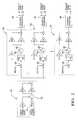
- FIG. 1is a diagrammatic drawing of the power management system of the present invention.
- FIG. 2is a process control diagram for the power management system of the present invention.
- FIG. 1is a diagrammatic drawing of the power management system of the present invention contained in a hybrid vehicle 10 .
- the hybrid vehicle 10includes a plurality of power stages 12 wired in parallel to produce a high output voltage V+, substantially in the range of 300 to 400 volts.
- the voltage V+is supplied to motor inverters 14 that chop or switch the provided DC voltage V+ to preferably generate three phase power for motor generators (MoGens) 18 .
- the MoGens 18preferably are AC induction machines, but may comprise any known electrical motor/generator technology, including, but not limited to, DC machines, synchronous machines, and switched reluctance machines.
- a filter capacitor 16is provided to stabilize the voltage on the high voltage DC bus.
- the MoGens 18are dynamically coupled to an internal combustion engine (ICE) 22 through a series or parallel coupling 24 and function as either a motor to propel the vehicle 10 or a generator to charge battery modules 26 within the power stages 12 , depending on the operating state of the vehicle 10 (i.e., braking, stopped or operating at a constant speed on a highway).
- ICEinternal combustion engine
- the bi-directional boost/buck converters 13provide a controllable interface between the low voltage battery modules 26 and a high voltage DC bus 48 .
- the MoGen 18operates as a motor, power flow is from left to right on FIG. 1, and the bi-directional boost/buck converters 13 are said to be operating in a boost mode.
- the MoGen 18operates in generator mode, power flow in FIG. 1 is from right to left, and the bi-directional boost/buck converters 13 are said to be operating in buck mode.
- the power stages 12 and motor inverters 14are controlled by a hybrid system controller 28 .
- the controller 28 , power stages 12 , and motor inverters 14may be configured as a unitary system.
- the hybrid system controller 28may comprise any type of control module or vehicle controller known in the art and is equipped with nonvolatile memory (NVM), random access memory (RAM), discrete and analog input/output (I/O), a central processing unit, communications interfaces for conventional and wireless (Bluetooth®) networking within an automotive communications network, etc.
- the hybrid system controller 28may communicate with the power modules 12 and motor inverters 14 using discrete signals, analog signals, or an automotive communications network.
- the controller 28 and inverter modules 14determine the direction of power or current flow for the MoGens 18 , according to the vehicle 10 operating state.
- the boost/buck DC—DC converters 13 within the power stages 12act to regulate the high voltage DC bus 48 to a voltage V+ via pulse-width modulation.
- a regeneration state(such as during braking) or charging condition, power flows from the MoGens 18 , via the inverter modules 14 , to charge the batteries 26 in the power stages 12 .
- a state where the MoGens 18 are needed to provide propulsionpower flows from the power stages 12 through the inverter modules 14 , to the MoGens 18 .
- the power stages 12each include a first output diode 29 , the batteries 26 , a current sensing element 32 , an inductor 34 , a boost switch 36 , and a buck switch 38 .
- the output diodes 29are coupled to the batteries 26 to provide power to accessory loads 40 in the vehicle 10 .
- the inductor 34is used to provide boost or buck energy storage and smooth the ripple current flowing into and out of the batteries 26 .
- the current sensing element 32provides current measurements to the controller 28 .
- the batteries 26 used in the present inventionare preferably low voltage batteries having a voltage in substantially the range of 12 volts to 42 volts.
- the batteriesare comprised of NiMH batteries.
- the batteries 26may comprise any known battery technology, including, but not limited to, lead acid and lithium polymer.
- the boost switch 36 and buck switch 38 depicted in FIG. 1are generic NPN transistors, but may be implemented using any known electrical switching device including, but not limited to, power MOSFETs, IBGTs, or bipolar transistors.
- a boost diode 37may comprise the integral body diode of buck switch 38 , when MOSFET devices are used to implement buck switch 38 .
- a buck diode 39may comprise the integral body diode of boost switch 36 , when MOSFET devices are used to implement boost switch 36 .
- FIG. 2A block diagram of the control system of the present invention implemented in controller 48 is shown in FIG. 2 .
- the control systemconsists of a single voltage controller 50 and a plurality of current controllers 54 .
- the voltage controller 50regulates the high voltage DC bus voltage to a desired setpoint value, as required by the motor inverters 14 .
- the current controllers 54regulate current flowing into or out of the individual batteries 26 , and one current controller 54 is used to control each power stage 12 in the system.
- currentwill be actively steered between the power stages 12 to provide improved aging characteristics of the batteries 26 by balancing charge and thermal operation.
- a motoring or traction mode for the vehicle 10 and the MoGens 18current from each battery 26 is controlled to obtain a balanced discharge. Since the power stages 12 are wired in parallel, the total load power is actively shared.
- a regeneration modecurrent is controlled into each energy storage block to obtain a balanced charge for the batteries 26 .
- the regenerative currentis divided between the stages 12 to charge the batteries 26 . Energy transfer between the batteries 26 in the power stages may also be used to balance the batteries 26 .
- a battery management control algorithm in the hybrid system controller 28will select what proportion of total load or regeneration current passes through each battery 26 such that the battery is actively maintained at the same average state of charge (SOC) as the other batteries 26 in the system.
- SOCis defined as the percentage of full capacity of a battery that is still available for further discharge.
- Accessory loads 40are tapped via the diodes 29 to the batteries 26 .
- the basic control loop of the present invention in FIG. 2is shown as a current-mode boost/buck control system.
- the voltage controller 50includes a sensed and amplified voltage provided by a voltage sensor 48 (seen in FIG. 1 ), a voltage setpoint Vreg, a summing junction 52 to generate a voltage error, and a proportional plus integral controller having proportional gain Kpv and integral gain Kiv acting on the error and generating an output at summing junction 53 .
- Each current controller 54regulates sensed current by current sensors 30 to a value demanded by the voltage loop 50 .
- each current controller 54can clamp the maximum positive or negative current through its corresponding power stage 12 at blocks 56 to within the range of the Ip variables, between Ip+ and Ip ⁇ , providing independent current limit control for each power stage 12 .
- This independent current limitingallows dynamic safe operating limits and may also be controlled to prevent excess current flow in the event of a shorted battery 26 or other fault in any of the power stages 12 .
- the Iadj(n) valuesare derived by an overall battery SOC management algorithm in the hybrid controller 28 . Since the Iadj(n) are continuously adjustable in all modes (traction, regenerative braking and at idle standstill), the balance of current flow between the power stages 12 is actively controlled to maintain the desired SOC in each battery. Any remaining battery SOC balancing required at the beginning or end of a drive cycle can be obtained by setting the Iadj(n) values to redistribute battery charge between the batteries 26 for equalization.
Landscapes
- Engineering & Computer Science (AREA)
- Power Engineering (AREA)
- Transportation (AREA)
- Mechanical Engineering (AREA)
- Life Sciences & Earth Sciences (AREA)
- Sustainable Development (AREA)
- Sustainable Energy (AREA)
- Electric Propulsion And Braking For Vehicles (AREA)
- Dc-Dc Converters (AREA)
- Inverter Devices (AREA)
Abstract
Description
Claims (20)
Priority Applications (3)
| Application Number | Priority Date | Filing Date | Title |
|---|---|---|---|
| US10/008,921US6608396B2 (en) | 2001-12-06 | 2001-12-06 | Electrical motor power management system |
| DE10254411ADE10254411A1 (en) | 2001-12-06 | 2002-11-21 | Power management system for an electric motor |
| JP2002346941AJP3655277B2 (en) | 2001-12-06 | 2002-11-29 | Electric motor power management system |
Applications Claiming Priority (1)
| Application Number | Priority Date | Filing Date | Title |
|---|---|---|---|
| US10/008,921US6608396B2 (en) | 2001-12-06 | 2001-12-06 | Electrical motor power management system |
Publications (2)
| Publication Number | Publication Date |
|---|---|
| US20030107352A1 US20030107352A1 (en) | 2003-06-12 |
| US6608396B2true US6608396B2 (en) | 2003-08-19 |
Family
ID=21734486
Family Applications (1)
| Application Number | Title | Priority Date | Filing Date |
|---|---|---|---|
| US10/008,921Expired - Fee RelatedUS6608396B2 (en) | 2001-12-06 | 2001-12-06 | Electrical motor power management system |
Country Status (3)
| Country | Link |
|---|---|
| US (1) | US6608396B2 (en) |
| JP (1) | JP3655277B2 (en) |
| DE (1) | DE10254411A1 (en) |
Cited By (99)
| Publication number | Priority date | Publication date | Assignee | Title |
|---|---|---|---|---|
| US20020145404A1 (en)* | 2001-04-05 | 2002-10-10 | Electrofuel, Inc. | Energy storage device and loads having variable power rates |
| US20030020330A1 (en)* | 2001-07-12 | 2003-01-30 | Cratty William E. | DC ladder bus |
| US20030132669A1 (en)* | 2002-01-16 | 2003-07-17 | Adtran, Inc. | Method and apparatus for forced current sharing in diode-connected redundant power supplies |
| US20030214271A1 (en)* | 2002-05-17 | 2003-11-20 | Bradley Larry D. | System and method for bi-directional power conversion in a portable device |
| US20040130214A1 (en)* | 2003-01-06 | 2004-07-08 | Murty Balarama Vempaty | Dual voltage architecture for automotive electrical systems |
| US20040145338A1 (en)* | 2001-12-26 | 2004-07-29 | Makoto Nakamura | Electric load apparatus electric load controlling method and computer readable recording medium recording program for causing computer to execute control of electric load |
| US20040155468A1 (en)* | 2003-02-12 | 2004-08-12 | Tai-Her Yang | Series and parallel combined dual power drive system |
| US20040251691A1 (en)* | 2003-06-13 | 2004-12-16 | Ge Medical Systems Global Technology Company Llc | Method and system for optimizing energy storage in hybrid off-highway vehicle systems and trolley connected ohv systems |
| US20050116669A1 (en)* | 2002-02-07 | 2005-06-02 | Elin Ebg Traction Gmbh | Vehicle comprising a battery drive and a method for operating a vehicle of this type |
| US20050162023A1 (en)* | 2002-09-17 | 2005-07-28 | Masakazu Habu | Electric load device, abnormally handling method, and computer-readable recordinging medium storing therein program for causing computer to execute electric load abnormality handling |
| US20050161948A1 (en)* | 2003-02-12 | 2005-07-28 | Tai-Her Yang | Partial-powered series hybrid driving system |
| US20050161268A1 (en)* | 2003-02-12 | 2005-07-28 | Tai-Her Yang | Series-parallel dual power hybrid driving system |
| US20050206331A1 (en)* | 2004-03-08 | 2005-09-22 | Railpower Technologies Corp. | Hybrid locomotive configuration |
| US20060052915A1 (en)* | 2003-03-11 | 2006-03-09 | Toyota Jidosha Kabushiki Kaisha | Motor drive apparatus, hybrid vehicle drive apparatus using the same, and computer readable recording medium recorded with program for causing computer to perform control of motor drive apparatus |
| US20060102396A1 (en)* | 2002-07-11 | 2006-05-18 | Peugeot Citroen Automobiles S.A. | Power transmission method and device for a motor vehicle comprising a heat engine and at least one electric machine |
| US20060170389A1 (en)* | 2005-01-31 | 2006-08-03 | Caterpillar Inc | Medium voltage switched reluctance motors used in traction applications |
| WO2006020667A3 (en)* | 2004-08-09 | 2006-08-10 | Railpower Technologies Corp | Locomotive power train architecture |
| US20060226703A1 (en)* | 2005-04-08 | 2006-10-12 | Dejan Schreiber | Circuitry and related control method for an electric or hybrid vehicle with two direct current sources |
| US20060266255A1 (en)* | 2005-04-25 | 2006-11-30 | Railpower Technologies Corp. | Locomotive engine start method |
| US20070000704A1 (en)* | 2005-04-29 | 2007-01-04 | Icemaster Gmbh Generatoren Und Kaltetechnik | Power supply device, particularly for a motor vehicle |
| US20070007939A1 (en)* | 2005-05-16 | 2007-01-11 | Miller John M | Low voltage electrical vehicle propulsion system using double layer capacitors |
| US20070193794A1 (en)* | 2003-10-03 | 2007-08-23 | Letourneau Technologies, Inc. | Vehicle for materials handling and other industrial uses |
| WO2007123222A1 (en) | 2006-04-24 | 2007-11-01 | Toyota Jidosha Kabushiki Kaisha | Power supply system and vehicle |
| WO2007125673A1 (en) | 2006-03-31 | 2007-11-08 | Toyota Jidosha Kabushiki Kaisha | Power supply system and vehicle including the same |
| WO2007148592A1 (en) | 2006-06-23 | 2007-12-27 | Toyota Jidosha Kabushiki Kaisha | Power supply system and vehicle having the same |
| WO2008004647A1 (en) | 2006-07-06 | 2008-01-10 | Toyota Jidosha Kabushiki Kaisha | Power supply system and vehicle having the same |
| US20080036431A1 (en)* | 2004-08-27 | 2008-02-14 | Robert Bosch Gmbh | Voltage Regulator Having Overvoltage Protection |
| US7349797B2 (en) | 2004-03-30 | 2008-03-25 | Railpower Technologies Corp | Emission management for a hybrid locomotive |
| US20080111508A1 (en)* | 2001-04-05 | 2008-05-15 | Electrovaya Inc. | Energy storage device for loads having variabl power rates |
| US20080113226A1 (en)* | 2001-04-05 | 2008-05-15 | Electrovaya Inc. | Energy storage device for loads having variable power rates |
| WO2008072762A1 (en) | 2006-12-14 | 2008-06-19 | Toyota Jidosha Kabushiki Kaisha | Power supply system, vehicle using the same, and its control method |
| WO2008081691A1 (en) | 2007-01-04 | 2008-07-10 | Toyota Jidosha Kabushiki Kaisha | Power supply system, vehicle using the same, and its control method |
| US20080183361A1 (en)* | 2007-01-31 | 2008-07-31 | Katsuya Oyama | Controller for inverter |
| WO2008099953A1 (en) | 2007-02-13 | 2008-08-21 | Toyota Jidosha Kabushiki Kaisha | Drive force generation system, vehicle using the system, and method for controlling the system |
| US20080218104A1 (en)* | 2007-03-09 | 2008-09-11 | Srdjan Lukic | Power management for multi-module energy storage systems in electric, hybrid electric, and fuel cell vehicles |
| US20080258656A1 (en)* | 2007-04-17 | 2008-10-23 | Denso Corporation | Control apparatus for electric vehicles |
| US20080264291A1 (en)* | 2005-10-19 | 2008-10-30 | Rail Power Technologies Corp | Design of a Large Low Maintenance Battery Pack for a Hybrid Locomotive |
| US20080284384A1 (en)* | 2007-05-17 | 2008-11-20 | Denso Corporation | Vehicle-use power supply control apparatus |
| US7467830B2 (en) | 2004-02-17 | 2008-12-23 | Railpower Technologies Corp. | Managing wheel slip in a locomotive |
| US20090066277A1 (en)* | 2006-06-22 | 2009-03-12 | Toyota Jidosha Kabushiki Kaisha | Voltage Conversion Apparatus and Vehicle Including the Same |
| US7507500B2 (en) | 2004-05-17 | 2009-03-24 | Railpower Technologies Corp. | Design of a large battery pack for a hybrid locomotive |
| US20090160248A1 (en)* | 2006-08-02 | 2009-06-25 | Toyota Jidosha Kabushiki Kaisha | Power Supply Device and Vehicle Equipped With the Same |
| US20090179616A1 (en)* | 2006-07-10 | 2009-07-16 | Toyota Jidosha Kabushiki Kaisha | Power Supply System, Vehicle with the Same and Temperature Managing Method |
| US20090183934A1 (en)* | 2006-07-07 | 2009-07-23 | Toyota Jidosha Kabushiki Kaisha | Power supply system, vehicle provided with the same, power supply system control method and computer-readable recording medium bearing program for causing computer to control the power supply system |
| US7565867B2 (en) | 2004-09-03 | 2009-07-28 | Frank Wegner Donnelly | Multiple engine locomotive configuration |
| US20090195067A1 (en)* | 2006-09-04 | 2009-08-06 | Toyota Jidosha Kabushiki Kaisha | Power supply system, vehicle with the same, temperature increase control method for power storage device and computer-readable recording medium bearing program for causing computer to execute temperature increase control of power storage device |
| US20090243385A1 (en)* | 2006-07-10 | 2009-10-01 | Toyota Jidosha Kabushiki Kaisha | Power Supply System, Vehicle Using the Same and its Control Method |
| US20090261658A1 (en)* | 2008-04-18 | 2009-10-22 | Toyota Jidosha Kabushiki Kaisha | Power supply system, vehicle having power supply system, and control method of power supply system |
| US20090273235A1 (en)* | 2006-04-24 | 2009-11-05 | Toyota Jidosha Kabushiki Kaisha | Power Supply System and Vehicle |
| US20090315403A1 (en)* | 2006-07-31 | 2009-12-24 | Shinji Ichikawa | Power supply system, vehicle provided with the same, temperature rise control method of power storage device, and computer-readable recording medium with program recorded thereon for causing computer to execute temperature rise control of power storage device |
| US20100001587A1 (en)* | 2008-07-01 | 2010-01-07 | Satcon Technology Corporation | Photovoltaic dc/dc micro-converter |
| US20100006385A1 (en)* | 2007-02-20 | 2010-01-14 | Alstom Transport Sa | Electrical equipment arranged in the roof of an electrically driven railway vehicle |
| US20100013301A1 (en)* | 2006-11-13 | 2010-01-21 | Toyota Jidosha Kabushiki Kaisha | Electric power supply system |
| US20100033011A1 (en)* | 2007-03-29 | 2010-02-11 | Mitsubishi Heavy Industries Ltd | Electric vehicle drive dc-dc converter and electric vehicle |
| US20100085787A1 (en)* | 2008-10-03 | 2010-04-08 | Ajit Wasant Kane | System and method for powering a hybrid electric vehicle |
| US20100094497A1 (en)* | 2008-10-15 | 2010-04-15 | Toyota Jidosha Kabushiki Kaisha | Electrical powered vehicle incorporating motor and inverter, and control method therefor |
| USRE41303E1 (en) | 2001-10-25 | 2010-05-04 | Toyota Jidosha Kabushiki Kaisha | Load driver and control method for safely driving DC load and computer-readable recording medium with program recorded thereon for allowing computer to execute the control |
| US20100123438A1 (en)* | 2007-07-18 | 2010-05-20 | Toyota Jidosha Kabushiki Kaisha | Electric vehicle and electric vehicle secondary battery charge method |
| US20100131137A1 (en)* | 2007-06-15 | 2010-05-27 | Toyota Jidosha Kabushiki Kaisha | Power supply system, vehicle with the same and charge/discharge control method |
| US20100133913A1 (en)* | 2007-07-25 | 2010-06-03 | Toyota Jidosha Kabushiki Kaisha | Control device and control method for electric system |
| US20100141213A1 (en)* | 2007-06-06 | 2010-06-10 | Kabushiki Kaisha Toyota Jidoshokki | Power supply apparatus for vehicle |
| US20100181829A1 (en)* | 2007-07-24 | 2010-07-22 | Toyota Jidosha Kabushiki Kaisha | Power supply system and electric powered vehicle including power supply system, and method for controlling power supply system |
| US20110011659A1 (en)* | 2009-07-20 | 2011-01-20 | International Truck Intellectual Property Company, Llc | Scalable, hybrid energy storage for plug-in vehicles |
| US20110082611A1 (en)* | 2008-06-27 | 2011-04-07 | Toyota Jidosha Kabushiki Kaisha | Control apparatus and control method for hybrid vehicle |
| US7940016B2 (en) | 2004-08-09 | 2011-05-10 | Railpower, Llc | Regenerative braking methods for a hybrid locomotive |
| US20110133547A1 (en)* | 2009-12-03 | 2011-06-09 | Hyundai Motor Company | Motor drive system for hybrid vehicle and method for controlling the same in the event of failure |
| US20110178664A1 (en)* | 2008-10-31 | 2011-07-21 | Toyota Jidosha Kabushiki Kaisha | Hybrid vehicle and method for controlling the same |
| US20110187183A1 (en)* | 2010-02-04 | 2011-08-04 | Toyota Jidosha Kabushiki Kaisha | Power supply apparatus for vehicle |
| US20110208383A1 (en)* | 2008-10-31 | 2011-08-25 | Masaya Yamamoto | Electric powered vehicle and control method for the same |
| US20110234162A1 (en)* | 2008-12-19 | 2011-09-29 | Nissan Motor Co., Ltd. | Secondary battery system |
| US20110260690A1 (en)* | 2010-04-27 | 2011-10-27 | Honeywell International Inc. | Electric accumulators having self regulated battery with integrated bi-directional power management and protection |
| US20110285208A1 (en)* | 2010-05-24 | 2011-11-24 | Xiao yan yi | Power supply method with parallel-connected batteries |
| CN102398507A (en)* | 2010-09-02 | 2012-04-04 | 通用汽车环球科技运作有限责任公司 | Method and apparatus for controlling high-voltage battery connection for hybrid powertrain system |
| US20120091967A1 (en)* | 2010-10-14 | 2012-04-19 | Shinya Kawamoto | Power stabilization system and power stabilizing method |
| CN101529690B (en)* | 2006-10-24 | 2012-07-04 | 丰田自动车株式会社 | Power supply system, vehicle with power supply system, control method of power supply system |
| US8229616B2 (en) | 2009-03-05 | 2012-07-24 | Toyota Jidosha Kabushiki Kaisha | Charging/discharging control system for hybrid vehicle and method for controlling same |
| CN102717723A (en)* | 2012-05-15 | 2012-10-10 | 北京汽车新能源汽车有限公司 | Optimized energy system for electric automobile |
| US8292770B2 (en) | 2010-11-09 | 2012-10-23 | Aram Novikov | Multi-core electric machines |
| WO2013015817A1 (en)* | 2011-07-28 | 2013-01-31 | International Truck Intellectual Property Company, Llc | Motor vehicle with multiple bus power system |
| US20130049648A1 (en)* | 2011-08-25 | 2013-02-28 | Hamilton Sundstrand Corporation | Direct current bus management controller |
| US8538616B2 (en) | 2008-10-31 | 2013-09-17 | Toyota Jidosha Kabushiki Kaisha | Power supply system for electrically powered vehicle, electrically powered vehicle, and method for controlling the same |
| US8565953B2 (en)* | 2009-06-10 | 2013-10-22 | Toyota Jidosha Kabushiki Kaisha | Hybrid vehicle and method for controlling the same |
| US20130332017A1 (en)* | 2012-06-12 | 2013-12-12 | Toyota Jidosha Kabushiki Kaisha | Hybrid motor vehicle |
| US8742722B2 (en) | 2010-08-27 | 2014-06-03 | International Rectifier Corporation | Dynamic power management system and method |
| US20140265945A1 (en)* | 2013-03-15 | 2014-09-18 | Infineon Technologies Austria Ag | Electric Drive System |
| US20140318410A1 (en)* | 2013-04-26 | 2014-10-30 | Progress Rail Services Corporation | Locomotive with variable power modules |
| US8952570B2 (en) | 2011-08-25 | 2015-02-10 | Hamilton Sundstrand Corporation | Active damping with a switched capacitor |
| US20150115709A1 (en)* | 2008-10-22 | 2015-04-30 | General Electric Company | Apparatus for energy transfer using converter and method of manufacturing same |
| US9048353B2 (en) | 2008-07-01 | 2015-06-02 | Perfect Galaxy International Limited | Photovoltaic DC/DC micro-converter |
| US9248825B2 (en) | 2007-05-16 | 2016-02-02 | General Electric Company | Method of operating vehicle and associated system |
| US9257863B2 (en) | 2012-03-26 | 2016-02-09 | Panasonic Intellectual Property Management Co., Ltd. | Charge and discharge control device and charge and discharge control method |
| US9789780B2 (en) | 2009-12-18 | 2017-10-17 | General Electric Company | Apparatus and method for rapid charging using shared power electronics |
| US9800182B2 (en) | 2012-12-03 | 2017-10-24 | General Electric Company | Electric drive system and energy management method |
| US9821668B2 (en) | 2012-05-21 | 2017-11-21 | General Electric Company | Method and apparatus for charging multiple energy storage devices |
| US20170359013A1 (en)* | 2016-06-14 | 2017-12-14 | Arm Ltd. | Method and apparatus for operating an electric motor |
| US10135377B2 (en)* | 2016-06-14 | 2018-11-20 | Arm Ltd. | Method and apparatus for operating an electric motor |
| US10771001B2 (en) | 2015-09-11 | 2020-09-08 | Invertedpower Pty Ltd | Controller for an inductive load having one or more inductive windings |
| US11267358B2 (en) | 2017-05-08 | 2022-03-08 | Invertedpower Pty Ltd | Vehicle charging station |
| US11479139B2 (en) | 2015-09-11 | 2022-10-25 | Invertedpower Pty Ltd | Methods and systems for an integrated charging system for an electric vehicle |
Families Citing this family (152)
| Publication number | Priority date | Publication date | Assignee | Title |
|---|---|---|---|---|
| JP2004248432A (en)* | 2003-02-14 | 2004-09-02 | Toyota Motor Corp | Driving device and automobile equipped with the same |
| US6882129B2 (en)* | 2003-03-26 | 2005-04-19 | General Motors Corporation | Battery pack for a battery-powered vehicle |
| US6989653B2 (en)* | 2003-05-09 | 2006-01-24 | Mitsubishi Denki Kabushiki Kaisha | Battery power circuit and automobile battery power circuit |
| US7006898B2 (en)* | 2003-07-17 | 2006-02-28 | Proton Energy Systems, Inc. | Method and apparatus for operating and controlling a power system |
| US20060261783A1 (en)* | 2005-05-23 | 2006-11-23 | Paul Gamboa | Electronic battery module (EBM) with bidirectional DC-DC converter |
| US11881814B2 (en) | 2005-12-05 | 2024-01-23 | Solaredge Technologies Ltd. | Testing of a photovoltaic panel |
| US10693415B2 (en) | 2007-12-05 | 2020-06-23 | Solaredge Technologies Ltd. | Testing of a photovoltaic panel |
| JP4552904B2 (en)* | 2006-06-23 | 2010-09-29 | トヨタ自動車株式会社 | Vehicle power supply device and vehicle equipped with the same |
| JP4379441B2 (en)* | 2006-07-18 | 2009-12-09 | トヨタ自動車株式会社 | Power supply system, vehicle equipped with the same, power storage device temperature rise control method, and computer-readable recording medium storing a program for causing a computer to execute power storage device temperature rise control |
| JP4905300B2 (en)* | 2006-09-28 | 2012-03-28 | トヨタ自動車株式会社 | Power supply system, vehicle equipped with the same, control method for power supply system, and computer-readable recording medium recording a program for causing a computer to execute the control method |
| JP4321576B2 (en) | 2006-10-24 | 2009-08-26 | トヨタ自動車株式会社 | Power supply device and vehicle including the same |
| JP4665890B2 (en)* | 2006-11-22 | 2011-04-06 | トヨタ自動車株式会社 | Power supply device and vehicle equipped with power supply device |
| US11735910B2 (en) | 2006-12-06 | 2023-08-22 | Solaredge Technologies Ltd. | Distributed power system using direct current power sources |
| US8319471B2 (en) | 2006-12-06 | 2012-11-27 | Solaredge, Ltd. | Battery power delivery module |
| US11309832B2 (en) | 2006-12-06 | 2022-04-19 | Solaredge Technologies Ltd. | Distributed power harvesting systems using DC power sources |
| US11855231B2 (en) | 2006-12-06 | 2023-12-26 | Solaredge Technologies Ltd. | Distributed power harvesting systems using DC power sources |
| US8963369B2 (en) | 2007-12-04 | 2015-02-24 | Solaredge Technologies Ltd. | Distributed power harvesting systems using DC power sources |
| US8816535B2 (en) | 2007-10-10 | 2014-08-26 | Solaredge Technologies, Ltd. | System and method for protection during inverter shutdown in distributed power installations |
| US8319483B2 (en) | 2007-08-06 | 2012-11-27 | Solaredge Technologies Ltd. | Digital average input current control in power converter |
| US8618692B2 (en) | 2007-12-04 | 2013-12-31 | Solaredge Technologies Ltd. | Distributed power system using direct current power sources |
| US8473250B2 (en) | 2006-12-06 | 2013-06-25 | Solaredge, Ltd. | Monitoring of distributed power harvesting systems using DC power sources |
| US8384243B2 (en) | 2007-12-04 | 2013-02-26 | Solaredge Technologies Ltd. | Distributed power harvesting systems using DC power sources |
| US11888387B2 (en) | 2006-12-06 | 2024-01-30 | Solaredge Technologies Ltd. | Safety mechanisms, wake up and shutdown methods in distributed power installations |
| US9088178B2 (en) | 2006-12-06 | 2015-07-21 | Solaredge Technologies Ltd | Distributed power harvesting systems using DC power sources |
| US8013472B2 (en) | 2006-12-06 | 2011-09-06 | Solaredge, Ltd. | Method for distributed power harvesting using DC power sources |
| US11687112B2 (en) | 2006-12-06 | 2023-06-27 | Solaredge Technologies Ltd. | Distributed power harvesting systems using DC power sources |
| US8947194B2 (en) | 2009-05-26 | 2015-02-03 | Solaredge Technologies Ltd. | Theft detection and prevention in a power generation system |
| US9130401B2 (en) | 2006-12-06 | 2015-09-08 | Solaredge Technologies Ltd. | Distributed power harvesting systems using DC power sources |
| US12316274B2 (en) | 2006-12-06 | 2025-05-27 | Solaredge Technologies Ltd. | Pairing of components in a direct current distributed power generation system |
| US9112379B2 (en) | 2006-12-06 | 2015-08-18 | Solaredge Technologies Ltd. | Pairing of components in a direct current distributed power generation system |
| US11296650B2 (en) | 2006-12-06 | 2022-04-05 | Solaredge Technologies Ltd. | System and method for protection during inverter shutdown in distributed power installations |
| US11569659B2 (en) | 2006-12-06 | 2023-01-31 | Solaredge Technologies Ltd. | Distributed power harvesting systems using DC power sources |
| JP4513812B2 (en) | 2007-01-04 | 2010-07-28 | トヨタ自動車株式会社 | Vehicle power supply device and vehicle |
| JP4840197B2 (en)* | 2007-03-06 | 2011-12-21 | トヨタ自動車株式会社 | VEHICLE POWER DEVICE AND VEHICLE POWER DEVICE CONTROL METHOD |
| JP4915273B2 (en) | 2007-04-25 | 2012-04-11 | トヨタ自動車株式会社 | Electrical device and method for controlling electrical device |
| JP4882850B2 (en)* | 2007-04-25 | 2012-02-22 | トヨタ自動車株式会社 | Power supply system, power supply system control method, and computer-readable recording medium storing a program for causing a computer to execute the power supply system control method |
| EP1990887A1 (en)* | 2007-05-07 | 2008-11-12 | STMicroelectronics S.r.l. | A power management unit for battery-operated devices |
| JP4816575B2 (en)* | 2007-06-06 | 2011-11-16 | トヨタ自動車株式会社 | Power supply system, vehicle equipped with the same, control method of power supply system, and computer-readable recording medium recording a program for causing a computer to execute the control method |
| WO2008153174A1 (en)* | 2007-06-11 | 2008-12-18 | Toyota Jidosha Kabushiki Kaisha | Electric system control device and control method |
| JP4894656B2 (en)* | 2007-07-13 | 2012-03-14 | トヨタ自動車株式会社 | vehicle |
| FR2919146A1 (en)* | 2007-07-19 | 2009-01-23 | Gen Electric | X-RAY APPARATUS |
| US7952225B2 (en)* | 2007-07-20 | 2011-05-31 | Diversified Technology, Inc. | Modular vehicle power system |
| JP2009044862A (en)* | 2007-08-09 | 2009-02-26 | Toyota Motor Corp | Electric vehicle power supply control device and power supply system |
| JP4640391B2 (en)* | 2007-08-10 | 2011-03-02 | トヨタ自動車株式会社 | Power supply system and vehicle equipped with the same |
| US7825615B2 (en) | 2007-10-16 | 2010-11-02 | Glj, Llc | Intelligent motorized appliances with multiple power sources |
| JP4380772B2 (en)* | 2007-10-16 | 2009-12-09 | トヨタ自動車株式会社 | POWER SUPPLY DEVICE, VEHICLE EQUIPPED WITH THE SAME, CONTROL METHOD FOR POWER SUPPLY DEVICE, AND COMPUTER-READABLE RECORDING MEDIUM CONTAINING PROGRAM FOR CAUSING COMPUTER TO EXECUTE THE CONTROL METHOD |
| JP4305553B2 (en)* | 2007-10-23 | 2009-07-29 | トヨタ自動車株式会社 | Electric vehicle |
| US11264947B2 (en) | 2007-12-05 | 2022-03-01 | Solaredge Technologies Ltd. | Testing of a photovoltaic panel |
| WO2009072076A2 (en) | 2007-12-05 | 2009-06-11 | Solaredge Technologies Ltd. | Current sensing on a mosfet |
| CN105244905B (en) | 2007-12-05 | 2019-05-21 | 太阳能安吉有限公司 | Release mechanism in distributed power device is waken up and method for closing |
| WO2009073867A1 (en) | 2007-12-05 | 2009-06-11 | Solaredge, Ltd. | Parallel connected inverters |
| WO2009103079A2 (en)* | 2008-02-15 | 2009-08-20 | Atieva, Inc. | Method of electrically connecting cell terminals in a battery pack |
| US8111052B2 (en) | 2008-03-24 | 2012-02-07 | Solaredge Technologies Ltd. | Zero voltage switching |
| DE102008000904A1 (en)* | 2008-04-01 | 2009-10-08 | Robert Bosch Gmbh | Method and device for controlling an electric machine of a hybrid drive with increased availability |
| EP2294669B8 (en) | 2008-05-05 | 2016-12-07 | Solaredge Technologies Ltd. | Direct current power combiner |
| US20090327165A1 (en)* | 2008-06-30 | 2009-12-31 | Kaufman Jonathan J | System and method for re-supplying energy to a battery-powered electric vehicle |
| DE102008040719A1 (en)* | 2008-07-25 | 2010-01-28 | Robert Bosch Gmbh | Multi-phase clocked DC / DC converter |
| JP4992868B2 (en)* | 2008-08-29 | 2012-08-08 | トヨタ自動車株式会社 | Power control system |
| JP5071322B2 (en)* | 2008-09-18 | 2012-11-14 | トヨタ自動車株式会社 | Power control system |
| US8718847B2 (en) | 2008-10-14 | 2014-05-06 | Toyota Jidosha Kabushiki Kaisha | Control apparatus and control method for hybrid vehicle |
| JP4811446B2 (en)* | 2008-10-21 | 2011-11-09 | トヨタ自動車株式会社 | Power supply system, vehicle equipped with the same, and control method of power supply system |
| US7932633B2 (en) | 2008-10-22 | 2011-04-26 | General Electric Company | Apparatus for transferring energy using power electronics and machine inductance and method of manufacturing same |
| EP2343211B1 (en) | 2008-10-31 | 2018-04-04 | Toyota Jidosha Kabushiki Kaisha | Electric power source system for electrically driven vehicle and its control method |
| CN102196940B (en) | 2008-10-31 | 2013-09-25 | 丰田自动车株式会社 | Power supply system for electric vehicle and control method for the same |
| EP2353919A4 (en) | 2008-10-31 | 2016-08-10 | Toyota Motor Co Ltd | ELECTRIC SOURCE SYSTEM FOR AN ELECTRIC VEHICLE AND METHOD OF CONTROLLING THE SAME |
| JP5493367B2 (en)* | 2009-01-29 | 2014-05-14 | 株式会社エクォス・リサーチ | Battery hybrid system |
| KR20110139244A (en)* | 2009-03-02 | 2011-12-28 | 엘리먼트 에너지 | Systems and Methods for Scalable Configuration of Intelligent Energy Storage Packs |
| US9397502B2 (en) | 2009-03-02 | 2016-07-19 | Volterra Semiconductor LLC | System and method for proportioned power distribution in power converter arrays |
| US10283974B2 (en) | 2009-03-02 | 2019-05-07 | Volterra Semiconductor LLC | Systems and methods for intelligent, adaptive management of energy storage packs |
| WO2010128550A1 (en) | 2009-05-08 | 2010-11-11 | トヨタ自動車株式会社 | Power supply system and vehicle equipped with power supply system |
| JP5218275B2 (en)* | 2009-05-18 | 2013-06-26 | トヨタ自動車株式会社 | Hybrid vehicle and control method thereof |
| WO2010137128A1 (en)* | 2009-05-27 | 2010-12-02 | トヨタ自動車株式会社 | Converter control device and electric vehicle using the same |
| JP5206873B2 (en)* | 2009-06-05 | 2013-06-12 | トヨタ自動車株式会社 | Electric vehicle and method for setting total allowable discharge energy in electric vehicle |
| JP5299097B2 (en)* | 2009-06-05 | 2013-09-25 | トヨタ自動車株式会社 | Power supply device, control method therefor, power output device, and hybrid vehicle |
| WO2010143279A1 (en)* | 2009-06-10 | 2010-12-16 | トヨタ自動車株式会社 | Power supply system for electric vehicle, electric vehicle, and control method of power supply system for electric vehicle |
| US8509978B2 (en) | 2009-06-10 | 2013-08-13 | Toyota Jidosha Kabushiki Kaisha | Electric powered vehicle and control method for the same |
| WO2011014595A2 (en) | 2009-07-31 | 2011-02-03 | Thermo King Corporation | Bi-directional battery voltage converter |
| EP2299556B1 (en)* | 2009-09-18 | 2019-07-03 | CTEK Sweden AB | Battery charging and electrical energy delivery system and battery operated system |
| US12418177B2 (en) | 2009-10-24 | 2025-09-16 | Solaredge Technologies Ltd. | Distributed power system using direct current power sources |
| RU2408132C1 (en)* | 2009-11-30 | 2010-12-27 | Открытое акционерное общество "Ракетно-космическая корпорация "Энергия" имени С.П. Королева" | Device of dc drive control |
| DE102009054820A1 (en)* | 2009-12-17 | 2011-06-22 | Robert Bosch GmbH, 70469 | Energy storage system and method for its operation |
| KR101143367B1 (en) | 2010-01-06 | 2012-05-18 | 이경산전 주식회사 | Method for design of excitation chopper for propulsion system of ktx high speed train |
| DE102010001817A1 (en)* | 2010-02-11 | 2011-08-11 | Robert Bosch GmbH, 70469 | Control concept with limit value management for DC / DC converters in an energy system |
| US8450021B2 (en) | 2010-03-15 | 2013-05-28 | GM Global Technology Operations LLC | Method for HV bus voltage control in fuel cell vehicles featuring HV lithium batteries |
| US8872518B2 (en) | 2010-06-25 | 2014-10-28 | Atieva, Inc. | Determining the state of-charge of batteries via selective sampling of extrapolated open circuit voltage |
| JP5647823B2 (en)* | 2010-06-25 | 2015-01-07 | 株式会社三社電機製作所 | Charge / discharge device for storage battery |
| DE102010035073A1 (en)* | 2010-08-21 | 2014-06-18 | Jens Goldenstein | Energy Management System |
| DE102010044497A1 (en)* | 2010-09-06 | 2012-03-08 | Magna E-Car Systems Gmbh & Co Og | Apparatus for connecting power supply modules to electrical device, has primary and secondary direct current (DC)/DC transducers that are connected to respective power supply modules through respective electrical device contacts |
| FR2965123B1 (en)* | 2010-09-20 | 2021-07-30 | Valeo Systemes De Controle Moteur | DEVICE AND METHOD FOR MANAGING THE ELECTRIC CURRENT SUPPLY OF A LOAD |
| US9290097B2 (en) | 2010-11-05 | 2016-03-22 | Robert Louis Steigerwald | Apparatus for transferring energy using onboard power electronics with high-frequency transformer isolation and method of manufacturing same |
| GB2485527B (en) | 2010-11-09 | 2012-12-19 | Solaredge Technologies Ltd | Arc detection and prevention in a power generation system |
| US10673222B2 (en) | 2010-11-09 | 2020-06-02 | Solaredge Technologies Ltd. | Arc detection and prevention in a power generation system |
| US10673229B2 (en) | 2010-11-09 | 2020-06-02 | Solaredge Technologies Ltd. | Arc detection and prevention in a power generation system |
| US10230310B2 (en) | 2016-04-05 | 2019-03-12 | Solaredge Technologies Ltd | Safety switch for photovoltaic systems |
| GB2486408A (en) | 2010-12-09 | 2012-06-20 | Solaredge Technologies Ltd | Disconnection of a string carrying direct current |
| GB2483317B (en) | 2011-01-12 | 2012-08-22 | Solaredge Technologies Ltd | Serially connected inverters |
| DE102011002608A1 (en)* | 2011-01-13 | 2012-07-19 | Sb Limotive Company Ltd. | Method for charging a DC link capacitor |
| US8922063B2 (en)* | 2011-04-27 | 2014-12-30 | Green Charge Networks, Llc | Circuit for rendering energy storage devices parallelable |
| JP5278715B2 (en)* | 2011-05-30 | 2013-09-04 | トヨタ自動車株式会社 | Fuel cell system |
| CN102931862A (en)* | 2011-08-12 | 2013-02-13 | 旭丽电子(广州)有限公司 | Direct-current/alternating-current conversion system and direct-current/alternating-current conversion circuit |
| US8570005B2 (en) | 2011-09-12 | 2013-10-29 | Solaredge Technologies Ltd. | Direct current link circuit |
| CN102361336A (en)* | 2011-10-26 | 2012-02-22 | 耿直 | Working method of single boost storage battery pack and single storage battery boost group controller |
| GB2498365A (en) | 2012-01-11 | 2013-07-17 | Solaredge Technologies Ltd | Photovoltaic module |
| US9853565B2 (en) | 2012-01-30 | 2017-12-26 | Solaredge Technologies Ltd. | Maximized power in a photovoltaic distributed power system |
| GB2498790A (en) | 2012-01-30 | 2013-07-31 | Solaredge Technologies Ltd | Maximising power in a photovoltaic distributed power system |
| GB2498791A (en) | 2012-01-30 | 2013-07-31 | Solaredge Technologies Ltd | Photovoltaic panel circuitry |
| DE102012201605A1 (en)* | 2012-02-03 | 2013-08-08 | Robert Bosch Gmbh | Method for adjusting total current of battery in vehicle, involves connecting battery strands to input of converter, and individually adjusting current flowing through strands by converter for adjusting total current of battery |
| GB2499991A (en) | 2012-03-05 | 2013-09-11 | Solaredge Technologies Ltd | DC link circuit for photovoltaic array |
| US10115841B2 (en) | 2012-06-04 | 2018-10-30 | Solaredge Technologies Ltd. | Integrated photovoltaic panel circuitry |
| DE102012209741A1 (en)* | 2012-06-11 | 2013-12-12 | Varta Microbattery Gmbh | Method for operating battery, involves terminating battery supplied with operating energy from energy storage, and supplying battery with operating energy obtained from direct current (DC) output voltage supplied to DC bus |
| JP5712999B2 (en)* | 2012-12-26 | 2015-05-07 | トヨタ自動車株式会社 | Hybrid car |
| ITFI20130027A1 (en)* | 2013-02-04 | 2014-08-05 | Paolo Canova | DEVICE FOR TESTING AND CONDITIONING BATTERIES, PROVIDED WITH MEANS OF RECOVERY OF BATTERY DISCHARGE ENERGY. |
| US9548619B2 (en) | 2013-03-14 | 2017-01-17 | Solaredge Technologies Ltd. | Method and apparatus for storing and depleting energy |
| EP3506370B1 (en) | 2013-03-15 | 2023-12-20 | Solaredge Technologies Ltd. | Bypass mechanism |
| JP6227984B2 (en)* | 2013-11-27 | 2017-11-08 | 京セラ株式会社 | Power conversion device and power conversion method |
| CN103640489A (en)* | 2013-12-18 | 2014-03-19 | 电子科技大学 | Drive device of electric automobile |
| EP2965935B1 (en) | 2014-06-17 | 2017-10-04 | FERRARI S.p.A. | Electric power system of a vehicle with electric propulsion |
| KR101558797B1 (en) | 2014-08-12 | 2015-10-07 | 현대자동차주식회사 | System and method for controlling Battery to extend driving mileage |
| CN104201882B (en)* | 2014-08-20 | 2017-04-12 | 华为技术有限公司 | Non-isolated voltage-stabilization current-sharing circuit and power supply system |
| JP6393559B2 (en)* | 2014-08-29 | 2018-09-19 | 三洋電機株式会社 | Power storage system, management device, and DC / DC converter |
| FR3033755B1 (en)* | 2015-03-17 | 2017-03-03 | Renault Sas | METHOD AND DEVICE FOR MANAGING THE ENERGY OF A HYBRID MOTOR VEHICLE |
| JP6348460B2 (en)* | 2015-07-08 | 2018-06-27 | 東芝三菱電機産業システム株式会社 | Power conversion system |
| JP6278007B2 (en) | 2015-07-14 | 2018-02-14 | トヨタ自動車株式会社 | Power system |
| CN107153212B (en) | 2016-03-03 | 2023-07-28 | 太阳能安吉科技有限公司 | Method for mapping a power generation facility |
| US11081608B2 (en) | 2016-03-03 | 2021-08-03 | Solaredge Technologies Ltd. | Apparatus and method for determining an order of power devices in power generation systems |
| US10599113B2 (en) | 2016-03-03 | 2020-03-24 | Solaredge Technologies Ltd. | Apparatus and method for determining an order of power devices in power generation systems |
| US12057807B2 (en) | 2016-04-05 | 2024-08-06 | Solaredge Technologies Ltd. | Chain of power devices |
| US11177663B2 (en) | 2016-04-05 | 2021-11-16 | Solaredge Technologies Ltd. | Chain of power devices |
| US11018623B2 (en) | 2016-04-05 | 2021-05-25 | Solaredge Technologies Ltd. | Safety switch for photovoltaic systems |
| GB2550955B (en)* | 2016-06-02 | 2021-12-01 | Arrival Ltd | Electric vehicle battery management apparatus and method |
| JP6558313B2 (en)* | 2016-06-29 | 2019-08-14 | トヨタ自動車株式会社 | Vehicle and manufacturing method thereof |
| DE102016219740A1 (en)* | 2016-10-11 | 2018-04-12 | Robert Bosch Gmbh | Control device for a DC-DC converter, DC-DC converter and method for controlling a DC-DC converter |
| US10654578B2 (en) | 2016-11-02 | 2020-05-19 | Rolls-Royce North American Technologies, Inc. | Combined AC and DC turboelectric distributed propulsion system |
| JP6493363B2 (en)* | 2016-11-10 | 2019-04-03 | トヨタ自動車株式会社 | Electric car |
| DE102017002113A1 (en) | 2017-03-08 | 2018-09-13 | Thyssenkrupp Ag | Submarine and method of operating a propulsion system of a submarine |
| DE102017002112A1 (en) | 2017-03-08 | 2018-09-13 | Thyssenkrupp Ag | Submarine and method of operating a propulsion system of a submarine |
| US10640225B2 (en)* | 2017-07-10 | 2020-05-05 | Rolls-Royce North American Technologies, Inc. | Selectively regulating current in distributed propulsion systems |
| CN107379969B (en)* | 2017-07-12 | 2020-01-03 | 上海奉天电子股份有限公司 | High-power 48V to 12V DC power converter for hybrid electric vehicle |
| EP3467993A1 (en)* | 2017-10-07 | 2019-04-10 | Illinois Tool Works Inc. | Battery driven ground power unit with improved construction, durability, durability and maintenance |
| US10611363B2 (en) | 2017-10-12 | 2020-04-07 | Ford Global Technologies, Llc | Methods and system for operating a variable voltage controller |
| CN108416103A (en)* | 2018-02-05 | 2018-08-17 | 武汉大学 | A kind of method for diagnosing faults of electric automobile of series hybrid powder AC/DC convertor |
| CN108859830B (en)* | 2018-07-04 | 2020-11-13 | 清华大学 | A power management system for intelligent power distribution of electric vehicle charging piles and a charging pile equipped with the system |
| IT201900005664A1 (en)* | 2019-04-12 | 2020-10-12 | Ferrari Spa | ELECTRICAL SYSTEM OF A ROAD VEHICLE FITTED WITH A DC-DC ELECTRONIC POWER CONVERTER |
| EP3736166A1 (en)* | 2019-05-07 | 2020-11-11 | Volvo Car Corporation | System and method for balancing state of charge in a propulsion system for an electric vehicle |
| CN110126852A (en)* | 2019-05-23 | 2019-08-16 | 北京华盛源通科技有限公司 | A kind of electrical system of pure electric vehicle rail locomotive |
| US11664743B2 (en)* | 2020-08-14 | 2023-05-30 | Ut-Battelle, Llc | System and method of inverter control |
| EP3984805A1 (en)* | 2020-10-15 | 2022-04-20 | Volvo Truck Corporation | A method for reducing wear of an energy storage device |
| KR102795886B1 (en)* | 2020-12-22 | 2025-04-16 | 현대자동차주식회사 | Electrical power control method and electrical power control apparatus for vehicle |
| CN113765177B (en)* | 2021-07-30 | 2024-06-11 | 华为数字能源技术有限公司 | Battery module and charging system |
| JP2025509575A (en)* | 2022-03-18 | 2025-04-11 | アンプル、インク. | Multi-module electric vehicle battery control system |
| IT202200018462A1 (en) | 2022-09-12 | 2024-03-12 | Ferrari Spa | ROAD VEHICLE EQUIPPED WITH A DC-DC ELECTRONIC POWER CONVERTER AND CORRESPONDING CONTROL METHOD |
| EP4539290A1 (en)* | 2023-10-10 | 2025-04-16 | Rimac Technology LLC | Method for controlling a reactive power flow in a hybrid energy storage system |
Citations (7)
| Publication number | Priority date | Publication date | Assignee | Title |
|---|---|---|---|---|
| US4920475A (en)* | 1988-03-07 | 1990-04-24 | California Institute Of Technology | Integrated traction inverter and battery charger apparatus |
| US5373195A (en)* | 1992-12-23 | 1994-12-13 | General Electric Company | Technique for decoupling the energy storage system voltage from the DC link voltage in AC electric drive systems |
| US5710699A (en)* | 1996-05-28 | 1998-01-20 | General Electric Company | Power electronic interface circuits for batteries and ultracapacitors in electric vehicles and battery storage systems |
| US5796175A (en)* | 1995-08-03 | 1998-08-18 | Honda Giken Kogyo Kabushiki Kaisha | Power supply control device for electric vehicle |
| US5969624A (en)* | 1995-04-07 | 1999-10-19 | Nippon Soken, Inc, | Battery charge control system for a hybrid vehicle driven by an electric motor and an internal combustion engine |
| US5968905A (en)* | 1989-12-18 | 1999-10-19 | California Institute Of Technology | Stimulation of nerve growth and/or vitality |
| US6331365B1 (en)* | 1998-11-12 | 2001-12-18 | General Electric Company | Traction motor drive system |
- 2001
- 2001-12-06USUS10/008,921patent/US6608396B2/ennot_activeExpired - Fee Related
- 2002
- 2002-11-21DEDE10254411Apatent/DE10254411A1/ennot_activeWithdrawn
- 2002-11-29JPJP2002346941Apatent/JP3655277B2/ennot_activeExpired - Fee Related
Patent Citations (7)
| Publication number | Priority date | Publication date | Assignee | Title |
|---|---|---|---|---|
| US4920475A (en)* | 1988-03-07 | 1990-04-24 | California Institute Of Technology | Integrated traction inverter and battery charger apparatus |
| US5968905A (en)* | 1989-12-18 | 1999-10-19 | California Institute Of Technology | Stimulation of nerve growth and/or vitality |
| US5373195A (en)* | 1992-12-23 | 1994-12-13 | General Electric Company | Technique for decoupling the energy storage system voltage from the DC link voltage in AC electric drive systems |
| US5969624A (en)* | 1995-04-07 | 1999-10-19 | Nippon Soken, Inc, | Battery charge control system for a hybrid vehicle driven by an electric motor and an internal combustion engine |
| US5796175A (en)* | 1995-08-03 | 1998-08-18 | Honda Giken Kogyo Kabushiki Kaisha | Power supply control device for electric vehicle |
| US5710699A (en)* | 1996-05-28 | 1998-01-20 | General Electric Company | Power electronic interface circuits for batteries and ultracapacitors in electric vehicles and battery storage systems |
| US6331365B1 (en)* | 1998-11-12 | 2001-12-18 | General Electric Company | Traction motor drive system |
Cited By (203)
| Publication number | Priority date | Publication date | Assignee | Title |
|---|---|---|---|---|
| US20080113226A1 (en)* | 2001-04-05 | 2008-05-15 | Electrovaya Inc. | Energy storage device for loads having variable power rates |
| US7570012B2 (en) | 2001-04-05 | 2009-08-04 | Electrovaya Inc. | Energy storage device for loads having variable power rates |
| US20020145404A1 (en)* | 2001-04-05 | 2002-10-10 | Electrofuel, Inc. | Energy storage device and loads having variable power rates |
| US20080111508A1 (en)* | 2001-04-05 | 2008-05-15 | Electrovaya Inc. | Energy storage device for loads having variabl power rates |
| US20030020330A1 (en)* | 2001-07-12 | 2003-01-30 | Cratty William E. | DC ladder bus |
| USRE41303E1 (en) | 2001-10-25 | 2010-05-04 | Toyota Jidosha Kabushiki Kaisha | Load driver and control method for safely driving DC load and computer-readable recording medium with program recorded thereon for allowing computer to execute the control |
| US20040145338A1 (en)* | 2001-12-26 | 2004-07-29 | Makoto Nakamura | Electric load apparatus electric load controlling method and computer readable recording medium recording program for causing computer to execute control of electric load |
| US7847499B2 (en)* | 2001-12-26 | 2010-12-07 | Toyota Jidosha Kabushiki Kaisha | Electric load apparatus, electric load controlling method and computer readable recording medium recording program for causing computer to execute control of electric load |
| US6800962B2 (en)* | 2002-01-16 | 2004-10-05 | Adtran, Inc. | Method and apparatus for forced current sharing in diode-connected redundant power supplies |
| US20030132669A1 (en)* | 2002-01-16 | 2003-07-17 | Adtran, Inc. | Method and apparatus for forced current sharing in diode-connected redundant power supplies |
| US20050116669A1 (en)* | 2002-02-07 | 2005-06-02 | Elin Ebg Traction Gmbh | Vehicle comprising a battery drive and a method for operating a vehicle of this type |
| US20070188127A1 (en)* | 2002-02-07 | 2007-08-16 | Elin Ebg Traction Gmbh | Vehicle Comprising a Battery Drive and a Method for Operating a Vehicle of this Type |
| US7791292B2 (en) | 2002-02-07 | 2010-09-07 | Elin Ebg Traction Gmbh | Vehicle comprising a battery drive and a method for operating a vehicle of this type |
| US6765370B2 (en)* | 2002-05-17 | 2004-07-20 | Kyocera Wireless Corp. | System and method for bi-directional power conversion in a portable device |
| US20030214271A1 (en)* | 2002-05-17 | 2003-11-20 | Bradley Larry D. | System and method for bi-directional power conversion in a portable device |
| US7533745B2 (en)* | 2002-07-11 | 2009-05-19 | Peugeot Citroen Automobiles Sa | Power transmission method and device for a motor vehicle comprising a heat engine and at least one electric machine |
| US20060102396A1 (en)* | 2002-07-11 | 2006-05-18 | Peugeot Citroen Automobiles S.A. | Power transmission method and device for a motor vehicle comprising a heat engine and at least one electric machine |
| US20050162023A1 (en)* | 2002-09-17 | 2005-07-28 | Masakazu Habu | Electric load device, abnormally handling method, and computer-readable recordinging medium storing therein program for causing computer to execute electric load abnormality handling |
| US7109605B2 (en)* | 2002-09-17 | 2006-09-19 | Toyota Jidosha Kabushiki Kaisha | Electric load apparatus, method for processing abnormality, and computer readable recording medium recording program for causing computer to execute processing of abnormality in electric load apparatus |
| US6909201B2 (en)* | 2003-01-06 | 2005-06-21 | General Motors Corporation | Dual voltage architecture for automotive electrical systems |
| US20040130214A1 (en)* | 2003-01-06 | 2004-07-08 | Murty Balarama Vempaty | Dual voltage architecture for automotive electrical systems |
| US20040155468A1 (en)* | 2003-02-12 | 2004-08-12 | Tai-Her Yang | Series and parallel combined dual power drive system |
| US7315090B2 (en) | 2003-02-12 | 2008-01-01 | Tai-Her Yang | Series-parallel dual power hybrid driving system |
| US20050161948A1 (en)* | 2003-02-12 | 2005-07-28 | Tai-Her Yang | Partial-powered series hybrid driving system |
| US20050161268A1 (en)* | 2003-02-12 | 2005-07-28 | Tai-Her Yang | Series-parallel dual power hybrid driving system |
| US7196430B2 (en) | 2003-02-12 | 2007-03-27 | Tai-Her Yang | Partial-powered series hybrid driving system |
| US20060052915A1 (en)* | 2003-03-11 | 2006-03-09 | Toyota Jidosha Kabushiki Kaisha | Motor drive apparatus, hybrid vehicle drive apparatus using the same, and computer readable recording medium recorded with program for causing computer to perform control of motor drive apparatus |
| US7099756B2 (en)* | 2003-03-11 | 2006-08-29 | Toyota Jidosha Kabushiki Kaisha | Motor drive apparatus, hybrid vehicle drive apparatus using the same, and computer readable recording medium recorded with program for causing computer to perform control of motor drive apparatus |
| US7212891B2 (en)* | 2003-03-11 | 2007-05-01 | Toyota Jidosha Kabushiki Kaisha | Motor drive apparatus, hybrid vehicle drive apparatus using the same, and computer readable recording medium recorded with program for causing computer to perform control of motor drive apparatus |
| US7061131B2 (en)* | 2003-06-13 | 2006-06-13 | General Electric Company | Method and system for optimizing energy storage in hybrid off-highway vehicle systems and trolley connected OHV systems |
| US20040251691A1 (en)* | 2003-06-13 | 2004-12-16 | Ge Medical Systems Global Technology Company Llc | Method and system for optimizing energy storage in hybrid off-highway vehicle systems and trolley connected ohv systems |
| US20070193794A1 (en)* | 2003-10-03 | 2007-08-23 | Letourneau Technologies, Inc. | Vehicle for materials handling and other industrial uses |
| US7467830B2 (en) | 2004-02-17 | 2008-12-23 | Railpower Technologies Corp. | Managing wheel slip in a locomotive |
| US20050206331A1 (en)* | 2004-03-08 | 2005-09-22 | Railpower Technologies Corp. | Hybrid locomotive configuration |
| US7349797B2 (en) | 2004-03-30 | 2008-03-25 | Railpower Technologies Corp | Emission management for a hybrid locomotive |
| US7507500B2 (en) | 2004-05-17 | 2009-03-24 | Railpower Technologies Corp. | Design of a large battery pack for a hybrid locomotive |
| US7304445B2 (en) | 2004-08-09 | 2007-12-04 | Railpower Technologies Corp. | Locomotive power train architecture |
| US7940016B2 (en) | 2004-08-09 | 2011-05-10 | Railpower, Llc | Regenerative braking methods for a hybrid locomotive |
| WO2006020667A3 (en)* | 2004-08-09 | 2006-08-10 | Railpower Technologies Corp | Locomotive power train architecture |
| US20080036431A1 (en)* | 2004-08-27 | 2008-02-14 | Robert Bosch Gmbh | Voltage Regulator Having Overvoltage Protection |
| US7982333B2 (en)* | 2004-08-27 | 2011-07-19 | Robert Bosch Gmbh | Voltage regulator having overvoltage protection |
| US7565867B2 (en) | 2004-09-03 | 2009-07-28 | Frank Wegner Donnelly | Multiple engine locomotive configuration |
| US20060170389A1 (en)* | 2005-01-31 | 2006-08-03 | Caterpillar Inc | Medium voltage switched reluctance motors used in traction applications |
| US20060226703A1 (en)* | 2005-04-08 | 2006-10-12 | Dejan Schreiber | Circuitry and related control method for an electric or hybrid vehicle with two direct current sources |
| US7538449B2 (en)* | 2005-04-08 | 2009-05-26 | Semikron Elektronik Gmbh & Co. Kg | Circuitry and related control method for an electric or hybrid vehicle with two direct current sources |
| US7514807B2 (en) | 2005-04-25 | 2009-04-07 | Railpower Technologies Corp. | Alternator boost method |
| US20060266255A1 (en)* | 2005-04-25 | 2006-11-30 | Railpower Technologies Corp. | Locomotive engine start method |
| US7309929B2 (en) | 2005-04-25 | 2007-12-18 | Railpower Technologies Corporation | Locomotive engine start method |
| US7518254B2 (en) | 2005-04-25 | 2009-04-14 | Railpower Technologies Corporation | Multiple prime power source locomotive control |
| US20070000704A1 (en)* | 2005-04-29 | 2007-01-04 | Icemaster Gmbh Generatoren Und Kaltetechnik | Power supply device, particularly for a motor vehicle |
| US20070007939A1 (en)* | 2005-05-16 | 2007-01-11 | Miller John M | Low voltage electrical vehicle propulsion system using double layer capacitors |
| US7661370B2 (en) | 2005-10-19 | 2010-02-16 | Railpower, Llc | Design of a large low maintenance battery pack for a hybrid locomotive |
| US20080264291A1 (en)* | 2005-10-19 | 2008-10-30 | Rail Power Technologies Corp | Design of a Large Low Maintenance Battery Pack for a Hybrid Locomotive |
| US7956489B2 (en) | 2006-03-31 | 2011-06-07 | Toyota Jidosha Kabushiki Kaisha | Power supply system and vehicle including the same |
| US20090067202A1 (en)* | 2006-03-31 | 2009-03-12 | Toyota Jidosha Kabushiki Kaisha | Power Supply System And Vehicle Including The Same |
| WO2007125673A1 (en) | 2006-03-31 | 2007-11-08 | Toyota Jidosha Kabushiki Kaisha | Power supply system and vehicle including the same |
| WO2007123222A1 (en) | 2006-04-24 | 2007-11-01 | Toyota Jidosha Kabushiki Kaisha | Power supply system and vehicle |
| US7847432B2 (en) | 2006-04-24 | 2010-12-07 | Toyota Jidosha Kabushiki Kaisha | Power supply system and vehicle |
| US7750505B2 (en) | 2006-04-24 | 2010-07-06 | Toyota Jidosha Kabushiki Kaisha | Power supply system and vehicle |
| CN101427453B (en)* | 2006-04-24 | 2011-11-09 | 丰田自动车株式会社 | Power supply system and vehicle |
| RU2388130C1 (en)* | 2006-04-24 | 2010-04-27 | Тойота Дзидося Кабусики Кайся | Power supply system and transport vehicle |
| US20090273235A1 (en)* | 2006-04-24 | 2009-11-05 | Toyota Jidosha Kabushiki Kaisha | Power Supply System and Vehicle |
| EP2012406A4 (en)* | 2006-04-24 | 2014-11-19 | Toyota Motor Co Ltd | POWER SUPPLY SYSTEM AND VEHICLE |
| US20090066277A1 (en)* | 2006-06-22 | 2009-03-12 | Toyota Jidosha Kabushiki Kaisha | Voltage Conversion Apparatus and Vehicle Including the Same |
| US20090145675A1 (en)* | 2006-06-23 | 2009-06-11 | Toyota Jidosha Kabushiki Kaisha | Power Supply System and Vehicle Including the Same |
| RU2391764C1 (en)* | 2006-06-23 | 2010-06-10 | Тойота Дзидося Кабусики Кайся | System of power supply and vehicle comprising such system |
| US8267207B2 (en) | 2006-06-23 | 2012-09-18 | Toyota Jidosha Kabushiki Kaisha | Power supply system and vehicle including the same |
| WO2007148592A1 (en) | 2006-06-23 | 2007-12-27 | Toyota Jidosha Kabushiki Kaisha | Power supply system and vehicle having the same |
| EP2034596A4 (en)* | 2006-06-23 | 2017-04-26 | Toyota Jidosha Kabushiki Kaisha | Power supply system and vehicle having the same |
| WO2008004647A1 (en) | 2006-07-06 | 2008-01-10 | Toyota Jidosha Kabushiki Kaisha | Power supply system and vehicle having the same |
| US20090315392A1 (en)* | 2006-07-06 | 2009-12-24 | Toyota Jidosha Kabushiki Kaisha | Power Supply System and Vehicle Including the Same |
| US8297391B2 (en)* | 2006-07-07 | 2012-10-30 | Toyota Jidosha Kabushiki Kaisha | Power supply system, vehicle provided with the same, power supply system control method and computer-readable recording medium bearing program for causing computer to control the power supply system |
| US20090183934A1 (en)* | 2006-07-07 | 2009-07-23 | Toyota Jidosha Kabushiki Kaisha | Power supply system, vehicle provided with the same, power supply system control method and computer-readable recording medium bearing program for causing computer to control the power supply system |
| US7928603B2 (en) | 2006-07-10 | 2011-04-19 | Toyota Jidosha Kabushiki Kaisha | Power supply system, vehicle using the same and its control method |
| US7795844B2 (en) | 2006-07-10 | 2010-09-14 | Toyota Jidosha Kabushiki Kaisha | Power supply system, vehicle with the same and temperature managing method |
| US20090179616A1 (en)* | 2006-07-10 | 2009-07-16 | Toyota Jidosha Kabushiki Kaisha | Power Supply System, Vehicle with the Same and Temperature Managing Method |
| US20090243385A1 (en)* | 2006-07-10 | 2009-10-01 | Toyota Jidosha Kabushiki Kaisha | Power Supply System, Vehicle Using the Same and its Control Method |
| CN101496253B (en)* | 2006-07-31 | 2011-12-14 | 丰田自动车株式会社 | Power Systems |
| US7911077B2 (en) | 2006-07-31 | 2011-03-22 | Toyota Jidosha Kabushiki Kaisha | Power supply system, vehicle provided with the same, temperature rise control method of power storage device, and computer-readable recording medium with program recorded thereon for causing computer to execute temperature rise control of power storage device |
| US20090315403A1 (en)* | 2006-07-31 | 2009-12-24 | Shinji Ichikawa | Power supply system, vehicle provided with the same, temperature rise control method of power storage device, and computer-readable recording medium with program recorded thereon for causing computer to execute temperature rise control of power storage device |
| US20090160248A1 (en)* | 2006-08-02 | 2009-06-25 | Toyota Jidosha Kabushiki Kaisha | Power Supply Device and Vehicle Equipped With the Same |
| US7755213B2 (en)* | 2006-08-02 | 2010-07-13 | Toyota Jidosha Kabushiki Kaisha | Power supply device and vehicle equipped with the same |
| US20090195067A1 (en)* | 2006-09-04 | 2009-08-06 | Toyota Jidosha Kabushiki Kaisha | Power supply system, vehicle with the same, temperature increase control method for power storage device and computer-readable recording medium bearing program for causing computer to execute temperature increase control of power storage device |
| CN101512869B (en)* | 2006-09-04 | 2011-12-14 | 丰田自动车株式会社 | Power supply system and vehicle equipped with it, and temperature elevation control method of power storage device, as well as recording medium readable by computer recording program in order to carry |
| US8035252B2 (en)* | 2006-09-04 | 2011-10-11 | Toyota Jidosha Kabushiki Kaisha | Power supply system, vehicle with the same, temperature increase control method for power storage device and computer-readable recording medium bearing program for causing computer to execute temperature increase control of power storage device |
| CN101529690B (en)* | 2006-10-24 | 2012-07-04 | 丰田自动车株式会社 | Power supply system, vehicle with power supply system, control method of power supply system |
| US20100013301A1 (en)* | 2006-11-13 | 2010-01-21 | Toyota Jidosha Kabushiki Kaisha | Electric power supply system |
| US8344699B2 (en) | 2006-12-14 | 2013-01-01 | Toyota Jidosha Kabushiki Kaisa | Power supply, system having a plurality of power storage units, vehicle using the same, and its control method |
| US20100207587A1 (en)* | 2006-12-14 | 2010-08-19 | Toyota Jidosha Kabushiki Kaisha | Power supply system, vehicle using the same, and its control method |
| WO2008072762A1 (en) | 2006-12-14 | 2008-06-19 | Toyota Jidosha Kabushiki Kaisha | Power supply system, vehicle using the same, and its control method |
| US20100065349A1 (en)* | 2007-01-04 | 2010-03-18 | Toyota Jidosha Kabushiki Kaisha | Power supply system and vehicle including the same, and method of controlling the same |
| RU2408128C1 (en)* | 2007-01-04 | 2010-12-27 | Тойота Дзидося Кабусики Кайся | Power supply system, vehicle, including power supply system, and method of power supply system control |
| US7923866B2 (en) | 2007-01-04 | 2011-04-12 | Toyota Jidosha Kabushiki Kaisha | Power supply system and vehicle including the same, and method of controlling the same |
| WO2008081691A1 (en) | 2007-01-04 | 2008-07-10 | Toyota Jidosha Kabushiki Kaisha | Power supply system, vehicle using the same, and its control method |
| US8165743B2 (en)* | 2007-01-31 | 2012-04-24 | Hitachi, Ltd. | Controller for inverter |
| US20080183361A1 (en)* | 2007-01-31 | 2008-07-31 | Katsuya Oyama | Controller for inverter |
| US8053921B2 (en) | 2007-02-13 | 2011-11-08 | Toyota Jidosha Kabushiki Kaisha | Driving force generation system, vehicle using the system, and method for controlling the system |
| US20100065351A1 (en)* | 2007-02-13 | 2010-03-18 | Toyota Jidosha Kabushiki Kaisha | Driving force generation system, vehicle using the system, and method for controlling the system |
| WO2008099953A1 (en) | 2007-02-13 | 2008-08-21 | Toyota Jidosha Kabushiki Kaisha | Drive force generation system, vehicle using the system, and method for controlling the system |
| EP2671750A1 (en) | 2007-02-13 | 2013-12-11 | Toyota Jidosha Kabushiki Kaisha | Driving force generation system, vehicle using the system, and method for controlling the system |
| US8151955B2 (en)* | 2007-02-20 | 2012-04-10 | Alstom Transport S.A. | Electrical equipment arranged in the roof of an electrically driven railway vehicle |
| US20100006385A1 (en)* | 2007-02-20 | 2010-01-14 | Alstom Transport Sa | Electrical equipment arranged in the roof of an electrically driven railway vehicle |
| US20080218104A1 (en)* | 2007-03-09 | 2008-09-11 | Srdjan Lukic | Power management for multi-module energy storage systems in electric, hybrid electric, and fuel cell vehicles |
| US7859202B2 (en)* | 2007-03-09 | 2010-12-28 | Illinois Institute Of Technology | Power management for multi-module energy storage systems in electric, hybrid electric, and fuel cell vehicles |
| US20100033011A1 (en)* | 2007-03-29 | 2010-02-11 | Mitsubishi Heavy Industries Ltd | Electric vehicle drive dc-dc converter and electric vehicle |
| US7880412B2 (en)* | 2007-04-17 | 2011-02-01 | Denso Corporation | Control apparatus for electric vehicles |
| US20080258656A1 (en)* | 2007-04-17 | 2008-10-23 | Denso Corporation | Control apparatus for electric vehicles |
| US9248825B2 (en) | 2007-05-16 | 2016-02-02 | General Electric Company | Method of operating vehicle and associated system |
| US20080284384A1 (en)* | 2007-05-17 | 2008-11-20 | Denso Corporation | Vehicle-use power supply control apparatus |
| US7872362B2 (en)* | 2007-05-17 | 2011-01-18 | Denso Corporation | Vehicle-use power supply control apparatus |
| RU2413352C1 (en)* | 2007-06-06 | 2011-02-27 | Тойота Дзидося Кабусики Кайся | Device of power supply for transport vehicle |
| US8143859B2 (en) | 2007-06-06 | 2012-03-27 | Toyota Jidosha Kabushiki Kaisha | Power supply apparatus for vehicle |
| US20100141213A1 (en)* | 2007-06-06 | 2010-06-10 | Kabushiki Kaisha Toyota Jidoshokki | Power supply apparatus for vehicle |
| US20100131137A1 (en)* | 2007-06-15 | 2010-05-27 | Toyota Jidosha Kabushiki Kaisha | Power supply system, vehicle with the same and charge/discharge control method |
| US8682517B2 (en)* | 2007-06-15 | 2014-03-25 | Toyota Jidosha Kabushiki Kaisha | Power supply system, vehicle with the same and charge/discharge control method |
| US8274262B2 (en) | 2007-07-18 | 2012-09-25 | Toyota Jidosha Kabushiki Kaisha | Electric vehicle having a secondary battery and a method of charging and recharging the secondary battery |
| US20100123438A1 (en)* | 2007-07-18 | 2010-05-20 | Toyota Jidosha Kabushiki Kaisha | Electric vehicle and electric vehicle secondary battery charge method |
| US8659182B2 (en)* | 2007-07-24 | 2014-02-25 | Toyota Jidosha Kabushiki Kaisha | Power supply system and electric powered vehicle including power supply system, and method for controlling power supply system |
| US20100181829A1 (en)* | 2007-07-24 | 2010-07-22 | Toyota Jidosha Kabushiki Kaisha | Power supply system and electric powered vehicle including power supply system, and method for controlling power supply system |
| US20100133913A1 (en)* | 2007-07-25 | 2010-06-03 | Toyota Jidosha Kabushiki Kaisha | Control device and control method for electric system |
| US8089177B2 (en)* | 2008-04-18 | 2012-01-03 | Toyota Jidosha Kabushiki Kaisha | Power supply system, vehicle having power supply system, and control method of power supply system |
| US20090261658A1 (en)* | 2008-04-18 | 2009-10-22 | Toyota Jidosha Kabushiki Kaisha | Power supply system, vehicle having power supply system, and control method of power supply system |
| US20110082611A1 (en)* | 2008-06-27 | 2011-04-07 | Toyota Jidosha Kabushiki Kaisha | Control apparatus and control method for hybrid vehicle |
| US8467924B2 (en)* | 2008-06-27 | 2013-06-18 | Toyota Jidosha Kabushiki Kaisha | Control apparatus and control method for hybrid vehicle |
| US8106537B2 (en) | 2008-07-01 | 2012-01-31 | Satcon Technology Corporation | Photovoltaic DC/DC micro-converter |
| US9048353B2 (en) | 2008-07-01 | 2015-06-02 | Perfect Galaxy International Limited | Photovoltaic DC/DC micro-converter |
| US20100001587A1 (en)* | 2008-07-01 | 2010-01-07 | Satcon Technology Corporation | Photovoltaic dc/dc micro-converter |
| US9502895B1 (en) | 2008-07-01 | 2016-11-22 | Perfect Galaxy International Limited | Photovoltaic DC/DC micro-converter |
| US20100085787A1 (en)* | 2008-10-03 | 2010-04-08 | Ajit Wasant Kane | System and method for powering a hybrid electric vehicle |
| US20100094497A1 (en)* | 2008-10-15 | 2010-04-15 | Toyota Jidosha Kabushiki Kaisha | Electrical powered vehicle incorporating motor and inverter, and control method therefor |
| US7953525B2 (en) | 2008-10-15 | 2011-05-31 | Toyota Jidosha Kabushiki Kaisha | Electrical powered vehicle incorporating motor and inverter, and control method therefor |
| US10604023B2 (en) | 2008-10-22 | 2020-03-31 | General Electric Company | Apparatus for energy transfer using converter and method of manufacturing same |
| US9809121B2 (en) | 2008-10-22 | 2017-11-07 | General Electric Company | Apparatus for energy transfer using converter and method of manufacturing same |
| US20150115709A1 (en)* | 2008-10-22 | 2015-04-30 | General Electric Company | Apparatus for energy transfer using converter and method of manufacturing same |
| US10994623B2 (en) | 2008-10-22 | 2021-05-04 | General Electric Company | Apparatus for energy transfer using converter and method of manufacturing same |
| US9321367B2 (en)* | 2008-10-22 | 2016-04-26 | General Electric Company | Apparatus for energy transfer using converter and method of manufacturing same |
| US11752887B2 (en) | 2008-10-22 | 2023-09-12 | General Electric Company | Apparatus for energy transfer using converter and method of manufacturing same |
| US8793041B2 (en) | 2008-10-31 | 2014-07-29 | Toyota Jidosha Kabushiki Kaisha | Electric powered vehicle and control method for the same |
| US8538616B2 (en) | 2008-10-31 | 2013-09-17 | Toyota Jidosha Kabushiki Kaisha | Power supply system for electrically powered vehicle, electrically powered vehicle, and method for controlling the same |
| US20110208383A1 (en)* | 2008-10-31 | 2011-08-25 | Masaya Yamamoto | Electric powered vehicle and control method for the same |
| US8571733B2 (en)* | 2008-10-31 | 2013-10-29 | Toyota Jidosha Kabushiki Kaisha | Hybrid vehicle and method for controlling the same |
| US20110178664A1 (en)* | 2008-10-31 | 2011-07-21 | Toyota Jidosha Kabushiki Kaisha | Hybrid vehicle and method for controlling the same |
| RU2516297C2 (en)* | 2008-12-19 | 2014-05-20 | Ниссан Мотор Ко., Лтд. | Voltage-balance device for system of accumulator batteries |
| US8456132B2 (en) | 2008-12-19 | 2013-06-04 | Nissan Motor Co., Ltd. | Secondary battery system |
| US20110234162A1 (en)* | 2008-12-19 | 2011-09-29 | Nissan Motor Co., Ltd. | Secondary battery system |
| US8229616B2 (en) | 2009-03-05 | 2012-07-24 | Toyota Jidosha Kabushiki Kaisha | Charging/discharging control system for hybrid vehicle and method for controlling same |
| US8565953B2 (en)* | 2009-06-10 | 2013-10-22 | Toyota Jidosha Kabushiki Kaisha | Hybrid vehicle and method for controlling the same |
| US20110011659A1 (en)* | 2009-07-20 | 2011-01-20 | International Truck Intellectual Property Company, Llc | Scalable, hybrid energy storage for plug-in vehicles |
| US8307930B2 (en) | 2009-07-20 | 2012-11-13 | International Truck Intellectual Property Company, Llc | Scalable, hybrid energy storage for plug-in vehicles |
| US8508067B2 (en)* | 2009-12-03 | 2013-08-13 | Hyundai Motor Company | Motor drive system for hybrid vehicle and method for controlling the same in the event of failure |
| US20110133547A1 (en)* | 2009-12-03 | 2011-06-09 | Hyundai Motor Company | Motor drive system for hybrid vehicle and method for controlling the same in the event of failure |
| US9914365B2 (en) | 2009-12-18 | 2018-03-13 | General Electric Company | Apparatus and method for rapid charging using shared power electronics |
| US10377259B2 (en) | 2009-12-18 | 2019-08-13 | General Electric Company | Apparatus and method for rapid charging using shared power electronics |
| US11400820B2 (en) | 2009-12-18 | 2022-08-02 | General Electric Company | Apparatus and method for rapid charging using shared power electronics |
| US12384260B2 (en) | 2009-12-18 | 2025-08-12 | Edison Innovations, Llc | Apparatus and method for rapid charging using shared power electronics |
| US9789780B2 (en) | 2009-12-18 | 2017-10-17 | General Electric Company | Apparatus and method for rapid charging using shared power electronics |
| US10543755B2 (en) | 2009-12-18 | 2020-01-28 | General Electric Company | Apparatus and method for rapid charging using shared power electronics |
| US11884168B2 (en) | 2009-12-18 | 2024-01-30 | General Electric Company | Apparatus and method for rapid charging using shared power electronics |
| US8513830B2 (en) | 2010-02-04 | 2013-08-20 | Toyota Jidosha Kabushiki Kaisha | Power supply apparatus for vehicle |
| US20110187183A1 (en)* | 2010-02-04 | 2011-08-04 | Toyota Jidosha Kabushiki Kaisha | Power supply apparatus for vehicle |
| US20110260690A1 (en)* | 2010-04-27 | 2011-10-27 | Honeywell International Inc. | Electric accumulators having self regulated battery with integrated bi-directional power management and protection |
| US8384343B2 (en)* | 2010-04-27 | 2013-02-26 | Honeywell International Inc. | Electric accumulators having self regulated battery with integrated bi-directional power management and protection |
| US20110285208A1 (en)* | 2010-05-24 | 2011-11-24 | Xiao yan yi | Power supply method with parallel-connected batteries |
| US8294295B2 (en)* | 2010-05-24 | 2012-10-23 | Xiamen Lanxi Technology Co., Ltd. | Power supply method with parallel-connected batteries |
| US8742722B2 (en) | 2010-08-27 | 2014-06-03 | International Rectifier Corporation | Dynamic power management system and method |
| CN102398507A (en)* | 2010-09-02 | 2012-04-04 | 通用汽车环球科技运作有限责任公司 | Method and apparatus for controlling high-voltage battery connection for hybrid powertrain system |
| CN102398507B (en)* | 2010-09-02 | 2016-08-17 | 通用汽车环球科技运作有限责任公司 | For controlling the method and apparatus that the high-tension battery of hybrid powertrain system connects |
| US9013152B2 (en)* | 2010-10-14 | 2015-04-21 | Kabushiki Kaisha Toshiba | Power stabilization system and power stabilizing method |
| US20120091967A1 (en)* | 2010-10-14 | 2012-04-19 | Shinya Kawamoto | Power stabilization system and power stabilizing method |
| US8292770B2 (en) | 2010-11-09 | 2012-10-23 | Aram Novikov | Multi-core electric machines |
| WO2013015817A1 (en)* | 2011-07-28 | 2013-01-31 | International Truck Intellectual Property Company, Llc | Motor vehicle with multiple bus power system |
| US8890463B2 (en)* | 2011-08-25 | 2014-11-18 | Hamilton Sundstrand Corporation | Direct current bus management controller |
| US9509138B2 (en) | 2011-08-25 | 2016-11-29 | Hamilton Sundstrand Corporation | Active damping with a switched capacitor |
| US20130049648A1 (en)* | 2011-08-25 | 2013-02-28 | Hamilton Sundstrand Corporation | Direct current bus management controller |
| US8952570B2 (en) | 2011-08-25 | 2015-02-10 | Hamilton Sundstrand Corporation | Active damping with a switched capacitor |
| US9257863B2 (en) | 2012-03-26 | 2016-02-09 | Panasonic Intellectual Property Management Co., Ltd. | Charge and discharge control device and charge and discharge control method |
| CN102717723B (en)* | 2012-05-15 | 2015-05-13 | 北京汽车新能源汽车有限公司 | Optimized energy system for electric automobile |
| CN102717723A (en)* | 2012-05-15 | 2012-10-10 | 北京汽车新能源汽车有限公司 | Optimized energy system for electric automobile |
| US10081257B2 (en) | 2012-05-21 | 2018-09-25 | General Electric Company | Method and apparatus for charging multiple energy storage devices |
| US9821668B2 (en) | 2012-05-21 | 2017-11-21 | General Electric Company | Method and apparatus for charging multiple energy storage devices |
| US11318852B2 (en) | 2012-05-21 | 2022-05-03 | General Electric Company | Method and apparatus for charging multiple energy storage devices |
| US11697352B2 (en) | 2012-05-21 | 2023-07-11 | General Electric Company | Method and apparatus for charging multiple energy storage devices |
| US10766372B2 (en) | 2012-05-21 | 2020-09-08 | General Electric Company | Method and apparatus for charging multiple energy storage devices |
| US10081258B2 (en) | 2012-05-21 | 2018-09-25 | General Electric Company | Method and apparatus for charging multiple energy storage devices |
| US8886380B2 (en)* | 2012-06-12 | 2014-11-11 | Toyota Jidosha Kabushiki Kaisha | Hybrid motor vehicle |
| US20130332017A1 (en)* | 2012-06-12 | 2013-12-12 | Toyota Jidosha Kabushiki Kaisha | Hybrid motor vehicle |
| US10291158B2 (en) | 2012-12-03 | 2019-05-14 | General Electric Company | Electric drive system and energy management method |
| US20170366112A1 (en) | 2012-12-03 | 2017-12-21 | General Electric Company | Electric Drive System and Energy Management Method |
| US10673358B2 (en)* | 2012-12-03 | 2020-06-02 | General Electric Company | Electric drive system and energy management method |
| US9800182B2 (en) | 2012-12-03 | 2017-10-24 | General Electric Company | Electric drive system and energy management method |
| US10374529B2 (en) | 2012-12-03 | 2019-08-06 | General Electric Company | Electric drive system and energy management method |
| US11374508B2 (en) | 2012-12-03 | 2022-06-28 | General Electric Company | Electric drive system and energy management method |
| US20140265945A1 (en)* | 2013-03-15 | 2014-09-18 | Infineon Technologies Austria Ag | Electric Drive System |
| US20140318410A1 (en)* | 2013-04-26 | 2014-10-30 | Progress Rail Services Corporation | Locomotive with variable power modules |
| US10771001B2 (en) | 2015-09-11 | 2020-09-08 | Invertedpower Pty Ltd | Controller for an inductive load having one or more inductive windings |
| US11479139B2 (en) | 2015-09-11 | 2022-10-25 | Invertedpower Pty Ltd | Methods and systems for an integrated charging system for an electric vehicle |
| US10938331B2 (en)* | 2016-06-14 | 2021-03-02 | Arm Limited | Method and apparatus for operating an electric motor |
| CN109496391B (en)* | 2016-06-14 | 2021-02-12 | Arm有限公司 | Method and device for operating an electric motor |
| US10312845B2 (en)* | 2016-06-14 | 2019-06-04 | Arm Ltd. | Method and apparatus for operating an electric motor |
| CN109496391A (en)* | 2016-06-14 | 2019-03-19 | Arm有限公司 | Method and apparatus for operating motor |
| US20170359013A1 (en)* | 2016-06-14 | 2017-12-14 | Arm Ltd. | Method and apparatus for operating an electric motor |
| US10135377B2 (en)* | 2016-06-14 | 2018-11-20 | Arm Ltd. | Method and apparatus for operating an electric motor |
| US11267358B2 (en) | 2017-05-08 | 2022-03-08 | Invertedpower Pty Ltd | Vehicle charging station |
Also Published As
| Publication number | Publication date |
|---|---|
| JP2003209969A (en) | 2003-07-25 |
| DE10254411A1 (en) | 2003-06-26 |
| US20030107352A1 (en) | 2003-06-12 |
| JP3655277B2 (en) | 2005-06-02 |
Similar Documents
| Publication | Publication Date | Title |
|---|---|---|
| US6608396B2 (en) | Electrical motor power management system | |
| US9061595B2 (en) | Auxiliary drive apparatus and method of manufacturing same | |
| US6362602B1 (en) | Strategy to control battery state of charge based on vehicle velocity | |
| CN101490924B (en) | Power system, vehicle with same, and temperature management method | |
| US8761985B2 (en) | Method of operating a dual motor drive and control system for an electric vehicle | |
| US6275004B1 (en) | System for battery module balancing via variable voltage DC-DC converter in a hybrid-electric powertrain | |
| US7939969B2 (en) | Power supply system, vehicle with the same, temperature increase control method for power storage device and computer-readable recording medium bearing program causing computer to execute temperature increase control of power storage device | |
| US6580977B2 (en) | High efficiency fuel cell and battery for a hybrid powertrain | |
| US8292009B2 (en) | Power supply device and vehicle including the same, control method for power supply device, and computer-readable recording medium having program for causing computer to execute that control method recorded thereon | |
| US7567061B2 (en) | Battery equalization using a plug-in charger in a hybrid electric vehicle | |
| CN105073484B (en) | Power control device and power control method | |
| JP2019112063A (en) | Vehicle propulsion system with multi-channel dc bus and method of manufacturing the same | |
| US20090289589A1 (en) | Power supply system | |
| US8798826B2 (en) | Power supply system, vehicle including the same, control method for power supply system, and computer-readable recording medium recording program for causing computer to execute the control method | |
| JP2004222376A (en) | Power system | |
| US7308958B2 (en) | Method for controlling a series hybrid electric vehicle | |
| US7843713B2 (en) | Method of driving DC/DC converter, and DC/DC converter | |
| US11018605B2 (en) | DC to DC voltage converter and voltage converter control scheme | |
| JPH089511A (en) | Hybrid power source for motor-driven vehicle | |
| Rizzo et al. | Power flow control strategy for electric vehicles with renewable energy sources | |
| Brafianto et al. | Energy management applications in battery and supercapacitor hybrid electric vehicles using fuzzy logic | |
| CN216580134U (en) | Hybrid power system and hybrid vehicle | |
| US20220302730A1 (en) | Power supply system for mobile body | |
| WO2022269829A1 (en) | Motor drive circuit |
Legal Events
| Date | Code | Title | Description |
|---|---|---|---|
| AS | Assignment | Owner name:GENERAL MOTORS CORPORATION, MICHIGAN Free format text:ASSIGNMENT OF ASSIGNORS INTEREST;ASSIGNORS:DOWNER, SCOTT D.;LAZAR, JAMES F.;NAGASHIMA, JAMES M.;REEL/FRAME:012370/0113 Effective date:20011129 | |
| FPAY | Fee payment | Year of fee payment:4 | |
| AS | Assignment | Owner name:GM GLOBAL TECHNOLOGY OPERATIONS, INC., MICHIGAN Free format text:ASSIGNMENT OF ASSIGNORS INTEREST;ASSIGNOR:GENERAL MOTORS CORPORATION;REEL/FRAME:022092/0703 Effective date:20050119 Owner name:GM GLOBAL TECHNOLOGY OPERATIONS, INC.,MICHIGAN Free format text:ASSIGNMENT OF ASSIGNORS INTEREST;ASSIGNOR:GENERAL MOTORS CORPORATION;REEL/FRAME:022092/0703 Effective date:20050119 | |
| AS | Assignment | Owner name:UNITED STATES DEPARTMENT OF THE TREASURY, DISTRICT Free format text:SECURITY AGREEMENT;ASSIGNOR:GM GLOBAL TECHNOLOGY OPERATIONS, INC.;REEL/FRAME:022201/0501 Effective date:20081231 | |
| AS | Assignment | Owner name:CITICORP USA, INC. AS AGENT FOR BANK PRIORITY SECU Free format text:SECURITY AGREEMENT;ASSIGNOR:GM GLOBAL TECHNOLOGY OPERATIONS, INC.;REEL/FRAME:022553/0399 Effective date:20090409 Owner name:CITICORP USA, INC. AS AGENT FOR HEDGE PRIORITY SEC Free format text:SECURITY AGREEMENT;ASSIGNOR:GM GLOBAL TECHNOLOGY OPERATIONS, INC.;REEL/FRAME:022553/0399 Effective date:20090409 | |
| AS | Assignment | Owner name:GM GLOBAL TECHNOLOGY OPERATIONS, INC., MICHIGAN Free format text:RELEASE BY SECURED PARTY;ASSIGNOR:UNITED STATES DEPARTMENT OF THE TREASURY;REEL/FRAME:023124/0470 Effective date:20090709 Owner name:GM GLOBAL TECHNOLOGY OPERATIONS, INC.,MICHIGAN Free format text:RELEASE BY SECURED PARTY;ASSIGNOR:UNITED STATES DEPARTMENT OF THE TREASURY;REEL/FRAME:023124/0470 Effective date:20090709 | |
| AS | Assignment | Owner name:GM GLOBAL TECHNOLOGY OPERATIONS, INC., MICHIGAN Free format text:RELEASE BY SECURED PARTY;ASSIGNORS:CITICORP USA, INC. AS AGENT FOR BANK PRIORITY SECURED PARTIES;CITICORP USA, INC. AS AGENT FOR HEDGE PRIORITY SECURED PARTIES;REEL/FRAME:023127/0273 Effective date:20090814 Owner name:GM GLOBAL TECHNOLOGY OPERATIONS, INC.,MICHIGAN Free format text:RELEASE BY SECURED PARTY;ASSIGNORS:CITICORP USA, INC. AS AGENT FOR BANK PRIORITY SECURED PARTIES;CITICORP USA, INC. AS AGENT FOR HEDGE PRIORITY SECURED PARTIES;REEL/FRAME:023127/0273 Effective date:20090814 | |
| AS | Assignment | Owner name:UNITED STATES DEPARTMENT OF THE TREASURY, DISTRICT Free format text:SECURITY AGREEMENT;ASSIGNOR:GM GLOBAL TECHNOLOGY OPERATIONS, INC.;REEL/FRAME:023155/0922 Effective date:20090710 | |
| AS | Assignment | Owner name:UAW RETIREE MEDICAL BENEFITS TRUST, MICHIGAN Free format text:SECURITY AGREEMENT;ASSIGNOR:GM GLOBAL TECHNOLOGY OPERATIONS, INC.;REEL/FRAME:023161/0864 Effective date:20090710 | |
| AS | Assignment | Owner name:GM GLOBAL TECHNOLOGY OPERATIONS, INC., MICHIGAN Free format text:RELEASE BY SECURED PARTY;ASSIGNOR:UNITED STATES DEPARTMENT OF THE TREASURY;REEL/FRAME:025245/0273 Effective date:20100420 Owner name:GM GLOBAL TECHNOLOGY OPERATIONS, INC., MICHIGAN Free format text:RELEASE BY SECURED PARTY;ASSIGNOR:UAW RETIREE MEDICAL BENEFITS TRUST;REEL/FRAME:025311/0680 Effective date:20101026 | |
| AS | Assignment | Owner name:WILMINGTON TRUST COMPANY, DELAWARE Free format text:SECURITY AGREEMENT;ASSIGNOR:GM GLOBAL TECHNOLOGY OPERATIONS, INC.;REEL/FRAME:025327/0222 Effective date:20101027 | |
| FPAY | Fee payment | Year of fee payment:8 | |
| REMI | Maintenance fee reminder mailed | ||
| LAPS | Lapse for failure to pay maintenance fees | ||
| STCH | Information on status: patent discontinuation | Free format text:PATENT EXPIRED DUE TO NONPAYMENT OF MAINTENANCE FEES UNDER 37 CFR 1.362 | |
| FP | Lapsed due to failure to pay maintenance fee | Effective date:20150819 |