US6607555B2 - Delivery catheter assembly and method of securing a surgical component to a vessel during a surgical procedure - Google Patents
Delivery catheter assembly and method of securing a surgical component to a vessel during a surgical procedureDownload PDFInfo
- Publication number
- US6607555B2 US6607555B2US09/783,313US78331301AUS6607555B2US 6607555 B2US6607555 B2US 6607555B2US 78331301 AUS78331301 AUS 78331301AUS 6607555 B2US6607555 B2US 6607555B2
- Authority
- US
- United States
- Prior art keywords
- assembly
- vessel
- inner sheath
- surgical
- fastener
- Prior art date
- Legal status (The legal status is an assumption and is not a legal conclusion. Google has not performed a legal analysis and makes no representation as to the accuracy of the status listed.)
- Expired - Fee Related
Links
- 238000001356surgical procedureMethods0.000titleclaimsabstractdescription25
- 238000000034methodMethods0.000titleclaimsdescription49
- 238000003780insertionMethods0.000claimsdescription63
- 230000037431insertionEffects0.000claimsdescription63
- 230000000712assemblyEffects0.000claimsdescription20
- 238000000429assemblyMethods0.000claimsdescription20
- 230000003213activating effectEffects0.000claimsdescription4
- 239000000835fiberSubstances0.000claimsdescription4
- 239000012528membraneSubstances0.000claimsdescription4
- 238000010008shearingMethods0.000claimsdescription3
- 238000007865dilutingMethods0.000claimsdescription2
- 206010002329AneurysmDiseases0.000description15
- 208000007474aortic aneurysmDiseases0.000description13
- 210000000709aortaAnatomy0.000description8
- 230000000916dilatatory effectEffects0.000description8
- 239000000463materialSubstances0.000description7
- 210000000702aorta abdominalAnatomy0.000description6
- 210000003090iliac arteryAnatomy0.000description5
- 238000011477surgical interventionMethods0.000description5
- 210000001367arteryAnatomy0.000description4
- 239000008280bloodSubstances0.000description3
- 210000004369bloodAnatomy0.000description3
- 238000010276constructionMethods0.000description3
- 239000004814polyurethaneSubstances0.000description3
- 210000002254renal arteryAnatomy0.000description3
- 238000012084abdominal surgeryMethods0.000description2
- 238000012986modificationMethods0.000description2
- 230000004048modificationEffects0.000description2
- 230000035515penetrationEffects0.000description2
- 229920002635polyurethanePolymers0.000description2
- 230000003313weakening effectEffects0.000description2
- -1MP-35N titianiumChemical class0.000description1
- 229920002614Polyether block amidePolymers0.000description1
- 239000004699Ultra-high molecular weight polyethyleneSubstances0.000description1
- 210000001015abdomenAnatomy0.000description1
- 208000002223abdominal aortic aneurysmDiseases0.000description1
- 210000003815abdominal wallAnatomy0.000description1
- 238000005299abrasionMethods0.000description1
- 210000003484anatomyAnatomy0.000description1
- 230000005540biological transmissionEffects0.000description1
- 210000000038chestAnatomy0.000description1
- 150000001875compoundsChemical class0.000description1
- 201000010099diseaseDiseases0.000description1
- 208000037265diseases, disorders, signs and symptomsDiseases0.000description1
- 230000000694effectsEffects0.000description1
- 239000012634fragmentSubstances0.000description1
- 239000007943implantSubstances0.000description1
- 210000003734kidneyAnatomy0.000description1
- 210000005240left ventricleAnatomy0.000description1
- 210000003141lower extremityAnatomy0.000description1
- 229910052751metalInorganic materials0.000description1
- 239000002184metalSubstances0.000description1
- 150000002739metalsChemical class0.000description1
- 238000012978minimally invasive surgical procedureMethods0.000description1
- 238000012544monitoring processMethods0.000description1
- 230000000149penetrating effectEffects0.000description1
- 229920003225polyurethane elastomerPolymers0.000description1
- 238000011084recoveryMethods0.000description1
- 229920002379silicone rubberPolymers0.000description1
- 229920000785ultra high molecular weight polyethylenePolymers0.000description1
- 238000012800visualizationMethods0.000description1
Images


Classifications
- A—HUMAN NECESSITIES
- A61—MEDICAL OR VETERINARY SCIENCE; HYGIENE
- A61B—DIAGNOSIS; SURGERY; IDENTIFICATION
- A61B17/00—Surgical instruments, devices or methods
- A61B17/068—Surgical staplers, e.g. containing multiple staples or clamps
- A—HUMAN NECESSITIES
- A61—MEDICAL OR VETERINARY SCIENCE; HYGIENE
- A61B—DIAGNOSIS; SURGERY; IDENTIFICATION
- A61B17/00—Surgical instruments, devices or methods
- A61B17/064—Surgical staples, i.e. penetrating the tissue
- A—HUMAN NECESSITIES
- A61—MEDICAL OR VETERINARY SCIENCE; HYGIENE
- A61B—DIAGNOSIS; SURGERY; IDENTIFICATION
- A61B17/00—Surgical instruments, devices or methods
- A61B17/00234—Surgical instruments, devices or methods for minimally invasive surgery
- A—HUMAN NECESSITIES
- A61—MEDICAL OR VETERINARY SCIENCE; HYGIENE
- A61B—DIAGNOSIS; SURGERY; IDENTIFICATION
- A61B17/00—Surgical instruments, devices or methods
- A61B17/00234—Surgical instruments, devices or methods for minimally invasive surgery
- A61B2017/00292—Surgical instruments, devices or methods for minimally invasive surgery mounted on or guided by flexible, e.g. catheter-like, means
- A61B2017/003—Steerable
- A—HUMAN NECESSITIES
- A61—MEDICAL OR VETERINARY SCIENCE; HYGIENE
- A61B—DIAGNOSIS; SURGERY; IDENTIFICATION
- A61B17/00—Surgical instruments, devices or methods
- A61B17/064—Surgical staples, i.e. penetrating the tissue
- A61B2017/0649—Coils or spirals
- A—HUMAN NECESSITIES
- A61—MEDICAL OR VETERINARY SCIENCE; HYGIENE
- A61F—FILTERS IMPLANTABLE INTO BLOOD VESSELS; PROSTHESES; DEVICES PROVIDING PATENCY TO, OR PREVENTING COLLAPSING OF, TUBULAR STRUCTURES OF THE BODY, e.g. STENTS; ORTHOPAEDIC, NURSING OR CONTRACEPTIVE DEVICES; FOMENTATION; TREATMENT OR PROTECTION OF EYES OR EARS; BANDAGES, DRESSINGS OR ABSORBENT PADS; FIRST-AID KITS
- A61F2/00—Filters implantable into blood vessels; Prostheses, i.e. artificial substitutes or replacements for parts of the body; Appliances for connecting them with the body; Devices providing patency to, or preventing collapsing of, tubular structures of the body, e.g. stents
- A61F2/02—Prostheses implantable into the body
- A61F2/04—Hollow or tubular parts of organs, e.g. bladders, tracheae, bronchi or bile ducts
- A61F2/06—Blood vessels
- A61F2/07—Stent-grafts
- A—HUMAN NECESSITIES
- A61—MEDICAL OR VETERINARY SCIENCE; HYGIENE
- A61M—DEVICES FOR INTRODUCING MEDIA INTO, OR ONTO, THE BODY; DEVICES FOR TRANSDUCING BODY MEDIA OR FOR TAKING MEDIA FROM THE BODY; DEVICES FOR PRODUCING OR ENDING SLEEP OR STUPOR
- A61M25/00—Catheters; Hollow probes
- A61M25/01—Introducing, guiding, advancing, emplacing or holding catheters
- A61M25/0105—Steering means as part of the catheter or advancing means; Markers for positioning
Definitions
- the present inventionrelates to a delivery catheter assembly.
- the present inventionis directed to a delivery catheter assembly for use in surgical procedures to whereby a first component is secured to a second component using a fastener delivered to the surgical site by the delivery catheter assembly.
- An aneurysmis a ballooning of the wall of an artery resulting from the weakening of the artery due to disease or other conditions. Left untreated, the aneurysm will frequently rupture, resulting in loss of blood through the rupture and death.
- Aortic aneurysmsare the most common form of arterial aneurysm and are life threatening.
- the aortais the main artery which supplies blood to the circulatory system.
- the aortaarises from the left ventricle of the heart, passes upward and bends over behind the heart, and passes down through the thorax and abdomen.
- the abdominal aortasupplies two side vessels to the kidneys, the renal arteries.
- the abdominal aortacontinues to about the level of the fourth lumbar vertebrae (or the navel), where it divides into the iliac arteries.
- the iliac arteriessupply blood to the lower extremities and perineal region.
- an aortic aneurysmit is common for an aortic aneurysm to occur in that portion of the abdominal aorta between the renal arteries and the iliac arteries. This portion of the abdominal aorta is particularly susceptible to weakening, resulting in an aortic aneurysm. Such an aneurysm is often located near the iliac arteries. An aortic aneurysm larger than about 5 cm in diameter in this section of the aorta is ominous. Left untreated, the aneurysm may rupture, resulting in rapid, and usually fatal, hemorrhaging. Typically, a surgical procedure is not performed on aneurysms smaller than 5 cm because no statistical benefit exists in performing such procedures.
- Aneurysms in the abdominal aortaare associated with a particularly high mortality rate; accordingly, current medical standards call for urgent operative repair. Abdominal surgery, however, results in substantial stress to the body. Although the mortality rate for an aortic aneurysm is extremely high, there is also considerable mortality and morbidity associated with open surgical intervention to repair an aortic aneurysm. This intervention involves penetrating the abdominal wall to the location of the aneurysm to reinforce or replace the diseased section of the aortic aneurysm. A prosthetic device, typically a synthetic tube graft, is used for this purpose. The graft serves to exclude the aneurysm from the circulatory system, thus relieving pressure and stress on the weakened section of the aorta at the aneurysm.
- a prosthetic devicetypically a synthetic tube graft
- an aneurysmwhen an aneurysm is located near the iliac arteries, there may be an ill-defined neck or no neck below the aneurysm. Such an ill-defined neck would have an insufficient amount of healthy aortic tissue to which to successfully mount a graft. Furthermore, much of the abdominal aorta wall may be calcified which may make it extremely difficult to attach the graft to the wall. Furthermore, the prior art does not disclose surgical devices that can be used during a surgical procedure that address these concerns. Others have developed devices that are not easily manipulated or oriented during intraluminal surgical procedures.
- the present inventionis directed to a delivery catheter assembly for advancing a surgical device to a desired location within a vessel during a surgical procedure.
- the delivery catheter assemblyincludes an inner sheath assembly through which the surgical device is advanced to the desired location within the vessel.
- the delivery catheter assemblyfurther includes an outer sheath assembly surrounding the inner sheath assembly.
- at least one of the inner sheath assembly and the outer sheath assemblyhas an angular configuration at a predetermined time during the surgical procedure.
- the present inventionfurther includes an adjusting assembly for creating the angular configuration of at least one of the inner sheath assembly and the outer sheath assembly.
- the adjusting assemblymay include at least one pull wire positioned within one of the inner sheath and the outer sheath.
- the inner sheath assemblyis movable with respect to the outer sheath assembly.
- the inner sheath assemblyis capable of moving between an extended position and a retracted position at the predetermined time during the surgical procedure.
- the present inventionis also directed to an assembly for use in securing a surgical component to a vessel during a surgical procedure.
- the assemblyincludes a catheter delivery assembly and an insertion assembly.
- the delivery catheter assemblymay include an inner sheath assembly through which the surgical device is advanced to a desired location within the vessel, and an outer sheath assembly surrounding the inner sheath assembly.
- the insertion assemblymay include an assembly for creating an aperture within the surgical component and the vessel such that a fastener assembly may be inserted there through.
- the assemblymay further include an advancing assembly for advancing the delivery catheter assembly to the desired location within the vessel during the surgical procedure.
- the advancing assemblymay include a delivery sheath, wherein the delivery catheter assembly may be slidably received with the delivery sheath.
- the assembly of the present inventionmay also include an inner sheath assembly and an insertion assembly adapted to contain at least one fastener assembly, or adapted to contain at least two fastener assemblies, wherein the at least two fastener assemblies are aligned co-linearly in a distal-proximate orientation.
- the inner sheath assembly and the insertion assemblymay further comprise dispensing means to controllably deliver an individual fastener assembly to secure the surgical component to the vessel.
- the fastener assemblymay be located outside of the insertion assembly, or located within the insertion assembly.
- the fastener assembliesmay further comprise a diluting tip at their distal end.
- the fastening assembliesmay be attached to one another by a detachable means, wherein the detachable means may comprise at least one of mechanical force, electrical pulse, heat, dissolving a temporary connecting memberane, and shearing a temporary connecting membrane.
- the present inventionis also directed to a method of securing a surgical component to a vessel, comprising the steps of advancing a delivery sheath containing a catheter assembly through a vessel to a procedure specific area within the vessel, extending the catheter assembly such that an outer sheath of the catheter assembly extends from the delivery sheath, wherein an end portion of the outer sheath assumes an angular configuration, advancing an inner sheath from within the outer sheath such that the outer sheath contacts a surgical component at a location opposite to a point of contact of the inner sheath, further advancing the inner sheath such that the inner sheath applies sufficient pressure on the surgical component to push the surgical component firmly against the vessel, advancing an insertion assembly from within the inner sheath to create an aperture in the surgical component and the vessel through which a fastener assembly extends, advancing the insertion assembly and the fastener assembly through the aperture, and retracting the insertion assembly and the inner sheath such that the fastener assembly secures the surgical component to
- the method according to the present inventionmay also comprise the steps of activating a laser fiber assembly, prior to advancing the insertion assembly and the fastener assembly through the aperture, to create the aperture through which the fastener assembly extends, or activating a piezoelectric device, prior to advancing the insertion assembly and the fastener assembly through the aperture, to create the aperture through which the fastener assembly extends.
- the method according to the present inventionmay also include the steps of manipulating the catheter assembly within the vessel to another location, after retracting the insertion assembly and the inner sheath.
- the insertion assembly and the fastener assemblymay advance through an aperture simultaneously, or the advancement of the insertion assembly through the aperture may precede the advancement of the fastener assembly through the aperture.
- the present inventionis also directed to a method of securing a surgical component to a vessel, the method comprising the steps of inserting a surgical component into a vessel at an entry site, moving the surgical component to a location within the vessel remote from the entry site, holding the surgical component in place within the vessel by a securing means, inserting a delivery catheter into the vessel, wherein the delivery catheter contains a fastening assembly, maneuvering the delivery catheter to a location in close proximity to the surgical component, deploying the fastening assembly to attach the surgical component to the vessel, manipulating the fastener assembly to secure the surgical component to the vessel, and removing the delivery catheter from the vessel.
- the surgical component, and/or an insertion assemblymay be contained within the delivery catheter.
- the fastening assemblymay be inserted into an aperture from the outside of the insertion assembly or from within the insertion assembly.
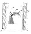
- FIG. 1is a perspective view of a delivery catheter assembly in accordance with the present invention, wherein the delivery catheter assembly is located within a vessel in an angled configuration;
- FIG. 2is a perspective view of the delivery catheter assembly of FIG. 1, wherein the inner sheath of the catheter assembly is advanced from the outer sheath;
- FIG. 3is a perspective view of the delivery catheter assembly of FIG. 1, wherein the inner sheath is in a fully extended position within the vessel;
- FIG. 4is a perspective view of the delivery catheter assembly of FIG. 1 at the beginning of the process of inserting a fastener to secure a surgical component to a vessel wall;
- FIG. 5is a perspective view of the delivery catheter assembly of FIG. 1 during the process of inserting a fastener to secure the surgical component to the vessel wall;
- FIG. 6is a perspective view of the delivery catheter assembly of FIG. 1 after the fastener assembly has secured the surgical component to the vessel wall;
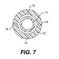
- FIG. 7is a cross sectional view of the outer sheath 12 of the catheter assembly in accordance with the present invention.
- FIGS. 8 a-eare perspective views of the delivery catheter assembly of FIG. 1, including multiple fastener assemblies during the process of inserting a fastener assembly to secure the surgical component to the vessel wall;
- FIGS. 9 a-dare perspective views of the delivery catheter assembly of FIG. 8 in accordance with another embodiment of the present invention.
- FIG. 10illustrates a dilating tip according to an embodiment of the present invention.
- FIG. 11illustrates a dilating tip according to an alternative embodiment of the present invention.
- the delivery catheter assembly 10will now be described in connection with FIGS. 1-6.
- the delivery catheter assembly 10includes an inner sheath 11 and an outer sheath 12 .
- An insertion assembly 13is located within the inner sheath 11 , as shown in FIG. 1 .
- the insertion assembly 13preferably creates an aperture within a surgical component 1 and a vessel 2 , as shown in FIGS. 4-6, such that a fastener assembly 3 may be inserted through the aperture to secure the surgical component 1 to the vessel 2 , as shown in FIG. 6 .
- more than one fastener assembly 3may be contained in the inner sheath 11 aligned co-linearly in a distal-proximate orientation either located outside the insertion assembly 13 or within the insertion assembly 13 .
- the fastener assembly 3is preferably a flexible fastener assembly that applies a force to secure the surgical component 1 to the vessel 2 , as disclosed in the following U.S. patent applications: U.S. Provisional Patent Application No. 60/181,230, filed Feb. 9, 2000; U.S. patent application Ser. No. 09/442,768, filed Nov. 18, 1999; U.S. patent application Ser. No. 09/213,233, filed Dec. 17,1998, now U.S. Pat. No. 5,997,556; U.S. patent application Ser. No. 08/958,524, filed Oct. 27,1997, now U.S. Pat. No.5,957,940, U.S. patent application Ser. No. 08/896,415, filed Jul. 18,1997, now U.S. Pat. No. 5,944,750; and U.S. Provisional Patent Application No. 60/051,209, filed Jun. 30, 1997.
- the subject matter of these patent applicationsis incorporated herein specifically by reference.
- the inner sheath 11 of the delivery catheter assembly 10is movable with respect to the outer sheath 12 .
- the delivery catheter assembly 10is advanced to the surgical procedure specific area within the vessel 2 through a delivery sheath 4 .
- the delivery catheter assembly 10 and the delivery sheath 4have sufficient length such that the assembly 10 and sheath 4 may extend from either an axillary incision, a brachial incision or a femoral or common iliac arteriotomy to the procedure specific area within the vessel 2 .
- the catheter assembly 10has an end portion 121 having an angular configuration, as shown in FIGS. 1-6.
- the catheter assembly 10is flexible such that it may be advanced through the delivery sheath 4 .
- the outer sheath 12is formed from a suitable material that permits the end portion 121 to be flexed to maintain its angular configuration during the process of inserting a fastener 3 through the surgical component 1 and the vessel 2 , as show in FIGS. 1-6.
- the outer sheath 12preferably has a braided construction.
- the angular configuration of the end portion 121is achieved with at least one pull wire 14 positioned within the outer sheath 12 , as shown in FIG. 7 .
- the end portion of the outer sheath 12is deflected when the at least one pull wire 14 is tensioned.
- Each of the at least one wire 14extends through the outer sheath 12 .
- a free end portion of each pull wire 14exits the outer sheath 12 at a point that is located outside the body of the patient during the surgical procedure.
- the free end portion of the pull wire 14maybe manipulated/tensioned by the surgeon by hand. Alternatively, the free end portion of the pull wire 14 may be connected to a control assembly (not shown) for operation by the surgeon.
- Each pull wire 14is separated from the exterior of the deflectable tip section by a wall thickness less than 0.010′′. This permits deflection of the end portion of the outer sheath 12 when one of the pull wires 14 are tensioned.
- Each pull wire 14is preferably surrounded by an elastomeric sleeve of a polymeric material of a recoverable elongation of 500-1000%. Examples of such materials are polyurethane and silicone elastomer.
- the pull wires 14are protected from tissue abrasion by the elastomeric sleeve. Further, this construction prevents the release of fragments in the vessel in the event a pull wire fails.
- the failure of a pull wiredoes not produce a permanently curved shape that would be difficult to remove from the vessel.
- the elastomeric sleeve, the inner sheath 11 and the outer sheath 12provide a driving force that allows the tip to straighten once when the tension on the pull wire 14 is relaxed.
- the outer sheath 12preferably has a braided construction with increasing less durometer in the distal direction in order to optimize torque transmission.
- the lesser durometer sections of the outer sheath 12correspond to areas where the catheter is expected to negotiate bends in the anatomy. These more flexible areas of the outer sheath 12 can more efficiently transmit torque around a bend than stiffer high durometer areas.
- Typical materials used to form the outer sheath 12may be polyether amide compounds and polyurethane, or any other suitable material.
- Each pull wire 14permits deflection of the end portion of the outer sheath 12 in a single direction.
- the outer sheath 12includes a plurality of pull wires 14 , as shown in FIG.
- the wire 14extends out of the circumferential envelope of catheter diameter when the wire 14 is under tension to effect tip deflection.
- the outer sheath 12being deflected out of the normal diameter of the catheter.
- the delivery sheath 4 and delivery catheter assembly 10are advanced through the vessel 2 to the procedure specific area within the vessel 2 .
- the catheter assembly 10is the extended such that the end portion 121 of the catheter assembly 10 extends from the sheath 4 .
- the end portion 121then assumes its angular configuration, as shown in FIG. 1, by manipulating one of the pull wires 14 .
- the inner sheath 11is then advanced such that it extends to contact the surgical component 1 , as shown in FIG. 2 .
- the inner sheath 11is further advanced such that the outer sheath 12 contacts the surgical component 1 at a location opposite to the point of contact of the inner sheath 11 , as shown in FIG. 3 .
- the inner sheath 11is still further advanced such that it applies sufficient pressure on the surgical component 1 to push the surgical component 1 firmly against the vessel 2 , as shown in FIG. 4 .
- the insertion assembly 13is then activated and advanced to create an aperture in the surgical component 1 and the vessel 2 through which the fastener assembly 3 extends, as shown in FIG. 5 .
- the insertion assembly 13preferably includes a laser fiber assembly that is capable of creating an aperture through which the fastener assembly 3 is inserted to secure the surgical component 1 to the vessel 2 .
- the insertion assembly 13 in accordance with the present inventionis not limited to a laser fiber assembly; rather, a piezoelectric penetration device, as disclosed in U.S. Pat. Nos. 5,997,556, 5,957,940 and 5,944,750 and the embodiments disclosed therein are considered to be well within the scope of the present invention.
- the insertion assembly 13advances through the aperture that it has created as well as a fastener assembly 3 , as shown in FIG. 5 .
- the advancement of the fastener assembly 3may occur simultaneously with the advancement of the insertion assembly 13 , or may follow the advancement of the insertion assembly 13 .
- the fastener assembly 3may be located around the outside of insertion assembly 13 , or the fastener assembly 3 may be located within a hollow core of insertion assembly 13 .
- the insertion assembly 13advances a fixed distance through and beyond the vessel 2 such that one portion of the fastener assembly 3 is located on one side of the vessel 2 and another portion of the fastener assembly 3 is located on an opposite side of the surgical component 1 .
- the insertion assembly 13 and the inner sheath 11are then retracted to the position shown in FIG. 6 leaving behind the fastener assembly 3 in an inserted position.
- the catheter assembly 10is then manipulated within the vessel 2 to another location whereby the process of inserting a fastener assembly 3 is repeated to secure the surgical component 1 to the vessel 2 .
- the catheter assembly 10may be manipulated by releasing the tension in one of the pull wires 14 and applying tension to another pull wire 14 . Thus changing the deflection of the outer sheath 12 .
- the operation of the catheter assembly 10is controlled by a controller, such as for example, a hand controller (not shown) located outside the body.
- a controllersuch as for example, a hand controller (not shown) located outside the body.
- the fastener assembly 3is designed such that it is possible to place a string of fastener assemblies 3 in a continuous head to tail fashion within the inner sheath 11 as shown in FIG. 8 .
- This arrangementprovides a method of sequentially dispensing multiple fastener assemblies 3 to attach the surgical component 1 to the vessel 2 .
- the methods described hereinpermit more than one fastener assembly 3 to be contained in the inner sheath 11 and to be sequentially advanced into the surgical component 1 and vessel 2 .
- the fastener assemblies 3may be deployed from around the insertion assembly 13 , or may be deployed from within a hollow insertion assembly 13 .
- FIG. 8illustrates a method according to the present invention.
- FIG. 8 adepicts the positioning of the delivery catheter assembly in preparation for employing the fastening assembly 3 .
- FIG. 8 billustrates the creation of a treatment specific hole in the surgical component 1 and vessel 2 by an insertion assembly 13 .
- a fastener assembly 3may advance simultaneously with the insertion assembly 13 , or may advance into the treatment specific hole following the advancement, and prior to the retraction, of the insertion assembly 13 .
- the insertion assembly 13is retracted as shown in FIG. 8 c .
- a backstop tube 31located at the proximal end of the string of fastener assemblies 3 , holds the linear position of the fastener assemblies 3 and maintains their position while the insertion assembly 13 is retracted. Upon retraction of the insertion assembly 13 the fastener assembly 3 assumes a secondary orientation, securely attaching the surgical component 1 to the vessel 2 as shown in FIGS. 8 c and d .
- FIG. 8 eillustrates a view of the attached fastener assembly from the outside of the vessel.
- FIG. 9illustrates an alternative method for advancing multiple fastener assemblies 3 in relation to the insertion assembly 13 according to an embodiment of the present invention.
- the methodis similar to that described in FIGS. 8 a-d .
- This methodincorporates a pusher tube assembly 32 and an o-ring assembly 33 .
- the pusher tube assembly 32is responsible for maintaining the position of each fastener assembly 3 .
- the pusher tube assembly 32further includes spring loaded tabs 321 that seat securely to the proximal edge of each fastener assembly 3 .
- the spring loaded tabs 321engage an o-ring assembly 33 which ensures that a positive and reproducible engagement takes place between the pusher tube 32 and the edge of the fastener assembly 3 .
- FIG. 9illustrates two spring loaded tabs 321 per fastener assembly 3 .
- the spring loaded tabs 321open during fastener assembly 3 advancement thereby allowing the next fastener assembly 3 into position.
- the above methodsdescribe an embodiment of the present invention in which the fastener assemblies 3 are loaded as a continuous string in which the head of one fastener assembly 3 immediately abuts the tail of another fastener assembly 3 .
- the fastener assemblies 3may be separated from one another at the point of deployment by any number of means. These means include, but are not limited to, those means discussed above, as well as retracting the string of fastener assemblies 3 once the deployed fastener is correctly positioned within the surgical component 1 and vessel 2 such that a thin connecting membrane between the deployed fastener assembly 3 and the next fastener assembly 3 located in the inner sheath 11 is sheared.
- Methods of shearingmay include, but are not limited to, mechanical force, application of an appropriately controlled electrical pulse, the application of heat, or by dissolving a temporary connecting membrane.
- the fastener assembly 3 inserted into the surgical component 1 and the vessel 2may be held in place by a number of different methods, including but not limited to, threading, bonding, rehydration, thermal changes, deformation, expansion, friction, or torsion.
- FIGS. 8-11illustrate an embodiment of the fastener assembly 3 according to the present invention.
- a method of facilitating the insertion of fastener assemblies 3includes a dilating tip 34 that is secured to the leading edge of the fastener assembly 3 . During penetration of the surgical component 1 and vessel 2 the presence of dilating tip 34 may reduce the force required to insert the fastener assembly 3 .
- FIGS. 10 and 11illustrate a dilating tip 34 illustrating at least one cutting edge 341 on the leading end of the dilating tip 34 .
- the cutting edge 341facilitates the insertion of fastener assembly 3 into the surgical component 1 and vessel 2 .
- the cutting edge 341may be ground into the surgical fastener 3 or can be a feature molded into fastener assembly 3 .
- the dilating tip 34may be constructed of commonly known surgical implant materials including, but not limited to, bioresorbables, metals such as MP-35N titianium, etc., and ultrahigh molecular weight polyurethane, UHMWPE, or any other suitable material.
- the dilating tips 34are designed to be securely fixed to the leading edge fastener assembly 3 .
- a surgical component 1which may be a graft assembly
- a vesselwhich may be an aortic wall
- the present inventionis not limited to securing a surgical component to a vessel; rather, it is contemplated that the present invention may be used in connection with securing a vessel to another vessel, tissue to tissue, surgical components to surgical components and any variations thereof.
- the delivery catheter assembly 10may be used to deliver and/or advance other surgical devices including but not limited to a visualization device of other monitoring equipment, rather than the insertion assembly 13 . Accordingly, the preferred embodiments of the invention as set forth herein are intended to be illustrative, not limiting. Various changes may be made without departing from the spirit and scope of the invention as defined in the following claims.
Landscapes
- Health & Medical Sciences (AREA)
- Life Sciences & Earth Sciences (AREA)
- Surgery (AREA)
- Heart & Thoracic Surgery (AREA)
- Engineering & Computer Science (AREA)
- Biomedical Technology (AREA)
- Nuclear Medicine, Radiotherapy & Molecular Imaging (AREA)
- Medical Informatics (AREA)
- Molecular Biology (AREA)
- Animal Behavior & Ethology (AREA)
- General Health & Medical Sciences (AREA)
- Public Health (AREA)
- Veterinary Medicine (AREA)
- Surgical Instruments (AREA)
Abstract
Description
Claims (33)
Priority Applications (2)
| Application Number | Priority Date | Filing Date | Title |
|---|---|---|---|
| US09/783,313US6607555B2 (en) | 2000-02-15 | 2001-02-15 | Delivery catheter assembly and method of securing a surgical component to a vessel during a surgical procedure |
| US10/411,135US7101366B2 (en) | 2000-02-15 | 2003-04-11 | Apparatus and method for performing a surgical procedure |
Applications Claiming Priority (2)
| Application Number | Priority Date | Filing Date | Title |
|---|---|---|---|
| US18254300P | 2000-02-15 | 2000-02-15 | |
| US09/783,313US6607555B2 (en) | 2000-02-15 | 2001-02-15 | Delivery catheter assembly and method of securing a surgical component to a vessel during a surgical procedure |
Related Child Applications (1)
| Application Number | Title | Priority Date | Filing Date |
|---|---|---|---|
| US10/411,135Continuation-In-PartUS7101366B2 (en) | 2000-02-15 | 2003-04-11 | Apparatus and method for performing a surgical procedure |
Publications (2)
| Publication Number | Publication Date |
|---|---|
| US20020026144A1 US20020026144A1 (en) | 2002-02-28 |
| US6607555B2true US6607555B2 (en) | 2003-08-19 |
Family
ID=22668917
Family Applications (1)
| Application Number | Title | Priority Date | Filing Date |
|---|---|---|---|
| US09/783,313Expired - Fee RelatedUS6607555B2 (en) | 2000-02-15 | 2001-02-15 | Delivery catheter assembly and method of securing a surgical component to a vessel during a surgical procedure |
Country Status (6)
| Country | Link |
|---|---|
| US (1) | US6607555B2 (en) |
| EP (1) | EP1255579A1 (en) |
| JP (1) | JP2003535621A (en) |
| AU (2) | AU2001238270B2 (en) |
| CA (1) | CA2400196A1 (en) |
| WO (1) | WO2001060432A1 (en) |
Cited By (46)
| Publication number | Priority date | Publication date | Assignee | Title |
|---|---|---|---|---|
| US20030208211A1 (en)* | 2002-05-01 | 2003-11-06 | Juergen Kortenbach | Tissue fastening devices and related insertion tools and methods |
| US20040002679A1 (en)* | 2000-02-15 | 2004-01-01 | Hugh Trout | Apparatus and method for performing a surgical procedure |
| US20040002718A1 (en)* | 2002-04-17 | 2004-01-01 | Hugh Trout | Apparatus and method for placement of surgical fasteners |
| US20040181242A1 (en)* | 2003-03-12 | 2004-09-16 | Stack Richard S. | Articulated suturing system |
| US20050090834A1 (en)* | 2003-10-23 | 2005-04-28 | Aptus Endosystems, Inc. | Prosthesis delivery systems and methods |
| US20050234541A1 (en)* | 2004-03-29 | 2005-10-20 | Hunt James B | Modifying fluid flow in a body vessel lumen to promote intraluminal flow-sensitive processes |
| US20060095116A1 (en)* | 2001-11-28 | 2006-05-04 | Aptus Endosystems, Inc. | Devices, systems, and methods for prosthesis delivery and implantation, including a prosthesis assembly |
| US20070021829A1 (en)* | 2001-11-28 | 2007-01-25 | Aptus Endosystems, Inc. | Endovascular aneurysm repair method |
| US20070073389A1 (en)* | 2001-11-28 | 2007-03-29 | Aptus Endosystems, Inc. | Endovascular aneurysm devices, systems, and methods |
| US20070083100A1 (en)* | 2005-07-20 | 2007-04-12 | Sebastian Schulz-Stubner | Ventriculostomy Catheter with In Situ Ultrasound Capability |
| US20080294231A1 (en)* | 2007-05-16 | 2008-11-27 | Boston Scientific Scimed, Inc. | Stent Delivery Catheter |
| US20090082852A1 (en)* | 2001-06-04 | 2009-03-26 | Aptus Endosystems, Inc. | Catheter-based fastener implantation apparatus and methods |
| US20090157048A1 (en)* | 2007-12-18 | 2009-06-18 | Boston Scientific Scimed, Inc. | Spiral cut hypotube |
| US7553323B1 (en) | 2004-01-08 | 2009-06-30 | Perez Juan I | Steerable endovascular graft delivery system |
| US20090177185A1 (en)* | 2008-01-03 | 2009-07-09 | Boston Scientific Scimed, Inc. | Cut tubular members for a medical device and methods for making and using the same |
| US20100094400A1 (en)* | 2001-11-28 | 2010-04-15 | Aptus Endosystems, Inc. | Devices, systems, and methods for prosthesis delivery and implantation |
| US7708181B2 (en) | 2008-03-18 | 2010-05-04 | Barosense, Inc. | Endoscopic stapling devices and methods |
| US20100204774A1 (en)* | 2006-03-06 | 2010-08-12 | Boston Scientific Scimed, Inc. | Stent delivery catheter |
| US20100280529A1 (en)* | 2009-05-04 | 2010-11-04 | Barosense, Inc. | Endoscopic implant system and method |
| US7892292B2 (en) | 2001-08-27 | 2011-02-22 | Synecor, Llc | Positioning tools and methods for implanting medical devices |
| US7934631B2 (en) | 2008-11-10 | 2011-05-03 | Barosense, Inc. | Multi-fire stapling systems and methods for delivering arrays of staples |
| US7981162B2 (en) | 2001-08-27 | 2011-07-19 | Barosense, Inc. | Satiation devices and methods |
| US8029455B2 (en) | 2003-01-16 | 2011-10-04 | Barosense, Inc. | Satiation pouches and methods of use |
| US8109895B2 (en) | 2006-09-02 | 2012-02-07 | Barosense, Inc. | Intestinal sleeves and associated deployment systems and methods |
| US20120123510A1 (en)* | 2010-11-15 | 2012-05-17 | Endovascular Development AB | Method of positioning a tubular element in a blood vessel of a person |
| US8206456B2 (en) | 2003-10-10 | 2012-06-26 | Barosense, Inc. | Restrictive and/or obstructive implant system for inducing weight loss |
| US8231639B2 (en) | 2001-11-28 | 2012-07-31 | Aptus Endosystems, Inc. | Systems and methods for attaching a prosthesis within a body lumen or hollow organ |
| US8241202B2 (en) | 2004-04-26 | 2012-08-14 | Barosense, Inc. | Restrictive and/or obstructive implant for inducing weight loss |
| US8292827B2 (en) | 2005-12-12 | 2012-10-23 | Boston Scientific Scimed, Inc. | Micromachined medical devices |
| US8337566B2 (en) | 2002-04-08 | 2012-12-25 | Barosense, Inc. | Method and apparatus for modifying the exit orifice of a satiation pouch |
| US8469977B2 (en) | 2005-10-03 | 2013-06-25 | Barosense, Inc. | Endoscopic plication device and method |
| US8568488B2 (en) | 2001-08-27 | 2013-10-29 | Boston Scientific Scimed, Inc. | Satiation devices and methods |
| US8690897B2 (en) | 2001-11-28 | 2014-04-08 | Aptus Endosystems, Inc. | Devices, systems, and methods for prosthesis delivery and implantation, including the use of a fastener tool |
| US8784500B2 (en) | 2003-10-10 | 2014-07-22 | Boston Scientific Scimed, Inc. | Devices and methods for retaining a gastro-esophageal implant |
| US8945167B2 (en) | 2007-12-31 | 2015-02-03 | Boston Scientific Scimed, Inc. | Gastric space occupier systems and methods of use |
| US9023065B2 (en) | 2001-11-28 | 2015-05-05 | Aptus Endosystems, Inc. | Devices, systems, and methods for supporting tissue and/or structures within a hollow body organ |
| US9107727B2 (en) | 2001-08-27 | 2015-08-18 | Boston Scientific Scimed, Inc. | Satiation devices and methods |
| WO2015074066A3 (en)* | 2013-11-18 | 2015-10-29 | Lee Bolduc | Multi-fire fastener delivery system and method |
| US9314361B2 (en) | 2006-09-15 | 2016-04-19 | Boston Scientific Scimed, Inc. | System and method for anchoring stomach implant |
| US9339632B2 (en) | 2006-09-27 | 2016-05-17 | Boston Scientific Scimed, Inc. | Catheter shaft designs |
| US9456825B2 (en) | 2007-07-18 | 2016-10-04 | Boston Scientific Scimed, Inc. | Endoscopic implant system and method |
| US9545249B2 (en) | 2007-07-18 | 2017-01-17 | Boston Scientific Scimed, Inc. | Overtube introducer for use in endoscopic bariatric surgery |
| US10194905B2 (en) | 2001-11-28 | 2019-02-05 | Medtronic Vascular, Inc. | Devices, systems, and methods for endovascular staple and/or prosthesis delivery and implantation |
| US10456282B2 (en)* | 2017-04-06 | 2019-10-29 | Medtronic Vascular, Inc. | Delivery system for anchor and method |
| US11950778B2 (en) | 2010-05-21 | 2024-04-09 | Boston Scientific Scimed, Inc. | Tissue-acquisition and fastening devices and methods |
| US12440207B2 (en) | 2021-11-17 | 2025-10-14 | Boston Scientific Scimed, Inc. | Multi-fire stapling systems and methods for delivering arrays of staples |
Families Citing this family (8)
| Publication number | Priority date | Publication date | Assignee | Title |
|---|---|---|---|---|
| US20050070992A1 (en) | 2001-11-28 | 2005-03-31 | Aptus Endosystems, Inc. | Prosthesis systems and methods sized and configured for the receipt and retention of fasteners |
| US20090112303A1 (en)* | 2001-11-28 | 2009-04-30 | Lee Bolduc | Devices, systems, and methods for endovascular staple and/or prosthesis delivery and implantation |
| US20110087320A1 (en)* | 2001-11-28 | 2011-04-14 | Aptus Endosystems, Inc. | Devices, Systems, and Methods for Prosthesis Delivery and Implantation, Including a Prosthesis Assembly |
| US7322943B2 (en)* | 2001-12-21 | 2008-01-29 | Eva Corporation | Apparatus and method for the multi-axial placement of surgical fasteners |
| WO2003079935A1 (en) | 2002-03-18 | 2003-10-02 | Eva Corporation | Method and apparatus to attach an unsupported surgical component |
| EP1549378A4 (en)* | 2002-09-23 | 2009-03-18 | Eva Corp | Apparatus and method for reducing fluid loss during a surgical procedure |
| EP1572005A4 (en)* | 2002-12-16 | 2012-03-14 | Edrich Health Technologies Inc | Endovascular stapler |
| CA2713341C (en)* | 2008-02-05 | 2016-09-27 | Cvdevices, Llc | Steering engagement catheter devices, systems, and methods |
Citations (11)
| Publication number | Priority date | Publication date | Assignee | Title |
|---|---|---|---|---|
| US3978863A (en) | 1974-06-06 | 1976-09-07 | Bruce E. Fettel | Expanding tip embolectomy catheter with indicator balloon |
| US5037421A (en) | 1989-10-06 | 1991-08-06 | Coherent, Inc., Medical Group | Mid-infrared laser arthroscopic procedure |
| US5147354A (en) | 1988-08-19 | 1992-09-15 | Coherent, Inc. | Mid-infrared laser endoscope |
| US5462561A (en)* | 1993-08-05 | 1995-10-31 | Voda; Jan K. | Suture device |
| US5599305A (en) | 1994-10-24 | 1997-02-04 | Cardiovascular Concepts, Inc. | Large-diameter introducer sheath having hemostasis valve and removable steering mechanism |
| US5690117A (en) | 1995-03-20 | 1997-11-25 | Gilbert; John W. | Ultrasonic-fiberoptic imaging ventricular catheter |
| US5797905A (en) | 1994-08-08 | 1998-08-25 | E. P. Technologies Inc. | Flexible tissue ablation elements for making long lesions |
| US5938696A (en) | 1994-02-09 | 1999-08-17 | Boston Scientific Technology, Inc. | Bifurcated endoluminal prosthesis |
| US5944750A (en)* | 1997-06-30 | 1999-08-31 | Eva Corporation | Method and apparatus for the surgical repair of aneurysms |
| US5957940A (en)* | 1997-06-30 | 1999-09-28 | Eva Corporation | Fasteners for use in the surgical repair of aneurysms |
| US5997556A (en)* | 1997-06-30 | 1999-12-07 | Eva Corporation | Surgical fastener |
- 2001
- 2001-02-15WOPCT/US2001/004764patent/WO2001060432A1/enactiveApplication Filing
- 2001-02-15AUAU2001238270Apatent/AU2001238270B2/ennot_activeCeased
- 2001-02-15CACA002400196Apatent/CA2400196A1/ennot_activeAbandoned
- 2001-02-15USUS09/783,313patent/US6607555B2/ennot_activeExpired - Fee Related
- 2001-02-15EPEP01910687Apatent/EP1255579A1/ennot_activeWithdrawn
- 2001-02-15JPJP2001559526Apatent/JP2003535621A/enactivePending
- 2001-02-15AUAU3827001Apatent/AU3827001A/enactivePending
Patent Citations (12)
| Publication number | Priority date | Publication date | Assignee | Title |
|---|---|---|---|---|
| US3978863A (en) | 1974-06-06 | 1976-09-07 | Bruce E. Fettel | Expanding tip embolectomy catheter with indicator balloon |
| US5147354A (en) | 1988-08-19 | 1992-09-15 | Coherent, Inc. | Mid-infrared laser endoscope |
| US5147354B1 (en) | 1988-08-19 | 1997-10-14 | Coherent Inc | Mid-infrared laser endoscope |
| US5037421A (en) | 1989-10-06 | 1991-08-06 | Coherent, Inc., Medical Group | Mid-infrared laser arthroscopic procedure |
| US5462561A (en)* | 1993-08-05 | 1995-10-31 | Voda; Jan K. | Suture device |
| US5938696A (en) | 1994-02-09 | 1999-08-17 | Boston Scientific Technology, Inc. | Bifurcated endoluminal prosthesis |
| US5797905A (en) | 1994-08-08 | 1998-08-25 | E. P. Technologies Inc. | Flexible tissue ablation elements for making long lesions |
| US5599305A (en) | 1994-10-24 | 1997-02-04 | Cardiovascular Concepts, Inc. | Large-diameter introducer sheath having hemostasis valve and removable steering mechanism |
| US5690117A (en) | 1995-03-20 | 1997-11-25 | Gilbert; John W. | Ultrasonic-fiberoptic imaging ventricular catheter |
| US5944750A (en)* | 1997-06-30 | 1999-08-31 | Eva Corporation | Method and apparatus for the surgical repair of aneurysms |
| US5957940A (en)* | 1997-06-30 | 1999-09-28 | Eva Corporation | Fasteners for use in the surgical repair of aneurysms |
| US5997556A (en)* | 1997-06-30 | 1999-12-07 | Eva Corporation | Surgical fastener |
Cited By (110)
| Publication number | Priority date | Publication date | Assignee | Title |
|---|---|---|---|---|
| US7101366B2 (en)* | 2000-02-15 | 2006-09-05 | Eva Corporation | Apparatus and method for performing a surgical procedure |
| US20040002679A1 (en)* | 2000-02-15 | 2004-01-01 | Hugh Trout | Apparatus and method for performing a surgical procedure |
| US20090082852A1 (en)* | 2001-06-04 | 2009-03-26 | Aptus Endosystems, Inc. | Catheter-based fastener implantation apparatus and methods |
| US9968353B2 (en) | 2001-06-04 | 2018-05-15 | Medtronic Vascular, Inc. | Catheter based fastener implantation apparatus and methods |
| US8992457B2 (en) | 2001-08-27 | 2015-03-31 | Boston Scientific Scimed, Inc. | Gastrointestinal implants |
| US9788984B2 (en) | 2001-08-27 | 2017-10-17 | Boston Scientific Scimed, Inc. | Satiation devices and methods |
| US8568488B2 (en) | 2001-08-27 | 2013-10-29 | Boston Scientific Scimed, Inc. | Satiation devices and methods |
| US7981162B2 (en) | 2001-08-27 | 2011-07-19 | Barosense, Inc. | Satiation devices and methods |
| US8784354B2 (en) | 2001-08-27 | 2014-07-22 | Boston Scientific Scimed, Inc. | Positioning tools and methods for implanting medical devices |
| US8845753B2 (en) | 2001-08-27 | 2014-09-30 | Boston Scientific Scimed, Inc. | Satiation devices and methods |
| US9107727B2 (en) | 2001-08-27 | 2015-08-18 | Boston Scientific Scimed, Inc. | Satiation devices and methods |
| US10080677B2 (en) | 2001-08-27 | 2018-09-25 | Boston Scientific Scimed, Inc. | Satiation devices and methods |
| US9138340B2 (en) | 2001-08-27 | 2015-09-22 | Boston Scientific Scimed, Inc. | Gastro-esophageal implants |
| US9180036B2 (en) | 2001-08-27 | 2015-11-10 | Boston Scientific Scimed, Inc. | Methods for implanting medical devices |
| US9872786B2 (en) | 2001-08-27 | 2018-01-23 | Boston Scientific Scimed, Inc. | Gastro-esophageal implants |
| US9844453B2 (en) | 2001-08-27 | 2017-12-19 | Boston Scientific Scimed, Inc. | Positioning tools and methods for implanting medical devices |
| US9254214B2 (en) | 2001-08-27 | 2016-02-09 | Boston Scientific Scimed, Inc. | Satiation devices and methods |
| US7892292B2 (en) | 2001-08-27 | 2011-02-22 | Synecor, Llc | Positioning tools and methods for implanting medical devices |
| US9358144B2 (en) | 2001-08-27 | 2016-06-07 | Boston Scientific Scimed, Inc. | Gastrointestinal implants |
| US20060095116A1 (en)* | 2001-11-28 | 2006-05-04 | Aptus Endosystems, Inc. | Devices, systems, and methods for prosthesis delivery and implantation, including a prosthesis assembly |
| US20070021829A1 (en)* | 2001-11-28 | 2007-01-25 | Aptus Endosystems, Inc. | Endovascular aneurysm repair method |
| US7637932B2 (en) | 2001-11-28 | 2009-12-29 | Aptus Endosystems, Inc. | Devices, systems, and methods for prosthesis delivery and implantation |
| US10299791B2 (en) | 2001-11-28 | 2019-05-28 | Medtronic Vascular, Inc. | Endovascular aneurysm repair system |
| US20100094400A1 (en)* | 2001-11-28 | 2010-04-15 | Aptus Endosystems, Inc. | Devices, systems, and methods for prosthesis delivery and implantation |
| US8092519B2 (en) | 2001-11-28 | 2012-01-10 | Aptus Endosystems, Inc. | Endovascular aneurysm repair system |
| US9320503B2 (en) | 2001-11-28 | 2016-04-26 | Medtronic Vascular, Inc. | Devices, system, and methods for guiding an operative tool into an interior body region |
| US9808250B2 (en) | 2001-11-28 | 2017-11-07 | Medtronic Vascular, Inc. | Systems and methods for attaching a prosthesis within a body lumen or hollow organ |
| US10595867B2 (en) | 2001-11-28 | 2020-03-24 | Medtronic Vascular, Inc. | Systems and methods for attaching a prosthesis within a body lumen or hollow organ |
| US7828838B2 (en) | 2001-11-28 | 2010-11-09 | Aptus Endosystems, Inc. | Devices, systems, and methods for prosthesis delivery and implantation, including a prosthesis assembly |
| US9320591B2 (en) | 2001-11-28 | 2016-04-26 | Medtronic Vascular, Inc. | Devices, systems, and methods for prosthesis delivery and implantation, including the use of a fastener tool |
| US9744021B2 (en) | 2001-11-28 | 2017-08-29 | Medtronic Vascular, Inc. | Devices, systems, and methods for prosthesis delivery and implantation, including the use of a fastener tool |
| US9320589B2 (en) | 2001-11-28 | 2016-04-26 | Medtronic Vascular, Inc. | Endovascular aneurysm repair system |
| US8231639B2 (en) | 2001-11-28 | 2012-07-31 | Aptus Endosystems, Inc. | Systems and methods for attaching a prosthesis within a body lumen or hollow organ |
| US20070073389A1 (en)* | 2001-11-28 | 2007-03-29 | Aptus Endosystems, Inc. | Endovascular aneurysm devices, systems, and methods |
| US10098770B2 (en) | 2001-11-28 | 2018-10-16 | Medtronic Vascular, Inc. | Endovascular aneurysm devices, systems, and methods |
| US10357230B2 (en) | 2001-11-28 | 2019-07-23 | Medtronic Vascular, Inc. | Devices, system, and methods for guiding an operative tool into an interior body region |
| US9023065B2 (en) | 2001-11-28 | 2015-05-05 | Aptus Endosystems, Inc. | Devices, systems, and methods for supporting tissue and/or structures within a hollow body organ |
| US10194905B2 (en) | 2001-11-28 | 2019-02-05 | Medtronic Vascular, Inc. | Devices, systems, and methods for endovascular staple and/or prosthesis delivery and implantation |
| US8690897B2 (en) | 2001-11-28 | 2014-04-08 | Aptus Endosystems, Inc. | Devices, systems, and methods for prosthesis delivery and implantation, including the use of a fastener tool |
| US8685044B2 (en) | 2001-11-28 | 2014-04-01 | Aptus Endosystems, Inc. | Systems and methods for attaching a prosthesis with a body lumen or hollow organ |
| US7959663B2 (en) | 2001-11-28 | 2011-06-14 | Aptus Endosystems, Inc. | Endovascular aneurysm repair method |
| US8083752B2 (en) | 2001-11-28 | 2011-12-27 | Aptus Endosystems, Inc. | Endovascular aneurysm repair systems and methods |
| US8337566B2 (en) | 2002-04-08 | 2012-12-25 | Barosense, Inc. | Method and apparatus for modifying the exit orifice of a satiation pouch |
| US20040002718A1 (en)* | 2002-04-17 | 2004-01-01 | Hugh Trout | Apparatus and method for placement of surgical fasteners |
| US7811295B2 (en) | 2002-05-01 | 2010-10-12 | Boston Scientific Scimed, Inc. | Tissue fastening devices and related insertion tools and methods |
| US20070021756A1 (en)* | 2002-05-01 | 2007-01-25 | Scimed Life Systems, Inc. | Tissue fastening devices and related insertion tools and methods |
| US7077850B2 (en) | 2002-05-01 | 2006-07-18 | Scimed Life Systems, Inc. | Tissue fastening devices and related insertion tools and methods |
| US9433410B2 (en) | 2002-05-01 | 2016-09-06 | Boston Scientific Scimed, Inc. | Tissue fastening devices and related insertion tools and methods |
| US20030208211A1 (en)* | 2002-05-01 | 2003-11-06 | Juergen Kortenbach | Tissue fastening devices and related insertion tools and methods |
| US8029455B2 (en) | 2003-01-16 | 2011-10-04 | Barosense, Inc. | Satiation pouches and methods of use |
| US20040181242A1 (en)* | 2003-03-12 | 2004-09-16 | Stack Richard S. | Articulated suturing system |
| US20070083255A1 (en)* | 2003-07-21 | 2007-04-12 | Aptus Endosystems, Inc. | Prosthesis delivery systems and methods |
| US8080050B2 (en) | 2003-07-21 | 2011-12-20 | Aptus Endosystems, Inc. | Prosthesis delivery systems and methods |
| US9445791B2 (en) | 2003-10-10 | 2016-09-20 | Boston Scientific Scimed, Inc. | Systems and methods related to gastro-esophageal implants |
| US10285836B2 (en) | 2003-10-10 | 2019-05-14 | Boston Scientific Scimed, Inc. | Systems and methods related to gastro-esophageal implants |
| US8206456B2 (en) | 2003-10-10 | 2012-06-26 | Barosense, Inc. | Restrictive and/or obstructive implant system for inducing weight loss |
| US9180035B2 (en) | 2003-10-10 | 2015-11-10 | Boston Scientific Scimed, Inc. | Devices and methods for retaining a gastro-esophageal implant |
| US9248038B2 (en) | 2003-10-10 | 2016-02-02 | Boston Scientific Scimed, Inc. | Methods for retaining a gastro-esophageal implant |
| US8784500B2 (en) | 2003-10-10 | 2014-07-22 | Boston Scientific Scimed, Inc. | Devices and methods for retaining a gastro-esophageal implant |
| US20050090834A1 (en)* | 2003-10-23 | 2005-04-28 | Aptus Endosystems, Inc. | Prosthesis delivery systems and methods |
| US7147657B2 (en) | 2003-10-23 | 2006-12-12 | Aptus Endosystems, Inc. | Prosthesis delivery systems and methods |
| US7553323B1 (en) | 2004-01-08 | 2009-06-30 | Perez Juan I | Steerable endovascular graft delivery system |
| US20050234541A1 (en)* | 2004-03-29 | 2005-10-20 | Hunt James B | Modifying fluid flow in a body vessel lumen to promote intraluminal flow-sensitive processes |
| US7449027B2 (en) | 2004-03-29 | 2008-11-11 | Cook Incorporated | Modifying fluid flow in a body vessel lumen to promote intraluminal flow-sensitive processes |
| US8241202B2 (en) | 2004-04-26 | 2012-08-14 | Barosense, Inc. | Restrictive and/or obstructive implant for inducing weight loss |
| US10098773B2 (en) | 2004-04-26 | 2018-10-16 | Boston Scientific Scimed, Inc. | Restrictive and/or obstructive implant for inducing weight loss |
| US20070083100A1 (en)* | 2005-07-20 | 2007-04-12 | Sebastian Schulz-Stubner | Ventriculostomy Catheter with In Situ Ultrasound Capability |
| US8469977B2 (en) | 2005-10-03 | 2013-06-25 | Barosense, Inc. | Endoscopic plication device and method |
| US9055942B2 (en) | 2005-10-03 | 2015-06-16 | Boston Scienctific Scimed, Inc. | Endoscopic plication devices and methods |
| US10299796B2 (en) | 2005-10-03 | 2019-05-28 | Boston Scientific Scimed, Inc. | Endoscopic plication devices and methods |
| US8292827B2 (en) | 2005-12-12 | 2012-10-23 | Boston Scientific Scimed, Inc. | Micromachined medical devices |
| US20100204774A1 (en)* | 2006-03-06 | 2010-08-12 | Boston Scientific Scimed, Inc. | Stent delivery catheter |
| US9687334B2 (en) | 2006-09-02 | 2017-06-27 | Boston Scientific Scimed, Inc. | Intestinal sleeves and associated deployment systems and methods |
| US8109895B2 (en) | 2006-09-02 | 2012-02-07 | Barosense, Inc. | Intestinal sleeves and associated deployment systems and methods |
| US9314361B2 (en) | 2006-09-15 | 2016-04-19 | Boston Scientific Scimed, Inc. | System and method for anchoring stomach implant |
| US10315018B2 (en) | 2006-09-27 | 2019-06-11 | Boston Scientific Scimed Inc. | Catheter shaft designs |
| US9339632B2 (en) | 2006-09-27 | 2016-05-17 | Boston Scientific Scimed, Inc. | Catheter shaft designs |
| US20080294231A1 (en)* | 2007-05-16 | 2008-11-27 | Boston Scientific Scimed, Inc. | Stent Delivery Catheter |
| US7981148B2 (en) | 2007-05-16 | 2011-07-19 | Boston Scientific Scimed, Inc. | Stent delivery catheter |
| US10537456B2 (en) | 2007-07-18 | 2020-01-21 | Boston Scientific Scimed, Inc. | Endoscopic implant system and method |
| US9456825B2 (en) | 2007-07-18 | 2016-10-04 | Boston Scientific Scimed, Inc. | Endoscopic implant system and method |
| US9545249B2 (en) | 2007-07-18 | 2017-01-17 | Boston Scientific Scimed, Inc. | Overtube introducer for use in endoscopic bariatric surgery |
| US20090157048A1 (en)* | 2007-12-18 | 2009-06-18 | Boston Scientific Scimed, Inc. | Spiral cut hypotube |
| US8945167B2 (en) | 2007-12-31 | 2015-02-03 | Boston Scientific Scimed, Inc. | Gastric space occupier systems and methods of use |
| US9227037B2 (en) | 2008-01-03 | 2016-01-05 | Boston Scientific Scimed, Inc. | Cut tubular members for a medical device and methods for making and using the same |
| US20090177185A1 (en)* | 2008-01-03 | 2009-07-09 | Boston Scientific Scimed, Inc. | Cut tubular members for a medical device and methods for making and using the same |
| US8460213B2 (en) | 2008-01-03 | 2013-06-11 | Boston Scientific Scimed, Inc. | Cut tubular members for a medical device and methods for making and using the same |
| US7922062B2 (en) | 2008-03-18 | 2011-04-12 | Barosense, Inc. | Endoscopic stapling devices and methods |
| US7909223B2 (en) | 2008-03-18 | 2011-03-22 | Barosense, Inc. | Endoscopic stapling devices and methods |
| US8864008B2 (en) | 2008-03-18 | 2014-10-21 | Boston Scientific Scimed, Inc. | Endoscopic stapling devices and methods |
| US7708181B2 (en) | 2008-03-18 | 2010-05-04 | Barosense, Inc. | Endoscopic stapling devices and methods |
| US7721932B2 (en) | 2008-03-18 | 2010-05-25 | Barosense, Inc. | Endoscopic stapling devices and methods |
| US9636114B2 (en) | 2008-03-18 | 2017-05-02 | Boston Scientific Scimed, Inc. | Endoscopic stapling devices |
| US8020741B2 (en) | 2008-03-18 | 2011-09-20 | Barosense, Inc. | Endoscopic stapling devices and methods |
| US7913892B2 (en) | 2008-03-18 | 2011-03-29 | Barosense, Inc. | Endoscopic stapling devices and methods |
| US7909219B2 (en) | 2008-03-18 | 2011-03-22 | Barosense, Inc. | Endoscopic stapling devices and methods |
| US7909222B2 (en) | 2008-03-18 | 2011-03-22 | Barosense, Inc. | Endoscopic stapling devices and methods |
| US8747421B2 (en) | 2008-11-10 | 2014-06-10 | Boston Scientific Scimed, Inc. | Multi-fire stapling systems and methods for delivering arrays of staples |
| US11202627B2 (en) | 2008-11-10 | 2021-12-21 | Boston Scientific Scimed, Inc. | Multi-fire stapling systems and methods for delivering arrays of staples |
| US9451956B2 (en) | 2008-11-10 | 2016-09-27 | Boston Scientific Scimed, Inc. | Multi-fire stapling systems |
| US10368862B2 (en) | 2008-11-10 | 2019-08-06 | Boston Scientific Scimed, Inc. | Multi-fire stapling methods |
| US7934631B2 (en) | 2008-11-10 | 2011-05-03 | Barosense, Inc. | Multi-fire stapling systems and methods for delivering arrays of staples |
| US8961539B2 (en) | 2009-05-04 | 2015-02-24 | Boston Scientific Scimed, Inc. | Endoscopic implant system and method |
| US20100280529A1 (en)* | 2009-05-04 | 2010-11-04 | Barosense, Inc. | Endoscopic implant system and method |
| US11950778B2 (en) | 2010-05-21 | 2024-04-09 | Boston Scientific Scimed, Inc. | Tissue-acquisition and fastening devices and methods |
| US20120123510A1 (en)* | 2010-11-15 | 2012-05-17 | Endovascular Development AB | Method of positioning a tubular element in a blood vessel of a person |
| US8535371B2 (en)* | 2010-11-15 | 2013-09-17 | Endovascular Development AB | Method of positioning a tubular element in a blood vessel of a person |
| WO2015074066A3 (en)* | 2013-11-18 | 2015-10-29 | Lee Bolduc | Multi-fire fastener delivery system and method |
| US10456282B2 (en)* | 2017-04-06 | 2019-10-29 | Medtronic Vascular, Inc. | Delivery system for anchor and method |
| US12440207B2 (en) | 2021-11-17 | 2025-10-14 | Boston Scientific Scimed, Inc. | Multi-fire stapling systems and methods for delivering arrays of staples |
Also Published As
| Publication number | Publication date |
|---|---|
| JP2003535621A (en) | 2003-12-02 |
| AU3827001A (en) | 2001-08-27 |
| US20020026144A1 (en) | 2002-02-28 |
| AU2001238270B2 (en) | 2006-07-06 |
| CA2400196A1 (en) | 2001-08-23 |
| EP1255579A1 (en) | 2002-11-13 |
| WO2001060432A1 (en) | 2001-08-23 |
Similar Documents
| Publication | Publication Date | Title |
|---|---|---|
| US6607555B2 (en) | Delivery catheter assembly and method of securing a surgical component to a vessel during a surgical procedure | |
| AU2001238270A1 (en) | Delivery catheter assembly and method of securing a surgical component to a vessel during a surgical procedure | |
| US6520974B2 (en) | Surgical fastener | |
| US6602280B2 (en) | Delivery system and method for expandable intracorporeal device | |
| US20030195607A1 (en) | Method and apparatus to attach an unsupported surgical component | |
| AU2001234948A1 (en) | Surgical fastener | |
| US20070010875A1 (en) | Method and apparatus to attach an unsupported surgical component | |
| US20040098043A1 (en) | Delivery apparatus for use during a surgical procedure and method of using the same | |
| US7101366B2 (en) | Apparatus and method for performing a surgical procedure | |
| EP1229842A1 (en) | Heat activated surgical fastener | |
| EP1499263A2 (en) | Apparatus and method for performing a surgical procedure | |
| US7322992B2 (en) | Method of removing a fastener | |
| US7322943B2 (en) | Apparatus and method for the multi-axial placement of surgical fasteners | |
| US20040024362A1 (en) | Stabilizing surgical delivery apparatus and method of use | |
| JP2005523068A (en) | Apparatus and method for placing a surgical fastener | |
| US20200405512A1 (en) | Systems and methods for controlled release of stent barbs | |
| EP1897504A2 (en) | Surgical fastener |
Legal Events
| Date | Code | Title | Description |
|---|---|---|---|
| AS | Assignment | Owner name:EVA CORPORATION, MARYLAND Free format text:ASSIGNMENT OF ASSIGNORS INTEREST;ASSIGNOR:PATTERSON, FRANK;REEL/FRAME:013369/0252 Effective date:20020913 | |
| AS | Assignment | Owner name:EVA CORPORATION, MARYLAND Free format text:ASSIGNMENT OF ASSIGNORS INTEREST;ASSIGNORS:TANNER, HOWARD M.;TROUT, HUGH III;PATTERSON, FRANK;REEL/FRAME:013877/0139;SIGNING DATES FROM 20030129 TO 20030226 | |
| FPAY | Fee payment | Year of fee payment:4 | |
| AS | Assignment | Owner name:KELLEY DRYE & WARREN LLP, DISTRICT OF COLUMBIA Free format text:SECURITY AGREEMENT;ASSIGNOR:EVA CORPORATION;REEL/FRAME:020403/0822 Effective date:20070811 Owner name:KELLEY DRYE & WARREN LLP,DISTRICT OF COLUMBIA Free format text:SECURITY AGREEMENT;ASSIGNOR:EVA CORPORATION;REEL/FRAME:020403/0822 Effective date:20070811 | |
| FPAY | Fee payment | Year of fee payment:8 | |
| REMI | Maintenance fee reminder mailed | ||
| LAPS | Lapse for failure to pay maintenance fees | ||
| STCH | Information on status: patent discontinuation | Free format text:PATENT EXPIRED DUE TO NONPAYMENT OF MAINTENANCE FEES UNDER 37 CFR 1.362 | |
| FP | Lapsed due to failure to pay maintenance fee | Effective date:20150819 |