US6607539B1 - Electric endovascular implant depolyment system - Google Patents
Electric endovascular implant depolyment systemDownload PDFInfo
- Publication number
- US6607539B1 US6607539B1US09/860,717US86071701AUS6607539B1US 6607539 B1US6607539 B1US 6607539B1US 86071701 AUS86071701 AUS 86071701AUS 6607539 B1US6607539 B1US 6607539B1
- Authority
- US
- United States
- Prior art keywords
- graft
- resistive wire
- resistive
- conducting
- inferior
- Prior art date
- Legal status (The legal status is an assumption and is not a legal conclusion. Google has not performed a legal analysis and makes no representation as to the accuracy of the status listed.)
- Expired - Lifetime, expires
Links
Images


Classifications
- A—HUMAN NECESSITIES
- A61—MEDICAL OR VETERINARY SCIENCE; HYGIENE
- A61F—FILTERS IMPLANTABLE INTO BLOOD VESSELS; PROSTHESES; DEVICES PROVIDING PATENCY TO, OR PREVENTING COLLAPSING OF, TUBULAR STRUCTURES OF THE BODY, e.g. STENTS; ORTHOPAEDIC, NURSING OR CONTRACEPTIVE DEVICES; FOMENTATION; TREATMENT OR PROTECTION OF EYES OR EARS; BANDAGES, DRESSINGS OR ABSORBENT PADS; FIRST-AID KITS
- A61F2/00—Filters implantable into blood vessels; Prostheses, i.e. artificial substitutes or replacements for parts of the body; Appliances for connecting them with the body; Devices providing patency to, or preventing collapsing of, tubular structures of the body, e.g. stents
- A61F2/95—Instruments specially adapted for placement or removal of stents or stent-grafts
- A61F2002/9505—Instruments specially adapted for placement or removal of stents or stent-grafts having retaining means other than an outer sleeve, e.g. male-female connector between stent and instrument
- A61F2002/9511—Instruments specially adapted for placement or removal of stents or stent-grafts having retaining means other than an outer sleeve, e.g. male-female connector between stent and instrument the retaining means being filaments or wires
- A—HUMAN NECESSITIES
- A61—MEDICAL OR VETERINARY SCIENCE; HYGIENE
- A61F—FILTERS IMPLANTABLE INTO BLOOD VESSELS; PROSTHESES; DEVICES PROVIDING PATENCY TO, OR PREVENTING COLLAPSING OF, TUBULAR STRUCTURES OF THE BODY, e.g. STENTS; ORTHOPAEDIC, NURSING OR CONTRACEPTIVE DEVICES; FOMENTATION; TREATMENT OR PROTECTION OF EYES OR EARS; BANDAGES, DRESSINGS OR ABSORBENT PADS; FIRST-AID KITS
- A61F2250/00—Special features of prostheses classified in groups A61F2/00 - A61F2/26 or A61F2/82 or A61F9/00 or A61F11/00 or subgroups thereof
- A61F2250/0058—Additional features; Implant or prostheses properties not otherwise provided for
- A61F2250/0071—Additional features; Implant or prostheses properties not otherwise provided for breakable or frangible
Definitions
- This inventionrelates to a system and method for implanting a prosthesis, and more particularly, to a method for releasing a graft within a corporeal lumen.
- various fluid conducting body or corporeal lumenssuch as veins and arteries, may deteriorate or suffer trauma so that repair is necessary.
- various types of aneurysms or other deteriorative diseasesmay affect the ability of the lumen to conduct fluids.
- the damaged lumenis repairable only with the use of prosthesis such as an artificial vessel or graft.
- a prosthesis for intraluminal repair of a vesselIn intraluminal vessel repair, the prosthesis is advanced, in a radially compressed configuration, intraluminally through the vessel to the repair site using a delivery catheter. After being properly positioned at the repair site, the prosthesis is deployed in its expanded state within the vessel so that the prosthesis traverses the diseased portion to thereby repair the vessel.
- the prosthesisis secured within the vessel with hooks or staples that are either self-expanding upon deployment or are mechanically extended utilizing balloon dilation.
- One methodutilizes a sheath that holds the graft in a radially compressed configuration until it is removed therefrom.
- Another methodutilizes a mechanical release system composed of a retractable wire or control cords to release the graft from its compressed configuration.
- a third methodutilizes an electrolytic release system which employs a power-induced difference of potential to cause erosion of metal binding straps that hold a graft in a radially compressed state.
- a drawback of the sheath methodis the potential, in certain circumstances, for cocking or longitudinal movement of the graft caused when the sheath is retracted.
- a drawback of the mechanical release systemsis the potential for entanglement or a stress-induced failure when the release wire or cords are retracted or when the graft is advanced within the vessel.
- a drawback of the electrolytic release systemis that it can potentially take from 30 seconds to 5 minutes for the bindings retaining a graft to erode after application of the external voltage device.
- the present inventionprovides a new and improved device and method for releasing a graft within vasculature.
- the inventionemploys a resistive wire element which, when heated, severs bindings retaining a graft in a radially compressed configuration.
- the present systemcan be configured to release the graft bindings simultaneously or in any desired order.
- the present systemoperates to release a graft in an expedient manner and can be incorporated for use in existing prosthesis implant systems which utilize a sheath, mechanical release, or electrolytic erosion mechanism with only minor modifications to the delivery catheter and graft material.
- conducting wiresare used to deliver current to a resistive wire element which is placed in a looped configuration.
- the conducting wiresextend from external a patient's body to a position adjacent the resistive wire.
- the resistive wire elementcan be made of material such as nichrome.
- the conducting wirescan be made from standard circuitry wiring known in the art of medical electronics (i.e. copper with cladding).
- the resistive wire elementsevers the binding material which is threaded through the resistive wire loop. With the binding material cut, the graft is free to expand and secure itself to the vessel or be secured thereat by balloon dilation.
- the graftcan be tubular, bifurcated or modular.
- the graftembodies woven polyester, or another material suitable for placement in the body such as PTFE, that allows the binding material to be threaded through the graft to engage the resistive wire loop.
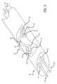
- FIG. 1is a perspective view, depicting a graft deployment system of the present invention with a portion of the graft material cut away to show the bindings threaded through the graft wall and resistive wire loops;
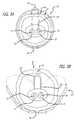
- FIG. 2Ais a cross-sectional view along line 2 — 2 of FIG. 1;
- FIG. 2Bis a cross-sectional view, depicting the system shown in FIG. 2A after an application of external voltage device;
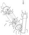
- FIG. 3is a perspective view, depicting the resistive wire loop formed by conducting wires and a resistive wire element
- FIG. 4is a perspective view depicting an alternate embodiment of the invention shown in FIG. 1 showing the bindings threaded through the resistive wire loops which pass through the graft wall;
- FIG. 5Ais a cross-sectional view along line 5 — 5 of FIG. 4;
- FIG. 5Bis a cross-sectional view, depicting the system shown in FIG. 5A after an application of external voltage device;
- FIG. 6is a perspective view depicting an alternate embodiment of the invention shown in FIG. 1 showing attachment systems at the superior and inferior ends of the graft;
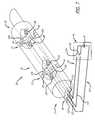
- FIG. 7is a perspective view depicting an alternative embodiment of the invention shown in FIG. 1 providing individual control of the graft bindings.
- the inventionis embodied in a device and method for releasing a graft from a radially compressed configuration into an expanded state within vasculature of a body.
- the implant deployment systemincludes a catheter and an expandable graft, and has associated therewith a method for releasing the graft within vasculature.
- the present inventionincludes a catheter with conducting wire lumens that facilitate application of an external voltage device to resistive wire elements in direct contact with graft bindings to thereby release the graft from a contracted state.
- a deployment system 10 for deploying a graft 15 within vasculatureincluding an inner shaft 20 having a pair of conducting wire lumens 21 , 22 , each of which are adapted to receive a conducting wire 25 , 26 .
- the systemfurther includes resistive wire elements 29 and an external power source 40 .
- the delivery system 10may be used in conjunction with a conventional catheter (not shown) which may include structure for receiving and overlaying the graft 15 during advancement of the system 10 through vasculature.
- the graft 15is held in a radially compressed configuration about the inner shaft 20 by bindings 27 .
- Each binding 27is looped around the graft 15 and placed into engagement with a resistive wire element 29 by threading the binding 27 through the resistive wire loop 30 formed between the conducting wires 25 , 26 and resistive wire element 29 . Thereafter, the ends of the bindings 27 are pulled tight to collapse the graft 15 and are stitched to the graft 15 and knotted 28 (See FIG. 2 A).
- One resistive wire element 29is provided for each binding 27 used to secure the expandable graft 15 in its compressed state.
- the resistive wire elements 29are contemplated to be made of a highly resistive metal that is heated to an elevated temperature when current is passed therethrough.
- the external power source 40includes an external voltage device 42 and a switch 41 allowing current to be delivered to the resistive wire elements 25 , 26 .
- the conducting wires 25 , 26 , resistive wire elements 29 and external power source 40cooperate to facilitate the release of the graft 15 so it may be accurately implanted in a lumen.
- the external voltage device 42is not applied to the resistive wire elements 29 and the graft 15 remains in its contracted state.
- the switch 41 of the external power source 40is closed, the voltage is applied to the resistive wire elements causing them to heat.
- the resistive wire elements 29reach a critical temperature, they burn through the graft bindings 27 , thereby releasing the graft 15 .
- the graft 15can then expand under its own forces, if self-expanding, or be expanded by balloon dilation.
- each resistive wire element 29is configured to have a portion of its alternate ends 31 , 32 that lies transverse to a resistive wire exit opening 35 in the conducting wire lumen 21 , 22 .
- the conducting wires 25 , 26are configured so that they are disposed within the conducting wire lumens 21 , 22 of the catheter inner shaft 20 .
- Each conducting wire 25 , 26exits its respective conducting wire lumen 21 , 22 through the resistive wire exit opening 35 , where it makes contact with alternate ends 31 , 32 of the resistive wire element 29 .
- the conducting wires 25 , 26are attached to the resistive wire elements 29 by method of wire wrap, solder or other mechanical attachment to form the resistive wire loop 30 through which a graft binding 27 is threaded.
- Each conducting wirepasses back through the same resistive wire exit opening 35 of the conducting wire lumen 21 , 22 through which it exited.
- the conducting wires 25 , 26then pass through the conducting wire lumen 21 , 22 of the catheter inner shaft 20 until they reach the next set of resistive wire exit openings 35 , where they form another resistive wire loop 30 with the next resistive wire element 29 .
- each conducting wire 25 , 26reenters the conducting wire lumen 21 , 22 by again passing through the same resistive wire exit opening 35 and back into the conducting wire lumen 21 , 22 , where they advance distally within the catheter inner shaft 20 .
- the graft 15is locked to the catheter inner shaft 20 both radially and axially since the graft bindings 27 are threaded through the resistive wire loops 30 when the graft 15 is secured in its contracted state.
- the conducting wires 25 , 26are typical copper wires with a diameter of approximately 0.008 inches (0.02 cm) and a length of approximately 19.7 inches (50.0 cm) so that they may be long enough to be connected to the external voltage device 40 .
- the resistive wire elements 29are made from nichrome or any other material having similar properties and have a diameter of approximately 0.008 inches (0.02 cm) and a length of approximately 0.39 inches (1.0 cm).
- the graft bindings 27are be made of suture or any other material having similar properties.
- the graft 15embodies an expandable tubular member having superior 17 and inferior 18 extremities. However, the graft 15 can also be bifurcated or modular in construction.
- the external power source 40may include four 1.5 Volt AA batteries.
- the graft bindings 27are configured to pass through the walls of the graft 15 via graft binding passageways 45 . Since the graft 15 is contemplated to be woven, it includes warp and weft yarns which are separated to allow passage of the graft bindings 27 through its walls. Graft binding passageways 45 are provided by separating warp and weft yarns near, for example, the superior end 17 and the inferior end 18 of the graft 15 .
- Each of the graft binding passageways 45may include two sets of closely spaced warp and weft yams which are individually separated to allow passage of the graft binding 27 through the walls of the graft 15 , wherein one of two sets of warp and weft yams serves as an exit and the other as an entrance. It is also contemplated that each graft binding passageway 45 may consist of a single set of warp and weft yams that is separated to thereby provide both an exit and entrance for the graft binding 27 through the walls of the graft 15 .
- the resistive wire element 29is coated with a material, such as flourinated ethylene propylene (FEP) or polytetraflouroethylene (PTFE).
- FEPflourinated ethylene propylene
- PTFEpolytetraflouroethylene
- the resistive wire element 29is not coated and the graft 15 is protected from the heat generated in the resistive wire loop 30 by a heat shield 34 (shown in FIG. 3 as a translucent strip of material for illustrative purposes) made of a material such as high temperature aramid insulating paper such as sold under the tradename NOMEX from DuPont.
- the heat shieldis joined to the catheter inner shaft to facilitate its removal once the graft is implanted.
- the graft bindings 127do not pass through the walls of the graft 15 .
- the resistive wire elements 129pass through the walls of the graft 15 via resistive element passageways 145 , thereby allowing the graft bindings 27 to be threaded through the resistive wire loops 130 . Protection of the graft 15 from the heat generated in the resistive wire loop 130 can be provided by coating the resistive wire element 29 or a heat shield 34 .
- expandable attachment systems 50are secured to the superior 17 and inferior 18 ends of the graft 15 .
- the attachment systems 50are provided with wall engaging members which may be covered by a sheath or capsule assemblies (not shown). It is to be recognized, however, that although the present invention has been described as being employed to receive a graft with attachment systems, any medical device can be adapted to be used in combination with the deployment system 10 of the present invention.
- the delivery system 10is contemplated to include three conducting wires, as shown in FIG. 7.
- a superior conducting wire 125is configured to exit a superior conducting wire lumen 121 through a superior resistive wire exit opening 135 and make contact with a superior resistive wire element 229 .
- a second conducting wire, an inferior conducting wire 126is configured to exit an inferior conducting wire lumen 122 through an inferior resistive wire exit opening 136 and make contact with an inferior resistive wire element 329 .
- a third conducting wire, the common conducting wire 127exits a common conducting wire lumen 123 through both a superior resistive wire exit opening 145 and an inferior resistive wire exit opening 146 to provide a common return path for both resistive wire elements 229 , 329 .
- the resulting superior resistive wire loop 230 and inferior resistive wire loop 330in conjunction with a first power switch 141 and second power switch 241 , respectively, allow the external voltage device 42 to be applied separately to thereby provide individual control of the deployment of the superior end 17 and inferior end 18 of the graft 15 .
- the three conducting wire systemmay be employed. That is, by applying the external voltage device 42 between the common conducting wire 127 and the superior conducting wire 125 prior to applying the external voltage device 42 between the common conducting wire 127 and the inferior conducting wire 126 , the superior end 17 of the graft 15 can be released from its compressed state before so releasing the inferior end 18 . Thus, attachment of the superior end 17 of the graft 15 within a lumen can be achieved prior to the attachment of the inferior end 18 within the lumen. The external voltage device 42 can then be applied between the common conducting wire 127 and the inferior conducting wire 126 to attach the inferior end 18 of the graft 15 within the lumen. The three conducting wire system can also be used to attach the inferior end 18 of the graft 15 within the lumen first.
- the various embodiments of the deployment system of the present inventionmay be used with a self-expanding attachment system as well as with a balloon dilation system.
- a self-expanding attachment systemas well as with a balloon dilation system.
- the foregoing discussion of the embodiment of the deployment systemillustratively employed two graft bindings, a greater or lesser number of graft bindings may be accommodated.
- the inventionmay readily be implemented with forms of graft bindings other than those illustrated herein.
Landscapes
- Health & Medical Sciences (AREA)
- Engineering & Computer Science (AREA)
- Biomedical Technology (AREA)
- Cardiology (AREA)
- Oral & Maxillofacial Surgery (AREA)
- Transplantation (AREA)
- Heart & Thoracic Surgery (AREA)
- Vascular Medicine (AREA)
- Life Sciences & Earth Sciences (AREA)
- Animal Behavior & Ethology (AREA)
- General Health & Medical Sciences (AREA)
- Public Health (AREA)
- Veterinary Medicine (AREA)
- Prostheses (AREA)
Abstract
Description
This invention relates to a system and method for implanting a prosthesis, and more particularly, to a method for releasing a graft within a corporeal lumen.
It is well established that various fluid conducting body or corporeal lumens, such as veins and arteries, may deteriorate or suffer trauma so that repair is necessary. For example, various types of aneurysms or other deteriorative diseases may affect the ability of the lumen to conduct fluids. In some cases, the damaged lumen is repairable only with the use of prosthesis such as an artificial vessel or graft.
For repair of vital vessels such as the aorta, conventional surgery may be significantly life-threatening. Techniques known in the art which tend to minimize dangers to the patient include a procedure in which a graft resembling the natural vessel is placed within the diseased or obstructed section of the natural vessel.
More specifically, it is known within the art to provide a prosthesis for intraluminal repair of a vessel. In intraluminal vessel repair, the prosthesis is advanced, in a radially compressed configuration, intraluminally through the vessel to the repair site using a delivery catheter. After being properly positioned at the repair site, the prosthesis is deployed in its expanded state within the vessel so that the prosthesis traverses the diseased portion to thereby repair the vessel. The prosthesis is secured within the vessel with hooks or staples that are either self-expanding upon deployment or are mechanically extended utilizing balloon dilation.
Various methods of deployment of the graft once it is positioned at the repair site are known in the art. One method utilizes a sheath that holds the graft in a radially compressed configuration until it is removed therefrom. Another method utilizes a mechanical release system composed of a retractable wire or control cords to release the graft from its compressed configuration. A third method utilizes an electrolytic release system which employs a power-induced difference of potential to cause erosion of metal binding straps that hold a graft in a radially compressed state.
A drawback of the sheath method is the potential, in certain circumstances, for cocking or longitudinal movement of the graft caused when the sheath is retracted. A drawback of the mechanical release systems is the potential for entanglement or a stress-induced failure when the release wire or cords are retracted or when the graft is advanced within the vessel. A drawback of the electrolytic release system is that it can potentially take from 30 seconds to 5 minutes for the bindings retaining a graft to erode after application of the external voltage device.
Accordingly, there is a need for a device and associated method that avoids the potential shortcomings of conventional sheath systems and the potential failures of conventional mechanical systems, while enabling the graft to be released accurately and expeditiously within vasculature. The present invention fulfills these and other needs.
Briefly, and in general terms, the present invention provides a new and improved device and method for releasing a graft within vasculature. In one aspect, the invention employs a resistive wire element which, when heated, severs bindings retaining a graft in a radially compressed configuration. The present system can be configured to release the graft bindings simultaneously or in any desired order. The present system operates to release a graft in an expedient manner and can be incorporated for use in existing prosthesis implant systems which utilize a sheath, mechanical release, or electrolytic erosion mechanism with only minor modifications to the delivery catheter and graft material.
In another aspect of the invention, conducting wires are used to deliver current to a resistive wire element which is placed in a looped configuration. The conducting wires extend from external a patient's body to a position adjacent the resistive wire. The resistive wire element can be made of material such as nichrome. The conducting wires can be made from standard circuitry wiring known in the art of medical electronics (i.e. copper with cladding). When heated by current supplied by an external voltage device, the resistive wire element severs the binding material which is threaded through the resistive wire loop. With the binding material cut, the graft is free to expand and secure itself to the vessel or be secured thereat by balloon dilation.
The graft can be tubular, bifurcated or modular. Preferably, the graft embodies woven polyester, or another material suitable for placement in the body such as PTFE, that allows the binding material to be threaded through the graft to engage the resistive wire loop.
Other features and advantages of the present invention will become apparent from the following detailed description, taken in conjunction with the accompanying drawings, which illustrate, by way of example, the principles of the invention.
FIG. 1 is a perspective view, depicting a graft deployment system of the present invention with a portion of the graft material cut away to show the bindings threaded through the graft wall and resistive wire loops;
FIG. 2A is a cross-sectional view alongline 2—2 of FIG. 1;
FIG. 2B is a cross-sectional view, depicting the system shown in FIG. 2A after an application of external voltage device;
FIG. 3 is a perspective view, depicting the resistive wire loop formed by conducting wires and a resistive wire element;
FIG. 4 is a perspective view depicting an alternate embodiment of the invention shown in FIG. 1 showing the bindings threaded through the resistive wire loops which pass through the graft wall;
FIG. 5A is a cross-sectional view alongline 5—5 of FIG. 4;
FIG. 5B is a cross-sectional view, depicting the system shown in FIG. 5A after an application of external voltage device;
FIG. 6 is a perspective view depicting an alternate embodiment of the invention shown in FIG. 1 showing attachment systems at the superior and inferior ends of the graft; and
FIG. 7 is a perspective view depicting an alternative embodiment of the invention shown in FIG. 1 providing individual control of the graft bindings.
As shown in the exemplary drawings and for purposes of illustration, the invention is embodied in a device and method for releasing a graft from a radially compressed configuration into an expanded state within vasculature of a body. In one aspect, the implant deployment system includes a catheter and an expandable graft, and has associated therewith a method for releasing the graft within vasculature. It is contemplated that the present invention includes a catheter with conducting wire lumens that facilitate application of an external voltage device to resistive wire elements in direct contact with graft bindings to thereby release the graft from a contracted state.
Referring to FIG. 1, there is shown adeployment system 10 for deploying agraft 15 within vasculature, thedeployment system 10 including aninner shaft 20 having a pair of conductingwire lumens wire resistive wire elements 29 and anexternal power source 40. Thedelivery system 10 may be used in conjunction with a conventional catheter (not shown) which may include structure for receiving and overlaying thegraft 15 during advancement of thesystem 10 through vasculature.
In one aspect of the invention, thegraft 15 is held in a radially compressed configuration about theinner shaft 20 bybindings 27. Each binding27 is looped around thegraft 15 and placed into engagement with aresistive wire element 29 by threading the binding27 through theresistive wire loop 30 formed between the conductingwires resistive wire element 29. Thereafter, the ends of thebindings 27 are pulled tight to collapse thegraft 15 and are stitched to thegraft 15 and knotted28 (See FIG.2A). Oneresistive wire element 29 is provided for each binding27 used to secure theexpandable graft 15 in its compressed state.
Theresistive wire elements 29 are contemplated to be made of a highly resistive metal that is heated to an elevated temperature when current is passed therethrough. Theexternal power source 40 includes anexternal voltage device 42 and aswitch 41 allowing current to be delivered to theresistive wire elements wires resistive wire elements 29 andexternal power source 40 cooperate to facilitate the release of thegraft 15 so it may be accurately implanted in a lumen.
Referring to FIGS. 2A and 2B, with theswitch 41 of theexternal power source 40 open, theexternal voltage device 42 is not applied to theresistive wire elements 29 and thegraft 15 remains in its contracted state. When theswitch 41 of theexternal power source 40 is closed, the voltage is applied to the resistive wire elements causing them to heat. When theresistive wire elements 29 reach a critical temperature, they burn through thegraft bindings 27, thereby releasing thegraft 15. Thegraft 15 can then expand under its own forces, if self-expanding, or be expanded by balloon dilation.
Referring to FIG. 3, in one embodiment, eachresistive wire element 29 is configured to have a portion of its alternate ends31,32 that lies transverse to a resistivewire exit opening 35 in theconducting wire lumen wires conducting wire lumens inner shaft 20. Eachconducting wire conducting wire lumen wire exit opening 35, where it makes contact with alternate ends31,32 of theresistive wire element 29. The conductingwires resistive wire elements 29 by method of wire wrap, solder or other mechanical attachment to form theresistive wire loop 30 through which a graft binding27 is threaded. Each conducting wire passes back through the same resistive wire exit opening35 of theconducting wire lumen wires conducting wire lumen inner shaft 20 until they reach the next set of resistivewire exit openings 35, where they form anotherresistive wire loop 30 with the nextresistive wire element 29. Finally, each conductingwire conducting wire lumen wire exit opening 35 and back into theconducting wire lumen inner shaft 20. By so configuring theresistive wire elements 29, thegraft 15 is locked to the catheterinner shaft 20 both radially and axially since thegraft bindings 27 are threaded through theresistive wire loops 30 when thegraft 15 is secured in its contracted state.
In a preferred embodiment, the conductingwires external voltage device 40. Theresistive wire elements 29 are made from nichrome or any other material having similar properties and have a diameter of approximately 0.008 inches (0.02 cm) and a length of approximately 0.39 inches (1.0 cm). Thegraft bindings 27 are be made of suture or any other material having similar properties. Thegraft 15 embodies an expandable tubular member having superior17 and inferior18 extremities. However, thegraft 15 can also be bifurcated or modular in construction. Theexternal power source 40 may include four 1.5 Volt AA batteries.
Additionally, in a preferred embodiment, thegraft bindings 27 are configured to pass through the walls of thegraft 15 viagraft binding passageways 45. Since thegraft 15 is contemplated to be woven, it includes warp and weft yarns which are separated to allow passage of thegraft bindings 27 through its walls.Graft binding passageways 45 are provided by separating warp and weft yarns near, for example, thesuperior end 17 and theinferior end 18 of thegraft 15. Each of thegraft binding passageways 45 may include two sets of closely spaced warp and weft yams which are individually separated to allow passage of the graft binding27 through the walls of thegraft 15, wherein one of two sets of warp and weft yams serves as an exit and the other as an entrance. It is also contemplated that eachgraft binding passageway 45 may consist of a single set of warp and weft yams that is separated to thereby provide both an exit and entrance for the graft binding27 through the walls of thegraft 15. In order to prevent damage to thegraft 15 from the heat generated in theresistive wire loop 30, theresistive wire element 29 is coated with a material, such as flourinated ethylene propylene (FEP) or polytetraflouroethylene (PTFE). The coating is removed in selectedareas 33, thereby allowing contact between the conductingwires resistive wire element 29 and between theresistive wire element 29 and the graft bindings27.
In an alternate embodiment, theresistive wire element 29 is not coated and thegraft 15 is protected from the heat generated in theresistive wire loop 30 by a heat shield34 (shown in FIG. 3 as a translucent strip of material for illustrative purposes) made of a material such as high temperature aramid insulating paper such as sold under the tradename NOMEX from DuPont. The heat shield is joined to the catheter inner shaft to facilitate its removal once the graft is implanted.
In another alternate embodiment shown in FIGS. 4,5A, and5B, thegraft bindings 127 do not pass through the walls of thegraft 15. Instead, theresistive wire elements 129 pass through the walls of thegraft 15 viaresistive element passageways 145, thereby allowing thegraft bindings 27 to be threaded through theresistive wire loops 130. Protection of thegraft 15 from the heat generated in theresistive wire loop 130 can be provided by coating theresistive wire element 29 or aheat shield 34.
In another alternate embodiment shown in FIG. 6,expandable attachment systems 50 are secured to the superior17 and inferior18 ends of thegraft 15. Theattachment systems 50 are provided with wall engaging members which may be covered by a sheath or capsule assemblies (not shown). It is to be recognized, however, that although the present invention has been described as being employed to receive a graft with attachment systems, any medical device can be adapted to be used in combination with thedeployment system 10 of the present invention.
In another alternate embodiment, thedelivery system 10 is contemplated to include three conducting wires, as shown in FIG. 7. Asuperior conducting wire 125 is configured to exit a superiorconducting wire lumen 121 through a superior resistivewire exit opening 135 and make contact with a superiorresistive wire element 229. A second conducting wire, aninferior conducting wire 126, is configured to exit an inferiorconducting wire lumen 122 through an inferior resistivewire exit opening 136 and make contact with an inferiorresistive wire element 329. A third conducting wire, thecommon conducting wire 127, exits a commonconducting wire lumen 123 through both a superior resistivewire exit opening 145 and an inferior resistivewire exit opening 146 to provide a common return path for bothresistive wire elements resistive wire loop 230 and inferiorresistive wire loop 330, in conjunction with afirst power switch 141 andsecond power switch 241, respectively, allow theexternal voltage device 42 to be applied separately to thereby provide individual control of the deployment of thesuperior end 17 andinferior end 18 of thegraft 15.
In order to have greater flexibility, the three conducting wire system may be employed. That is, by applying theexternal voltage device 42 between thecommon conducting wire 127 and thesuperior conducting wire 125 prior to applying theexternal voltage device 42 between thecommon conducting wire 127 and theinferior conducting wire 126, thesuperior end 17 of thegraft 15 can be released from its compressed state before so releasing theinferior end 18. Thus, attachment of thesuperior end 17 of thegraft 15 within a lumen can be achieved prior to the attachment of theinferior end 18 within the lumen. Theexternal voltage device 42 can then be applied between thecommon conducting wire 127 and theinferior conducting wire 126 to attach theinferior end 18 of thegraft 15 within the lumen. The three conducting wire system can also be used to attach theinferior end 18 of thegraft 15 within the lumen first.
As will be readily apparent to one of skill in the design of endovascular implant deployment systems, the various embodiments of the deployment system of the present invention may be used with a self-expanding attachment system as well as with a balloon dilation system. In addition, while the foregoing discussion of the embodiment of the deployment system illustratively employed two graft bindings, a greater or lesser number of graft bindings may be accommodated. Moreover, the invention may readily be implemented with forms of graft bindings other than those illustrated herein.
While several particular forms of the invention have been illustrated and described, it will be apparent that various modifications can be made without departing from the spirit and scope of the invention. For example, references to materials of construction and specific dimensions are also not intended to be limiting in any manner and other materials and dimensions could be substituted and remain within the spirit and scope of the invention.
Accordingly, it is not intended that the invention be limited, except as by the appended claims.
Claims (19)
1. A system for releasing a graft within a lumen, said system comprising:
a graft;
a delivery catheter adapted to be placed within the lumen;
an attachment device releasably attaching the graft to the delivery catheter; and
a release source for releasing the attachment device, the release source including one or more resistive wire elements and conducting wires;
wherein the release source is electrical and facilitates near contemporaneous release of the graft from the attachment device; and
the delivery catheter further comprising an inner catheter configured within the graft, the inner catheter including a conducting wire lumen to receive the conducting wires and at least one opening in communication with each end of each resistive wire element, whereby each conducting wire exits the conducting wire lumen at a different opening to engage one of each resistive wire element, thereby forming one or more resistive wire loops.
2. The system ofclaim 1 , wherein the graft has a first configuration and a second configuration, the first configuration compressed from the second configuration, and the attachment device further comprises one or more bindings retaining the graft in the first configuration.
3. The system ofclaim 2 , wherein the conducting wires connect each resistive wire element to a switchable external voltage, whereby voltage-generated heat in each resistive wire element severs at least one of the bindings retaining the graft in the first configuration.
4. The system ofclaim 3 , wherein a coating is selectively applied to the resistive wire element to thereby protect the graft from heat generated by the resistance wire element.
5. The system ofclaim 3 , the attachment device further comprising one or more bindings, each secured at its midpoint to the graft, threaded through one of the resistive wire loops, and affixed at its ends to the graft.
6. The system ofclaim 5 , wherein each of the bindings is threaded through one of the resistive wire loops such that the binding resides entirely exterior to the graft.
7. The system ofclaim 5 , wherein each of the bindings passes through a wall of the graft to engage one of the resistive wire loops.
8. The system ofclaim 5 , each resistive wire element further coated with a heat resistant material, wherein gaps in the material allow the conducting wires to make contact with each resistive wire element and each resistive wire loop to make contact with one or more graft bindings.
9. The system ofclaim 5 , wherein a heat resistant shield is placed between each resistive wire loop and the graft.
10. The system ofclaim 1 , comprising:
the graft having a superior end and inferior end;
the inner catheter having a conducting wire lumen having two sets of two openings each, one inferior set and one superior set;
the attachment device including a superior binding and an inferior binding; and
the release source including a superior resistive wire element and an inferior resistive wire element;
wherein each conducting wire exits a different inferior opening in the conducting wire lumen, engages the inferior resistive wire element and reenters the same inferior opening, thereby forming an inferior resistive wire loop and each conducting wire further exits a different superior opening in the conducting wire lumen, engages the superior resistive wire element and reenters the same superior opening, thereby forming a superior resistive wire loop.
11. The system ofclaim 10 , the conducting wires providing a common path between the switchable external voltage and the superior resisitive wire loop and inferior resistive wire loop, whereby the switchable external voltage is applied to the superior resistive wire loop and inferior resistive wire loop simultaneously.
12. The system ofclaim 10 , the conducting wires providing separate paths between the switchable external voltage and the superior resistive wire loop and inferior resistive wire loop, whereby the switchable external voltage can be applied to the superior resistive wire loop and inferior resistive wire loop in a non-simultaneous manner.
13. The system ofclaim 10 , the conducting wire lumen having more than two sets of openings, the attachment device including more than two bindings, and the release source having more than two resistive wire elements, thereby forming more than two resistive wire loops.
14. The system ofclaim 1 , wherein the graft further comprises one or more attachment systems secured to the graft, each attachment system having a first configuration and a second configuration, the first configuration compressed from the second configuration.
15. The system ofclaim 1 , further comprising a shield placed between the graft and the attachment device.
16. A method for releasing a graft within a lumen using a delivery catheter being releasably attached to the graft by an attachment device in combination with an electrical release source, the release source including one or more resistive wire elements and conducting wires and the delivery catheter including an inner catheter with a conducting wire lumen to receive the conducting wires and at least one opening in communication with each end of each resistive wire element, comprising:
configuring each conducting wire to exit the conducting wire lumen at a different opening to engage one end of each resistive wire element thereby forming one or more resistive wire loops;
placing the graft and delivery catheter within vasculature of a patient; and
activating the release source to automatically disengage the attachment device from the graft.
17. The method ofclaim 16 , wherein the release source includes one or more resistive wire elements and conducting wires in communication with a voltage source and the activating step further comprises causing electricity to be passed from the voltage source to the resistive wire elements.
18. The method ofclaim 17 , further comprising generating heat in the resistive wire element.
19. The method ofclaim 18 , wherein the attachment device is placed in content with the at least one resistive wire element and further comprising allowing the heat generated by the resistive wire element to sever the attachment device.
Priority Applications (1)
| Application Number | Priority Date | Filing Date | Title |
|---|---|---|---|
| US09/860,717US6607539B1 (en) | 2001-05-18 | 2001-05-18 | Electric endovascular implant depolyment system |
Applications Claiming Priority (1)
| Application Number | Priority Date | Filing Date | Title |
|---|---|---|---|
| US09/860,717US6607539B1 (en) | 2001-05-18 | 2001-05-18 | Electric endovascular implant depolyment system |
Publications (1)
| Publication Number | Publication Date |
|---|---|
| US6607539B1true US6607539B1 (en) | 2003-08-19 |
Family
ID=27735028
Family Applications (1)
| Application Number | Title | Priority Date | Filing Date |
|---|---|---|---|
| US09/860,717Expired - LifetimeUS6607539B1 (en) | 2001-05-18 | 2001-05-18 | Electric endovascular implant depolyment system |
Country Status (1)
| Country | Link |
|---|---|
| US (1) | US6607539B1 (en) |
Cited By (53)
| Publication number | Priority date | Publication date | Assignee | Title |
|---|---|---|---|---|
| US20030195607A1 (en)* | 2002-03-18 | 2003-10-16 | Trout Hugh H. | Method and apparatus to attach an unsupported surgical component |
| US20040193178A1 (en)* | 2003-03-26 | 2004-09-30 | Cardiomind, Inc. | Multiple joint implant delivery systems for sequentially-controlled implant deployment |
| US20050049666A1 (en)* | 2003-08-26 | 2005-03-03 | Chien Thomas Yung-Hui | Stent delivery system |
| US20050049670A1 (en)* | 2003-08-29 | 2005-03-03 | Jones Donald K. | Self-expanding stent and stent delivery system for treatment of vascular disease |
| US20050049668A1 (en)* | 2003-08-29 | 2005-03-03 | Jones Donald K. | Self-expanding stent and stent delivery system for treatment of vascular stenosis |
| US20050125051A1 (en)* | 2003-12-05 | 2005-06-09 | Scimed Life Systems, Inc. | Detachable segment stent |
| US20050149108A1 (en)* | 2003-12-17 | 2005-07-07 | Microvention, Inc. | Implant delivery and detachment system and method |
| US20070010875A1 (en)* | 1997-06-30 | 2007-01-11 | Trout Hugh H | Method and apparatus to attach an unsupported surgical component |
| US20070088424A1 (en)* | 2005-09-21 | 2007-04-19 | William A. Cook Australia Pty Ltd. | Endoluminal delivery assembly |
| US20070118099A1 (en)* | 2005-08-15 | 2007-05-24 | Trout Hugh H Iii | Method and apparatus for endovascular graft cutting |
| EP1673034A4 (en)* | 2003-09-30 | 2007-05-30 | Alveolus Inc | Removable stent |
| US20070156223A1 (en)* | 2005-12-30 | 2007-07-05 | Dennis Vaughan | Stent delivery system with improved delivery force distribution |
| EP1608299A4 (en)* | 2003-03-26 | 2007-12-05 | Cardiomind Inc | Implant delivery technologies |
| US20080033528A1 (en)* | 2006-08-01 | 2008-02-07 | Alveolus, Inc. | Stent, stent removal and repositioning device, and associated methods |
| US20080140181A1 (en)* | 2004-10-25 | 2008-06-12 | Reynolds Jason M | Stent Removal and Repositioning Aid and Associated Method |
| US20090030497A1 (en)* | 2007-07-25 | 2009-01-29 | Metcalf Justin M | Retention Wire For Self-Expanding Stent |
| US20090264978A1 (en)* | 2008-03-27 | 2009-10-22 | Dieck Martin S | Friction-Release Distal Latch Implant Delivery System and Components |
| US7651521B2 (en) | 2004-03-02 | 2010-01-26 | Cardiomind, Inc. | Corewire actuated delivery system with fixed distal stent-carrying extension |
| US7699884B2 (en) | 2006-03-22 | 2010-04-20 | Cardiomind, Inc. | Method of stenting with minimal diameter guided delivery systems |
| US7771463B2 (en) | 2003-03-26 | 2010-08-10 | Ton Dai T | Twist-down implant delivery technologies |
| US7862602B2 (en) | 2005-11-02 | 2011-01-04 | Biosensors International Group, Ltd | Indirect-release electrolytic implant delivery systems |
| US20110196472A1 (en)* | 2008-09-30 | 2011-08-11 | Terumo Kabushiki Kaisha | Stent delivery system |
| US20120197379A1 (en)* | 2008-01-24 | 2012-08-02 | Medtronic, Inc. | Delivery systems and methods of implantation for prosthetic heart valves |
| US8328860B2 (en) | 2007-03-13 | 2012-12-11 | Covidien Lp | Implant including a coil and a stretch-resistant member |
| US8597323B1 (en) | 2012-11-16 | 2013-12-03 | Sequent Medical, Inc. | Delivery and detachment systems and methods for vascular implants |
| US20140025154A1 (en)* | 2012-07-18 | 2014-01-23 | Tyco Healthcare Group Lp | Methods and apparatus for luminal stenting |
| US8657870B2 (en) | 2009-06-26 | 2014-02-25 | Biosensors International Group, Ltd. | Implant delivery apparatus and methods with electrolytic release |
| US8777978B2 (en) | 2006-04-17 | 2014-07-15 | Covidien Lp | System and method for mechanically positioning intravascular implants |
| US8777979B2 (en) | 2006-04-17 | 2014-07-15 | Covidien Lp | System and method for mechanically positioning intravascular implants |
| US8801747B2 (en) | 2007-03-13 | 2014-08-12 | Covidien Lp | Implant, a mandrel, and a method of forming an implant |
| US9011480B2 (en) | 2012-01-20 | 2015-04-21 | Covidien Lp | Aneurysm treatment coils |
| US9050095B2 (en) | 2004-09-22 | 2015-06-09 | Covidien Lp | Medical implant |
| US9078658B2 (en) | 2013-08-16 | 2015-07-14 | Sequent Medical, Inc. | Filamentary devices for treatment of vascular defects |
| US9095343B2 (en) | 2005-05-25 | 2015-08-04 | Covidien Lp | System and method for delivering and deploying an occluding device within a vessel |
| US9198665B2 (en) | 2004-09-22 | 2015-12-01 | Covidien Lp | Micro-spiral implantation device |
| US9204983B2 (en) | 2005-05-25 | 2015-12-08 | Covidien Lp | System and method for delivering and deploying an occluding device within a vessel |
| US9259337B2 (en) | 2007-06-04 | 2016-02-16 | Sequent Medical, Inc. | Methods and devices for treatment of vascular defects |
| US9579104B2 (en) | 2011-11-30 | 2017-02-28 | Covidien Lp | Positioning and detaching implants |
| US9597087B2 (en) | 2008-05-02 | 2017-03-21 | Sequent Medical, Inc. | Filamentary devices for treatment of vascular defects |
| US9629635B2 (en) | 2014-04-14 | 2017-04-25 | Sequent Medical, Inc. | Devices for therapeutic vascular procedures |
| US9675482B2 (en) | 2008-05-13 | 2017-06-13 | Covidien Lp | Braid implant delivery systems |
| US9687245B2 (en) | 2012-03-23 | 2017-06-27 | Covidien Lp | Occlusive devices and methods of use |
| US9713475B2 (en) | 2014-04-18 | 2017-07-25 | Covidien Lp | Embolic medical devices |
| US9907684B2 (en) | 2013-05-08 | 2018-03-06 | Aneuclose Llc | Method of radially-asymmetric stent expansion |
| US9918720B2 (en) | 2009-11-05 | 2018-03-20 | Sequent Medical Inc. | Multiple layer filamentary devices for treatment of vascular defects |
| US9955976B2 (en) | 2013-08-16 | 2018-05-01 | Sequent Medical, Inc. | Filamentary devices for treatment of vascular defects |
| US10188538B2 (en) | 2015-12-30 | 2019-01-29 | Cook Medical Technologies Llc | Hybrid trigger wire for endografts |
| US11291453B2 (en) | 2019-03-15 | 2022-04-05 | Sequent Medical, Inc. | Filamentary devices having a flexible joint for treatment of vascular defects |
| US11317921B2 (en) | 2019-03-15 | 2022-05-03 | Sequent Medical, Inc. | Filamentary devices for treatment of vascular defects |
| US11559309B2 (en) | 2019-03-15 | 2023-01-24 | Sequent Medical, Inc. | Filamentary devices for treatment of vascular defects |
| US12023034B2 (en) | 2020-03-11 | 2024-07-02 | Microvention, Inc. | Devices for treatment of vascular defects |
| US12070220B2 (en) | 2020-03-11 | 2024-08-27 | Microvention, Inc. | Devices having multiple permeable shells for treatment of vascular defects |
| US12408925B2 (en) | 2020-03-11 | 2025-09-09 | Microvention, Inc. | Multiple layer devices for treatment of vascular defects |
Citations (69)
| Publication number | Priority date | Publication date | Assignee | Title |
|---|---|---|---|---|
| US3657744A (en) | 1970-05-08 | 1972-04-25 | Univ Minnesota | Method for fixing prosthetic implants in a living body |
| US3868956A (en) | 1972-06-05 | 1975-03-04 | Ralph J Alfidi | Vessel implantable appliance and method of implanting it |
| US4061134A (en) | 1975-10-28 | 1977-12-06 | Samuels Peter B | Arterial graft device |
| US4140126A (en) | 1977-02-18 | 1979-02-20 | Choudhury M Hasan | Method for performing aneurysm repair |
| US4441215A (en) | 1980-11-17 | 1984-04-10 | Kaster Robert L | Vascular graft |
| US4512338A (en) | 1983-01-25 | 1985-04-23 | Balko Alexander B | Process for restoring patency to body vessels |
| US4562596A (en) | 1984-04-25 | 1986-01-07 | Elliot Kornberg | Aortic graft, device and method for performing an intraluminal abdominal aortic aneurysm repair |
| US4577631A (en) | 1984-11-16 | 1986-03-25 | Kreamer Jeffry W | Aneurysm repair apparatus and method |
| US4580568A (en) | 1984-10-01 | 1986-04-08 | Cook, Incorporated | Percutaneous endovascular stent and method for insertion thereof |
| US4617932A (en) | 1984-04-25 | 1986-10-21 | Elliot Kornberg | Device and method for performing an intraluminal abdominal aortic aneurysm repair |
| US4655771A (en) | 1982-04-30 | 1987-04-07 | Shepherd Patents S.A. | Prosthesis comprising an expansible or contractile tubular body |
| US4681110A (en) | 1985-12-02 | 1987-07-21 | Wiktor Dominik M | Catheter arrangement having a blood vessel liner, and method of using it |
| US4733665A (en) | 1985-11-07 | 1988-03-29 | Expandable Grafts Partnership | Expandable intraluminal graft, and method and apparatus for implanting an expandable intraluminal graft |
| US4740207A (en) | 1986-09-10 | 1988-04-26 | Kreamer Jeffry W | Intralumenal graft |
| US4787899A (en) | 1983-12-09 | 1988-11-29 | Lazarus Harrison M | Intraluminal graft device, system and method |
| US4830003A (en) | 1988-06-17 | 1989-05-16 | Wolff Rodney G | Compressive stent and delivery system |
| US4872874A (en) | 1987-05-29 | 1989-10-10 | Taheri Syde A | Method and apparatus for transarterial aortic graft insertion and implantation |
| EP0423916A1 (en) | 1989-10-17 | 1991-04-24 | Cook Incorporated | Percutaneous stent |
| WO1991012047A1 (en) | 1990-02-15 | 1991-08-22 | Kanji Inoue | Resilient and bendable instrument inserted into human organ and device for bending said instrument |
| EP0461791A1 (en) | 1990-06-11 | 1991-12-18 | Hector D. Barone | Aortic graft and apparatus for repairing an abdominal aortic aneurysm |
| US5078726A (en) | 1989-02-01 | 1992-01-07 | Kreamer Jeffry W | Graft stent and method of repairing blood vessels |
| US5078735A (en) | 1990-06-18 | 1992-01-07 | Mobin Uddin Kazi | Prosthetic grafting method for bypass surgery |
| US5104399A (en) | 1986-12-10 | 1992-04-14 | Endovascular Technologies, Inc. | Artificial graft and implantation method |
| US5108407A (en) | 1990-06-08 | 1992-04-28 | Rush-Presbyterian St. Luke's Medical Center | Method and apparatus for placement of an embolic coil |
| US5151105A (en) | 1991-10-07 | 1992-09-29 | Kwan Gett Clifford | Collapsible vessel sleeve implant |
| US5201757A (en) | 1992-04-03 | 1993-04-13 | Schneider (Usa) Inc. | Medial region deployment of radially self-expanding stents |
| US5207695A (en) | 1989-06-19 | 1993-05-04 | Trout Iii Hugh H | Aortic graft, implantation device, and method for repairing aortic aneurysm |
| US5211658A (en) | 1991-11-05 | 1993-05-18 | New England Deaconess Hospital Corporation | Method and device for performing endovascular repair of aneurysms |
| US5219355A (en) | 1990-10-03 | 1993-06-15 | Parodi Juan C | Balloon device for implanting an aortic intraluminal prosthesis for repairing aneurysms |
| US5236446A (en) | 1988-03-02 | 1993-08-17 | Dumon Jean Francois | Tubular endoprosthesis for anatomical conduits |
| US5275622A (en) | 1983-12-09 | 1994-01-04 | Harrison Medical Technologies, Inc. | Endovascular grafting apparatus, system and method and devices for use therewith |
| US5282824A (en) | 1990-10-09 | 1994-02-01 | Cook, Incorporated | Percutaneous stent assembly |
| US5306294A (en) | 1992-08-05 | 1994-04-26 | Ultrasonic Sensing And Monitoring Systems, Inc. | Stent construction of rolled configuration |
| US5316023A (en) | 1992-01-08 | 1994-05-31 | Expandable Grafts Partnership | Method for bilateral intra-aortic bypass |
| US5360443A (en) | 1990-06-11 | 1994-11-01 | Barone Hector D | Aortic graft for repairing an abdominal aortic aneurysm |
| US5383926A (en) | 1992-11-23 | 1995-01-24 | Children's Medical Center Corporation | Re-expandable endoprosthesis |
| US5387235A (en) | 1991-10-25 | 1995-02-07 | Cook Incorporated | Expandable transluminal graft prosthesis for repair of aneurysm |
| US5405378A (en) | 1992-05-20 | 1995-04-11 | Strecker; Ernst P. | Device with a prosthesis implantable in the body of a patient |
| US5425765A (en) | 1993-06-25 | 1995-06-20 | Tiefenbrun; Jonathan | Surgical bypass method |
| WO1995016406A1 (en) | 1993-12-15 | 1995-06-22 | William Cook Europe A/S | An endovascular graft prosthesis and an implantation method for such a prosthesis |
| US5453090A (en) | 1994-03-01 | 1995-09-26 | Cordis Corporation | Method of stent delivery through an elongate softenable sheath |
| US5456713A (en) | 1991-10-25 | 1995-10-10 | Cook Incorporated | Expandable transluminal graft prosthesis for repairs of aneurysm and method for implanting |
| US5460170A (en) | 1994-08-23 | 1995-10-24 | Hammerslag; Julius G. | Adjustable surgical retractor |
| US5464449A (en) | 1993-07-08 | 1995-11-07 | Thomas J. Fogarty | Internal graft prosthesis and delivery system |
| US5464419A (en) | 1993-03-22 | 1995-11-07 | Industrial Research B.V. | Expandable hollow sleeve for the local support and/or reinforcement of a body vessel, and method for the fabrication thereof |
| WO1995034255A1 (en) | 1994-06-13 | 1995-12-21 | Endomed, Inc. | Expandable endovascular graft and method for deploying the same |
| US5507769A (en) | 1994-10-18 | 1996-04-16 | Stentco, Inc. | Method and apparatus for forming an endoluminal bifurcated graft |
| US5522836A (en) | 1994-06-27 | 1996-06-04 | Target Therapeutics, Inc. | Electrolytically severable coil assembly with movable detachment point |
| US5527355A (en) | 1994-09-02 | 1996-06-18 | Ahn; Sam S. | Apparatus and method for performing aneurysm repair |
| US5562726A (en) | 1991-10-25 | 1996-10-08 | Cook Incorporated | Expandable transluminal graft prosthesis for repair of aneurysm and method for implanting |
| US5571172A (en) | 1994-08-15 | 1996-11-05 | Origin Medsystems, Inc. | Method and apparatus for endoscopic grafting |
| US5571173A (en) | 1990-06-11 | 1996-11-05 | Parodi; Juan C. | Graft to repair a body passageway |
| US5575817A (en) | 1994-08-19 | 1996-11-19 | Martin; Eric C. | Aorto femoral bifurcation graft and method of implantation |
| US5578074A (en) | 1994-12-22 | 1996-11-26 | Target Therapeutics, Inc. | Implant delivery method and assembly |
| US5624449A (en) | 1993-11-03 | 1997-04-29 | Target Therapeutics | Electrolytically severable joint for endovascular embolic devices |
| US5656036A (en) | 1992-09-01 | 1997-08-12 | Expandable Grafts Partnership | Apparatus for occluding vessels |
| US5676685A (en)* | 1995-06-22 | 1997-10-14 | Razavi; Ali | Temporary stent |
| US5713948A (en) | 1995-07-19 | 1998-02-03 | Uflacker; Renan | Adjustable and retrievable graft and graft delivery system for stent-graft system |
| US5755773A (en) | 1996-06-04 | 1998-05-26 | Medtronic, Inc. | Endoluminal prosthetic bifurcation shunt |
| US5782909A (en) | 1993-08-05 | 1998-07-21 | Endovascular Technologies, Inc. | Multicapsule intraluminal grafting system and method |
| US5873907A (en)* | 1998-01-27 | 1999-02-23 | Endotex Interventional Systems, Inc. | Electrolytic stent delivery system and methods of use |
| US5984929A (en)* | 1997-08-29 | 1999-11-16 | Target Therapeutics, Inc. | Fast detaching electronically isolated implant |
| JP2000116792A (en)* | 1993-03-11 | 2000-04-25 | Medinol Ltd | Stent mounting method |
| US6077260A (en)* | 1998-02-19 | 2000-06-20 | Target Therapeutics, Inc. | Assembly containing an electrolytically severable joint for endovascular embolic devices |
| US6156061A (en)* | 1997-08-29 | 2000-12-05 | Target Therapeutics, Inc. | Fast-detaching electrically insulated implant |
| US6206888B1 (en)* | 1997-10-01 | 2001-03-27 | Scimed Life Systems, Inc. | Stent delivery system using shape memory retraction |
| US6231597B1 (en)* | 1999-02-16 | 2001-05-15 | Mark E. Deem | Apparatus and methods for selectively stenting a portion of a vessel wall |
| US6277126B1 (en)* | 1998-10-05 | 2001-08-21 | Cordis Neurovascular Inc. | Heated vascular occlusion coil development system |
| US6375669B1 (en)* | 1998-04-28 | 2002-04-23 | Microvention, Inc. | Apparatus and method for vascular embolization |
- 2001
- 2001-05-18USUS09/860,717patent/US6607539B1/ennot_activeExpired - Lifetime
Patent Citations (84)
| Publication number | Priority date | Publication date | Assignee | Title |
|---|---|---|---|---|
| US3657744A (en) | 1970-05-08 | 1972-04-25 | Univ Minnesota | Method for fixing prosthetic implants in a living body |
| US3868956A (en) | 1972-06-05 | 1975-03-04 | Ralph J Alfidi | Vessel implantable appliance and method of implanting it |
| US4061134A (en) | 1975-10-28 | 1977-12-06 | Samuels Peter B | Arterial graft device |
| US4108161A (en) | 1975-10-28 | 1978-08-22 | Samuels Peter B | Graft forming device |
| US4140126A (en) | 1977-02-18 | 1979-02-20 | Choudhury M Hasan | Method for performing aneurysm repair |
| US4441215A (en) | 1980-11-17 | 1984-04-10 | Kaster Robert L | Vascular graft |
| US4655771A (en) | 1982-04-30 | 1987-04-07 | Shepherd Patents S.A. | Prosthesis comprising an expansible or contractile tubular body |
| US4655771B1 (en) | 1982-04-30 | 1996-09-10 | Medinvent Ams Sa | Prosthesis comprising an expansible or contractile tubular body |
| US4512338A (en) | 1983-01-25 | 1985-04-23 | Balko Alexander B | Process for restoring patency to body vessels |
| US4787899A (en) | 1983-12-09 | 1988-11-29 | Lazarus Harrison M | Intraluminal graft device, system and method |
| US5275622A (en) | 1983-12-09 | 1994-01-04 | Harrison Medical Technologies, Inc. | Endovascular grafting apparatus, system and method and devices for use therewith |
| US4562596A (en) | 1984-04-25 | 1986-01-07 | Elliot Kornberg | Aortic graft, device and method for performing an intraluminal abdominal aortic aneurysm repair |
| US4617932A (en) | 1984-04-25 | 1986-10-21 | Elliot Kornberg | Device and method for performing an intraluminal abdominal aortic aneurysm repair |
| US4580568A (en) | 1984-10-01 | 1986-04-08 | Cook, Incorporated | Percutaneous endovascular stent and method for insertion thereof |
| US4577631A (en) | 1984-11-16 | 1986-03-25 | Kreamer Jeffry W | Aneurysm repair apparatus and method |
| US4733665C2 (en) | 1985-11-07 | 2002-01-29 | Expandable Grafts Partnership | Expandable intraluminal graft and method and apparatus for implanting an expandable intraluminal graft |
| US4733665B1 (en) | 1985-11-07 | 1994-01-11 | Expandable Grafts Partnership | Expandable intraluminal graft,and method and apparatus for implanting an expandable intraluminal graft |
| US4733665A (en) | 1985-11-07 | 1988-03-29 | Expandable Grafts Partnership | Expandable intraluminal graft, and method and apparatus for implanting an expandable intraluminal graft |
| US4776337A (en) | 1985-11-07 | 1988-10-11 | Expandable Grafts Partnership | Expandable intraluminal graft, and method and apparatus for implanting an expandable intraluminal graft |
| US4739762B1 (en) | 1985-11-07 | 1998-10-27 | Expandable Grafts Partnership | Expandable intraluminal graft and method and apparatus for implanting an expandable intraluminal graft |
| US4739762A (en) | 1985-11-07 | 1988-04-26 | Expandable Grafts Partnership | Expandable intraluminal graft, and method and apparatus for implanting an expandable intraluminal graft |
| US4776337B1 (en) | 1985-11-07 | 2000-12-05 | Cordis Corp | Expandable intraluminal graft and method and apparatus for implanting an expandable intraluminal graft |
| US4681110A (en) | 1985-12-02 | 1987-07-21 | Wiktor Dominik M | Catheter arrangement having a blood vessel liner, and method of using it |
| US4740207A (en) | 1986-09-10 | 1988-04-26 | Kreamer Jeffry W | Intralumenal graft |
| US5104399A (en) | 1986-12-10 | 1992-04-14 | Endovascular Technologies, Inc. | Artificial graft and implantation method |
| US4872874A (en) | 1987-05-29 | 1989-10-10 | Taheri Syde A | Method and apparatus for transarterial aortic graft insertion and implantation |
| US5236446A (en) | 1988-03-02 | 1993-08-17 | Dumon Jean Francois | Tubular endoprosthesis for anatomical conduits |
| US4830003A (en) | 1988-06-17 | 1989-05-16 | Wolff Rodney G | Compressive stent and delivery system |
| US5078726A (en) | 1989-02-01 | 1992-01-07 | Kreamer Jeffry W | Graft stent and method of repairing blood vessels |
| US5207695A (en) | 1989-06-19 | 1993-05-04 | Trout Iii Hugh H | Aortic graft, implantation device, and method for repairing aortic aneurysm |
| EP0423916A1 (en) | 1989-10-17 | 1991-04-24 | Cook Incorporated | Percutaneous stent |
| WO1991012047A1 (en) | 1990-02-15 | 1991-08-22 | Kanji Inoue | Resilient and bendable instrument inserted into human organ and device for bending said instrument |
| EP0472731A1 (en) | 1990-02-15 | 1992-03-04 | Kanji Inoue | Resilient and bendable instrument inserted into human organ |
| US5108407A (en) | 1990-06-08 | 1992-04-28 | Rush-Presbyterian St. Luke's Medical Center | Method and apparatus for placement of an embolic coil |
| US5571173A (en) | 1990-06-11 | 1996-11-05 | Parodi; Juan C. | Graft to repair a body passageway |
| US5571171A (en) | 1990-06-11 | 1996-11-05 | Barone; Hector D. | Method for repairing an artery in a body |
| EP0461791A1 (en) | 1990-06-11 | 1991-12-18 | Hector D. Barone | Aortic graft and apparatus for repairing an abdominal aortic aneurysm |
| US5522880A (en) | 1990-06-11 | 1996-06-04 | Barone; Hector D. | Method for repairing an abdominal aortic aneurysm |
| US5360443A (en) | 1990-06-11 | 1994-11-01 | Barone Hector D | Aortic graft for repairing an abdominal aortic aneurysm |
| US5078735A (en) | 1990-06-18 | 1992-01-07 | Mobin Uddin Kazi | Prosthetic grafting method for bypass surgery |
| US5219355A (en) | 1990-10-03 | 1993-06-15 | Parodi Juan C | Balloon device for implanting an aortic intraluminal prosthesis for repairing aneurysms |
| US5282824A (en) | 1990-10-09 | 1994-02-01 | Cook, Incorporated | Percutaneous stent assembly |
| US5151105A (en) | 1991-10-07 | 1992-09-29 | Kwan Gett Clifford | Collapsible vessel sleeve implant |
| US5387235A (en) | 1991-10-25 | 1995-02-07 | Cook Incorporated | Expandable transluminal graft prosthesis for repair of aneurysm |
| US5456713A (en) | 1991-10-25 | 1995-10-10 | Cook Incorporated | Expandable transluminal graft prosthesis for repairs of aneurysm and method for implanting |
| US5562726A (en) | 1991-10-25 | 1996-10-08 | Cook Incorporated | Expandable transluminal graft prosthesis for repair of aneurysm and method for implanting |
| US5211658A (en) | 1991-11-05 | 1993-05-18 | New England Deaconess Hospital Corporation | Method and device for performing endovascular repair of aneurysms |
| US5316023A (en) | 1992-01-08 | 1994-05-31 | Expandable Grafts Partnership | Method for bilateral intra-aortic bypass |
| US5571170A (en) | 1992-01-08 | 1996-11-05 | Expandable Grafts Partnership | Method and apparatus for bilateral intra-aortic bypass |
| EP0667132A2 (en) | 1992-01-08 | 1995-08-16 | Expandable Grafts Partnership | Graft for intraluminal delivery into a body passageway |
| US5201757A (en) | 1992-04-03 | 1993-04-13 | Schneider (Usa) Inc. | Medial region deployment of radially self-expanding stents |
| US5405378A (en) | 1992-05-20 | 1995-04-11 | Strecker; Ernst P. | Device with a prosthesis implantable in the body of a patient |
| US5306294A (en) | 1992-08-05 | 1994-04-26 | Ultrasonic Sensing And Monitoring Systems, Inc. | Stent construction of rolled configuration |
| US5656036A (en) | 1992-09-01 | 1997-08-12 | Expandable Grafts Partnership | Apparatus for occluding vessels |
| US5383926A (en) | 1992-11-23 | 1995-01-24 | Children's Medical Center Corporation | Re-expandable endoprosthesis |
| JP2000116792A (en)* | 1993-03-11 | 2000-04-25 | Medinol Ltd | Stent mounting method |
| US5464419A (en) | 1993-03-22 | 1995-11-07 | Industrial Research B.V. | Expandable hollow sleeve for the local support and/or reinforcement of a body vessel, and method for the fabrication thereof |
| US5425765A (en) | 1993-06-25 | 1995-06-20 | Tiefenbrun; Jonathan | Surgical bypass method |
| US5464449A (en) | 1993-07-08 | 1995-11-07 | Thomas J. Fogarty | Internal graft prosthesis and delivery system |
| US5782909A (en) | 1993-08-05 | 1998-07-21 | Endovascular Technologies, Inc. | Multicapsule intraluminal grafting system and method |
| US5624449A (en) | 1993-11-03 | 1997-04-29 | Target Therapeutics | Electrolytically severable joint for endovascular embolic devices |
| US5562724A (en) | 1993-12-15 | 1996-10-08 | William Cook Europe A/S | Endovascular graft prosthesis and an implantation method for such a prosthesis |
| WO1995016406A1 (en) | 1993-12-15 | 1995-06-22 | William Cook Europe A/S | An endovascular graft prosthesis and an implantation method for such a prosthesis |
| US5453090A (en) | 1994-03-01 | 1995-09-26 | Cordis Corporation | Method of stent delivery through an elongate softenable sheath |
| WO1995034255A1 (en) | 1994-06-13 | 1995-12-21 | Endomed, Inc. | Expandable endovascular graft and method for deploying the same |
| US5522836A (en) | 1994-06-27 | 1996-06-04 | Target Therapeutics, Inc. | Electrolytically severable coil assembly with movable detachment point |
| US5571172A (en) | 1994-08-15 | 1996-11-05 | Origin Medsystems, Inc. | Method and apparatus for endoscopic grafting |
| US5575817A (en) | 1994-08-19 | 1996-11-19 | Martin; Eric C. | Aorto femoral bifurcation graft and method of implantation |
| US5460170A (en) | 1994-08-23 | 1995-10-24 | Hammerslag; Julius G. | Adjustable surgical retractor |
| US5527355A (en) | 1994-09-02 | 1996-06-18 | Ahn; Sam S. | Apparatus and method for performing aneurysm repair |
| US5507769A (en) | 1994-10-18 | 1996-04-16 | Stentco, Inc. | Method and apparatus for forming an endoluminal bifurcated graft |
| US5578074A (en) | 1994-12-22 | 1996-11-26 | Target Therapeutics, Inc. | Implant delivery method and assembly |
| US5676685A (en)* | 1995-06-22 | 1997-10-14 | Razavi; Ali | Temporary stent |
| US5713948A (en) | 1995-07-19 | 1998-02-03 | Uflacker; Renan | Adjustable and retrievable graft and graft delivery system for stent-graft system |
| US5755773A (en) | 1996-06-04 | 1998-05-26 | Medtronic, Inc. | Endoluminal prosthetic bifurcation shunt |
| US5984929A (en)* | 1997-08-29 | 1999-11-16 | Target Therapeutics, Inc. | Fast detaching electronically isolated implant |
| US6156061A (en)* | 1997-08-29 | 2000-12-05 | Target Therapeutics, Inc. | Fast-detaching electrically insulated implant |
| US6165178A (en)* | 1997-08-29 | 2000-12-26 | Scimed Life Systems, Inc. | Fast detaching electrically isolated implant |
| US6206888B1 (en)* | 1997-10-01 | 2001-03-27 | Scimed Life Systems, Inc. | Stent delivery system using shape memory retraction |
| US5873907A (en)* | 1998-01-27 | 1999-02-23 | Endotex Interventional Systems, Inc. | Electrolytic stent delivery system and methods of use |
| US6077260A (en)* | 1998-02-19 | 2000-06-20 | Target Therapeutics, Inc. | Assembly containing an electrolytically severable joint for endovascular embolic devices |
| US6375669B1 (en)* | 1998-04-28 | 2002-04-23 | Microvention, Inc. | Apparatus and method for vascular embolization |
| US6277126B1 (en)* | 1998-10-05 | 2001-08-21 | Cordis Neurovascular Inc. | Heated vascular occlusion coil development system |
| US6231597B1 (en)* | 1999-02-16 | 2001-05-15 | Mark E. Deem | Apparatus and methods for selectively stenting a portion of a vessel wall |
Non-Patent Citations (12)
| Title |
|---|
| Bettmann, Michael A., M.D.; Scientific Sessions; pp. 161-202; Cardiovascular. |
| Cragg, Andrew H., M.D.; Interventional Radiology, vol. 150 No. 1 (1983); pp. 45-49; Percutaneous Arterial Grafting1 . |
| Cragg, Andrew, M.D.; Radiology (1983); pp. 261-253; Nonsurgical Placement of Arterial Endoprostheses: A New Technique Using Nitinol Wire1 . |
| Dotter, Charles T., M.D.; Investigative Radiology (1969); pp. 329-332; Transluminally-Placed Coilspring Endarterial Tube Grafts. |
| Dotter, Charles T., M.D.; Technical Developments and Instrumentation; pp. 259-260; Transluminal Expandable Nitinol Coil Stent Grafting: Preliminary Report1 . |
| Inoue, Kanji et al.; Circulation 1991, 84 (4 Suppl. II); II-421; Percutaneous Implantation of Aortic Endovascular Graft for Created Aneurysm: Animal Experiment. |
| Lawrence, David D., M.D.; Cardiovascular Radiology (1987); pp. 357-360; Percutaneous Endovascular Graft: Experimental Evaluation1 . |
| Maass, D.; RSNA (1984); pp. 659-663; Radiological Follow-up of Transluminally Inserted Vascular Endoprostheses: An Experimental Study Using Expanding Spirals1 . |
| Matsumae, Masaru, M.D.; Journal of Vascular Surgery (1988); pp. 38-44; An Experimental Study of a New Sutureless Intraluminal Graft wth an Elastic Ring That Can Attach Itself to the Vessel Wall. |
| MedPRO Month (Sample Issue 1993); Transcatheter Cardiovascular Therapy. |
| Mirich, David, M.D.; Radiology, vol. 170 No. 3 Part 2 (1989); pp. 1033-1037; Percutaneously Placed Endovascular Grafts for Aortic Aneurysms: Feasibility Study1 . |
| Palmaz, Julio C., M.D.; Surgery (Feb. 1986); pp. 199-205; Expandable Intraluminal Vascular Graft: A Feasibility Study. |
Cited By (106)
| Publication number | Priority date | Publication date | Assignee | Title |
|---|---|---|---|---|
| US20070010875A1 (en)* | 1997-06-30 | 2007-01-11 | Trout Hugh H | Method and apparatus to attach an unsupported surgical component |
| US20030195607A1 (en)* | 2002-03-18 | 2003-10-16 | Trout Hugh H. | Method and apparatus to attach an unsupported surgical component |
| EP1608299A4 (en)* | 2003-03-26 | 2007-12-05 | Cardiomind Inc | Implant delivery technologies |
| US20040193178A1 (en)* | 2003-03-26 | 2004-09-30 | Cardiomind, Inc. | Multiple joint implant delivery systems for sequentially-controlled implant deployment |
| US8016869B2 (en) | 2003-03-26 | 2011-09-13 | Biosensors International Group, Ltd. | Guidewire-less stent delivery methods |
| US7785361B2 (en) | 2003-03-26 | 2010-08-31 | Julian Nikolchev | Implant delivery technologies |
| US7771463B2 (en) | 2003-03-26 | 2010-08-10 | Ton Dai T | Twist-down implant delivery technologies |
| US20050049666A1 (en)* | 2003-08-26 | 2005-03-03 | Chien Thomas Yung-Hui | Stent delivery system |
| US20050049670A1 (en)* | 2003-08-29 | 2005-03-03 | Jones Donald K. | Self-expanding stent and stent delivery system for treatment of vascular disease |
| US20050049668A1 (en)* | 2003-08-29 | 2005-03-03 | Jones Donald K. | Self-expanding stent and stent delivery system for treatment of vascular stenosis |
| EP1673034A4 (en)* | 2003-09-30 | 2007-05-30 | Alveolus Inc | Removable stent |
| US7942921B2 (en) | 2003-09-30 | 2011-05-17 | Merit Medical Systems, Inc. | Removable stent |
| US8157855B2 (en) | 2003-12-05 | 2012-04-17 | Boston Scientific Scimed, Inc. | Detachable segment stent |
| US20050125051A1 (en)* | 2003-12-05 | 2005-06-09 | Scimed Life Systems, Inc. | Detachable segment stent |
| US20050149108A1 (en)* | 2003-12-17 | 2005-07-07 | Microvention, Inc. | Implant delivery and detachment system and method |
| US7651521B2 (en) | 2004-03-02 | 2010-01-26 | Cardiomind, Inc. | Corewire actuated delivery system with fixed distal stent-carrying extension |
| US9050095B2 (en) | 2004-09-22 | 2015-06-09 | Covidien Lp | Medical implant |
| US9198665B2 (en) | 2004-09-22 | 2015-12-01 | Covidien Lp | Micro-spiral implantation device |
| US20080140181A1 (en)* | 2004-10-25 | 2008-06-12 | Reynolds Jason M | Stent Removal and Repositioning Aid and Associated Method |
| US8142488B2 (en) | 2004-10-25 | 2012-03-27 | Merit Medical Systems, Inc. | Stent removal and repositioning aid and associated method |
| US9095343B2 (en) | 2005-05-25 | 2015-08-04 | Covidien Lp | System and method for delivering and deploying an occluding device within a vessel |
| US9381104B2 (en) | 2005-05-25 | 2016-07-05 | Covidien Lp | System and method for delivering and deploying an occluding device within a vessel |
| US10064747B2 (en) | 2005-05-25 | 2018-09-04 | Covidien Lp | System and method for delivering and deploying an occluding device within a vessel |
| US9204983B2 (en) | 2005-05-25 | 2015-12-08 | Covidien Lp | System and method for delivering and deploying an occluding device within a vessel |
| US10322018B2 (en) | 2005-05-25 | 2019-06-18 | Covidien Lp | System and method for delivering and deploying an occluding device within a vessel |
| US9198666B2 (en) | 2005-05-25 | 2015-12-01 | Covidien Lp | System and method for delivering and deploying an occluding device within a vessel |
| US20070118099A1 (en)* | 2005-08-15 | 2007-05-24 | Trout Hugh H Iii | Method and apparatus for endovascular graft cutting |
| US8864808B2 (en)* | 2005-09-21 | 2014-10-21 | The Cleveland Clinic Foundation | Endoluminal delivery assembly |
| US20070088424A1 (en)* | 2005-09-21 | 2007-04-19 | William A. Cook Australia Pty Ltd. | Endoluminal delivery assembly |
| US8900285B2 (en) | 2005-11-02 | 2014-12-02 | Biosensors International Group, Ltd. | Covering electrolytic restraint implant delivery systems |
| US8273116B2 (en) | 2005-11-02 | 2012-09-25 | Biosensors International Group, Ltd. | Indirect-release electrolytic implant delivery systems |
| US8579954B2 (en) | 2005-11-02 | 2013-11-12 | Biosensors International Group, Ltd. | Untwisting restraint implant delivery system |
| US8974509B2 (en) | 2005-11-02 | 2015-03-10 | Biosensors International Group, Ltd. | Pass-through restraint electrolytic implant delivery systems |
| US7862602B2 (en) | 2005-11-02 | 2011-01-04 | Biosensors International Group, Ltd | Indirect-release electrolytic implant delivery systems |
| US20070156223A1 (en)* | 2005-12-30 | 2007-07-05 | Dennis Vaughan | Stent delivery system with improved delivery force distribution |
| US7699884B2 (en) | 2006-03-22 | 2010-04-20 | Cardiomind, Inc. | Method of stenting with minimal diameter guided delivery systems |
| US8777979B2 (en) | 2006-04-17 | 2014-07-15 | Covidien Lp | System and method for mechanically positioning intravascular implants |
| US8864790B2 (en) | 2006-04-17 | 2014-10-21 | Covidien Lp | System and method for mechanically positioning intravascular implants |
| US8795320B2 (en) | 2006-04-17 | 2014-08-05 | Covidien Lp | System and method for mechanically positioning intravascular implants |
| US8795321B2 (en) | 2006-04-17 | 2014-08-05 | Covidien Lp | System and method for mechanically positioning intravascular implants |
| US8777978B2 (en) | 2006-04-17 | 2014-07-15 | Covidien Lp | System and method for mechanically positioning intravascular implants |
| US8080053B2 (en) | 2006-08-01 | 2011-12-20 | Merit Medical Systems, Inc. | Stent, stent removal and repositioning device, and associated methods |
| US20080033528A1 (en)* | 2006-08-01 | 2008-02-07 | Alveolus, Inc. | Stent, stent removal and repositioning device, and associated methods |
| US8328860B2 (en) | 2007-03-13 | 2012-12-11 | Covidien Lp | Implant including a coil and a stretch-resistant member |
| US8801747B2 (en) | 2007-03-13 | 2014-08-12 | Covidien Lp | Implant, a mandrel, and a method of forming an implant |
| US9289215B2 (en) | 2007-03-13 | 2016-03-22 | Covidien Lp | Implant including a coil and a stretch-resistant member |
| US11179159B2 (en) | 2007-06-04 | 2021-11-23 | Sequent Medical, Inc. | Methods and devices for treatment of vascular defects |
| US9259337B2 (en) | 2007-06-04 | 2016-02-16 | Sequent Medical, Inc. | Methods and devices for treatment of vascular defects |
| US8092510B2 (en)* | 2007-07-25 | 2012-01-10 | Cook Medical Technologies Llc | Retention wire for self-expanding stent |
| US20090030497A1 (en)* | 2007-07-25 | 2009-01-29 | Metcalf Justin M | Retention Wire For Self-Expanding Stent |
| US20140142680A1 (en)* | 2008-01-24 | 2014-05-22 | Medtronic, Inc. | Delivery Systems And Methods Of Implantation For Prosthetic Heart Valves |
| US8685077B2 (en)* | 2008-01-24 | 2014-04-01 | Medtronics, Inc. | Delivery systems and methods of implantation for prosthetic heart valves |
| US20120197379A1 (en)* | 2008-01-24 | 2012-08-02 | Medtronic, Inc. | Delivery systems and methods of implantation for prosthetic heart valves |
| US11083573B2 (en)* | 2008-01-24 | 2021-08-10 | Medtronic, Inc. | Delivery systems and methods of implantation for prosthetic heart valves |
| US20090264978A1 (en)* | 2008-03-27 | 2009-10-22 | Dieck Martin S | Friction-Release Distal Latch Implant Delivery System and Components |
| US10610231B2 (en) | 2008-05-02 | 2020-04-07 | Sequent Medical, Inc. | Filamentary devices for treatment of vascular defects |
| US9597087B2 (en) | 2008-05-02 | 2017-03-21 | Sequent Medical, Inc. | Filamentary devices for treatment of vascular defects |
| US12082821B2 (en) | 2008-05-02 | 2024-09-10 | Microvention, Inc. | Filamentary devices for treatment of vascular defects |
| US9675482B2 (en) | 2008-05-13 | 2017-06-13 | Covidien Lp | Braid implant delivery systems |
| US10610389B2 (en) | 2008-05-13 | 2020-04-07 | Covidien Lp | Braid implant delivery systems |
| US11707371B2 (en) | 2008-05-13 | 2023-07-25 | Covidien Lp | Braid implant delivery systems |
| US20110196472A1 (en)* | 2008-09-30 | 2011-08-11 | Terumo Kabushiki Kaisha | Stent delivery system |
| CN102098988B (en)* | 2008-09-30 | 2014-05-14 | 泰尔茂株式会社 | Stent delivery system |
| EP2322120A4 (en)* | 2008-09-30 | 2011-08-31 | Terumo Corp | SYSTEM FOR ESTABLISHING A STENT |
| US8657870B2 (en) | 2009-06-26 | 2014-02-25 | Biosensors International Group, Ltd. | Implant delivery apparatus and methods with electrolytic release |
| US9918720B2 (en) | 2009-11-05 | 2018-03-20 | Sequent Medical Inc. | Multiple layer filamentary devices for treatment of vascular defects |
| US9579104B2 (en) | 2011-11-30 | 2017-02-28 | Covidien Lp | Positioning and detaching implants |
| US10335155B2 (en) | 2011-11-30 | 2019-07-02 | Covidien Lp | Positioning and detaching implants |
| US10893868B2 (en) | 2012-01-20 | 2021-01-19 | Covidien Lp | Aneurysm treatment coils |
| US9011480B2 (en) | 2012-01-20 | 2015-04-21 | Covidien Lp | Aneurysm treatment coils |
| US9687245B2 (en) | 2012-03-23 | 2017-06-27 | Covidien Lp | Occlusive devices and methods of use |
| US20160100968A1 (en)* | 2012-07-18 | 2016-04-14 | Covidien Lp | Methods and apparatus for luminal stenting |
| US9155647B2 (en)* | 2012-07-18 | 2015-10-13 | Covidien Lp | Methods and apparatus for luminal stenting |
| US9877856B2 (en)* | 2012-07-18 | 2018-01-30 | Covidien Lp | Methods and apparatus for luminal stenting |
| US20140025154A1 (en)* | 2012-07-18 | 2014-01-23 | Tyco Healthcare Group Lp | Methods and apparatus for luminal stenting |
| US12376858B2 (en) | 2012-11-16 | 2025-08-05 | Microvention, Inc. | Delivery and detachment systems and methods for vascular implants |
| US10932787B2 (en) | 2012-11-16 | 2021-03-02 | Sequent Medical, Inc. | Delivery and detachment systems and methods for vascular implants |
| US10123802B2 (en) | 2012-11-16 | 2018-11-13 | Sequent Medical, Inc. | Delivery and detachment systems and methods for vascular implants |
| US11849955B2 (en) | 2012-11-16 | 2023-12-26 | Microvention, Inc. | Delivery and detachment systems and methods for vascular implants |
| US9241718B2 (en) | 2012-11-16 | 2016-01-26 | Sequent Medical, Inc. | Delivery and detachment systems and methods for vascular implants |
| US8597323B1 (en) | 2012-11-16 | 2013-12-03 | Sequent Medical, Inc. | Delivery and detachment systems and methods for vascular implants |
| US8876855B2 (en) | 2012-11-16 | 2014-11-04 | Sequent Medical, Inc. | Delivery and detachment systems and methods for vascular implants |
| US9907684B2 (en) | 2013-05-08 | 2018-03-06 | Aneuclose Llc | Method of radially-asymmetric stent expansion |
| US12096940B2 (en) | 2013-08-16 | 2024-09-24 | Microvention, Inc. | Filamentary devices for treatment of vascular defects |
| US11723667B2 (en) | 2013-08-16 | 2023-08-15 | Microvention, Inc. | Filamentary devices for treatment of vascular defects |
| US10136896B2 (en) | 2013-08-16 | 2018-11-27 | Sequent Medical, Inc. | Filamentary devices for treatment of vascular defects |
| US9955976B2 (en) | 2013-08-16 | 2018-05-01 | Sequent Medical, Inc. | Filamentary devices for treatment of vascular defects |
| US10939914B2 (en) | 2013-08-16 | 2021-03-09 | Sequent Medical, Inc. | Filamentary devices for the treatment of vascular defects |
| US9078658B2 (en) | 2013-08-16 | 2015-07-14 | Sequent Medical, Inc. | Filamentary devices for treatment of vascular defects |
| US9295473B2 (en) | 2013-08-16 | 2016-03-29 | Sequent Medical, Inc. | Filamentary devices for treatment of vascular defects |
| US12318091B2 (en) | 2013-08-16 | 2025-06-03 | Microvention, Inc. | Filamentary devices for treatment of vascular defects |
| US10813645B2 (en) | 2013-08-16 | 2020-10-27 | Sequent Medical, Inc. | Filamentary devices for treatment of vascular defects |
| US9198670B2 (en) | 2013-08-16 | 2015-12-01 | Sequent Medical, Inc. | Filamentary devices for treatment of vascular defects |
| US9492174B2 (en) | 2013-08-16 | 2016-11-15 | Sequent Medical, Inc. | Filamentary devices for treatment of vascular defects |
| US11678886B2 (en) | 2014-04-14 | 2023-06-20 | Microvention, Inc. | Devices for therapeutic vascular procedures |
| US9629635B2 (en) | 2014-04-14 | 2017-04-25 | Sequent Medical, Inc. | Devices for therapeutic vascular procedures |
| US12226102B2 (en) | 2014-04-14 | 2025-02-18 | Microvention, Inc. | Devices for therapeutic vascular procedures |
| US9713475B2 (en) | 2014-04-18 | 2017-07-25 | Covidien Lp | Embolic medical devices |
| US10188538B2 (en) | 2015-12-30 | 2019-01-29 | Cook Medical Technologies Llc | Hybrid trigger wire for endografts |
| US12082819B2 (en) | 2019-03-15 | 2024-09-10 | Microvention, Inc. | Filamentary devices for treatment of vascular defects |
| US11559309B2 (en) | 2019-03-15 | 2023-01-24 | Sequent Medical, Inc. | Filamentary devices for treatment of vascular defects |
| US11317921B2 (en) | 2019-03-15 | 2022-05-03 | Sequent Medical, Inc. | Filamentary devices for treatment of vascular defects |
| US11291453B2 (en) | 2019-03-15 | 2022-04-05 | Sequent Medical, Inc. | Filamentary devices having a flexible joint for treatment of vascular defects |
| US12070220B2 (en) | 2020-03-11 | 2024-08-27 | Microvention, Inc. | Devices having multiple permeable shells for treatment of vascular defects |
| US12023034B2 (en) | 2020-03-11 | 2024-07-02 | Microvention, Inc. | Devices for treatment of vascular defects |
| US12408925B2 (en) | 2020-03-11 | 2025-09-09 | Microvention, Inc. | Multiple layer devices for treatment of vascular defects |
Similar Documents
| Publication | Publication Date | Title |
|---|---|---|
| US6607539B1 (en) | Electric endovascular implant depolyment system | |
| EP3040054B1 (en) | Low profile prosthesis delivery device | |
| AU2002248765B2 (en) | Modular stent graft assembly and use thereof | |
| US7112217B1 (en) | Biluminal endovascular graft system | |
| ES2202635T3 (en) | ENDOVASCULAR PROTESICAL DEVICE. | |
| JP5108999B2 (en) | Stent graft member | |
| US6723116B2 (en) | Exclusion of ascending/descending aorta and/or aortic arch aneurysm | |
| US9724217B2 (en) | Branch stent graft deployment and method | |
| ES2392621T3 (en) | Device for deploying cannulas | |
| AU2005289395B2 (en) | Device for treating aortic dissection | |
| ES2277840T3 (en) | LOW PROFILE PLACEMENT SYSTEM FOR DEPLOYMENT OF ENDOPROTESIS AND GRAFTING. | |
| CA2496136C (en) | Composite prosthesis | |
| EP1009328B1 (en) | Short body endoprosthesis | |
| US5961548A (en) | Bifurcated two-part graft and methods of implantation | |
| US6090128A (en) | Bifurcated vascular graft deployment device | |
| EP2564812B1 (en) | Delivery system for an endoluminal prosthesis | |
| US20050154444A1 (en) | System and method for endoluminal grafting of bifurcated and branched vessels | |
| US20030195607A1 (en) | Method and apparatus to attach an unsupported surgical component | |
| US20080114438A1 (en) | Anchor Wire Arrangement | |
| CA2506423A1 (en) | Method and device for treating aortic dissection | |
| AU2002248765A1 (en) | Modular stent graft assembly and use thereof | |
| AU2004287354A1 (en) | Catheter-based fastener implantation apparatus and methods | |
| CN112603594A (en) | Blood vessel covered stent, blood vessel covered stent component and blood vessel covered stent binding method |
Legal Events
| Date | Code | Title | Description |
|---|---|---|---|
| AS | Assignment | Owner name:ENDOVASCULAR TECHNOLOGIES, INC., CALIFORNIA Free format text:ASSIGNMENT OF ASSIGNORS INTEREST;ASSIGNORS:HAYASHI, REID K.;CHIN, ALBERT K.;REEL/FRAME:011830/0641;SIGNING DATES FROM 20010430 TO 20010504 | |
| STCF | Information on status: patent grant | Free format text:PATENTED CASE | |
| FPAY | Fee payment | Year of fee payment:4 | |
| FPAY | Fee payment | Year of fee payment:8 | |
| FPAY | Fee payment | Year of fee payment:12 |