US6607510B2 - Disposable needle-free injection apparatus and method - Google Patents
Disposable needle-free injection apparatus and methodDownload PDFInfo
- Publication number
- US6607510B2 US6607510B2US10/008,563US856301AUS6607510B2US 6607510 B2US6607510 B2US 6607510B2US 856301 AUS856301 AUS 856301AUS 6607510 B2US6607510 B2US 6607510B2
- Authority
- US
- United States
- Prior art keywords
- injector
- push
- priming
- seal
- injection
- Prior art date
- Legal status (The legal status is an assumption and is not a legal conclusion. Google has not performed a legal analysis and makes no representation as to the accuracy of the status listed.)
- Expired - Fee Related
Links
Images


Classifications
- A—HUMAN NECESSITIES
- A61—MEDICAL OR VETERINARY SCIENCE; HYGIENE
- A61M—DEVICES FOR INTRODUCING MEDIA INTO, OR ONTO, THE BODY; DEVICES FOR TRANSDUCING BODY MEDIA OR FOR TAKING MEDIA FROM THE BODY; DEVICES FOR PRODUCING OR ENDING SLEEP OR STUPOR
- A61M5/00—Devices for bringing media into the body in a subcutaneous, intra-vascular or intramuscular way; Accessories therefor, e.g. filling or cleaning devices, arm-rests
- A61M5/178—Syringes
- A61M5/30—Syringes for injection by jet action, without needle, e.g. for use with replaceable ampoules or carpules
- A—HUMAN NECESSITIES
- A61—MEDICAL OR VETERINARY SCIENCE; HYGIENE
- A61M—DEVICES FOR INTRODUCING MEDIA INTO, OR ONTO, THE BODY; DEVICES FOR TRANSDUCING BODY MEDIA OR FOR TAKING MEDIA FROM THE BODY; DEVICES FOR PRODUCING OR ENDING SLEEP OR STUPOR
- A61M5/00—Devices for bringing media into the body in a subcutaneous, intra-vascular or intramuscular way; Accessories therefor, e.g. filling or cleaning devices, arm-rests
- A61M5/178—Syringes
- A61M5/20—Automatic syringes, e.g. with automatically actuated piston rod, with automatic needle injection, filling automatically
- A61M2005/2073—Automatic syringes, e.g. with automatically actuated piston rod, with automatic needle injection, filling automatically preventing premature release, e.g. by making use of a safety lock
- A—HUMAN NECESSITIES
- A61—MEDICAL OR VETERINARY SCIENCE; HYGIENE
- A61M—DEVICES FOR INTRODUCING MEDIA INTO, OR ONTO, THE BODY; DEVICES FOR TRANSDUCING BODY MEDIA OR FOR TAKING MEDIA FROM THE BODY; DEVICES FOR PRODUCING OR ENDING SLEEP OR STUPOR
- A61M5/00—Devices for bringing media into the body in a subcutaneous, intra-vascular or intramuscular way; Accessories therefor, e.g. filling or cleaning devices, arm-rests
- A61M5/178—Syringes
- A61M5/28—Syringe ampoules or carpules, i.e. ampoules or carpules provided with a needle
- A61M5/285—Syringe ampoules or carpules, i.e. ampoules or carpules provided with a needle with sealing means to be broken or opened
- A61M5/286—Syringe ampoules or carpules, i.e. ampoules or carpules provided with a needle with sealing means to be broken or opened upon internal pressure increase, e.g. pierced or burst
- A61M2005/287—Syringe ampoules or carpules, i.e. ampoules or carpules provided with a needle with sealing means to be broken or opened upon internal pressure increase, e.g. pierced or burst by displacing occluding plugs
- A—HUMAN NECESSITIES
- A61—MEDICAL OR VETERINARY SCIENCE; HYGIENE
- A61M—DEVICES FOR INTRODUCING MEDIA INTO, OR ONTO, THE BODY; DEVICES FOR TRANSDUCING BODY MEDIA OR FOR TAKING MEDIA FROM THE BODY; DEVICES FOR PRODUCING OR ENDING SLEEP OR STUPOR
- A61M5/00—Devices for bringing media into the body in a subcutaneous, intra-vascular or intramuscular way; Accessories therefor, e.g. filling or cleaning devices, arm-rests
- A61M5/178—Syringes
- A61M5/31—Details
- A61M2005/3103—Leak prevention means for distal end of syringes, i.e. syringe end for mounting a needle
- A61M2005/3104—Caps for syringes without needle
- A—HUMAN NECESSITIES
- A61—MEDICAL OR VETERINARY SCIENCE; HYGIENE
- A61M—DEVICES FOR INTRODUCING MEDIA INTO, OR ONTO, THE BODY; DEVICES FOR TRANSDUCING BODY MEDIA OR FOR TAKING MEDIA FROM THE BODY; DEVICES FOR PRODUCING OR ENDING SLEEP OR STUPOR
- A61M5/00—Devices for bringing media into the body in a subcutaneous, intra-vascular or intramuscular way; Accessories therefor, e.g. filling or cleaning devices, arm-rests
- A61M5/178—Syringes
- A61M5/20—Automatic syringes, e.g. with automatically actuated piston rod, with automatic needle injection, filling automatically
- A61M5/2053—Media being expelled from injector by pressurised fluid or vacuum
Definitions
- the present inventionrelates generally to needle-free or needleless injection systems and more specifically to such a system that is particularly well suited for being used a single time and then being discarded.
- Needle-free systemshave been in use for many years. Some such systems have used a pressurized gas to power a hypodermic jet injection.
- the related technologyincludes a number of teachings for gas-powered injection devices, including: U.S. Pat. No. 4,596,556 to Morrow, et al.; U.S. Pat. No. 4,913,699 to Parsons; U.S. Pat. No. 5,730,723 to Castellano, et al.; and WIPO publication WO 97/3705 naming Weston and Thornlea as inventors.
- a needle-free injection systemincludes a cap that has a first seal for sealing an injection orifice when the cap is engaged with an injection end of the system.
- the capalso includes a push-rod for facilitating priming of the system when engaged with a priming end of the system.
- the systemalso includes a push-rod engaging mechanism disposed at the priming end of the system for receiving the push-rod for priming the system.
- the systemfurther includes a gas cylinder for supplying pressurized gas for injecting, via the injection orifice, an injectate initially disposed within a storage chamber, and a sealing system for preventing the pressurized gas from ejecting the injectate from the system prior to actuation of the stem.
- Actuation of the systemis achieved via a slidable trigger plate.
- the sealing stemincludes a second, radially displaceable seal initially disposed within a pressurized gas channel, and a corresponding recess in the slidable trigger plate for receiving the second seal as a result of actuation.
- FIG. 1is an exploded view of a first embodiment of a needle-free injector according to the present invention that may be used for intradermal injections;
- FIG. 1Ais an isometric view of a priming bushing and a spherical locking body of the first embodiment as they may be disposed when priming the injector;
- FIG. 1Bis a sectional view of a housing of the first embodiment taken along line 1 B— 1 B of FIG. 1;
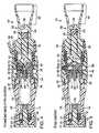
- FIG. 2is a side elevation sectional view of the first embodiment, showing the injector as it would be shipped or stored;
- FIG. 3is a side elevation sectional view of the first embodiment, showing the injector in a ready to prime configuration
- FIG. 3Ais an enlarged, fragmentary side elevation sectional view of the first embodiment as depicted in FIG. 2, showing a priming bushing in a first position with the spherical locking body disposed in a forward, non-locking position;
- FIG. 3Bis an enlarged, fragmentary side elevation sectional view of the first embodiment as shown in FIG. 3, showing the priming bushing in a second position and the locking body disposed in a rearward, locking position;
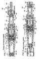
- FIG. 4is a side elevation sectional view of the first embodiment, showing the unit primed and ready to actuate;
- FIG. 5is a side elevation sectional view of the first embodiment, showing the unit after it has been actuated;
- FIG. 6is an exploded view of a second embodiment of the present invention that may be used for subcutaneous injections
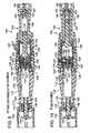
- FIG. 7is a side elevation sectional view of the second embodiment, showing the unit as it would be shipped or stored;
- FIG. 8is a side elevation sectional view of the second embodiment, showing the unit in a ready to prime configuration
- FIG. 9is a side elevation sectional view of the second embodiment, showing the unit primed and ready to actuate;
- FIG. 10is a side elevation sectional view of the second embodiment, showing the unit after it has been actuated.
- FIGS. 1-5depict a first embodiment of a needle-free injection system, or injector 10 , according to the present invention that may be employed for performing intradermal injections.
- FIGS. 6-10depict a second embodiment of a needle-free injector 100 according to the present invention that may be employed for performing subcutaneous or intramuscular injections. While these embodiments will be individually discussed as this description continues, it is noted that various aspects of each embodiment may be implemented in intradermal, subcutaneous, or intramuscular injection systems, and the invention is not limited to the particular embodiments shown. Components included in these preferred embodiments are discussed below, while typical operation of these embodiments is discussed in the latter sections of this disclosure.
- Injector 10includes injection end 11 and a priming end 13 .
- Injector 10also includes a cap 12 , which initially is positioned at the injector end 11 .
- a push-rodis associated with cap 12 , and for this particular embodiment, the push-rod takes the form of threaded member 14 , though the invention is not so limited. Alternatively, such a push rod may be unthreaded, may include ratchet grooves or may employ any other number of any surface configurations.
- an injection orifice seal 16may be inserted in a distal end of threaded member 14 .
- Cap 12has multiple purposes, which will be discussed further below. Briefly, however, cap 12 may be employed during shipping and/or storage of injector 10 to seal injector 10 and prevent contamination. Cap 12 may also be employed to prime injector 10 , as will be discussed below.
- injector 10may further include a priming bushing 18 and a bushing locking body 20 .
- locking body 20is in the form of a spherical ball.
- Bushing 18 and locking body 20may cooperate with threaded member 14 when priming injector. Priming of injector 10 will be discussed in further detail below. Briefly, however, FIG. 1A depicts an enlarged isometric view of bushing 18 .
- Bushing 18includes a first cylindrical portion 63 and a second cylindrical portion 64 .
- Channel 21is formed in both cylindrical portions, with portion 64 being larger in diameter than portion 63 .
- Locking body 20is shown disposed within the portion of channel 21 formed as part of cylindrical portion 63 . As may be seen, approximately fifty percent of locking body 20 extends above channel 19 . When locking body 20 is disposed within the portion of channel 21 formed in portion 64 , locking body 20 would typically not extend above channel 21 .
- FIG. 1Bdepicts a sectional view of housing along line 1 B— 1 B in FIG. 1 .
- housing 28includes an inner wall 65 and an outer wall 66 . These walls have circumferences that correspond, respectively, with portions 63 and 64 of bushing 18 , and are adapted to receive bushing 18 .
- Slot 68is formed in inner wall 65 of housing 28 , and may cooperate with slot 21 of bushing 18 in fixing bushing 18 with housing 28 during priming.
- injector 10may also include a gas cylinder 22 , a gas seal 24 , both of which may be inserted into sleeve 26 and work cooperatively in providing pressurized gas for performing injections with injector 10 .
- sleeve 26may precisely position gas cartridge 22 and gas seal 24 with respect to the other components of injector 10 to facilitate priming and actuation of the injector.
- bushing 18 , locking body 20 , gas cylinder 22 , gas seal 24 and sleeve 26may be inserted into a housing 28 when assembling injector 10 .
- Housing 28may receive a slidable trigger plate 30 , which may be used to actuate injector 10 after priming, as will be discussed below.
- trigger plate 30includes tab 32 that may prevent inadvertent actuation of injector 10 until desired for injection of a user.
- trigger plate 30may include corrugations 34 to facilitate sliding of trigger plate 30 when actuating injector 10 .
- a second trigger plate 36may also be included.
- trigger plates 30 and 36may include a recess 38 , which is adapted to at least partially receive gas channel seal 39 as a result of actuation of injector 10 , as will be discussed in further detail hereafter.
- Trigger plates 30 and 36may also include a locking tab 40 and a locking tab receiving structure 42 , which may used to couple trigger plate 30 with trigger plate 36 on opposing sides of housing 28 , as is indicated in FIG. 1 . In such a configuration, trigger plates 30 and 36 would typically move in unison when slid axially to actuate injector 10 .
- Injector 10may also include a piercing member 44 , and a gas delivery assembly 46 , both of which may be received by housing 28 .
- piercing member 44may take the form of a hollow needle, though other techniques may exist.
- Piercing member 44typically pierces gas cylinder 22 to release pressurized gas, which may then be employed to facilitate injection of a patient by actuating injector 10 via trigger plate 30 and/or 36 .
- a cupped portion 47 of gas delivery assembly 46may be disposed around piercing member 44 . Cupped portion 47 may be flexible so as to expand when pressurized gas is released from gas cylinder 22 when pierced by piercing member 44 .
- cupped portion 47may facilitate sealing the pressurized gas within injector 10 until actuation.
- Gas channel seal 39is typically inserted into gas delivery assembly 46 via opening 48 (see FIG. 1 ). Additional specifics of this assembly are discussed below. Cupped portion 47 and gas channel seal 39 , co-operate to form a gas sealing system 49 , which prevents actuation of injector 10 prior to trigger plate 30 being moved to the “fire” position
- a plunger 50including a flanged end 52 and plug 54 , may also be included in injector 10 .
- Gas delivery assembly 46may receive flanged end 52 , as is indicated in FIG. 1 .
- Plunger 50 and plug 54may be received by nozzle 56 , typically via injectate storage chamber 58 .
- plug 54typically cooperates with plunger 50 to eject injectate from storage chamber 58 via injection orifice 60 as a result of actuating injector 10 .
- nozzle 56includes a spacer 62 , which makes injector 10 particularly suitable for performing intradermal injections. It is noted that the majority of components of injector 10 (and 100 ) would typically be fabricated with molded plastic, though the invention is not so limited.
- Injector 100includes a cap 102 , which has threaded member 104 incorporated on a first side.
- An injection orifice seal 106may be disposed on an opposite side of cap 102 from threaded member 104 .
- threaded member 14may operate as a push rod when priming injector 100 and take any number or forms.
- cap 102may be employed during shipping and/or storage of injector 100 to seal the system and prevent contamination. Cap 102 may also be employed to prime injector 100 , as will be discussed further below.
- injector 100indicated by reference numerals 108 - 138 correspond with, and are substantially the same as the components and features of injector 10 indicated by reference numerals 18 - 48 in FIG. 1 and described above. For the purpose of brevity, these components and features will not be described in detail again with regard to FIG. 6 .
- injector 100differs from injector 10 , illustrated in FIG. 1, in the techniques employed for injectate storage and delivery of injectate into a patient.
- plunger 140contains a flanged end 142 that may be received by gas delivery assembly 136 , in a similar manner as previously discussed.
- Plunger 140 and plug 144for injector 100 , may be received by injectate storage sleeve 146 .
- Storage sleeve 146typically takes the form of a glass cylinder, though the invention is not limited in this respect.
- a seal 148 having a channel 150 formed thereinmay be inserted into a distal end of storage sleeve 146 .
- a valve body 152may be initially disposed with channel 150 prior to priming of the system for injection of a patient.
- nozzle 156when assembling injector 100 .
- nozzle 156includes injection orifice 158 , which is formed therein. Additional aspects of the structure and operation of nozzle 156 are discussed below.
- injector 10is shown as it may be stored or shipped.
- cap 12is engaged with spacer 62 .
- injection orifice seal 16is in physical abutment with injection orifice 60 , which may prevent contamination of an injectate disposed within storage chamber 58 as well as loss of the injectate via injection orifice 60 .
- injector 10is in what may be termed, an unprimed state.
- sleeve 26in which gas cartridge 22 is disposed, and gas delivery assembly 46 , are rearwardly disposed within housing 28 and gas cartridge 22 is not yet pierced.
- injector 10is shown in a ready to prime condition.
- threaded member 14 of cap 12has been threaded into threaded bore 19 of priming bushing 18
- injection orifice seal 16is in abutment with gas cartridge 22 .
- frictional forces resulting from the interface between gas cartridge sleeve 26 , gas delivery assembly 46 and housing 28may result in bushing 18 spinning within housing 28 , preventing further advance of threaded member 14 through threaded bore 19 .
- locking body 20may be allowed to move into the rearward position as a result of gravitational forces acting on locking body 20 .
- FIGS. 3A and 3Bdepict more detailed, fragmentary sectional views of housing 28 , bushing 18 and locking body 20 , and illustrate the movement of locking body 20 from the forward to the rearward position.
- FIG. 3Adepicts locking body 20 in the forward position, as shown in FIG. 2 .
- slot 21 of bushing 18is not aligned with slot 68 of housing 28 .
- FIG. 3Bcorresponds with FIG. 3A, and depicts bushing 18 rotated from the depiction of FIG. 3A such that slot 21 of bushing 18 is aligned with slot 68 of housing 28 .
- locking body 20is now disposed in a rearward position within slot 21 in bushing 18 and slot 68 in housing 28 .
- further rotation of cap 12will result in locking body 20 engaging both bushing 18 and housing 28 via respective slots 21 and 68 , and positionally fixing bushing 18 with respect to housing 28 .
- Fixing bushing 18 within housing 28will then allow threaded member 14 to continue advancing into threaded bore 19 , urging gas cartridge 22 , gas seal 24 and sleeve 26 forward within housing 28 .
- This forward movementwill, in turn, result in forward movement of piercing member 44 , gas delivery assembly 46 , plunger 50 and plug 54 , which will typically result in displacing any air within storage chamber 58 , along with a small amount of injectate, effecting priming of injector 10 .
- gas seal 24is positioned properly against gas cartridge 22 as a result of initially being precisely positioned by chamfered portions of sleeve 26 .
- This forward movement, resulting from advancing threaded member 14 into injector 10changes the condition of injector 10 from that shown in FIG. 3 to the condition shown in FIG. 4 .
- injector 10is shown in a primed and ready to fire condition.
- cap 12is threaded completely into threaded bore 19 in bushing 18 .
- Gas cartridge 22has been pierced by piercing member 44 , allowing pressurized gas to enter a radial gas channel portion 70 within gas delivery assembly 46 .
- cupped portion 47 of sealing system 49may expand and thus prevent the pressurized gas from escaping the injector.
- the pressurized gaswill also exert pressure on gas channel seal 39 . Comparing the relative position of gas channel seal 39 in FIGS.
- gas channel seal 39is moved from a partially rearward position with respective to recess 38 in trigger plate 30 to a position forward of recess 38 .
- pressurized gas released from gas cartridge 22once pierced by piercing member 44 , will result in gas channel seal 39 being urged upwardly against the underside of trigger plate 30 .
- pressurized gasis typically retained within injector 10 , as it cannot flow into axial gas channel portion 72 or exit gas delivery assembly 46 via opening 48 due to gas channel seal 39 being disposed between radial gas channel portion 70 , axial gas channel portion 72 and trigger plate 30 .
- injector 10is primed and ready to be actuated for injection after removal of tab 32 , which will allow trigger plate 30 to be slid forwardly.
- injector 10is shown after actuation.
- Sliding trigger plate 30 forwardresults in gas channel seal 39 being urged upward and being received by recess 38 in trigger plate 30 .
- This displacementallows pressurized gas to flow through gas delivery assembly 46 via radial gas channel portion 70 and axial gas channel portion 72 , and impinge on flanged end 52 of plunger 50 .
- plunger 50 and plug 54may be urged rapidly forward, causing an injectate disposed within storage chamber 58 to be expelled via injection orifice 60 to effect injection of a patient.
- spacer 62makes injector 10 particularly suitable for performing intradermal injections.
- injectate expelled from storage chamber 58 in this mannermay be used for such intradermal injections.
- injector 100The operation of injector 100 , described above with reference to FIG. 6, will now be described while referring to FIGS. 7-10 which show injector 100 , respectively, in a storage and shipping condition; a ready to prime condition; a primed and ready to fire condition; and a fired condition.
- FIGS. 7-10show injector 100 , respectively, in a storage and shipping condition; a ready to prime condition; a primed and ready to fire condition; and a fired condition.
- FIGS. 7-10show injector 100 , respectively, in a storage and shipping condition; a ready to prime condition; a primed and ready to fire condition; and a fired condition.
- FIG. 7shows injector 100 in the storage condition.
- injection orifice seal 106is disposed on one side of cap 102 and threaded member 104 is disposed on the opposite side. Because injector 100 is adapted for subcutaneous injections, disposing injection orifice seal 106 on an opposite side of cap 102 from threaded member 104 results in cap 102 being capable of similar functionality as cap 12 of injector 10 , such as preventing contamination and facilitating priming. While injector 100 has been described herein as being suitable for subcutaneous injections, it should be understood that it may be possible to adapt the unit for intramuscular injections as well, simply by increasing the size of injection orifice 158 .
- FIG. 8shows injector 100 in a ready to prime condition
- FIG. 9shows injector 100 in a primed and ready to fire condition. Because threaded member 104 , bushing 108 and locking body 110 function in a substantially similar manner as discussed with respect to FIGS. 1-5, the operation of these components will not be discussed with respect to injector 100 .
- a small amount of injectatemay dribble out of injection orifice 158 , but this is desired to ensure that air has been removed from storage cylinder 146 and injection chamber 164 prior to the injector being used to inject a patient.
- employing bushing 108 and locking body 110may assist in removing air from injector 100 as priming is typically accomplished with injector 100 in a position where the injection is raised with respect to the priming end when such a technique is used. Such an orientation would result in air within storage 146 and injection chamber 164 to rise towards injection orifice 158 , allowing for its expulsion from injector 100 .
- FIG. 10shows injector 100 with tabs 122 removed in a fired condition, after actuation.
- actuation of injector 100may be initiated by sliding trigger plate 120 and/or 126 forward. Pressurized gas from gas cylinder 112 may then displace gas channel seal 129 into recess 128 of trigger plate 120 , allowing the pressurized gas to flow though gas delivery assembly 136 via radial gas channel portion 160 and axial gas channel portion 162 , and then impinge on flanged end 142 of plunger 140 . This impingement may drive plunger 140 and, in turn, plug 144 rapidly forward. This forward movement may then force injectate within storage cylinder 146 to flow around valve 152 , through bypass conduits (not shown) and out injection orifice 158 for subcutaneous injection into a patient.
- Embodiments of the current inventionthus provide apparatus for effective and simple injection, which may be performed by a patient, or other person, using a single hand. This is accomplished using far fewer parts than prior systems. Because this results in the apparatus being relatively inexpensive as compared to prior systems, it may be designed for single use and to be discarded after a single injection.
Landscapes
- Health & Medical Sciences (AREA)
- Vascular Medicine (AREA)
- Engineering & Computer Science (AREA)
- Anesthesiology (AREA)
- Biomedical Technology (AREA)
- Heart & Thoracic Surgery (AREA)
- Hematology (AREA)
- Life Sciences & Earth Sciences (AREA)
- Animal Behavior & Ethology (AREA)
- General Health & Medical Sciences (AREA)
- Public Health (AREA)
- Veterinary Medicine (AREA)
- Infusion, Injection, And Reservoir Apparatuses (AREA)
- Electronic Switches (AREA)
- Treatment Of Water By Ion Exchange (AREA)
- Electrical Discharge Machining, Electrochemical Machining, And Combined Machining (AREA)
Abstract
Description
Claims (39)
Priority Applications (6)
| Application Number | Priority Date | Filing Date | Title |
|---|---|---|---|
| US10/008,563US6607510B2 (en) | 2001-11-09 | 2001-11-09 | Disposable needle-free injection apparatus and method |
| AT02789524TATE359095T1 (en) | 2001-11-09 | 2002-11-08 | NEEDLELESS DISPOSABLE INJECTION DEVICE |
| DE60219505TDE60219505D1 (en) | 2001-11-09 | 2002-11-08 | NEEDLESS ONE-WAY INJECTION DEVICE |
| AU2002352565AAU2002352565A1 (en) | 2001-11-09 | 2002-11-08 | Disposable needle-free injection apparatus and method |
| EP02789524AEP1443985B1 (en) | 2001-11-09 | 2002-11-08 | Disposable needle-free injection apparatus |
| PCT/US2002/035897WO2003041762A2 (en) | 2001-11-09 | 2002-11-08 | Disposable needle-free injection apparatus and method |
Applications Claiming Priority (1)
| Application Number | Priority Date | Filing Date | Title |
|---|---|---|---|
| US10/008,563US6607510B2 (en) | 2001-11-09 | 2001-11-09 | Disposable needle-free injection apparatus and method |
Publications (2)
| Publication Number | Publication Date |
|---|---|
| US20030093030A1 US20030093030A1 (en) | 2003-05-15 |
| US6607510B2true US6607510B2 (en) | 2003-08-19 |
Family
ID=21732313
Family Applications (1)
| Application Number | Title | Priority Date | Filing Date |
|---|---|---|---|
| US10/008,563Expired - Fee RelatedUS6607510B2 (en) | 2001-11-09 | 2001-11-09 | Disposable needle-free injection apparatus and method |
Country Status (6)
| Country | Link |
|---|---|
| US (1) | US6607510B2 (en) |
| EP (1) | EP1443985B1 (en) |
| AT (1) | ATE359095T1 (en) |
| AU (1) | AU2002352565A1 (en) |
| DE (1) | DE60219505D1 (en) |
| WO (1) | WO2003041762A2 (en) |
Cited By (52)
| Publication number | Priority date | Publication date | Assignee | Title |
|---|---|---|---|---|
| US20040111054A1 (en)* | 2002-06-04 | 2004-06-10 | Sergio Landau | High workload needle-free injection system |
| US20040159364A1 (en)* | 2003-02-19 | 2004-08-19 | Bioject Inc. | Needle-free injection system |
| US20040199106A1 (en)* | 2002-06-04 | 2004-10-07 | Sergio Landau | Needle-free injection system |
| US20060129125A1 (en)* | 2004-12-09 | 2006-06-15 | Ams Research Corporation | Needleless delivery systems |
| US20080071211A1 (en)* | 2006-09-19 | 2008-03-20 | Bioject Inc. | Needle-free injector and process for providing serial injections |
| WO2008045161A2 (en) | 2006-10-06 | 2008-04-17 | Bioject Inc. | Triggering mechanism for needle-free injector |
| US20080119823A1 (en)* | 2006-11-21 | 2008-05-22 | Crank Justin M | Injection Tube for Jet Injection Device |
| US20080171968A1 (en)* | 2007-01-15 | 2008-07-17 | Bioject, Inc. | Methods of administering injectables to a joint with a needle-free injection system |
| WO2008103997A3 (en)* | 2007-02-23 | 2008-10-23 | Bioject Inc | Needle-free injection devices and drug delivery systems therefor |
| US20090005735A1 (en)* | 2006-03-03 | 2009-01-01 | Shl Group Ab | Medical Device with Orientation Sensitive Priming Mechanism |
| US20090312696A1 (en)* | 2005-12-28 | 2009-12-17 | Copa Vincent G | Devices, Systems, and Related Methods for Delivery of Fluid to Tissue |
| US20100025503A1 (en)* | 2007-11-26 | 2010-02-04 | Bioject Inc. | Needle-free injection device with nozzle auto-disable |
| US20100069846A1 (en)* | 2004-01-23 | 2010-03-18 | The Medical House Plc | Injection device |
| US20100076374A1 (en)* | 2007-11-26 | 2010-03-25 | Bioject Inc. | Injection device plunger auto-disable |
| US20100130930A1 (en)* | 2007-03-07 | 2010-05-27 | The Medical House Plc | autoinjector |
| US7785292B2 (en) | 2004-05-28 | 2010-08-31 | Ethicon Endo-Surgery, Inc. | Injection device |
| US7901377B1 (en) | 2004-05-28 | 2011-03-08 | Cilag Gmbh International | Injection device |
| US8277414B2 (en) | 2004-05-28 | 2012-10-02 | Cilag Gmbh International | Injection device |
| USRE43824E1 (en) | 2001-01-11 | 2012-11-20 | Powder Pharmaceuticals Inc. | Needleless syringe |
| US8313463B2 (en) | 2004-05-28 | 2012-11-20 | Cilag Gmbh International | Injection device |
| US8313465B2 (en) | 2004-05-28 | 2012-11-20 | Cilag Gmbh International | Injection device |
| US8313464B2 (en) | 2004-05-28 | 2012-11-20 | Cilag Gmbh International | Injection device |
| US8317751B2 (en) | 2005-04-06 | 2012-11-27 | Cilag Gmbh International | Injection device |
| US20120315294A1 (en)* | 2011-06-01 | 2012-12-13 | Sanipa Suradhat | Needle-free administration of PRRSV vaccines |
| US8343110B2 (en) | 2004-05-28 | 2013-01-01 | Cilag Gmbh International | Injection device |
| US8366669B2 (en) | 2005-04-06 | 2013-02-05 | Cilag Gmbh International | Injection device |
| US20130072865A1 (en)* | 2002-03-20 | 2013-03-21 | Gregor John McLennan Anderson | Casing |
| US8540665B2 (en) | 2007-05-04 | 2013-09-24 | Powder Pharmaceuticals Inc. | Particle cassettes and processes therefor |
| US8591457B2 (en) | 2005-08-10 | 2013-11-26 | Alza Corporation | Method for making a needle-free jet injection drug delivery device |
| US8734393B2 (en) | 2009-04-23 | 2014-05-27 | The Medical House Limited | Autoinjector |
| US8747357B2 (en) | 2006-12-18 | 2014-06-10 | The Medical House Limited | Autoinjector |
| US8834419B2 (en) | 2008-06-19 | 2014-09-16 | Cilag Gmbh International | Reusable auto-injector |
| US8845594B2 (en) | 2008-06-19 | 2014-09-30 | Cilag Gmbh International | Auto-injector with filling means |
| US8939958B2 (en) | 2008-06-19 | 2015-01-27 | Cilag Gmbh International | Fluid transfer assembly for a syringe |
| US8968236B2 (en) | 2005-04-06 | 2015-03-03 | Cilag Gmbh International | Injection device |
| US9028451B2 (en) | 2006-06-01 | 2015-05-12 | Cilag Gmbh International | Injection device |
| US9028453B2 (en) | 2008-06-19 | 2015-05-12 | Cilag Gmbh International | Reusable auto-injector |
| US9072833B2 (en) | 2006-06-01 | 2015-07-07 | Cilag Gmbh International | Injection device |
| US9358346B2 (en) | 2005-08-30 | 2016-06-07 | Cilag Gmbh International | Needle assembly for a prefilled syringe system |
| US9649441B2 (en) | 2005-04-06 | 2017-05-16 | Cilag Gmbh International | Injection device (bayonet cap removal) |
| US9675757B2 (en) | 2004-05-28 | 2017-06-13 | Cilag Gmbh International | Injection device |
| US9675758B2 (en) | 2004-05-28 | 2017-06-13 | Cilag Gmbh International | Injection device |
| US9682194B2 (en) | 2008-06-19 | 2017-06-20 | Cilag Gmbh International | Re-useable auto-injector with filling means |
| US9731080B2 (en) | 2005-04-06 | 2017-08-15 | Cilag Gmbh International | Injection device |
| US9757520B2 (en) | 2006-06-01 | 2017-09-12 | Cilag Gmbh International | Injection device |
| US9770558B2 (en) | 2005-09-27 | 2017-09-26 | Cilag Gmbh International | Auto-injection device with needle protecting cap having outer and inner sleeves |
| US9895493B2 (en) | 2004-05-28 | 2018-02-20 | Cilag Gmbh International | Injection device |
| US10709849B2 (en) | 2013-06-11 | 2020-07-14 | Cilag Gmbh International | Guide for an injection device |
| US10799646B2 (en) | 2013-06-11 | 2020-10-13 | Cilag Gmbh International | Injection device |
| US11123492B2 (en) | 2013-06-11 | 2021-09-21 | Cilag Gmbh International | Injection device |
| US11173255B2 (en) | 2013-06-11 | 2021-11-16 | Cilag Gmbh International | Injection device |
| US11642462B2 (en) | 2006-01-23 | 2023-05-09 | Shl Medical Ag | Injection device |
Families Citing this family (8)
| Publication number | Priority date | Publication date | Assignee | Title |
|---|---|---|---|---|
| EP1689465A4 (en)* | 2003-12-05 | 2011-10-12 | Zogenix Inc | A device for readying a needle free injector for delivery |
| GB2410190A (en)* | 2004-01-26 | 2005-07-27 | Medical House Plc | Disposable gas-powered needle-free injection device |
| US20050233287A1 (en)* | 2004-04-14 | 2005-10-20 | Vladimir Bulatov | Accessible computer system |
| US7717874B2 (en)* | 2004-05-28 | 2010-05-18 | Bioject, Inc. | Needle-free injection system |
| EP2532378B1 (en)* | 2004-12-01 | 2016-04-27 | AcuShot, Inc. | Needle-free injector |
| GB0601309D0 (en)* | 2006-01-23 | 2006-03-01 | Medical House The Plc | Injection device |
| WO2013086612A1 (en) | 2011-12-15 | 2013-06-20 | Socpra Sciences Et Genie S.E.C. | Mechanism for puncturing a gas cartridge |
| GB2536421A (en)* | 2015-03-11 | 2016-09-21 | Linde Ag | A device for atomising a liquid |
Citations (36)
| Publication number | Priority date | Publication date | Assignee | Title |
|---|---|---|---|---|
| US2545017A (en) | 1947-06-02 | 1951-03-13 | Gordon D Billingsley | Hypodermic syringe |
| US2653602A (en) | 1950-06-17 | 1953-09-29 | Becton Dickinson Co | Injection device |
| US2667874A (en) | 1951-07-09 | 1954-02-02 | Becton Dickinson Co | Medicament cartridge assembly |
| US2680439A (en) | 1948-09-08 | 1954-06-08 | Arnold K Sutermeister | High-pressure injection device |
| US3110309A (en) | 1960-08-15 | 1963-11-12 | Brunswick Corp | Plastic cartridge needle assembly |
| US3115133A (en) | 1962-05-15 | 1963-12-24 | Morando Emilio Donald | Needleless prefilled disposable hypodermic injector |
| US3292621A (en) | 1963-07-19 | 1966-12-20 | Oscar H Banker | Jet type protable inoculator |
| US3561443A (en) | 1968-09-06 | 1971-02-09 | Oscar H Banker | Inoculator gun with delayed action |
| US3688765A (en) | 1969-10-03 | 1972-09-05 | Jack S Gasaway | Hypodermic injection device |
| US3695266A (en) | 1970-06-18 | 1972-10-03 | Maurice G Lussier | Needleless sequential dosing syringe |
| US3714943A (en) | 1970-12-01 | 1973-02-06 | H Yanof | Medicament injectors |
| US3853125A (en) | 1971-10-05 | 1974-12-10 | W Clark | Disposable needleless injector |
| US3945379A (en) | 1974-08-08 | 1976-03-23 | Smithkline Corporation | Injection device |
| US4059107A (en) | 1975-05-08 | 1977-11-22 | Asahi Kasei Kogyo Kabushiki Kaisha | Two step type pressurized injector |
| US4124024A (en) | 1977-03-03 | 1978-11-07 | Schwebel Paul R | Disposable hypodermic injection ampule |
| US4596556A (en) | 1985-03-25 | 1986-06-24 | Bioject, Inc. | Hypodermic injection apparatus |
| US4680027A (en) | 1985-12-12 | 1987-07-14 | Injet Medical Products, Inc. | Needleless hypodermic injection device |
| US4717384A (en) | 1987-01-15 | 1988-01-05 | Pneu Dart Inc. | Pneumatic hypodermic syringe pole |
| US4790824A (en) | 1987-06-19 | 1988-12-13 | Bioject, Inc. | Non-invasive hypodermic injection device |
| US4913699A (en) | 1988-03-14 | 1990-04-03 | Parsons James S | Disposable needleless injection system |
| US4940460A (en) | 1987-06-19 | 1990-07-10 | Bioject, Inc. | Patient-fillable and non-invasive hypodermic injection device assembly |
| US5009637A (en) | 1987-11-16 | 1991-04-23 | Sy-Quest International Limited | Apparatus for hypodermic injection of liquids |
| US5024656A (en) | 1988-08-30 | 1991-06-18 | Injet Medical Products, Inc. | Gas-pressure-regulated needleless injection system |
| US5383851A (en) | 1992-07-24 | 1995-01-24 | Bioject Inc. | Needleless hypodermic injection device |
| US5503627A (en) | 1989-11-09 | 1996-04-02 | Bioject, Inc. | Ampule for needleless injection |
| US5730723A (en) | 1995-10-10 | 1998-03-24 | Visionary Medical Products Corporation, Inc. | Gas pressured needle-less injection device and method |
| WO1998052632A1 (en) | 1997-05-19 | 1998-11-26 | Bioject, Inc. | Injection apparatus |
| US5891085A (en)* | 1995-01-09 | 1999-04-06 | Medi-Ject Corporation | Nozzle assembly with lost motion connection for medical injector assembly |
| WO2000033899A1 (en) | 1998-12-08 | 2000-06-15 | Bioject, Inc. | Needleless syringe with prefilled cartridge |
| US6096002A (en) | 1998-11-18 | 2000-08-01 | Bioject, Inc. | NGAS powered self-resetting needle-less hypodermic jet injection apparatus and method |
| WO2000048654A1 (en) | 1999-02-18 | 2000-08-24 | Bioject, Inc. | Single-use needle-less hypodermic jet injection apparatus and method |
| WO2001013975A2 (en) | 1999-08-20 | 2001-03-01 | Bioject, Inc. | Dna-based intramuscular injection system for humans |
| WO2001013977A1 (en) | 1999-08-20 | 2001-03-01 | Bioject, Inc. | Intradermal injection system for injecting dna-based injectables into humans |
| US6210359B1 (en) | 2000-01-21 | 2001-04-03 | Jet Medica, L.L.C. | Needleless syringe |
| US6224567B1 (en) | 1999-09-08 | 2001-05-01 | Cambridge Biostability Limited | Modified disposable injector device |
| WO2001074425A1 (en) | 1998-12-08 | 2001-10-11 | Bioject Medical Technologies Inc. | Needleless syringe with prefilled cartridge |
Family Cites Families (3)
| Publication number | Priority date | Publication date | Assignee | Title |
|---|---|---|---|---|
| US6080130A (en)* | 1998-11-14 | 2000-06-27 | Castellano; Thomas P. | Gas power source for a needle-less injector |
| EP0888790A1 (en)* | 1997-07-04 | 1999-01-07 | PowderJect Research Limited | Drug particle delivery device |
| CA2331030A1 (en)* | 2000-02-16 | 2001-08-16 | Roche Diagnostics Gmbh | Hypodermic needleless injection system |
- 2001
- 2001-11-09USUS10/008,563patent/US6607510B2/ennot_activeExpired - Fee Related
- 2002
- 2002-11-08AUAU2002352565Apatent/AU2002352565A1/ennot_activeAbandoned
- 2002-11-08WOPCT/US2002/035897patent/WO2003041762A2/enactiveIP Right Grant
- 2002-11-08ATAT02789524Tpatent/ATE359095T1/ennot_activeIP Right Cessation
- 2002-11-08EPEP02789524Apatent/EP1443985B1/ennot_activeExpired - Lifetime
- 2002-11-08DEDE60219505Tpatent/DE60219505D1/ennot_activeExpired - Lifetime
Patent Citations (39)
| Publication number | Priority date | Publication date | Assignee | Title |
|---|---|---|---|---|
| US2545017A (en) | 1947-06-02 | 1951-03-13 | Gordon D Billingsley | Hypodermic syringe |
| US2680439A (en) | 1948-09-08 | 1954-06-08 | Arnold K Sutermeister | High-pressure injection device |
| US2653602A (en) | 1950-06-17 | 1953-09-29 | Becton Dickinson Co | Injection device |
| US2667874A (en) | 1951-07-09 | 1954-02-02 | Becton Dickinson Co | Medicament cartridge assembly |
| US3110309A (en) | 1960-08-15 | 1963-11-12 | Brunswick Corp | Plastic cartridge needle assembly |
| US3115133A (en) | 1962-05-15 | 1963-12-24 | Morando Emilio Donald | Needleless prefilled disposable hypodermic injector |
| US3292621A (en) | 1963-07-19 | 1966-12-20 | Oscar H Banker | Jet type protable inoculator |
| US3561443A (en) | 1968-09-06 | 1971-02-09 | Oscar H Banker | Inoculator gun with delayed action |
| US3688765A (en) | 1969-10-03 | 1972-09-05 | Jack S Gasaway | Hypodermic injection device |
| US3695266A (en) | 1970-06-18 | 1972-10-03 | Maurice G Lussier | Needleless sequential dosing syringe |
| US3714943A (en) | 1970-12-01 | 1973-02-06 | H Yanof | Medicament injectors |
| US3853125A (en) | 1971-10-05 | 1974-12-10 | W Clark | Disposable needleless injector |
| US3945379A (en) | 1974-08-08 | 1976-03-23 | Smithkline Corporation | Injection device |
| US4059107A (en) | 1975-05-08 | 1977-11-22 | Asahi Kasei Kogyo Kabushiki Kaisha | Two step type pressurized injector |
| US4124024A (en) | 1977-03-03 | 1978-11-07 | Schwebel Paul R | Disposable hypodermic injection ampule |
| US4596556A (en) | 1985-03-25 | 1986-06-24 | Bioject, Inc. | Hypodermic injection apparatus |
| US4680027A (en) | 1985-12-12 | 1987-07-14 | Injet Medical Products, Inc. | Needleless hypodermic injection device |
| US4717384A (en) | 1987-01-15 | 1988-01-05 | Pneu Dart Inc. | Pneumatic hypodermic syringe pole |
| US4790824A (en) | 1987-06-19 | 1988-12-13 | Bioject, Inc. | Non-invasive hypodermic injection device |
| US4940460A (en) | 1987-06-19 | 1990-07-10 | Bioject, Inc. | Patient-fillable and non-invasive hypodermic injection device assembly |
| US5009637A (en) | 1987-11-16 | 1991-04-23 | Sy-Quest International Limited | Apparatus for hypodermic injection of liquids |
| US4913699A (en) | 1988-03-14 | 1990-04-03 | Parsons James S | Disposable needleless injection system |
| US5024656A (en) | 1988-08-30 | 1991-06-18 | Injet Medical Products, Inc. | Gas-pressure-regulated needleless injection system |
| US5503627A (en) | 1989-11-09 | 1996-04-02 | Bioject, Inc. | Ampule for needleless injection |
| US5383851A (en) | 1992-07-24 | 1995-01-24 | Bioject Inc. | Needleless hypodermic injection device |
| US5891085A (en)* | 1995-01-09 | 1999-04-06 | Medi-Ject Corporation | Nozzle assembly with lost motion connection for medical injector assembly |
| US5730723A (en) | 1995-10-10 | 1998-03-24 | Visionary Medical Products Corporation, Inc. | Gas pressured needle-less injection device and method |
| WO1998052632A1 (en) | 1997-05-19 | 1998-11-26 | Bioject, Inc. | Injection apparatus |
| US5993412A (en) | 1997-05-19 | 1999-11-30 | Bioject, Inc. | Injection apparatus |
| US6264629B1 (en) | 1998-11-18 | 2001-07-24 | Bioject, Inc. | Single-use needle-less hypodermic jet injection apparatus and method |
| US6096002A (en) | 1998-11-18 | 2000-08-01 | Bioject, Inc. | NGAS powered self-resetting needle-less hypodermic jet injection apparatus and method |
| WO2000033899A1 (en) | 1998-12-08 | 2000-06-15 | Bioject, Inc. | Needleless syringe with prefilled cartridge |
| US6132395A (en) | 1998-12-08 | 2000-10-17 | Bioject, Inc. | Needleless syringe with prefilled cartridge |
| WO2001074425A1 (en) | 1998-12-08 | 2001-10-11 | Bioject Medical Technologies Inc. | Needleless syringe with prefilled cartridge |
| WO2000048654A1 (en) | 1999-02-18 | 2000-08-24 | Bioject, Inc. | Single-use needle-less hypodermic jet injection apparatus and method |
| WO2001013975A2 (en) | 1999-08-20 | 2001-03-01 | Bioject, Inc. | Dna-based intramuscular injection system for humans |
| WO2001013977A1 (en) | 1999-08-20 | 2001-03-01 | Bioject, Inc. | Intradermal injection system for injecting dna-based injectables into humans |
| US6224567B1 (en) | 1999-09-08 | 2001-05-01 | Cambridge Biostability Limited | Modified disposable injector device |
| US6210359B1 (en) | 2000-01-21 | 2001-04-03 | Jet Medica, L.L.C. | Needleless syringe |
Cited By (74)
| Publication number | Priority date | Publication date | Assignee | Title |
|---|---|---|---|---|
| USRE43824E1 (en) | 2001-01-11 | 2012-11-20 | Powder Pharmaceuticals Inc. | Needleless syringe |
| US9259534B2 (en) | 2002-03-20 | 2016-02-16 | Zogenix, Inc. | Casing |
| US20130072865A1 (en)* | 2002-03-20 | 2013-03-21 | Gregor John McLennan Anderson | Casing |
| US8715259B2 (en)* | 2002-03-20 | 2014-05-06 | Zogenix, Inc. | Casing |
| US7238167B2 (en) | 2002-06-04 | 2007-07-03 | Bioject Inc. | Needle-free injection system |
| US20040111054A1 (en)* | 2002-06-04 | 2004-06-10 | Sergio Landau | High workload needle-free injection system |
| US7156823B2 (en) | 2002-06-04 | 2007-01-02 | Bioject Inc. | High workload needle-free injection system |
| US20040199106A1 (en)* | 2002-06-04 | 2004-10-07 | Sergio Landau | Needle-free injection system |
| US6935384B2 (en) | 2003-02-19 | 2005-08-30 | Bioject Inc. | Needle-free injection system |
| US20040159364A1 (en)* | 2003-02-19 | 2004-08-19 | Bioject Inc. | Needle-free injection system |
| US20100069846A1 (en)* | 2004-01-23 | 2010-03-18 | The Medical House Plc | Injection device |
| US8343110B2 (en) | 2004-05-28 | 2013-01-01 | Cilag Gmbh International | Injection device |
| US7785292B2 (en) | 2004-05-28 | 2010-08-31 | Ethicon Endo-Surgery, Inc. | Injection device |
| US8277414B2 (en) | 2004-05-28 | 2012-10-02 | Cilag Gmbh International | Injection device |
| US9675758B2 (en) | 2004-05-28 | 2017-06-13 | Cilag Gmbh International | Injection device |
| US9675757B2 (en) | 2004-05-28 | 2017-06-13 | Cilag Gmbh International | Injection device |
| US8313464B2 (en) | 2004-05-28 | 2012-11-20 | Cilag Gmbh International | Injection device |
| US8313465B2 (en) | 2004-05-28 | 2012-11-20 | Cilag Gmbh International | Injection device |
| US7901377B1 (en) | 2004-05-28 | 2011-03-08 | Cilag Gmbh International | Injection device |
| US9895493B2 (en) | 2004-05-28 | 2018-02-20 | Cilag Gmbh International | Injection device |
| US8313463B2 (en) | 2004-05-28 | 2012-11-20 | Cilag Gmbh International | Injection device |
| US8986244B2 (en) | 2004-12-09 | 2015-03-24 | Ams Research Corporation | Needleless delivery systems |
| US8262605B2 (en) | 2004-12-09 | 2012-09-11 | Ams Research Corporation | Needleless delivery systems |
| US20060129125A1 (en)* | 2004-12-09 | 2006-06-15 | Ams Research Corporation | Needleless delivery systems |
| US8808232B2 (en) | 2004-12-09 | 2014-08-19 | Ams Research Corporation | Needleless delivery systems |
| US9731080B2 (en) | 2005-04-06 | 2017-08-15 | Cilag Gmbh International | Injection device |
| US8317751B2 (en) | 2005-04-06 | 2012-11-27 | Cilag Gmbh International | Injection device |
| US8968236B2 (en) | 2005-04-06 | 2015-03-03 | Cilag Gmbh International | Injection device |
| US9649441B2 (en) | 2005-04-06 | 2017-05-16 | Cilag Gmbh International | Injection device (bayonet cap removal) |
| US8366669B2 (en) | 2005-04-06 | 2013-02-05 | Cilag Gmbh International | Injection device |
| US8998881B2 (en) | 2005-08-10 | 2015-04-07 | Alza Corporation | Method for delivering drugs to tissue under microjet propulsion |
| US8591457B2 (en) | 2005-08-10 | 2013-11-26 | Alza Corporation | Method for making a needle-free jet injection drug delivery device |
| US9358346B2 (en) | 2005-08-30 | 2016-06-07 | Cilag Gmbh International | Needle assembly for a prefilled syringe system |
| US9770558B2 (en) | 2005-09-27 | 2017-09-26 | Cilag Gmbh International | Auto-injection device with needle protecting cap having outer and inner sleeves |
| US20090312696A1 (en)* | 2005-12-28 | 2009-12-17 | Copa Vincent G | Devices, Systems, and Related Methods for Delivery of Fluid to Tissue |
| US11642462B2 (en) | 2006-01-23 | 2023-05-09 | Shl Medical Ag | Injection device |
| US20090005735A1 (en)* | 2006-03-03 | 2009-01-01 | Shl Group Ab | Medical Device with Orientation Sensitive Priming Mechanism |
| US9757520B2 (en) | 2006-06-01 | 2017-09-12 | Cilag Gmbh International | Injection device |
| US9028451B2 (en) | 2006-06-01 | 2015-05-12 | Cilag Gmbh International | Injection device |
| US9072833B2 (en) | 2006-06-01 | 2015-07-07 | Cilag Gmbh International | Injection device |
| US7942845B2 (en) | 2006-09-19 | 2011-05-17 | Bioject, Inc. | Needle-free injector and process for providing serial injections |
| US20080071211A1 (en)* | 2006-09-19 | 2008-03-20 | Bioject Inc. | Needle-free injector and process for providing serial injections |
| US7547293B2 (en) | 2006-10-06 | 2009-06-16 | Bioject, Inc. | Triggering mechanism for needle-free injector |
| US8105272B2 (en) | 2006-10-06 | 2012-01-31 | Bioject, Inc. | Triggering mechanism for a needle-free injector |
| US20090247940A1 (en)* | 2006-10-06 | 2009-10-01 | Bioject, Inc. | Triggering mechanism for a needle-free injector |
| WO2008045161A2 (en) | 2006-10-06 | 2008-04-17 | Bioject Inc. | Triggering mechanism for needle-free injector |
| US20090259213A1 (en)* | 2006-11-21 | 2009-10-15 | Crank Justin M | Injection tube for jet injection device |
| US9814837B2 (en) | 2006-11-21 | 2017-11-14 | Astora Women's Health Holdings, Llc | Injection tube for jet injection device |
| US20080119823A1 (en)* | 2006-11-21 | 2008-05-22 | Crank Justin M | Injection Tube for Jet Injection Device |
| US8747357B2 (en) | 2006-12-18 | 2014-06-10 | The Medical House Limited | Autoinjector |
| US20080171968A1 (en)* | 2007-01-15 | 2008-07-17 | Bioject, Inc. | Methods of administering injectables to a joint with a needle-free injection system |
| WO2008103997A3 (en)* | 2007-02-23 | 2008-10-23 | Bioject Inc | Needle-free injection devices and drug delivery systems therefor |
| US7744563B2 (en) | 2007-02-23 | 2010-06-29 | Bioject, Inc. | Needle-free injection devices and drug delivery systems therefor |
| US8308697B2 (en) | 2007-03-07 | 2012-11-13 | The Medical House Limited | Autoinjector |
| US20100130930A1 (en)* | 2007-03-07 | 2010-05-27 | The Medical House Plc | autoinjector |
| US8187226B2 (en) | 2007-03-07 | 2012-05-29 | The Medical House Limited | Autoinjector |
| US9044546B2 (en) | 2007-05-04 | 2015-06-02 | Powder Pharmaceuticals Incorporated | Particle cassettes and processes therefor |
| US8540665B2 (en) | 2007-05-04 | 2013-09-24 | Powder Pharmaceuticals Inc. | Particle cassettes and processes therefor |
| US9358338B2 (en) | 2007-05-04 | 2016-06-07 | Powder Pharmaceuticals Incorporated | Particle cassettes and processes therefor |
| US8617099B2 (en) | 2007-11-26 | 2013-12-31 | Bioject Inc. | Injection device plunger auto-disable |
| US20100025503A1 (en)* | 2007-11-26 | 2010-02-04 | Bioject Inc. | Needle-free injection device with nozzle auto-disable |
| US20100076374A1 (en)* | 2007-11-26 | 2010-03-25 | Bioject Inc. | Injection device plunger auto-disable |
| US8845594B2 (en) | 2008-06-19 | 2014-09-30 | Cilag Gmbh International | Auto-injector with filling means |
| US9682194B2 (en) | 2008-06-19 | 2017-06-20 | Cilag Gmbh International | Re-useable auto-injector with filling means |
| US8834419B2 (en) | 2008-06-19 | 2014-09-16 | Cilag Gmbh International | Reusable auto-injector |
| US8939958B2 (en) | 2008-06-19 | 2015-01-27 | Cilag Gmbh International | Fluid transfer assembly for a syringe |
| US9028453B2 (en) | 2008-06-19 | 2015-05-12 | Cilag Gmbh International | Reusable auto-injector |
| US8734393B2 (en) | 2009-04-23 | 2014-05-27 | The Medical House Limited | Autoinjector |
| US9669085B2 (en)* | 2011-06-01 | 2017-06-06 | Merial Inc. | Needle-free administration of PRRSV vaccines |
| US20120315294A1 (en)* | 2011-06-01 | 2012-12-13 | Sanipa Suradhat | Needle-free administration of PRRSV vaccines |
| US10709849B2 (en) | 2013-06-11 | 2020-07-14 | Cilag Gmbh International | Guide for an injection device |
| US10799646B2 (en) | 2013-06-11 | 2020-10-13 | Cilag Gmbh International | Injection device |
| US11123492B2 (en) | 2013-06-11 | 2021-09-21 | Cilag Gmbh International | Injection device |
| US11173255B2 (en) | 2013-06-11 | 2021-11-16 | Cilag Gmbh International | Injection device |
Also Published As
| Publication number | Publication date |
|---|---|
| EP1443985A4 (en) | 2005-11-30 |
| EP1443985A2 (en) | 2004-08-11 |
| WO2003041762A2 (en) | 2003-05-22 |
| EP1443985B1 (en) | 2007-04-11 |
| WO2003041762A3 (en) | 2003-11-27 |
| US20030093030A1 (en) | 2003-05-15 |
| AU2002352565A1 (en) | 2003-05-26 |
| ATE359095T1 (en) | 2007-05-15 |
| DE60219505D1 (en) | 2007-05-24 |
Similar Documents
| Publication | Publication Date | Title |
|---|---|---|
| US6607510B2 (en) | Disposable needle-free injection apparatus and method | |
| US6264629B1 (en) | Single-use needle-less hypodermic jet injection apparatus and method | |
| US11602597B2 (en) | Prefilled syringe with breakaway force feature | |
| US6783509B1 (en) | Single-use needle-less hypodermic jet injection apparatus and method | |
| US5643211A (en) | Nozzle assembly having a frangible plunger | |
| CN101132820B (en) | Prefilled needle assisted jet injector | |
| US6689093B2 (en) | Single-use needle-less hypodermic jet injection apparatus and method | |
| US4874367A (en) | Hypodermic jet injector and cartridge therefor | |
| US6123684A (en) | Loading mechanism for medical injector assembly | |
| US5865795A (en) | Safety mechanism for injection devices | |
| EP2185227B1 (en) | Injection devices | |
| JP4299466B2 (en) | Needle-assisted jet injector | |
| US6641554B2 (en) | Disposable needle-free injection apparatus and method | |
| EP1237598B1 (en) | Medical injector and medicament loading system for use therewith | |
| US5073165A (en) | Hypodermic jet injector and cartridge therefor | |
| JP2010279706A (en) | Needle-free injection system | |
| KR20060129024A (en) | Injection device | |
| JP2002065851A (en) | Needle-less injector | |
| US20090292239A1 (en) | Injector System for Needleless, High Pressure Delivery of a Medicament | |
| EP0300694A1 (en) | Non-reusable syringe | |
| EP0956059A1 (en) | Nozzle assembly with adjustable plunger travel gap | |
| WO1997031664A1 (en) | Frangible plunger for nozzle assembly | |
| EP2846870B1 (en) | Device for inserting needles | |
| EP1354608A1 (en) | Jet injector having mechanism for creating air-in-tip |
Legal Events
| Date | Code | Title | Description |
|---|---|---|---|
| AS | Assignment | Owner name:BIOJECT MEDICAL TECHNOLOGIES INC., OREGON Free format text:ASSIGNMENT OF ASSIGNORS INTEREST;ASSIGNOR:LANDAU, SERGIO;REEL/FRAME:012373/0416 Effective date:20011109 | |
| AS | Assignment | Owner name:BIOJECT INC., OREGON Free format text:ASSIGNMENT OF ASSIGNORS INTEREST;ASSIGNOR:BIOJECT MEDICAL TECHNOLOGIES INC.;REEL/FRAME:014601/0079 Effective date:20031014 | |
| AS | Assignment | Owner name:PARTNERS FOR GROWTH, L.P., CALIFORNIA Free format text:SECURITY AGREEMENT;ASSIGNOR:BIOJECT, INC.;REEL/FRAME:015487/0202 Effective date:20041215 | |
| AS | Assignment | Owner name:PARTNERS FOR GROWTH, L.P.,CALIFORNIA Free format text:SECURITY AGREEMENT;ASSIGNOR:BIOJECT, INC.;REEL/FRAME:017379/0255 Effective date:20060329 Owner name:PARTNERS FOR GROWTH, L.P., CALIFORNIA Free format text:SECURITY AGREEMENT;ASSIGNOR:BIOJECT, INC.;REEL/FRAME:017379/0255 Effective date:20060329 | |
| AS | Assignment | Owner name:PARTNERS FOR GROWTH, L.P.,CALIFORNIA Free format text:SECURITY AGREEMENT;ASSIGNOR:BIOJECT, INC.;REEL/FRAME:018606/0671 Effective date:20061211 Owner name:PARTNERS FOR GROWTH, L.P., CALIFORNIA Free format text:SECURITY AGREEMENT;ASSIGNOR:BIOJECT, INC.;REEL/FRAME:018606/0671 Effective date:20061211 | |
| FPAY | Fee payment | Year of fee payment:4 | |
| AS | Assignment | Owner name:PARTNERS FOR GROWTH, L.P., CALIFORNIA Free format text:SECURITY AGREEMENT;ASSIGNOR:BIOJECT, INC.;REEL/FRAME:019773/0642 Effective date:20070831 Owner name:PARTNERS FOR GROWTH, L.P.,CALIFORNIA Free format text:SECURITY AGREEMENT;ASSIGNOR:BIOJECT, INC.;REEL/FRAME:019773/0642 Effective date:20070831 | |
| REMI | Maintenance fee reminder mailed | ||
| FPAY | Fee payment | Year of fee payment:8 | |
| SULP | Surcharge for late payment | Year of fee payment:7 | |
| REMI | Maintenance fee reminder mailed | ||
| LAPS | Lapse for failure to pay maintenance fees | ||
| STCH | Information on status: patent discontinuation | Free format text:PATENT EXPIRED DUE TO NONPAYMENT OF MAINTENANCE FEES UNDER 37 CFR 1.362 | |
| FP | Lapsed due to failure to pay maintenance fee | Effective date:20150819 |