US6607286B2 - Lens and lens cap with sawtooth portion for light emitting diode - Google Patents
Lens and lens cap with sawtooth portion for light emitting diodeDownload PDFInfo
- Publication number
- US6607286B2 US6607286B2US09/849,084US84908401AUS6607286B2US 6607286 B2US6607286 B2US 6607286B2US 84908401 AUS84908401 AUS 84908401AUS 6607286 B2US6607286 B2US 6607286B2
- Authority
- US
- United States
- Prior art keywords
- lens
- central axis
- cap
- light source
- funnel
- Prior art date
- Legal status (The legal status is an assumption and is not a legal conclusion. Google has not performed a legal analysis and makes no representation as to the accuracy of the status listed.)
- Expired - Lifetime
Links
Images


Classifications
- H—ELECTRICITY
- H10—SEMICONDUCTOR DEVICES; ELECTRIC SOLID-STATE DEVICES NOT OTHERWISE PROVIDED FOR
- H10H—INORGANIC LIGHT-EMITTING SEMICONDUCTOR DEVICES HAVING POTENTIAL BARRIERS
- H10H20/00—Individual inorganic light-emitting semiconductor devices having potential barriers, e.g. light-emitting diodes [LED]
- H10H20/80—Constructional details
- H10H20/85—Packages
- H10H20/855—Optical field-shaping means, e.g. lenses
- F—MECHANICAL ENGINEERING; LIGHTING; HEATING; WEAPONS; BLASTING
- F21—LIGHTING
- F21V—FUNCTIONAL FEATURES OR DETAILS OF LIGHTING DEVICES OR SYSTEMS THEREOF; STRUCTURAL COMBINATIONS OF LIGHTING DEVICES WITH OTHER ARTICLES, NOT OTHERWISE PROVIDED FOR
- F21V13/00—Producing particular characteristics or distribution of the light emitted by means of a combination of elements specified in two or more of main groups F21V1/00 - F21V11/00
- F21V13/02—Combinations of only two kinds of elements
- F21V13/04—Combinations of only two kinds of elements the elements being reflectors and refractors
- F—MECHANICAL ENGINEERING; LIGHTING; HEATING; WEAPONS; BLASTING
- F21—LIGHTING
- F21V—FUNCTIONAL FEATURES OR DETAILS OF LIGHTING DEVICES OR SYSTEMS THEREOF; STRUCTURAL COMBINATIONS OF LIGHTING DEVICES WITH OTHER ARTICLES, NOT OTHERWISE PROVIDED FOR
- F21V5/00—Refractors for light sources
- F21V5/04—Refractors for light sources of lens shape
- F—MECHANICAL ENGINEERING; LIGHTING; HEATING; WEAPONS; BLASTING
- F21—LIGHTING
- F21V—FUNCTIONAL FEATURES OR DETAILS OF LIGHTING DEVICES OR SYSTEMS THEREOF; STRUCTURAL COMBINATIONS OF LIGHTING DEVICES WITH OTHER ARTICLES, NOT OTHERWISE PROVIDED FOR
- F21V7/00—Reflectors for light sources
- F21V7/0091—Reflectors for light sources using total internal reflection
- G—PHYSICS
- G02—OPTICS
- G02B—OPTICAL ELEMENTS, SYSTEMS OR APPARATUS
- G02B19/00—Condensers, e.g. light collectors or similar non-imaging optics
- G02B19/0004—Condensers, e.g. light collectors or similar non-imaging optics characterised by the optical means employed
- G02B19/0028—Condensers, e.g. light collectors or similar non-imaging optics characterised by the optical means employed refractive and reflective surfaces, e.g. non-imaging catadioptric systems
- G—PHYSICS
- G02—OPTICS
- G02B—OPTICAL ELEMENTS, SYSTEMS OR APPARATUS
- G02B19/00—Condensers, e.g. light collectors or similar non-imaging optics
- G02B19/0033—Condensers, e.g. light collectors or similar non-imaging optics characterised by the use
- G02B19/0047—Condensers, e.g. light collectors or similar non-imaging optics characterised by the use for use with a light source
- G02B19/0061—Condensers, e.g. light collectors or similar non-imaging optics characterised by the use for use with a light source the light source comprising a LED
- G—PHYSICS
- G02—OPTICS
- G02B—OPTICAL ELEMENTS, SYSTEMS OR APPARATUS
- G02B19/00—Condensers, e.g. light collectors or similar non-imaging optics
- G02B19/0033—Condensers, e.g. light collectors or similar non-imaging optics characterised by the use
- G02B19/0047—Condensers, e.g. light collectors or similar non-imaging optics characterised by the use for use with a light source
- G02B19/0071—Condensers, e.g. light collectors or similar non-imaging optics characterised by the use for use with a light source adapted to illuminate a complete hemisphere or a plane extending 360 degrees around the source
- G—PHYSICS
- G02—OPTICS
- G02B—OPTICAL ELEMENTS, SYSTEMS OR APPARATUS
- G02B3/00—Simple or compound lenses
- G02B3/02—Simple or compound lenses with non-spherical faces
- G02B3/08—Simple or compound lenses with non-spherical faces with discontinuous faces, e.g. Fresnel lens
- F—MECHANICAL ENGINEERING; LIGHTING; HEATING; WEAPONS; BLASTING
- F21—LIGHTING
- F21Y—INDEXING SCHEME ASSOCIATED WITH SUBCLASSES F21K, F21L, F21S and F21V, RELATING TO THE FORM OR THE KIND OF THE LIGHT SOURCES OR OF THE COLOUR OF THE LIGHT EMITTED
- F21Y2115/00—Light-generating elements of semiconductor light sources
- F21Y2115/10—Light-emitting diodes [LED]
- H—ELECTRICITY
- H10—SEMICONDUCTOR DEVICES; ELECTRIC SOLID-STATE DEVICES NOT OTHERWISE PROVIDED FOR
- H10H—INORGANIC LIGHT-EMITTING SEMICONDUCTOR DEVICES HAVING POTENTIAL BARRIERS
- H10H20/00—Individual inorganic light-emitting semiconductor devices having potential barriers, e.g. light-emitting diodes [LED]
- H10H20/80—Constructional details
- H10H20/85—Packages
- H10H20/855—Optical field-shaping means, e.g. lenses
- H10H20/856—Reflecting means
- Y—GENERAL TAGGING OF NEW TECHNOLOGICAL DEVELOPMENTS; GENERAL TAGGING OF CROSS-SECTIONAL TECHNOLOGIES SPANNING OVER SEVERAL SECTIONS OF THE IPC; TECHNICAL SUBJECTS COVERED BY FORMER USPC CROSS-REFERENCE ART COLLECTIONS [XRACs] AND DIGESTS
- Y10—TECHNICAL SUBJECTS COVERED BY FORMER USPC
- Y10S—TECHNICAL SUBJECTS COVERED BY FORMER USPC CROSS-REFERENCE ART COLLECTIONS [XRACs] AND DIGESTS
- Y10S362/00—Illumination
- Y10S362/80—Light emitting diode
Definitions
- This inventionrelates generally to light emitting devices and more particularly to side emitting light emitting diodes (LEDs).
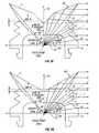
- FIG. 1Aillustrates a conventional LED package 10 .
- LED package 10has a hemispherical lens 12 of a type well-known in the art.
- Package 10may also have a reflector cup (not shown), in which an LED chip (not shown) resides, that reflects light emitted from the bottom and sides of the LED chip toward the observer.
- other types of reflectorsreflect the LED chip's emitted light in a particular direction.
- Lens 12creates a field of illumination 14 roughly along a longitudinal package axis 16 of LED package 10 .
- the vast majority of light emitted from an LED package 10 with a hemispherical lens 12is emitted upwards away from LED package 10 with only a small portion emitted out from the sides of LED package 10 .
- FIG. 1Billustrates a known light emitting diode (LED) package 30 with a longitudinal package axis 26 .
- LED package 30includes an LED chip 38 , a lens 32 with straight vertical sidewall 35 and a funnel-shaped top surface 37 .
- the first light path P 1is desirable with the light emitted from chip 38 and traveling to surface 37 where total internal reflection (TIR) causes the light to exit through sidewall 35 at approximately 90 degrees to the longitudinal axis.
- the second light path P 2is light emitted from chip 38 towards sidewall 35 at an angle causing TIR or a reflection from sidewall 35 causing the light to exit package 30 at an angle not close to perpendicular to the longitudinal axis. This path is not desirable and limits the efficiency of side extracted light.
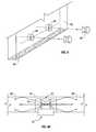
- FIG. 2illustrates the conventional LED package 10 of FIG. 1 coupled along an edge of a portion of a refractive light guide 20 .
- LED package 10is positioned on the edge of light guide 20 along the width of light guide 20 .
- Light rays R 1 , R 2 , R 3 emitted by LED package 10are propagated along the length of light guide 20 .
- FIG. 3illustrates a plurality of conventional LED packages 10 positioned along the width of light guide 20 of FIG. 2 .
- These conventional LED/light guide combinationsare inefficient as they require a large number of LED packages 10 to illuminate the light guide and result in coupling inefficiencies due to relatively small acceptance angles.
- These conventional LED packages 10must be arranged along the entire length of one side of light guide 20 to fully illuminate light guide 20 .
- Light emitting devices with side emission of lightallow light guides and reflectors to have very thin profiles with large illuminated areas.
- a lensin accordance with one embodiment of the invention, includes a body.
- the bodyfurther includes a central axis running along a length of the body and a first surface for coupling to a light source.
- a sawtooth lens portionwhich refracts light emitted from the light source such that a majority of light emitted from the sawtooth lens portion is generally perpendicular to the central axis of the body.
- a funnel-shaped lens portionconnected to the sawtooth lens portion where the funnel-shaped lens portion reflects light emitted from the light source such that a majority of light emitted from the funnel-shaped lens portion is generally perpendicular to the central axis of the body.
- a lens cap attachable to a light sourceincludes a body.
- the bodyfurther includes a central axis running along a length of said body and a first surface for coupling to a light source.
- a sawtooth lens portionwhich refracts light emitted from the light source such that a majority of light emitted from the sawtooth lens portion is generally perpendicular to the central axis of the body.
- a funnel-shaped lens portionis connected to the sawtooth lens portion where the funnel-shaped lens portion reflects light emitted from the light source such that a majority of light emitted from the funnel-shaped lens portion is generally perpendicular to the central axis of the body.
- FIG. 1Aillustrates a conventional LED package.
- FIG. 1Billustrates another conventional LED package.
- FIG. 2illustrates a cross-sectional view of a conventional edge-illuminated light guide.
- FIG. 3illustrates a perspective view of the light guide of FIG. 2 .
- FIG. 4illustrates one embodiment of the invention.
- FIG. 5Aillustrates a cross-sectional view of the LED package of FIG. 4 .
- FIG. 5Billustrates a cross-sectional view of the lens mating to the housing of the LED package base.
- FIG. 5Cillustrates a close-up of the lens/housing mating of FIG. 5 B.
- FIG. 5Dillustrates a cross-sectional view of a lens cap mating to an LED package.
- FIG. 5Eillustrates ray-traces of one embodiment of a lens.
- FIG. 5Fillustrates ray-traces of another embodiment of a lens.
- FIG. 5Gillustrates ray-traces of a further embodiment of a lens.
- FIG. 6illustrates side-emission of light from the LED package of FIG. 4 .
- FIG. 7Aillustrates a cross-sectional view of the side-emission of light from the LED package of FIG. 4 into two light guides.
- FIG. 7Billustrates a cross-sectional view of the side-emission of light from the LED package of FIG. 4 into a light guide.
- FIG. 7Cillustrates a cross-sectional view of the side-emission of light from the LED package of FIG. 4 into a light guide.
- FIG. 7Dillustrates a cross-sectional view of the side-emission of light from the LED package of FIG. 4 into a light guide.
- FIG. 8illustrates a perspective view of a light guide.
- FIG. 9Aillustrates a cross-sectional view of the LED package of FIG. 4 mounted in a blind-hole of a light guide.
- FIG. 9Billustrates a cross-sectional view of the LED package of FIG. 4 mounted in a blind-hole of a light guide.
- FIG. 9Cillustrates a cross-sectional view of the LED package of FIG. 4 mounted in a blind-hole of a light guide.
- FIG. 10illustrates a cross-sectional view of the LED package of FIG. 4 mounted in a through-hole of a light guide.
- FIG. 11illustrates a conventional LED package coupled to a reflector.
- FIG. 12illustrates the LED package of FIG. 4 in combination with a shallow reflector.
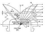
- FIG. 4illustrates an example of a side emitting LED package 40 in accordance with one embodiment of the invention.
- LED package 40includes a longitudinal package axis 43 , an LED package base 42 and a lens 44 .
- Lens 44is coupled to LED package base 42 .
- Longitudinal package axis 43passes through the center of LED package base 43 and lens 44 .
- a surface of LED package base 42supports an LED chip 52 (a semiconductor chip having a light emitting pn junction) for generating light.
- LED chip 52may be one of any number of shapes, including but not limited to a truncated inverted pyramid (TIP) (shown), cube, rectangular solid, or hemisphere.
- TIPtruncated inverted pyramid
- LED chip 52includes a bottom surface that may be in contact with, or coated with, a reflective material. Although LED chip 52 may emit light from all of its sides, base 42 is generally configured to reflect emitted light upwards towards lens 44 along the longitudinal axis of the package. Such packages are conventional and may include a parabolic reflector in which LED chip 52 resides on a surface of package base 42 . One such package is shown in U.S. Pat. No. 4,920,404, assigned to the present assignee and incorporated herein by reference.
- Lens 44may be manufactured as a separate component using a number of well-known techniques such as diamond turning (i.e., the lens is shaped by a lathe with a diamond-bit), injection molding, and casting.
- Lens 44is made of a transparent material, including but not limited to cyclic olefin copolymer (COC), polymethylmethacrolate (PMMA), polycarbonate (PC), PC/PMMA, and polyetherimide (PEI).
- Lens 44includes an index of refraction (n) ranging from between 1.45 to 1.6, preferably 1.53, but could have an index of refraction higher or lower based on the material used.
- lens 44may be formed onto LED package base 42 and LED chip 52 by various techniques including but not limited to injection molding (e.g., insert molding) and casting.
- volume 54there is a volume 54 between lens 44 and LED chip 52 .
- Volume 54may be filled and sealed to prevent contamination of LED 52 using silicone.
- Volume 54may also be in a vacuum state, contain air or some other gas, or filled with an optically transparent resin material, including but not limited to resin, silicone, epoxy, water or any material with an index of refraction in the range of 1.4 to 1.6 may be injected to fill volume 54 .
- the material inside volume 54may be colored to act as a filter in order to allow transmission of all or only a portion of the visible light spectrum. If silicone is used, the silicone may be hard or soft.
- Lens 44may also be colored to act as a filter.
- Lens 44includes a sawtooth, refractive portion 56 and a total internal reflection (TIR) funnel portion 58 .
- the sawtooth portion 56is designed to refract and bend light so that the light exits from lens 44 as close to 90 degrees to the longitudinal package axis 43 as possible.
- the sawteeth or refractive surfaces 59 of the sawtooth portion 56are all light transmissive. Any number of sawteeth 59 may be used within a sawtooth portion of a given length; preferably there is at least one sawtooth.
- Lens 44may be formed as a single piece or, in the alternative, as separate components coupled together.
- Funnel portion 58is designed as a TIR surface.
- the TIR surfacereflects light such that light exits from lens 44 as close to 90 degrees to a longitudinal package axis 43 of LED package 40 as possible. Approximately 33% of the light emitted from LED chip 52 is reflected off the TIR surface of funnel-shaped portion 58 of lens 44 .
- a metallization layere.g., aluminum
- a coating or filme.g., a U.V. inhibitor
- the interface between lens 44 and LED package base 42may also be sealed using any well-known sealant, such as Room Temperature Vulcanizing (RTV) or the like.
- RTVRoom Temperature Vulcanizing
- FIG. 5Billustrates a cross-sectional view of alternative mating of lens 44 to housing 46 of LED package base 42 .
- LED chip 52 and other features of base 42are not shown.
- Lens 44may also be attached to LED package base 42 by various attachment methods, including but not limited to snap-fitting, friction-fitting, heat staking, adhesive bonding, and ultra-sonic welding.
- the features of lens 44as shown in FIG. 5B, are applicable to lenses that are either formed as a separate component or encapsulated onto LED package base 42 .
- FIG. 5Cillustrates a close-up of the lens/housing mating of FIG. 5 B.
- Surface Smay snap fit into surface R.
- Surface Smay friction fit tight with surface R.
- Surface Tmay be welded to surface U using various methods including, without limitation, plastic welding, sonic welding, and linear welding. Sealing or bonding involves several possible combinations, such as surface S and/or T of lens 44 being sealed/bonded to surface R and/or U of housing 46 .
- FIG. 5Dillustrates a cross-sectional view of a lens cap 55 mating to a conventional LED package 10 with a hemispherical lens 12 .
- Lens cap 55may be affixed to lens 12 of LED package 10 by an optical adhesive.
- Lens cap 55includes sawtooth, refractive portion 56 and reflective funnel portion 58 that contain the same and/or similar features that operate in the same and/or similar manner, as described above and below, as refractive and TIR portions 56 , 58 of lens 44 .
- FIGS. 5E, 5 F and 5 Gillustrates ray-traces of light through lenses of various curvatures on the top surface of the lens.
- the features shown in FIGS. 5E-5Gare applicable to lenses that are injection molded, cast or otherwise formed. Approximately 33% of the light emitted from LED chip 52 (not shown; light is shown emitted from die focal point F) is reflected off the TIR surface I.
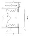
- FIG. 5Eillustrates a curved funnel-shaped portion 58 where Surface I is defined from a curve that maintains an angle greater than the critical angle for TIR but directs the light out of the lens roughly at 90 degrees to longitudinal package axis 53 .
- FIG. 5Fillustrates a bent-line funnel-shaped portion 58 where Surface I is defined from a line bent into two linear portions, each portion at an angle greater than the critical angle for TIR but directs the light out of the package roughly at 90 degrees to the package axis.
- FIG. 5Gillustrates a linear funnel-shaped portion 58 where Surface I is defined by a straight line at an angle greater than the critical angle for TIR but directs the light out of the package roughly at 90 degrees to the package axis.
- FIGS. 5E-5GSurface H works with surface I to emit light perpendicular to longitudinal package axis 53 .
- the angle defined by surface I relative to the dieis roughly 80 degrees.
- Surfaces A, B, C, D & Ehave surface normals such that the incident light ray is refracted out of the lens at approximately 90 degrees to the longitudinal package axis 53 .
- Surfaces F, G & Hare approximately parallel to direct incident light rays in order to minimize the amount of direct light transmitted through these surfaces.
- Surfaces below line Nrefract light out of the package.
- Surfaces above line Mwill direct light out of the lens through a combination of TIR and refraction. Lines M & N need to be in close proximity of each other to optimize side emission and minimize emission in the longitudinal direction.
- 5E-5Gshow two zones: zone refraction at approximately 45 degrees or more from longitudinal package axis 53 and zone TIR/refraction at up to approximately 45 degrees from longitudinal package axis 53 .
- zone refractionat approximately 45 degrees or more from longitudinal package axis 53
- zone TIR/refractionat up to approximately 45 degrees from longitudinal package axis 53 .
- FIGS. 5E-5Gan approximately 40 degree TIR/refraction zone is shown.
- the interface between the two zonesis approximately 45 degrees from the longitudinal package axis 53 .
- a distance X between Line M and Line Nis kept at a minimum in order to optimize the side extraction of light from the lens.
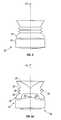
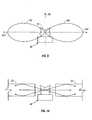
- FIG. 6illustrates a cross-section of the emission of light from LED package 40 of FIG. 4 .
- Lens 44 of LED package 40creates a radiation pattern 62 roughly perpendicular to longitudinal package axis 66 of LED package 40 .
- this radiation pattern 62is approximately perpendicular to LED package axis 66 and illustrates relative light intensity and distribution.
- This field of illumination 62surrounds LED package 40 and is roughly disk-or toroidal-shaped.
- Lightis emitted from lens 44 approximately parallel to an optical plane 64 .
- FIG. 7Aillustrates two planar light guides placed nearly end-to-end with space for at least one LED package 40 between light guides 72 .
- the side-emission of light from the LED package 40allows light to enter each light guide 72 .
- the LED package 40may also be inserted into the body of light guide 72 .
- Light guides of various shapesmay be used.
- the sides along the length of the light guidesmay be planar or taper.
- a single side emitting LED package 40may be placed at the center of a disk-shaped light guide (not shown). As light is emitted from the side of LED package 40 in 360 degrees (i.e., in all directions from the center of LED package 40 ), the light enters the light guide and is refracted and reflected throughout the entire light guide (not shown).
- the light guidecan be made from optically transmissive materials, including but not limited to PC or PMMA.
- the light guidemay be of constant thickness or tapered. Side emission of light allows efficient illumination of thin light guides with a thickness in the optimum range of 2 to 8 mm.
- FIG. 7Billustrates an example of a light guide 73 with a thickness of 5.0 mm which is greater than the height of lens 44 . As the thickness of light guide 73 is greater than the height of the lens 44 , a blind-hole 94 may be used in light guide 73 to allow coupling of the LED package 40 .
- the dimensions of lenses 44 of FIGS. 7B, 7 C & 7 Dare measured from the focal point F of lens 44 .
- FIG. 7Cillustrates an example of a light guide 75 with a thickness of 4.5 mm and equal to the height of lens 44 .
- a through-hole 96may be used in light guide 75 to allow coupling of LED package 40 .
- FIG. 7Dillustrates side-emission of light from the LED of FIG. 4 into a light guide 77 thinner than the height of lens 44 .
- a through-hole 96must be used in the light guide 77 to allow coupling of LED package 40 .
- Light guide 77is thinner than the height of lens 44 , a large portion of the light emitted from LED chip 52 will still be directed into light guide 77 as the bulk of the light emitted from LED chip 52 is emitted from the sides of lens 44 .
- the large portion of the light emitted from lens 44is targeted toward a light guide 77 that is positioned midway up the height of the lens. For example, the light emitted out the side of lens 44 near the top will be directed slightly downward and the light emitted out the side of lens 44 near the bottom will be directed slightly upward.
- the portion of light directed into light guide 77decreases as the thickness of light guide 77 relative to lens 44 decreases.
- Light guide 77may be any shape including, without limitation, straight, tapered, rectangular, round or square.
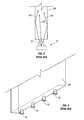
- FIG. 8illustrates a perspective view of an end-portion of a planar light guide 82 .
- the side emitting LED package 40allows LED package 40 to be placed inside light guide 82 .
- One or more holes 86are made in the body of light guide 82 with a corresponding number of LED assemblies 40 placed within holes 86 . Holes 86 may be made to any desired depth in light guide 82 , including but not limited to the entire thickness of light guide 82 .
- Lens 44 of LED package 40may not touch light guide 82 .
- a reflective coating or film 84may be placed on at least one of the ends of light guide 82 to increase the internal illumination of light guide 82 .
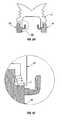
- FIG. 9Aillustrates a side-emitting LED package 40 mounted in a blind-hole 94 of a planar light guide 82 .
- Top surface 91 of blind-hole 94is approximately parallel with top surface 95 of planar light guide 82 .
- Top surface 91 of blind-hole 94may be coated with a reflective coating or film to reflect light in order to allow for a thinner light guide package with a similar coupling efficiency.
- FIG. 9Billustrates a side-emitting LED package 40 mounted in a funnel-shaped blind-hole 98 of a planar light guide 82 .
- the top surface 93 of funnel-shaped blind-hole 98is approximately parallel with funnel-shaped portion 58 of lens 44 of LED package 40 .
- Top surface 93 of blind-hole 98may be coated to reflect light in order to allow for a thinner light guide package with a similar coupling efficiency.
- the blind holecan have a flat, funnel or curved surface to assist with redirecting light emitted from the LED into the light guide.
- FIG. 9Cillustrates a side-emitting LED package 40 mounted in a v-shaped blind-hole 97 of a planar light guide 82 .
- the v-shaped top surface 99 of the blind-hole 97is approximately parallel with funnel-shaped portion 58 of lens 44 of LED package 40 .
- the blind holecan have a flat, funnel or curved surface to assist with redirecting light emitted from the LED into the light guide.
- the top surface 99 of blind-hole 97may be coated to reflect light in order to allow for a thinner light guide package with a similar coupling efficiency.
- FIG. 10illustrates a side-emitting LED package 40 mounted in a through-hole 96 of a planar light guide 82 .
- Through-hole 96allows LED package 40 to be mounted approximately perpendicular with light guide 82 .
- FIG. 11illustrates a conventional LED/reflector arrangement. It is known to use an LED package 10 with a hemispherical lens 12 in combination with a deep reflector 92 . The deep shape of the cavity of reflector 92 collimates light emitted from the hemispherical lens 12 of LED package 10 . This deep reflector cavity is required to control the light.
- a shallow, large-area reflector 102can be used in combination with a side-emitting LED package 40 to emit light over a broader area than a conventional LED package 10 .
- the longitudinal package axis 116 of the lensis approximately parallel to a radial axis 122 of reflector 102 .
- the side-emission of lightallows the walls of reflector 102 to be less deep than conventional reflectors 92 (FIG. 11 ).
- Lightis emitted from lens 144 roughly perpendicular to longitudinal package axis 116 of LED package 40 .
- Side-emitting LED package 40allows for very high collection efficiencies with shallow large area reflectors compared to conventional LEDs.
- Shallow reflectors 102collimate emitted light over a broader area than narrow, deep reflectors 92 used in combination with conventional LED assemblies 10 .
- Shallow, large-area reflector 102may be made of BMC bulk molding compound, PC, PMMA, PC/PMMA, and PEI.
- a reflective film 120 covering the inside of reflector 102could be metallized, sputtered, or the like with highly reflective materials including, without limitation, aluminum (AL), NiCr, and nickel chrome. Side-emitting LEDs can achieve higher collection efficiencies with deep or shallow reflectors than the conventional LED/deep reflector combination.
Landscapes
- Physics & Mathematics (AREA)
- General Physics & Mathematics (AREA)
- Optics & Photonics (AREA)
- Engineering & Computer Science (AREA)
- General Engineering & Computer Science (AREA)
- Led Device Packages (AREA)
- Planar Illumination Modules (AREA)
Abstract
Description
Claims (54)
Priority Applications (5)
| Application Number | Priority Date | Filing Date | Title |
|---|---|---|---|
| US09/849,084US6607286B2 (en) | 2001-05-04 | 2001-05-04 | Lens and lens cap with sawtooth portion for light emitting diode |
| EP02076672AEP1255132B1 (en) | 2001-05-04 | 2002-04-26 | Lens for light-emitting devices |
| DE60205806TDE60205806T2 (en) | 2001-05-04 | 2002-04-26 | Lens for LEDs |
| TW091108982ATW565951B (en) | 2001-05-04 | 2002-04-30 | LED lens |
| JP2002130401AJP2003008068A (en) | 2001-05-04 | 2002-05-02 | Light emitting diode lens |
Applications Claiming Priority (1)
| Application Number | Priority Date | Filing Date | Title |
|---|---|---|---|
| US09/849,084US6607286B2 (en) | 2001-05-04 | 2001-05-04 | Lens and lens cap with sawtooth portion for light emitting diode |
Publications (2)
| Publication Number | Publication Date |
|---|---|
| US20020163808A1 US20020163808A1 (en) | 2002-11-07 |
| US6607286B2true US6607286B2 (en) | 2003-08-19 |
Family
ID=25305023
Family Applications (1)
| Application Number | Title | Priority Date | Filing Date |
|---|---|---|---|
| US09/849,084Expired - LifetimeUS6607286B2 (en) | 2001-05-04 | 2001-05-04 | Lens and lens cap with sawtooth portion for light emitting diode |
Country Status (5)
| Country | Link |
|---|---|
| US (1) | US6607286B2 (en) |
| EP (1) | EP1255132B1 (en) |
| JP (1) | JP2003008068A (en) |
| DE (1) | DE60205806T2 (en) |
| TW (1) | TW565951B (en) |
Cited By (177)
| Publication number | Priority date | Publication date | Assignee | Title |
|---|---|---|---|---|
| US20030015959A1 (en)* | 2001-07-11 | 2003-01-23 | Katsuhiro Tomoda | Display unit |
| US20030021122A1 (en)* | 2001-07-30 | 2003-01-30 | Randall Stephen Michael | Illumination device utilizing displaced radiation patterns |
| US20030099113A1 (en)* | 2001-11-28 | 2003-05-29 | Matthias Gebauer | Lamp for vehicles |
| US20040070855A1 (en)* | 2002-10-11 | 2004-04-15 | Light Prescriptions Innovators, Llc, A Delaware Limited Liability Company | Compact folded-optics illumination lens |
| US20040105171A1 (en)* | 2002-12-02 | 2004-06-03 | Light Prescriptions Innovators, Llc, A Delaware Limited Liability Company | Asymmetric TIR lenses producing off-axis beams |
| US20040189933A1 (en)* | 2002-12-02 | 2004-09-30 | Light Prescription Innovators, Llc | Apparatus and method for use in fulfilling illumination prescription |
| US20040223315A1 (en)* | 2003-03-03 | 2004-11-11 | Toyoda Gosei Co., Ltd. | Light emitting apparatus and method of making same |
| US20040228131A1 (en)* | 2003-05-13 | 2004-11-18 | Light Prescriptions Innovators, Llc, A Delaware Limited Liability Company | Optical device for LED-based light-bulb substitute |
| US20050017619A1 (en)* | 2003-07-21 | 2005-01-27 | Sheng-Chih Wan | Modified high-brightness flat lamp structure |
| US20050024744A1 (en)* | 2003-07-29 | 2005-02-03 | Light Prescriptions Innovators, Llc | Circumferentially emitting luminaires and lens-elements formed by transverse-axis profile-sweeps |
| US20050063188A1 (en)* | 2003-09-19 | 2005-03-24 | Mattel, Inc. | Multidirectional light emitting diode unit |
| DE10339879A1 (en)* | 2003-08-29 | 2005-03-24 | Hella Kgaa Hueck & Co. | Opto-electronic device for a motor vehicle |
| US20050068777A1 (en)* | 2003-09-25 | 2005-03-31 | Dragoslav Popovic | Modular LED light and method |
| US20050086032A1 (en)* | 2003-07-28 | 2005-04-21 | Light Prescriptions Innovators, Llc | Three-dimensional simultaneous multiple-surface method and free-form illumination-optics designed therefrom |
| US20050129358A1 (en)* | 2003-02-04 | 2005-06-16 | Light Prescriptions Innovators, Llc A Delaware Limited Liability Company | Etendue-squeezing illumination optics |
| US20050152146A1 (en)* | 2002-05-08 | 2005-07-14 | Owen Mark D. | High efficiency solid-state light source and methods of use and manufacture |
| US20050219857A1 (en)* | 2002-03-14 | 2005-10-06 | Schefenacker Vision Systems Germany Gmbh & Co. Kg | Luminous unit, particularly as an additional light in sideview mirrors of motor vehicles |
| US20050225988A1 (en)* | 2003-05-13 | 2005-10-13 | Light Prescriptions Innovators, Llc | Optical device for LED-based lamp |
| US20050230600A1 (en)* | 2004-03-30 | 2005-10-20 | Olson Steven J | LED array having array-based LED detectors |
| US20050231713A1 (en)* | 2004-04-19 | 2005-10-20 | Owen Mark D | Imaging semiconductor structures using solid state illumination |
| US6964507B2 (en) | 2003-04-25 | 2005-11-15 | Everbrite, Llc | Sign illumination system |
| US20060018122A1 (en)* | 2004-07-23 | 2006-01-26 | Negley Gerald H | Reflective optical elements for semiconductor light emitting devices |
| US20060034097A1 (en)* | 2004-08-11 | 2006-02-16 | Samsung Electro-Mechanics Co., Ltd. | Light emitting diode lens and backlight apparatus having the same |
| US20060038196A1 (en)* | 2004-08-18 | 2006-02-23 | Unity Opto Technology Co., Ltd. | Sideway-emission light emitting diode |
| US20060050530A1 (en)* | 2004-08-30 | 2006-03-09 | Schefenacker Vision Systems Germany Gmbh | Lighting unit having a plurality of curved surface elements |
| US20060067640A1 (en)* | 2004-09-24 | 2006-03-30 | Min-Hsun Hsieh | Illumination package |
| US7021801B2 (en) | 2002-09-19 | 2006-04-04 | Everbrite, Llc | High-intensity directional light |
| US20060076568A1 (en)* | 2004-10-12 | 2006-04-13 | Cree, Inc. | Side-emitting optical coupling device |
| US20060083003A1 (en)* | 2004-10-15 | 2006-04-20 | Samsung Electro-Mechanics Co., Ltd. | Lens for LED light sources |
| US20060083000A1 (en)* | 2004-10-18 | 2006-04-20 | Ju-Young Yoon | Light emitting diode and lens for the same |
| US20060091429A1 (en)* | 2004-11-03 | 2006-05-04 | Samsung Electronics Co., Ltd. | Light emitting diode and lens for the same |
| US20060092663A1 (en)* | 2004-10-29 | 2006-05-04 | Noh Ji-Whan | Side light-emitting device, backlight unit having the side light-emitting device, and liquid crystal display apparatus employing the backlight unit |
| US20060203513A1 (en)* | 2005-03-08 | 2006-09-14 | Tomio Aoki | Backlight device and liquid crystal display |
| US20060216865A1 (en)* | 2004-03-18 | 2006-09-28 | Phoseon Technology, Inc. | Direct cooling of leds |
| US20060226436A1 (en)* | 2005-04-12 | 2006-10-12 | Coretronic Corporation | Lens assembly for sideward light emission |
| US20060245083A1 (en)* | 2005-04-19 | 2006-11-02 | Coretronic Corporation | Lens for sideward light emission |
| US20060274547A1 (en)* | 2005-01-06 | 2006-12-07 | Au Optronics Corp. | Backlight module and illumination device thereof |
| US20060291205A1 (en)* | 2005-06-24 | 2006-12-28 | Lg Philips Lcd Co., Ltd. | Backlight assembly including light emitting diode and display device including the same |
| US20070030678A1 (en)* | 2003-10-31 | 2007-02-08 | Phoseon Technology, Inc. | Series wiring of highly reliable light sources |
| US20070041186A1 (en)* | 2005-08-22 | 2007-02-22 | Siew Kim Tan | Opto-electronic package, and methods and systems for making and using same |
| US20070041210A1 (en)* | 2005-08-08 | 2007-02-22 | Konica Minolta Opto Inc. | Optical element and lighting device provided therewith |
| US20070051964A1 (en)* | 2004-04-12 | 2007-03-08 | Owen Mark D | High density led array |
| US20070109790A1 (en)* | 2003-10-31 | 2007-05-17 | Phoseon Technology, Inc. | Collection optics for led array with offset hemispherical or faceted surfaces |
| US20070115660A1 (en)* | 2005-11-19 | 2007-05-24 | Samsung Electronics Co., Ltd | Backlight unit and liquid crystal display comprising the same |
| US20070121340A1 (en)* | 2005-11-25 | 2007-05-31 | Sony Corporation | Light guide plate, backlight unit and method of manufacturing the same, and liquid crystal display |
| US20070154823A1 (en)* | 2005-12-30 | 2007-07-05 | Phoseon Technology, Inc. | Multi-attribute light effects for use in curing and other applications involving photoreactions and processing |
| US20070200118A1 (en)* | 2005-12-21 | 2007-08-30 | Epstein Kenneth A | Led light confinement element |
| US20070217195A1 (en)* | 2006-03-15 | 2007-09-20 | Bright Led Electronics Corp. | Light-emitting device and a lens thereof |
| US20070258241A1 (en)* | 2006-05-02 | 2007-11-08 | 3M Innovative Properties Company | Led package with non-bonded converging optical element |
| US20070257270A1 (en)* | 2006-05-02 | 2007-11-08 | 3M Innovative Properties Company | Led package with wedge-shaped optical element |
| US20070258014A1 (en)* | 2006-05-02 | 2007-11-08 | Ati Technologies Inc. | Field sequence detector, method and video device |
| US20070257271A1 (en)* | 2006-05-02 | 2007-11-08 | 3M Innovative Properties Company | Led package with encapsulated converging optical element |
| US20070258246A1 (en)* | 2006-05-02 | 2007-11-08 | 3M Innovative Properties Company | Led package with compound converging optical element |
| US20070274667A1 (en)* | 2006-05-10 | 2007-11-29 | Cree, Inc. | Methods and apparatus for directing light emitting diode output light |
| US20070273984A1 (en)* | 2006-05-25 | 2007-11-29 | Industrial Technology Research Institute | Light Guide Lens and Light Emitting Diode Package Structure having the Light Guide Lens |
| US20070284993A1 (en)* | 2004-10-07 | 2007-12-13 | Seoul Semiconductor Co., Ltd. | Side Illumination Lens and Luminescent Device Using the Same |
| US20080002412A1 (en)* | 2006-06-30 | 2008-01-03 | Toshiaki Tanaka | Liquid crystal display device |
| US20080012034A1 (en)* | 2006-07-17 | 2008-01-17 | 3M Innovative Properties Company | Led package with converging extractor |
| US20080019136A1 (en)* | 2006-07-20 | 2008-01-24 | Jens Mertens | Light unit with a light-emitting diode with an integrated light-deflecting body |
| US20080062707A1 (en)* | 2006-09-08 | 2008-03-13 | Chao Hsien Wu | LED illuminator collimation module and its holder |
| US20080074888A1 (en)* | 2006-09-21 | 2008-03-27 | Hon Hai Precision Industry Co., Ltd. | Light emitting diode having reflective member and method for making the same |
| US20080089062A1 (en)* | 2006-10-12 | 2008-04-17 | Dicon Fiberoptics, Inc. | Solid-state lateral emitting optical system |
| US20080111146A1 (en)* | 2006-11-15 | 2008-05-15 | The Regents Of The University Of California | Standing transparent mirrorless light emitting diode |
| US20080111471A1 (en)* | 2005-01-19 | 2008-05-15 | Osram Opto Semiconductors Gmbh | Lighting Device |
| US20080121918A1 (en)* | 2006-11-15 | 2008-05-29 | The Regents Of The University Of California | High light extraction efficiency sphere led |
| US20080128730A1 (en)* | 2006-11-15 | 2008-06-05 | The Regents Of The University Of California | Textured phosphor conversion layer light emitting diode |
| US20080149959A1 (en)* | 2006-12-11 | 2008-06-26 | The Regents Of The University Of California | Transparent light emitting diodes |
| US20080149949A1 (en)* | 2006-12-11 | 2008-06-26 | The Regents Of The University Of California | Lead frame for transparent and mirrorless light emitting diodes |
| US20080151551A1 (en)* | 2006-12-20 | 2008-06-26 | Industrial Technology Research Institute | Lens cap and light emitting diode package structure using the same |
| US20080192479A1 (en)* | 2004-09-08 | 2008-08-14 | Mario Wanninger | Laterally Emitting, Radiation-Generating Component and Lens for One Such Component |
| US20080198604A1 (en)* | 2007-02-20 | 2008-08-21 | Sekonix Co., Ltd. | Lighting apparatus using filter and condenser for led illumination |
| US20080239722A1 (en)* | 2007-04-02 | 2008-10-02 | Ruud Lighting, Inc. | Light-Directing LED Apparatus |
| US20080271776A1 (en)* | 2007-05-01 | 2008-11-06 | Morgan Solar Inc. | Light-guide solar panel and method of fabrication thereof |
| US20080273332A1 (en)* | 2005-10-21 | 2008-11-06 | Koninklijke Philips Electronics, N.V. | Light Device |
| US20080283861A1 (en)* | 2004-06-04 | 2008-11-20 | Cree, Inc. | Power light emitting die package with reflecting lens and the method of making the same |
| US20080297020A1 (en)* | 2005-09-30 | 2008-12-04 | Osram Opto Semiconductors Gmbh | Illuminiation Arrangement |
| US7461949B2 (en) | 2002-05-08 | 2008-12-09 | Phoseon Technology, Inc. | Methods and systems relating to solid state light sources for use in industrial processes |
| US20080304273A1 (en)* | 2007-06-08 | 2008-12-11 | Roy Clark | Device For Improved Illumination Efficiency |
| US20080310177A1 (en)* | 2007-06-14 | 2008-12-18 | Roy Clark | Compact illumination device |
| US20090067175A1 (en)* | 2007-01-04 | 2009-03-12 | Bright Led Electronics Corp. | Lens for use with a light-emitting element and light source device including the lens |
| US20090071467A1 (en)* | 2005-07-28 | 2009-03-19 | Light Prescriptions Innovators, Llc | Multi-junction solar cells with a homogenizer system and coupled non-imaging light concentrator |
| US20090086508A1 (en)* | 2007-09-27 | 2009-04-02 | Philips Lumileds Lighting Company, Llc | Thin Backlight Using Low Profile Side Emitting LEDs |
| US20090103320A1 (en)* | 2007-10-22 | 2009-04-23 | Roy Clark | Cross bin illumination system |
| US7525126B2 (en) | 2006-05-02 | 2009-04-28 | 3M Innovative Properties Company | LED package with converging optical element |
| CN100487496C (en)* | 2007-10-16 | 2009-05-13 | 东莞勤上光电股份有限公司 | Secondary optical lens |
| US20090121250A1 (en)* | 2006-11-15 | 2009-05-14 | Denbaars Steven P | High light extraction efficiency light emitting diode (led) using glass packaging |
| US20090129097A1 (en)* | 2007-11-21 | 2009-05-21 | Cr Control Systems, Inc. | Side-emitting lens for led lamp |
| WO2009066209A1 (en)* | 2007-11-20 | 2009-05-28 | Koninklijke Philips Electronics N.V. | Collimating light emitting apparatus and method |
| US20090180276A1 (en)* | 2006-07-14 | 2009-07-16 | Light Prescriptions Innovators, Llc | Brightness-enhancing film |
| US20090213575A1 (en)* | 2005-12-16 | 2009-08-27 | Osram Opto Semiconductors Gmbh | Illumination device |
| US20090211130A1 (en)* | 2005-05-19 | 2009-08-27 | Hoffman Joseph A | Thin internally illuminated sign |
| US20090225543A1 (en)* | 2008-03-05 | 2009-09-10 | Cree, Inc. | Optical system for batwing distribution |
| US20090237956A1 (en)* | 2008-03-19 | 2009-09-24 | Fu Zhun Precision Industry (Shen Zhen) Co., Ltd. | Light emitting diode assembly |
| US20090251897A1 (en)* | 2008-04-08 | 2009-10-08 | Ushiodenki Kabushiki Kaisha | Led light source device |
| US20090268471A1 (en)* | 2008-04-24 | 2009-10-29 | Chin-Chung Chen | Lens device and illumination apparatus having the same |
| US7638808B2 (en) | 2004-03-18 | 2009-12-29 | Phoseon Technology, Inc. | Micro-reflectors on a substrate for high-density LED array |
| US20100046218A1 (en)* | 2008-08-21 | 2010-02-25 | Hon Hai Precision Industry Co., Ltd. | Light source assembly |
| CN101660706A (en)* | 2008-12-31 | 2010-03-03 | 广东昭信光电科技有限公司 | LED lens for realizing light beam control |
| US20100073927A1 (en)* | 2008-09-21 | 2010-03-25 | Ian Lewin | Lens for Solid-State Light-Emitting Device |
| US20100091498A1 (en)* | 2008-10-10 | 2010-04-15 | Koninklijke Philips Electronics N.V. | Low profile side emission tir lens for led |
| US20100102334A1 (en)* | 2006-10-16 | 2010-04-29 | Koninklijke Philips Electronics N.V. | Lighting device |
| US20100118531A1 (en)* | 2007-04-05 | 2010-05-13 | Koninklijke Philips Electronics N.V. | Light-beam shaper |
| US20100124055A1 (en)* | 2008-11-18 | 2010-05-20 | Reflexite Corporation | Side-emitting optical elements and methods thereof |
| US20100128488A1 (en)* | 2008-11-21 | 2010-05-27 | Dbm Reflex Enterprises Inc. | Solid state optical illumination apparatus |
| US20100135028A1 (en)* | 2007-08-09 | 2010-06-03 | Sharp Kabushiki Kaisha | Light emitting device and lighting device having the same |
| US20100149804A1 (en)* | 2008-12-12 | 2010-06-17 | Abl Ip Holding Llc | Light Emitting Diode Luminaires and Applications Thereof |
| US7766509B1 (en) | 2008-06-13 | 2010-08-03 | Lumec Inc. | Orientable lens for an LED fixture |
| US20100195333A1 (en)* | 2009-01-30 | 2010-08-05 | Gary Eugene Schaefer | Led optical assembly |
| US7798675B2 (en) | 2006-08-11 | 2010-09-21 | Light Prescriptions Innovators, Llc | LED luminance-enhancement and color-mixing by rotationally multiplexed beam-combining |
| US20100259706A1 (en)* | 2008-06-23 | 2010-10-14 | Takashi Kuwaharada | Light-emitting device, surface light-emitting apparatus, display system |
| US20100271829A1 (en)* | 2008-06-13 | 2010-10-28 | Lumec Inc. | Orientable lens for a led fixture |
| US20100283078A1 (en)* | 2006-11-15 | 2010-11-11 | The Regents Of The University Of California | Transparent mirrorless light emitting diode |
| US7841750B2 (en) | 2008-08-01 | 2010-11-30 | Ruud Lighting, Inc. | Light-directing lensing member with improved angled light distribution |
| US20110002141A1 (en)* | 2009-07-02 | 2011-01-06 | Hannstar Display Corp. | Backlight module for liquid crystal display |
| US20110011449A1 (en)* | 2007-05-01 | 2011-01-20 | Morgan Solar Inc. | Light-guide solar panel and method of fabrication thereof |
| US20110051413A1 (en)* | 2009-08-25 | 2011-03-03 | Abl Ip Holding Llc | Optic shielding |
| US20110148270A1 (en)* | 2009-12-21 | 2011-06-23 | Malek Bhairi | Spherical light output LED lens and heat sink stem system |
| US20110204242A1 (en)* | 2010-02-23 | 2011-08-25 | Abl Ip Holding Llc | Manufacturing Methods for Collimators |
| US20110242846A1 (en)* | 2010-04-01 | 2011-10-06 | Jun Seok Park | Light unit and display apparatus having the same |
| US20110249467A1 (en)* | 2008-12-18 | 2011-10-13 | Koninklijke Philips Electronics N.V. | Light emitting device creating decorative light effects in a luminaire |
| DE102010019436A1 (en)* | 2010-05-05 | 2011-11-10 | Christian Bartenbach | Wall and / or ceiling light |
| US8075147B2 (en) | 2003-05-13 | 2011-12-13 | Light Prescriptions Innovators, Llc | Optical device for LED-based lamp |
| US20120114323A1 (en)* | 2010-11-10 | 2012-05-10 | Jae-Sung You | Flash lens and flash module employing the same |
| US8328403B1 (en) | 2012-03-21 | 2012-12-11 | Morgan Solar Inc. | Light guide illumination devices |
| US20120328242A1 (en)* | 2011-06-25 | 2012-12-27 | Andreas Hesse | Optical system for coupling light from point light sources into a flat light guide |
| US8348475B2 (en) | 2008-05-23 | 2013-01-08 | Ruud Lighting, Inc. | Lens with controlled backlight management |
| US8384999B1 (en) | 2012-01-09 | 2013-02-26 | Cerr Limited | Optical modules |
| US20130051031A1 (en)* | 2011-08-31 | 2013-02-28 | National Central University | Reflective street light with wide divergence angle |
| US8388193B2 (en) | 2008-05-23 | 2013-03-05 | Ruud Lighting, Inc. | Lens with TIR for off-axial light distribution |
| US8393777B2 (en) | 2005-07-28 | 2013-03-12 | Light Prescriptions Innovators, Llc | Etendue-conserving illumination-optics for backlights and frontlights |
| US8419232B2 (en) | 2005-07-28 | 2013-04-16 | Light Prescriptions Innovators, Llc | Free-form lenticular optical elements and their application to condensers and headlamps |
| US8434913B2 (en) | 2008-05-30 | 2013-05-07 | Koninklijke Philips Electronics N.V. | Round illumination device |
| US8450847B2 (en) | 2009-01-15 | 2013-05-28 | Osram Opto Semiconductors Gmbh | Optoelectronic semiconductor chip fitted with a carrier |
| US8576406B1 (en) | 2009-02-25 | 2013-11-05 | Physical Optics Corporation | Luminaire illumination system and method |
| USD697664S1 (en) | 2012-05-07 | 2014-01-14 | Cree, Inc. | LED lens |
| US20140029268A1 (en)* | 2012-07-27 | 2014-01-30 | Byeongguk MIN | Lighting device |
| TWI426208B (en)* | 2011-08-01 | 2014-02-11 | Univ Kun Shan | Light-guiding module and lighting apparatus |
| US8885995B2 (en) | 2011-02-07 | 2014-11-11 | Morgan Solar Inc. | Light-guide solar energy concentrator |
| USD718490S1 (en) | 2013-03-15 | 2014-11-25 | Cree, Inc. | LED lens |
| US20150062882A1 (en)* | 2013-08-30 | 2015-03-05 | Genius Electronic Optical Co., Ltd. | Lamp with Lateral Illumination Capability |
| CN101939583B (en)* | 2008-02-06 | 2015-04-08 | 奥斯兰姆有限公司 | Lighting module, lighting device and lighting method |
| TWI490556B (en)* | 2013-08-21 | 2015-07-01 | Advanced Optoelectronic Tech | Lens and light emitting component having the lens |
| US9166127B2 (en) | 2009-03-31 | 2015-10-20 | Koha Co., Ltd. | Light source module |
| US20150369454A1 (en)* | 2013-02-14 | 2015-12-24 | Lg Electronics Inc | Display apparatus |
| US9255686B2 (en) | 2009-05-29 | 2016-02-09 | Cree, Inc. | Multi-lens LED-array optic system |
| US9337373B2 (en) | 2007-05-01 | 2016-05-10 | Morgan Solar Inc. | Light-guide solar module, method of fabrication thereof, and panel made therefrom |
| US9423096B2 (en) | 2008-05-23 | 2016-08-23 | Cree, Inc. | LED lighting apparatus |
| US9514663B2 (en) | 2012-07-30 | 2016-12-06 | Ultravision Technologies, Llc | Method of uniformly illuminating a billboard |
| US9523479B2 (en) | 2014-01-03 | 2016-12-20 | Cree, Inc. | LED lens |
| US9541258B2 (en) | 2012-02-29 | 2017-01-10 | Cree, Inc. | Lens for wide lateral-angle distribution |
| US9541257B2 (en) | 2012-02-29 | 2017-01-10 | Cree, Inc. | Lens for primarily-elongate light distribution |
| US20170084802A1 (en)* | 2015-09-23 | 2017-03-23 | Hon Hai Precision Industry Co., Ltd. | Optical lens for light emitting diode device |
| US20170184255A1 (en)* | 2015-12-28 | 2017-06-29 | Tien Yang Wang | Led lamps with improved light pattern |
| US10007115B2 (en) | 2015-08-12 | 2018-06-26 | Daqri, Llc | Placement of a computer generated display with focal plane at finite distance using optical devices and a see-through head-mounted display incorporating the same |
| US10054290B2 (en) | 2013-10-23 | 2018-08-21 | The Chamberlain Group, Inc. | Movable barrier operator light distribution |
| WO2019067647A1 (en)* | 2017-09-26 | 2019-04-04 | DMF, Inc. | Folded optics methods and apparatus for improving efficiency of led-based luminaires |
| US10408429B2 (en) | 2012-02-29 | 2019-09-10 | Ideal Industries Lighting Llc | Lens for preferential-side distribution |
| US10464472B2 (en) | 2016-11-18 | 2019-11-05 | Rebo Lighting & Electronics, Llc | Illumination assembly for a vehicle |
| US10468566B2 (en) | 2017-04-10 | 2019-11-05 | Ideal Industries Lighting Llc | Hybrid lens for controlled light distribution |
| US10488666B2 (en) | 2018-02-10 | 2019-11-26 | Daqri, Llc | Optical waveguide devices, methods and systems incorporating same |
| US10649209B2 (en) | 2016-07-08 | 2020-05-12 | Daqri Llc | Optical combiner apparatus |
| USD901752S1 (en) | 2019-01-25 | 2020-11-10 | Eaton Intelligent Power Limited | Optical structure |
| USD903187S1 (en) | 2019-01-25 | 2020-11-24 | Eaton Intelligent Power Limited | Optical structure |
| US11125993B2 (en) | 2018-12-10 | 2021-09-21 | Facebook Technologies, Llc | Optical hyperfocal reflective systems and methods, and augmented reality and/or virtual reality displays incorporating same |
| US11221494B2 (en) | 2018-12-10 | 2022-01-11 | Facebook Technologies, Llc | Adaptive viewport optical display systems and methods |
| US11236887B2 (en) | 2019-01-25 | 2022-02-01 | Eaton Intelligent Power Limited | Optical structures for light emitting diodes (LEDs) |
| US11275436B2 (en) | 2017-01-11 | 2022-03-15 | Rpx Corporation | Interface-based modeling and design of three dimensional spaces using two dimensional representations |
| USD956602S1 (en) | 2020-03-10 | 2022-07-05 | Sirius Signal, LLC | Visual distress signal device |
| US20220221760A1 (en)* | 2021-01-13 | 2022-07-14 | K-Tronics (Suzhou) Technology Co., Ltd. | Reflective sheet and manufacturing method thereof, backlight module, and display device |
| US20220373142A1 (en)* | 2019-10-28 | 2022-11-24 | Signify Holding B.V. | Color mixing with total internal reflector and ring reflector |
| US11587362B2 (en) | 2020-12-16 | 2023-02-21 | Lenovo (Singapore) Pte. Ltd. | Techniques for determining sign language gesture partially shown in image(s) |
| US11592166B2 (en) | 2020-05-12 | 2023-02-28 | Feit Electric Company, Inc. | Light emitting device having improved illumination and manufacturing flexibility |
| US11662513B2 (en) | 2019-01-09 | 2023-05-30 | Meta Platforms Technologies, Llc | Non-uniform sub-pupil reflectors and methods in optical waveguides for AR, HMD and HUD applications |
| WO2023200330A1 (en)* | 2022-04-15 | 2023-10-19 | Avialite Sdn. Bhd. | Obstruction lighting optic device for aviation |
| US11863730B2 (en) | 2021-12-07 | 2024-01-02 | Snap Inc. | Optical waveguide combiner systems and methods |
| US11876042B2 (en) | 2020-08-03 | 2024-01-16 | Feit Electric Company, Inc. | Omnidirectional flexible light emitting device |
| US11912378B2 (en) | 2019-08-01 | 2024-02-27 | Sirius Signal, LLC | Visual distress signal device |
Families Citing this family (86)
| Publication number | Priority date | Publication date | Assignee | Title |
|---|---|---|---|---|
| US6598998B2 (en)* | 2001-05-04 | 2003-07-29 | Lumileds Lighting, U.S., Llc | Side emitting light emitting device |
| US6679621B2 (en)* | 2002-06-24 | 2004-01-20 | Lumileds Lighting U.S., Llc | Side emitting LED and lens |
| JP4182784B2 (en)* | 2003-03-14 | 2008-11-19 | 豊田合成株式会社 | Light emitting device and manufacturing method thereof |
| JP4182783B2 (en)* | 2003-03-14 | 2008-11-19 | 豊田合成株式会社 | LED package |
| US20040183081A1 (en)* | 2003-03-20 | 2004-09-23 | Alexander Shishov | Light emitting diode package with self dosing feature and methods of forming same |
| EP1544074B1 (en)* | 2003-12-17 | 2006-11-02 | Pintsch Bamag Antriebs- und Verkehrstechnik GmbH | Headlamp and signaling lights for a railway vehicle. |
| US7172324B2 (en)* | 2004-01-05 | 2007-02-06 | Leotek Electronics Corporation | Internally illuminated light panel with LED modules having light redirecting devices |
| GB0407951D0 (en) | 2004-04-08 | 2004-05-12 | Pilkington Plc | Vehicle glazing |
| US7280288B2 (en)* | 2004-06-04 | 2007-10-09 | Cree, Inc. | Composite optical lens with an integrated reflector |
| US7201495B2 (en)* | 2004-08-03 | 2007-04-10 | Philips Lumileds Lighting Company, Llc | Semiconductor light emitting device package with cover with flexible portion |
| KR100677135B1 (en)* | 2004-09-25 | 2007-02-02 | 삼성전자주식회사 | Side emitting device, back light unit using the same as a light source and liquid display apparatus employing it |
| JP3875247B2 (en)* | 2004-09-27 | 2007-01-31 | 株式会社エンプラス | Light emitting device, surface light source device, display device, and light flux controlling member |
| TWI317829B (en)* | 2004-12-15 | 2009-12-01 | Epistar Corp | Led illumination device and application thereof |
| KR101107684B1 (en)* | 2004-12-21 | 2012-01-25 | 엘지디스플레이 주식회사 | LED array and backlight unit using the same |
| US7584534B2 (en)* | 2005-01-10 | 2009-09-08 | Perceptron, Inc. | Remote inspection device |
| KR101112552B1 (en) | 2005-03-08 | 2012-02-15 | 삼성전자주식회사 | Lens for light emitting diode, light emitting diode, backlight assembly and liquid crystal display device comprising the same |
| KR100593933B1 (en) | 2005-03-18 | 2006-06-30 | 삼성전기주식회사 | Side emitting type light emitting diode package having scattering region and backlight device comprising the same |
| CN1866552A (en) | 2005-05-18 | 2006-11-22 | 光宝科技股份有限公司 | Light traveling direction changing unit, module containing same and light emitting diode assembly |
| EP1886358A1 (en)* | 2005-05-20 | 2008-02-13 | Datasensor S.p.A. | Lighting fixture for projecting a light beam at a variable projection angle, and relative operating method |
| US20060285311A1 (en)* | 2005-06-19 | 2006-12-21 | Chih-Li Chang | Light-emitting device, backlight module, and liquid crystal display using the same |
| NL1029583C2 (en)* | 2005-07-21 | 2007-01-25 | Imt B V | Explosion-proof fixture. |
| WO2007018927A2 (en)* | 2005-07-22 | 2007-02-15 | Illumination Management Solutions, Inc. | A light-conducting pedestal configuration for an led |
| JP2007042938A (en)* | 2005-08-04 | 2007-02-15 | Nichia Chem Ind Ltd | Optical device |
| JP4870950B2 (en)* | 2005-08-09 | 2012-02-08 | 株式会社光波 | Light emitting light source unit and planar light emitting device using the same |
| KR100835064B1 (en) | 2005-09-16 | 2008-06-03 | 삼성전기주식회사 | Total internal reflection micro lens array |
| US7703965B2 (en)* | 2005-09-23 | 2010-04-27 | Koninklijke Philips Electronics N.V. | Diffusing light system with light collector |
| JP4724618B2 (en) | 2005-11-11 | 2011-07-13 | 株式会社 日立ディスプレイズ | LIGHTING DEVICE AND LIQUID CRYSTAL DISPLAY DEVICE USING THE SAME |
| US8465183B2 (en)* | 2005-12-14 | 2013-06-18 | Koninklijke Philips Electronics N.V. | Lighting device and method for manufacturing same |
| CN101346583B (en) | 2005-12-27 | 2011-11-23 | 昭和电工株式会社 | Light guide member, flat light source device and display device |
| US7772604B2 (en) | 2006-01-05 | 2010-08-10 | Illumitex | Separate optical device for directing light from an LED |
| KR101333023B1 (en) | 2006-01-16 | 2013-11-26 | 코닌클리케 필립스 엔.브이. | Lamp module and lighting device comprising such a lamp module |
| KR101222152B1 (en)* | 2006-02-06 | 2013-01-14 | 삼성디스플레이 주식회사 | Backlight assembly and display device having the same |
| JP4891626B2 (en)* | 2006-02-15 | 2012-03-07 | 株式会社 日立ディスプレイズ | Liquid crystal display |
| FR2899310B1 (en)* | 2006-03-31 | 2009-11-20 | Valeo Vision | LIGHTING OR SIGNALING DEVICE WITH EXTENDED LIGHTING AREA FOR MOTOR VEHICLE |
| CN102418865B (en)* | 2006-07-11 | 2015-09-09 | 株式会社光波 | Light source module, face luminescence component and surface illuminating device |
| JP4533352B2 (en)* | 2006-08-09 | 2010-09-01 | 昭和電工株式会社 | Light emitting device, display device, and cover mounting member |
| WO2008042351A2 (en) | 2006-10-02 | 2008-04-10 | Illumitex, Inc. | Led system and method |
| KR101221292B1 (en) | 2006-11-30 | 2013-01-11 | 엘지디스플레이 주식회사 | Light Emitting Diode Cluster and Backlight Unit using the same |
| WO2008090574A1 (en) | 2007-01-26 | 2008-07-31 | Sic Divisione Elettronica S.R.L. | Lens for a light emitting diode and manufacturing method therefor |
| JP5056064B2 (en)* | 2007-02-23 | 2012-10-24 | パナソニック株式会社 | LED device and lighting device including the same |
| JP5188077B2 (en)* | 2007-03-02 | 2013-04-24 | 株式会社光波 | Light direction changing element and planar light emitting device |
| JP2008305940A (en)* | 2007-06-07 | 2008-12-18 | Showa Denko Kk | Display device, cap, light emitting device, and manufacturing method thereof |
| CN101373223B (en)* | 2007-08-20 | 2012-09-26 | 香港应用科技研究院有限公司 | Optical element and backlight module including same |
| US8186855B2 (en)* | 2007-10-01 | 2012-05-29 | Wassel James J | LED lamp apparatus and method of making an LED lamp apparatus |
| JP2009139190A (en)* | 2007-12-05 | 2009-06-25 | Nippon Ceramic Co Ltd | Resin molding optical lens |
| JP2011512037A (en) | 2008-02-08 | 2011-04-14 | イルミテックス, インコーポレイテッド | System and method for emitter layer shaping |
| JP5150335B2 (en)* | 2008-03-28 | 2013-02-20 | スタンレー電気株式会社 | Light guiding lens |
| CN101615642A (en)* | 2008-06-25 | 2009-12-30 | 富准精密工业(深圳)有限公司 | led |
| DE102008061032A1 (en)* | 2008-12-08 | 2010-06-10 | Osram Opto Semiconductors Gmbh | lighting device |
| TW201034256A (en) | 2008-12-11 | 2010-09-16 | Illumitex Inc | Systems and methods for packaging light-emitting diode devices |
| JP5118617B2 (en)* | 2008-12-22 | 2013-01-16 | パナソニック株式会社 | Lighting lens, light emitting device, surface light source, and liquid crystal display device |
| US8449128B2 (en) | 2009-08-20 | 2013-05-28 | Illumitex, Inc. | System and method for a lens and phosphor layer |
| US8585253B2 (en) | 2009-08-20 | 2013-11-19 | Illumitex, Inc. | System and method for color mixing lens array |
| US20110083741A1 (en)* | 2009-10-01 | 2011-04-14 | RNY Solar LLC | Multiconverter system comprising spectral separating reflector assembly and methods thereof |
| DE102009053422A1 (en)* | 2009-11-19 | 2011-06-01 | Erco Gmbh | Lens element for a light source u. a. |
| TWI422074B (en)* | 2010-01-07 | 2014-01-01 | 首爾半導體股份有限公司 | Aspherical LED lens and light-emitting element containing the same |
| KR101144635B1 (en) | 2010-03-30 | 2012-05-08 | 서울반도체 주식회사 | Aspherical led lens and light emitting device for backlight having the same |
| US10495296B2 (en)* | 2010-03-31 | 2019-12-03 | Signify North America Corporation | Integral conduit modular lighting |
| CN102214766A (en)* | 2010-04-02 | 2011-10-12 | 游森溢 | Light-emitting diode packaging structure |
| WO2012026843A1 (en)* | 2010-08-27 | 2012-03-01 | Общество с ограниченной ответственностью "ДиС ПЛЮС" | Correcting lens for a light-emitting diode |
| US8395310B2 (en)* | 2011-03-16 | 2013-03-12 | Bridgelux, Inc. | Method and apparatus for providing omnidirectional illumination using LED lighting |
| EP2530372A1 (en) | 2011-05-30 | 2012-12-05 | Odelo GmbH | Light guide element for motor vehicle lights |
| JP5095000B1 (en)* | 2011-08-11 | 2012-12-12 | 国分電機株式会社 | LED lighting device |
| SI2587120T1 (en) | 2011-10-27 | 2016-07-29 | Odelo Gmbh | Light guide and automotive vehicle equipped with such a light guide |
| KR101219125B1 (en) | 2012-02-15 | 2013-01-10 | 주식회사 새롬텍 | Apparatus for spreading of the led-illuminator |
| DE102012106624A1 (en)* | 2012-04-04 | 2013-10-10 | Siteco Beleuchtungstechnik Gmbh | Lens element, in particular for emergency lighting module |
| KR101424537B1 (en)* | 2012-04-23 | 2014-07-31 | 주식회사 포스코엘이디 | Optical semiconductor based illuminating apparatus |
| KR101491207B1 (en)* | 2012-07-18 | 2015-02-06 | 엘지이노텍 주식회사 | Display device and light emitting device |
| KR102023540B1 (en)* | 2012-08-08 | 2019-09-24 | 엘지이노텍 주식회사 | Member for controlling luminous flux, display device, and light emitting device |
| US9046242B2 (en) | 2012-08-10 | 2015-06-02 | Groupe Ledel Inc. | Light dispersion device |
| JP2014093129A (en) | 2012-10-31 | 2014-05-19 | Toshiba Lighting & Technology Corp | Light-emitting unit and luminaire |
| KR101488382B1 (en) | 2012-11-05 | 2015-01-30 | (주)애니캐스팅 | Side emitting light emitting diode lens, back light unit and display device including the same |
| CN103982855B (en)* | 2013-02-08 | 2017-01-11 | 香港理工大学 | lens and light-emitting device |
| KR101524914B1 (en)* | 2013-03-28 | 2015-06-01 | 엘지이노텍 주식회사 | Light diffusion device, and light emitting device array unit having the same |
| KR20140123134A (en)* | 2013-04-10 | 2014-10-22 | 삼성전자주식회사 | Reflective diffusion lens and lighting installation |
| GB201322135D0 (en) | 2013-12-16 | 2014-01-29 | Phyneos Ltd | Safety lantern |
| US9732936B2 (en) | 2014-01-21 | 2017-08-15 | Bridgelux Inc. | Optics for chip-on-board road and area lighting |
| CN111063787A (en)* | 2014-01-23 | 2020-04-24 | 亮锐控股有限公司 | Light emitting device with self-aligned preformed lens |
| CN103953867A (en)* | 2014-05-05 | 2014-07-30 | 立达信绿色照明股份有限公司 | Full-ambient-light LED (light-emitting diode) bulb lamp |
| KR102332243B1 (en) | 2015-01-27 | 2021-11-29 | 삼성전자주식회사 | Reflective diffusion lens, display apparatus having the same |
| TWI581455B (en)* | 2016-01-29 | 2017-05-01 | 友達光電股份有限公司 | Light emitting device and method of manufacturing the same |
| TWI582333B (en)* | 2016-03-09 | 2017-05-11 | 友達光電股份有限公司 | Direct type illumination device and display device |
| WO2018050563A1 (en)* | 2016-09-14 | 2018-03-22 | Prothelis Gmbh | Safety and positioning device |
| JP6775470B2 (en)* | 2017-05-24 | 2020-10-28 | シチズン時計株式会社 | Lighting device |
| GB2574577B (en)* | 2018-04-27 | 2022-07-13 | Thorn Lighting Ltd | Optical element for distributing light |
| JP7225598B2 (en)* | 2018-08-08 | 2023-02-21 | 船井電機株式会社 | Display device |
Citations (10)
| Publication number | Priority date | Publication date | Assignee | Title |
|---|---|---|---|---|
| US4192994A (en)* | 1978-09-18 | 1980-03-11 | The United States Of America As Represented By The Administrator Of The National Aeronautics And Space Administration | Diffractoid grating configuration for X-ray and ultraviolet focusing |
| US4342908A (en) | 1980-08-28 | 1982-08-03 | Westinghouse Electric Corp. | Light distribution system for optical encoders |
| EP0450560A2 (en) | 1990-04-03 | 1991-10-09 | Sumitomo Electric Industries, Ltd. | An optical device |
| US5302778A (en) | 1992-08-28 | 1994-04-12 | Eastman Kodak Company | Semiconductor insulation for optical devices |
| US5335157A (en)* | 1992-01-07 | 1994-08-02 | Whelen Technologies, Inc. | Anti-collision light assembly |
| US5608290A (en)* | 1995-01-26 | 1997-03-04 | Dominion Automotive Group, Inc. | LED flashing lantern |
| WO1999013266A1 (en) | 1997-09-08 | 1999-03-18 | Simon Jerome H | Architectural lighting distributed from contained radially collimated light and compact efficient luminaires |
| US5897201A (en) | 1993-01-21 | 1999-04-27 | Simon; Jerome H. | Architectural lighting distributed from contained radially collimated light |
| US6044196A (en) | 1992-03-23 | 2000-03-28 | Minnesota Mining & Manufacturing, Co. | Luminaire device |
| US6450661B1 (en)* | 1998-11-09 | 2002-09-17 | Kabushiki Kaisha Okumura Seisakusho | Light source device using light emitting diode and light emitting device using same |
Family Cites Families (11)
| Publication number | Priority date | Publication date | Assignee | Title |
|---|---|---|---|---|
| FR2372380A1 (en)* | 1976-11-30 | 1978-06-23 | Barbier Benard & Turenne | LIGHTING UNIT WITHOUT SHADOWS |
| JPS594655U (en)* | 1982-06-30 | 1984-01-12 | サンケン電気株式会社 | Area lighting device using light emitting diodes |
| JPS6147001A (en)* | 1984-08-10 | 1986-03-07 | スタンレー電気株式会社 | Lamp apparatus for vehicle |
| JPS61127186A (en)* | 1984-11-22 | 1986-06-14 | Sharp Corp | Inverted conical light emitting element lamp |
| JPH05183194A (en)* | 1991-12-27 | 1993-07-23 | Victor Co Of Japan Ltd | Light emitting device |
| JPH0611365U (en)* | 1992-07-10 | 1994-02-10 | スタンレー電気株式会社 | Light emitting diode |
| JPH0918058A (en)* | 1995-06-29 | 1997-01-17 | Sharp Corp | Light emitting semiconductor device |
| JPH10276298A (en)* | 1997-03-31 | 1998-10-13 | Rohm Co Ltd | Linear light source device, image reader provided with it and resin package type led light source |
| JP2001028456A (en)* | 1999-07-14 | 2001-01-30 | Victor Co Of Japan Ltd | Semiconductor light emitting device |
| US6598998B2 (en)* | 2001-05-04 | 2003-07-29 | Lumileds Lighting, U.S., Llc | Side emitting light emitting device |
| JP2003158302A (en)* | 2001-11-21 | 2003-05-30 | Toyoda Gosei Co Ltd | Light emitting diode |
- 2001
- 2001-05-04USUS09/849,084patent/US6607286B2/ennot_activeExpired - Lifetime
- 2002
- 2002-04-26DEDE60205806Tpatent/DE60205806T2/ennot_activeExpired - Lifetime
- 2002-04-26EPEP02076672Apatent/EP1255132B1/ennot_activeExpired - Lifetime
- 2002-04-30TWTW091108982Apatent/TW565951B/ennot_activeIP Right Cessation
- 2002-05-02JPJP2002130401Apatent/JP2003008068A/ennot_activeWithdrawn
Patent Citations (10)
| Publication number | Priority date | Publication date | Assignee | Title |
|---|---|---|---|---|
| US4192994A (en)* | 1978-09-18 | 1980-03-11 | The United States Of America As Represented By The Administrator Of The National Aeronautics And Space Administration | Diffractoid grating configuration for X-ray and ultraviolet focusing |
| US4342908A (en) | 1980-08-28 | 1982-08-03 | Westinghouse Electric Corp. | Light distribution system for optical encoders |
| EP0450560A2 (en) | 1990-04-03 | 1991-10-09 | Sumitomo Electric Industries, Ltd. | An optical device |
| US5335157A (en)* | 1992-01-07 | 1994-08-02 | Whelen Technologies, Inc. | Anti-collision light assembly |
| US6044196A (en) | 1992-03-23 | 2000-03-28 | Minnesota Mining & Manufacturing, Co. | Luminaire device |
| US5302778A (en) | 1992-08-28 | 1994-04-12 | Eastman Kodak Company | Semiconductor insulation for optical devices |
| US5897201A (en) | 1993-01-21 | 1999-04-27 | Simon; Jerome H. | Architectural lighting distributed from contained radially collimated light |
| US5608290A (en)* | 1995-01-26 | 1997-03-04 | Dominion Automotive Group, Inc. | LED flashing lantern |
| WO1999013266A1 (en) | 1997-09-08 | 1999-03-18 | Simon Jerome H | Architectural lighting distributed from contained radially collimated light and compact efficient luminaires |
| US6450661B1 (en)* | 1998-11-09 | 2002-09-17 | Kabushiki Kaisha Okumura Seisakusho | Light source device using light emitting diode and light emitting device using same |
Cited By (347)
| Publication number | Priority date | Publication date | Assignee | Title |
|---|---|---|---|---|
| US6873092B2 (en)* | 2001-07-11 | 2005-03-29 | Sony Corporation | Display unit |
| US20030015959A1 (en)* | 2001-07-11 | 2003-01-23 | Katsuhiro Tomoda | Display unit |
| US20050156495A1 (en)* | 2001-07-11 | 2005-07-21 | Katsuhiro Tomoda | Display unit |
| US6984927B2 (en)* | 2001-07-11 | 2006-01-10 | Sony Corporation | Display unit |
| US6957904B2 (en)* | 2001-07-30 | 2005-10-25 | 3M Innovative Properties Company | Illumination device utilizing displaced radiation patterns |
| US20030021122A1 (en)* | 2001-07-30 | 2003-01-30 | Randall Stephen Michael | Illumination device utilizing displaced radiation patterns |
| US20050105880A1 (en)* | 2001-07-30 | 2005-05-19 | 3M Innovative Properties Company | Illumination device utilizing displaced radiation patterns |
| US20030099113A1 (en)* | 2001-11-28 | 2003-05-29 | Matthias Gebauer | Lamp for vehicles |
| US6871988B2 (en)* | 2001-11-28 | 2005-03-29 | Automotive Lighting Reutlingen Gmbh | Lamp for vehicles |
| US20050219857A1 (en)* | 2002-03-14 | 2005-10-06 | Schefenacker Vision Systems Germany Gmbh & Co. Kg | Luminous unit, particularly as an additional light in sideview mirrors of motor vehicles |
| US7461949B2 (en) | 2002-05-08 | 2008-12-09 | Phoseon Technology, Inc. | Methods and systems relating to solid state light sources for use in industrial processes |
| US10401012B2 (en) | 2002-05-08 | 2019-09-03 | Phoseon Technology, Inc. | High efficiency solid-state light source and methods of use and manufacture |
| US8192053B2 (en) | 2002-05-08 | 2012-06-05 | Phoseon Technology, Inc. | High efficiency solid-state light source and methods of use and manufacture |
| US8496356B2 (en) | 2002-05-08 | 2013-07-30 | Phoseon Technology, Inc. | High efficiency solid-state light source and methods of use and manufacture |
| US20050152146A1 (en)* | 2002-05-08 | 2005-07-14 | Owen Mark D. | High efficiency solid-state light source and methods of use and manufacture |
| US7021801B2 (en) | 2002-09-19 | 2006-04-04 | Everbrite, Llc | High-intensity directional light |
| US7152985B2 (en) | 2002-10-11 | 2006-12-26 | Light Prescriptions Innovators, Llc | Compact folded-optics illumination lens |
| US20040070855A1 (en)* | 2002-10-11 | 2004-04-15 | Light Prescriptions Innovators, Llc, A Delaware Limited Liability Company | Compact folded-optics illumination lens |
| US6896381B2 (en) | 2002-10-11 | 2005-05-24 | Light Prescriptions Innovators, Llc | Compact folded-optics illumination lens |
| US20040246606A1 (en)* | 2002-10-11 | 2004-12-09 | Pablo Benitez | Compact folded-optics illumination lens |
| US7181378B2 (en) | 2002-10-11 | 2007-02-20 | Light Prescriptions Innovators, Llc | Compact folded-optics illumination lens |
| US20040105171A1 (en)* | 2002-12-02 | 2004-06-03 | Light Prescriptions Innovators, Llc, A Delaware Limited Liability Company | Asymmetric TIR lenses producing off-axis beams |
| US6924943B2 (en) | 2002-12-02 | 2005-08-02 | Light Prescriptions Innovators, Llc | Asymmetric TIR lenses producing off-axis beams |
| US20040189933A1 (en)* | 2002-12-02 | 2004-09-30 | Light Prescription Innovators, Llc | Apparatus and method for use in fulfilling illumination prescription |
| US7042655B2 (en) | 2002-12-02 | 2006-05-09 | Light Prescriptions Innovators, Llc | Apparatus and method for use in fulfilling illumination prescription |
| US20050129358A1 (en)* | 2003-02-04 | 2005-06-16 | Light Prescriptions Innovators, Llc A Delaware Limited Liability Company | Etendue-squeezing illumination optics |
| US7347599B2 (en) | 2003-02-04 | 2008-03-25 | Light Prescriptions Innovators, Llc | Etendue-squeezing illumination optics |
| US7377671B2 (en) | 2003-02-04 | 2008-05-27 | Light Prescriptions Innovators, Llc | Etendue-squeezing illumination optics |
| US20040223315A1 (en)* | 2003-03-03 | 2004-11-11 | Toyoda Gosei Co., Ltd. | Light emitting apparatus and method of making same |
| US6964507B2 (en) | 2003-04-25 | 2005-11-15 | Everbrite, Llc | Sign illumination system |
| US20080123349A1 (en)* | 2003-05-13 | 2008-05-29 | Light Prescriptions Innovators, Llc | Optical device for led-based lamp |
| US7021797B2 (en) | 2003-05-13 | 2006-04-04 | Light Prescriptions Innovators, Llc | Optical device for repositioning and redistributing an LED's light |
| US20050225988A1 (en)* | 2003-05-13 | 2005-10-13 | Light Prescriptions Innovators, Llc | Optical device for LED-based lamp |
| US7753561B2 (en) | 2003-05-13 | 2010-07-13 | Light Prescriptions Innovators, Llc | Optical device for LED-based lamp |
| US7329029B2 (en) | 2003-05-13 | 2008-02-12 | Light Prescriptions Innovators, Llc | Optical device for LED-based lamp |
| US20040228131A1 (en)* | 2003-05-13 | 2004-11-18 | Light Prescriptions Innovators, Llc, A Delaware Limited Liability Company | Optical device for LED-based light-bulb substitute |
| US8075147B2 (en) | 2003-05-13 | 2011-12-13 | Light Prescriptions Innovators, Llc | Optical device for LED-based lamp |
| US20050017619A1 (en)* | 2003-07-21 | 2005-01-27 | Sheng-Chih Wan | Modified high-brightness flat lamp structure |
| US20050086032A1 (en)* | 2003-07-28 | 2005-04-21 | Light Prescriptions Innovators, Llc | Three-dimensional simultaneous multiple-surface method and free-form illumination-optics designed therefrom |
| US7460985B2 (en) | 2003-07-28 | 2008-12-02 | Light Prescriptions Innovators, Llc | Three-dimensional simultaneous multiple-surface method and free-form illumination-optics designed therefrom |
| US7006306B2 (en)* | 2003-07-29 | 2006-02-28 | Light Prescriptions Innovators, Llc | Circumferentially emitting luminaires and lens-elements formed by transverse-axis profile-sweeps |
| US20050024744A1 (en)* | 2003-07-29 | 2005-02-03 | Light Prescriptions Innovators, Llc | Circumferentially emitting luminaires and lens-elements formed by transverse-axis profile-sweeps |
| DE10339879A1 (en)* | 2003-08-29 | 2005-03-24 | Hella Kgaa Hueck & Co. | Opto-electronic device for a motor vehicle |
| US20050063188A1 (en)* | 2003-09-19 | 2005-03-24 | Mattel, Inc. | Multidirectional light emitting diode unit |
| US6997580B2 (en) | 2003-09-19 | 2006-02-14 | Mattel, Inc. | Multidirectional light emitting diode unit |
| US20050068777A1 (en)* | 2003-09-25 | 2005-03-31 | Dragoslav Popovic | Modular LED light and method |
| US20110063840A1 (en)* | 2003-10-31 | 2011-03-17 | Phoseon Technology, Inc. | Collection optics for led array with offset hemispherical or faceted surfaces |
| US8523387B2 (en) | 2003-10-31 | 2013-09-03 | Phoseon Technology, Inc. | Collection optics for LED array with offset hemispherical or faceted surfaces |
| US20070030678A1 (en)* | 2003-10-31 | 2007-02-08 | Phoseon Technology, Inc. | Series wiring of highly reliable light sources |
| US20070109790A1 (en)* | 2003-10-31 | 2007-05-17 | Phoseon Technology, Inc. | Collection optics for led array with offset hemispherical or faceted surfaces |
| US7524085B2 (en) | 2003-10-31 | 2009-04-28 | Phoseon Technology, Inc. | Series wiring of highly reliable light sources |
| US7819550B2 (en) | 2003-10-31 | 2010-10-26 | Phoseon Technology, Inc. | Collection optics for led array with offset hemispherical or faceted surfaces |
| US20060216865A1 (en)* | 2004-03-18 | 2006-09-28 | Phoseon Technology, Inc. | Direct cooling of leds |
| US7638808B2 (en) | 2004-03-18 | 2009-12-29 | Phoseon Technology, Inc. | Micro-reflectors on a substrate for high-density LED array |
| US20100052002A1 (en)* | 2004-03-18 | 2010-03-04 | Phoseon Technology, Inc. | Micro-reflectors on a substrate for high-density led array |
| US7235878B2 (en) | 2004-03-18 | 2007-06-26 | Phoseon Technology, Inc. | Direct cooling of LEDs |
| US7285445B2 (en) | 2004-03-18 | 2007-10-23 | Phoseon Technology, Inc. | Direct cooling of LEDs |
| US8637332B2 (en) | 2004-03-18 | 2014-01-28 | Phoseon Technology, Inc. | Micro-reflectors on a substrate for high-density LED array |
| US20050230600A1 (en)* | 2004-03-30 | 2005-10-20 | Olson Steven J | LED array having array-based LED detectors |
| US7816638B2 (en) | 2004-03-30 | 2010-10-19 | Phoseon Technology, Inc. | LED array having array-based LED detectors |
| US20070051964A1 (en)* | 2004-04-12 | 2007-03-08 | Owen Mark D | High density led array |
| US20050231713A1 (en)* | 2004-04-19 | 2005-10-20 | Owen Mark D | Imaging semiconductor structures using solid state illumination |
| US8077305B2 (en) | 2004-04-19 | 2011-12-13 | Owen Mark D | Imaging semiconductor structures using solid state illumination |
| US10217916B2 (en) | 2004-06-03 | 2019-02-26 | The Regents Of The University Of California | Transparent light emitting diodes |
| US20080283861A1 (en)* | 2004-06-04 | 2008-11-20 | Cree, Inc. | Power light emitting die package with reflecting lens and the method of making the same |
| US8932886B2 (en) | 2004-06-04 | 2015-01-13 | Cree, Inc. | Power light emitting die package with reflecting lens and the method of making the same |
| US8446004B2 (en) | 2004-06-04 | 2013-05-21 | Cree, Inc. | Power light emitting die package with reflecting lens and the method of making the same |
| US9859464B2 (en) | 2004-07-06 | 2018-01-02 | The Regents Of The University Of California | Lighting emitting diode with light extracted from front and back sides of a lead frame |
| US9240529B2 (en) | 2004-07-06 | 2016-01-19 | The Regents Of The University Of California | Textured phosphor conversion layer light emitting diode |
| US20060018122A1 (en)* | 2004-07-23 | 2006-01-26 | Negley Gerald H | Reflective optical elements for semiconductor light emitting devices |
| US7118262B2 (en) | 2004-07-23 | 2006-10-10 | Cree, Inc. | Reflective optical elements for semiconductor light emitting devices |
| US20060034097A1 (en)* | 2004-08-11 | 2006-02-16 | Samsung Electro-Mechanics Co., Ltd. | Light emitting diode lens and backlight apparatus having the same |
| US7118236B2 (en)* | 2004-08-11 | 2006-10-10 | Samsung Electro-Mechanics Co., Ltd. | Light emitting diode lens and backlight apparatus having the same |
| US20060038196A1 (en)* | 2004-08-18 | 2006-02-23 | Unity Opto Technology Co., Ltd. | Sideway-emission light emitting diode |
| US7161186B2 (en)* | 2004-08-18 | 2007-01-09 | Unity Opto Technology Co., Ltd. | Sideway-emission light emitting diode |
| US20060050530A1 (en)* | 2004-08-30 | 2006-03-09 | Schefenacker Vision Systems Germany Gmbh | Lighting unit having a plurality of curved surface elements |
| US7441929B2 (en)* | 2004-08-30 | 2008-10-28 | Odelo Gmbh | Lighting unit having a plurality of curved surface elements |
| US7959328B2 (en) | 2004-09-08 | 2011-06-14 | Osram Opto Semiconductors Gmbh | Laterally emitting, radiation-generating component and lens for one such component |
| US20080192479A1 (en)* | 2004-09-08 | 2008-08-14 | Mario Wanninger | Laterally Emitting, Radiation-Generating Component and Lens for One Such Component |
| US7454119B2 (en) | 2004-09-24 | 2008-11-18 | Epistar Corporation | Illumination package |
| US7142769B2 (en) | 2004-09-24 | 2006-11-28 | Epistar Corporation | Illumination package |
| US20060067640A1 (en)* | 2004-09-24 | 2006-03-30 | Min-Hsun Hsieh | Illumination package |
| US7748873B2 (en) | 2004-10-07 | 2010-07-06 | Seoul Semiconductor Co., Ltd. | Side illumination lens and luminescent device using the same |
| US7901113B2 (en) | 2004-10-07 | 2011-03-08 | Seoul Semiconductor Co., Ltd. | Side illumination lens and luminescent device using the same |
| US20100220485A1 (en)* | 2004-10-07 | 2010-09-02 | Seoul Semiconductor Co., Ltd. | Side illumination lens and luminescent device using the same |
| US20070284993A1 (en)* | 2004-10-07 | 2007-12-13 | Seoul Semiconductor Co., Ltd. | Side Illumination Lens and Luminescent Device Using the Same |
| US20060076568A1 (en)* | 2004-10-12 | 2006-04-13 | Cree, Inc. | Side-emitting optical coupling device |
| US8541795B2 (en) | 2004-10-12 | 2013-09-24 | Cree, Inc. | Side-emitting optical coupling device |
| US9287474B2 (en) | 2004-10-12 | 2016-03-15 | Cree, Inc. | Side-emitting optical coupling device |
| EP2797130A1 (en) | 2004-10-12 | 2014-10-29 | Cree, Inc. | Side-emitting optical coupling device |
| US20060083003A1 (en)* | 2004-10-15 | 2006-04-20 | Samsung Electro-Mechanics Co., Ltd. | Lens for LED light sources |
| US7153002B2 (en)* | 2004-10-15 | 2006-12-26 | Samsung Electro-Mechanics Co., Ltd. | Lens for LED light sources |
| US20060083000A1 (en)* | 2004-10-18 | 2006-04-20 | Ju-Young Yoon | Light emitting diode and lens for the same |
| US7963680B2 (en) | 2004-10-18 | 2011-06-21 | Samsung Electronics Co., Ltd. | Light emitting diode and lens for the same |
| US9200778B2 (en) | 2004-10-18 | 2015-12-01 | Samsung Display Co., Ltd. | Light emitting diode and lens for the same |
| US8696175B2 (en) | 2004-10-18 | 2014-04-15 | Samsung Display Co., Ltd. | Light emitting diode and lens for the same |
| US7572036B2 (en)* | 2004-10-18 | 2009-08-11 | Samsung Electronics Co., Ltd. | Light emitting diode and lens for the same |
| US7543965B2 (en) | 2004-10-29 | 2009-06-09 | Samsung Electronic Co., Ltd | Side light-emitting device, backlight unit having the side light-emitting device, and liquid crystal display apparatus employing the backlight unit |
| US20060092663A1 (en)* | 2004-10-29 | 2006-05-04 | Noh Ji-Whan | Side light-emitting device, backlight unit having the side light-emitting device, and liquid crystal display apparatus employing the backlight unit |
| US7549781B2 (en)* | 2004-11-03 | 2009-06-23 | Samsung Electronics Co., Ltd. | Light emitting diode and lens for the same |
| US20060091429A1 (en)* | 2004-11-03 | 2006-05-04 | Samsung Electronics Co., Ltd. | Light emitting diode and lens for the same |
| US9281001B2 (en) | 2004-11-08 | 2016-03-08 | Phoseon Technology, Inc. | Methods and systems relating to light sources for use in industrial processes |
| US20090233003A1 (en)* | 2004-11-08 | 2009-09-17 | Phoseon Technology, Inc. | Methods and systems relating to light sources for use in industrial processes |
| US20060274547A1 (en)* | 2005-01-06 | 2006-12-07 | Au Optronics Corp. | Backlight module and illumination device thereof |
| US7470046B2 (en)* | 2005-01-06 | 2008-12-30 | Au Optronics Corp. | Backlight module and illumination device thereof |
| US7878681B2 (en) | 2005-01-19 | 2011-02-01 | Osram Opto Semiconductor Gmbh | Illumination device |
| US20080111471A1 (en)* | 2005-01-19 | 2008-05-15 | Osram Opto Semiconductors Gmbh | Lighting Device |
| US20060203513A1 (en)* | 2005-03-08 | 2006-09-14 | Tomio Aoki | Backlight device and liquid crystal display |
| US8334942B2 (en) | 2005-03-08 | 2012-12-18 | Sony Corporation | Backlight device and liquid crystal display |
| US20060226436A1 (en)* | 2005-04-12 | 2006-10-12 | Coretronic Corporation | Lens assembly for sideward light emission |
| US7319244B2 (en)* | 2005-04-12 | 2008-01-15 | Coretronic Corporation | Lens assembly for sideward light emission |
| US20060245083A1 (en)* | 2005-04-19 | 2006-11-02 | Coretronic Corporation | Lens for sideward light emission |
| US7433134B2 (en) | 2005-04-19 | 2008-10-07 | Young Lighting Technology Corporation | Lens for sideward light emission |
| US8789299B2 (en)* | 2005-05-19 | 2014-07-29 | 3M Innovative Properties Company | Thin internally illuminated sign |
| US20090211130A1 (en)* | 2005-05-19 | 2009-08-27 | Hoffman Joseph A | Thin internally illuminated sign |
| US20060291205A1 (en)* | 2005-06-24 | 2006-12-28 | Lg Philips Lcd Co., Ltd. | Backlight assembly including light emitting diode and display device including the same |
| US8631787B2 (en) | 2005-07-28 | 2014-01-21 | Light Prescriptions Innovators, Llc | Multi-junction solar cells with a homogenizer system and coupled non-imaging light concentrator |
| US20090071467A1 (en)* | 2005-07-28 | 2009-03-19 | Light Prescriptions Innovators, Llc | Multi-junction solar cells with a homogenizer system and coupled non-imaging light concentrator |
| US8393777B2 (en) | 2005-07-28 | 2013-03-12 | Light Prescriptions Innovators, Llc | Etendue-conserving illumination-optics for backlights and frontlights |
| US8419232B2 (en) | 2005-07-28 | 2013-04-16 | Light Prescriptions Innovators, Llc | Free-form lenticular optical elements and their application to condensers and headlamps |
| US7333276B2 (en)* | 2005-08-08 | 2008-02-19 | Konica Minolta Opto, Inc. | Optical element and lighting device provided therewith |
| US20070041210A1 (en)* | 2005-08-08 | 2007-02-22 | Konica Minolta Opto Inc. | Optical element and lighting device provided therewith |
| US20070041186A1 (en)* | 2005-08-22 | 2007-02-22 | Siew Kim Tan | Opto-electronic package, and methods and systems for making and using same |
| US7311420B2 (en) | 2005-08-22 | 2007-12-25 | Avago Technologies Ecbuip Pte Ltd | Opto-electronic package, and methods and systems for making and using same |
| US20080297020A1 (en)* | 2005-09-30 | 2008-12-04 | Osram Opto Semiconductors Gmbh | Illuminiation Arrangement |
| US20080273332A1 (en)* | 2005-10-21 | 2008-11-06 | Koninklijke Philips Electronics, N.V. | Light Device |
| US20070115660A1 (en)* | 2005-11-19 | 2007-05-24 | Samsung Electronics Co., Ltd | Backlight unit and liquid crystal display comprising the same |
| US7780306B2 (en) | 2005-11-25 | 2010-08-24 | Sony Corporation | Light guide plate, backlight unit and method of manufacturing the same, and liquid crystal display |
| US20070121340A1 (en)* | 2005-11-25 | 2007-05-31 | Sony Corporation | Light guide plate, backlight unit and method of manufacturing the same, and liquid crystal display |
| US20090213575A1 (en)* | 2005-12-16 | 2009-08-27 | Osram Opto Semiconductors Gmbh | Illumination device |
| US7918574B2 (en) | 2005-12-16 | 2011-04-05 | Osram Opto Semiconductors Gmbh | Illumination device |
| US20070200118A1 (en)* | 2005-12-21 | 2007-08-30 | Epstein Kenneth A | Led light confinement element |
| US7642527B2 (en) | 2005-12-30 | 2010-01-05 | Phoseon Technology, Inc. | Multi-attribute light effects for use in curing and other applications involving photoreactions and processing |
| US20070154823A1 (en)* | 2005-12-30 | 2007-07-05 | Phoseon Technology, Inc. | Multi-attribute light effects for use in curing and other applications involving photoreactions and processing |
| US20070217195A1 (en)* | 2006-03-15 | 2007-09-20 | Bright Led Electronics Corp. | Light-emitting device and a lens thereof |
| US7390117B2 (en) | 2006-05-02 | 2008-06-24 | 3M Innovative Properties Company | LED package with compound converging optical element |
| US20070258241A1 (en)* | 2006-05-02 | 2007-11-08 | 3M Innovative Properties Company | Led package with non-bonded converging optical element |
| US20070257270A1 (en)* | 2006-05-02 | 2007-11-08 | 3M Innovative Properties Company | Led package with wedge-shaped optical element |
| US20070258014A1 (en)* | 2006-05-02 | 2007-11-08 | Ati Technologies Inc. | Field sequence detector, method and video device |
| US20070257271A1 (en)* | 2006-05-02 | 2007-11-08 | 3M Innovative Properties Company | Led package with encapsulated converging optical element |
| US20070258246A1 (en)* | 2006-05-02 | 2007-11-08 | 3M Innovative Properties Company | Led package with compound converging optical element |
| US7525126B2 (en) | 2006-05-02 | 2009-04-28 | 3M Innovative Properties Company | LED package with converging optical element |
| US7805048B2 (en) | 2006-05-10 | 2010-09-28 | Cree, Inc. | Methods and apparatus for directing light emitting diode output light |
| US20070274667A1 (en)* | 2006-05-10 | 2007-11-29 | Cree, Inc. | Methods and apparatus for directing light emitting diode output light |
| US7438444B2 (en)* | 2006-05-25 | 2008-10-21 | Industrial Technology Research Institute | Light guide lens and light emitting diode package structure having the light guide lens |
| US20070273984A1 (en)* | 2006-05-25 | 2007-11-29 | Industrial Technology Research Institute | Light Guide Lens and Light Emitting Diode Package Structure having the Light Guide Lens |
| US20080002412A1 (en)* | 2006-06-30 | 2008-01-03 | Toshiaki Tanaka | Liquid crystal display device |
| US20090180276A1 (en)* | 2006-07-14 | 2009-07-16 | Light Prescriptions Innovators, Llc | Brightness-enhancing film |
| US7806547B2 (en) | 2006-07-14 | 2010-10-05 | Light Prescriptions Innovators, Llc | Brightness-enhancing film |
| US20080012034A1 (en)* | 2006-07-17 | 2008-01-17 | 3M Innovative Properties Company | Led package with converging extractor |
| US20080019136A1 (en)* | 2006-07-20 | 2008-01-24 | Jens Mertens | Light unit with a light-emitting diode with an integrated light-deflecting body |
| US7798675B2 (en) | 2006-08-11 | 2010-09-21 | Light Prescriptions Innovators, Llc | LED luminance-enhancement and color-mixing by rotationally multiplexed beam-combining |
| US20080062707A1 (en)* | 2006-09-08 | 2008-03-13 | Chao Hsien Wu | LED illuminator collimation module and its holder |
| US20080074888A1 (en)* | 2006-09-21 | 2008-03-27 | Hon Hai Precision Industry Co., Ltd. | Light emitting diode having reflective member and method for making the same |
| US7524098B2 (en) | 2006-10-12 | 2009-04-28 | Dicon Fiberoptics, Inc. | Solid-state lateral emitting optical system |
| US20080089062A1 (en)* | 2006-10-12 | 2008-04-17 | Dicon Fiberoptics, Inc. | Solid-state lateral emitting optical system |
| US8066419B2 (en) | 2006-10-16 | 2011-11-29 | Koninklijke Philips Electronics N.V. | Lighting device employing a light guide plate and a plurality of light emitting diodes |
| US20100102334A1 (en)* | 2006-10-16 | 2010-04-29 | Koninklijke Philips Electronics N.V. | Lighting device |
| US20100155762A1 (en)* | 2006-11-15 | 2010-06-24 | The Regents Of The University Of California | Standing transparent mirrorless light emitting diode |
| US7687813B2 (en)* | 2006-11-15 | 2010-03-30 | The Regents Of The University Of California | Standing transparent mirrorless light emitting diode |
| US20080121918A1 (en)* | 2006-11-15 | 2008-05-29 | The Regents Of The University Of California | High light extraction efficiency sphere led |
| US20080128730A1 (en)* | 2006-11-15 | 2008-06-05 | The Regents Of The University Of California | Textured phosphor conversion layer light emitting diode |
| US20100283078A1 (en)* | 2006-11-15 | 2010-11-11 | The Regents Of The University Of California | Transparent mirrorless light emitting diode |
| US20090121250A1 (en)* | 2006-11-15 | 2009-05-14 | Denbaars Steven P | High light extraction efficiency light emitting diode (led) using glass packaging |
| US8860051B2 (en) | 2006-11-15 | 2014-10-14 | The Regents Of The University Of California | Textured phosphor conversion layer light emitting diode |
| US20080111146A1 (en)* | 2006-11-15 | 2008-05-15 | The Regents Of The University Of California | Standing transparent mirrorless light emitting diode |
| US8022423B2 (en) | 2006-11-15 | 2011-09-20 | The Regents Of The University Of California | Standing transparent mirrorless light emitting diode |
| US10644213B1 (en) | 2006-12-11 | 2020-05-05 | The Regents Of The University Of California | Filament LED light bulb |
| US8835959B2 (en) | 2006-12-11 | 2014-09-16 | The Regents Of The University Of California | Transparent light emitting diodes |
| US20080149949A1 (en)* | 2006-12-11 | 2008-06-26 | The Regents Of The University Of California | Lead frame for transparent and mirrorless light emitting diodes |
| US20080149959A1 (en)* | 2006-12-11 | 2008-06-26 | The Regents Of The University Of California | Transparent light emitting diodes |
| US8294166B2 (en) | 2006-12-11 | 2012-10-23 | The Regents Of The University Of California | Transparent light emitting diodes |
| US10658557B1 (en) | 2006-12-11 | 2020-05-19 | The Regents Of The University Of California | Transparent light emitting device with light emitting diodes |
| US10593854B1 (en) | 2006-12-11 | 2020-03-17 | The Regents Of The University Of California | Transparent light emitting device with light emitting diodes |
| US10454010B1 (en) | 2006-12-11 | 2019-10-22 | The Regents Of The University Of California | Transparent light emitting diodes |
| US20080151551A1 (en)* | 2006-12-20 | 2008-06-26 | Industrial Technology Research Institute | Lens cap and light emitting diode package structure using the same |
| US20090067175A1 (en)* | 2007-01-04 | 2009-03-12 | Bright Led Electronics Corp. | Lens for use with a light-emitting element and light source device including the lens |
| US20080198604A1 (en)* | 2007-02-20 | 2008-08-21 | Sekonix Co., Ltd. | Lighting apparatus using filter and condenser for led illumination |
| US7618163B2 (en) | 2007-04-02 | 2009-11-17 | Ruud Lighting, Inc. | Light-directing LED apparatus |
| US20080239722A1 (en)* | 2007-04-02 | 2008-10-02 | Ruud Lighting, Inc. | Light-Directing LED Apparatus |
| US8220958B2 (en) | 2007-04-05 | 2012-07-17 | Koninklijke Philips Electronics N.V. | Light-beam shaper |
| US20100118531A1 (en)* | 2007-04-05 | 2010-05-13 | Koninklijke Philips Electronics N.V. | Light-beam shaper |
| US9337373B2 (en) | 2007-05-01 | 2016-05-10 | Morgan Solar Inc. | Light-guide solar module, method of fabrication thereof, and panel made therefrom |
| US20110011449A1 (en)* | 2007-05-01 | 2011-01-20 | Morgan Solar Inc. | Light-guide solar panel and method of fabrication thereof |
| US20100202142A1 (en)* | 2007-05-01 | 2010-08-12 | Morgan Solar Inc. | Illumination device |
| US9335530B2 (en) | 2007-05-01 | 2016-05-10 | Morgan Solar Inc. | Planar solar energy concentrator |
| US7873257B2 (en) | 2007-05-01 | 2011-01-18 | Morgan Solar Inc. | Light-guide solar panel and method of fabrication thereof |
| US20080271776A1 (en)* | 2007-05-01 | 2008-11-06 | Morgan Solar Inc. | Light-guide solar panel and method of fabrication thereof |
| US20110162713A1 (en)* | 2007-05-01 | 2011-07-07 | Morgan Solar Inc. | Light-guide solar panel and method of fabrication thereof |
| US7991261B2 (en) | 2007-05-01 | 2011-08-02 | Morgan Solar Inc. | Light-guide solar panel and method of fabrication thereof |
| US9040808B2 (en) | 2007-05-01 | 2015-05-26 | Morgan Solar Inc. | Light-guide solar panel and method of fabrication thereof |
| US8152339B2 (en) | 2007-05-01 | 2012-04-10 | Morgan Solar Inc. | Illumination device |
| US20080304273A1 (en)* | 2007-06-08 | 2008-12-11 | Roy Clark | Device For Improved Illumination Efficiency |
| US7717593B2 (en) | 2007-06-08 | 2010-05-18 | The Boeing Company | Device for improved illumination efficiency |
| US7717594B2 (en) | 2007-06-14 | 2010-05-18 | The Boeing Company | Compact illumination device |
| US20080310177A1 (en)* | 2007-06-14 | 2008-12-18 | Roy Clark | Compact illumination device |
| US8177380B2 (en) | 2007-08-09 | 2012-05-15 | Sharp Kabushiki Kaisha | Light emitting device and lighting device having the same |
| RU2427754C1 (en)* | 2007-08-09 | 2011-08-27 | Шарп Кабусики Кайся | Light-emitting device and illumination apparatus having said device |
| US20100135028A1 (en)* | 2007-08-09 | 2010-06-03 | Sharp Kabushiki Kaisha | Light emitting device and lighting device having the same |
| US20090086508A1 (en)* | 2007-09-27 | 2009-04-02 | Philips Lumileds Lighting Company, Llc | Thin Backlight Using Low Profile Side Emitting LEDs |
| US8109644B2 (en) | 2007-09-27 | 2012-02-07 | Philips Lumileds Lighting Company, Llc | Thin backlight using low profile side emitting LEDS |
| US20100201916A1 (en)* | 2007-09-27 | 2010-08-12 | Koninklijke Philips Electronics N.V. | Thin backlight using low profile side emitting leds |
| CN100487496C (en)* | 2007-10-16 | 2009-05-13 | 东莞勤上光电股份有限公司 | Secondary optical lens |
| US20090103320A1 (en)* | 2007-10-22 | 2009-04-23 | Roy Clark | Cross bin illumination system |
| US20100289039A1 (en)* | 2007-11-20 | 2010-11-18 | Koninklijke Philips Electronics N.V. | Collimating light emitting appratus and method |
| WO2009066209A1 (en)* | 2007-11-20 | 2009-05-28 | Koninklijke Philips Electronics N.V. | Collimating light emitting apparatus and method |
| US8258532B2 (en) | 2007-11-20 | 2012-09-04 | Koninklijke Philips Electronics N.V. | Collimating light emitting apparatus and method |
| CN101868864B (en)* | 2007-11-20 | 2012-10-03 | 皇家飞利浦电子股份有限公司 | Calibrate Luminaires |
| US7703950B2 (en) | 2007-11-21 | 2010-04-27 | C-R Control Systems, Inc. | Side-emitting lens for LED lamp |
| US20090129097A1 (en)* | 2007-11-21 | 2009-05-21 | Cr Control Systems, Inc. | Side-emitting lens for led lamp |
| CN101939583B (en)* | 2008-02-06 | 2015-04-08 | 奥斯兰姆有限公司 | Lighting module, lighting device and lighting method |
| US9557033B2 (en) | 2008-03-05 | 2017-01-31 | Cree, Inc. | Optical system for batwing distribution |
| US20090225543A1 (en)* | 2008-03-05 | 2009-09-10 | Cree, Inc. | Optical system for batwing distribution |
| US7794118B2 (en)* | 2008-03-19 | 2010-09-14 | Fu Zhun Precision Industry (Shen Zhen) Co., Ltd. | Light emitting diode assembly |
| US20090237956A1 (en)* | 2008-03-19 | 2009-09-24 | Fu Zhun Precision Industry (Shen Zhen) Co., Ltd. | Light emitting diode assembly |
| US20090251897A1 (en)* | 2008-04-08 | 2009-10-08 | Ushiodenki Kabushiki Kaisha | Led light source device |
| US7901108B2 (en)* | 2008-04-08 | 2011-03-08 | Ushiodenki Kabushiki Kaisha | LED light source device |
| TWI421444B (en)* | 2008-04-08 | 2014-01-01 | Ushio Electric Inc | Light emitting diode light emitting device |
| US20090268471A1 (en)* | 2008-04-24 | 2009-10-29 | Chin-Chung Chen | Lens device and illumination apparatus having the same |
| US8348475B2 (en) | 2008-05-23 | 2013-01-08 | Ruud Lighting, Inc. | Lens with controlled backlight management |
| US8388193B2 (en) | 2008-05-23 | 2013-03-05 | Ruud Lighting, Inc. | Lens with TIR for off-axial light distribution |
| US9476570B2 (en) | 2008-05-23 | 2016-10-25 | Cree, Inc. | Lens with controlled backlight management |
| US9657918B2 (en) | 2008-05-23 | 2017-05-23 | Cree, Inc. | Light fixture with wide-angle light distribution |
| US9423096B2 (en) | 2008-05-23 | 2016-08-23 | Cree, Inc. | LED lighting apparatus |
| US8434913B2 (en) | 2008-05-30 | 2013-05-07 | Koninklijke Philips Electronics N.V. | Round illumination device |
| US7959326B2 (en) | 2008-06-13 | 2011-06-14 | Philips Electronics Ltd | Orientable lens for a LED fixture |
| US7766509B1 (en) | 2008-06-13 | 2010-08-03 | Lumec Inc. | Orientable lens for an LED fixture |
| US20100271829A1 (en)* | 2008-06-13 | 2010-10-28 | Lumec Inc. | Orientable lens for a led fixture |
| US8508689B2 (en)* | 2008-06-23 | 2013-08-13 | Panasonic Corporation | Light-emitting device, surface light-emitting apparatus, display system |
| US20100259706A1 (en)* | 2008-06-23 | 2010-10-14 | Takashi Kuwaharada | Light-emitting device, surface light-emitting apparatus, display system |
| US7841750B2 (en) | 2008-08-01 | 2010-11-30 | Ruud Lighting, Inc. | Light-directing lensing member with improved angled light distribution |
| US7988337B2 (en)* | 2008-08-21 | 2011-08-02 | Hon Hai Precision Industry Co., Ltd. | Light source assembly |
| US20100046218A1 (en)* | 2008-08-21 | 2010-02-25 | Hon Hai Precision Industry Co., Ltd. | Light source assembly |
| US20100073927A1 (en)* | 2008-09-21 | 2010-03-25 | Ian Lewin | Lens for Solid-State Light-Emitting Device |
| US7837370B2 (en)* | 2008-10-10 | 2010-11-23 | Koninklijke Philips Electronics N.V. | Low profile side emission TIR lens for LED |
| US20100091498A1 (en)* | 2008-10-10 | 2010-04-15 | Koninklijke Philips Electronics N.V. | Low profile side emission tir lens for led |
| US8662716B2 (en) | 2008-11-18 | 2014-03-04 | Orafol Americas Inc. | Side-emitting optical elements and methods thereof |
| US20100124055A1 (en)* | 2008-11-18 | 2010-05-20 | Reflexite Corporation | Side-emitting optical elements and methods thereof |
| US8215814B2 (en) | 2008-11-21 | 2012-07-10 | Dbm Reflex Enterprises Inc. | Solid state optical illumination apparatus |
| US20100128488A1 (en)* | 2008-11-21 | 2010-05-27 | Dbm Reflex Enterprises Inc. | Solid state optical illumination apparatus |
| DE112009003638T5 (en) | 2008-11-21 | 2012-06-21 | Dbm Reflex Enterprises Inc. | Optical semiconductor lighting device |
| US20100149804A1 (en)* | 2008-12-12 | 2010-06-17 | Abl Ip Holding Llc | Light Emitting Diode Luminaires and Applications Thereof |
| US8801239B2 (en) | 2008-12-12 | 2014-08-12 | Abl Ip Holding Llc | Light emitting diode luminaires and applications thereof |
| US20110249467A1 (en)* | 2008-12-18 | 2011-10-13 | Koninklijke Philips Electronics N.V. | Light emitting device creating decorative light effects in a luminaire |
| CN101660706A (en)* | 2008-12-31 | 2010-03-03 | 广东昭信光电科技有限公司 | LED lens for realizing light beam control |
| US8450847B2 (en) | 2009-01-15 | 2013-05-28 | Osram Opto Semiconductors Gmbh | Optoelectronic semiconductor chip fitted with a carrier |
| US8246212B2 (en) | 2009-01-30 | 2012-08-21 | Koninklijke Philips Electronics N.V. | LED optical assembly |
| US20100195333A1 (en)* | 2009-01-30 | 2010-08-05 | Gary Eugene Schaefer | Led optical assembly |
| US8576406B1 (en) | 2009-02-25 | 2013-11-05 | Physical Optics Corporation | Luminaire illumination system and method |
| US9166127B2 (en) | 2009-03-31 | 2015-10-20 | Koha Co., Ltd. | Light source module |
| US9689552B2 (en) | 2009-05-29 | 2017-06-27 | Cree, Inc. | Multi-lens LED-array optic system |
| US9255686B2 (en) | 2009-05-29 | 2016-02-09 | Cree, Inc. | Multi-lens LED-array optic system |
| US8398286B2 (en) | 2009-07-02 | 2013-03-19 | Hannstar Display Corp. | Backlight module for liquid crystal display |
| US20110002141A1 (en)* | 2009-07-02 | 2011-01-06 | Hannstar Display Corp. | Backlight module for liquid crystal display |
| US20110051413A1 (en)* | 2009-08-25 | 2011-03-03 | Abl Ip Holding Llc | Optic shielding |
| US9341321B2 (en) | 2009-08-25 | 2016-05-17 | Abl Ip Holding Llc | Lens having light transmissive portion and optic shield portion |
| US8330342B2 (en) | 2009-12-21 | 2012-12-11 | Malek Bhairi | Spherical light output LED lens and heat sink stem system |
| US20110148270A1 (en)* | 2009-12-21 | 2011-06-23 | Malek Bhairi | Spherical light output LED lens and heat sink stem system |
| US8300323B2 (en)* | 2010-02-23 | 2012-10-30 | Abl Ip Holding Llc | Collimators assemblies |
| US20110204242A1 (en)* | 2010-02-23 | 2011-08-25 | Abl Ip Holding Llc | Manufacturing Methods for Collimators |
| US20110242846A1 (en)* | 2010-04-01 | 2011-10-06 | Jun Seok Park | Light unit and display apparatus having the same |
| US9645299B2 (en)* | 2010-04-01 | 2017-05-09 | Lg Innotek Co., Ltd. | Light unit and display apparatus having the same |
| DE102010019436A1 (en)* | 2010-05-05 | 2011-11-10 | Christian Bartenbach | Wall and / or ceiling light |
| US20140226299A1 (en)* | 2010-11-10 | 2014-08-14 | Samsung Electronics Co., Ltd. | Flash lens and flash module employing the same |
| US9081258B2 (en)* | 2010-11-10 | 2015-07-14 | Samsung Electronics Co., Ltd. | Flash lens and flash module employing the same |
| US20120114323A1 (en)* | 2010-11-10 | 2012-05-10 | Jae-Sung You | Flash lens and flash module employing the same |
| US8687954B2 (en)* | 2010-11-10 | 2014-04-01 | Samsung Electronics Co., Ltd. | Flash lens and flash module employing the same |
| US8885995B2 (en) | 2011-02-07 | 2014-11-11 | Morgan Solar Inc. | Light-guide solar energy concentrator |
| US20120328242A1 (en)* | 2011-06-25 | 2012-12-27 | Andreas Hesse | Optical system for coupling light from point light sources into a flat light guide |
| US9322970B2 (en)* | 2011-06-25 | 2016-04-26 | Andreas Hesse | Optical system for coupling light from point light sources into a flat light guide |
| TWI426208B (en)* | 2011-08-01 | 2014-02-11 | Univ Kun Shan | Light-guiding module and lighting apparatus |
| US20130051031A1 (en)* | 2011-08-31 | 2013-02-28 | National Central University | Reflective street light with wide divergence angle |
| US8384999B1 (en) | 2012-01-09 | 2013-02-26 | Cerr Limited | Optical modules |
| US9541257B2 (en) | 2012-02-29 | 2017-01-10 | Cree, Inc. | Lens for primarily-elongate light distribution |
| US9541258B2 (en) | 2012-02-29 | 2017-01-10 | Cree, Inc. | Lens for wide lateral-angle distribution |
| US10408429B2 (en) | 2012-02-29 | 2019-09-10 | Ideal Industries Lighting Llc | Lens for preferential-side distribution |
| US8657479B2 (en) | 2012-03-21 | 2014-02-25 | Morgan Solar Inc. | Light guide illumination devices |
| US8328403B1 (en) | 2012-03-21 | 2012-12-11 | Morgan Solar Inc. | Light guide illumination devices |
| USD708387S1 (en) | 2012-05-07 | 2014-07-01 | Cree, Inc. | LED lens |
| USD697664S1 (en) | 2012-05-07 | 2014-01-14 | Cree, Inc. | LED lens |
| US8967836B2 (en)* | 2012-07-27 | 2015-03-03 | Lg Innotek Co., Ltd. | Light having a lens and body with a threaded connection and a groove and a protrusion connection therebetween |
| US20140029268A1 (en)* | 2012-07-27 | 2014-01-30 | Byeongguk MIN | Lighting device |
| US9524661B2 (en) | 2012-07-30 | 2016-12-20 | Ultravision Technologies, Llc | Outdoor billboard with lighting assemblies |
| US9514663B2 (en) | 2012-07-30 | 2016-12-06 | Ultravision Technologies, Llc | Method of uniformly illuminating a billboard |
| US9685102B1 (en) | 2012-07-30 | 2017-06-20 | Ultravision Technologies, Llc | LED lighting assembly with uniform output independent of number of number of active LEDs, and method |
| US10891881B2 (en) | 2012-07-30 | 2021-01-12 | Ultravision Technologies, Llc | Lighting assembly with LEDs and optical elements |
| US9659511B2 (en) | 2012-07-30 | 2017-05-23 | Ultravision Technologies, Llc | LED light assembly having three-part optical elements |
| US9734738B2 (en) | 2012-07-30 | 2017-08-15 | Ultravision Technologies, Llc | Apparatus with lighting units |
| US9732932B2 (en) | 2012-07-30 | 2017-08-15 | Ultravision Technologies, Llc | Lighting assembly with multiple lighting units |
| US9734737B2 (en) | 2012-07-30 | 2017-08-15 | Ultravision Technologies, Llc | Outdoor billboard with lighting assemblies |
| US10460634B2 (en) | 2012-07-30 | 2019-10-29 | Ultravision Technologies, Llc | LED light assembly with transparent substrate having array of lenses for projecting light to illuminate an area |
| US9812043B2 (en) | 2012-07-30 | 2017-11-07 | Ultravision Technologies, Llc | Light assembly for providing substantially uniform illumination |
| US10410551B2 (en) | 2012-07-30 | 2019-09-10 | Ultravision Technologies, Llc | Lighting assembly with LEDs and four-part optical elements |
| US9542870B2 (en) | 2012-07-30 | 2017-01-10 | Ultravision Technologies, Llc | Billboard and lighting assembly with heat sink and three-part lens |
| US9947248B2 (en) | 2012-07-30 | 2018-04-17 | Ultravision Technologies, Llc | Lighting assembly with multiple lighting units |
| US10339841B2 (en) | 2012-07-30 | 2019-07-02 | Ultravision Technologies, Llc | Lighting assembly with multiple lighting units |
| US10223946B2 (en) | 2012-07-30 | 2019-03-05 | Ultravision Technologies, Llc | Lighting device with transparent substrate, heat sink and LED array for uniform illumination regardless of number of functional LEDs |
| US9829180B2 (en)* | 2013-02-14 | 2017-11-28 | Lg Electronics Inc. | Display apparatus |
| US10151448B2 (en)* | 2013-02-14 | 2018-12-11 | Lg Electronics Inc. | Display apparatus |
| US20150369454A1 (en)* | 2013-02-14 | 2015-12-24 | Lg Electronics Inc | Display apparatus |
| USD718490S1 (en) | 2013-03-15 | 2014-11-25 | Cree, Inc. | LED lens |
| TWI490556B (en)* | 2013-08-21 | 2015-07-01 | Advanced Optoelectronic Tech | Lens and light emitting component having the lens |
| US9222642B2 (en)* | 2013-08-30 | 2015-12-29 | Genius Electronic Optical Co., Ltd. | Lamp with light guide lens for lateral illumination |
| US20150062882A1 (en)* | 2013-08-30 | 2015-03-05 | Genius Electronic Optical Co., Ltd. | Lamp with Lateral Illumination Capability |
| US10054290B2 (en) | 2013-10-23 | 2018-08-21 | The Chamberlain Group, Inc. | Movable barrier operator light distribution |
| US9523479B2 (en) | 2014-01-03 | 2016-12-20 | Cree, Inc. | LED lens |
| US10007115B2 (en) | 2015-08-12 | 2018-06-26 | Daqri, Llc | Placement of a computer generated display with focal plane at finite distance using optical devices and a see-through head-mounted display incorporating the same |
| TWI621808B (en)* | 2015-09-23 | 2018-04-21 | 鴻海精密工業股份有限公司 | Optical lens and light emitting device including the same |
| US9806242B2 (en)* | 2015-09-23 | 2017-10-31 | Hon Hai Precision Industry Co., Ltd. | Optical lens for light emitting diode device |
| US20170084802A1 (en)* | 2015-09-23 | 2017-03-23 | Hon Hai Precision Industry Co., Ltd. | Optical lens for light emitting diode device |
| US20170184255A1 (en)* | 2015-12-28 | 2017-06-29 | Tien Yang Wang | Led lamps with improved light pattern |
| US11520147B2 (en) | 2016-07-08 | 2022-12-06 | Meta Platforms Technologies, Llc | Optical combiner apparatus |
| US11513356B2 (en) | 2016-07-08 | 2022-11-29 | Meta Platforms Technologies, Llc | Optical combiner apparatus |
| US10649209B2 (en) | 2016-07-08 | 2020-05-12 | Daqri Llc | Optical combiner apparatus |
| US10464472B2 (en) | 2016-11-18 | 2019-11-05 | Rebo Lighting & Electronics, Llc | Illumination assembly for a vehicle |
| US11275436B2 (en) | 2017-01-11 | 2022-03-15 | Rpx Corporation | Interface-based modeling and design of three dimensional spaces using two dimensional representations |
| US10468566B2 (en) | 2017-04-10 | 2019-11-05 | Ideal Industries Lighting Llc | Hybrid lens for controlled light distribution |
| US10989390B2 (en) | 2017-09-26 | 2021-04-27 | DMF, Inc. | Folded optics methods and apparatus for improving efficiency of LED-based luminaires |
| WO2019067647A1 (en)* | 2017-09-26 | 2019-04-04 | DMF, Inc. | Folded optics methods and apparatus for improving efficiency of led-based luminaires |
| US10488666B2 (en) | 2018-02-10 | 2019-11-26 | Daqri, Llc | Optical waveguide devices, methods and systems incorporating same |
| US11668930B1 (en) | 2018-12-10 | 2023-06-06 | Meta Platforms Technologies, Llc | Optical hyperfocal reflective systems and methods, and augmented reality and/or virtual reality displays incorporating same |
| US11125993B2 (en) | 2018-12-10 | 2021-09-21 | Facebook Technologies, Llc | Optical hyperfocal reflective systems and methods, and augmented reality and/or virtual reality displays incorporating same |
| US11614631B1 (en) | 2018-12-10 | 2023-03-28 | Meta Platforms Technologies, Llc | Adaptive viewports for a hyperfocal viewport (HVP) display |
| US11221494B2 (en) | 2018-12-10 | 2022-01-11 | Facebook Technologies, Llc | Adaptive viewport optical display systems and methods |
| US11662513B2 (en) | 2019-01-09 | 2023-05-30 | Meta Platforms Technologies, Llc | Non-uniform sub-pupil reflectors and methods in optical waveguides for AR, HMD and HUD applications |
| USD901752S1 (en) | 2019-01-25 | 2020-11-10 | Eaton Intelligent Power Limited | Optical structure |
| US11236887B2 (en) | 2019-01-25 | 2022-02-01 | Eaton Intelligent Power Limited | Optical structures for light emitting diodes (LEDs) |
| USD1032071S1 (en) | 2019-01-25 | 2024-06-18 | Eaton Intelligent Power Limited | Optical structure |
| USD933877S1 (en) | 2019-01-25 | 2021-10-19 | Eaton Intelligent Power Limited | Optical structure |
| US11655959B2 (en) | 2019-01-25 | 2023-05-23 | Eaton Intelligent Power Limited | Optical structures for light emitting diodes (LEDs) |
| USD922669S1 (en) | 2019-01-25 | 2021-06-15 | Eaton Intelligent Power Limited | Optical structure |
| USD903187S1 (en) | 2019-01-25 | 2020-11-24 | Eaton Intelligent Power Limited | Optical structure |
| US11912378B2 (en) | 2019-08-01 | 2024-02-27 | Sirius Signal, LLC | Visual distress signal device |
| US12296928B2 (en) | 2019-08-01 | 2025-05-13 | Sirius Signal, LLC | Visual distress signal device |
| US20220373142A1 (en)* | 2019-10-28 | 2022-11-24 | Signify Holding B.V. | Color mixing with total internal reflector and ring reflector |
| USD956602S1 (en) | 2020-03-10 | 2022-07-05 | Sirius Signal, LLC | Visual distress signal device |
| US11592166B2 (en) | 2020-05-12 | 2023-02-28 | Feit Electric Company, Inc. | Light emitting device having improved illumination and manufacturing flexibility |
| US11796163B2 (en) | 2020-05-12 | 2023-10-24 | Feit Electric Company, Inc. | Light emitting device having improved illumination and manufacturing flexibility |
| US12066173B2 (en) | 2020-05-12 | 2024-08-20 | Feit Electric Company, Inc. | Light emitting device having improved illumination and manufacturing flexibility |
| US11876042B2 (en) | 2020-08-03 | 2024-01-16 | Feit Electric Company, Inc. | Omnidirectional flexible light emitting device |
| US12293965B2 (en) | 2020-08-03 | 2025-05-06 | Feit Electric Company, Inc. | Omnidirectional flexible light emitting device |
| US11587362B2 (en) | 2020-12-16 | 2023-02-21 | Lenovo (Singapore) Pte. Ltd. | Techniques for determining sign language gesture partially shown in image(s) |
| US11841581B2 (en)* | 2021-01-13 | 2023-12-12 | K-Tronics (Suzhou) Technology Co., Ltd. | Reflective sheet and manufacturing method thereof, backlight module, and display device |
| US20220221760A1 (en)* | 2021-01-13 | 2022-07-14 | K-Tronics (Suzhou) Technology Co., Ltd. | Reflective sheet and manufacturing method thereof, backlight module, and display device |
| US11863730B2 (en) | 2021-12-07 | 2024-01-02 | Snap Inc. | Optical waveguide combiner systems and methods |
| US12355933B2 (en) | 2021-12-07 | 2025-07-08 | Snap Inc. | Optical waveguide combiner systems and methods |
| WO2023200330A1 (en)* | 2022-04-15 | 2023-10-19 | Avialite Sdn. Bhd. | Obstruction lighting optic device for aviation |
Also Published As
| Publication number | Publication date |
|---|---|
| DE60205806T2 (en) | 2006-06-22 |
| JP2003008068A (en) | 2003-01-10 |
| US20020163808A1 (en) | 2002-11-07 |
| EP1255132B1 (en) | 2005-08-31 |
| DE60205806D1 (en) | 2005-10-06 |
| EP1255132A1 (en) | 2002-11-06 |
| TW565951B (en) | 2003-12-11 |
Similar Documents
| Publication | Publication Date | Title |
|---|---|---|
| US6607286B2 (en) | Lens and lens cap with sawtooth portion for light emitting diode | |
| US6598998B2 (en) | Side emitting light emitting device | |
| US6679621B2 (en) | Side emitting LED and lens | |
| US9287474B2 (en) | Side-emitting optical coupling device | |
| US7142769B2 (en) | Illumination package | |
| KR101236401B1 (en) | Illumination device | |
| US7083313B2 (en) | Side-emitting collimator | |
| US9442241B2 (en) | Optics for illumination devices | |
| US6940660B2 (en) | Optical device | |
| US8376575B1 (en) | Light emitting diode optical system and related methods | |
| KR20060115564A (en) | Lighting package |
Legal Events
| Date | Code | Title | Description |
|---|---|---|---|
| AS | Assignment | Owner name:LUMILEDS LIGHTING, U.S., LLC, CALIFORNIA Free format text:ASSIGNMENT OF ASSIGNORS INTEREST;ASSIGNORS:WEST, ROBERT S.;SASSER, GARY D.;STEWART, JAMES W.;REEL/FRAME:012148/0173;SIGNING DATES FROM 20010815 TO 20010830 | |
| STCF | Information on status: patent grant | Free format text:PATENTED CASE | |
| CC | Certificate of correction | ||
| FPAY | Fee payment | Year of fee payment:4 | |
| AS | Assignment | Owner name:PHILIPS LUMILEDS LIGHTING COMPANY LLC, CALIFORNIA Free format text:CHANGE OF NAME;ASSIGNORS:LUMILEDS LIGHTING U.S., LLC;LUMILEDS LIGHTING, U.S., LLC;LUMILEDS LIGHTING, U.S. LLC;AND OTHERS;REEL/FRAME:025850/0770 Effective date:20110211 | |
| FPAY | Fee payment | Year of fee payment:8 | |
| FPAY | Fee payment | Year of fee payment:12 | |
| AS | Assignment | Owner name:DEUTSCHE BANK AG NEW YORK BRANCH, AS COLLATERAL AGENT, NEW YORK Free format text:SECURITY INTEREST;ASSIGNOR:LUMILEDS LLC;REEL/FRAME:043108/0001 Effective date:20170630 Owner name:DEUTSCHE BANK AG NEW YORK BRANCH, AS COLLATERAL AG Free format text:SECURITY INTEREST;ASSIGNOR:LUMILEDS LLC;REEL/FRAME:043108/0001 Effective date:20170630 | |
| AS | Assignment | Owner name:LUMILEDS LLC, CALIFORNIA Free format text:CHANGE OF NAME;ASSIGNOR:PHILIPS LUMILEDS LIGHTING COMPANY, LLC;REEL/FRAME:046111/0261 Effective date:20150326 | |
| AS | Assignment | Owner name:SOUND POINT AGENCY LLC, NEW YORK Free format text:SECURITY INTEREST;ASSIGNORS:LUMILEDS LLC;LUMILEDS HOLDING B.V.;REEL/FRAME:062299/0338 Effective date:20221230 | |
| AS | Assignment | Owner name:LUMILEDS HOLDING B.V., NETHERLANDS Free format text:RELEASE BY SECURED PARTY;ASSIGNOR:SOUND POINT AGENCY LLC;REEL/FRAME:070046/0001 Effective date:20240731 Owner name:LUMILEDS LLC, CALIFORNIA Free format text:RELEASE BY SECURED PARTY;ASSIGNOR:SOUND POINT AGENCY LLC;REEL/FRAME:070046/0001 Effective date:20240731 |