US6606341B1 - Common packet channel with firm handoff - Google Patents
Common packet channel with firm handoffDownload PDFInfo
- Publication number
- US6606341B1 US6606341B1US09/304,345US30434599AUS6606341B1US 6606341 B1US6606341 B1US 6606341B1US 30434599 AUS30434599 AUS 30434599AUS 6606341 B1US6606341 B1US 6606341B1
- Authority
- US
- United States
- Prior art keywords
- cdma
- base station
- signal
- spread
- spectrum
- Prior art date
- Legal status (The legal status is an assumption and is not a legal conclusion. Google has not performed a legal analysis and makes no representation as to the accuracy of the status listed.)
- Expired - Lifetime
Links
Images


Classifications
- H—ELECTRICITY
- H04—ELECTRIC COMMUNICATION TECHNIQUE
- H04B—TRANSMISSION
- H04B7/00—Radio transmission systems, i.e. using radiation field
- H04B7/24—Radio transmission systems, i.e. using radiation field for communication between two or more posts
- H04B7/26—Radio transmission systems, i.e. using radiation field for communication between two or more posts at least one of which is mobile
- H04B7/2628—Radio transmission systems, i.e. using radiation field for communication between two or more posts at least one of which is mobile using code-division multiple access [CDMA] or spread spectrum multiple access [SSMA]
- H—ELECTRICITY
- H04—ELECTRIC COMMUNICATION TECHNIQUE
- H04B—TRANSMISSION
- H04B1/00—Details of transmission systems, not covered by a single one of groups H04B3/00 - H04B13/00; Details of transmission systems not characterised by the medium used for transmission
- H04B1/69—Spread spectrum techniques
- H04B1/707—Spread spectrum techniques using direct sequence modulation
- H—ELECTRICITY
- H04—ELECTRIC COMMUNICATION TECHNIQUE
- H04B—TRANSMISSION
- H04B7/00—Radio transmission systems, i.e. using radiation field
- H04B7/24—Radio transmission systems, i.e. using radiation field for communication between two or more posts
- H04B7/26—Radio transmission systems, i.e. using radiation field for communication between two or more posts at least one of which is mobile
- H04B7/2662—Arrangements for Wireless System Synchronisation
- H04B7/2668—Arrangements for Wireless Code-Division Multiple Access [CDMA] System Synchronisation
- H—ELECTRICITY
- H04—ELECTRIC COMMUNICATION TECHNIQUE
- H04W—WIRELESS COMMUNICATION NETWORKS
- H04W52/00—Power management, e.g. Transmission Power Control [TPC] or power classes
- H04W52/04—Transmission power control [TPC]
- H04W52/30—Transmission power control [TPC] using constraints in the total amount of available transmission power
- H04W52/36—Transmission power control [TPC] using constraints in the total amount of available transmission power with a discrete range or set of values, e.g. step size, ramping or offsets
- H—ELECTRICITY
- H04—ELECTRIC COMMUNICATION TECHNIQUE
- H04W—WIRELESS COMMUNICATION NETWORKS
- H04W52/00—Power management, e.g. Transmission Power Control [TPC] or power classes
- H04W52/04—Transmission power control [TPC]
- H04W52/38—TPC being performed in particular situations
- H04W52/48—TPC being performed in particular situations during retransmission after error or non-acknowledgment
- H—ELECTRICITY
- H04—ELECTRIC COMMUNICATION TECHNIQUE
- H04W—WIRELESS COMMUNICATION NETWORKS
- H04W52/00—Power management, e.g. Transmission Power Control [TPC] or power classes
- H04W52/04—Transmission power control [TPC]
- H04W52/38—TPC being performed in particular situations
- H04W52/50—TPC being performed in particular situations at the moment of starting communication in a multiple access environment
- H—ELECTRICITY
- H04—ELECTRIC COMMUNICATION TECHNIQUE
- H04W—WIRELESS COMMUNICATION NETWORKS
- H04W52/00—Power management, e.g. Transmission Power Control [TPC] or power classes
- H04W52/04—Transmission power control [TPC]
- H04W52/54—Signalisation aspects of the TPC commands, e.g. frame structure
- H—ELECTRICITY
- H04—ELECTRIC COMMUNICATION TECHNIQUE
- H04J—MULTIPLEX COMMUNICATION
- H04J13/00—Code division multiplex systems
- H04J13/0007—Code type
- H04J13/004—Orthogonal
- H04J13/0051—Orthogonal gold
- H—ELECTRICITY
- H04—ELECTRIC COMMUNICATION TECHNIQUE
- H04L—TRANSMISSION OF DIGITAL INFORMATION, e.g. TELEGRAPHIC COMMUNICATION
- H04L1/00—Arrangements for detecting or preventing errors in the information received
- H04L1/12—Arrangements for detecting or preventing errors in the information received by using return channel
- H04L1/16—Arrangements for detecting or preventing errors in the information received by using return channel in which the return channel carries supervisory signals, e.g. repetition request signals
- Y—GENERAL TAGGING OF NEW TECHNOLOGICAL DEVELOPMENTS; GENERAL TAGGING OF CROSS-SECTIONAL TECHNOLOGIES SPANNING OVER SEVERAL SECTIONS OF THE IPC; TECHNICAL SUBJECTS COVERED BY FORMER USPC CROSS-REFERENCE ART COLLECTIONS [XRACs] AND DIGESTS
- Y02—TECHNOLOGIES OR APPLICATIONS FOR MITIGATION OR ADAPTATION AGAINST CLIMATE CHANGE
- Y02D—CLIMATE CHANGE MITIGATION TECHNOLOGIES IN INFORMATION AND COMMUNICATION TECHNOLOGIES [ICT], I.E. INFORMATION AND COMMUNICATION TECHNOLOGIES AIMING AT THE REDUCTION OF THEIR OWN ENERGY USE
- Y02D30/00—Reducing energy consumption in communication networks
- Y02D30/70—Reducing energy consumption in communication networks in wireless communication networks
Definitions
- This inventionrelates TO spread-spectrum communications, and more particularly to code-division-multiple-access (CDMA) cellular, packet-switched systems.
- CDMAcode-division-multiple-access
- a random-access burst structurewhich has a preamble followed by a data portion.
- the preamblehas 16 symbols, the preamble sequence, spread by an orthogonal Gold code.
- a mobile stationacquires chip and frame synchronization, but no consideration is given to closed-loop power control or collision detection.
- a general object of the inventionis an efficient method for packet data transfer on CDMA systems.
- Another object of the inventionis high data throughput and low delay, and efficient power control.
- the CDMA systemhas a base station (BS) and a plurality of remote stations.
- the base stationhas BS-spread-spectrum transmitter and a BS-spread-spectrum receiver.
- Each of the plurality of remote stationshas an RS-spread-spectrum transmitter and an RS-spread-spectrum receiver.
- the methodcomprises the steps of transmitting from BS-spread-spectrum transmitter, a broadcast common-synchronization channel.
- the broadcast common-synchronization channelhas a common chip-sequence signal common to the plurality of remote stations. Further, the broadcast common-synchronization channel has a frame-timing signal.
- the methodincludes the step of receiving the broadcast common-synchronization channel. From the received broadcast common-synchronization channel, the steps include determining frame timing at the first RS-spread-spectrum receiver from the frame-timing signal.
- the stepsinclude transmitting an access-burst signal.
- the access-burst signalhas a plurality of segments.
- a segmentis an interval in time of the access-burst signal.
- Each segmenthas a preamble followed by a pilot signal.
- the plurality of segmentspreferably also has a plurality of power levels, respectively.
- the plurality of power levelsincrease sequentially, with each segment.
- the access-burst signalhas a plurality of RS-preamble signals, RS-power-control signals, and RS-pilot signals, respectively, transmitted in time, at increasing power levels.
- the stepsinclude receiving the access-burst signal at a detected-power level.
- the stepsinclude transmitting to the first RS-spread-spectrum receiver an acknowledgment signal.
- the stepsinclude receiving the acknowledgment signal.
- the stepsinclude transmitting from the first RS-spread-spectrum transmitter, to said BS-spread-spectrum receiver, a spread-spectrum signal having data.
- the spread-spectrum signal having datamay be concatenated with the portion of the access-burst signal having a plurality of RS-preamble signals, RS-power-control signals, and RS-pilot signals, respectively.
- the BS-spread-spectrum transmittertrasmits either data or power-control information to the RS-spread-spectrum receiver.
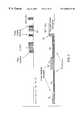
- FIG. 1is a common packet channel system block diagram with a common control downlink channel
- FIG. 2is common packet channel system block diagram with a dedicated downlink channel
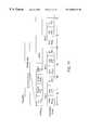
- FIG. 3is a block diagram of a base station receiver and transmitter for common packet channel
- FIG. 4is a block diagram of a remote station receiver and transmitter for common packet channel
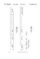
- FIG. 5is a timing diagram for access burst transmission
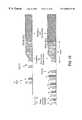
- FIG. 6illustrates common packet channel access burst of FIG. 5 using a common control downlink channel
- FIG. 7illustrates common packet channel access of FIG. 5 using a dedicated downlink channel
- FIG. 8shows the structure of the preamble
- FIG. 9illustrates preamble and pilot formats
- FIG. 10is a common packet channel timing diagram and frame format of the down link common control link
- FIG. 11illustrates frame format of common packet channel, packet data
- FIG. 12illustrates a common-packet channel timing diagram for mutual pre-data transmission power control
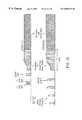
- FIG. 13illustrates a common packet channel timing diagram with associated downlink dedicated physical channel
- FIG. 14illustrates a common packet channel timing diagram with associated downlink physical channel
- FIG. 15illustrates a common packet channel timing diagram with associated downlink physical channel
- FIG. 16illustrates a common packet channel timing diagram with associated downlink dedicated physical channel, with a common preamble for two or more base stations.
- the common-packet channelis a new and novel uplink transport channel for transmitting variable size packets from a mobile station to a base station within listening range, without the need to obtain a two way link with any one or set of base stations.
- the channel resource allocationis contention based; that is, a number of mobile stations could at any time content for the same resources, as found in an ALOHA system.
- common-packet channelprovides an improvement to a code-division-multiple-access (CDMA) system employing spread-spectrum modulation.
- the CDMA systemhas a plurality of base stations (BS) 31 , 32 , 33 and a plurality of remote stations (RS).
- Each remote station 35has an RS-spread-spectrum transmitter and an RS-spread-spectrum receiver.
- An uplinkis from the remote station 35 to a base station 31 .
- the uplinkhas the common-packet channel (CPCH).
- a downlinkis from a base station 31 to the remote station 35 , and is denoted a common-control channel (CCCH).
- the common-control channelhas common signaling used by the plurality of remote stations.
- DPCHdownlink dedicated physical channel
- a BS spread-spectrum transmitter and a BS spread-spectrum receiveris shown.
- the BS spread-spectrum transmitter and the BS spread-spectrum receiverare located at the base station 31 .
- the BS spread-spectrum receiverincludes an antenna 309 coupled to a circulator 310 , a receiver radio frequency (RF) section 311 , a local oscillator 313 , a quadrature demodulator 312 , and an analog-to-digital converter 314 .
- the receiver RF section 311is coupled between the circulator 310 and the quadrature demodulator 312 .
- the quadrature demodulatoris coupled to the local oscillator 313 and to the analog to digital converter 314 .
- the output of the analog-to-digital converter 315is coupled to a programmable-matched filter 315 .
- a preamble processor 316 , pilot processor 317 and data-and-control processor 318are coupled to the programmable-matched filter 315 .
- a controller 319is coupled to the preamble processor 316 , pilot processor 317 and data-and-control processor 318 .
- a de-interleaver 320is coupled between the controller 319 and a forward-error-correction (FEC) decoder 321 .
- FECforward-error-correction
- the BS spread-spectrum transmitterincludes a forward error-correction (FEC) encoder 322 coupled to an interleaver 323 .
- a packet formatter 324is coupled to the interleaver 323 and to the controller 319 .
- a variable gain device 325is coupled between the packet formatter 324 and a product device 326 .
- a spreading-sequence generator 327is coupled to the product device 326 .
- a digital-to-analog converter 328is coupled between the product device 328 and quadrature modulator 329 .
- the quadrature modulator 329is coupled to the local oscillator 313 and a transmitter RF section 330 .
- the transmitter RF section 330is coupled to the circulator 310 .
- the controller 319has control links coupled to the analog-to-digital converter 314 , programmable-matched filter 315 , preamble processor 316 , the digital-to-analog converter 328 , the spreading sequence generator 327 , the variable gain device 325 , the packet formatter 324 , the de-interleaver 320 , the FEC decoder 321 , the interleaver 323 and the FEC encoder 322 .
- a received spread-spectrum signal from antenna 309passes through circulator 310 and is amplified and filtered by receiver RF section 311 .
- the local oscillator 313generates a local signal which quadrature demodulator 312 uses to demodulator in-phase and quadrature phase components of the received spread-spectrum signal.
- the analog-to-digital converter 314converts the in-phase component and the quadrature-phase component to a digital signal.
- the programmable-matched filter 315despreads the received spread-spectrum signal.
- a correlatoras an alternative, may be used as an equivalent means for despreading the received spread-spectrum signal.
- the preamble processor 316detects the preamble portion of the received spread-spectrum signal.
- the pilot processordetects and synchronizes to the pilot portion of the received spread-spectrum signal.
- the data and control processordetects and processes the data portion of the received spread-spectrum signal. Detected data passes through the controller 319 to the de-interleaver 320 and FEC decoder 321 . Data and signaling are outputted from the FEC decoder 321 .
- dataare FEC encoded by FEC encoder 322 , and interleaved by interleaver 323 .
- the packet formatterformats data, signaling, acknowledgment signal, collision detection signal, pilot signal and transmitting power control (TPC) signal into a packet.
- the packetis outputted from packet formatter, and the packet level is amplified or attenuated by variable gain device 325 .
- the packetis spread-spectrum processed by product device 326 , with a spreading chip-sequence from spreading-sequence generator 327 .
- the packetis converted to an analog signal by digital-to-analog converter 328 , and in-phase and quadrature-phase components are generated by quadrature modulator 329 using a signal from local oscillator 313 .
- the packetis translated to a carrier frequency, filtered and amplified by transmitter RF section 330 , and then passes through circulator 310 and is radiated by antenna 309 .
- the RS spread-spectrum transmitter and the RS spread-spectrum receiverare located at the mobile station 35 , shown in FIG. 1 .
- the RS spread-spectrum receiverincludes an antenna 409 coupled to a circulator 410 , a receiver radio frequency (RF) section 411 , a local oscillator 413 , a quadrature demodulator 412 , and an analog-to-digital converter 414 .
- the receiver RF section 411is coupled between the circulator 410 and the quadrature demodulator 412 .
- the quadrature demodulatoris coupled to the local oscillator 413 and to the analog to digital converter 414 .
- the output of the analog-to-digital converter 415is coupled to a programmable-matched filter 415 .
- An acknowledgment detector 416 , pilot processor 417 and data-and-control processor 418are coupled to the programmable-matched filter 415 .
- a controller 419is coupled to the acknowledgment detector 416 , pilot processor 417 and data-and-control processor 418 .
- a de-interleaver 420is coupled between the controller 419 and a forward-error-correction (FEC) decoder 421 .
- FECforward-error-correction
- the RS spread-spectrum transmitterincludes a forward-error-correction (FEC) encoder 422 coupled to an interleaver 423 .
- a packet formatter 424is coupled through a multiplexer 451 to the interleaver 423 and to the controller 419 .
- a preamble generator 452 and a pilot generator 453 for the preambleare coupled to the multiplexer 451 .
- a variable gain device 425is coupled between the packet formatter 424 and a product device 426 .
- a spreading-sequence generator 427is coupled to the product device 426 .
- a digital-to-analog converter 428is coupled between the product device 428 and quadrature modulator 429 .
- the quadrature modulator 429is coupled to the local oscillator 413 and a transmitter RF section 430 .
- the transmitter RF section 430is coupled to the circulator 410 .
- the controller 419has control links coupled to the analog-to-digital converter 414 , programmable-matched filter 415 , acknowledgment detector 416 , the digital-to-analog converter 428 , the spreading sequence generator 427 , the variable gain device 425 , the packet formatter 424 , the de-interleaver 420 , the FEC decoder 421 , the interleaver 423 , the FEC encoder 422 , the preamble generator 452 and the pilot generator 453 .
- a received spread-spectrum signal from antenna 409passes through circulator 410 and is amplified and filtered by receiver RF section 411 .
- the local oscillator 413generates a local signal which quadrature demodulator 412 uses to demodulate in-phase and quadrature phase components of the received spread-spectrum signal.
- the analog-to-digital converter 414converts the in-phase component and the quadrature-phase component to a digital signal.
- the programmable-matched filter 415despreads the received spread-spectrum signal.
- a correlatoras an alternative, may be used as an equivalent means for despreading the received spread-spectrum signal.
- the acknowledgment detector 416detects the an acknowledgment in the received spread-spectrum signal.
- the pilot processordetects and synchronizes to the pilot portion of the received spread-spectrum signal.
- the data and control processordetects and processes the data portion of the received spread-spectrum signal. Detected data passes through the controller 419 to the de-interleaver 420 and FEC decoder 421 . Data and signaling are outputted from the FEC decoder 421 .
- dataare FEC encoded by FEC encoder 422 , and interleaved by interleaver 423 .
- the preamble generator 452generates a preamble and the pilot generator 453 generates a pilot for the preamble.
- the multiplexer 451multiplexes the data, preamble and pilot, and the packet formatter 424 formats the preamble, pilot and data into a common-packet channel packet. Further, the packet formatter formats data, signaling, acknowledgment signal, collision detection signal, pilot signal and TPC signal into a packet.
- the packetis outputted from packet formatter, and the packet level is amplified or attenuated by variable gain device 425 .
- the packetis spread-spectrum processed by product device 426 , with s spreading chip-sequence from spreading-sequence generator 427 .
- the packetis converted to an analog signal by digital-to-analog converter 428 , and in-phase and quadrature-phase components are generated by quadrature modulator 429 using a signal from local oscillator 413 .
- the base stationtransmits a common-synchronization channel, which has a frame time duration T F .
- the common-synchronization channelhas a common chip-sequence signal, which is common to the plurality of remote stations communicating with the particular base station.
- the time T F of one frameis ten milliseconds.
- Within one framethere are eight access slots. Each access slot lasts 1.25 milliseconds.
- Timing for the access slotsis the frame timing, and the portion of the common-synchronization channel with the frame timing is denoted the frame-timing signal.
- the frame-timing signalis the timing a remote station uses in selecting an access slot in which to transmit an access-burst signal.
- a first remote station attempting to access the base stationhas a first RS-spread-spectrum receiver for receiving the common synchronization channel, broadcast from the base station.
- the first RS-spread-spectrum receiverdetermines frame timing from the frame-timing signal.
- a first RS-spread-spectrum transmitterlocated at the first remote station, transmits an access-burst signal.
- An access burst signalstarts at the beginning of an access slot, as defined by the frame timing portion of the common-synchronization channel.
- FIG. 6illustratively shows the common-packet channel access burst format, for each access-burst signal.
- Each access-burst signalhas a plurality of segments.
- Each segmenthas a preamble followed by a pilot signal.
- the plurality of segmentshas a plurality of power levels, respectively. More particularly, the power level of each segment increases with each subsequent segment.
- a first segmenthas a first preamble and pilot, at a first power level P 0 .
- a second segmenthas a second preamble and a second pilot, at a second power level P 1 .
- the third segmenthas a third preamble and a third pilot at a third power level P 2 .
- the first preamble, the second preamble, the third preamble, and subsequent preamblesmay be identical or different.
- the power level of the pilotpreferably is less than the power level of the preamble.
- a preambleis for synchronization, and a corresponding pilot, which follows a preamble, is to keep the BS spread-spectrum receiver receiving the spread-spectrum signal from the remote station, once a preamble is detected.
- a subsequent increase or decrease of power levelsis basically a closed loop power control system.
- the preambleis generated by preamble generator 452 and the pilot is generated by pilot generator 453 .
- a preamble formatis shown in FIG. 8 .
- the preamble format with a pilotis shown in FIG. 9 .
- the multiplexer 451with timing from the controller 419 , selects the preamble then a corresponding pilot, for packet formatter 424 .
- a series of preambles and pilotsmay be generated and made as part of the packet by packet formatter 424 .
- the preambles and pilotscan have their power level adjusted either in the preamble generator 452 and pilot generator 453 , or by the variable gain device 425 .
- the BS spread-spectrum receiverreceives the access-burst signal at a detected-power level. More particularly, the access-burst signal has the plurality of preambles at a plurality of power levels, respectively.
- an acknowledgment (ACK) signalis transmitted from the BS spread-spectrum transmitter.
- the ACK signalis shown in FIG. 6, in response to the fourth preamble having sufficient power for detection by the BS spread-spectrum receiver.
- FIG. 3shows the preamble processor 316 for detecting the preamble and the pilot processor 317 for continuing to receive the packet after detecting the preamble.
- the processor 319Upon detecting the preamble, the processor 319 initiates an ACK signal which passes to packet formatter 324 and is radiated by the BS spread-spectrum transmitter.
- the first RS-spread-spectrum receiverreceives the acknowledgment signal.
- the first RS-spread-spectrum transmittertransmits to the BS-spread-spectrum receiver, a spread-spectrum signal having data.
- the datais shown in FIG. 6, in time, after the ACK signal.
- the dataincludes a collision detection (CD) portion of the signal, referred to herein as a collision detection signal, and message.
- CDcollision detection
- the BS receiverIn response to each packet transmitted from the MS spread-spectrum transmitter, the BS receiver detects the collision detection portion of the data, and retransmits the data field of the collision detection portion of the data to the remote station.
- FIG. 10shows the timing diagram for re-transmitting the collision detection field. There are several slots for collision detection retransmission, which can be used for re-transmitting the collision detection field for several remote stations. If the collision detection field were correctly re-transmitted to the remote station, then the remote station knows its packet is successfully received by the base station. If the collision detection field were not correctly re-transmitted by the base station, then the remote station assumes there is a collision with a packet transmitted by another remote station, and stops further transmission of the data.
- FIG. 11shows a frame format of a common-packet channel data payload.
- a remote stationupon power up searches for transmission from nearby base stations.
- the Remote stationUpon successful synchronization with one or more base stations, the Remote station receives the necessary system parameters from a continuously transmitted by all base stations broadcast control channel (BCCH).
- BCCHbroadcast control channel
- the remote stationcan determine various parameters required when first transmitting to a base station. Parameters of interest are the loading of all the base station in the vicinity of the remote station, their antenna characteristics, spreading codes used to spread the downlink transmitted information, timing information and other control information. With this information, the remote station can transmit specific waveforms in order to capture the attention of a nearby base station.
- the remote stationIn the common packet channel the remote station, having all the necessary information from the nearby base station, it starts transmitting a particular preamble from a set of predefined preambles, at a well selected time intervals.
- the particular structure of the preamble waveformsis selected on the basis that detection of the preamble waveform at the base station is to be as easy as possible with minimal loss in detectability.
- the physical.common packet channel(CPCH) is used to carry the CPCH. It is based on the well known Slotted ALOHA approach. There is a number of well defined time offsets relative to the frame boundary of a downlink received BCCH channel. These time offsets define access slots. The number of access slots is chosen according to the particular application at hand. As an example,shown in FIG. 5, eight access slots are spaced 1.25 msec apart in a frame of 10-msec duration.
- a remote stationpicks an access slot in a random fashion and tries to obtain a connection with a base station by transmitting a preamble waveform.
- the base stationis able to recognize this preamble, and is expecting its reception at the beginning of each access slot.
- the length of the access burstis variable and the length of the access burst is allowed to vary from a few access slots to many frame durations.
- the amount of data transmitted by the remote stationcould depend on various factors. Some of those are: class capability of the remote station, prioritization, the control information transmitted down by the base station, and various bandwidth management protocols residing and executed at the base station.
- a field at the beginning of the data portionsignifies the length of the data.
- the structure of the access burstis shown in FIG. 6 .
- the access burststarts with a set of preambles of duration T P whose power is increased in time from preamble to preamble in a step-wise manner.
- the transmitted power during each preambleis constant.
- the access burstconsists of a pilot signal transmitted at a fixed power level ratio relative to the previously transmitted preamble.
- the pilot signalcould be eliminated by setting it to a zero power level.
- the transmission of the preamblesceases because either the preamble has been picked up, detected, by the base station, and the base station has responded to the remote station with a layer one acknowledgment L 1 ACK which the remote station has also successfully received. Transmission of the preamble ceases also if the remote station has transmitted the maximum allowed number of preambles M P . Upon receiving this L 1 ACK the remote station starts transmission of its data. Once the remote station has transmitted more than M P preambles, it undergoes a forced random back off procedure. This procedure forces the remote station to delay its access burst transmission for a later time. The random back off procedure could be parameterized based on the priority statues of the Remote station.
- the amount by which the power is increased from preamble to preambleis D P which is either fixed for all cells at all times or it is repeatedly broadcast via the BCCH.
- D PThe amount by which the power is increased from preamble to preamble.
- Remote stations with different priorities statuscould use a power increase which depends on a priority status assigned to the remote station.
- the priority statuscould be either predetermined or assigned to the remote station after negotiation with the base station.
- the preferred approachis to use different codes rather than a single repeating code in generating each preamble.
- L possible codesnot necessarily Gold Codes
- a 0 , A 1 , . . . A L ⁇ 1possible preambles will be as shown in FIG. 8 .
- the order of the A i 'scan be chosen so that identical codes are not used in the same locations for two different preambles.
- a similar approachcould be used to form the pilot signals.
- the downlink common control channel structure for even and odd slotsis shown.
- the even slotscontain reference data and control data.
- the pilot symbolsare used to derive a reference for demodulating the remaining control symbols.
- the control symbolsare made of transport frame indicator (TFI) symbols, power control (PC) symbols, collision detection (CD) symbol and signaling symbols (SIG).
- the odd slotscontain all the information that the even slots contain plus an acknowledgment (ACK) signal. Odd slots do not include collision detection fields.
- the uplink CPCHis shown over the last transmitted preamble. After the last transmitted preamble, the base station has successfully detected the transmission of the last transmitted preamble and transmits back the acknowledgment signal. During the same time, the remote station is tuned to receive the ACK signal. The ACK signal transmitted corresponds to the specific preamble structure transmitted on the uplink. Once the remote station detects the ACK signal corresponding to transmitted preamble by the remote station, the remote station begins transmission of its data.
- FIG. 11shows the structure of the uplink frame and the slot format for the data portion of the uplink transmission.
- Data and control informationis transmitted in an in-phase and quadrature-phase multiplexed format. That is, the data portion could be transmitted on the in-phase coordinate and the control portion on the quadrature-phase coordinate.
- the modulation for the data and controlis BPSK.
- the control channelcontains the information for the receiver to enable the demodulation of the data.
- the control channelprovides for upper layer system functionality.
- the data portionconsists of one or more frames. Each frame consists of a number of slots. As an example the frame duration could be 10 milliseconds long and the slot duration 0.625 milliseconds long. In that case, there are 16 slots per frame.
- the beginning of the data payloadcontains a collision detection field used to relay information about the possibility of collision with other simultaneously transmitting remote stations. The collision detection field is read by the base station. The base station expects the presence of the collision detection field since it had provided an ACK signal at the last time slot.
- the collision detection fieldincludes a temporary identification (ID) number chosen at random by the mobile for the transmission of the current packet.
- IDtemporary identification
- the base stationreads the collision detection field and reflects, or transmits back, the collision detection field on the downlink. If the collision detection field detected by the remote station matched the one just being transmitted by the same remote station, then the collision detection field is an identification that the transmission is being received correctly. The remote station then continues transmitting the remaining of the packet. In case the collision detection field has not been received correctly by the remote station, then the remote station considers the packet reception by the base station as erroneous and discontinues transmission of the remaining packet.
- the function of the remaining fieldsare as follows.
- the Pilot fieldenables the demodulation of both the data and control bits.
- the transmitted power control (TPC) bitsare used to control the power of a corresponding downlink channel, in case a down link channel directed to the same user is operational. If the downlink channel were not operational, then the TPC control bits can be used to relay additional pilot bits instead.
- the Rate Information (RI) fieldis used to provide the transmitter with the ability to change its data rate without the necessity to explicitly negotiate the instantaneous data rate with the base station.
- the service fieldprovides information of the particular service the data bits are to be used for.
- the length fieldspecifies the time duration of the packet.
- the signal fieldcan be used to provide additional control information as required.
- Additional functionalities of the common packet channelare: (1) bandwidth management and (2) L 2 acknowledgment mechanism.
- the bandwidth management functionalityis implemented via signaling information on the down link common control channel.
- the firstrelies on changing the priority status of all uplink users, which currently are transmitting information using the CPCH.
- all the usersare remapping their priority status via a control signal sent at the downlink.
- the priority of the CPCH usersis lowered their ability to capture an uplink channel is lowered.
- the other mechanismis for the base station to relay the maximum possible data rate the CPCH users are allowed to transmit.
- the base stationcould provide a negative acknowledgment through the ACK signal. In this case, any remote station which is tuned to receive the ACK signal is prohibited from further transmission of an access-burst signal.
- the L 2 acknowledgment (L 2 ACK) mechanismwhich is different than the L 1 ACK, is used by the base station to notify the remote station for the correctness of an uplink packet reception.
- the base stationcould either relay to the remote station which portions of the packet have being received correctly or which have being received incorrectly.
- the packetcould be identified as consisting of a number of frames, with each frame consisting of a number of sub-frames. The frames are identified by a predetermined number. The sub-frames in each frame are also identified by a specific number.
- One way for the base to relay the information about the correctness of the packetis to identify all the frames and sub-frames that have been received correctly.
- Another wayis to identify the frames and sub-frames that have been received in error.
- the way the base station could identify the correctness of a frame or sub-frameis by checking its cyclic residue code (CRC) field.
- CRCcyclic residue code
- Other more robust mechanisms for acknowledgmentmay be used.
- a negative acknowledgmentmay be part of the common packet channel.
- the base stationcould send a negative acknowledgment (ACK), as part of the L 1 ACK, in order to force the remote station from transmitting the message part.
- ACKnegative acknowledgment
- the base stationtransmits a broadcast common synchronization channel.
- This broadcast common synchronization channelincludes a frame timing signal.
- the remote stationsextract the frame timing transmitted by the base station by receiving the broadcast common synchronization channel.
- the frame timingis used by the remote stations to derive a timing schedule by dividing the frame duration in a number of access slots.
- the remote stationsare allowed to transmit their preambles only at the beginning of each access slot. The actual transmit times for different remote stations could be slightly different due to their different propagation delays.
- Each remote stationrepeatedly transmits its preamble signal until the base station detects the preamble, acknowledges that the preamble is received, and the acknowledgment is correctly received by the remote station. There could be more than one remote station transmitting the same preamble signal in the same access slot. The base station cannot recognize if two or more remote stations were transmitting the same preamble in the same access slot. When the base station detects the transmission of a preamble signal, it transmits back an acknowledgment message. There is one acknowledgment message corresponding to each possible preamble signal. Therefore, the are as many acknowledgment messages as there are preamble signals.
- Each remote stationincludes a collision detection (CD) field in the beginning of the transmitted message.
- the CD fieldis chosen at random by each remote station and independently from each other Remote Station. There is a predefined limited number of CD fields. Two remote stations transmitting their message at the same time most likely chose a different CD field.
- the base stationreceives the CD field, the base station reflects back, transmits back, the CD field to the remote station.
- the remote stationreads the reflected CD field by the base station. If the reflected CD field matched the CD field the remote station transmitted, the remote station assumes that the remote station is being received correctly by the base station and continue transmitting the rest of the message, or data. If the reflected CD field from the base station did not match the one transmitted by the remote station, then the remote station assumes that there has been a collision and stops transmitting the remaining message or data.
- FIG. 12shows an alternative embodiment for the RS-access-burst signal transmitted from the remote station to the base station.
- the base stationtransmits a frame-timing signal using the broadcast common-synchronization channel.
- the remote stationsynchronizes to the broadcast common-synchronization channel and retrieves frame-timing information from the frame-timing signal.
- the frame-timing informationincludes the timing for when the remote station can transmit an access-burst signal.
- the remote stationsets up a transmission timing schedule. For this embodiment, the remote station divides the frame time duration into a number of access-time slots. The duration of a time slot can be half the duration of an access slot.
- the remote stationstarts transmitting an access-burst signal at the beginning of an access-time slot.
- the frame-time reference of the remote stationis not necessarily the same as the frame-time reference of the base station, due to propagation delays.
- the access-burst signal of FIG. 12comprises a plurality of RS-preamble signals, RS-power-control signals, and RS-pilot signals, respectively, transmitted in time, at increasing power levels.
- the power from RS-preamble signal to RS-preamble signalincreases according to the power values P 0 , P 1 , P 2 . . . .
- the power valuesincrease according to their index, that is, P 0 ⁇ P 1 ⁇ P 2 , . . . .
- the combined plurality of RS-preamble signals, RS-power-control signals, and RS-pilot signals,makeup part of, or all of, the access-burst signal.
- the power level of the RS-power-control signal and the RS-pilot signalmay be at a proportion of the power level of the RS-preamble signal.
- the plurality of RS-preamble signals, RS-power-control signals, and RS-pilot signalsis followed in time by a data.
- the access-burst signalalso may include a data part.
- the access-burst signalmay include the plurality of RS-preamble signals, RS-power-control signals, and RS-pilot signals, and the data are considered concatenated to the access-burst signal.
- the datamay include message information, or other information such as signaling, etc.
- the datapreferably are concatenated to, or are part of, the access-burst signal, but may be sent separately from the access-burst signal.
- an RS-power-control signalwhich is a time portion of the access-burst signal, is transmitted first in time during the time interval between RS preamble signal to RS preamble signal.
- the RS-preamble signalis a time portion of the access-burst signal, as shown in FIG. 12 .
- An RS-pilot signalis-transmitted second in time during the time interval between RS-preamble signal to RS-preamble signal.
- the RS-power-control signalis for power control of a dedicated downlink channel.
- the base stationtransmits the dedicated downlink in response to detecting the RS-preamble signal transmitted by the remote station.
- the RS-pilot signalallows the base station to measure the received power from the remote station, and consequently power control the remote station using power control information transmitted from the base station to the remote station.
- the remote stationcontinuously transmits an RS-preamble signal, followed by a RS-power-control signal, and followed by a RS-pilot signal.
- the base station receiversearches for the transmission of the RS-preamble signals.
- the base stationstarts transmitting a BS-preamble signal as shown in FIG. 12 .
- the remote stationafter every transmission of a RS-preamble signal, tunes its receiver to receive the BS-preamble-pilot signal.
- the RS-pilot signal transmission timing offsetis previously known to the remote station.
- the remote stationstarts receiving the BS-preamble-pilot signal at the known time instant.
- the spreading code used by the base station to transmit the BS-preamble-pilot signalis known to the remote station since the BS-preamble-pilot signal is tied to the type of RS-preamble signal which the remote station transmitted.
- the remote stationstarts the reception process of the BS-preamble-pilot signal whether the BS-preamble-pilot signal is transmitted or is not transmitted.
- the remote stationdoes not make an effort to determine if the BS-preamble-pilot signal were transmitted or not.
- the reception of the BS-preamble-pilot signalenables the remote station to measure the signal quality of the transmitted BS-preamble-pilot signal. This quality measure could be, for example, the received signal-to-noise-ratio (SNR), or probability of error, due to the reception of the BS-preamble-pilot signal by the remote station.
- SNRreceived signal-to-noise-ratio
- the initial power level of the BS-preamble-pilot signalis determined by the base station prior to transmission.
- the remote stationdetermines if the SNR of the received BS-preamble-pilot signal were above or below a previously defined SNR level of the remote station (RS-SNR-level). If the BS-preamble-pilot signal were not transmitted by the base station, then the remote station demodulator, or processor, likely decides that the transmitted BS-preamble-pilot signal is received at an SNR well below the previously defined RS-SNR-level.
- the remote stationWhile measuring the received SNR of the BS-preamble-pilot signal, the remote station transmits power control commands using the RS-power-control signal. If the SNR of the received BS-preamble-pilot signal, measured by the remote station, fell below the previously defined RS-SNR-level, then the remote station sends a “increase” signal, e.g., a 1-bit, to the base station; commanding the base station to increase the transmitting power level of the BS-preamble-pilot signal.
- a “increase” signale.g., a 1-bit
- the remote stationsends a “reduce” signal, e.g., a 0-bit, to the base station commanding the base station to reduce the transmission power level of the BS-preamble-pilot signal. This process continues for the time duration of the RS-power-control signal. If the base station had detected the RS-preamble signal, then the power of transmitted BS-preamble-pilot signal is adjusted by the remote station to bring the measured SNR of the received BS-preamble-pilot close to the predefined RS-SNR-level.
- a “reduce” signale.g., a 0-bit
- the base stationAfter a predetermined time interval from detecting of the RS-preamble signal, the base station transmit an acknowledgment message.
- the time of transmission as well as the code structure of the acknowledgment messageis known to the remote station.
- the structure of the acknowledgment messageis tied to the code structure of the RS-preamble transmitted by the remote station.
- the remote stationsets its receiver to detect the acknowledgment message.
- the remote stationstarts transmitting the RS-pilot signal, which the base station is able to receive since the base station knows the transmission time as well as code structure of the RS-pilot signal. If the remote station did not detect an acknowledgment transmitted by the base station, then the remote station assumes that the remote station's previously transmitted RS-preamble signal is not detected by the base station. In such a case, the remote station will set up for transmitting the next RS-preamble signal transmission. If the remote station detected the transmission of the acknowledgment message, then the remote station decodes the message.
- the remote stationdecides if the decoded acknowledgment message is a positive or negative acknowledgment. If the acknowledgment message were determined to be negative, then the remote station stops all transmissions. The remote station starts again at a later time by going to a predetermined back-off process. If the acknowledgment message were determined to be positive, then the remote station continues transmitting the RS-pilot signal.
- the base stationreceives the RS-pilot signal and determines if the received SNR of the received RS-pilot signal were above or below a predetermined BS-SNR-level. If the measured received SNR of the RS-pilot signal were below the predetermined BS-SNR-level, then the base station commands the remote station to increase the transmitting power of the remote station, by sending an “increase” signal, such as a 1-bit command, to the remote station. If the measured received SNR of the RS-pilot signal were above the predetermined BS-SNR-level, then the base station commands the remote station to decrease its transmitting power by sending a “reduce” signal, such as a 0-bit command, to the remote station. These commands could be transmitted via a set of DPCCH-pilot symbols followed by a few power DPCCH-power-control symbols.
- additional power control commandsare transmitted between consecutive DPCCH-power-control symbols and DPCCH-pilot symbols as shown in FIG. 12 .
- the transmission of these power control commandsbrings the power level of the transmitted RS-pilot signal close to the predefined BS-SNR-level.
- the total amount of power change for both the remote station and the base stationmight be limited to a predetermined maximum value. This value could be fixed, or broadcast by the base station. Since the remote station received a positive acknowledgment from the base station and the remote station completed the transmission of the RS-pilot signal, the remote station transmits a RS-collision-detection field followed by a message carrying data information.
- the RS-collision-detection fieldis received by the base station and transmitted back to the remote station at the following transmitted timeslot as a BS-collision-detection field. If the BS-collision-detection field, received by the remote station, matched the RS-collision detection field transmitted by the remote station, then the remote station continues transmitting the remaining message.
- the base stationcontinues to power control the remote station by continuously transmitting DPDCH-pilot signals and DPDCH-power control signals. If the BS-collision-detection field did not match the transmitted RS-collision-detection field, then the remote station decides that its transmission collided with the transmission by another remote station trying to access the base station at the same time using the same RS-access-burst signal code structure and stop any transmission until a later time.
- the mobile stationsearches for a base stations in its immediate neighborhood, and chooses to transmit to the strongest received base station.
- the choice to which base station to transmitis a remote station transmission decision.
- the decisionis based on the power received, or equivalently probability of error, by the remote station from the base stations.
- the remote station transmissionis received by appreciable power from a single base station only. In that case, the remote station needs only to communicate to that base station.
- An estimate of the power at which a base station receives a remote stationcan be generated from the amount of power the remote station receives the base station. This normally is called an open loop power estimate.
- the open loop power estimateallows a remote station to determine the power received at different base stations by the amount of power the remote station receives those base stations. Given that the uplink and downlink frequencies are different, this is not a very accurate estimate.
- the open loop power estimatecan be used to determine if one or more base stations were candidates for communication. This can serve especially well when the remote station is located at the outskirt of a cell. In that case, the remote station's transmission could be received strongly from more than a single base station. A more important measure is the power by which the remote station is being received by the base stations.
- the remote stationchooses a particular base station with which to communicate, and establishes communication with the chosen base station, then, the remote station is linked to that base station.
- RSremote station
- One way the remote station (RS) can choose which base station it should link to,is to transmit a RS-preamble to more than one base station, and then choose either the base station that acknowledges the reception, or to the base station that received the strongest, if more that one base station acknowledged the reception at about the same time.
- the remote stationneeds to transmit alternatively to a number of base stations and also expect their acknowledgments at different times.
- the remote stationtransmits to a single base station and always the same RS-preamble if the remote station deemed that it were in the receiving range of a single only base station.
- the remote stationtransmits sequentially two different preambles to two base stations. These are two RS-preambles.
- the powers of the preamblesincrease in time.
- the preamble for the first base station, base station 0 as indicated by the second subscriptis transmitted at powers P 0,0 , P 1,0 , P 2,0 . . . .
- the preamble for the second base station, base station 1 as indicated by the second subscriptis transmitted at powers P 0,1 , P 1,1 , P 2,1 . . . . In this case, only the first base station acknowledges the reception of second RS-preamble.
- the remote stationthen undergoes through the collision detection/collision resolution (CD/CR) process, the transmission of the RS-CLPC-preamble, and the transmission of the data information.
- Ways to enable preamble transmissions to more than two base stationscan be derived from the above procedure. From FIG. 13, the reception of the last RS-Preamble at the first base station is assumed to be received stronger than the last RS-preamble at the second base station. Therefore, the base station that possessed the better uplink channel is chosen.
- a remote stationcould also have the choice of responding to the first base station that acknowledges a preamble reception. This could be for the case when the information transmission delay needs to be minimized.
- both the first base station and the second base stationacknowledged their corresponding RS-preamble reception.
- the remote stationunderwent the CD/CR process for the first base station without waiting for the reception of the second base station acknowledgment.
- the remaining processis the same as before with the remote station being in link with first base station.
- the remote stationawaits for the possible reception of both acknowledgments before deciding which base station to transmit the CD/CR preamble signal. This allows the remote station to select the base station that is being received the strongest. This does not necessarily guarantee that the base station selected is the one with the better uplink channel. Statistically, however, the base station being received by the remote station the strongest, is the most likely one to have the better uplink channel.
- the remote stationWhen the remote station is in a region at about the same distance from two or more base stations, then the power received at the remote station from the base stations, is not a clear indication of which base station is best receiving the remote station. A mechanism is needed so that the receiving base station is being used for communication most of the time.
- the remote stationcould transmit a RS-preamble that is common to two or more base stations.
- the two or more base stationsform a base-station-group.
- the common RS-preambleis being received by all base stations in the base-station-group.
- the base stations which form the base-station groupis decided by the remote station, using the power readings, or equivalently probability of error readings, from base-station receptions within the receiving-range (RR) of the remote station.
- the remote stationselects the group of base stations that it deems as potential base stations with which to set up a link.
- the information on which base stations belong to in the base-station-group for each remote stationis relayed before hand by a previous communication between the remote station and a base station in the immediate vicinity of the remote station.
- This base stationshould also be a member of the selected base-station-group.
- all base stations in the base-station-groupare tuned to receiving this common RS-preamble.
- one or more base stations from the base-station-groupwill detect the RS-preamble and send over their downlink channel a L 1 Acknowledgment (L 1 ACK).
- two base stations from the base-station-groupacknowledged the common RS-preamble transmission.
- the remote stationknowing the timing of the L 1 acknowledgment for all base stations in the base-station-group, can determine if and how many base stations acknowledged. Measuring the relative powers of the L 1 acknowledgment signals, the remote station then sends a collision detection/collision resolution-preamble (CD/CR-preamble) to a single base station. That is, the remote station sends a CD/CR-preamble which can be detected by the selected base station in the base-station-group. The base station that receives the CD/CR-preamble responds back with the same CD/CR-preamble.
- CD/CR-preamblecollision detection/collision resolution-preamble
- the different CD/CR-preamble code structuresare known to all the base stations in the base-station-group through some negotiation carried out beforehand between the remote station and the base stations in the base-station-group.
- the CD/CR-preambleserves the purpose of detecting the possibility of more than a single common RS-preamble transmission from different remote stations.
- both the remote station and the base stationselected start transmitting closed loop power control preambles (CLPC-preambles).
- CLPC-preamblesclosed loop power control preambles
- the base stationsends a BS-CLPC-preamble and the remote station a RS-CLPC-preamble.
Landscapes
- Engineering & Computer Science (AREA)
- Computer Networks & Wireless Communication (AREA)
- Signal Processing (AREA)
- Mobile Radio Communication Systems (AREA)
- Synchronisation In Digital Transmission Systems (AREA)
Abstract
Description
Claims (49)
Priority Applications (46)
| Application Number | Priority Date | Filing Date | Title |
|---|---|---|---|
| US09/304,345US6606341B1 (en) | 1999-03-22 | 1999-05-04 | Common packet channel with firm handoff |
| APAP/P/2000/001776AAP1451A (en) | 1999-03-22 | 2000-03-14 | Common packet channel. |
| MYPI20001079AMY128734A (en) | 1999-03-22 | 2000-03-20 | Common packet channel |
| PL00350937APL350937A1 (en) | 1999-03-22 | 2000-03-21 | Common packet channel |
| EP00113693AEP1137200A1 (en) | 1999-03-22 | 2000-03-21 | Method for providing a packet communication service in a CDMA wireless network |
| NZ513948ANZ513948A (en) | 1999-03-22 | 2000-03-21 | Common packet channel |
| EP00113694AEP1134912A3 (en) | 1999-03-22 | 2000-03-21 | Method and apparatus for enhanced power ramp-up in a CDMA communication system |
| HU0203207AHUP0203207A2 (en) | 1999-03-22 | 2000-03-21 | Common packet channel |
| AT00940005TATE362244T1 (en) | 1999-03-22 | 2000-03-21 | CHANNEL WITH COMMON PACKAGE |
| DE60034831TDE60034831T2 (en) | 1999-03-22 | 2000-03-21 | Method and base station for transmitting information via a common packet data channel |
| DE60034766TDE60034766T2 (en) | 1999-03-22 | 2000-03-21 | CHANNEL WITH COMMON PACKAGE |
| OA1200000081AOA11361A (en) | 1999-03-22 | 2000-03-21 | Common packet channel. |
| CNB008003815ACN100338890C (en) | 1999-03-22 | 2000-03-21 | Common packet channel |
| AT04007965TATE362245T1 (en) | 1999-03-22 | 2000-03-21 | METHOD AND BASE STATION FOR TRANSMITTING INFORMATION VIA A COMMON PACKET DATA CHANNEL |
| TW089105161ATW567691B (en) | 1999-03-22 | 2000-03-21 | Packet data transfer hardware and method in CDMA system |
| PCT/US2000/007348WO2000057591A1 (en) | 1999-03-22 | 2000-03-21 | Common packet channel |
| EP04007965AEP1443679B1 (en) | 1999-03-22 | 2000-03-21 | Method and base station for transmitting information on a common packet data channel |
| AU39015/00AAU755527B2 (en) | 1999-03-22 | 2000-03-21 | Common packet channel |
| DE60034828TDE60034828T2 (en) | 1999-03-22 | 2000-03-21 | Remote CDMA station and method of data transmission |
| CA002367550ACA2367550C (en) | 1999-03-22 | 2000-03-21 | Common packet channel |
| DZ000050ADZ3024A1 (en) | 1999-03-22 | 2000-03-21 | Common chain for packages. |
| MXPA01009611AMXPA01009611A (en) | 1999-03-22 | 2000-03-21 | Common packet channel. |
| EP00940005AEP1145469B1 (en) | 1999-03-22 | 2000-03-21 | Common packet channel |
| CA2627033ACA2627033C (en) | 1999-03-22 | 2000-03-21 | Common packet channel |
| EP03021404AEP1376898B1 (en) | 1999-03-22 | 2000-03-21 | CDMA remote station and method of transfering data |
| TNTNSN00053ATNSN00053A1 (en) | 1999-03-22 | 2000-03-21 | COMMON PACKAGE CHAIN |
| EA200100981AEA004523B1 (en) | 1999-03-22 | 2000-03-21 | Common packet channel |
| AT03021404TATE362239T1 (en) | 1999-03-22 | 2000-03-21 | REMOTE CDMA STATION AND DATA TRANSMISSION METHOD |
| CZ20013425ACZ20013425A3 (en) | 1999-03-22 | 2000-03-21 | Common packet channel |
| EP00113692AEP1137199A1 (en) | 1999-03-22 | 2000-03-21 | Method of setting up a packet communication in a mobile wireless CDMA system |
| BR0010776-0ABR0010776A (en) | 1999-03-22 | 2000-03-21 | Broad spectrum modulation method, improvement in code division multiple access systems, method for transferring data to a plurality of radio apparatus, method for providing a communication service packet, base station and radio communication system. multiple code division access |
| KR10-2000-0014417AKR100453774B1 (en) | 1999-03-22 | 2000-03-22 | Common packet channel |
| IL13521500AIL135215A0 (en) | 1999-03-22 | 2000-03-22 | Common packet channel |
| ARP000101273AAR023126A1 (en) | 1999-03-22 | 2000-03-22 | METHOD FOR IMPROVING A MULTIPLE ACCESS SYSTEM BY CODE DIVISION (CDMA) THAT EMPLOYS EXPANDED SPECTRUM MODULATION, AN IMPROVEMENT TO SUCH SYSTEM, THE CORRESPONDING METHODS TO TRANSFER DATA AND TO OFFER THE SERVICE AND COMMUNICATION OF SERVICE BASE |
| JP2000079629AJP3515731B2 (en) | 1999-03-22 | 2000-03-22 | Common packet channel |
| JO200022AJO2201B1 (en) | 1999-03-22 | 2000-03-23 | Common packet channel |
| GCP2000574GC0000128A (en) | 1999-03-22 | 2000-03-25 | Common packet channel. |
| MA26334AMA26146A1 (en) | 1999-03-22 | 2001-09-20 | COMMON PACKAGE CHAIN |
| HK02102049.5AHK1042993A1 (en) | 1999-03-22 | 2002-03-18 | Method and apparatus for enhanced power ramp-up in a cdma communication system |
| HK02102322.3AHK1041986A1 (en) | 1999-03-22 | 2002-03-26 | Method of setting up a packet communication in a mobile wireless cdma system |
| US10/607,342US6985511B2 (en) | 1999-03-22 | 2003-06-27 | Common packet channel with firm handoff |
| JP2003334282AJP3880956B2 (en) | 1999-03-22 | 2003-09-25 | Remote station for common packet channel |
| JP2004064827AJP3880973B2 (en) | 1999-03-22 | 2004-03-08 | Common packet channel base station |
| HK04102551.3AHK1061477B (en) | 1999-03-22 | 2004-04-08 | Cdma remote station and method of transfering data |
| KR10-2004-0039883AKR100457144B1 (en) | 1999-03-22 | 2004-06-02 | Common packet channel |
| HK04106884.2AHK1065183B (en) | 1999-03-22 | 2004-09-10 | Method and base station for transmitting information on a common packet data channel |
Applications Claiming Priority (3)
| Application Number | Priority Date | Filing Date | Title |
|---|---|---|---|
| US09/273,508US6169759B1 (en) | 1999-03-22 | 1999-03-22 | Common packet channel |
| US09/275,010US6389056B1 (en) | 1999-03-22 | 1999-03-24 | Pre-data power control common packet channel |
| US09/304,345US6606341B1 (en) | 1999-03-22 | 1999-05-04 | Common packet channel with firm handoff |
Related Parent Applications (2)
| Application Number | Title | Priority Date | Filing Date |
|---|---|---|---|
| US09/273,508Continuation-In-PartUS6169759B1 (en) | 1999-03-22 | 1999-03-22 | Common packet channel |
| US09/275,010Continuation-In-PartUS6389056B1 (en) | 1999-03-22 | 1999-03-24 | Pre-data power control common packet channel |
Related Child Applications (1)
| Application Number | Title | Priority Date | Filing Date |
|---|---|---|---|
| US10/607,342ContinuationUS6985511B2 (en) | 1999-03-22 | 2003-06-27 | Common packet channel with firm handoff |
Publications (1)
| Publication Number | Publication Date |
|---|---|
| US6606341B1true US6606341B1 (en) | 2003-08-12 |
Family
ID=27402579
Family Applications (2)
| Application Number | Title | Priority Date | Filing Date |
|---|---|---|---|
| US09/304,345Expired - LifetimeUS6606341B1 (en) | 1999-03-22 | 1999-05-04 | Common packet channel with firm handoff |
| US10/607,342Expired - Fee RelatedUS6985511B2 (en) | 1999-03-22 | 2003-06-27 | Common packet channel with firm handoff |
Family Applications After (1)
| Application Number | Title | Priority Date | Filing Date |
|---|---|---|---|
| US10/607,342Expired - Fee RelatedUS6985511B2 (en) | 1999-03-22 | 2003-06-27 | Common packet channel with firm handoff |
Country Status (23)
| Country | Link |
|---|---|
| US (2) | US6606341B1 (en) |
| EP (1) | EP1145469B1 (en) |
| JP (3) | JP3515731B2 (en) |
| KR (1) | KR100457144B1 (en) |
| CN (1) | CN100338890C (en) |
| AP (1) | AP1451A (en) |
| AT (3) | ATE362244T1 (en) |
| AU (1) | AU755527B2 (en) |
| BR (1) | BR0010776A (en) |
| CA (1) | CA2367550C (en) |
| CZ (1) | CZ20013425A3 (en) |
| DE (3) | DE60034766T2 (en) |
| DZ (1) | DZ3024A1 (en) |
| EA (1) | EA004523B1 (en) |
| HU (1) | HUP0203207A2 (en) |
| IL (1) | IL135215A0 (en) |
| MA (1) | MA26146A1 (en) |
| MX (1) | MXPA01009611A (en) |
| NZ (1) | NZ513948A (en) |
| OA (1) | OA11361A (en) |
| PL (1) | PL350937A1 (en) |
| TW (1) | TW567691B (en) |
| WO (1) | WO2000057591A1 (en) |
Cited By (33)
| Publication number | Priority date | Publication date | Assignee | Title |
|---|---|---|---|---|
| US20010046220A1 (en)* | 2000-02-17 | 2001-11-29 | Samsung Electronics Co., Ltd. | Apparatus and method for assigning a common packet channel in a CDMA communication system |
| US20020098799A1 (en)* | 2001-01-19 | 2002-07-25 | Struhsaker Paul F. | Apparatus and method for operating a subscriber interface in a fixed wireless system |
| US20020141479A1 (en)* | 2000-10-30 | 2002-10-03 | The Regents Of The University Of California | Receiver-initiated channel-hopping (RICH) method for wireless communication networks |
| US20030048753A1 (en)* | 2001-08-30 | 2003-03-13 | Ahmad Jalali | Method and apparatus for multi-path elimination in a wireless communication system |
| US20030067961A1 (en)* | 2001-10-04 | 2003-04-10 | Hudson John E. | Wireless spread spectrum communications system, communications apparatus and method therefor |
| US20030174672A1 (en)* | 2001-03-17 | 2003-09-18 | Christoph Herrmann | Network with common transmission channels |
| US6804206B1 (en)* | 1999-05-07 | 2004-10-12 | Koninklijke Philips Electronics N.V. | Radio communication system |
| US6907015B1 (en)* | 1999-08-03 | 2005-06-14 | Koninklijke Philips Electronics N.V. | Radio communication system |
| US20050143121A1 (en)* | 2003-12-29 | 2005-06-30 | Samsung Electronics Co., Ltd. | Method and apparatus for adaptive open-loop power control in mobile communication system using TDD |
| US6934268B1 (en)* | 1999-11-26 | 2005-08-23 | Telefonktiebolaget Lm Ericsson | Method for allocating and controlling downlink power in a telecommunication system |
| WO2005029753A3 (en)* | 2003-09-18 | 2006-05-04 | Agile Tv Corp | Method and apparatus for efficient preamble detection in digital data receivers |
| US7061878B2 (en)* | 1999-11-24 | 2006-06-13 | Lg Electronics Inc. | Method and apparatus for stopping data/packet transmission |
| US7068613B1 (en)* | 1999-11-24 | 2006-06-27 | Lg Electronics Inc. | Method and apparatus for stopping data/packet transmission |
| EP1852983A1 (en)* | 2003-12-29 | 2007-11-07 | Samsung Electronics Co., Ltd | Method and apparatus for adaptive open-loop power control in mobile communication system using TDD |
| US20070286129A1 (en)* | 2000-02-02 | 2007-12-13 | Ntt Docomo, Inc | Single carrier/ds-cdma packet transmission method, an uplink packet transmission method in a multi-carrier/ds-cdma mobile communications system, and a structure of a downlink channel in a multi-carrier/ds-cdma mobile communications system |
| US7436801B1 (en) | 2004-09-08 | 2008-10-14 | Golden Bridge Technology, Inc. | Deferred access method for uplink packet channel |
| US20090019113A1 (en)* | 2007-07-10 | 2009-01-15 | Qualcomm Incorporated | Method and apparatus for supporting group communications |
| US20090016317A1 (en)* | 2007-07-10 | 2009-01-15 | Qualcomm Incorporated | Methods and apparatus for supporting group communications utilizing device identifiers |
| US20090019173A1 (en)* | 2007-07-10 | 2009-01-15 | Qualcomm Incorporated | Methods and apparatus for supporting broadcast communications in a peer to peer network |
| US20090016311A1 (en)* | 2007-07-10 | 2009-01-15 | Qualcomm Incorporated | Methods and apparatus for supporting group communications with data re-transmission support |
| WO2009016260A1 (en) | 2007-08-01 | 2009-02-05 | Nokia Siemens Networks Oy | Resource allocation |
| GB2452288A (en)* | 2007-08-29 | 2009-03-04 | Nokia Siemens Networks Oy | Timing of wireless transmissions using a common channel |
| US20090097452A1 (en)* | 2007-10-12 | 2009-04-16 | Qualcomm Incorporated | Femto cell synchronization and pilot search methodology |
| WO2009038359A3 (en)* | 2007-09-21 | 2009-05-14 | Lg Electronics Inc | Method for receiving preamble from other communication system and method for adaptively changing the measurement gap to discover the other communication system |
| US20090161732A1 (en)* | 1999-08-13 | 2009-06-25 | Viasat, Inc. | Method and apparatus for multiple access over a communication channel |
| US7953411B1 (en)* | 2004-06-09 | 2011-05-31 | Zte (Usa) Inc. | Virtual soft hand over in OFDM and OFDMA wireless communication network |
| US20110188558A1 (en)* | 2008-08-11 | 2011-08-04 | Ntt Docomo, Inc. | User apparatus and cell search method |
| US20110228691A1 (en)* | 2007-07-10 | 2011-09-22 | Qualcomm Incorporated | Methods and appartus for controlling interference to broadcast signaling in a peer to peer network |
| USRE42744E1 (en)* | 2000-06-30 | 2011-09-27 | Nokia Corporation | Method of sending feedback information in a fast automatic repeat request forming part of an overall wireless communication system |
| US20120079348A1 (en)* | 2010-09-24 | 2012-03-29 | Helia Naeimi | Data with appended crc and residue value and encoder/decoder for same |
| US20160128014A1 (en)* | 2005-12-09 | 2016-05-05 | Intel Corporation | Frequency correction in a multi-carrier communication system |
| US10244539B2 (en)* | 2014-08-27 | 2019-03-26 | Samsung Electronics Co., Ltd. | Wireless communication system and method for managing resource for interference coordination therein |
| US20190260626A1 (en)* | 2018-02-22 | 2019-08-22 | Electronics And Telecommunications Research Institute | Modem performing modulation or demodulation based on length of burst in data packet, and method performed by the modem |
Families Citing this family (37)
| Publication number | Priority date | Publication date | Assignee | Title |
|---|---|---|---|---|
| US6606341B1 (en) | 1999-03-22 | 2003-08-12 | Golden Bridge Technology, Inc. | Common packet channel with firm handoff |
| KR100467364B1 (en)* | 1999-05-05 | 2005-01-24 | 마쓰시타 덴소 시스템 가부시키가이샤 | ACTIVATION OF MULTIPLE xDSL MODEMS WITH POWER CONTROL MEASUREMENT |
| US6643318B1 (en) | 1999-10-26 | 2003-11-04 | Golden Bridge Technology Incorporated | Hybrid DSMA/CDMA (digital sense multiple access/code division multiple access) method with collision resolution for packet communications |
| US7206580B2 (en)* | 1999-11-04 | 2007-04-17 | Qualcomm Incorporated | Method and apparatus for performing handoff in a high speed communication system |
| US6963540B2 (en) | 1999-11-29 | 2005-11-08 | Samsung Electronics Co., Ltd. | Apparatus and method for assigning a common packet channel in a CDMA communication system |
| US6480525B1 (en) | 1999-11-29 | 2002-11-12 | Golden Bridge Technology Inc. | Second level collision resolution for packet data communications |
| CN101534570A (en)* | 2000-02-23 | 2009-09-16 | Ipr特许公司 | Access probe acknowledgement with collision detection |
| GB0010786D0 (en)* | 2000-05-05 | 2000-06-28 | Roke Manor Research | A high density fast uplink mechanism for statistically multiplexed voice and data |
| US6922389B1 (en) | 2000-11-15 | 2005-07-26 | Qualcomm, Incorporated | Method and apparatus for reducing transmission power in a high data rate system |
| JP2002186014A (en)* | 2000-12-12 | 2002-06-28 | Matsushita Electric Ind Co Ltd | Wireless base station device and communication terminal device |
| US6947748B2 (en)* | 2000-12-15 | 2005-09-20 | Adaptix, Inc. | OFDMA with adaptive subcarrier-cluster configuration and selective loading |
| KR20020055227A (en)* | 2000-12-28 | 2002-07-08 | 박종섭 | Up-link data transmission method using common packet channel in mobile communication system |
| US7684565B2 (en)* | 2001-01-16 | 2010-03-23 | General Instrument Corporation | System for securely communicating information packets |
| JP3736429B2 (en) | 2001-02-21 | 2006-01-18 | 日本電気株式会社 | Cellular system, base station, mobile station, and communication control method |
| JP3583730B2 (en)* | 2001-03-26 | 2004-11-04 | 株式会社東芝 | Wireless communication system and wireless transmission device |
| DE10154428B4 (en) | 2001-08-07 | 2013-04-18 | Siemens Aktiengesellschaft | Methods, devices and software programs for adapting uplink signaling in multicasting |
| US7548506B2 (en)* | 2001-10-17 | 2009-06-16 | Nortel Networks Limited | System access and synchronization methods for MIMO OFDM communications systems and physical layer packet and preamble design |
| TWI431970B (en)* | 2002-02-19 | 2014-03-21 | Interdigital Tech Corp | Method and apparatus for providing a highly reliable ack/nack for time division duplex (tdd) and frequency division duplex (fdd) |
| US7986672B2 (en)* | 2002-02-25 | 2011-07-26 | Qualcomm Incorporated | Method and apparatus for channel quality feedback in a wireless communication |
| US7990883B2 (en)* | 2003-05-16 | 2011-08-02 | Sony Corporation | Communication system, communication method, communication apparatus, communication control method, and computer program |
| US7522677B2 (en)* | 2003-10-21 | 2009-04-21 | Texas Instruments Incorporated | Receiver with low power listen mode in a wireless local area network |
| TWI262694B (en)* | 2004-01-13 | 2006-09-21 | Interdigital Tech Corp | Code division multiple access (CDMA) method and apparatus for protecting and authenticating wirelessly transmitted digital information |
| DE602004011899T2 (en)* | 2004-04-21 | 2009-02-12 | Sony Deutschland Gmbh | Frame synchronization with interference reduction |
| KR100725773B1 (en)* | 2004-08-20 | 2007-06-08 | 삼성전자주식회사 | Apparatus and method for adaptively changing uplink power control scheme according to terminal state in time division duplex mobile communication system |
| JP4619797B2 (en)* | 2005-01-14 | 2011-01-26 | 富士通株式会社 | Wireless communication system and wireless communication device |
| EP1808983A1 (en)* | 2006-01-13 | 2007-07-18 | THOMSON Licensing | Process and devices for selective collision detection |
| KR100913089B1 (en) | 2006-02-07 | 2009-08-21 | 엘지전자 주식회사 | Method for Transmitting Pilot for Multiple Carrier System |
| KR101063509B1 (en) | 2006-06-13 | 2011-09-08 | 콸콤 인코포레이티드 | Power Control for Wireless Communication Systems |
| EP2036285B1 (en)* | 2006-06-30 | 2016-08-24 | ViaSat, Inc. | Remote non-linearity detection via burst power dithering |
| EP2070380B1 (en)* | 2006-10-02 | 2017-06-21 | Optis Wireless Technology, LLC | Method for reducing intra-cell interference between cell phones performing random access |
| KR101365561B1 (en)* | 2006-10-02 | 2014-02-21 | 엘지전자 주식회사 | Method For Effectively Transmitting Synchronization Channel And Method For Allocating Transmission Power For The Same |
| KR100933145B1 (en) | 2006-10-25 | 2009-12-21 | 삼성전자주식회사 | Radio resource allocation method and apparatus using random access procedure in mobile communication system |
| JP5140300B2 (en)* | 2007-03-23 | 2013-02-06 | 株式会社エヌ・ティ・ティ・ドコモ | Mobile station, radio base station, and synchronization establishment method |
| WO2008156034A1 (en)* | 2007-06-18 | 2008-12-24 | Sharp Kabushiki Kaisha | Mobile station, mobile communication system, and communication method |
| JP4376291B2 (en) | 2008-03-21 | 2009-12-02 | 株式会社エヌ・ティ・ティ・ドコモ | Mobile station and base station apparatus |
| US20150365982A1 (en)* | 2014-06-13 | 2015-12-17 | Sony Corporation | Massive mimo link setup |
| CN110859010B (en)* | 2018-08-24 | 2024-04-16 | 华为技术有限公司 | Method and device for realizing conflict detection of data transmission |
Citations (62)
| Publication number | Priority date | Publication date | Assignee | Title |
|---|---|---|---|---|
| US4689786A (en) | 1985-03-21 | 1987-08-25 | Apple Computer, Inc. | Local area network with self assigned address method |
| US5103459A (en) | 1990-06-25 | 1992-04-07 | Qualcomm Incorporated | System and method for generating signal waveforms in a cdma cellular telephone system |
| WO1993018601A1 (en) | 1992-03-05 | 1993-09-16 | Qualcomm Incorporated | Apparatus and method for reducing message collision between mobile stations simultaneously accessing a base station in a cdma cellular communications system |
| US5280472A (en) | 1990-12-07 | 1994-01-18 | Qualcomm Incorporated | CDMA microcellular telephone system and distributed antenna system therefor |
| US5295140A (en) | 1991-03-28 | 1994-03-15 | Motorola, Inc. | Method for multi-purpose utilization of resources in a communication system |
| US5305308A (en) | 1991-07-09 | 1994-04-19 | At&T Bell Laboratories | Wireless access telephone-to-telephone network interface architecture |
| US5329550A (en) | 1990-11-15 | 1994-07-12 | Alcatel Radiotelephone | Signal processing circuit for the European digital cellular radio system |
| US5384777A (en) | 1993-04-19 | 1995-01-24 | International Business Machines Corporation | Adaptive medium access control scheme for wireless LAN |
| US5461639A (en) | 1993-11-22 | 1995-10-24 | Qualcomm Incorporated | Fast forward link power control in a code division multiple access system |
| US5491837A (en) | 1994-03-07 | 1996-02-13 | Ericsson Inc. | Method and system for channel allocation using power control and mobile-assisted handover measurements |
| US5535210A (en) | 1994-07-29 | 1996-07-09 | Motorola, Inc. | Method and system for resolution of channel access in data transmission systems |
| US5537397A (en) | 1994-06-07 | 1996-07-16 | Aloha Networks, Inc. | Spread aloha CDMA data communications |
| EP0731578A2 (en) | 1995-03-02 | 1996-09-11 | Nec Corporation | Packet communication system capable of rapidly confirming receipt of downward packet signals |
| US5581707A (en) | 1994-07-27 | 1996-12-03 | Psc, Inc. | System for wireless collection of data from a plurality of remote data collection units such as portable bar code readers |
| US5600754A (en) | 1992-01-28 | 1997-02-04 | Qualcomm Incorporated | Method and system for the arrangement of vocoder data for the masking of transmission channel induced errors |
| US5621723A (en) | 1994-09-27 | 1997-04-15 | Gte Laboratories Incorporated | Power control in a CDMA network |
| EP0773636A1 (en) | 1995-11-13 | 1997-05-14 | Lucent Technologies Inc. | Resource allocation system for wireless networks |
| WO1997029596A2 (en) | 1996-02-06 | 1997-08-14 | Nokia Telecommunications Oy | A connection establishment method, a subscriber terminal unit and a radio system |
| US5671218A (en) | 1994-04-28 | 1997-09-23 | Lucent Technologies Inc. | Controlling power and access of wireless devices to base stations which use code division multiple access |
| US5673259A (en) | 1995-05-17 | 1997-09-30 | Qualcomm Incorporated | Random access communications channel for data services |
| US5729542A (en) | 1995-06-28 | 1998-03-17 | Motorola, Inc. | Method and apparatus for communication system access |
| GB2318256A (en) | 1996-10-11 | 1998-04-15 | Motorola Inc | Soft handoff in a CDMA communication system |
| US5802046A (en) | 1995-06-05 | 1998-09-01 | Omnipoint Corporation | Efficient time division duplex communication system with interleaved format and timing adjustment control |
| US5802465A (en) | 1993-09-06 | 1998-09-01 | Nokia Mobile Phones Ltd. | Data transmission in a radio telephone network |
| US5809430A (en) | 1994-06-03 | 1998-09-15 | Motorola, Inc. | Method and apparatus for base selection in a communication system |
| US5825835A (en) | 1996-02-23 | 1998-10-20 | L-3 Communications Corporation | Multi-user acquisition procedure for multipoint-to-point synchronous CDMA systems |
| US5841768A (en)* | 1996-06-27 | 1998-11-24 | Interdigital Technology Corporation | Method of controlling initial power ramp-up in CDMA systems by using short codes |
| US5850602A (en) | 1995-08-15 | 1998-12-15 | Tisdale; William R. | Communication protocol for mobile earth terminal communication device used in mobile satellite communication system |
| US5875182A (en) | 1997-01-16 | 1999-02-23 | Lockheed Martin Corporation | Enhanced access burst for random access channels in TDMA mobile satellite system |
| US5893036A (en) | 1997-01-30 | 1999-04-06 | Motorola, Inc. | Transmission power control method |
| US5894472A (en) | 1994-05-10 | 1999-04-13 | Alcatel Alsthom Compagnie Generale D'electricite | Packet access method in a cellular digital radio-communications system |
| US5933777A (en) | 1997-04-24 | 1999-08-03 | Telefonaktiebolaget Lm Ericsson (Publ) | System and method for allocating channel elements in a code division multiple access radio telecommunications network |
| US5943327A (en) | 1995-10-23 | 1999-08-24 | Siemens Aktiengesellschaft | Method and arrangement for transmitting data between a cellularly constructed mobile radiotelephone network and a mobile subscriber station |
| US5953369A (en) | 1996-06-10 | 1999-09-14 | Nec Corporation | DS-CDMA receiver with multi-stage serial interference cancelers using power level information appended to data blocks |
| US5982763A (en) | 1996-07-15 | 1999-11-09 | Nec Corporation | Reception timing detection circuit of CDMA receiver and detection method |
| US5991308A (en) | 1995-08-25 | 1999-11-23 | Terayon Communication Systems, Inc. | Lower overhead method for data transmission using ATM and SCDMA over hybrid fiber coax cable plant |
| US6009089A (en) | 1996-08-20 | 1999-12-28 | Lucent Technologies Inc. | Pilot interference cancellation for a coherent wireless code division multiple access receiver |
| US6011788A (en) | 1997-12-10 | 2000-01-04 | L-3 Communications Corporation | S-CDMA fixed wireless loop system employing subscriber unit/radio base unit super-frame alignment |
| WO2000003499A1 (en) | 1998-07-13 | 2000-01-20 | Samsung Electronics Co., Ltd. | Power control device and method for reverse link common channel in mobile communication system |
| US6026081A (en) | 1996-07-05 | 2000-02-15 | Nec Corporation | Method of controlling power on forward link in a cellular |
| US6028851A (en) | 1997-09-26 | 2000-02-22 | Telefonaktiebolaget L M Ericsson (Publ) | System and method for mobile assisted admission control |
| WO2000008908A2 (en) | 1998-08-17 | 2000-02-24 | Samsung Electronics Co., Ltd. | Device and method for transmitting preamble of access channel in mobile communication system |
| US6031832A (en) | 1996-11-27 | 2000-02-29 | Telefonaktiebolaget L M Ericsson (Publ) | Method and apparatus for improving performance of a packet communications system |
| US6038223A (en) | 1997-10-22 | 2000-03-14 | Telefonaktiebolaget Lm Ericsson (Publ) | Access scheme for packet data in a digital cellular communication system |
| US6038250A (en) | 1997-01-07 | 2000-03-14 | Yozan Inc. | Initial synchronization method and receiver for DS-CDMA inter base station asynchronous cellular system |
| WO2000018172A1 (en) | 1998-09-22 | 2000-03-30 | Qualcomm Incorporated | Method and apparatus for rapid assignment of a traffic channel in digital cellular communication systems |
| WO2000022873A1 (en) | 1998-10-15 | 2000-04-20 | Qualcomm Incorporated | Reservation multiple access |
| US6091757A (en) | 1998-12-03 | 2000-07-18 | Motorola, Inc. | Data transmission within a spread-spectrum communication system |
| US6115390A (en) | 1997-10-14 | 2000-09-05 | Lucent Technologies, Inc. | Bandwidth reservation and collision resolution method for multiple access communication networks where remote hosts send reservation requests to a base station for randomly chosen minislots |
| WO2000057591A1 (en) | 1999-03-22 | 2000-09-28 | Golden Bridge Technology, Inc. | Common packet channel |
| WO2000057663A1 (en) | 1999-03-24 | 2000-09-28 | Qualcomm Incorporated | Reservation multiple access |
| US6141337A (en) | 1996-11-07 | 2000-10-31 | Hitachi, Ltd. | Spread spectrum communication system |
| US6141373A (en) | 1996-11-15 | 2000-10-31 | Omnipoint Corporation | Preamble code structure and detection method and apparatus |
| US6144841A (en) | 1998-03-10 | 2000-11-07 | Nortel Networks Corporation | Method and system for managing forward link power control within a code-division multiple access mobile telephone communication network |
| US6163533A (en)* | 1997-04-30 | 2000-12-19 | Telefonaktiebolaget Lm Ericsson (Publ) | Random access in a mobile telecommunications system |
| US6163708A (en) | 1998-12-31 | 2000-12-19 | Nokia Mobile Phones Limited | Closed-loop power control method |
| US6169759B1 (en) | 1999-03-22 | 2001-01-02 | Golden Bridge Technology | Common packet channel |
| US6292471B1 (en)* | 1997-10-31 | 2001-09-18 | Lucent Technologies Inc. | Power control for mobile wireless communication system |
| US6310868B2 (en)* | 1996-06-20 | 2001-10-30 | Ntt Mobile Communications Network Inc. | Signal transmission method, mobile station device, and base station device for CDMA mobile communication system |
| US6442153B1 (en)* | 1997-10-23 | 2002-08-27 | Telefonaktiebolaget Lm Ericsson (Publ) | Random access in a mobile telecommunications system |
| US6480525B1 (en) | 1999-11-29 | 2002-11-12 | Golden Bridge Technology Inc. | Second level collision resolution for packet data communications |
| US6507601B2 (en) | 2000-02-09 | 2003-01-14 | Golden Bridge Technology | Collision avoidance |
Family Cites Families (1)
| Publication number | Priority date | Publication date | Assignee | Title |
|---|---|---|---|---|
| JP2912884B2 (en) | 1995-12-14 | 1999-06-28 | エヌ・ティ・ティ移動通信網株式会社 | Multi-access method, mobile station and base station in CDMA mobile communication system |
- 1999
- 1999-05-04USUS09/304,345patent/US6606341B1/ennot_activeExpired - Lifetime
- 2000
- 2000-03-14APAPAP/P/2000/001776Apatent/AP1451A/enactive
- 2000-03-21MXMXPA01009611Apatent/MXPA01009611A/enactiveIP Right Grant
- 2000-03-21ATAT00940005Tpatent/ATE362244T1/ennot_activeIP Right Cessation
- 2000-03-21DEDE60034766Tpatent/DE60034766T2/ennot_activeExpired - Lifetime
- 2000-03-21EAEA200100981Apatent/EA004523B1/ennot_activeIP Right Cessation
- 2000-03-21NZNZ513948Apatent/NZ513948A/ennot_activeIP Right Cessation
- 2000-03-21EPEP00940005Apatent/EP1145469B1/ennot_activeExpired - Lifetime
- 2000-03-21BRBR0010776-0Apatent/BR0010776A/ennot_activeApplication Discontinuation
- 2000-03-21OAOA1200000081Apatent/OA11361A/enunknown
- 2000-03-21CNCNB008003815Apatent/CN100338890C/ennot_activeCeased
- 2000-03-21WOPCT/US2000/007348patent/WO2000057591A1/enactiveIP Right Grant
- 2000-03-21CACA002367550Apatent/CA2367550C/ennot_activeExpired - Fee Related
- 2000-03-21DEDE60034831Tpatent/DE60034831T2/ennot_activeExpired - Lifetime
- 2000-03-21ATAT04007965Tpatent/ATE362245T1/ennot_activeIP Right Cessation
- 2000-03-21HUHU0203207Apatent/HUP0203207A2/enunknown
- 2000-03-21TWTW089105161Apatent/TW567691B/ennot_activeIP Right Cessation
- 2000-03-21CZCZ20013425Apatent/CZ20013425A3/enunknown
- 2000-03-21ATAT03021404Tpatent/ATE362239T1/ennot_activeIP Right Cessation
- 2000-03-21AUAU39015/00Apatent/AU755527B2/ennot_activeCeased
- 2000-03-21PLPL00350937Apatent/PL350937A1/ennot_activeApplication Discontinuation
- 2000-03-21DZDZ000050Apatent/DZ3024A1/enactive
- 2000-03-21DEDE60034828Tpatent/DE60034828T2/ennot_activeExpired - Lifetime
- 2000-03-22ILIL13521500Apatent/IL135215A0/ennot_activeIP Right Cessation
- 2000-03-22JPJP2000079629Apatent/JP3515731B2/ennot_activeExpired - Fee Related
- 2001
- 2001-09-20MAMA26334Apatent/MA26146A1/enunknown
- 2003
- 2003-06-27USUS10/607,342patent/US6985511B2/ennot_activeExpired - Fee Related
- 2003-09-25JPJP2003334282Apatent/JP3880956B2/ennot_activeExpired - Fee Related
- 2004
- 2004-03-08JPJP2004064827Apatent/JP3880973B2/ennot_activeExpired - Fee Related
- 2004-06-02KRKR10-2004-0039883Apatent/KR100457144B1/ennot_activeExpired - Fee Related
Patent Citations (68)
| Publication number | Priority date | Publication date | Assignee | Title |
|---|---|---|---|---|
| US4689786A (en) | 1985-03-21 | 1987-08-25 | Apple Computer, Inc. | Local area network with self assigned address method |
| US5103459B1 (en) | 1990-06-25 | 1999-07-06 | Qualcomm Inc | System and method for generating signal waveforms in a cdma cellular telephone system |
| US5103459A (en) | 1990-06-25 | 1992-04-07 | Qualcomm Incorporated | System and method for generating signal waveforms in a cdma cellular telephone system |
| US5329550A (en) | 1990-11-15 | 1994-07-12 | Alcatel Radiotelephone | Signal processing circuit for the European digital cellular radio system |
| US5280472A (en) | 1990-12-07 | 1994-01-18 | Qualcomm Incorporated | CDMA microcellular telephone system and distributed antenna system therefor |
| US5295140A (en) | 1991-03-28 | 1994-03-15 | Motorola, Inc. | Method for multi-purpose utilization of resources in a communication system |
| US5305308A (en) | 1991-07-09 | 1994-04-19 | At&T Bell Laboratories | Wireless access telephone-to-telephone network interface architecture |
| US5600754A (en) | 1992-01-28 | 1997-02-04 | Qualcomm Incorporated | Method and system for the arrangement of vocoder data for the masking of transmission channel induced errors |
| US5544196A (en) | 1992-03-05 | 1996-08-06 | Qualcomm Incorporated | Apparatus and method for reducing message collision between mobile stations simultaneously accessing a base station in a CDMA cellular communications system |
| WO1993018601A1 (en) | 1992-03-05 | 1993-09-16 | Qualcomm Incorporated | Apparatus and method for reducing message collision between mobile stations simultaneously accessing a base station in a cdma cellular communications system |
| US5384777A (en) | 1993-04-19 | 1995-01-24 | International Business Machines Corporation | Adaptive medium access control scheme for wireless LAN |
| US5802465A (en) | 1993-09-06 | 1998-09-01 | Nokia Mobile Phones Ltd. | Data transmission in a radio telephone network |
| US5461639A (en) | 1993-11-22 | 1995-10-24 | Qualcomm Incorporated | Fast forward link power control in a code division multiple access system |
| US5491837A (en) | 1994-03-07 | 1996-02-13 | Ericsson Inc. | Method and system for channel allocation using power control and mobile-assisted handover measurements |
| US5671218A (en) | 1994-04-28 | 1997-09-23 | Lucent Technologies Inc. | Controlling power and access of wireless devices to base stations which use code division multiple access |
| US5894472A (en) | 1994-05-10 | 1999-04-13 | Alcatel Alsthom Compagnie Generale D'electricite | Packet access method in a cellular digital radio-communications system |
| US5809430A (en) | 1994-06-03 | 1998-09-15 | Motorola, Inc. | Method and apparatus for base selection in a communication system |
| US5537397A (en) | 1994-06-07 | 1996-07-16 | Aloha Networks, Inc. | Spread aloha CDMA data communications |
| US5581707A (en) | 1994-07-27 | 1996-12-03 | Psc, Inc. | System for wireless collection of data from a plurality of remote data collection units such as portable bar code readers |
| US5535210A (en) | 1994-07-29 | 1996-07-09 | Motorola, Inc. | Method and system for resolution of channel access in data transmission systems |
| US5621723A (en) | 1994-09-27 | 1997-04-15 | Gte Laboratories Incorporated | Power control in a CDMA network |
| EP0731578A2 (en) | 1995-03-02 | 1996-09-11 | Nec Corporation | Packet communication system capable of rapidly confirming receipt of downward packet signals |
| US5673259A (en) | 1995-05-17 | 1997-09-30 | Qualcomm Incorporated | Random access communications channel for data services |
| US5802046A (en) | 1995-06-05 | 1998-09-01 | Omnipoint Corporation | Efficient time division duplex communication system with interleaved format and timing adjustment control |
| US5729542A (en) | 1995-06-28 | 1998-03-17 | Motorola, Inc. | Method and apparatus for communication system access |
| US5850602A (en) | 1995-08-15 | 1998-12-15 | Tisdale; William R. | Communication protocol for mobile earth terminal communication device used in mobile satellite communication system |
| US5991308A (en) | 1995-08-25 | 1999-11-23 | Terayon Communication Systems, Inc. | Lower overhead method for data transmission using ATM and SCDMA over hybrid fiber coax cable plant |
| US5943327A (en) | 1995-10-23 | 1999-08-24 | Siemens Aktiengesellschaft | Method and arrangement for transmitting data between a cellularly constructed mobile radiotelephone network and a mobile subscriber station |
| EP0773636A1 (en) | 1995-11-13 | 1997-05-14 | Lucent Technologies Inc. | Resource allocation system for wireless networks |
| WO1997029596A2 (en) | 1996-02-06 | 1997-08-14 | Nokia Telecommunications Oy | A connection establishment method, a subscriber terminal unit and a radio system |
| US5825835A (en) | 1996-02-23 | 1998-10-20 | L-3 Communications Corporation | Multi-user acquisition procedure for multipoint-to-point synchronous CDMA systems |
| US5953369A (en) | 1996-06-10 | 1999-09-14 | Nec Corporation | DS-CDMA receiver with multi-stage serial interference cancelers using power level information appended to data blocks |
| US6310868B2 (en)* | 1996-06-20 | 2001-10-30 | Ntt Mobile Communications Network Inc. | Signal transmission method, mobile station device, and base station device for CDMA mobile communication system |
| US5841768A (en)* | 1996-06-27 | 1998-11-24 | Interdigital Technology Corporation | Method of controlling initial power ramp-up in CDMA systems by using short codes |
| US6026081A (en) | 1996-07-05 | 2000-02-15 | Nec Corporation | Method of controlling power on forward link in a cellular |
| US5982763A (en) | 1996-07-15 | 1999-11-09 | Nec Corporation | Reception timing detection circuit of CDMA receiver and detection method |
| US6009089A (en) | 1996-08-20 | 1999-12-28 | Lucent Technologies Inc. | Pilot interference cancellation for a coherent wireless code division multiple access receiver |
| GB2318256A (en) | 1996-10-11 | 1998-04-15 | Motorola Inc | Soft handoff in a CDMA communication system |
| US6141337A (en) | 1996-11-07 | 2000-10-31 | Hitachi, Ltd. | Spread spectrum communication system |
| US6141373A (en) | 1996-11-15 | 2000-10-31 | Omnipoint Corporation | Preamble code structure and detection method and apparatus |
| US6031832A (en) | 1996-11-27 | 2000-02-29 | Telefonaktiebolaget L M Ericsson (Publ) | Method and apparatus for improving performance of a packet communications system |
| US6038250A (en) | 1997-01-07 | 2000-03-14 | Yozan Inc. | Initial synchronization method and receiver for DS-CDMA inter base station asynchronous cellular system |
| US5875182A (en) | 1997-01-16 | 1999-02-23 | Lockheed Martin Corporation | Enhanced access burst for random access channels in TDMA mobile satellite system |
| US5893036A (en) | 1997-01-30 | 1999-04-06 | Motorola, Inc. | Transmission power control method |
| US5933777A (en) | 1997-04-24 | 1999-08-03 | Telefonaktiebolaget Lm Ericsson (Publ) | System and method for allocating channel elements in a code division multiple access radio telecommunications network |
| US6163533A (en)* | 1997-04-30 | 2000-12-19 | Telefonaktiebolaget Lm Ericsson (Publ) | Random access in a mobile telecommunications system |
| US6028851A (en) | 1997-09-26 | 2000-02-22 | Telefonaktiebolaget L M Ericsson (Publ) | System and method for mobile assisted admission control |
| US6115390A (en) | 1997-10-14 | 2000-09-05 | Lucent Technologies, Inc. | Bandwidth reservation and collision resolution method for multiple access communication networks where remote hosts send reservation requests to a base station for randomly chosen minislots |
| US6038223A (en) | 1997-10-22 | 2000-03-14 | Telefonaktiebolaget Lm Ericsson (Publ) | Access scheme for packet data in a digital cellular communication system |
| US6442153B1 (en)* | 1997-10-23 | 2002-08-27 | Telefonaktiebolaget Lm Ericsson (Publ) | Random access in a mobile telecommunications system |
| US6292471B1 (en)* | 1997-10-31 | 2001-09-18 | Lucent Technologies Inc. | Power control for mobile wireless communication system |
| US6011788A (en) | 1997-12-10 | 2000-01-04 | L-3 Communications Corporation | S-CDMA fixed wireless loop system employing subscriber unit/radio base unit super-frame alignment |
| US6144841A (en) | 1998-03-10 | 2000-11-07 | Nortel Networks Corporation | Method and system for managing forward link power control within a code-division multiple access mobile telephone communication network |
| WO2000003499A1 (en) | 1998-07-13 | 2000-01-20 | Samsung Electronics Co., Ltd. | Power control device and method for reverse link common channel in mobile communication system |
| WO2000008908A2 (en) | 1998-08-17 | 2000-02-24 | Samsung Electronics Co., Ltd. | Device and method for transmitting preamble of access channel in mobile communication system |
| US6366779B1 (en) | 1998-09-22 | 2002-04-02 | Qualcomm Incorporated | Method and apparatus for rapid assignment of a traffic channel in digital cellular communication systems |
| WO2000018172A1 (en) | 1998-09-22 | 2000-03-30 | Qualcomm Incorporated | Method and apparatus for rapid assignment of a traffic channel in digital cellular communication systems |
| US6256301B1 (en) | 1998-10-15 | 2001-07-03 | Qualcomm Incorporated | Reservation multiple access |
| WO2000022873A1 (en) | 1998-10-15 | 2000-04-20 | Qualcomm Incorporated | Reservation multiple access |
| US6091757A (en) | 1998-12-03 | 2000-07-18 | Motorola, Inc. | Data transmission within a spread-spectrum communication system |
| US6163708A (en) | 1998-12-31 | 2000-12-19 | Nokia Mobile Phones Limited | Closed-loop power control method |
| US6169759B1 (en) | 1999-03-22 | 2001-01-02 | Golden Bridge Technology | Common packet channel |
| WO2000057591A1 (en) | 1999-03-22 | 2000-09-28 | Golden Bridge Technology, Inc. | Common packet channel |
| US6301286B1 (en) | 1999-03-22 | 2001-10-09 | Golden Bridge Technology, Inc. | Common packet channel |
| US6389056B1 (en) | 1999-03-22 | 2002-05-14 | Golden Bridge Technology, Inc. | Pre-data power control common packet channel |
| WO2000057663A1 (en) | 1999-03-24 | 2000-09-28 | Qualcomm Incorporated | Reservation multiple access |
| US6480525B1 (en) | 1999-11-29 | 2002-11-12 | Golden Bridge Technology Inc. | Second level collision resolution for packet data communications |
| US6507601B2 (en) | 2000-02-09 | 2003-01-14 | Golden Bridge Technology | Collision avoidance |
Non-Patent Citations (10)
| Title |
|---|
| "Start UMTS Services with 3G-GPRS:CPCH FACH," Golden Bridge Technology, Innovations and Technologies, pp. 1-20 (Jun. 27, 2000). |
| Dae-Ki Hong et al., "Pilot to data channel power allocation for PCA-DS/CDMA with interference canceler," 2001, IEEE, pp. 331-333. |
| Dong In Kim et al., "Random Assignment/Transmitter Oriented Code Scheme for Centralized DS/SSMA Packet Radio Networks," IEEE Journal on Selected Area in Communication, vol. 14, No. 8, Oct. 1996, pp. 1560-1568. |
| John S. Thompson et al., "Pilot power allocation for CDMA system with antenna arrays," 2000, IEEE, pp. 424-428. |
| Jongray Na, "Error Performance Analysis of Data Based Fast Channel Estimation for CDMA uplink with Staggered Burst Pilot," 1997, IEEE, pp. 2177-2181. |
| Riaz Esmailzadel et al., "A New Slotted ALOHA Based Random Access Method for CDMA Systems," IEEE, ICUPC 1997, pp. 43-47. |
| Sofiene Affes et al., "Pilot assisted STAR for increasing capacity and caverage on the downlink of wideband CDMA networks," 2001, IEEE, pp. 310-313. |
| The Common Packet Channel Considered the 3rd Generation GPRS, System Engineering of Data Services in UMTS W-CDMA System, Galway, Ireland, Oct. 1-4, 2000. |
| U.S. patent application Ser. No. 09/273,450 filed Mar. 22, 1999. |
| U.S. patent application Ser. No. 09/941,756 filed Aug. 30, 2001. |
Cited By (68)
| Publication number | Priority date | Publication date | Assignee | Title |
|---|---|---|---|---|
| US6804206B1 (en)* | 1999-05-07 | 2004-10-12 | Koninklijke Philips Electronics N.V. | Radio communication system |
| US6907015B1 (en)* | 1999-08-03 | 2005-06-14 | Koninklijke Philips Electronics N.V. | Radio communication system |
| US8218599B2 (en)* | 1999-08-13 | 2012-07-10 | Viasat, Inc. | Method and apparatus for multiple access over a communication channel |
| US8520716B2 (en) | 1999-08-13 | 2013-08-27 | Viasat, Inc. | Method and apparatus for multiple access over a communication channel |
| US20090161732A1 (en)* | 1999-08-13 | 2009-06-25 | Viasat, Inc. | Method and apparatus for multiple access over a communication channel |
| US7061878B2 (en)* | 1999-11-24 | 2006-06-13 | Lg Electronics Inc. | Method and apparatus for stopping data/packet transmission |
| US7068613B1 (en)* | 1999-11-24 | 2006-06-27 | Lg Electronics Inc. | Method and apparatus for stopping data/packet transmission |
| US6934268B1 (en)* | 1999-11-26 | 2005-08-23 | Telefonktiebolaget Lm Ericsson | Method for allocating and controlling downlink power in a telecommunication system |
| US20070286129A1 (en)* | 2000-02-02 | 2007-12-13 | Ntt Docomo, Inc | Single carrier/ds-cdma packet transmission method, an uplink packet transmission method in a multi-carrier/ds-cdma mobile communications system, and a structure of a downlink channel in a multi-carrier/ds-cdma mobile communications system |
| US20010046220A1 (en)* | 2000-02-17 | 2001-11-29 | Samsung Electronics Co., Ltd. | Apparatus and method for assigning a common packet channel in a CDMA communication system |
| US7113496B2 (en)* | 2000-02-17 | 2006-09-26 | Samsung Electronics Co., Ltd. | Apparatus and method for assigning a common packet channel in a CDMA communication system |
| USRE42744E1 (en)* | 2000-06-30 | 2011-09-27 | Nokia Corporation | Method of sending feedback information in a fast automatic repeat request forming part of an overall wireless communication system |
| US7002910B2 (en)* | 2000-10-30 | 2006-02-21 | The Regents Of The University Of California | Receiver-initiated channel-hopping (RICH) method for wireless communication networks |
| US20020141479A1 (en)* | 2000-10-30 | 2002-10-03 | The Regents Of The University Of California | Receiver-initiated channel-hopping (RICH) method for wireless communication networks |
| US20020098799A1 (en)* | 2001-01-19 | 2002-07-25 | Struhsaker Paul F. | Apparatus and method for operating a subscriber interface in a fixed wireless system |
| US10177839B2 (en)* | 2001-03-17 | 2019-01-08 | Koninklijke Philips N.V. | Network with common transmission channels |
| US20030174672A1 (en)* | 2001-03-17 | 2003-09-18 | Christoph Herrmann | Network with common transmission channels |
| US9363833B2 (en)* | 2001-03-17 | 2016-06-07 | Koninklijke Philips N.V. | Network with common transmission channels |
| US20030048753A1 (en)* | 2001-08-30 | 2003-03-13 | Ahmad Jalali | Method and apparatus for multi-path elimination in a wireless communication system |
| US20030067961A1 (en)* | 2001-10-04 | 2003-04-10 | Hudson John E. | Wireless spread spectrum communications system, communications apparatus and method therefor |
| WO2005029753A3 (en)* | 2003-09-18 | 2006-05-04 | Agile Tv Corp | Method and apparatus for efficient preamble detection in digital data receivers |
| US7428273B2 (en) | 2003-09-18 | 2008-09-23 | Promptu Systems Corporation | Method and apparatus for efficient preamble detection in digital data receivers |
| US7570968B2 (en)* | 2003-12-29 | 2009-08-04 | Samsung Electronics Co., Ltd | Method and apparatus for adaptive open-loop power control in mobile communication system using TDD |
| AU2004310057B2 (en)* | 2003-12-29 | 2008-06-12 | Nokia Technologies Oy | Method and apparatus for adaptive open-loop power control in mobile communication system using TDD |
| US20050143121A1 (en)* | 2003-12-29 | 2005-06-30 | Samsung Electronics Co., Ltd. | Method and apparatus for adaptive open-loop power control in mobile communication system using TDD |
| EP1551112A3 (en)* | 2003-12-29 | 2006-10-25 | Samsung Electronics Co., Ltd. | Method and apparatus for adaptive open-loop power control in mobile communication system using TDD |
| EP1852983A1 (en)* | 2003-12-29 | 2007-11-07 | Samsung Electronics Co., Ltd | Method and apparatus for adaptive open-loop power control in mobile communication system using TDD |
| US7738908B2 (en) | 2003-12-29 | 2010-06-15 | Samsung Electronics Co., Ltd | Method and apparatus for adaptive open-loop power control in mobile communication system using TDD |
| US20080130527A1 (en)* | 2003-12-29 | 2008-06-05 | Samsung Electronics Co., Ltd. | Method and apparatus for adaptive open-loop power control in mobile communication system using tdd |
| US7953411B1 (en)* | 2004-06-09 | 2011-05-31 | Zte (Usa) Inc. | Virtual soft hand over in OFDM and OFDMA wireless communication network |
| US7436801B1 (en) | 2004-09-08 | 2008-10-14 | Golden Bridge Technology, Inc. | Deferred access method for uplink packet channel |
| US9198172B2 (en) | 2004-09-08 | 2015-11-24 | Google Inc. | Deferred access method for uplink packet channel |
| US8873478B2 (en) | 2004-09-08 | 2014-10-28 | Google Inc. | Deferred access method for uplink packet channel |
| US7869404B2 (en) | 2004-09-08 | 2011-01-11 | Golden Bridge Technology, Inc. | Deferred access method for uplink packet channel |
| US20110080889A1 (en)* | 2004-09-08 | 2011-04-07 | Golden Bridge Technology, Inc. | Deferred access method for uplink packet channel |
| US20160128014A1 (en)* | 2005-12-09 | 2016-05-05 | Intel Corporation | Frequency correction in a multi-carrier communication system |
| US10681662B2 (en) | 2005-12-09 | 2020-06-09 | Intel Corporation | Frequency correction in a multi-carrier communication system |
| US10045319B2 (en)* | 2005-12-09 | 2018-08-07 | Intel Corporation | Frequency correction in a multi-carrier communication system |
| US20180324734A1 (en)* | 2005-12-09 | 2018-11-08 | Intel Corporation | Frequency correction in a multi-carrier communication system |
| US11363554B2 (en) | 2005-12-09 | 2022-06-14 | Apple Inc. | Frequency correction in a multi-carrier communication system |
| US8724609B2 (en) | 2007-07-10 | 2014-05-13 | Qualcomm Incorporated | Methods and apparatus for controlling interference to broadcast signaling in a peer to peer network |
| US8694662B2 (en) | 2007-07-10 | 2014-04-08 | Qualcomm Incorporated | Method and apparatus for communicating transmission requests to members of a group and/or making group related transmission decisions |
| US20090019113A1 (en)* | 2007-07-10 | 2009-01-15 | Qualcomm Incorporated | Method and apparatus for supporting group communications |
| US20090016317A1 (en)* | 2007-07-10 | 2009-01-15 | Qualcomm Incorporated | Methods and apparatus for supporting group communications utilizing device identifiers |
| US20090019173A1 (en)* | 2007-07-10 | 2009-01-15 | Qualcomm Incorporated | Methods and apparatus for supporting broadcast communications in a peer to peer network |
| US20090016311A1 (en)* | 2007-07-10 | 2009-01-15 | Qualcomm Incorporated | Methods and apparatus for supporting group communications with data re-transmission support |
| US8495232B2 (en) | 2007-07-10 | 2013-07-23 | Qualcomm Incorporated | Methods and apparatus for supporting broadcast communications in a peer to peer network |
| US20110228691A1 (en)* | 2007-07-10 | 2011-09-22 | Qualcomm Incorporated | Methods and appartus for controlling interference to broadcast signaling in a peer to peer network |
| US8861418B2 (en)* | 2007-07-10 | 2014-10-14 | Qualcomm Incorporated | Methods and apparatus for supporting group communications with data re-transmission support |
| WO2009016260A1 (en) | 2007-08-01 | 2009-02-05 | Nokia Siemens Networks Oy | Resource allocation |
| US20100182974A1 (en)* | 2007-08-01 | 2010-07-22 | Nokia Siemens Networks Oy | Resource Allocation |
| US8391223B2 (en) | 2007-08-01 | 2013-03-05 | Nokia Siemens Networks Oy | Resource allocation |
| EP3026976A1 (en) | 2007-08-01 | 2016-06-01 | Nokia Solutions and Networks Oy | Resource allocation |
| GB2452288A (en)* | 2007-08-29 | 2009-03-04 | Nokia Siemens Networks Oy | Timing of wireless transmissions using a common channel |
| US8451757B2 (en) | 2007-09-21 | 2013-05-28 | Lg Electronics, Inc. | Method for receiving preamble from other communication system and method for adaptively changing the measurement gap to discover the other communication system |
| WO2009038359A3 (en)* | 2007-09-21 | 2009-05-14 | Lg Electronics Inc | Method for receiving preamble from other communication system and method for adaptively changing the measurement gap to discover the other communication system |
| US20100208674A1 (en)* | 2007-09-21 | 2010-08-19 | Jin Lee | Method for receiving preamble from other communication system and method for adaptively changing the measurement gap to discover the other communication system |
| KR101349824B1 (en)* | 2007-09-21 | 2014-01-15 | 엘지전자 주식회사 | Method for receiving preamble from other communication system and method for changing adaptively the measurement gap to discover the other communication system |
| US20090097452A1 (en)* | 2007-10-12 | 2009-04-16 | Qualcomm Incorporated | Femto cell synchronization and pilot search methodology |
| CN102172071B (en)* | 2008-08-11 | 2014-09-24 | 株式会社Ntt都科摩 | User equipment and cell search method |
| US20110188558A1 (en)* | 2008-08-11 | 2011-08-04 | Ntt Docomo, Inc. | User apparatus and cell search method |
| US8526555B2 (en)* | 2008-08-11 | 2013-09-03 | Ntt Docomo, Inc. | User apparatus and cell search method |
| CN102172071A (en)* | 2008-08-11 | 2011-08-31 | 株式会社Ntt都科摩 | User device and cell search method |
| US20120079348A1 (en)* | 2010-09-24 | 2012-03-29 | Helia Naeimi | Data with appended crc and residue value and encoder/decoder for same |
| US10244539B2 (en)* | 2014-08-27 | 2019-03-26 | Samsung Electronics Co., Ltd. | Wireless communication system and method for managing resource for interference coordination therein |
| US10966210B2 (en) | 2014-08-27 | 2021-03-30 | Samsung Electronics Co., Ltd. | Wireless communication system and method for managing resource for interference coordination therein |
| US20190260626A1 (en)* | 2018-02-22 | 2019-08-22 | Electronics And Telecommunications Research Institute | Modem performing modulation or demodulation based on length of burst in data packet, and method performed by the modem |
| US10637707B2 (en)* | 2018-02-22 | 2020-04-28 | Electronics And Telecommunications Research Institute | Modem performing modulation or demodulation based on length of burst in data packet, and method performed by the modem |
Also Published As
Similar Documents
| Publication | Publication Date | Title |
|---|---|---|
| US6606341B1 (en) | Common packet channel with firm handoff | |
| US6389056B1 (en) | Pre-data power control common packet channel | |
| US8718150B2 (en) | RACH-ramp-up acknowledgement | |
| EP1443679B1 (en) | Method and base station for transmitting information on a common packet data channel | |
| HK1065183B (en) | Method and base station for transmitting information on a common packet data channel | |
| HK1061477B (en) | Cdma remote station and method of transfering data |
Legal Events
| Date | Code | Title | Description |
|---|---|---|---|
| AS | Assignment | Owner name:GOLDEN BRIDGE TECHNOLOGY, INC, NEW JERSEY Free format text:ASSIGNMENT OF ASSIGNORS INTEREST;ASSIGNORS:KANTERAKIS, EMMANUEL;PARSA, KOUROSH;REEL/FRAME:009971/0541 Effective date:19990518 | |
| STCF | Information on status: patent grant | Free format text:PATENTED CASE | |
| FEPP | Fee payment procedure | Free format text:PAYOR NUMBER ASSIGNED (ORIGINAL EVENT CODE: ASPN); ENTITY STATUS OF PATENT OWNER: LARGE ENTITY | |
| REMI | Maintenance fee reminder mailed | ||
| FPAY | Fee payment | Year of fee payment:4 | |
| SULP | Surcharge for late payment | ||
| REMI | Maintenance fee reminder mailed | ||
| FPAY | Fee payment | Year of fee payment:8 | |
| SULP | Surcharge for late payment | Year of fee payment:7 | |
| AS | Assignment | Owner name:GOOGLE INC., CALIFORNIA Free format text:ASSIGNMENT OF ASSIGNORS INTEREST;ASSIGNOR:GOLDEN BRIDGE TECHNOLOGY;REEL/FRAME:027379/0108 Effective date:20111115 | |
| FPAY | Fee payment | Year of fee payment:12 | |
| AS | Assignment | Owner name:GOOGLE INC., CALIFORNIA Free format text:CORRECTIVE ASSIGNMENT TO CORRECT THE INCORRECT PATENT NO. 6,155,483 PREVIOUSLY RECORDED AT REEL: 027379 FRAME: 0113. ASSIGNOR(S) HEREBY CONFIRMS THE ASSIGNMENT;ASSIGNOR:GOLDEN BRIDGE TECHNOLOGY, INC.;REEL/FRAME:036131/0154 Effective date:20111115 | |
| AS | Assignment | Owner name:GOOGLE INC., CALIFORNIA Free format text:CORRECTIVE ASSIGNMENT TO CORRECT THE ERRONEOULY LISTED PATENT NUMBER 6,156,483 PREVIOUSLY RECORDED AT REEL: 027379 FRAME: 0108. ASSIGNOR(S) HEREBY CONFIRMS THE ASSIGNMENT;ASSIGNOR:GOLDEN BRIDGE TECHNOLOGY, INC.;REEL/FRAME:036170/0457 Effective date:20111115 | |
| AS | Assignment | Owner name:GOOGLE LLC, CALIFORNIA Free format text:CHANGE OF NAME;ASSIGNOR:GOOGLE INC.;REEL/FRAME:044213/0313 Effective date:20170929 |