US6606322B2 - Route lookup caching for a fiber channel switch - Google Patents
Route lookup caching for a fiber channel switchDownload PDFInfo
- Publication number
- US6606322B2 US6606322B2US09/932,534US93253401AUS6606322B2US 6606322 B2US6606322 B2US 6606322B2US 93253401 AUS93253401 AUS 93253401AUS 6606322 B2US6606322 B2US 6606322B2
- Authority
- US
- United States
- Prior art keywords
- port
- route
- fibre channel
- exit port
- cache
- Prior art date
- Legal status (The legal status is an assumption and is not a legal conclusion. Google has not performed a legal analysis and makes no representation as to the accuracy of the status listed.)
- Expired - Lifetime
Links
- 239000000835fiberSubstances0.000titleclaimsabstractdescription84
- 239000004744fabricSubstances0.000claimsdescription35
- 238000000034methodMethods0.000claimsdescription28
- 230000004044responseEffects0.000claimsdescription19
- 230000003287optical effectEffects0.000claimsdescription6
- 230000008878couplingEffects0.000claimsdescription3
- 238000010168coupling processMethods0.000claimsdescription3
- 238000005859coupling reactionMethods0.000claimsdescription3
- 238000013461designMethods0.000abstractdescription3
- 239000000872bufferSubstances0.000description19
- 238000010586diagramMethods0.000description6
- 230000006870functionEffects0.000description5
- 238000012545processingMethods0.000description5
- 230000005540biological transmissionEffects0.000description4
- 230000004048modificationEffects0.000description4
- 238000012986modificationMethods0.000description4
- 238000012546transferMethods0.000description3
- 238000013459approachMethods0.000description2
- 238000004891communicationMethods0.000description2
- 238000013519translationMethods0.000description2
- 239000010754BS 2869 Class FSubstances0.000description1
- 230000004075alterationEffects0.000description1
- 230000000903blocking effectEffects0.000description1
- 230000003139buffering effectEffects0.000description1
- 238000001514detection methodMethods0.000description1
- 230000000694effectsEffects0.000description1
- 238000005516engineering processMethods0.000description1
- 238000009434installationMethods0.000description1
- 238000007726management methodMethods0.000description1
- 239000000203mixtureSubstances0.000description1
- 230000006855networkingEffects0.000description1
- 230000008569processEffects0.000description1
- 230000011664signalingEffects0.000description1
- 238000010200validation analysisMethods0.000description1
- 238000013316zoningMethods0.000description1
Images


Classifications
- H—ELECTRICITY
- H04—ELECTRIC COMMUNICATION TECHNIQUE
- H04L—TRANSMISSION OF DIGITAL INFORMATION, e.g. TELEGRAPHIC COMMUNICATION
- H04L49/00—Packet switching elements
- H04L49/30—Peripheral units, e.g. input or output ports
- H04L49/3009—Header conversion, routing tables or routing tags
- H—ELECTRICITY
- H04—ELECTRIC COMMUNICATION TECHNIQUE
- H04L—TRANSMISSION OF DIGITAL INFORMATION, e.g. TELEGRAPHIC COMMUNICATION
- H04L45/00—Routing or path finding of packets in data switching networks
- H04L45/54—Organization of routing tables
- H—ELECTRICITY
- H04—ELECTRIC COMMUNICATION TECHNIQUE
- H04L—TRANSMISSION OF DIGITAL INFORMATION, e.g. TELEGRAPHIC COMMUNICATION
- H04L45/00—Routing or path finding of packets in data switching networks
- H04L45/60—Router architectures
- H—ELECTRICITY
- H04—ELECTRIC COMMUNICATION TECHNIQUE
- H04L—TRANSMISSION OF DIGITAL INFORMATION, e.g. TELEGRAPHIC COMMUNICATION
- H04L49/00—Packet switching elements
- H04L49/25—Routing or path finding in a switch fabric
- H—ELECTRICITY
- H04—ELECTRIC COMMUNICATION TECHNIQUE
- H04L—TRANSMISSION OF DIGITAL INFORMATION, e.g. TELEGRAPHIC COMMUNICATION
- H04L49/00—Packet switching elements
- H04L49/35—Switches specially adapted for specific applications
- H04L49/356—Switches specially adapted for specific applications for storage area networks
- H04L49/357—Fibre channel switches
Definitions
- the present inventionrelates, in general, to the field of fibre channel switching technology. More particularly, the present invention relates to a route caching scheme for a receive port in a fibre channel switch.
- Fibre Channelis a high performance, serial interconnect standard designed for bi-directional, point-to-point communications between servers, storage systems, workstations, switches, and hubs. It offers a variety of benefits over other link-level protocols, including efficiency and high performance, scalability, simplicity, ease of use and installation, and support for popular high level protocols.
- Fibre channelemploys a topology known as a “fabric” to establish connections between ports.
- a fabricis a network of switches for interconnecting a plurality of devices without restriction as to the manner in which the switch can be arranged.
- a fabriccan include a mixture of point-to-point and arbitrated loop topologies.
- Fibre ChannelIn Fibre Channel, a channel is established between two nodes where the channel's primary task is to transport data from one point to another at high speed with low latency.
- the Fibre channel switchprovides flexible circuit/packet switched topology by establishing multiple simultaneous point-to-point connections. Because these connections are managed by the switches or “fabric elements” rather than the connected end devices or “nodes”, fabric traffic management is greatly simplified from the perspective of the device.
- a module within the switching elementdetermines the appropriate route for incoming frames based upon a particular destination ID value (D_ID) located within the frame header.
- D_IDdestination ID value
- the D_IDidentifies the exit port associated with the incoming frame.
- a route lookup tableprovides the translation from the D_ID to the appropriate exit port.
- the switchdedicates a unique route lookup table to each port. Since such route lookup tables must necessarily be large to accommodate all the possible associations between the incoming frame D_ID's and the corresponding exit ports, this approach requires a significant amount of memory.
- the route caching design of the present inventionprovides a solution to the aforementioned problem, which is vastly superior to anything currently available. It not only provides quick access to recently used D_ID and exit port combinations, but it does so in an extremely efficient manner without requiring any significant design changes and with only a relatively straightforward alteration to existing processes for networking in a fibre channel switching environment.
- the fibre channel fabricis comprised of a first fibre channel switch that has a plurality of fibre channel ports.
- the fibre channel portsare operative for transmitting and receiving a data frame.
- a plurality of data cachesare provided such that at least one data cache is coupled to at least one of the plurality of fibre channel ports.
- An associationis created between an exit port and a destination identification. The association is stored in at least one data cache coupled to at least one of the plurality of fibre channel ports.
- the present inventionprovides a method for storing a data frame route relationship in a fibre channel fabric.
- a cacheis provided that is operatively coupled to a port of a first fibre channel switch.
- Associating an exit port of the fibre channel switch with a destination identificationcreates a data frame route relationship.
- the destination identificationis a field of a data frame and represents an end location for transmitting said data frame. The association is then stored in the data cache.
- the networkcomprises a fibre channel switch having a plurality of fibre channel ports embodied thereon for transmitting and receiving data frames.
- a route control moduleis coupled to one of the fibre channel ports.
- the route control moduleprovides the identity of an exit port in response to a request from the fibre channel port for the exit port.
- the requestcomprises a destination identification.
- the networkalso has a data cache coupled to the route control module. The data cache stores an association between the exit port and the destination identification.
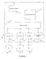
- FIG. 1is a block diagram of a switching element, wherein the switching element has a shared memory, a central route table and a plurality of fibre channel ports;
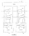
- FIG. 2is a detailed block diagram illustrating one embodiment of an interrelationship between modules of the switching element, particularly the fibre channel ports, local control route module, shared memory, and QC module;
- FIG. 2Ais a block diagram illustrating a typical interface between a fibre channel port and a local route control module
- FIG. 3is a detailed block diagram of a local route control module
- FIG. 4is a flow chart for a data cache operation
- FIG. 5is a block diagram of the request exit port bus and the exit port response bus.
- FIG. 1shows a generalized block diagram of a fibre channel switch for use in a fibre channel fabric implementing the method and systems of the present invention.
- the fibre channel switching element 100 of FIG. 1may be implemented on a single application specific integrated circuit (ASIC).
- ASICapplication specific integrated circuit
- switch 100not shown, such as frame buffer memory could be located in each GL_Port in which case shared memory is replicated with a crossbar switch.
- the fibre channel fabric associated with switch 100is the method for connecting the various N-Ports of the devices together.
- the fabricis capable of routing fibre channel frames using only the destination identification information in the fibre channel frame header.
- the destination identification informationidentifies which N-Port receives the frame.
- Fibre channel switch 100has a plurality of ports for receiving and transferring data through the switch.
- the portsare illustrated as GL-ports 130 , 135 and 140 .
- switch 100comprises 24 GL_Port modules. Each GL_Port is coupled to shared memory 120 and external optical interface 160 . External optical interface couples switch 100 to the N-Port, NL-Port or E-Port of the device coupled to the fibre channel fabric.
- Fibre channel switch 100is associated with a central route table 110 . Central route table 110 is operatively coupled to each GL-Port associated with fibre channel switch 100 (not shown in FIG. 1 ).
- Switch 100also has a system interface 150 .
- System interface module 150provides interfaces to the power supply, fans, temperature sensor, LED's, and the serial interfaces of the optical transceivers.
- fibre channel switch 100has an embedded port 145 in addition to illustrated GL_Ports 130 , 135 and 140 .
- embedded port 145may be used for several functions. First, it may provide a system services processor an access point for all of the fibre channel well-known addresses for both the reception and transmission of frames. Secondly, it may handle any fibre channel frame that cannot be delivered to a destination for either busy, reject, or timeout conditions. It may also be responsible for the generation, modification and/or interpretation of all Fibre Channel-Arbitrated Loop (FC-AL) initialization frames (such as LIFA, LIPA, LIHA, and LISA frames) for the GL-Ports operating in fabric loop mode.
- FC-ALFibre Channel-Arbitrated Loop
- the embedded port interfaceis slightly different than that of an actual GL_Port module. Since the Fibre Channel-0/1 layers are not required, embedded port 145 does not implement the low-level interface for either primitive signaling or sequences. After the system services processor has completed initialization of embedded port 145 , it enters and remains
- Embedded port 145provides a register set accessible to the system services processor for basic initialization and low level control. Once enabled, embedded port 145 is responsible for all functions related to the transmission and reception of frames to and from shared memory 120 . For data path consistency within the following description, the direction of fibre channel frame flow is referenced to shared memory 120 . Thus, a transmit (TX) path actually contains paths destined to, or received by, the embedded port from shared memory 120 and a receive (RX) path contains frames generated or transmitted by embedded port 145 .
- TXtransmit
- RXreceive
- Embedded port 145creates and consumes buffers that contain complete fibre channel frames. Frames may be held in SRAM coupled to embedded port 145 . SRAM will typically hold two frames, one TX frame received from shared memory 120 and one RX frame waiting to be moved into shared memory 120 . All other TX frames waiting to be read by embedded port 145 and RX frames previously created by embedded port 145 are stored in shared memory buffers. In one embodiment, embedded port 145 may be allocated up to 12 shared memory buffers for storage of RX frames. Typically, TX frames utilize the shared memory buffers allocated to the GL-Ports that receive the fibre channel frames.
- a TX framemay be modified in place in the embedded port SRAM by software and sent via an RX path without the need to move the frame.
- One of the shared memory buffers allocated to an embedded portmay be designated as a protected buffer.
- the protected buffercan be filled with an RX frame that is transmitted frequently and left intact so that the frame can be sent to an exit port without the time delay of moving the frame from the extended port SRAM to the shared memory buffer.
- An embedded port receiver(RX) is used to transfer frames from a system services processor to other ports in the switch 100 .
- the Receiver modulewill be identical to the GL_Port RX module described hereinafter.
- an embedded port transmitter(TX) is used to transfer frames from other ports via shared memory to a system services processor.
- the Transmitter modulewill be identical to the GL_Port TX module also described hereinafter.
- An Embedded Port Front Endis used to transfer data between the Embedded Port SRAM and the TX and RX modules.
- Shared memory 120provides buffering and switching for all fibre channel frames that flow through switch 100 . Received frames are written to shared memory 120 by the receiving port then read from shared memory 120 by the transmitting port.
- shared memory 120has 162 total frame locations shared by the GL-Ports 130 , 135 and 140 and embedded port 145 . In such an example, each port may be allocated as many as 12 buffers, so long as the total of 162 buffers is not exceeded.
- Central Route Control module 110provides a common route table for all ports in switch 100 .
- Route tableprovides a translation from each possible Destination ID (D_ID) value to the appropriate exit port. Additionally, the route table provides for hard zoning, which is the capability for blocking traffic from certain receive ports to certain D_IDs. Each port uses an exit port request and response bus to communicate with central route table 110 .
- GL_Ports 130 , 135 and 140transmit and receive fibre channel frames to and from the switch and to and from the fibre channel fabric. As shown in FIG. 1, each GL_Port is coupled to an external optical interface 160 that in turn couples the port to the fabric and ultimately to the N_Port of the destination device.
- GL_Portsmay function as an E_Port, an F_Port or an FL_Port, to name a few.
- An E_Portis an expansion port that serves as a physical interface within the fabric that is used to create multi-switch fabrics by attaching another switches E_Port through an interswitch link (ISL).
- An F_Portis a fabric port that operates as a physical interface within the fabric that attaches to an N_Port of a destination device through a point-to-point link connection.
- An FL_Portis a fabric loop port that contains arbitrated loop (AL) functions associated with the FC-AL topology.
- FC-ALis a fibre channel topology where ports use arbitration to establish a point-to-point circuit.
- FIG. 2illustrates one possible method of connecting GL_Ports 130 and 135 , as well as possible connections between the ports and shared memory 120 and local control route module 200 .
- GL_Port 130has a TX module 230 and an RX module 220 for sending and receiving frames.
- GL_Port 135also has a TX module 235 and RX module 225 . For example, if GL_Port 130 is the receiving port for a data frame and GL_Port 135 is the exit port for the data frame, the frame would first be sent from RX module 220 to shared memory 120 and then sent from shared memory 120 to TX module 235 as illustrated.
- RX port module of GL_Port 130is coupled to TX port module of GL_Port 135 through a QC module 205 .
- QC Control Module 205acts as the control interface between the TX module 235 and RX module 220 .
- QC Control Module 205routes both a request and an acknowledgement signals between GL_Ports that serve to transmit exit port information and location of the fibre channel frame in shared memory from RX module 220 as well as return a successful frame transmission message from TX module 235 .
- LR 200is used by the GL_Port RX module to request the exit port for a frame based on the frame's destination ID value (D_ID).
- D_IDdestination ID value
- a send and receive connectioncouples RX module 220 of GL_Port 130 with LR 200 .
- the connectionallows RX module 220 to request an exit port from the local control route module 200 and also for LR 200 to transmit the identity of the exit port back to RX module 220 .
- FIG. 2Aillustrates the communication between GL_Port 130 and local route control module 200 in greater detail.
- TX control module 230 and RX control module 220are coupled through fibre channel front end module 210 .
- Fibre channel front end (FE) 210provides the FC-0/1 level processing requirements.
- FE 210includes all of the character level state machines required to support a fibre channel link, including all of the requirements for normal data frame processing.
- FE 210provides an interface to the system services processor for low level control over the fibre channel link interface.
- FE 210For the processing of frame traffic, FE 210 provides independent, symmetrical RX and TX interfaces to carry frame data. These paths consist of a data bus and control signals that identify the beginning and ending frame delimiters. For the RX path, status information about the frame including CRC validation, truncated frames and other pertinent status is also included as part of the signal.
- Fibre channel front end 210continuously monitors its receive link for the detection of a start of file (SOF) delimiter in the fibre channel frame. When an SOF is detected, FE 210 then forwards the frame to the RX module 220 . RX module 220 stores the frame into the next available shared memory buffer. RX module 220 uses LR 200 to make a destination port routing decision from the header information of the received frame. RX module 220 then combines the shared memory buffer number into a field, which may be referred to as a Qentry field, which is passed to a TX module of the destination port through QC Module 205 . RX module 220 then waits for the TX module to return the buffer number via an AckQEntry field. When RX module 220 receives the AckQEntry field it indicates to FE 210 that the buffer is being consumed.
- SOFstart of file
- the time that is required for all this processingis less than 1 microsecond. For this example it is most likely that RX module 220 is still storing the received frame while the TX module is transmitting the same frame, creating a cut-through switching effect. If the TX did not immediately transmit the frame, it is possible that the entire frame has been written into the buffer memory when transmission commenced, providing for a store and forward type of switching function.
- the TX logiccontinuously monitors the bus coupling QC Controller 205 with TX module 230 for QEntries. When a QEntry is received, it is placed in TX module 230 . When FE 210 is able to transmit a new frame, the queue selects a QEntry for processing. The shared memory buffer number for the frame to transmit is extracted from the QEntry and the TX module initiates a shared memory read operation. The frame data is then passed from the shared memory 120 to the FE 210 . FE 210 transmits the frame.
- RX module 220 of port 130is coupled to LR module 200 so as to request and receive exit port information.
- RX module 220requests the identity of an exit port for a particular frame by sending a request over ReqExitPort connection 240 to LR 200 .
- LR module 200performs the necessary procedure for retrieving the exit port identity based on the transmitted D_ID.
- LR module 200then transmits the generated exit port information to RX module 220 over ExitPort connection 250 .
- FIGS. 3 and 4illustrate the operation of local route control module 200 in greater detail.
- Local route control module 200is used by GL_Port RX module 220 to request an exit port for a fibre channel frame based on the frame's destination ID value (D_ID).
- D_IDdestination ID value
- the request for an exit portcomes in on the ReqExitPort bus 240 to local route control 200 .
- RX modulerequests an exit port by providing a D_ID from the frame header to local route control module 200 (step 400 ).
- the D_IDhas 24 bits, starting with the 0 bit, which is represented by a designation [23:0].
- the first operation 320 of local route control module 200is to determine if the D_ID identifies a multicast (MC), a broadcast (BC) or a well known address (WKA) (step 410 ). Multicast and broadcast addresses are directed to a MC/BC/WKA table 310 to identify the exit port.
- Well-Known Addresses and FC-AL Loop Initialization addressesalways result in the Embedded Port being selected as the Exit Port. Domain controller identifier addresses are sent to the central route table for exit port lookup unless a bit is set and the frame is not a class F frame, in which case the Embedded port is selected as the exit port.
- central route table 110If central route table 110 has not yet been initialized, then all frames are routed to the embedded port. All other D_ID values are forwarded to central route table 110 . However, prior to forwarding a request for an exit port to central route table 110 , LR 200 performs an operation 330 to determine whether an association between the requested D_ID and an exit port designation is found in route cache 300 (step 430 ). If the D_ID to exit port association is found in route cache 300 , the exit port is available immediately. Route cache 300 improves latency by caching the most recent exit port lookups. In one embodiment, the sixteen most recent lookups are stored in cache 300 . Cache 300 should be cleared when either the central route table 110 or indirect exit port table 350 is modified.
- D_IDis not located in route cache 300 , then local route controller 200 performs an operation 340 to send the D_ID to a central route table 110 .
- Central route table 110retrieves the D_ID to exit port association and returns it to local route controller 200 .
- the D_ID to exit port associationis stored in an indirect exit port table 350 (step 470 ).
- D_ID to exit port associationis stored in route cache 300 .
- D_ID to exit port associationis sent to RX module over ExitPort bus 250 (step 490 ).
- Route cache 300stores information received from central route lookup table 110 , more particularly the most recent exit port lookups performed by local route controller 200 .
- the associationsare stored in flip-flops.
- random access memory, content addressable memory or the likemay be used without departing from the intended scope of the invention.
- Several algorithmsmay be used to store and remove associations in cache 300 . In one embodiment, a least recently used algorithm may be utilized. In another embodiment, a least frequently used algorithm may be utilized.
- Indirect exit port table 350provides the capability for different RX Ports to send frames destined for the same D_ID out different TX Ports. This is useful when two or more inter-element links connect two switches together. Load balancing across inter-element links can be performed without modifying central route table 110 and affecting other ports. Indirect exit port table 350 may be embodied in flip-flops or random access memory to name a few.
- FIG. 5illustrates the structure of a request exit port bus ring structure.
- the request exit port busis used by the receive controller of a GL_Port to request an exit port number for a given D_ID from the central route controller.
- the request exit port busis designed to operate in a ring structure in which each module that is attached to the request exit port bus pipelines and re-powers the request exit port bus signals before sending them to the next module in the ring.
- the local route control moduleis used to provide the attachment to the request exit port bus for each module.
- the request exit port bus signalsare described in Table 1.
- xx_yy_reqep_v 1Valid bit. Set to ‘1’ for 1 period when xx_yy_reqep_* signals are valid. A module may insert its request for an exit port on the bus when it detects that this bit is ‘0’, indicating an empty time slot.
- xx_yy_reqep_rxport 5Receive Port Number. Indicates which receiver port is requesting an exit port.
- xx_yy_reqep_d_id24 Frame destination ID field (D_ID).
- xx_yy_reqep_bid 2 Buffer IdentifierUsed to guarantee in-order delivery of exit port information.
- xx_yy_reqep_p 1 Odd ParityA parity error is reported as a rare event and the request is disgarded.
- FIG. 5also illustrates the exit port response bus ring.
- the exit port response busis used by the central route controller to return an exit port number to an RX module of a GL_Port.
- the exit port response busis designed to operate in a ring structure in which each module that is attached to the exit port response bus pipelines and re-powers the exit port response bus signals before sending them to the next module in the ring.
- the central route controllermay insert an exit port response on the bus in any clock cycle.
- a local route control modulewill extract the exit port response from the bus if it is addressed to that GL_Port.
- the local route control moduleis used to provide the attachment to the exit port response bus for each module.
- the exit port response bus signalsare described in Table 2.
- xx_yy_ep_indirect 1 Indirect Lookup Required BitWhen set to ‘1’ the Indirect Lookup Table, addressed by xx_yy_ep_txport [3:0], must be used for determining the exit port.
- xx_yy_ep_txport 5Transmit Port. Identifies the exit port to which a frame must be sent.
- xx_yy_ep_txport [3:0]addressed the Indirect Lookup Table when the indirect bit is set to ‘1’.
- xx_yy_ep_bid 2 Buffer IdentifierUsed to guarantee in-order delivery of exit port information.
- xx_yy_ep_p 1 Odd ParityA parity error is reported as a rare event and the exit port information is disgarded.
Landscapes
- Engineering & Computer Science (AREA)
- Computer Networks & Wireless Communication (AREA)
- Signal Processing (AREA)
- Data Exchanges In Wide-Area Networks (AREA)
Abstract
Description
| TABLE 1 |
| Request Exit Port Bus Signal Descriptors |
| Signal | Description | |
| xx_yy_reqep_v |
| 1 | Valid bit. Set to ‘1’ for 1 period | |
| when xx_yy_reqep_* signals are | ||
| valid. A module may insert its | ||
| request for an exit port on the bus | ||
| when it detects that this bit is | ||
| ‘0’, indicating an empty time slot. | ||
| xx_yy_reqep_rxport | 5 | Receive Port Number. Indicates |
| which receiver port is requesting an | ||
| exit port. | ||
| xx_yy_reqep_d_id | 24 | Frame destination ID field (D_ID). |
| 2 | Buffer Identifier. Used to | |
| guarantee in-order delivery of exit | ||
| port information. | ||
| 1 | Odd Parity. A parity error is | |
| reported as a rare event and the | ||
| request is disgarded. | ||
| TABLE 2 |
| Exit Port Response Bus Signal Descriptors |
| Signal | Description | |
| xx_yy_ep_v | ||
| 1 | Valid bit. Set to ‘1’ for 1 period | |
| when all xx_yy_ep_* signals are | ||
| valid. Always set to ‘1’ by the | ||
| central route control module. | ||
| Cleared to ‘0’ by the GL_Port, | ||
| addressed by xx_yy_ep_rxport, that | ||
| receives the exit port information. | ||
| 2 | Error Status. 00: OK, 01: Parity Err, | |
| 10: Bad D_ID, 11: Zone Blocked. | ||
| xx_yy_ep_rxport | 5 | Receive Port Number. Indicates |
| which receive port that the exit | ||
| port information is destined for. | ||
| 1 | Indirect Lookup Required Bit. When | |
| set to ‘1’ the Indirect Lookup | ||
| Table, addressed by | ||
| xx_yy_ep_txport [3:0], must be used | ||
| for determining the exit port. | ||
| xx_yy_ep_txport | 5 | Transmit Port. Identifies the exit |
| port to which a frame must be sent. | ||
| xx_yy_ep_txport [3:0] addressed the | ||
| Indirect Lookup Table when the | ||
| indirect bit is set to ‘1’. | ||
| xx_yy_ep_bid | 2 | Buffer Identifier. Used to |
| guarantee in-order delivery of exit | ||
| port information. | ||
| 1 | Odd Parity. A parity error is | |
| reported as a rare event and the | ||
| exit port information is disgarded. | ||
Claims (28)
Priority Applications (3)
| Application Number | Priority Date | Filing Date | Title |
|---|---|---|---|
| US09/932,534US6606322B2 (en) | 2001-08-17 | 2001-08-17 | Route lookup caching for a fiber channel switch |
| PCT/US2002/006229WO2003017583A1 (en) | 2001-08-17 | 2002-02-27 | Route lookup caching for a fibre channel switch |
| EP02707932AEP1423939A4 (en) | 2001-08-17 | 2002-02-27 | Route lookup caching for a fibre channel switch |
Applications Claiming Priority (1)
| Application Number | Priority Date | Filing Date | Title |
|---|---|---|---|
| US09/932,534US6606322B2 (en) | 2001-08-17 | 2001-08-17 | Route lookup caching for a fiber channel switch |
Publications (2)
| Publication Number | Publication Date |
|---|---|
| US20030043816A1 US20030043816A1 (en) | 2003-03-06 |
| US6606322B2true US6606322B2 (en) | 2003-08-12 |
Family
ID=25462465
Family Applications (1)
| Application Number | Title | Priority Date | Filing Date |
|---|---|---|---|
| US09/932,534Expired - LifetimeUS6606322B2 (en) | 2001-08-17 | 2001-08-17 | Route lookup caching for a fiber channel switch |
Country Status (3)
| Country | Link |
|---|---|
| US (1) | US6606322B2 (en) |
| EP (1) | EP1423939A4 (en) |
| WO (1) | WO2003017583A1 (en) |
Cited By (8)
| Publication number | Priority date | Publication date | Assignee | Title |
|---|---|---|---|---|
| US20020034187A1 (en)* | 2000-09-20 | 2002-03-21 | Broadcom Corporation | Network switch having port blocking capability |
| US20030043834A1 (en)* | 2001-08-17 | 2003-03-06 | Mitchem William J. | Compact, shared route lookup table for a fibre channel switch |
| US20030091062A1 (en)* | 2001-11-13 | 2003-05-15 | Lay Samuel C. | Method and apparatus for providing optimized high speed link utilization |
| US20050125424A1 (en)* | 2003-12-05 | 2005-06-09 | Guy Herriott | Decision cache using multi-key lookup |
| US20060034192A1 (en)* | 2004-08-12 | 2006-02-16 | Broadcom Corporation | Apparatus and system for coupling and decoupling initiator devices to a network using an arbitrated loop without disrupting the network |
| US20060133792A1 (en)* | 2004-11-30 | 2006-06-22 | Masataka Ide | Focus detection apparatus and control method thereof |
| US20070005850A1 (en)* | 2005-06-29 | 2007-01-04 | Intel Corporation | Port multiplier mapping apparatus, systems, and methods |
| US7864758B1 (en)* | 2001-09-28 | 2011-01-04 | Emc Corporation | Virtualization in a storage system |
Families Citing this family (9)
| Publication number | Priority date | Publication date | Assignee | Title |
|---|---|---|---|---|
| US7072298B2 (en) | 2001-06-13 | 2006-07-04 | Computer Network Technology Corporation | Method and apparatus for rendering a cell-based switch useful for frame based protocols |
| US7218636B2 (en) | 2001-06-13 | 2007-05-15 | Inrange Technology Corporation | Method and apparatus for rendering a cell-based switch useful for frame based application protocols |
| US7042842B2 (en) | 2001-06-13 | 2006-05-09 | Computer Network Technology Corporation | Fiber channel switch |
| US7260104B2 (en) | 2001-12-19 | 2007-08-21 | Computer Network Technology Corporation | Deferred queuing in a buffered switch |
| US7623519B2 (en) | 2004-06-21 | 2009-11-24 | Brocade Communication Systems, Inc. | Rule based routing in a switch |
| US8396061B2 (en)* | 2004-08-12 | 2013-03-12 | Broadcom Corporation | Apparatus and system for coupling and decoupling initiator devices to a network without disrupting the network |
| US9537793B2 (en)* | 2012-10-10 | 2017-01-03 | Cisco Technology, Inc. | Ensuring any-to-any reachability with opportunistic layer 3 forwarding in massive scale data center environments |
| CN106034266B (en)* | 2015-03-20 | 2020-08-04 | 南京中兴软件有限责任公司 | Optical route generation method and device |
| US10034407B2 (en)* | 2016-07-22 | 2018-07-24 | Intel Corporation | Storage sled for a data center |
Citations (9)
| Publication number | Priority date | Publication date | Assignee | Title |
|---|---|---|---|---|
| US5488608A (en)* | 1994-04-14 | 1996-01-30 | Metricom, Inc. | Method and system for routing packets in a packet communication network using locally constructed routing tables |
| US5491693A (en) | 1993-12-30 | 1996-02-13 | International Business Machines Corporation | General transport layer gateway for heterogeneous networks |
| US5740175A (en)* | 1995-10-03 | 1998-04-14 | National Semiconductor Corporation | Forwarding database cache for integrated switch controller |
| US5991299A (en)* | 1997-09-11 | 1999-11-23 | 3Com Corporation | High speed header translation processing |
| US6032190A (en) | 1997-10-03 | 2000-02-29 | Ascend Communications, Inc. | System and method for processing data packets |
| US6138185A (en) | 1998-10-29 | 2000-10-24 | Mcdata Corporation | High performance crossbar switch |
| US6185203B1 (en)* | 1997-02-18 | 2001-02-06 | Vixel Corporation | Fibre channel switching fabric |
| US6192048B1 (en) | 1997-10-02 | 2001-02-20 | Mcdata Corporation | Method and apparatus for implementing hunt group support for a crosspoint controller |
| US6195703B1 (en)* | 1998-06-24 | 2001-02-27 | Emc Corporation | Dynamic routing for performance partitioning in a data processing network |
Family Cites Families (2)
| Publication number | Priority date | Publication date | Assignee | Title |
|---|---|---|---|---|
| US6078963A (en)* | 1998-01-16 | 2000-06-20 | At&T Corp. | Router with de-centralized processing using intelligent ports |
| US6697359B1 (en)* | 1999-07-02 | 2004-02-24 | Ancor Communications, Inc. | High performance switch fabric element and switch systems |
- 2001
- 2001-08-17USUS09/932,534patent/US6606322B2/ennot_activeExpired - Lifetime
- 2002
- 2002-02-27WOPCT/US2002/006229patent/WO2003017583A1/ennot_activeApplication Discontinuation
- 2002-02-27EPEP02707932Apatent/EP1423939A4/ennot_activeWithdrawn
Patent Citations (9)
| Publication number | Priority date | Publication date | Assignee | Title |
|---|---|---|---|---|
| US5491693A (en) | 1993-12-30 | 1996-02-13 | International Business Machines Corporation | General transport layer gateway for heterogeneous networks |
| US5488608A (en)* | 1994-04-14 | 1996-01-30 | Metricom, Inc. | Method and system for routing packets in a packet communication network using locally constructed routing tables |
| US5740175A (en)* | 1995-10-03 | 1998-04-14 | National Semiconductor Corporation | Forwarding database cache for integrated switch controller |
| US6185203B1 (en)* | 1997-02-18 | 2001-02-06 | Vixel Corporation | Fibre channel switching fabric |
| US5991299A (en)* | 1997-09-11 | 1999-11-23 | 3Com Corporation | High speed header translation processing |
| US6192048B1 (en) | 1997-10-02 | 2001-02-20 | Mcdata Corporation | Method and apparatus for implementing hunt group support for a crosspoint controller |
| US6032190A (en) | 1997-10-03 | 2000-02-29 | Ascend Communications, Inc. | System and method for processing data packets |
| US6195703B1 (en)* | 1998-06-24 | 2001-02-27 | Emc Corporation | Dynamic routing for performance partitioning in a data processing network |
| US6138185A (en) | 1998-10-29 | 2000-10-24 | Mcdata Corporation | High performance crossbar switch |
Non-Patent Citations (1)
| Title |
|---|
| American National Standard for Information Systems, "Fibre Channel Fabric Generic Requirements (FC-FG) Rev. 3.5," Aug. 7, 1996. |
Cited By (16)
| Publication number | Priority date | Publication date | Assignee | Title |
|---|---|---|---|---|
| US7227862B2 (en)* | 2000-09-20 | 2007-06-05 | Broadcom Corporation | Network switch having port blocking capability |
| US20020034187A1 (en)* | 2000-09-20 | 2002-03-21 | Broadcom Corporation | Network switch having port blocking capability |
| US20030043834A1 (en)* | 2001-08-17 | 2003-03-06 | Mitchem William J. | Compact, shared route lookup table for a fibre channel switch |
| US6804245B2 (en)* | 2001-08-17 | 2004-10-12 | Mcdata Corporation | Compact, shared route lookup table for a fiber channel switch |
| US7864758B1 (en)* | 2001-09-28 | 2011-01-04 | Emc Corporation | Virtualization in a storage system |
| US20030091062A1 (en)* | 2001-11-13 | 2003-05-15 | Lay Samuel C. | Method and apparatus for providing optimized high speed link utilization |
| US6862293B2 (en)* | 2001-11-13 | 2005-03-01 | Mcdata Corporation | Method and apparatus for providing optimized high speed link utilization |
| US20050125424A1 (en)* | 2003-12-05 | 2005-06-09 | Guy Herriott | Decision cache using multi-key lookup |
| US7474653B2 (en) | 2003-12-05 | 2009-01-06 | Hewlett-Packard Development Company, L.P. | Decision cache using multi-key lookup |
| US7796627B2 (en)* | 2004-08-12 | 2010-09-14 | Broadcom Corporation | Apparatus and system for coupling and decoupling initiator devices to a network using an arbitrated loop without disrupting the network |
| US20100329151A1 (en)* | 2004-08-12 | 2010-12-30 | Broadcom Corporation | Apparatus and System for Coupling and Decoupling Initiator Devices to a Network Using an Arbitrated Loop Without Disrupting the Network |
| US20060034192A1 (en)* | 2004-08-12 | 2006-02-16 | Broadcom Corporation | Apparatus and system for coupling and decoupling initiator devices to a network using an arbitrated loop without disrupting the network |
| US8213447B2 (en) | 2004-08-12 | 2012-07-03 | Broadcom Corporation | Apparatus and system for coupling and decoupling initiator devices to a network using an arbitrated loop without disrupting the network |
| US7440690B2 (en)* | 2004-11-30 | 2008-10-21 | Olympus Corporation | Focus detection apparatus and control method thereof |
| US20060133792A1 (en)* | 2004-11-30 | 2006-06-22 | Masataka Ide | Focus detection apparatus and control method thereof |
| US20070005850A1 (en)* | 2005-06-29 | 2007-01-04 | Intel Corporation | Port multiplier mapping apparatus, systems, and methods |
Also Published As
| Publication number | Publication date |
|---|---|
| US20030043816A1 (en) | 2003-03-06 |
| EP1423939A1 (en) | 2004-06-02 |
| EP1423939A4 (en) | 2008-09-03 |
| WO2003017583A1 (en) | 2003-02-27 |
Similar Documents
| Publication | Publication Date | Title |
|---|---|---|
| US6804245B2 (en) | Compact, shared route lookup table for a fiber channel switch | |
| US6606322B2 (en) | Route lookup caching for a fiber channel switch | |
| US20070002861A1 (en) | Multi-rate shared memory architecture for frame storage and switching | |
| US6535489B1 (en) | Method and apparatus in a network switch for handling link failure and link recovery in a trunked data path | |
| US7646767B2 (en) | Method and system for programmable data dependant network routing | |
| US6597691B1 (en) | High performance switching | |
| US7477655B2 (en) | Method and system for power control of fibre channel switches | |
| JP2003503955A (en) | High performance switch fabric elements and switch systems | |
| US20050018606A1 (en) | Method and system for congestion control based on optimum bandwidth allocation in a fibre channel switch | |
| US20020085586A1 (en) | Linked network switch configuration | |
| US20050105539A1 (en) | Linked network switch configuration | |
| US9118586B2 (en) | Multi-speed cut through operation in fibre channel switches | |
| US7099315B2 (en) | Method and apparatus for enabling L3 switching by a network switch in a stacking environment | |
| US6771654B1 (en) | Apparatus and method for sharing memory using a single ring data bus connection configuration | |
| US6807176B1 (en) | Arrangement for switching data packets in a network switch based on subnet identifier | |
| US6741589B1 (en) | Apparatus and method for storing data segments in a multiple network switch system using a memory pool | |
| US6711161B1 (en) | Arrangement for providing linearly scaleable address forwarding tables within multiple network switch modules | |
| KR100577448B1 (en) | Method and apparatus for trunking multiple ports in a network switch | |
| US7151774B1 (en) | Method and apparatus for trunking links having different transmission rates | |
| US7583597B2 (en) | Method and system for improving bandwidth and reducing idles in fibre channel switches | |
| Cisco | Catalyst 3000 Theory of Operation | |
| Cisco | Catalyst 3000 Theory of Operation | |
| Cisco | Catalyst 3000 Theory of Operation | |
| Cisco | Catalyst 3000 Theory of Operation | |
| US7522522B2 (en) | Method and system for reducing latency and congestion in fibre channel switches |
Legal Events
| Date | Code | Title | Description |
|---|---|---|---|
| AS | Assignment | Owner name:MCDATA CORPORATION, COLORADO Free format text:ASSIGNMENT OF ASSIGNORS INTEREST;ASSIGNOR:WILLIAM, MITCHEM J.;REEL/FRAME:012098/0352 Effective date:20010807 | |
| AS | Assignment | Owner name:MCDATA CORPORATION, COLORADO Free format text:ASSIGNMENT OF ASSIGNORS INTEREST;ASSIGNORS:RETTA, JOHN;MITCHEM, WILLIAM J.;REEL/FRAME:012296/0323;SIGNING DATES FROM 20011004 TO 20011011 | |
| STCF | Information on status: patent grant | Free format text:PATENTED CASE | |
| FPAY | Fee payment | Year of fee payment:4 | |
| FEPP | Fee payment procedure | Free format text:PAYOR NUMBER ASSIGNED (ORIGINAL EVENT CODE: ASPN); ENTITY STATUS OF PATENT OWNER: LARGE ENTITY | |
| AS | Assignment | Owner name:BANK OF AMERICA, N.A. AS ADMINISTRATIVE AGENT, CAL Free format text:SECURITY AGREEMENT;ASSIGNORS:BROCADE COMMUNICATIONS SYSTEMS, INC.;FOUNDRY NETWORKS, INC.;INRANGE TECHNOLOGIES CORPORATION;AND OTHERS;REEL/FRAME:022012/0204 Effective date:20081218 Owner name:BANK OF AMERICA, N.A. AS ADMINISTRATIVE AGENT,CALI Free format text:SECURITY AGREEMENT;ASSIGNORS:BROCADE COMMUNICATIONS SYSTEMS, INC.;FOUNDRY NETWORKS, INC.;INRANGE TECHNOLOGIES CORPORATION;AND OTHERS;REEL/FRAME:022012/0204 Effective date:20081218 | |
| AS | Assignment | Owner name:WELLS FARGO BANK, NATIONAL ASSOCIATION, AS COLLATE Free format text:SECURITY AGREEMENT;ASSIGNORS:BROCADE COMMUNICATIONS SYSTEMS, INC.;FOUNDRY NETWORKS, LLC;INRANGE TECHNOLOGIES CORPORATION;AND OTHERS;REEL/FRAME:023814/0587 Effective date:20100120 | |
| FPAY | Fee payment | Year of fee payment:8 | |
| AS | Assignment | Owner name:BROCADE COMMUNICATIONS SYSTEMS, INC., CALIFORNIA Free format text:ASSIGNMENT OF ASSIGNORS INTEREST;ASSIGNOR:MCDATA CORPORATION;REEL/FRAME:029486/0062 Effective date:20121025 | |
| AS | Assignment | Owner name:BROCADE COMMUNICATIONS SYSTEMS, INC., CALIFORNIA Free format text:RELEASE BY SECURED PARTY;ASSIGNOR:BANK OF AMERICA, N.A., AS ADMINISTRATIVE AGENT;REEL/FRAME:034792/0540 Effective date:20140114 Owner name:FOUNDRY NETWORKS, LLC, CALIFORNIA Free format text:RELEASE BY SECURED PARTY;ASSIGNOR:BANK OF AMERICA, N.A., AS ADMINISTRATIVE AGENT;REEL/FRAME:034792/0540 Effective date:20140114 Owner name:INRANGE TECHNOLOGIES CORPORATION, CALIFORNIA Free format text:RELEASE BY SECURED PARTY;ASSIGNOR:BANK OF AMERICA, N.A., AS ADMINISTRATIVE AGENT;REEL/FRAME:034792/0540 Effective date:20140114 | |
| AS | Assignment | Owner name:BROCADE COMMUNICATIONS SYSTEMS, INC., CALIFORNIA Free format text:RELEASE BY SECURED PARTY;ASSIGNOR:WELLS FARGO BANK, NATIONAL ASSOCIATION, AS COLLATERAL AGENT;REEL/FRAME:034804/0793 Effective date:20150114 Owner name:FOUNDRY NETWORKS, LLC, CALIFORNIA Free format text:RELEASE BY SECURED PARTY;ASSIGNOR:WELLS FARGO BANK, NATIONAL ASSOCIATION, AS COLLATERAL AGENT;REEL/FRAME:034804/0793 Effective date:20150114 | |
| REMI | Maintenance fee reminder mailed | ||
| FPAY | Fee payment | Year of fee payment:12 | |
| SULP | Surcharge for late payment | Year of fee payment:11 | |
| AS | Assignment | Owner name:BROCADE COMMUNICATIONS SYSTEMS LLC, CALIFORNIA Free format text:CHANGE OF NAME;ASSIGNOR:BROCADE COMMUNICATIONS SYSTEMS, INC.;REEL/FRAME:044891/0536 Effective date:20171128 | |
| AS | Assignment | Owner name:AVAGO TECHNOLOGIES INTERNATIONAL SALES PTE. LIMITED, SINGAPORE Free format text:ASSIGNMENT OF ASSIGNORS INTEREST;ASSIGNOR:BROCADE COMMUNICATIONS SYSTEMS LLC;REEL/FRAME:047270/0247 Effective date:20180905 Owner name:AVAGO TECHNOLOGIES INTERNATIONAL SALES PTE. LIMITE Free format text:ASSIGNMENT OF ASSIGNORS INTEREST;ASSIGNOR:BROCADE COMMUNICATIONS SYSTEMS LLC;REEL/FRAME:047270/0247 Effective date:20180905 |