US6606077B2 - Multi-beam antenna - Google Patents
Multi-beam antennaDownload PDFInfo
- Publication number
- US6606077B2 US6606077B2US10/202,242US20224202AUS6606077B2US 6606077 B2US6606077 B2US 6606077B2US 20224202 AUS20224202 AUS 20224202AUS 6606077 B2US6606077 B2US 6606077B2
- Authority
- US
- United States
- Prior art keywords
- antenna
- electromagnetic
- lens
- recited
- electromagnetic wave
- Prior art date
- Legal status (The legal status is an assumption and is not a legal conclusion. Google has not performed a legal analysis and makes no representation as to the accuracy of the status listed.)
- Expired - Lifetime
Links
- 230000010287polarizationEffects0.000claimsabstractdescription35
- 238000002310reflectometryMethods0.000claimsabstractdescription10
- 239000000758substrateSubstances0.000claimsdescription41
- 244000027321Lychnis chalcedonicaSpecies0.000claimsdescription8
- 230000000737periodic effectEffects0.000claimsdescription8
- 238000000034methodMethods0.000claimsdescription6
- 239000004020conductorSubstances0.000claimsdescription4
- 230000003389potentiating effectEffects0.000claimsdescription3
- 230000005855radiationEffects0.000description9
- 230000005540biological transmissionEffects0.000description8
- 239000000463materialSubstances0.000description5
- 230000000644propagated effectEffects0.000description4
- 239000000654additiveSubstances0.000description3
- 230000000996additive effectEffects0.000description3
- 238000003486chemical etchingMethods0.000description3
- 238000004891communicationMethods0.000description3
- 230000008021depositionEffects0.000description3
- 238000005516engineering processMethods0.000description3
- 238000003475laminationMethods0.000description3
- 239000010410layerSubstances0.000description3
- 238000012545processingMethods0.000description3
- 238000000992sputter etchingMethods0.000description3
- 239000000126substanceSubstances0.000description3
- 230000009286beneficial effectEffects0.000description2
- 239000002131composite materialSubstances0.000description2
- 238000013461designMethods0.000description2
- 238000005530etchingMethods0.000description2
- 239000004593EpoxySubstances0.000description1
- 239000004698PolyethyleneSubstances0.000description1
- 239000004793PolystyreneSubstances0.000description1
- 238000010521absorption reactionMethods0.000description1
- 229910010293ceramic materialInorganic materials0.000description1
- 230000008878couplingEffects0.000description1
- 238000010168coupling processMethods0.000description1
- 238000005859coupling reactionMethods0.000description1
- 235000012489doughnutsNutrition0.000description1
- 238000002474experimental methodMethods0.000description1
- 239000011152fibreglassSubstances0.000description1
- 238000003384imaging methodMethods0.000description1
- 230000003116impacting effectEffects0.000description1
- 230000001939inductive effectEffects0.000description1
- 239000002184metalSubstances0.000description1
- 238000012986modificationMethods0.000description1
- 230000004048modificationEffects0.000description1
- 238000004806packaging method and processMethods0.000description1
- -1polyethylenePolymers0.000description1
- 229920000573polyethylenePolymers0.000description1
- 229920002223polystyrenePolymers0.000description1
- 239000002356single layerSubstances0.000description1
Images
Classifications
- H—ELECTRICITY
- H01—ELECTRIC ELEMENTS
- H01Q—ANTENNAS, i.e. RADIO AERIALS
- H01Q19/00—Combinations of primary active antenna elements and units with secondary devices, e.g. with quasi-optical devices, for giving the antenna a desired directional characteristic
- H01Q19/06—Combinations of primary active antenna elements and units with secondary devices, e.g. with quasi-optical devices, for giving the antenna a desired directional characteristic using refracting or diffracting devices, e.g. lens
- H01Q19/062—Combinations of primary active antenna elements and units with secondary devices, e.g. with quasi-optical devices, for giving the antenna a desired directional characteristic using refracting or diffracting devices, e.g. lens for focusing
- H—ELECTRICITY
- H01—ELECTRIC ELEMENTS
- H01Q—ANTENNAS, i.e. RADIO AERIALS
- H01Q15/00—Devices for reflection, refraction, diffraction or polarisation of waves radiated from an antenna, e.g. quasi-optical devices
- H01Q15/02—Refracting or diffracting devices, e.g. lens, prism
- H01Q15/04—Refracting or diffracting devices, e.g. lens, prism comprising wave-guiding channel or channels bounded by effective conductive surfaces substantially perpendicular to the electric vector of the wave, e.g. parallel-plate waveguide lens
- H—ELECTRICITY
- H01—ELECTRIC ELEMENTS
- H01Q—ANTENNAS, i.e. RADIO AERIALS
- H01Q15/00—Devices for reflection, refraction, diffraction or polarisation of waves radiated from an antenna, e.g. quasi-optical devices
- H01Q15/02—Refracting or diffracting devices, e.g. lens, prism
- H01Q15/08—Refracting or diffracting devices, e.g. lens, prism formed of solid dielectric material
- H—ELECTRICITY
- H01—ELECTRIC ELEMENTS
- H01Q—ANTENNAS, i.e. RADIO AERIALS
- H01Q19/00—Combinations of primary active antenna elements and units with secondary devices, e.g. with quasi-optical devices, for giving the antenna a desired directional characteristic
- H01Q19/10—Combinations of primary active antenna elements and units with secondary devices, e.g. with quasi-optical devices, for giving the antenna a desired directional characteristic using reflecting surfaces
- H01Q19/18—Combinations of primary active antenna elements and units with secondary devices, e.g. with quasi-optical devices, for giving the antenna a desired directional characteristic using reflecting surfaces having two or more spaced reflecting surfaces
- H01Q19/19—Combinations of primary active antenna elements and units with secondary devices, e.g. with quasi-optical devices, for giving the antenna a desired directional characteristic using reflecting surfaces having two or more spaced reflecting surfaces comprising one main concave reflecting surface associated with an auxiliary reflecting surface
- H01Q19/195—Combinations of primary active antenna elements and units with secondary devices, e.g. with quasi-optical devices, for giving the antenna a desired directional characteristic using reflecting surfaces having two or more spaced reflecting surfaces comprising one main concave reflecting surface associated with an auxiliary reflecting surface wherein a reflecting surface acts also as a polarisation filter or a polarising device
- H—ELECTRICITY
- H01—ELECTRIC ELEMENTS
- H01Q—ANTENNAS, i.e. RADIO AERIALS
- H01Q21/00—Antenna arrays or systems
- H01Q21/0006—Particular feeding systems
- H01Q21/0031—Parallel-plate fed arrays; Lens-fed arrays
- H—ELECTRICITY
- H01—ELECTRIC ELEMENTS
- H01Q—ANTENNAS, i.e. RADIO AERIALS
- H01Q25/00—Antennas or antenna systems providing at least two radiating patterns
- H01Q25/007—Antennas or antenna systems providing at least two radiating patterns using two or more primary active elements in the focal region of a focusing device
- H01Q25/008—Antennas or antenna systems providing at least two radiating patterns using two or more primary active elements in the focal region of a focusing device lens fed multibeam arrays
- H—ELECTRICITY
- H01—ELECTRIC ELEMENTS
- H01Q—ANTENNAS, i.e. RADIO AERIALS
- H01Q3/00—Arrangements for changing or varying the orientation or the shape of the directional pattern of the waves radiated from an antenna or antenna system
- H01Q3/24—Arrangements for changing or varying the orientation or the shape of the directional pattern of the waves radiated from an antenna or antenna system varying the orientation by switching energy from one active radiating element to another, e.g. for beam switching
- H01Q3/242—Circumferential scanning
- H—ELECTRICITY
- H01—ELECTRIC ELEMENTS
- H01Q—ANTENNAS, i.e. RADIO AERIALS
- H01Q3/00—Arrangements for changing or varying the orientation or the shape of the directional pattern of the waves radiated from an antenna or antenna system
- H01Q3/24—Arrangements for changing or varying the orientation or the shape of the directional pattern of the waves radiated from an antenna or antenna system varying the orientation by switching energy from one active radiating element to another, e.g. for beam switching
- H01Q3/245—Arrangements for changing or varying the orientation or the shape of the directional pattern of the waves radiated from an antenna or antenna system varying the orientation by switching energy from one active radiating element to another, e.g. for beam switching in the focal plane of a focussing device
Definitions
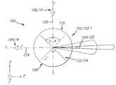
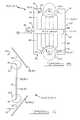
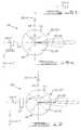
- FIG. 1illustrates a top view of a first embodiment of a multi-beam antenna comprising an electromagnetic lens
- FIG. 2illustrates a side cross-section of the embodiment of FIG. 1
- FIG. 3illustrates a side cross-section of the embodiment of FIG. 1 incorporating a truncated electromagnetic lens
- FIG. 4illustrates a side cross-section of an embodiment illustrating various locations of a dielectric substrate, relative to an electromagnetic lens
- FIG. 5illustrates an embodiment wherein each antenna feed element is operatively coupled to a separate signal
- FIG. 6illustrates an embodiment wherein the switching network is separately located from the dielectric substrate
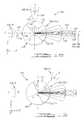
- FIG. 7illustrates a top view of a second embodiment of a multi-beam antenna, comprising a plurality electromagnetic lenses located proximate to one edge of a dielectric substrate;
- FIG. 8illustrates a top view of a third embodiment of a multi-beam antenna, comprising a plurality electromagnetic lenses located proximate to opposite edges of a dielectric substrate;
- FIG. 9illustrates a side view of the third embodiment illustrated in FIG. 8, further comprising a plurality of reflectors
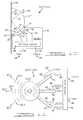
- FIG. 10illustrates a fourth embodiment of a multi-beam antenna, comprising an electromagnetic lens and a reflector
- FIG. 11illustrates a fifth embodiment of a multi-beam antenna
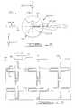
- FIG. 12illustrates a sixth embodiment of a multi-beam antenna incorporating a first embodiment of a selective element
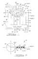
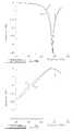
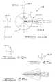
- FIG. 13illustrates an example of a frequency selective surface in accordance with the first embodiment of the selective element
- FIG. 14illustrates the reflectivity as a function of frequency of the frequency selective surface illustrated in FIG. 13;
- FIG. 15illustrates the transmissivity as a function of frequency of the frequency selective surface illustrated in FIG. 13;
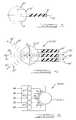
- FIGS. 16 a and 16 billustrate a seventh embodiment of a multi-beam antenna incorporating a second embodiment of the selective element
- FIG. 17illustrates an eighth embodiment of a multi-beam antenna incorporating the second embodiment of the selective element, further incorporating a polarization rotator;
- FIG. 18illustrates a ninth embodiment of a multi-beam antenna incorporating the first embodiment of the selective element
- FIG. 19illustrates a tenth embodiment of a multi-beam antenna incorporating the first embodiment of the selective element.
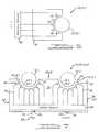
- FIGS. 20 a , 20 b , 20 c and 20 dillustrates an eleventh embodiment of a multi-beam antenna incorporating the first embodiment of the selective element.
- a multi-beam antenna 10 , 10 . 1comprises at least one electromagnetic lens 12 and a plurality of antenna feed elements 14 on a dielectric substrate 16 proximate to a first edge 18 thereof, wherein the plurality of antenna feed elements 14 are adapted to radiate a respective plurality of beams of electromagnetic energy 20 through the at least one electromagnetic lens 12 .
- the at least one electromagnetic lens 12has a first side 22 having a first contour 24 at an intersection of the first side 22 with a reference surface 26 , for example, a plane 26 . 1 .
- the at least one electromagnetic lens 12acts to diffract the electromagnetic wave from the respective antenna feed elements 14 , wherein different antenna feed elements 14 at different locations and in different directions relative to the at least one electromagnetic lens 12 generate different associated beams of electromagnetic energy 20 .
- the at least one electromagnetic lens 12has a refractive index n different from free space, for example, a refractive index n greater than one (1).
- the at least one electromagnetic lens 12may be constructed of a material such as REXOLITETM, TEFLONTM, polyethylene, or polystyrene; or a plurality of different materials having different refractive indices, for example as in a Luneburg lens.
- the shape and size of the at least one electromagnetic lens 12 , the refractive index n thereof, and the relative position of the antenna feed elements 14 to the electromagnetic lens 12are adapted in accordance with the radiation patterns of the antenna feed elements 14 to provide a desired pattern of radiation of the respective beams of electromagnetic energy 20 exiting the second side 28 of the at least one electromagnetic lens 12 .
- the at least one electromagnetic lens 12is illustrated as a spherical lens 12 ′ in FIGS. 1 and 2, the at least one electromagnetic lens 12 is not limited to any one particular design, and may, for example, comprise either a spherical lens, a Luneburg lens, a spherical shell lens, a hemispherical lens, an at least partially spherical lens, an at least partially spherical shell lens, a cylindrical lens, or a rotational lens. Moreover, one or more portions of the electromagnetic lens 12 may be truncated for improved packaging, without significantly impacting the performance of the associated multi-beam antenna 10 , 10 . 1 . For example, FIG. 3 illustrates an at least partially spherical electromagnetic lens 12 ′′ with opposing first 27 and second 29 portions removed therefrom.
- the first edge 18 of the dielectric substrate 16comprises a second contour 30 that is proximate to the first contour 24 .
- the first edge 18 of the dielectric substrate 16is located on the reference surface 26 , and is positioned proximate to the first side 22 of one of the at least one electromagnetic lens 12 .
- the dielectric substrate 16is located relative to the electromagnetic lens 12 so as to provide for the diffraction by the at least one electromagnetic lens 12 necessary to form the beams of electromagnetic energy 20 .
- a multi-beam antenna 10comprising a planar dielectric substrate 16 located on reference surface 26 comprising a plane 26 . 1 , in combination with an electromagnetic lens 12 having a center 32 , for example, a spherical lens 12 ′; the plane 26 .
- the dielectric substrate 16may also be displaced relative to the center 32 of the electromagnetic lens 12 , for example on one or the other side of the center 32 as illustrated by dielectric substrates 16 ′ and 16 ′′, which are located on respective reference surfaces 26 ′ and 26 ′′.
- the dielectric substrate 16is, for example, a material with low loss at an operating frequency, for example, DUROIDTM, a TEFLONTM containing material, a ceramic material, or a composite material such as an epoxy/fiberglass composite.
- the dielectric substrate 16comprises a dielectric 16 . 1 of a circuit board 34 , for example, a printed circuit board 34 . 1 comprising at least one conductive layer 36 adhered to dielectric substrate 16 , from which the antenna feed elements 14 and other associated circuit traces 38 are formed, for example, by subtractive technology, for example, chemical or ion etching, or stamping; or additive techniques, for example, deposition, bonding or lamination.
- each antenna feed element 14comprises a least one conductor 40 operatively connected to the dielectric substrate 16 .
- at least one of the antenna feed elements 14comprises an end-fire antenna element 14 . 1 adapted to launch or receive electromagnetic waves in a direction 42 substantially towards or from the first side 22 of the at least one electromagnetic lens 12 , wherein different end-fire antenna elements 14 . 1 are located at different locations along the second contour 30 so as to launch or receive respective electromagnetic waves in different directions 42 .
- An end-fire antenna element 14is located on the dielectric substrate 16 along the second contour 30 of the first edge 18 , wherein each antenna feed element 14 comprises a least one conductor 40 operatively connected to the dielectric substrate 16 .
- at least one of the antenna feed elements 14comprises an end-fire antenna element 14 . 1 adapted to launch or receive electromagnetic waves in a direction 42 substantially towards or from the first side 22 of the at least one electromagnetic lens 12 , wherein different end-fire antenna elements 14 . 1 are located at different locations along the second contour 30 so as to launch or receive respective electromagnetic
- a Yagi-Uda antennamay, for example, comprise either a Yagi-Uda antenna, a coplanar horn antenna (also known as a tapered slot antenna), a Vivaldi antenna, a tapered dielectric rod, a slot antenna, a dipole antenna, or a helical antenna, each of which is capable of being formed on the dielectric substrate 16 , for example, from a printed circuit board 34 . 1 , for example, by subtractive technology, for example, chemical or ion etching, or stamping; or additive techniques, for example, deposition, bonding or lamination.
- the antenna feed elements 14may be used for transmitting, receiving or both.
- the direction 42 of the one or more beams of electromagnetic energy 20 through the electromagnetic lens 12 , 12 ′is responsive to the relative location of the dielectric substrate 16 , 16 ′ or 16 ′′ and the associated reference surface 26 , 26 ′ or 26 ′′ relative to the center 32 of the electromagnetic lens 12 .
- the directions 42 of the one or more beams of electromagnetic energy 20are nominally aligned with the reference surface 26 .
- the resulting one or more beams of electromagnetic energy 20 ′propagate in directions 42 ′ below the center 32 .
- the resulting one or more beams of electromagnetic energy 20 ′′propagate in directions 42 ′′ above the center 32 .
- the multi-beam antenna 10may further comprise at least one transmission line 44 on the dielectric substrate 16 operatively connected to a feed port 46 of one of the plurality of antenna feed elements 14 for feeding a signal to the associated antenna feed element 14 .
- the at least one transmission line 44may comprise either a stripline, a microstrip line, an inverted microstrip line, a slotline, an image line, an insulated image line, a tapped image line, a coplanar stripline, or a coplanar waveguide line formed on the dielectric substrate 16 , for example, from a printed circuit board 34 . 1 , for example, by subtractive technology, for example, chemical or ion etching, or stamping; or additive techniques, for example, deposition, bonding or lamination.
- the multi-beam antenna 10may further comprise a switching network 48 having at least one input 50 and a plurality of outputs 52 , wherein the at least one input 50 is operatively connected—for example, via at least one above described transmission line 44 —to a corporate antenna feed port 54 , and each output 52 of the plurality of outputs 52 is connected—for example, via at least one above described transmission line 44 —to a respective feed port 46 of a different antenna feed element 14 of the plurality of antenna feed elements 14 .
- the switching network 48further comprises at least one control port 56 for controlling which outputs 52 are connected to the at least one input 50 at a given time.
- the switching network 48may, for example, comprise either a plurality of micro-mechanical switches, PIN diode switches, transistor switches, or a combination thereof, and may, for example, be operatively connected to the dielectric substrate 16 , for example, by surface mount to an associated conductive layer 36 of a printed circuit board 34 . 1 .
- a feed signal 58 applied to the corporate antenna feed port 54is either blocked—for example, by an open circuit, by reflection or by absorption,—or switched to the associated feed port 46 of one or more antenna feed elements 14 , via one or more associated transmission lines 44 , by the switching network 48 , responsive to a control signal 60 applied to the control port 56 .
- the feed signal 58may either comprise a single signal common to each antenna feed element 14 , or a plurality of signals associated with different antenna feed elements 14 .
- Each antenna feed element 14 to which the feed signal 58 is appliedlaunches an associated electromagnetic wave into the first side 22 of the associated electromagnetic lens 12 , which is diffracted thereby to form an associated beam of electromagnetic energy 20 .
- the associated beams of electromagnetic energy 20 launched by different antenna feed elements 14propagate in different associated directions 42 .
- the various beams of electromagnetic energy 20may be generated individually at different times so as to provided for a scanned beam of electromagnetic energy 20 . Alternately, two or more beams of electromagnetic energy 20 may be generated simultaneously.
- different antenna feed elements 14may be driven by different frequencies that, for example, are either directly switched to the respective antenna feed elements 14 , or switched via an associated switching network 48 having a plurality of inputs 50 , at least some of which are each connected to different feed signals 58 .
- the multi-beam antenna 10 , 10 . 1may be adapted so that the respective signals are associated with the respective antenna feed elements 14 in a one-to-one relationship, thereby precluding the need for an associated switching network 48 .
- each antenna feed element 14can be operatively connected to an associated signal 59 through an associated processing element 61 .
- the respective antenna feed elements 14are used to receive electromagnetic energy, and the respective processing elements 61 comprise detectors.
- the respective antenna feed elements 14are used to both transmit and receive electromagnetic energy, and the respective processing elements 61 comprise transmit/receive modules or transceivers.
- the switching network 48if used, need not be collocated on a common dielectric substrate 16 , but can be separately located, as, for example, may be useful for low frequency applications, for example, 1-20 GHz.
- a multi-beam antenna 10 ′comprises at least a first 12 . 1 and a second 12 . 2 electromagnetic lens, each having a first side 22 . 1 , 22 . 2 with a corresponding first contour 24 . 1 , 24 . 2 at an intersection of the respective first side 22 . 1 , 22 . 2 with the reference surface 26 .
- the dielectric substrate 16comprises at least a second edge 62 comprising a third contour 64 , wherein the second contour 30 is proximate to the first contour 24 . 1 of the first electromagnetic lens 12 . 1 and the third contour 64 is proximate to the first contour 24 . 2 of the second electromagnetic lens 12 . 2 .
- the second edge 62is the same as the first edge 18 and the second 30 and third 64 contours are displaced from one another along the first edge 18 of the dielectric substrate 16 .
- the second edge 62is different from the first edge 18 , and more particularly is opposite to the first edge 18 of the dielectric substrate 16 .
- a multi-beam antenna 10 ′′comprises at least one reflector 66 , wherein the reference surface 26 intersects the at least one reflector 66 and one of the at least one electromagnetic lens 12 is located between the dielectric substrate 16 and the reflector 66 .
- the at least one reflector 66is adapted to reflect electromagnetic energy propagated through the at least one electromagnetic lens 12 after being generated by at least one of the plurality of antenna feed elements 14 .
- a third embodiment of the multi-beam antenna 10comprises at least first 66 . 1 and second 66 . 2 reflectors wherein the first electromagnetic lens 12 . 1 is located between the dielectric substrate 16 and the first reflector 66 . 1 , the second electromagnetic lens 12 .
- the first reflector 66 . 1is adapted to reflect electromagnetic energy propagated through the first electromagnetic lens 12 . 1 after being generated by at least one of the plurality of antenna feed elements 14 on the second contour 30
- the second reflector 66 . 2is adapted to reflect electromagnetic energy propagated through the second electromagnetic lens 12 . 2 after being generated by at least one of the plurality of antenna feed elements 14 on the third contour 64 .
- the first 66 . 1 and second 66 . 2 reflectorsmay be oriented to direct the beams of electromagnetic energy 20 from each side in a common nominal direction, as illustrated in FIG. 9 . Referring to FIG.
- the multi-beam antenna 10 ′′ as illustratedwould provide for scanning in a direction normal to the plane of the illustration. If the dielectric substrate 16 were rotated by 90 degrees with respect to the reflectors 66 . 1 , 66 . 2 , about an axis connecting the respective electromagnetic lenses 12 . 1 , 12 . 1 , then the multi-beam antenna 10 ′′ would provide for scanning in a direction parallel to the plane of the illustration.
- a multi-beam antenna 10 ′′, 10 . 4comprises an at least partially spherical electromagnetic lens 12 ′′′, for example, a hemispherical electromagnetic lens, having a curved surface 68 and a boundary 70 , for example a flat boundary 70 . 1 .
- the multi-beam antenna 10 ′′, 10comprises an at least partially spherical electromagnetic lens 12 ′′′, for example, a hemispherical electromagnetic lens, having a curved surface 68 and a boundary 70 , for example a flat boundary 70 . 1 .
- the multi-beam antenna 10 ′′, 10 . 4further comprises a switching network 48 and a plurality of transmission lines 44 operatively connected to the antenna feed elements 14 as described hereinabove for the other embodiments.
- At least one feed signal 58 applied to a corporate antenna feed port 54is either blocked, or switched to the associated feed port 46 of one or more antenna feed elements 14 , via one or more associated transmission lines 44 , by the switching network 48 responsive to a control signal 60 applied to a control port 56 of the switching network 48 .
- Each antenna feed element 14 to which the feed signal 58 is appliedlaunches an associated electromagnetic wave into the first sector 74 of the associated electromagnetic lens 12 ′′′.
- the electromagnetic wavepropagates through—and is diffracted by—the curved surface 68 , and is then reflected by the reflector 66 proximate to the boundary 70 , whereafter the reflected electromagnetic wave propagates through the electromagnetic lens 12 ′′′ and exits—and is diffracted by—a second sector 76 as an associated beam of electromagnetic energy 20 .
- the reflector 66substantially normal to the reference surface 26 —as illustrated in FIG. 10 —the different beams of electromagnetic energy 20 are directed by the associated antenna feed elements 14 in different directions that are nominally substantially parallel to the reference surface 26 .
- a multi-beam antenna 10 ′′′, 10 . 5comprises an electromagnetic lens 12 and plurality of dielectric substrates 16 , each comprising a set of antenna feed elements 14 and operating in accordance with the description hereinabove.
- Each set of antenna feed elements 14generates (or is capable of generating) an associated set of beams of electromagnetic energy 20 . 1 , 20 . 2 and 20 . 3 , each having associated directions 42 . 1 , 42 . 2 and 42 . 3 , responsive to the associated feed 58 and control 60 signals.
- the associated feed 58 and control 60 signalsare either directly applied to the associated switch network 48 of the respective sets of antenna feed elements 14 , or are applied thereto through a second switch network 78 have associated feed 80 and control 82 ports, each comprising at least one associated signal. Accordingly, the multi-beam antenna 10 ′′′, 10 . 4 provides for transmitting or receiving one or more beams of electromagnetic energy over a three-dimensional space.
- the multi-beam antenna 10provides for a relatively wide field-of-view, and is suitable for a variety of applications, including but not limited to automotive radar, point-to-point communications systems and point-to-multi-point communication systems, over a wide range of frequencies for which the antenna feed elements 14 may be designed to radiate, for example, 1 to 200 GHz. Moreover, the multi-beam antenna 10 may be configured for either mono-static or bi-static operation.
- a multi-beam antenna 100comprises an electromagnetic lens 102 , at least one first antenna feed element 104 , 14 , and at least one second antenna feed element 106 , 14 .
- the electromagnetic lens 102comprises first 108 and second 110 portions, wherein the at least one first antenna feed element 104 , 14 is located proximate to the first portion 108 of the electromagnetic lens 102 , and the at least one second antenna feed element 106 , 14 is located proximate to the second portion 110 of the electromagnetic lens 102 , so that the respective feed elements 104 106 , 14 cooperate with the respective portions 108 , 110 of the electromagnetic lens 102 to which they are proximate.
- the electromagnetic lens 102may comprise either a spherical lens 102 . 1 , a Luneburg lens, a spherical shell lens, a hemispherical lens, an at least partially spherical lens, an at least partially spherical shell lens, a cylindrical lens, or a rotational lens—divided into first 108 and second 110 portions.
- the multi-beam antenna 100further comprises a selective element 112 located between the first 108 and second 110 portions of the electromagnetic lens 102 , wherein the selective element 112 has a transmissivity and a reflectivity that are responsive to an electromagnetic wave property, for example either frequency or polarization.
- the transmissivity of the selective element 112is adapted so that a first electromagnetic wave, in cooperation with the first antenna feed element 104 , 14 and having a first value of the electromagnetic wave property, is substantially transmitted through the selective element 112 so as to propagate in both the first 108 and second 110 portions of the electromagnetic lens 102 .
- the reflectivity of the selective element 112is adapted so that a second electromagnetic wave, in cooperation with the second antenna feed element 106 , 14 and having a second value of the electromagnetic wave property, is substantially reflected by the selective element 112 .
- the selective element 112is adapted with a frequency selective surface 114 —essentially a diplexer—so that the transmissivity and reflectivity thereof are responsive to the frequency of an electromagnetic wave impinging thereon.
- a first electromagnetic wave having a first carrier frequency f 1 and cooperating with the first antenna feed element 104 , 14is transmitted, with relatively little attenuation, through the selective element 112
- a second electromagnetic wave having a second carrier frequency f 2 —different from the first carrier frequency f 1 —and cooperating with the second antenna feed element 106 , 14is reflected, with relatively little attenuation, by the selective element 112 .
- the frequency selective surface 114can be constructed by forming a periodic structure of conductive elements, e.g. by etching a conductive sheet on a substrate material having a relatively low dielectric constant, e.g. DUROIDTM or TEFLONTM.
- the frequency selective surface 114is formed by a field of what are known as Jerusalem Crosses 116 , which provides for reflectivity and transmissivity characteristics illustrated in FIGS. 14 and 15 respectively, wherein the frequency selective surface 114 is sized so as to substantially transmit a first electromagnetic wave having an associated first carrier frequency f 1 of 77 GHz, and to substantially reflect a second electromagnetic wave having an associated first carrier frequency f 1 of 24 GHz.
- Jerusalem Crosses 116which provides for reflectivity and transmissivity characteristics illustrated in FIGS. 14 and 15 respectively.
- Each Jerusalem Cross 116is separated from a surrounding conductive surface 118 by a slot 120 that is etched thereinto, wherein the slot 120 has an associated slot width ws.
- Each Jerusalem Cross 116comprises four legs 122 of leg length L and leg width wm extending from a central square hub and forming a cross. Adjacent Jerusalem Crosses 116 are separated from one another by the associated slots 120 , and by conductive gaps G, so as to form a periodic structure with a periodicity DX in both associated directions of the Jerusalem Crosses 116 .
- the frequency selective surface 114comprises a periodic structure of conductive elements, for example, located on a dielectric substrate, for example, substantially located on a plane.
- the conductive elementsneed not necessarily be located on a substrate.
- the frequency selective surface 114could be constructed from a conductive material with periodic holes or openings of appropriate size, shape and spacing.
- the frequency selective surface 114may comprise a conductive layer on one or both inner surfaces of the respective first 108 and second 110 portions of the electromagnetic lens 102 .
- FIG. 13illustrates a Jerusalem Cross 116 as a kernel element of the associate periodic structure of the frequency selective surface 114
- other shapes for the kernel elementare also possible, for example circular, doughnut, rectangular, square, or potent cross, for example, as illustrated in the following technical papers that are incorporated herein by reference: “Antenna Design on Periodic and Aperiodic Structures” by Zhifang Li, John L. Volakis and Panos Y.
- the lower frequency electromagnetic waveit is beneficial for the lower frequency electromagnetic wave to have a wider field of view. Accordingly, it can be beneficial for the first carrier frequency f 1 (of the transmitted electromagnetic wave) to have the lower frequency (e.g. 24 GHz), which can be facilitated with a multiple layer frequency selective surface 114 .
- the first carrier frequency f 1of the transmitted electromagnetic wave
- the frequency selective surface 114may comprise either a single layer or a multiple layer.
- a multiple layer frequency selective surface 114may provide for controlling the harmonic modes, for example, as generated by the lower frequency radiation, thereby improving the transmission of the lower frequency radiation through the frequency selective surface 114 , so as to provide for a wider field of view of the associated radiation pattern extending from the electromagnetic lens 102 .
- the at least one first antenna feed element 104 , 14 and at least one second antenna feed element 106 , 14comprises respective end-fire antenna elements adapted to launch electromagnetic waves in a direction substantially towards the first 108 and second 110 portions of the at least one electromagnetic lens 102 respectively.
- each of the respective end-fire antenna elementsmay be either a Yagi-Uda antenna, a coplanar horn antenna, a Vivaldi antenna, a tapered dielectric rod, a slot antenna, a dipole antenna, or a helical antenna.
- the at least one first antenna feed element 104 , 14has a corresponding at least one first axis of principal gain 124 , which is directed through both the first 108 and second 110 portions of the electromagnetic lens 102
- the at least one second antenna feed element 106 , 14has a corresponding at least one second axis of principal gain 126 , which is directed through at least the second portion 110 of the electromagnetic lens 102
- the at least one second antenna feed element 106 , 14 and the selective element 112are adapted so that a reflection at least one second axis of principal gain 126 from the selective element 112 is generally aligned with at least one first axis of principal gain 124 in the second portion 110 of the electromagnetic lens 102 .
- a multi-beam antenna 128incorporates a polarization selective element 130 for which the reflectivity or transmissivity thereof is responsive to the polarization of the electromagnetic wave impinging thereon. More particularly, one of two orthogonal polarizations is substantially transmitted by the polarization selective element 130 , and the other of two orthogonal polarizations is substantially reflected by the polarization selective element 130 .
- the first electromagnetic wave associated with the first antenna feed element 104 , 14is polarized in the y direction—e.g.
- the polarization selective element 130can be what is known as a polarized reflector, wherein the second antenna feed element 106 , 14 is adapted to have the same polarization as the polarized reflector.
- a polarized reflective surfacecan be fabricated by etching properly dimensioned parallel metal lines at an associated proper spacing on a relatively low dielectric substrate.
- a polarization rotator 134is incorporated between the first antenna feed element 104 , 14 and the electromagnetic lens 102 of the electromagnetic lens 102 , for example, so that the first 104 and second 106 antenna feed elements 14 can be constructed on a common substrate.
- the first portion 108 of the electromagnetic lens 102may be adapted to incorporated an associated polarization rotator.
- the polarization selective element 130 and associated second antenna feed element 106 , 14 , or polarization rotator 134 proximate theretomay alternately be adapted as was the first antenna feed element 104 , 14 , or polarization rotator 134 proximate thereto, in the embodiments of FIGS. 16 a and 17 .
- the resulting beam patterns for a polarization selective element 130would be similar to those for a frequency selective surface 114 .
- a multi-beam antenna 136incorporates a plurality of first antenna feed elements 104 , 14 and a plurality of second antenna feed elements 106 , 14 so as to provide for multi-beam coverage by each.
- the plurality of first antenna feed elements 104 , 14has an associated first median axis of principal gain 138
- the plurality of second antenna feed elements 106 , 14has an associated second median axis of principal gain 140 .
- the plurality of first antenna feed elements 104 , 14By orienting the plurality of first antenna feed elements 104 , 14 on the median axis of intended propagation, the associated first electromagnetic wave(s) will propagate through the selective element 112 along the intended direction of propagation.
- the particular angle ⁇is not considered to be limiting.
- a polarization selective element 130can generally operate over a relatively wide range of angles.
- the pluralities of first 104 and second 106 antenna feed elements 106 , 14may be constructed as described hereinabove for the embodiments illustrated in FIGS. 1-5, wherein the direction for at least one the first end-fire antenna elements is different for the direction of at least another the first end-fire antenna element, and the direction for at least one the second end-fire antenna element is different for the direction of at least another the second end-fire antenna element.
- the at least one first antenna feed element 104 , 14comprises a plurality of first antenna feed elements 104 , 14 arranged substantially on a first plane
- the at least one second antenna feed element 106 , 14comprises a plurality of second antenna feed elements 106 , 14 arranged substantially on a second plane.
- the first and second planesare at least substantially parallel to one another in one embodiment, and may be at least substantially coplanar so as to provide for mounting all of the antenna feed elements 104 , 106 , 14 on a common substrate.
- the at least one first antenna feed element 104 , 14has a corresponding first median axis of principal gain 138 , which is directed through both the first 108 and second 110 portion 110 of the electromagnetic lens 102 .
- the at least one second antenna feed element 106 , 14has a corresponding second median axis of principal gain 140 , which is directed through at least the second portion 110 of the electromagnetic lens 102 , and the at least one second antenna feed element 106 , 14 and the selective element 112 are adapted so that a reflection 142 of the second median axis of principal gain 140 from the selective element 112 is generally aligned with the first median axis of principal gain 138 in the second portion 110 of the electromagnetic lens 102 .
- a multi-beam antenna 144is adapted for improved performance, resulting in an offset angle of about 25 degrees for the frequency selective surface 114 illustrated in FIG. 13, for a first carrier frequency f 1 of 77 GHz, and a second carrier frequency f 2 of 24 GHz.
- a multi-beam antenna 146comprises a frequency selective surface 114 oriented orthogonal to that illustrated in FIG. 18, wherein the associated plurality of first antenna feed elements 104 , 14 and the associated plurality of second antenna feed elements 106 , 14 are each orthogonal to the respective orientations illustrated in FIG. 18 . More particularly, the plurality of first antenna feed elements 104 , 14 are oriented substantially in the y-z plane, and the plurality of second antenna feed elements 106 , 14 are oriented substantially in the x-y plane, so that the plurality of first antenna feed elements 104 , 14 and the plurality of second antenna feed elements 106 , 14 are each substantially perpendicular to the x-z plane.
- the multi-beam antenna 100can be used to either transmit or receive electromagnetic waves.
- a first electromagnetic waveis transmitted or received along a first direction through an first portion 108 of an electromagnetic lens 102
- a second electromagnetic waveis transmitted or received through a second portion 110 of the electromagnetic lens 102 .
- a substantial portion of the second electromagnetic waveis reflected from a selective element 112 in a region between the first 108 and second 110 portions of the electromagnetic lens 102 .
- the operations of transmitting or receiving a second electromagnetic wave through a second portion 110 of the electromagnetic lens 102 and reflecting the second electromagnetic wave from the selective element 112 in a region between the first 108 and second portions 110 of the electromagnetic lens 102are adapted so that both the first and second electromagnetic waves propagate along a similar median direction within the second portion 110 of the electromagnetic lens 102 , and the selective element 112 transmits the first electromagnetic wave and reflects the second electromagnetic wave responsive to either a difference in carrier frequency or a difference in polarization of the first and second electromagnetic waves.
- the multi-beam antenna 100 , 128 , 132 , 136 , 144 or 146provides for using a common electromagnetic lens 102 to simultaneously focus electromagnetic waves having two different carrier frequencies f 1 , f 2 , thereby providing for different applications without requiring separate associated apertures, thereby providing for a more compact overall package size.
- One particular application of the multi-beam antenna 100 , 128 , 132 , 136 , 144 or 146is for automotive radar for which 24 GHz radiation would be used for relatively near range, wide field of view, collision avoidance applications, as well as stop and go functionality and parking aid, and 77 GHz radiation would be used for long range autonomous cruise control applications.
Landscapes
- Aerials With Secondary Devices (AREA)
- Variable-Direction Aerials And Aerial Arrays (AREA)
- Radar Systems Or Details Thereof (AREA)
Abstract
Description
Claims (27)
Priority Applications (11)
| Application Number | Priority Date | Filing Date | Title |
|---|---|---|---|
| US10/202,242US6606077B2 (en) | 1999-11-18 | 2002-07-23 | Multi-beam antenna |
| AU2003252110AAU2003252110A1 (en) | 2002-07-23 | 2003-07-23 | Multi-beam antenna |
| JP2004523319AJP2005534231A (en) | 2002-07-23 | 2003-07-23 | Multi-beam antenna |
| EP03765944AEP1537628A4 (en) | 2002-07-23 | 2003-07-23 | Multi-beam antenna |
| PCT/US2003/022944WO2004010534A1 (en) | 2002-07-23 | 2003-07-23 | Multi-beam antenna |
| CNA038177196ACN1672292A (en) | 2002-07-23 | 2003-07-23 | Multi-beam antenna |
| US10/604,716US7042420B2 (en) | 1999-11-18 | 2003-08-12 | Multi-beam antenna |
| US11/161,681US7358913B2 (en) | 1999-11-18 | 2005-08-11 | Multi-beam antenna |
| US11/627,369US7994996B2 (en) | 1999-11-18 | 2007-01-25 | Multi-beam antenna |
| US11/929,791US7800549B2 (en) | 1999-11-18 | 2007-10-30 | Multi-beam antenna |
| US11/931,625US7605768B2 (en) | 1999-11-18 | 2007-10-31 | Multi-beam antenna |
Applications Claiming Priority (3)
| Application Number | Priority Date | Filing Date | Title |
|---|---|---|---|
| US16623199P | 1999-11-18 | 1999-11-18 | |
| US09/716,736US6424319B2 (en) | 1999-11-18 | 2000-11-20 | Multi-beam antenna |
| US10/202,242US6606077B2 (en) | 1999-11-18 | 2002-07-23 | Multi-beam antenna |
Related Parent Applications (1)
| Application Number | Title | Priority Date | Filing Date |
|---|---|---|---|
| US09/716,736Continuation-In-PartUS6424319B2 (en) | 1999-11-18 | 2000-11-20 | Multi-beam antenna |
Related Child Applications (1)
| Application Number | Title | Priority Date | Filing Date |
|---|---|---|---|
| US10/604,716Continuation-In-PartUS7042420B2 (en) | 1999-11-18 | 2003-08-12 | Multi-beam antenna |
Publications (2)
| Publication Number | Publication Date |
|---|---|
| US20030006941A1 US20030006941A1 (en) | 2003-01-09 |
| US6606077B2true US6606077B2 (en) | 2003-08-12 |
Family
ID=30769775
Family Applications (1)
| Application Number | Title | Priority Date | Filing Date |
|---|---|---|---|
| US10/202,242Expired - LifetimeUS6606077B2 (en) | 1999-11-18 | 2002-07-23 | Multi-beam antenna |
Country Status (6)
| Country | Link |
|---|---|
| US (1) | US6606077B2 (en) |
| EP (1) | EP1537628A4 (en) |
| JP (1) | JP2005534231A (en) |
| CN (1) | CN1672292A (en) |
| AU (1) | AU2003252110A1 (en) |
| WO (1) | WO2004010534A1 (en) |
Cited By (182)
| Publication number | Priority date | Publication date | Assignee | Title |
|---|---|---|---|---|
| US20050068251A1 (en)* | 1999-11-18 | 2005-03-31 | Automotive Systems Laboratory, Inc. | Multi-beam antenna |
| US20050219126A1 (en)* | 2004-03-26 | 2005-10-06 | Automotive Systems Laboratory, Inc. | Multi-beam antenna |
| US20060028386A1 (en)* | 1999-11-18 | 2006-02-09 | Ebling James P | Multi-beam antenna |
| US20060125713A1 (en)* | 2002-10-24 | 2006-06-15 | Marc Thevenot | Multiple-beam antenna with photonic bandgap material |
| WO2006031341A3 (en)* | 2004-08-11 | 2006-08-24 | Automotive Systems Lab | Multi-beam antenna |
| US20060267830A1 (en)* | 2005-02-10 | 2006-11-30 | O'boyle Michael E | Automotive radar system with guard beam |
| US20070001918A1 (en)* | 2005-05-05 | 2007-01-04 | Ebling James P | Antenna |
| WO2005094352A3 (en)* | 2004-03-26 | 2007-02-15 | Automotive Systems Lab | Multi-beam antenna |
| US20070195004A1 (en)* | 1999-11-18 | 2007-08-23 | Gabriel Rebeiz | Multi-beam antenna |
| US20080258964A1 (en)* | 2004-12-13 | 2008-10-23 | Thomas Schoeberl | Radar System |
| US20090273508A1 (en)* | 2008-04-30 | 2009-11-05 | Thomas Binzer | Multi-beam radar sensor |
| US7667665B1 (en)* | 2006-11-01 | 2010-02-23 | Hrl Laboratories, Llc | Dual frequency aperture antenna |
| US20100117891A1 (en)* | 2007-04-02 | 2010-05-13 | National Ins. Of Info. And Communications Tech. | Microwave/millimeter wave sensor apparatus |
| US20130082889A1 (en)* | 2011-06-20 | 2013-04-04 | Canon Kabushiki Kaisha | Concentric millimeter-waves beam forming antenna system implementation |
| US8881588B2 (en) | 2012-02-23 | 2014-11-11 | Krohne Messtechnik Gmbh | Dielectric antenna and fill level sensor using the radar principle |
| US9312919B1 (en) | 2014-10-21 | 2016-04-12 | At&T Intellectual Property I, Lp | Transmission device with impairment compensation and methods for use therewith |
| US9461706B1 (en) | 2015-07-31 | 2016-10-04 | At&T Intellectual Property I, Lp | Method and apparatus for exchanging communication signals |
| US9467870B2 (en) | 2013-11-06 | 2016-10-11 | At&T Intellectual Property I, L.P. | Surface-wave communications and methods thereof |
| US9479266B2 (en) | 2013-12-10 | 2016-10-25 | At&T Intellectual Property I, L.P. | Quasi-optical coupler |
| US9490869B1 (en) | 2015-05-14 | 2016-11-08 | At&T Intellectual Property I, L.P. | Transmission medium having multiple cores and methods for use therewith |
| US9503189B2 (en) | 2014-10-10 | 2016-11-22 | At&T Intellectual Property I, L.P. | Method and apparatus for arranging communication sessions in a communication system |
| US9509415B1 (en) | 2015-06-25 | 2016-11-29 | At&T Intellectual Property I, L.P. | Methods and apparatus for inducing a fundamental wave mode on a transmission medium |
| US9520945B2 (en) | 2014-10-21 | 2016-12-13 | At&T Intellectual Property I, L.P. | Apparatus for providing communication services and methods thereof |
| US9525524B2 (en) | 2013-05-31 | 2016-12-20 | At&T Intellectual Property I, L.P. | Remote distributed antenna system |
| US9525210B2 (en) | 2014-10-21 | 2016-12-20 | At&T Intellectual Property I, L.P. | Guided-wave transmission device with non-fundamental mode propagation and methods for use therewith |
| US9531427B2 (en) | 2014-11-20 | 2016-12-27 | At&T Intellectual Property I, L.P. | Transmission device with mode division multiplexing and methods for use therewith |
| US9564947B2 (en) | 2014-10-21 | 2017-02-07 | At&T Intellectual Property I, L.P. | Guided-wave transmission device with diversity and methods for use therewith |
| US9577307B2 (en) | 2014-10-21 | 2017-02-21 | At&T Intellectual Property I, L.P. | Guided-wave transmission device and methods for use therewith |
| US9608692B2 (en) | 2015-06-11 | 2017-03-28 | At&T Intellectual Property I, L.P. | Repeater and methods for use therewith |
| US9608740B2 (en) | 2015-07-15 | 2017-03-28 | At&T Intellectual Property I, L.P. | Method and apparatus for launching a wave mode that mitigates interference |
| US9615269B2 (en) | 2014-10-02 | 2017-04-04 | At&T Intellectual Property I, L.P. | Method and apparatus that provides fault tolerance in a communication network |
| US9628116B2 (en) | 2015-07-14 | 2017-04-18 | At&T Intellectual Property I, L.P. | Apparatus and methods for transmitting wireless signals |
| US9628854B2 (en) | 2014-09-29 | 2017-04-18 | At&T Intellectual Property I, L.P. | Method and apparatus for distributing content in a communication network |
| US9640850B2 (en) | 2015-06-25 | 2017-05-02 | At&T Intellectual Property I, L.P. | Methods and apparatus for inducing a non-fundamental wave mode on a transmission medium |
| US9653770B2 (en) | 2014-10-21 | 2017-05-16 | At&T Intellectual Property I, L.P. | Guided wave coupler, coupling module and methods for use therewith |
| US9654173B2 (en) | 2014-11-20 | 2017-05-16 | At&T Intellectual Property I, L.P. | Apparatus for powering a communication device and methods thereof |
| US9667317B2 (en) | 2015-06-15 | 2017-05-30 | At&T Intellectual Property I, L.P. | Method and apparatus for providing security using network traffic adjustments |
| US9680670B2 (en) | 2014-11-20 | 2017-06-13 | At&T Intellectual Property I, L.P. | Transmission device with channel equalization and control and methods for use therewith |
| US9685992B2 (en) | 2014-10-03 | 2017-06-20 | At&T Intellectual Property I, L.P. | Circuit panel network and methods thereof |
| US9692101B2 (en) | 2014-08-26 | 2017-06-27 | At&T Intellectual Property I, L.P. | Guided wave couplers for coupling electromagnetic waves between a waveguide surface and a surface of a wire |
| US9699785B2 (en) | 2012-12-05 | 2017-07-04 | At&T Intellectual Property I, L.P. | Backhaul link for distributed antenna system |
| US9705571B2 (en) | 2015-09-16 | 2017-07-11 | At&T Intellectual Property I, L.P. | Method and apparatus for use with a radio distributed antenna system |
| US9705561B2 (en) | 2015-04-24 | 2017-07-11 | At&T Intellectual Property I, L.P. | Directional coupling device and methods for use therewith |
| US9722318B2 (en) | 2015-07-14 | 2017-08-01 | At&T Intellectual Property I, L.P. | Method and apparatus for coupling an antenna to a device |
| US9729197B2 (en) | 2015-10-01 | 2017-08-08 | At&T Intellectual Property I, L.P. | Method and apparatus for communicating network management traffic over a network |
| US9735833B2 (en) | 2015-07-31 | 2017-08-15 | At&T Intellectual Property I, L.P. | Method and apparatus for communications management in a neighborhood network |
| US9742462B2 (en) | 2014-12-04 | 2017-08-22 | At&T Intellectual Property I, L.P. | Transmission medium and communication interfaces and methods for use therewith |
| US9749053B2 (en) | 2015-07-23 | 2017-08-29 | At&T Intellectual Property I, L.P. | Node device, repeater and methods for use therewith |
| US9749013B2 (en) | 2015-03-17 | 2017-08-29 | At&T Intellectual Property I, L.P. | Method and apparatus for reducing attenuation of electromagnetic waves guided by a transmission medium |
| US9748626B2 (en) | 2015-05-14 | 2017-08-29 | At&T Intellectual Property I, L.P. | Plurality of cables having different cross-sectional shapes which are bundled together to form a transmission medium |
| US9755697B2 (en) | 2014-09-15 | 2017-09-05 | At&T Intellectual Property I, L.P. | Method and apparatus for sensing a condition in a transmission medium of electromagnetic waves |
| US9762289B2 (en) | 2014-10-14 | 2017-09-12 | At&T Intellectual Property I, L.P. | Method and apparatus for transmitting or receiving signals in a transportation system |
| US9769020B2 (en) | 2014-10-21 | 2017-09-19 | At&T Intellectual Property I, L.P. | Method and apparatus for responding to events affecting communications in a communication network |
| US9769128B2 (en) | 2015-09-28 | 2017-09-19 | At&T Intellectual Property I, L.P. | Method and apparatus for encryption of communications over a network |
| US9780834B2 (en) | 2014-10-21 | 2017-10-03 | At&T Intellectual Property I, L.P. | Method and apparatus for transmitting electromagnetic waves |
| US9793951B2 (en) | 2015-07-15 | 2017-10-17 | At&T Intellectual Property I, L.P. | Method and apparatus for launching a wave mode that mitigates interference |
| US9793954B2 (en) | 2015-04-28 | 2017-10-17 | At&T Intellectual Property I, L.P. | Magnetic coupling device and methods for use therewith |
| US9793955B2 (en) | 2015-04-24 | 2017-10-17 | At&T Intellectual Property I, Lp | Passive electrical coupling device and methods for use therewith |
| US9800327B2 (en) | 2014-11-20 | 2017-10-24 | At&T Intellectual Property I, L.P. | Apparatus for controlling operations of a communication device and methods thereof |
| US9820146B2 (en) | 2015-06-12 | 2017-11-14 | At&T Intellectual Property I, L.P. | Method and apparatus for authentication and identity management of communicating devices |
| US9838896B1 (en) | 2016-12-09 | 2017-12-05 | At&T Intellectual Property I, L.P. | Method and apparatus for assessing network coverage |
| US9836957B2 (en) | 2015-07-14 | 2017-12-05 | At&T Intellectual Property I, L.P. | Method and apparatus for communicating with premises equipment |
| US9847850B2 (en) | 2014-10-14 | 2017-12-19 | At&T Intellectual Property I, L.P. | Method and apparatus for adjusting a mode of communication in a communication network |
| US9847566B2 (en) | 2015-07-14 | 2017-12-19 | At&T Intellectual Property I, L.P. | Method and apparatus for adjusting a field of a signal to mitigate interference |
| US9853342B2 (en) | 2015-07-14 | 2017-12-26 | At&T Intellectual Property I, L.P. | Dielectric transmission medium connector and methods for use therewith |
| US9860075B1 (en) | 2016-08-26 | 2018-01-02 | At&T Intellectual Property I, L.P. | Method and communication node for broadband distribution |
| US9865911B2 (en) | 2015-06-25 | 2018-01-09 | At&T Intellectual Property I, L.P. | Waveguide system for slot radiating first electromagnetic waves that are combined into a non-fundamental wave mode second electromagnetic wave on a transmission medium |
| US9866309B2 (en) | 2015-06-03 | 2018-01-09 | At&T Intellectual Property I, Lp | Host node device and methods for use therewith |
| US9871283B2 (en) | 2015-07-23 | 2018-01-16 | At&T Intellectual Property I, Lp | Transmission medium having a dielectric core comprised of plural members connected by a ball and socket configuration |
| US9871282B2 (en) | 2015-05-14 | 2018-01-16 | At&T Intellectual Property I, L.P. | At least one transmission medium having a dielectric surface that is covered at least in part by a second dielectric |
| US9876571B2 (en) | 2015-02-20 | 2018-01-23 | At&T Intellectual Property I, Lp | Guided-wave transmission device with non-fundamental mode propagation and methods for use therewith |
| US9876605B1 (en) | 2016-10-21 | 2018-01-23 | At&T Intellectual Property I, L.P. | Launcher and coupling system to support desired guided wave mode |
| US9876264B2 (en) | 2015-10-02 | 2018-01-23 | At&T Intellectual Property I, Lp | Communication system, guided wave switch and methods for use therewith |
| US9882257B2 (en) | 2015-07-14 | 2018-01-30 | At&T Intellectual Property I, L.P. | Method and apparatus for launching a wave mode that mitigates interference |
| US9882277B2 (en) | 2015-10-02 | 2018-01-30 | At&T Intellectual Property I, Lp | Communication device and antenna assembly with actuated gimbal mount |
| US9893795B1 (en) | 2016-12-07 | 2018-02-13 | At&T Intellectual Property I, Lp | Method and repeater for broadband distribution |
| US9906269B2 (en) | 2014-09-17 | 2018-02-27 | At&T Intellectual Property I, L.P. | Monitoring and mitigating conditions in a communication network |
| US9904535B2 (en) | 2015-09-14 | 2018-02-27 | At&T Intellectual Property I, L.P. | Method and apparatus for distributing software |
| US9912382B2 (en) | 2015-06-03 | 2018-03-06 | At&T Intellectual Property I, Lp | Network termination and methods for use therewith |
| US9912419B1 (en) | 2016-08-24 | 2018-03-06 | At&T Intellectual Property I, L.P. | Method and apparatus for managing a fault in a distributed antenna system |
| US9911020B1 (en) | 2016-12-08 | 2018-03-06 | At&T Intellectual Property I, L.P. | Method and apparatus for tracking via a radio frequency identification device |
| US9912027B2 (en) | 2015-07-23 | 2018-03-06 | At&T Intellectual Property I, L.P. | Method and apparatus for exchanging communication signals |
| US9913139B2 (en) | 2015-06-09 | 2018-03-06 | At&T Intellectual Property I, L.P. | Signal fingerprinting for authentication of communicating devices |
| US9917341B2 (en) | 2015-05-27 | 2018-03-13 | At&T Intellectual Property I, L.P. | Apparatus and method for launching electromagnetic waves and for modifying radial dimensions of the propagating electromagnetic waves |
| US9927517B1 (en) | 2016-12-06 | 2018-03-27 | At&T Intellectual Property I, L.P. | Apparatus and methods for sensing rainfall |
| US9948354B2 (en) | 2015-04-28 | 2018-04-17 | At&T Intellectual Property I, L.P. | Magnetic coupling device with reflective plate and methods for use therewith |
| US9948333B2 (en) | 2015-07-23 | 2018-04-17 | At&T Intellectual Property I, L.P. | Method and apparatus for wireless communications to mitigate interference |
| US9954287B2 (en) | 2014-11-20 | 2018-04-24 | At&T Intellectual Property I, L.P. | Apparatus for converting wireless signals and electromagnetic waves and methods thereof |
| US9967173B2 (en) | 2015-07-31 | 2018-05-08 | At&T Intellectual Property I, L.P. | Method and apparatus for authentication and identity management of communicating devices |
| US9973940B1 (en) | 2017-02-27 | 2018-05-15 | At&T Intellectual Property I, L.P. | Apparatus and methods for dynamic impedance matching of a guided wave launcher |
| US9991580B2 (en) | 2016-10-21 | 2018-06-05 | At&T Intellectual Property I, L.P. | Launcher and coupling system for guided wave mode cancellation |
| US9997819B2 (en) | 2015-06-09 | 2018-06-12 | At&T Intellectual Property I, L.P. | Transmission medium and method for facilitating propagation of electromagnetic waves via a core |
| US9998870B1 (en) | 2016-12-08 | 2018-06-12 | At&T Intellectual Property I, L.P. | Method and apparatus for proximity sensing |
| US9999038B2 (en) | 2013-05-31 | 2018-06-12 | At&T Intellectual Property I, L.P. | Remote distributed antenna system |
| US10009901B2 (en) | 2015-09-16 | 2018-06-26 | At&T Intellectual Property I, L.P. | Method, apparatus, and computer-readable storage medium for managing utilization of wireless resources between base stations |
| US10009067B2 (en) | 2014-12-04 | 2018-06-26 | At&T Intellectual Property I, L.P. | Method and apparatus for configuring a communication interface |
| US10009063B2 (en) | 2015-09-16 | 2018-06-26 | At&T Intellectual Property I, L.P. | Method and apparatus for use with a radio distributed antenna system having an out-of-band reference signal |
| US10009065B2 (en) | 2012-12-05 | 2018-06-26 | At&T Intellectual Property I, L.P. | Backhaul link for distributed antenna system |
| US10020587B2 (en) | 2015-07-31 | 2018-07-10 | At&T Intellectual Property I, L.P. | Radial antenna and methods for use therewith |
| US10020844B2 (en) | 2016-12-06 | 2018-07-10 | T&T Intellectual Property I, L.P. | Method and apparatus for broadcast communication via guided waves |
| US10027397B2 (en) | 2016-12-07 | 2018-07-17 | At&T Intellectual Property I, L.P. | Distributed antenna system and methods for use therewith |
| US10033107B2 (en) | 2015-07-14 | 2018-07-24 | At&T Intellectual Property I, L.P. | Method and apparatus for coupling an antenna to a device |
| US10033108B2 (en) | 2015-07-14 | 2018-07-24 | At&T Intellectual Property I, L.P. | Apparatus and methods for generating an electromagnetic wave having a wave mode that mitigates interference |
| US10044409B2 (en) | 2015-07-14 | 2018-08-07 | At&T Intellectual Property I, L.P. | Transmission medium and methods for use therewith |
| US10051483B2 (en) | 2015-10-16 | 2018-08-14 | At&T Intellectual Property I, L.P. | Method and apparatus for directing wireless signals |
| US10051629B2 (en) | 2015-09-16 | 2018-08-14 | At&T Intellectual Property I, L.P. | Method and apparatus for use with a radio distributed antenna system having an in-band reference signal |
| US10069535B2 (en) | 2016-12-08 | 2018-09-04 | At&T Intellectual Property I, L.P. | Apparatus and methods for launching electromagnetic waves having a certain electric field structure |
| US10074890B2 (en) | 2015-10-02 | 2018-09-11 | At&T Intellectual Property I, L.P. | Communication device and antenna with integrated light assembly |
| US10079661B2 (en) | 2015-09-16 | 2018-09-18 | At&T Intellectual Property I, L.P. | Method and apparatus for use with a radio distributed antenna system having a clock reference |
| US10090594B2 (en) | 2016-11-23 | 2018-10-02 | At&T Intellectual Property I, L.P. | Antenna system having structural configurations for assembly |
| US10090606B2 (en) | 2015-07-15 | 2018-10-02 | At&T Intellectual Property I, L.P. | Antenna system with dielectric array and methods for use therewith |
| US10103422B2 (en) | 2016-12-08 | 2018-10-16 | At&T Intellectual Property I, L.P. | Method and apparatus for mounting network devices |
| US10103801B2 (en) | 2015-06-03 | 2018-10-16 | At&T Intellectual Property I, L.P. | Host node device and methods for use therewith |
| US10135145B2 (en) | 2016-12-06 | 2018-11-20 | At&T Intellectual Property I, L.P. | Apparatus and methods for generating an electromagnetic wave along a transmission medium |
| US10135147B2 (en) | 2016-10-18 | 2018-11-20 | At&T Intellectual Property I, L.P. | Apparatus and methods for launching guided waves via an antenna |
| US10135146B2 (en) | 2016-10-18 | 2018-11-20 | At&T Intellectual Property I, L.P. | Apparatus and methods for launching guided waves via circuits |
| US10136434B2 (en) | 2015-09-16 | 2018-11-20 | At&T Intellectual Property I, L.P. | Method and apparatus for use with a radio distributed antenna system having an ultra-wideband control channel |
| US10139820B2 (en) | 2016-12-07 | 2018-11-27 | At&T Intellectual Property I, L.P. | Method and apparatus for deploying equipment of a communication system |
| US10142086B2 (en) | 2015-06-11 | 2018-11-27 | At&T Intellectual Property I, L.P. | Repeater and methods for use therewith |
| US10144036B2 (en) | 2015-01-30 | 2018-12-04 | At&T Intellectual Property I, L.P. | Method and apparatus for mitigating interference affecting a propagation of electromagnetic waves guided by a transmission medium |
| US10148016B2 (en) | 2015-07-14 | 2018-12-04 | At&T Intellectual Property I, L.P. | Apparatus and methods for communicating utilizing an antenna array |
| US10154493B2 (en) | 2015-06-03 | 2018-12-11 | At&T Intellectual Property I, L.P. | Network termination and methods for use therewith |
| US10170840B2 (en) | 2015-07-14 | 2019-01-01 | At&T Intellectual Property I, L.P. | Apparatus and methods for sending or receiving electromagnetic signals |
| US10168695B2 (en) | 2016-12-07 | 2019-01-01 | At&T Intellectual Property I, L.P. | Method and apparatus for controlling an unmanned aircraft |
| US10178445B2 (en) | 2016-11-23 | 2019-01-08 | At&T Intellectual Property I, L.P. | Methods, devices, and systems for load balancing between a plurality of waveguides |
| US10205655B2 (en) | 2015-07-14 | 2019-02-12 | At&T Intellectual Property I, L.P. | Apparatus and methods for communicating utilizing an antenna array and multiple communication paths |
| US10224634B2 (en) | 2016-11-03 | 2019-03-05 | At&T Intellectual Property I, L.P. | Methods and apparatus for adjusting an operational characteristic of an antenna |
| US10225025B2 (en) | 2016-11-03 | 2019-03-05 | At&T Intellectual Property I, L.P. | Method and apparatus for detecting a fault in a communication system |
| US10243270B2 (en) | 2016-12-07 | 2019-03-26 | At&T Intellectual Property I, L.P. | Beam adaptive multi-feed dielectric antenna system and methods for use therewith |
| US10243784B2 (en) | 2014-11-20 | 2019-03-26 | At&T Intellectual Property I, L.P. | System for generating topology information and methods thereof |
| US10264586B2 (en) | 2016-12-09 | 2019-04-16 | At&T Mobility Ii Llc | Cloud-based packet controller and methods for use therewith |
| US10291311B2 (en) | 2016-09-09 | 2019-05-14 | At&T Intellectual Property I, L.P. | Method and apparatus for mitigating a fault in a distributed antenna system |
| US10291334B2 (en) | 2016-11-03 | 2019-05-14 | At&T Intellectual Property I, L.P. | System for detecting a fault in a communication system |
| US10298293B2 (en) | 2017-03-13 | 2019-05-21 | At&T Intellectual Property I, L.P. | Apparatus of communication utilizing wireless network devices |
| US10305190B2 (en) | 2016-12-01 | 2019-05-28 | At&T Intellectual Property I, L.P. | Reflecting dielectric antenna system and methods for use therewith |
| US10312567B2 (en) | 2016-10-26 | 2019-06-04 | At&T Intellectual Property I, L.P. | Launcher with planar strip antenna and methods for use therewith |
| US10320586B2 (en) | 2015-07-14 | 2019-06-11 | At&T Intellectual Property I, L.P. | Apparatus and methods for generating non-interfering electromagnetic waves on an insulated transmission medium |
| US10326494B2 (en) | 2016-12-06 | 2019-06-18 | At&T Intellectual Property I, L.P. | Apparatus for measurement de-embedding and methods for use therewith |
| US10326689B2 (en) | 2016-12-08 | 2019-06-18 | At&T Intellectual Property I, L.P. | Method and system for providing alternative communication paths |
| US10341142B2 (en) | 2015-07-14 | 2019-07-02 | At&T Intellectual Property I, L.P. | Apparatus and methods for generating non-interfering electromagnetic waves on an uninsulated conductor |
| US10340573B2 (en) | 2016-10-26 | 2019-07-02 | At&T Intellectual Property I, L.P. | Launcher with cylindrical coupling device and methods for use therewith |
| US10340601B2 (en) | 2016-11-23 | 2019-07-02 | At&T Intellectual Property I, L.P. | Multi-antenna system and methods for use therewith |
| US10340600B2 (en) | 2016-10-18 | 2019-07-02 | At&T Intellectual Property I, L.P. | Apparatus and methods for launching guided waves via plural waveguide systems |
| US10340983B2 (en) | 2016-12-09 | 2019-07-02 | At&T Intellectual Property I, L.P. | Method and apparatus for surveying remote sites via guided wave communications |
| US10340603B2 (en) | 2016-11-23 | 2019-07-02 | At&T Intellectual Property I, L.P. | Antenna system having shielded structural configurations for assembly |
| US10348391B2 (en) | 2015-06-03 | 2019-07-09 | At&T Intellectual Property I, L.P. | Client node device with frequency conversion and methods for use therewith |
| US10355367B2 (en) | 2015-10-16 | 2019-07-16 | At&T Intellectual Property I, L.P. | Antenna structure for exchanging wireless signals |
| US10361489B2 (en) | 2016-12-01 | 2019-07-23 | At&T Intellectual Property I, L.P. | Dielectric dish antenna system and methods for use therewith |
| US10359749B2 (en) | 2016-12-07 | 2019-07-23 | At&T Intellectual Property I, L.P. | Method and apparatus for utilities management via guided wave communication |
| US10374316B2 (en) | 2016-10-21 | 2019-08-06 | At&T Intellectual Property I, L.P. | System and dielectric antenna with non-uniform dielectric |
| US10382976B2 (en) | 2016-12-06 | 2019-08-13 | At&T Intellectual Property I, L.P. | Method and apparatus for managing wireless communications based on communication paths and network device positions |
| US10389029B2 (en) | 2016-12-07 | 2019-08-20 | At&T Intellectual Property I, L.P. | Multi-feed dielectric antenna system with core selection and methods for use therewith |
| US10389037B2 (en) | 2016-12-08 | 2019-08-20 | At&T Intellectual Property I, L.P. | Apparatus and methods for selecting sections of an antenna array and use therewith |
| US10396887B2 (en) | 2015-06-03 | 2019-08-27 | At&T Intellectual Property I, L.P. | Client node device and methods for use therewith |
| US10411356B2 (en) | 2016-12-08 | 2019-09-10 | At&T Intellectual Property I, L.P. | Apparatus and methods for selectively targeting communication devices with an antenna array |
| US10439675B2 (en) | 2016-12-06 | 2019-10-08 | At&T Intellectual Property I, L.P. | Method and apparatus for repeating guided wave communication signals |
| US10446936B2 (en) | 2016-12-07 | 2019-10-15 | At&T Intellectual Property I, L.P. | Multi-feed dielectric antenna system and methods for use therewith |
| US10498044B2 (en) | 2016-11-03 | 2019-12-03 | At&T Intellectual Property I, L.P. | Apparatus for configuring a surface of an antenna |
| US10530505B2 (en) | 2016-12-08 | 2020-01-07 | At&T Intellectual Property I, L.P. | Apparatus and methods for launching electromagnetic waves along a transmission medium |
| US10535928B2 (en) | 2016-11-23 | 2020-01-14 | At&T Intellectual Property I, L.P. | Antenna system and methods for use therewith |
| US10547348B2 (en) | 2016-12-07 | 2020-01-28 | At&T Intellectual Property I, L.P. | Method and apparatus for switching transmission mediums in a communication system |
| US10601494B2 (en) | 2016-12-08 | 2020-03-24 | At&T Intellectual Property I, L.P. | Dual-band communication device and method for use therewith |
| US10637149B2 (en) | 2016-12-06 | 2020-04-28 | At&T Intellectual Property I, L.P. | Injection molded dielectric antenna and methods for use therewith |
| US10650940B2 (en) | 2015-05-15 | 2020-05-12 | At&T Intellectual Property I, L.P. | Transmission medium having a conductive material and methods for use therewith |
| US10665942B2 (en) | 2015-10-16 | 2020-05-26 | At&T Intellectual Property I, L.P. | Method and apparatus for adjusting wireless communications |
| US10679767B2 (en) | 2015-05-15 | 2020-06-09 | At&T Intellectual Property I, L.P. | Transmission medium having a conductive material and methods for use therewith |
| US10694379B2 (en) | 2016-12-06 | 2020-06-23 | At&T Intellectual Property I, L.P. | Waveguide system with device-based authentication and methods for use therewith |
| US10727599B2 (en) | 2016-12-06 | 2020-07-28 | At&T Intellectual Property I, L.P. | Launcher with slot antenna and methods for use therewith |
| US10755542B2 (en) | 2016-12-06 | 2020-08-25 | At&T Intellectual Property I, L.P. | Method and apparatus for surveillance via guided wave communication |
| US10777873B2 (en) | 2016-12-08 | 2020-09-15 | At&T Intellectual Property I, L.P. | Method and apparatus for mounting network devices |
| US10784670B2 (en) | 2015-07-23 | 2020-09-22 | At&T Intellectual Property I, L.P. | Antenna support for aligning an antenna |
| US10811767B2 (en) | 2016-10-21 | 2020-10-20 | At&T Intellectual Property I, L.P. | System and dielectric antenna with convex dielectric radome |
| US10819035B2 (en) | 2016-12-06 | 2020-10-27 | At&T Intellectual Property I, L.P. | Launcher with helical antenna and methods for use therewith |
| US10916969B2 (en) | 2016-12-08 | 2021-02-09 | At&T Intellectual Property I, L.P. | Method and apparatus for providing power using an inductive coupling |
| US10938108B2 (en) | 2016-12-08 | 2021-03-02 | At&T Intellectual Property I, L.P. | Frequency selective multi-feed dielectric antenna system and methods for use therewith |
| US11032819B2 (en) | 2016-09-15 | 2021-06-08 | At&T Intellectual Property I, L.P. | Method and apparatus for use with a radio distributed antenna system having a control channel reference signal |
| US11394124B2 (en)* | 2015-08-05 | 2022-07-19 | Matsing, Inc. | Antenna lens switched beam array for tracking satellites |
| US11431099B2 (en) | 2015-08-05 | 2022-08-30 | Matsing, Inc. | Antenna lens array for azimuth side lobe level reduction |
| US11509056B2 (en)* | 2015-08-05 | 2022-11-22 | Matsing, Inc. | RF lens antenna array with reduced grating lobes |
| US11509057B2 (en) | 2015-08-05 | 2022-11-22 | Matsing, Inc. | RF lens antenna array with reduced grating lobes |
| US11595238B2 (en)* | 2017-01-13 | 2023-02-28 | Matsing, Inc. | Multi-beam MIMO antenna systems and methods |
| US11909113B2 (en) | 2015-08-05 | 2024-02-20 | Matsing, Inc. | Squinted feeds in lens-based array antennas |
Families Citing this family (33)
| Publication number | Priority date | Publication date | Assignee | Title |
|---|---|---|---|---|
| GB0406814D0 (en)* | 2004-03-26 | 2004-08-04 | Bae Systems Plc | An antenna |
| DE102004062496A1 (en)* | 2004-12-24 | 2006-07-06 | Daimlerchrysler Ag | A method of operating a collision avoidance or collision sequence mitigation system of a vehicle and collision avoidance or collision mitigation system |
| US7656345B2 (en) | 2006-06-13 | 2010-02-02 | Ball Aerospace & Technoloiges Corp. | Low-profile lens method and apparatus for mechanical steering of aperture antennas |
| GB2442796A (en)* | 2006-10-11 | 2008-04-16 | John Thornton | Hemispherical lens with a selective reflective planar surface for a multi-beam antenna |
| GB0701087D0 (en)* | 2007-01-19 | 2007-02-28 | Plasma Antennas Ltd | A displaced feed parallel plate antenna |
| JP5761585B2 (en) | 2008-10-07 | 2015-08-12 | 国立研究開発法人情報通信研究機構 | Pulse radar equipment |
| FR2981207B1 (en)* | 2011-10-05 | 2014-03-07 | Centre Nat Etd Spatiales | MULTI-BEAM SOURCE |
| US9425513B2 (en)* | 2013-07-08 | 2016-08-23 | Samsung Electronics Co., Ltd. | Lens with spatial mixed-order bandpass filter |
| US9780457B2 (en)* | 2013-09-09 | 2017-10-03 | Commscope Technologies Llc | Multi-beam antenna with modular luneburg lens and method of lens manufacture |
| EP2869476A1 (en)* | 2013-10-29 | 2015-05-06 | Alcatel Lucent | Transmitter Method For Multiple Antenna Systems, Transmitter Apparatus And Network Node Thereof |
| CN105206970A (en)* | 2015-10-27 | 2015-12-30 | 大连德昌线缆有限公司 | Welding and pressure welding mixed USB terminal |
| WO2017173208A1 (en) | 2016-03-31 | 2017-10-05 | Commscope Technologies Llc | Lensed antennas for use in wireless communications systems |
| CA3033676A1 (en)* | 2016-08-15 | 2018-02-22 | Arizona Board Of Regents On Behalf Of The University Of Arizona | Novel automotive radar using 3d printed luneburg lens |
| US10355721B2 (en)* | 2017-05-01 | 2019-07-16 | Palo Alto Research Center Incorporated | Multi-band radio frequency transparency window in conductive film |
| US10971806B2 (en) | 2017-08-22 | 2021-04-06 | The Boeing Company | Broadband conformal antenna |
| US10746903B2 (en) | 2017-09-20 | 2020-08-18 | The Boeing Company | Gradient index (GRIN) spoke lens and method of operation |
| US11233310B2 (en) | 2018-01-29 | 2022-01-25 | The Boeing Company | Low-profile conformal antenna |
| WO2019195961A1 (en)* | 2018-04-08 | 2019-10-17 | 广东通宇通讯股份有限公司 | Millimeter-wave multibeam lens antenna |
| US10938082B2 (en) | 2018-08-24 | 2021-03-02 | The Boeing Company | Aperture-coupled microstrip-to-waveguide transitions |
| US10923831B2 (en) | 2018-08-24 | 2021-02-16 | The Boeing Company | Waveguide-fed planar antenna array with enhanced circular polarization |
| US10916853B2 (en) | 2018-08-24 | 2021-02-09 | The Boeing Company | Conformal antenna with enhanced circular polarization |
| US10777905B2 (en)* | 2018-09-07 | 2020-09-15 | The Boeing Company | Lens with concentric hemispherical refractive structures |
| CN112789517A (en)* | 2018-10-05 | 2021-05-11 | 京瓷株式会社 | Electronic device, control method for electronic device, and control program for electronic device |
| CN116111319A (en)* | 2019-05-09 | 2023-05-12 | 康普技术有限责任公司 | Base station antenna with skeleton radio frequency lens |
| CN115087883A (en) | 2019-11-25 | 2022-09-20 | 伦威夫公司 | Automobile radar based on gradient refractive index lens |
| CN110988870B (en)* | 2019-12-20 | 2023-08-18 | 北京工业大学 | Millimeter wave imaging system |
| IL272439B2 (en)* | 2020-02-03 | 2023-05-01 | Elta Systems Ltd | Detection of weak signals of unknown parameters |
| US11177548B1 (en) | 2020-05-04 | 2021-11-16 | The Boeing Company | Electromagnetic wave concentration |
| US11385384B2 (en) | 2020-05-12 | 2022-07-12 | The Boeing Company | Spoke dielectric lens |
| CN112436289B (en)* | 2020-11-12 | 2023-04-07 | 佛山蓝谱达科技有限公司 | Wave beam separator |
| CN113285236B (en)* | 2021-03-31 | 2023-07-28 | 无锡朗普达技术有限公司 | Dragon primary lens antenna |
| CN112992694B (en)* | 2021-04-22 | 2021-08-06 | 甬矽电子(宁波)股份有限公司 | Manufacturing method of IC radio frequency antenna packaging structure and IC radio frequency antenna packaging structure |
| US11962089B2 (en)* | 2021-12-30 | 2024-04-16 | T-Mobile Innovations Llc | Luneburg lens signal repeater |
Citations (28)
| Publication number | Priority date | Publication date | Assignee | Title |
|---|---|---|---|---|
| US3761936A (en) | 1971-05-11 | 1973-09-25 | Raytheon Co | Multi-beam array antenna |
| US3972043A (en)* | 1975-02-03 | 1976-07-27 | Northrop Corporation | Cross-polarizing lens reflector |
| US4222054A (en) | 1978-10-30 | 1980-09-09 | Raytheon Company | Radio frequency lens |
| US4268831A (en) | 1979-04-30 | 1981-05-19 | Sperry Corporation | Antenna for scanning a limited spatial sector |
| US4288795A (en) | 1979-10-25 | 1981-09-08 | The United States Of America As Represented By The Secretary Of The Navy | Anastigmatic three-dimensional bootlace lens |
| US4638322A (en) | 1984-02-14 | 1987-01-20 | The Boeing Company | Multiple feed antenna |
| US4641144A (en) | 1984-12-31 | 1987-02-03 | Raytheon Company | Broad beamwidth lens feed |
| US4845507A (en) | 1987-08-07 | 1989-07-04 | Raytheon Company | Modular multibeam radio frequency array antenna system |
| US4983237A (en) | 1988-08-18 | 1991-01-08 | Hughes Aircraft Company | Antenna lamination technique |
| US5099253A (en) | 1989-11-06 | 1992-03-24 | Raytheon Company | Constant beamwidth scanning array |
| US5204686A (en) | 1988-04-06 | 1993-04-20 | Trw Inc. | RF Feed array |
| US5274389A (en) | 1990-06-21 | 1993-12-28 | Raytheon Company | Broadband direction finding system |
| US5347287A (en) | 1991-04-19 | 1994-09-13 | Hughes Missile Systems Company | Conformal phased array antenna |
| US5451969A (en) | 1993-03-22 | 1995-09-19 | Raytheon Company | Dual polarized dual band antenna |
| US5548294A (en) | 1994-08-17 | 1996-08-20 | Teledesic Corporation | Dielectric lens focused scanning beam antenna for satellite communication system |
| US5576721A (en) | 1993-03-31 | 1996-11-19 | Space Systems/Loral, Inc. | Composite multi-beam and shaped beam antenna system |
| US5712643A (en) | 1995-12-05 | 1998-01-27 | Cushcraft Corporation | Planar microstrip Yagi Antenna array |
| US5745082A (en)* | 1993-06-25 | 1998-04-28 | The Secretary Of State For Defence In Her Britannic Majesty's Government Of The United Kingdom Of Great Britain And Northern Ireland | Radiation sensor |
| US5821908A (en) | 1996-03-22 | 1998-10-13 | Ball Aerospace And Technologies Corp. | Spherical lens antenna having an electronically steerable beam |
| US5828344A (en)* | 1990-08-01 | 1998-10-27 | The Secretary Of State For Defence In Her Britannic Majesty's Government Of The United Kingdom Of Great Britain And Northern Ireland | Radiation sensor |
| US5874915A (en) | 1997-08-08 | 1999-02-23 | Raytheon Company | Wideband cylindrical UHF array |
| US5892487A (en) | 1993-02-28 | 1999-04-06 | Thomson Multimedia S.A. | Antenna system |
| US5894288A (en) | 1997-08-08 | 1999-04-13 | Raytheon Company | Wideband end-fire array |
| US5926134A (en) | 1995-09-19 | 1999-07-20 | Dassault Electronique | Electronic scanning antenna |
| US6031501A (en) | 1997-03-19 | 2000-02-29 | Georgia Tech Research Corporation | Low cost compact electronically scanned millimeter wave lens and method |
| US6046703A (en) | 1998-11-10 | 2000-04-04 | Nutex Communication Corp. | Compact wireless transceiver board with directional printed circuit antenna |
| US6061035A (en) | 1997-04-02 | 2000-05-09 | The United States Of America As Represented By The Secretary Of The Army | Frequency-scanned end-fire phased-aray antenna |
| US6424319B2 (en)* | 1999-11-18 | 2002-07-23 | Automotive Systems Laboratory, Inc. | Multi-beam antenna |
Family Cites Families (2)
| Publication number | Priority date | Publication date | Assignee | Title |
|---|---|---|---|---|
| FR2538959A1 (en)* | 1983-01-04 | 1984-07-06 | Thomson Csf | Two-band microwave lens, its method of manufacture and two-band tracking radar antenna |
| US6545645B1 (en)* | 1999-09-10 | 2003-04-08 | Trw Inc. | Compact frequency selective reflective antenna |
- 2002
- 2002-07-23USUS10/202,242patent/US6606077B2/ennot_activeExpired - Lifetime
- 2003
- 2003-07-23WOPCT/US2003/022944patent/WO2004010534A1/enactiveApplication Filing
- 2003-07-23CNCNA038177196Apatent/CN1672292A/enactivePending
- 2003-07-23AUAU2003252110Apatent/AU2003252110A1/ennot_activeAbandoned
- 2003-07-23EPEP03765944Apatent/EP1537628A4/ennot_activeWithdrawn
- 2003-07-23JPJP2004523319Apatent/JP2005534231A/enactivePending
Patent Citations (29)
| Publication number | Priority date | Publication date | Assignee | Title |
|---|---|---|---|---|
| US3761936A (en) | 1971-05-11 | 1973-09-25 | Raytheon Co | Multi-beam array antenna |
| US3972043A (en)* | 1975-02-03 | 1976-07-27 | Northrop Corporation | Cross-polarizing lens reflector |
| US4222054A (en) | 1978-10-30 | 1980-09-09 | Raytheon Company | Radio frequency lens |
| US4268831A (en) | 1979-04-30 | 1981-05-19 | Sperry Corporation | Antenna for scanning a limited spatial sector |
| US4288795A (en) | 1979-10-25 | 1981-09-08 | The United States Of America As Represented By The Secretary Of The Navy | Anastigmatic three-dimensional bootlace lens |
| US4638322A (en) | 1984-02-14 | 1987-01-20 | The Boeing Company | Multiple feed antenna |
| US4641144A (en) | 1984-12-31 | 1987-02-03 | Raytheon Company | Broad beamwidth lens feed |
| US4845507A (en) | 1987-08-07 | 1989-07-04 | Raytheon Company | Modular multibeam radio frequency array antenna system |
| US5204686A (en) | 1988-04-06 | 1993-04-20 | Trw Inc. | RF Feed array |
| US4983237A (en) | 1988-08-18 | 1991-01-08 | Hughes Aircraft Company | Antenna lamination technique |
| US5099253A (en) | 1989-11-06 | 1992-03-24 | Raytheon Company | Constant beamwidth scanning array |
| US5274389A (en) | 1990-06-21 | 1993-12-28 | Raytheon Company | Broadband direction finding system |
| US5828344A (en)* | 1990-08-01 | 1998-10-27 | The Secretary Of State For Defence In Her Britannic Majesty's Government Of The United Kingdom Of Great Britain And Northern Ireland | Radiation sensor |
| US5347287A (en) | 1991-04-19 | 1994-09-13 | Hughes Missile Systems Company | Conformal phased array antenna |
| US5892487A (en) | 1993-02-28 | 1999-04-06 | Thomson Multimedia S.A. | Antenna system |
| US5451969A (en) | 1993-03-22 | 1995-09-19 | Raytheon Company | Dual polarized dual band antenna |
| US5576721A (en) | 1993-03-31 | 1996-11-19 | Space Systems/Loral, Inc. | Composite multi-beam and shaped beam antenna system |
| US5745082A (en)* | 1993-06-25 | 1998-04-28 | The Secretary Of State For Defence In Her Britannic Majesty's Government Of The United Kingdom Of Great Britain And Northern Ireland | Radiation sensor |
| US5548294A (en) | 1994-08-17 | 1996-08-20 | Teledesic Corporation | Dielectric lens focused scanning beam antenna for satellite communication system |
| US5926134A (en) | 1995-09-19 | 1999-07-20 | Dassault Electronique | Electronic scanning antenna |
| US5913549A (en) | 1995-12-05 | 1999-06-22 | Cushcraft Corporation | Planar microstrip Yagi antenna array and process for making same |
| US5712643A (en) | 1995-12-05 | 1998-01-27 | Cushcraft Corporation | Planar microstrip Yagi Antenna array |
| US5821908A (en) | 1996-03-22 | 1998-10-13 | Ball Aerospace And Technologies Corp. | Spherical lens antenna having an electronically steerable beam |
| US6031501A (en) | 1997-03-19 | 2000-02-29 | Georgia Tech Research Corporation | Low cost compact electronically scanned millimeter wave lens and method |
| US6061035A (en) | 1997-04-02 | 2000-05-09 | The United States Of America As Represented By The Secretary Of The Army | Frequency-scanned end-fire phased-aray antenna |
| US5874915A (en) | 1997-08-08 | 1999-02-23 | Raytheon Company | Wideband cylindrical UHF array |
| US5894288A (en) | 1997-08-08 | 1999-04-13 | Raytheon Company | Wideband end-fire array |
| US6046703A (en) | 1998-11-10 | 2000-04-04 | Nutex Communication Corp. | Compact wireless transceiver board with directional printed circuit antenna |
| US6424319B2 (en)* | 1999-11-18 | 2002-07-23 | Automotive Systems Laboratory, Inc. | Multi-beam antenna |
Non-Patent Citations (18)
| Title |
|---|
| B. Schoenlinner; G.M. Rebeiz, "Compact Multibeam Imageing Antenna for Automotive Radars", 2002 IEEE MTT-S Digest, pp. 1373-1376, Jun. 2002. |
| B. Schoenlinner; X. Wu; G.V. Eleftheriades; G.M. Rebeiz, "Spherical-Lens Antennas for Millimeter Wave Radars", European Microwave Week 2001 Proc., pp. 317-320, vol. 3, Sep., 2001. |
| B. Schoenlinner; X. Wu; J.P. Ebling; G.V. Eleftheriades; G.M. Rebeiz, "Wide-Scan Spherical-Lens Antennas for Automotive Radars", IEEE Transactions on Microwave Theory and Techniques, vol. 50, No. 9, Sep. 2002. |
| F. Demmerle, S. Kern, and W. Wiesbeck, "A bi-conical multibeam antenna for space division multiple access," in Antennas and Propagation Society International Symposium, Montreal, Aug 1997, pp. 1082-1085. |
| G. Bekefi, and G. W. Farnell, "A homogenous dielectric sphere as a mi-crowave lens," Canadian Journal of Physics, vol. 34, pp. 790-803, 1956. |
| G. Toraldo di Francia, "Spherical lenses for infrared and microwaves," Journal of Applied Physics, vol. 32, pp. 2051, 1961. |
| H. Mosallaei, and Yahya Rahmat-Samii "Nonuniform luneburg and two-shell lens antennas: radiation characteristics and design optimization," IEEE Trans. on Antennas and Propagation, vol. 49, No. 1, pp. 60-68, Jan 2001. |
| I. Gresham, N. Jain, T. Budka, A. Alexanian, N. Kinayman, B. Ziegner, S. Brown, and P. Staecker, "A compact manufactureable 76-77-GHz radar module for commercial ACC applications," IEEE Trans. on Microwave Theory and Techniques, vol. 49, No. 1, pp. 44-58, Jan 2001. |
| J. Ahkenazy, E. Levine, and D. Treves, "Radiometric measurement of antenna efficiency," in Electron. Lett., vol. 21, No. 3, pp. 111-112, Jan 1985. |
| J. Sanford, "A luneberg-lens update," IEEE Antennas and Propagation Magazine, vol. 37, No. 1, pp. 76-79, 1995. |
| K. K. Chan, S. K. Rao, G. A. Morin, and M. Q. Tang, "Triangular ray-tube analysis of dielectric lens antennas," IEEE Trans. on Antennas and Propagation, vol. 45, No. 8, pp. 1277-1285, Aug 1997. |
| K. S. Yngvesson, T. L. Korzeniowski, Y. S. Kim, E. L. Kollberg, and J. F. Johansson, "The tapered slot antenna-a new integrated element for mm-wave applications," IEEE Trans. on Microwave Theory and Techniques, MTT-37, No. 2, pp. 365-374, Feb. 1989. |
| K. S. Yngvesson, T. L. Korzeniowski, Y. S. Kim, E. L. Kollberg, and J. F. Johansson, "The tapered slot antenna—a new integrated element for mm-wave applications," IEEE Trans. on Microwave Theory and Techniques, MTT-37, No. 2, pp. 365-374, Feb. 1989. |
| L. C. Gunderson, "An electromagnetic analysis of a cylindrical homoge-nous lens," IEEE Trans. on Antennas and Propagation, AP-20, pp. 476-479, Jul. 1972. |
| M. N. Afsar, "Dielectric measurements of common polymers at millimeter wavelength range," in IEEE MTT-S Digest, pp. 439-442, 1985. |
| S. Lee, M. S. Sheshadri, V. Jamnejad, and R. Mittra, "Refraction at a curved dielectric interface: geometrical optics solution," IEEE Trans. on Microwave Theory and Techniques, MTT-30, No. 1, pp. 12-19, Jan. 1982. |
| S. Sugawara, Y. Maita, K. Adachi, K. Mori, and K. Mizuno, "A mm-wave tapered slot antenna with improved radiation pattern," in 1997 IEEE MTT-S Int. Microwave Symp. Dig., Anaheim, CA, Jun. 1997, pp. 959-962. |
| T.L. Ap Rhys, "The design of radially symmetric lenses," IEEE Trans. on Antennas and Propagation, AP-18, pp. 497-506, Jul. 1970. |
Cited By (254)
| Publication number | Priority date | Publication date | Assignee | Title |
|---|---|---|---|---|
| US20050068251A1 (en)* | 1999-11-18 | 2005-03-31 | Automotive Systems Laboratory, Inc. | Multi-beam antenna |
| US20080048921A1 (en)* | 1999-11-18 | 2008-02-28 | Gabriel Rebeiz | Multi-beam antenna |
| US7605768B2 (en) | 1999-11-18 | 2009-10-20 | TK Holdings Inc., Electronics | Multi-beam antenna |
| US7358913B2 (en) | 1999-11-18 | 2008-04-15 | Automotive Systems Laboratory, Inc. | Multi-beam antenna |
| US7042420B2 (en)* | 1999-11-18 | 2006-05-09 | Automotive Systems Laboratory, Inc. | Multi-beam antenna |
| US20080055175A1 (en)* | 1999-11-18 | 2008-03-06 | Gabriel Rebeiz | Multi-beam antenna |
| US7800549B2 (en) | 1999-11-18 | 2010-09-21 | TK Holdings, Inc. Electronics | Multi-beam antenna |
| US20070195004A1 (en)* | 1999-11-18 | 2007-08-23 | Gabriel Rebeiz | Multi-beam antenna |
| US20060028386A1 (en)* | 1999-11-18 | 2006-02-09 | Ebling James P | Multi-beam antenna |
| US7994996B2 (en) | 1999-11-18 | 2011-08-09 | TK Holding Inc., Electronics | Multi-beam antenna |
| US7233299B2 (en)* | 2002-10-24 | 2007-06-19 | Centre National De La Recherche Scientifique (C.N.R.S.) | Multiple-beam antenna with photonic bandgap material |
| US20060125713A1 (en)* | 2002-10-24 | 2006-06-15 | Marc Thevenot | Multiple-beam antenna with photonic bandgap material |
| WO2005018040A3 (en)* | 2003-08-12 | 2005-06-16 | Automotive Systems Lab | Multi-beam antenna |
| WO2005094352A3 (en)* | 2004-03-26 | 2007-02-15 | Automotive Systems Lab | Multi-beam antenna |
| US20050219126A1 (en)* | 2004-03-26 | 2005-10-06 | Automotive Systems Laboratory, Inc. | Multi-beam antenna |
| WO2006031341A3 (en)* | 2004-08-11 | 2006-08-24 | Automotive Systems Lab | Multi-beam antenna |
| US20080258964A1 (en)* | 2004-12-13 | 2008-10-23 | Thomas Schoeberl | Radar System |
| US20060267830A1 (en)* | 2005-02-10 | 2006-11-30 | O'boyle Michael E | Automotive radar system with guard beam |
| US7411542B2 (en) | 2005-02-10 | 2008-08-12 | Automotive Systems Laboratory, Inc. | Automotive radar system with guard beam |
| US20070001918A1 (en)* | 2005-05-05 | 2007-01-04 | Ebling James P | Antenna |
| US7898480B2 (en) | 2005-05-05 | 2011-03-01 | Automotive Systems Labortaory, Inc. | Antenna |
| WO2006122040A3 (en)* | 2005-05-05 | 2007-06-07 | Automotive Systems Lab | Antenna |
| US7667665B1 (en)* | 2006-11-01 | 2010-02-23 | Hrl Laboratories, Llc | Dual frequency aperture antenna |
| US8212718B2 (en)* | 2007-04-02 | 2012-07-03 | National Institute Of Information And Communications Technology | Microwave/millimeter wave sensor apparatus |
| US20100117891A1 (en)* | 2007-04-02 | 2010-05-13 | National Ins. Of Info. And Communications Tech. | Microwave/millimeter wave sensor apparatus |
| US7961140B2 (en)* | 2008-04-30 | 2011-06-14 | Robert Bosch Gmbh | Multi-beam radar sensor |
| US20090273508A1 (en)* | 2008-04-30 | 2009-11-05 | Thomas Binzer | Multi-beam radar sensor |
| US20130082889A1 (en)* | 2011-06-20 | 2013-04-04 | Canon Kabushiki Kaisha | Concentric millimeter-waves beam forming antenna system implementation |
| US9035838B2 (en)* | 2011-06-20 | 2015-05-19 | Canon Kabushiki Kaisha | Concentric millimeter-waves beam forming antenna system implementation |
| US8881588B2 (en) | 2012-02-23 | 2014-11-11 | Krohne Messtechnik Gmbh | Dielectric antenna and fill level sensor using the radar principle |
| US10194437B2 (en) | 2012-12-05 | 2019-01-29 | At&T Intellectual Property I, L.P. | Backhaul link for distributed antenna system |
| US9788326B2 (en) | 2012-12-05 | 2017-10-10 | At&T Intellectual Property I, L.P. | Backhaul link for distributed antenna system |
| US10009065B2 (en) | 2012-12-05 | 2018-06-26 | At&T Intellectual Property I, L.P. | Backhaul link for distributed antenna system |
| US9699785B2 (en) | 2012-12-05 | 2017-07-04 | At&T Intellectual Property I, L.P. | Backhaul link for distributed antenna system |
| US9999038B2 (en) | 2013-05-31 | 2018-06-12 | At&T Intellectual Property I, L.P. | Remote distributed antenna system |
| US9525524B2 (en) | 2013-05-31 | 2016-12-20 | At&T Intellectual Property I, L.P. | Remote distributed antenna system |
| US9930668B2 (en) | 2013-05-31 | 2018-03-27 | At&T Intellectual Property I, L.P. | Remote distributed antenna system |
| US10091787B2 (en) | 2013-05-31 | 2018-10-02 | At&T Intellectual Property I, L.P. | Remote distributed antenna system |
| US10051630B2 (en) | 2013-05-31 | 2018-08-14 | At&T Intellectual Property I, L.P. | Remote distributed antenna system |
| US9674711B2 (en) | 2013-11-06 | 2017-06-06 | At&T Intellectual Property I, L.P. | Surface-wave communications and methods thereof |
| US9661505B2 (en) | 2013-11-06 | 2017-05-23 | At&T Intellectual Property I, L.P. | Surface-wave communications and methods thereof |
| US9467870B2 (en) | 2013-11-06 | 2016-10-11 | At&T Intellectual Property I, L.P. | Surface-wave communications and methods thereof |
| US9876584B2 (en) | 2013-12-10 | 2018-01-23 | At&T Intellectual Property I, L.P. | Quasi-optical coupler |
| US9479266B2 (en) | 2013-12-10 | 2016-10-25 | At&T Intellectual Property I, L.P. | Quasi-optical coupler |
| US9794003B2 (en) | 2013-12-10 | 2017-10-17 | At&T Intellectual Property I, L.P. | Quasi-optical coupler |
| US9692101B2 (en) | 2014-08-26 | 2017-06-27 | At&T Intellectual Property I, L.P. | Guided wave couplers for coupling electromagnetic waves between a waveguide surface and a surface of a wire |
| US10096881B2 (en) | 2014-08-26 | 2018-10-09 | At&T Intellectual Property I, L.P. | Guided wave couplers for coupling electromagnetic waves to an outer surface of a transmission medium |
| US9768833B2 (en) | 2014-09-15 | 2017-09-19 | At&T Intellectual Property I, L.P. | Method and apparatus for sensing a condition in a transmission medium of electromagnetic waves |
| US9755697B2 (en) | 2014-09-15 | 2017-09-05 | At&T Intellectual Property I, L.P. | Method and apparatus for sensing a condition in a transmission medium of electromagnetic waves |
| US10063280B2 (en) | 2014-09-17 | 2018-08-28 | At&T Intellectual Property I, L.P. | Monitoring and mitigating conditions in a communication network |
| US9906269B2 (en) | 2014-09-17 | 2018-02-27 | At&T Intellectual Property I, L.P. | Monitoring and mitigating conditions in a communication network |
| US9628854B2 (en) | 2014-09-29 | 2017-04-18 | At&T Intellectual Property I, L.P. | Method and apparatus for distributing content in a communication network |
| US9998932B2 (en) | 2014-10-02 | 2018-06-12 | At&T Intellectual Property I, L.P. | Method and apparatus that provides fault tolerance in a communication network |
| US9973416B2 (en) | 2014-10-02 | 2018-05-15 | At&T Intellectual Property I, L.P. | Method and apparatus that provides fault tolerance in a communication network |
| US9615269B2 (en) | 2014-10-02 | 2017-04-04 | At&T Intellectual Property I, L.P. | Method and apparatus that provides fault tolerance in a communication network |
| US9685992B2 (en) | 2014-10-03 | 2017-06-20 | At&T Intellectual Property I, L.P. | Circuit panel network and methods thereof |
| US9503189B2 (en) | 2014-10-10 | 2016-11-22 | At&T Intellectual Property I, L.P. | Method and apparatus for arranging communication sessions in a communication system |
| US9866276B2 (en) | 2014-10-10 | 2018-01-09 | At&T Intellectual Property I, L.P. | Method and apparatus for arranging communication sessions in a communication system |
| US9973299B2 (en) | 2014-10-14 | 2018-05-15 | At&T Intellectual Property I, L.P. | Method and apparatus for adjusting a mode of communication in a communication network |
| US9762289B2 (en) | 2014-10-14 | 2017-09-12 | At&T Intellectual Property I, L.P. | Method and apparatus for transmitting or receiving signals in a transportation system |
| US9847850B2 (en) | 2014-10-14 | 2017-12-19 | At&T Intellectual Property I, L.P. | Method and apparatus for adjusting a mode of communication in a communication network |
| US9960808B2 (en) | 2014-10-21 | 2018-05-01 | At&T Intellectual Property I, L.P. | Guided-wave transmission device and methods for use therewith |
| US9780834B2 (en) | 2014-10-21 | 2017-10-03 | At&T Intellectual Property I, L.P. | Method and apparatus for transmitting electromagnetic waves |
| US9876587B2 (en) | 2014-10-21 | 2018-01-23 | At&T Intellectual Property I, L.P. | Transmission device with impairment compensation and methods for use therewith |
| US9871558B2 (en) | 2014-10-21 | 2018-01-16 | At&T Intellectual Property I, L.P. | Guided-wave transmission device and methods for use therewith |
| US9705610B2 (en) | 2014-10-21 | 2017-07-11 | At&T Intellectual Property I, L.P. | Transmission device with impairment compensation and methods for use therewith |
| US9520945B2 (en) | 2014-10-21 | 2016-12-13 | At&T Intellectual Property I, L.P. | Apparatus for providing communication services and methods thereof |
| US9653770B2 (en) | 2014-10-21 | 2017-05-16 | At&T Intellectual Property I, L.P. | Guided wave coupler, coupling module and methods for use therewith |
| US9525210B2 (en) | 2014-10-21 | 2016-12-20 | At&T Intellectual Property I, L.P. | Guided-wave transmission device with non-fundamental mode propagation and methods for use therewith |
| US9627768B2 (en) | 2014-10-21 | 2017-04-18 | At&T Intellectual Property I, L.P. | Guided-wave transmission device with non-fundamental mode propagation and methods for use therewith |
| US9912033B2 (en) | 2014-10-21 | 2018-03-06 | At&T Intellectual Property I, Lp | Guided wave coupler, coupling module and methods for use therewith |
| US9312919B1 (en) | 2014-10-21 | 2016-04-12 | At&T Intellectual Property I, Lp | Transmission device with impairment compensation and methods for use therewith |
| US9948355B2 (en) | 2014-10-21 | 2018-04-17 | At&T Intellectual Property I, L.P. | Apparatus for providing communication services and methods thereof |
| US9954286B2 (en) | 2014-10-21 | 2018-04-24 | At&T Intellectual Property I, L.P. | Guided-wave transmission device with non-fundamental mode propagation and methods for use therewith |
| US9564947B2 (en) | 2014-10-21 | 2017-02-07 | At&T Intellectual Property I, L.P. | Guided-wave transmission device with diversity and methods for use therewith |
| US9571209B2 (en) | 2014-10-21 | 2017-02-14 | At&T Intellectual Property I, L.P. | Transmission device with impairment compensation and methods for use therewith |
| US9577307B2 (en) | 2014-10-21 | 2017-02-21 | At&T Intellectual Property I, L.P. | Guided-wave transmission device and methods for use therewith |
| US9577306B2 (en) | 2014-10-21 | 2017-02-21 | At&T Intellectual Property I, L.P. | Guided-wave transmission device and methods for use therewith |
| US9596001B2 (en) | 2014-10-21 | 2017-03-14 | At&T Intellectual Property I, L.P. | Apparatus for providing communication services and methods thereof |
| US9769020B2 (en) | 2014-10-21 | 2017-09-19 | At&T Intellectual Property I, L.P. | Method and apparatus for responding to events affecting communications in a communication network |
| US9544006B2 (en) | 2014-11-20 | 2017-01-10 | At&T Intellectual Property I, L.P. | Transmission device with mode division multiplexing and methods for use therewith |
| US9749083B2 (en) | 2014-11-20 | 2017-08-29 | At&T Intellectual Property I, L.P. | Transmission device with mode division multiplexing and methods for use therewith |
| US9654173B2 (en) | 2014-11-20 | 2017-05-16 | At&T Intellectual Property I, L.P. | Apparatus for powering a communication device and methods thereof |
| US10243784B2 (en) | 2014-11-20 | 2019-03-26 | At&T Intellectual Property I, L.P. | System for generating topology information and methods thereof |
| US9712350B2 (en) | 2014-11-20 | 2017-07-18 | At&T Intellectual Property I, L.P. | Transmission device with channel equalization and control and methods for use therewith |
| US9742521B2 (en) | 2014-11-20 | 2017-08-22 | At&T Intellectual Property I, L.P. | Transmission device with mode division multiplexing and methods for use therewith |
| US9531427B2 (en) | 2014-11-20 | 2016-12-27 | At&T Intellectual Property I, L.P. | Transmission device with mode division multiplexing and methods for use therewith |
| US9680670B2 (en) | 2014-11-20 | 2017-06-13 | At&T Intellectual Property I, L.P. | Transmission device with channel equalization and control and methods for use therewith |
| US9800327B2 (en) | 2014-11-20 | 2017-10-24 | At&T Intellectual Property I, L.P. | Apparatus for controlling operations of a communication device and methods thereof |
| US9954287B2 (en) | 2014-11-20 | 2018-04-24 | At&T Intellectual Property I, L.P. | Apparatus for converting wireless signals and electromagnetic waves and methods thereof |
| US9742462B2 (en) | 2014-12-04 | 2017-08-22 | At&T Intellectual Property I, L.P. | Transmission medium and communication interfaces and methods for use therewith |
| US10009067B2 (en) | 2014-12-04 | 2018-06-26 | At&T Intellectual Property I, L.P. | Method and apparatus for configuring a communication interface |
| US10144036B2 (en) | 2015-01-30 | 2018-12-04 | At&T Intellectual Property I, L.P. | Method and apparatus for mitigating interference affecting a propagation of electromagnetic waves guided by a transmission medium |
| US9876570B2 (en) | 2015-02-20 | 2018-01-23 | At&T Intellectual Property I, Lp | Guided-wave transmission device with non-fundamental mode propagation and methods for use therewith |
| US9876571B2 (en) | 2015-02-20 | 2018-01-23 | At&T Intellectual Property I, Lp | Guided-wave transmission device with non-fundamental mode propagation and methods for use therewith |
| US9749013B2 (en) | 2015-03-17 | 2017-08-29 | At&T Intellectual Property I, L.P. | Method and apparatus for reducing attenuation of electromagnetic waves guided by a transmission medium |
| US9793955B2 (en) | 2015-04-24 | 2017-10-17 | At&T Intellectual Property I, Lp | Passive electrical coupling device and methods for use therewith |
| US9831912B2 (en) | 2015-04-24 | 2017-11-28 | At&T Intellectual Property I, Lp | Directional coupling device and methods for use therewith |
| US10224981B2 (en) | 2015-04-24 | 2019-03-05 | At&T Intellectual Property I, Lp | Passive electrical coupling device and methods for use therewith |
| US9705561B2 (en) | 2015-04-24 | 2017-07-11 | At&T Intellectual Property I, L.P. | Directional coupling device and methods for use therewith |
| US9793954B2 (en) | 2015-04-28 | 2017-10-17 | At&T Intellectual Property I, L.P. | Magnetic coupling device and methods for use therewith |
| US9948354B2 (en) | 2015-04-28 | 2018-04-17 | At&T Intellectual Property I, L.P. | Magnetic coupling device with reflective plate and methods for use therewith |
| US9490869B1 (en) | 2015-05-14 | 2016-11-08 | At&T Intellectual Property I, L.P. | Transmission medium having multiple cores and methods for use therewith |
| US9887447B2 (en) | 2015-05-14 | 2018-02-06 | At&T Intellectual Property I, L.P. | Transmission medium having multiple cores and methods for use therewith |
| US9871282B2 (en) | 2015-05-14 | 2018-01-16 | At&T Intellectual Property I, L.P. | At least one transmission medium having a dielectric surface that is covered at least in part by a second dielectric |
| US9748626B2 (en) | 2015-05-14 | 2017-08-29 | At&T Intellectual Property I, L.P. | Plurality of cables having different cross-sectional shapes which are bundled together to form a transmission medium |
| US10679767B2 (en) | 2015-05-15 | 2020-06-09 | At&T Intellectual Property I, L.P. | Transmission medium having a conductive material and methods for use therewith |
| US10650940B2 (en) | 2015-05-15 | 2020-05-12 | At&T Intellectual Property I, L.P. | Transmission medium having a conductive material and methods for use therewith |
| US9917341B2 (en) | 2015-05-27 | 2018-03-13 | At&T Intellectual Property I, L.P. | Apparatus and method for launching electromagnetic waves and for modifying radial dimensions of the propagating electromagnetic waves |
| US10348391B2 (en) | 2015-06-03 | 2019-07-09 | At&T Intellectual Property I, L.P. | Client node device with frequency conversion and methods for use therewith |
| US10050697B2 (en) | 2015-06-03 | 2018-08-14 | At&T Intellectual Property I, L.P. | Host node device and methods for use therewith |
| US9866309B2 (en) | 2015-06-03 | 2018-01-09 | At&T Intellectual Property I, Lp | Host node device and methods for use therewith |
| US10154493B2 (en) | 2015-06-03 | 2018-12-11 | At&T Intellectual Property I, L.P. | Network termination and methods for use therewith |
| US10396887B2 (en) | 2015-06-03 | 2019-08-27 | At&T Intellectual Property I, L.P. | Client node device and methods for use therewith |
| US10103801B2 (en) | 2015-06-03 | 2018-10-16 | At&T Intellectual Property I, L.P. | Host node device and methods for use therewith |
| US9935703B2 (en) | 2015-06-03 | 2018-04-03 | At&T Intellectual Property I, L.P. | Host node device and methods for use therewith |
| US9912381B2 (en) | 2015-06-03 | 2018-03-06 | At&T Intellectual Property I, Lp | Network termination and methods for use therewith |
| US9967002B2 (en) | 2015-06-03 | 2018-05-08 | At&T Intellectual I, Lp | Network termination and methods for use therewith |
| US9912382B2 (en) | 2015-06-03 | 2018-03-06 | At&T Intellectual Property I, Lp | Network termination and methods for use therewith |
| US10797781B2 (en) | 2015-06-03 | 2020-10-06 | At&T Intellectual Property I, L.P. | Client node device and methods for use therewith |
| US10812174B2 (en) | 2015-06-03 | 2020-10-20 | At&T Intellectual Property I, L.P. | Client node device and methods for use therewith |
| US9997819B2 (en) | 2015-06-09 | 2018-06-12 | At&T Intellectual Property I, L.P. | Transmission medium and method for facilitating propagation of electromagnetic waves via a core |
| US9913139B2 (en) | 2015-06-09 | 2018-03-06 | At&T Intellectual Property I, L.P. | Signal fingerprinting for authentication of communicating devices |
| US10027398B2 (en) | 2015-06-11 | 2018-07-17 | At&T Intellectual Property I, Lp | Repeater and methods for use therewith |
| US9608692B2 (en) | 2015-06-11 | 2017-03-28 | At&T Intellectual Property I, L.P. | Repeater and methods for use therewith |
| US10142086B2 (en) | 2015-06-11 | 2018-11-27 | At&T Intellectual Property I, L.P. | Repeater and methods for use therewith |
| US10142010B2 (en) | 2015-06-11 | 2018-11-27 | At&T Intellectual Property I, L.P. | Repeater and methods for use therewith |
| US9820146B2 (en) | 2015-06-12 | 2017-11-14 | At&T Intellectual Property I, L.P. | Method and apparatus for authentication and identity management of communicating devices |
| US9667317B2 (en) | 2015-06-15 | 2017-05-30 | At&T Intellectual Property I, L.P. | Method and apparatus for providing security using network traffic adjustments |
| US9865911B2 (en) | 2015-06-25 | 2018-01-09 | At&T Intellectual Property I, L.P. | Waveguide system for slot radiating first electromagnetic waves that are combined into a non-fundamental wave mode second electromagnetic wave on a transmission medium |
| US10069185B2 (en) | 2015-06-25 | 2018-09-04 | At&T Intellectual Property I, L.P. | Methods and apparatus for inducing a non-fundamental wave mode on a transmission medium |
| US10090601B2 (en) | 2015-06-25 | 2018-10-02 | At&T Intellectual Property I, L.P. | Waveguide system and methods for inducing a non-fundamental wave mode on a transmission medium |
| US9882657B2 (en) | 2015-06-25 | 2018-01-30 | At&T Intellectual Property I, L.P. | Methods and apparatus for inducing a fundamental wave mode on a transmission medium |
| US9787412B2 (en) | 2015-06-25 | 2017-10-10 | At&T Intellectual Property I, L.P. | Methods and apparatus for inducing a fundamental wave mode on a transmission medium |
| US9509415B1 (en) | 2015-06-25 | 2016-11-29 | At&T Intellectual Property I, L.P. | Methods and apparatus for inducing a fundamental wave mode on a transmission medium |
| US9640850B2 (en) | 2015-06-25 | 2017-05-02 | At&T Intellectual Property I, L.P. | Methods and apparatus for inducing a non-fundamental wave mode on a transmission medium |
| US9929755B2 (en) | 2015-07-14 | 2018-03-27 | At&T Intellectual Property I, L.P. | Method and apparatus for coupling an antenna to a device |
| US9853342B2 (en) | 2015-07-14 | 2017-12-26 | At&T Intellectual Property I, L.P. | Dielectric transmission medium connector and methods for use therewith |
| US9628116B2 (en) | 2015-07-14 | 2017-04-18 | At&T Intellectual Property I, L.P. | Apparatus and methods for transmitting wireless signals |
| US10205655B2 (en) | 2015-07-14 | 2019-02-12 | At&T Intellectual Property I, L.P. | Apparatus and methods for communicating utilizing an antenna array and multiple communication paths |
| US10170840B2 (en) | 2015-07-14 | 2019-01-01 | At&T Intellectual Property I, L.P. | Apparatus and methods for sending or receiving electromagnetic signals |
| US9722318B2 (en) | 2015-07-14 | 2017-08-01 | At&T Intellectual Property I, L.P. | Method and apparatus for coupling an antenna to a device |
| US10320586B2 (en) | 2015-07-14 | 2019-06-11 | At&T Intellectual Property I, L.P. | Apparatus and methods for generating non-interfering electromagnetic waves on an insulated transmission medium |
| US9947982B2 (en) | 2015-07-14 | 2018-04-17 | At&T Intellectual Property I, Lp | Dielectric transmission medium connector and methods for use therewith |
| US10044409B2 (en) | 2015-07-14 | 2018-08-07 | At&T Intellectual Property I, L.P. | Transmission medium and methods for use therewith |
| US9836957B2 (en) | 2015-07-14 | 2017-12-05 | At&T Intellectual Property I, L.P. | Method and apparatus for communicating with premises equipment |
| US10033108B2 (en) | 2015-07-14 | 2018-07-24 | At&T Intellectual Property I, L.P. | Apparatus and methods for generating an electromagnetic wave having a wave mode that mitigates interference |
| US9882257B2 (en) | 2015-07-14 | 2018-01-30 | At&T Intellectual Property I, L.P. | Method and apparatus for launching a wave mode that mitigates interference |
| US10033107B2 (en) | 2015-07-14 | 2018-07-24 | At&T Intellectual Property I, L.P. | Method and apparatus for coupling an antenna to a device |
| US10148016B2 (en) | 2015-07-14 | 2018-12-04 | At&T Intellectual Property I, L.P. | Apparatus and methods for communicating utilizing an antenna array |
| US10341142B2 (en) | 2015-07-14 | 2019-07-02 | At&T Intellectual Property I, L.P. | Apparatus and methods for generating non-interfering electromagnetic waves on an uninsulated conductor |
| US9847566B2 (en) | 2015-07-14 | 2017-12-19 | At&T Intellectual Property I, L.P. | Method and apparatus for adjusting a field of a signal to mitigate interference |
| US9793951B2 (en) | 2015-07-15 | 2017-10-17 | At&T Intellectual Property I, L.P. | Method and apparatus for launching a wave mode that mitigates interference |
| US10090606B2 (en) | 2015-07-15 | 2018-10-02 | At&T Intellectual Property I, L.P. | Antenna system with dielectric array and methods for use therewith |
| US9608740B2 (en) | 2015-07-15 | 2017-03-28 | At&T Intellectual Property I, L.P. | Method and apparatus for launching a wave mode that mitigates interference |
| US9948333B2 (en) | 2015-07-23 | 2018-04-17 | At&T Intellectual Property I, L.P. | Method and apparatus for wireless communications to mitigate interference |
| US9749053B2 (en) | 2015-07-23 | 2017-08-29 | At&T Intellectual Property I, L.P. | Node device, repeater and methods for use therewith |
| US9871283B2 (en) | 2015-07-23 | 2018-01-16 | At&T Intellectual Property I, Lp | Transmission medium having a dielectric core comprised of plural members connected by a ball and socket configuration |
| US10784670B2 (en) | 2015-07-23 | 2020-09-22 | At&T Intellectual Property I, L.P. | Antenna support for aligning an antenna |
| US10074886B2 (en) | 2015-07-23 | 2018-09-11 | At&T Intellectual Property I, L.P. | Dielectric transmission medium comprising a plurality of rigid dielectric members coupled together in a ball and socket configuration |
| US9912027B2 (en) | 2015-07-23 | 2018-03-06 | At&T Intellectual Property I, L.P. | Method and apparatus for exchanging communication signals |
| US9806818B2 (en) | 2015-07-23 | 2017-10-31 | At&T Intellectual Property I, Lp | Node device, repeater and methods for use therewith |
| US9461706B1 (en) | 2015-07-31 | 2016-10-04 | At&T Intellectual Property I, Lp | Method and apparatus for exchanging communication signals |
| US9735833B2 (en) | 2015-07-31 | 2017-08-15 | At&T Intellectual Property I, L.P. | Method and apparatus for communications management in a neighborhood network |
| US10020587B2 (en) | 2015-07-31 | 2018-07-10 | At&T Intellectual Property I, L.P. | Radial antenna and methods for use therewith |
| US9967173B2 (en) | 2015-07-31 | 2018-05-08 | At&T Intellectual Property I, L.P. | Method and apparatus for authentication and identity management of communicating devices |
| US9838078B2 (en) | 2015-07-31 | 2017-12-05 | At&T Intellectual Property I, L.P. | Method and apparatus for exchanging communication signals |
| US11394124B2 (en)* | 2015-08-05 | 2022-07-19 | Matsing, Inc. | Antenna lens switched beam array for tracking satellites |
| US11431099B2 (en) | 2015-08-05 | 2022-08-30 | Matsing, Inc. | Antenna lens array for azimuth side lobe level reduction |
| US11509057B2 (en) | 2015-08-05 | 2022-11-22 | Matsing, Inc. | RF lens antenna array with reduced grating lobes |
| US11909113B2 (en) | 2015-08-05 | 2024-02-20 | Matsing, Inc. | Squinted feeds in lens-based array antennas |
| US11509056B2 (en)* | 2015-08-05 | 2022-11-22 | Matsing, Inc. | RF lens antenna array with reduced grating lobes |
| US9904535B2 (en) | 2015-09-14 | 2018-02-27 | At&T Intellectual Property I, L.P. | Method and apparatus for distributing software |
| US9705571B2 (en) | 2015-09-16 | 2017-07-11 | At&T Intellectual Property I, L.P. | Method and apparatus for use with a radio distributed antenna system |
| US10079661B2 (en) | 2015-09-16 | 2018-09-18 | At&T Intellectual Property I, L.P. | Method and apparatus for use with a radio distributed antenna system having a clock reference |
| US10225842B2 (en) | 2015-09-16 | 2019-03-05 | At&T Intellectual Property I, L.P. | Method, device and storage medium for communications using a modulated signal and a reference signal |
| US10051629B2 (en) | 2015-09-16 | 2018-08-14 | At&T Intellectual Property I, L.P. | Method and apparatus for use with a radio distributed antenna system having an in-band reference signal |
| US10009063B2 (en) | 2015-09-16 | 2018-06-26 | At&T Intellectual Property I, L.P. | Method and apparatus for use with a radio distributed antenna system having an out-of-band reference signal |
| US10136434B2 (en) | 2015-09-16 | 2018-11-20 | At&T Intellectual Property I, L.P. | Method and apparatus for use with a radio distributed antenna system having an ultra-wideband control channel |
| US10009901B2 (en) | 2015-09-16 | 2018-06-26 | At&T Intellectual Property I, L.P. | Method, apparatus, and computer-readable storage medium for managing utilization of wireless resources between base stations |
| US10349418B2 (en) | 2015-09-16 | 2019-07-09 | At&T Intellectual Property I, L.P. | Method and apparatus for managing utilization of wireless resources via use of a reference signal to reduce distortion |
| US9769128B2 (en) | 2015-09-28 | 2017-09-19 | At&T Intellectual Property I, L.P. | Method and apparatus for encryption of communications over a network |
| US9729197B2 (en) | 2015-10-01 | 2017-08-08 | At&T Intellectual Property I, L.P. | Method and apparatus for communicating network management traffic over a network |
| US9882277B2 (en) | 2015-10-02 | 2018-01-30 | At&T Intellectual Property I, Lp | Communication device and antenna assembly with actuated gimbal mount |
| US10074890B2 (en) | 2015-10-02 | 2018-09-11 | At&T Intellectual Property I, L.P. | Communication device and antenna with integrated light assembly |
| US9876264B2 (en) | 2015-10-02 | 2018-01-23 | At&T Intellectual Property I, Lp | Communication system, guided wave switch and methods for use therewith |
| US10355367B2 (en) | 2015-10-16 | 2019-07-16 | At&T Intellectual Property I, L.P. | Antenna structure for exchanging wireless signals |
| US10051483B2 (en) | 2015-10-16 | 2018-08-14 | At&T Intellectual Property I, L.P. | Method and apparatus for directing wireless signals |
| US10743196B2 (en) | 2015-10-16 | 2020-08-11 | At&T Intellectual Property I, L.P. | Method and apparatus for directing wireless signals |
| US10665942B2 (en) | 2015-10-16 | 2020-05-26 | At&T Intellectual Property I, L.P. | Method and apparatus for adjusting wireless communications |
| US9912419B1 (en) | 2016-08-24 | 2018-03-06 | At&T Intellectual Property I, L.P. | Method and apparatus for managing a fault in a distributed antenna system |
| US9860075B1 (en) | 2016-08-26 | 2018-01-02 | At&T Intellectual Property I, L.P. | Method and communication node for broadband distribution |
| US10291311B2 (en) | 2016-09-09 | 2019-05-14 | At&T Intellectual Property I, L.P. | Method and apparatus for mitigating a fault in a distributed antenna system |
| US11032819B2 (en) | 2016-09-15 | 2021-06-08 | At&T Intellectual Property I, L.P. | Method and apparatus for use with a radio distributed antenna system having a control channel reference signal |
| US10340600B2 (en) | 2016-10-18 | 2019-07-02 | At&T Intellectual Property I, L.P. | Apparatus and methods for launching guided waves via plural waveguide systems |
| US10135146B2 (en) | 2016-10-18 | 2018-11-20 | At&T Intellectual Property I, L.P. | Apparatus and methods for launching guided waves via circuits |
| US10135147B2 (en) | 2016-10-18 | 2018-11-20 | At&T Intellectual Property I, L.P. | Apparatus and methods for launching guided waves via an antenna |
| US10811767B2 (en) | 2016-10-21 | 2020-10-20 | At&T Intellectual Property I, L.P. | System and dielectric antenna with convex dielectric radome |
| US10374316B2 (en) | 2016-10-21 | 2019-08-06 | At&T Intellectual Property I, L.P. | System and dielectric antenna with non-uniform dielectric |
| US9991580B2 (en) | 2016-10-21 | 2018-06-05 | At&T Intellectual Property I, L.P. | Launcher and coupling system for guided wave mode cancellation |
| US9876605B1 (en) | 2016-10-21 | 2018-01-23 | At&T Intellectual Property I, L.P. | Launcher and coupling system to support desired guided wave mode |
| US10340573B2 (en) | 2016-10-26 | 2019-07-02 | At&T Intellectual Property I, L.P. | Launcher with cylindrical coupling device and methods for use therewith |
| US10312567B2 (en) | 2016-10-26 | 2019-06-04 | At&T Intellectual Property I, L.P. | Launcher with planar strip antenna and methods for use therewith |
| US10224634B2 (en) | 2016-11-03 | 2019-03-05 | At&T Intellectual Property I, L.P. | Methods and apparatus for adjusting an operational characteristic of an antenna |
| US10291334B2 (en) | 2016-11-03 | 2019-05-14 | At&T Intellectual Property I, L.P. | System for detecting a fault in a communication system |
| US10225025B2 (en) | 2016-11-03 | 2019-03-05 | At&T Intellectual Property I, L.P. | Method and apparatus for detecting a fault in a communication system |
| US10498044B2 (en) | 2016-11-03 | 2019-12-03 | At&T Intellectual Property I, L.P. | Apparatus for configuring a surface of an antenna |
| US10535928B2 (en) | 2016-11-23 | 2020-01-14 | At&T Intellectual Property I, L.P. | Antenna system and methods for use therewith |
| US10340601B2 (en) | 2016-11-23 | 2019-07-02 | At&T Intellectual Property I, L.P. | Multi-antenna system and methods for use therewith |
| US10340603B2 (en) | 2016-11-23 | 2019-07-02 | At&T Intellectual Property I, L.P. | Antenna system having shielded structural configurations for assembly |
| US10090594B2 (en) | 2016-11-23 | 2018-10-02 | At&T Intellectual Property I, L.P. | Antenna system having structural configurations for assembly |
| US10178445B2 (en) | 2016-11-23 | 2019-01-08 | At&T Intellectual Property I, L.P. | Methods, devices, and systems for load balancing between a plurality of waveguides |
| US10305190B2 (en) | 2016-12-01 | 2019-05-28 | At&T Intellectual Property I, L.P. | Reflecting dielectric antenna system and methods for use therewith |
| US10361489B2 (en) | 2016-12-01 | 2019-07-23 | At&T Intellectual Property I, L.P. | Dielectric dish antenna system and methods for use therewith |
| US10755542B2 (en) | 2016-12-06 | 2020-08-25 | At&T Intellectual Property I, L.P. | Method and apparatus for surveillance via guided wave communication |
| US10819035B2 (en) | 2016-12-06 | 2020-10-27 | At&T Intellectual Property I, L.P. | Launcher with helical antenna and methods for use therewith |
| US10020844B2 (en) | 2016-12-06 | 2018-07-10 | T&T Intellectual Property I, L.P. | Method and apparatus for broadcast communication via guided waves |
| US10382976B2 (en) | 2016-12-06 | 2019-08-13 | At&T Intellectual Property I, L.P. | Method and apparatus for managing wireless communications based on communication paths and network device positions |
| US10135145B2 (en) | 2016-12-06 | 2018-11-20 | At&T Intellectual Property I, L.P. | Apparatus and methods for generating an electromagnetic wave along a transmission medium |
| US9927517B1 (en) | 2016-12-06 | 2018-03-27 | At&T Intellectual Property I, L.P. | Apparatus and methods for sensing rainfall |
| US10727599B2 (en) | 2016-12-06 | 2020-07-28 | At&T Intellectual Property I, L.P. | Launcher with slot antenna and methods for use therewith |
| US10694379B2 (en) | 2016-12-06 | 2020-06-23 | At&T Intellectual Property I, L.P. | Waveguide system with device-based authentication and methods for use therewith |
| US10439675B2 (en) | 2016-12-06 | 2019-10-08 | At&T Intellectual Property I, L.P. | Method and apparatus for repeating guided wave communication signals |
| US10326494B2 (en) | 2016-12-06 | 2019-06-18 | At&T Intellectual Property I, L.P. | Apparatus for measurement de-embedding and methods for use therewith |
| US10637149B2 (en) | 2016-12-06 | 2020-04-28 | At&T Intellectual Property I, L.P. | Injection molded dielectric antenna and methods for use therewith |
| US10139820B2 (en) | 2016-12-07 | 2018-11-27 | At&T Intellectual Property I, L.P. | Method and apparatus for deploying equipment of a communication system |
| US10027397B2 (en) | 2016-12-07 | 2018-07-17 | At&T Intellectual Property I, L.P. | Distributed antenna system and methods for use therewith |
| US10547348B2 (en) | 2016-12-07 | 2020-01-28 | At&T Intellectual Property I, L.P. | Method and apparatus for switching transmission mediums in a communication system |
| US10389029B2 (en) | 2016-12-07 | 2019-08-20 | At&T Intellectual Property I, L.P. | Multi-feed dielectric antenna system with core selection and methods for use therewith |
| US10168695B2 (en) | 2016-12-07 | 2019-01-01 | At&T Intellectual Property I, L.P. | Method and apparatus for controlling an unmanned aircraft |
| US9893795B1 (en) | 2016-12-07 | 2018-02-13 | At&T Intellectual Property I, Lp | Method and repeater for broadband distribution |
| US10446936B2 (en) | 2016-12-07 | 2019-10-15 | At&T Intellectual Property I, L.P. | Multi-feed dielectric antenna system and methods for use therewith |
| US10359749B2 (en) | 2016-12-07 | 2019-07-23 | At&T Intellectual Property I, L.P. | Method and apparatus for utilities management via guided wave communication |
| US10243270B2 (en) | 2016-12-07 | 2019-03-26 | At&T Intellectual Property I, L.P. | Beam adaptive multi-feed dielectric antenna system and methods for use therewith |
| US9911020B1 (en) | 2016-12-08 | 2018-03-06 | At&T Intellectual Property I, L.P. | Method and apparatus for tracking via a radio frequency identification device |
| US10916969B2 (en) | 2016-12-08 | 2021-02-09 | At&T Intellectual Property I, L.P. | Method and apparatus for providing power using an inductive coupling |
| US9998870B1 (en) | 2016-12-08 | 2018-06-12 | At&T Intellectual Property I, L.P. | Method and apparatus for proximity sensing |
| US10777873B2 (en) | 2016-12-08 | 2020-09-15 | At&T Intellectual Property I, L.P. | Method and apparatus for mounting network devices |
| US10601494B2 (en) | 2016-12-08 | 2020-03-24 | At&T Intellectual Property I, L.P. | Dual-band communication device and method for use therewith |
| US10389037B2 (en) | 2016-12-08 | 2019-08-20 | At&T Intellectual Property I, L.P. | Apparatus and methods for selecting sections of an antenna array and use therewith |
| US10326689B2 (en) | 2016-12-08 | 2019-06-18 | At&T Intellectual Property I, L.P. | Method and system for providing alternative communication paths |
| US10411356B2 (en) | 2016-12-08 | 2019-09-10 | At&T Intellectual Property I, L.P. | Apparatus and methods for selectively targeting communication devices with an antenna array |
| US10103422B2 (en) | 2016-12-08 | 2018-10-16 | At&T Intellectual Property I, L.P. | Method and apparatus for mounting network devices |
| US10530505B2 (en) | 2016-12-08 | 2020-01-07 | At&T Intellectual Property I, L.P. | Apparatus and methods for launching electromagnetic waves along a transmission medium |
| US10938108B2 (en) | 2016-12-08 | 2021-03-02 | At&T Intellectual Property I, L.P. | Frequency selective multi-feed dielectric antenna system and methods for use therewith |
| US10069535B2 (en) | 2016-12-08 | 2018-09-04 | At&T Intellectual Property I, L.P. | Apparatus and methods for launching electromagnetic waves having a certain electric field structure |
| US10264586B2 (en) | 2016-12-09 | 2019-04-16 | At&T Mobility Ii Llc | Cloud-based packet controller and methods for use therewith |
| US10340983B2 (en) | 2016-12-09 | 2019-07-02 | At&T Intellectual Property I, L.P. | Method and apparatus for surveying remote sites via guided wave communications |
| US9838896B1 (en) | 2016-12-09 | 2017-12-05 | At&T Intellectual Property I, L.P. | Method and apparatus for assessing network coverage |
| US11595238B2 (en)* | 2017-01-13 | 2023-02-28 | Matsing, Inc. | Multi-beam MIMO antenna systems and methods |
| US11736329B2 (en) | 2017-01-13 | 2023-08-22 | Matsing, Inc. | Multi-beam MIMO antenna systems and methods |
| US11881977B2 (en) | 2017-01-13 | 2024-01-23 | Matsing, Inc. | Multi-beam MIMO antenna systems and methods |
| US9973940B1 (en) | 2017-02-27 | 2018-05-15 | At&T Intellectual Property I, L.P. | Apparatus and methods for dynamic impedance matching of a guided wave launcher |
| US10298293B2 (en) | 2017-03-13 | 2019-05-21 | At&T Intellectual Property I, L.P. | Apparatus of communication utilizing wireless network devices |
Also Published As
| Publication number | Publication date |
|---|---|
| EP1537628A4 (en) | 2006-09-27 |
| US20030006941A1 (en) | 2003-01-09 |
| AU2003252110A1 (en) | 2004-02-09 |
| JP2005534231A (en) | 2005-11-10 |
| EP1537628A1 (en) | 2005-06-08 |
| WO2004010534A1 (en) | 2004-01-29 |
| CN1672292A (en) | 2005-09-21 |
Similar Documents
| Publication | Publication Date | Title |
|---|---|---|
| US6606077B2 (en) | Multi-beam antenna | |
| US7042420B2 (en) | Multi-beam antenna | |
| US6424319B2 (en) | Multi-beam antenna | |
| US7358913B2 (en) | Multi-beam antenna | |
| US7898480B2 (en) | Antenna | |
| US7605768B2 (en) | Multi-beam antenna | |
| WO2008061107A2 (en) | Antenna | |
| EP0705486B1 (en) | Radiation sensor | |
| US7839349B1 (en) | Tunable substrate phase scanned reflector antenna | |
| US4665405A (en) | Antenna having two crossed cylindro-parabolic reflectors | |
| EP1886383A2 (en) | Antenna | |
| EP4131654A1 (en) | A low profile mechanically scanning antenna with reduced sidelobe and grating lobes and large scanning domain | |
| CN110649397A (en) | A Reconfigurable Planar Reflect Array Antenna with Integrated Reflect Array | |
| CN110571530A (en) | A Reconfigurable Parabolic Antenna with Integrated Reflect Array | |
| EP1764868A1 (en) | Multi-beam antenna | |
| EP1779465A2 (en) | Multi-beam antenna | |
| CN111211404B (en) | Low-profile scannable planar reflective array antenna system with rotary sub-reflecting surface and scanning method | |
| US5995056A (en) | Wide band tem fed phased array reflector antenna | |
| JPH03110904A (en) | Parabolic antenna system for circularly polarized wave |
Legal Events
| Date | Code | Title | Description |
|---|---|---|---|
| AS | Assignment | Owner name:AUTOMOTIVE SYSTEMS LABORATORY, INC., MICHIGAN Free format text:ASSIGNMENT OF ASSIGNORS INTEREST;ASSIGNORS:EBLING, JAMES P.;REBEIZ, GABRIEL;REEL/FRAME:013286/0534;SIGNING DATES FROM 20020731 TO 20020903 | |
| STCF | Information on status: patent grant | Free format text:PATENTED CASE | |
| FPAY | Fee payment | Year of fee payment:4 | |
| FPAY | Fee payment | Year of fee payment:8 | |
| AS | Assignment | Owner name:TK HOLDINGS INC., MICHIGAN Free format text:MERGER AND CHANGE OF NAME;ASSIGNORS:AUTOMOTIVE SYSTEMS LABORATORY, INC.;TK HOLDINGS INC.;REEL/FRAME:033851/0787 Effective date:20060922 | |
| FPAY | Fee payment | Year of fee payment:12 | |
| AS | Assignment | Owner name:DEUTSCHE BANK TRUST COMPANY AMERICAS, NEW YORK Free format text:INTELLECTUAL PROPERTY SECURITY AGREEMENT SUPPLEMENT;ASSIGNOR:JOYSON SAFETY SYSTEMS ACQUISITION LLC;REEL/FRAME:045959/0305 Effective date:20180410 | |
| AS | Assignment | Owner name:JOYSON SAFETY SYSTEMS ACQUISITION LLC, MICHIGAN Free format text:ASSIGNMENT OF ASSIGNORS INTEREST;ASSIGNOR:TK HOLDINGS INC.;REEL/FRAME:046173/0180 Effective date:20180410 | |
| AS | Assignment | Owner name:DEUTSCHE BANK TRUST COMPANY AMERICAS, AS SECURITY AGENT FOR THE SECURED PARTIES, NEW YORK Free format text:SECURITY INTEREST;ASSIGNOR:JOYSON SAFETY SYSTEMS ACQUISITION LLC;REEL/FRAME:057828/0411 Effective date:20211004 Owner name:JOYSON SAFETY SYSTEMS ACQUISITION LLC, MICHIGAN Free format text:RELEASE BY SECURED PARTY;ASSIGNOR:DEUTSCHE BANK TRUST COMPANY AMERICAS, AS SECURITY AGENT FOR THE SECURED PARTIES;REEL/FRAME:057775/0726 Effective date:20211004 |