US6605037B1 - Endoscopic inflatable retraction device - Google Patents
Endoscopic inflatable retraction deviceDownload PDFInfo
- Publication number
- US6605037B1 US6605037B1US09/179,008US17900898AUS6605037B1US 6605037 B1US6605037 B1US 6605037B1US 17900898 AUS17900898 AUS 17900898AUS 6605037 B1US6605037 B1US 6605037B1
- Authority
- US
- United States
- Prior art keywords
- retraction device
- envelope
- chamber
- main
- inflatable
- Prior art date
- Legal status (The legal status is an assumption and is not a legal conclusion. Google has not performed a legal analysis and makes no representation as to the accuracy of the status listed.)
- Expired - Fee Related
Links
Images


Classifications
- A—HUMAN NECESSITIES
- A61—MEDICAL OR VETERINARY SCIENCE; HYGIENE
- A61B—DIAGNOSIS; SURGERY; IDENTIFICATION
- A61B17/00—Surgical instruments, devices or methods
- A61B17/34—Trocars; Puncturing needles
- A61B17/3417—Details of tips or shafts, e.g. grooves, expandable, bendable; Multiple coaxial sliding cannulas, e.g. for dilating
- A—HUMAN NECESSITIES
- A61—MEDICAL OR VETERINARY SCIENCE; HYGIENE
- A61B—DIAGNOSIS; SURGERY; IDENTIFICATION
- A61B17/00—Surgical instruments, devices or methods
- A61B17/02—Surgical instruments, devices or methods for holding wounds open, e.g. retractors; Tractors
- A61B17/0218—Surgical instruments, devices or methods for holding wounds open, e.g. retractors; Tractors for minimally invasive surgery
- A—HUMAN NECESSITIES
- A61—MEDICAL OR VETERINARY SCIENCE; HYGIENE
- A61B—DIAGNOSIS; SURGERY; IDENTIFICATION
- A61B17/00—Surgical instruments, devices or methods
- A61B17/02—Surgical instruments, devices or methods for holding wounds open, e.g. retractors; Tractors
- A61B17/0281—Abdominal wall lifters
- A—HUMAN NECESSITIES
- A61—MEDICAL OR VETERINARY SCIENCE; HYGIENE
- A61B—DIAGNOSIS; SURGERY; IDENTIFICATION
- A61B17/00—Surgical instruments, devices or methods
- A61B17/22—Implements for squeezing-off ulcers or the like on inner organs of the body; Implements for scraping-out cavities of body organs, e.g. bones; for invasive removal or destruction of calculus using mechanical vibrations; for removing obstructions in blood vessels, not otherwise provided for
- A61B17/22031—Gripping instruments, e.g. forceps, for removing or smashing calculi
- A61B17/22032—Gripping instruments, e.g. forceps, for removing or smashing calculi having inflatable gripping elements
- A—HUMAN NECESSITIES
- A61—MEDICAL OR VETERINARY SCIENCE; HYGIENE
- A61B—DIAGNOSIS; SURGERY; IDENTIFICATION
- A61B90/00—Instruments, implements or accessories specially adapted for surgery or diagnosis and not covered by any of the groups A61B1/00 - A61B50/00, e.g. for luxation treatment or for protecting wound edges
- A61B90/50—Supports for surgical instruments, e.g. articulated arms
- A—HUMAN NECESSITIES
- A61—MEDICAL OR VETERINARY SCIENCE; HYGIENE
- A61B—DIAGNOSIS; SURGERY; IDENTIFICATION
- A61B17/00—Surgical instruments, devices or methods
- A61B17/34—Trocars; Puncturing needles
- A61B17/3462—Trocars; Puncturing needles with means for changing the diameter or the orientation of the entrance port of the cannula, e.g. for use with different-sized instruments, reduction ports, adapter seals
- A—HUMAN NECESSITIES
- A61—MEDICAL OR VETERINARY SCIENCE; HYGIENE
- A61B—DIAGNOSIS; SURGERY; IDENTIFICATION
- A61B17/00—Surgical instruments, devices or methods
- A61B17/00234—Surgical instruments, devices or methods for minimally invasive surgery
- A61B2017/00238—Type of minimally invasive operation
- A61B2017/00261—Discectomy
- A—HUMAN NECESSITIES
- A61—MEDICAL OR VETERINARY SCIENCE; HYGIENE
- A61B—DIAGNOSIS; SURGERY; IDENTIFICATION
- A61B17/00—Surgical instruments, devices or methods
- A61B2017/00535—Surgical instruments, devices or methods pneumatically or hydraulically operated
- A—HUMAN NECESSITIES
- A61—MEDICAL OR VETERINARY SCIENCE; HYGIENE
- A61B—DIAGNOSIS; SURGERY; IDENTIFICATION
- A61B17/00—Surgical instruments, devices or methods
- A61B2017/00535—Surgical instruments, devices or methods pneumatically or hydraulically operated
- A61B2017/00557—Surgical instruments, devices or methods pneumatically or hydraulically operated inflatable
- A—HUMAN NECESSITIES
- A61—MEDICAL OR VETERINARY SCIENCE; HYGIENE
- A61B—DIAGNOSIS; SURGERY; IDENTIFICATION
- A61B17/00—Surgical instruments, devices or methods
- A61B17/32—Surgical cutting instruments
- A61B2017/320044—Blunt dissectors
- A61B2017/320048—Balloon dissectors
- A—HUMAN NECESSITIES
- A61—MEDICAL OR VETERINARY SCIENCE; HYGIENE
- A61B—DIAGNOSIS; SURGERY; IDENTIFICATION
- A61B17/00—Surgical instruments, devices or methods
- A61B17/34—Trocars; Puncturing needles
- A61B2017/348—Means for supporting the trocar against the body or retaining the trocar inside the body
- A61B2017/3482—Means for supporting the trocar against the body or retaining the trocar inside the body inside
- A61B2017/3484—Anchoring means, e.g. spreading-out umbrella-like structure
- A61B2017/3486—Balloon
- A—HUMAN NECESSITIES
- A61—MEDICAL OR VETERINARY SCIENCE; HYGIENE
- A61B—DIAGNOSIS; SURGERY; IDENTIFICATION
- A61B90/00—Instruments, implements or accessories specially adapted for surgery or diagnosis and not covered by any of the groups A61B1/00 - A61B50/00, e.g. for luxation treatment or for protecting wound edges
- A61B90/30—Devices for illuminating a surgical field, the devices having an interrelation with other surgical devices or with a surgical procedure
- A61B2090/306—Devices for illuminating a surgical field, the devices having an interrelation with other surgical devices or with a surgical procedure using optical fibres
Definitions
- Laparoscopydates back to the turn of the 20th Century. Early laparoscopic techniques were used primarily for diagnostic purposes to view the internal organs, without the necessity of conventional surgery. Since the 1930s, laparoscopy has been used for sterilization and, more recently, for the suturing of hernias. U.S. Pat. Nos. 4,919,152 and 4,944,443 are concerned with techniques for suturing hernias. Another very recent innovation is the use of laparoscopic surgery for removing the gallbladder.
- U.S. patent application Ser. No. 706,781the application of which this application is a Continuation-in-Part, describes an apparatus and method wherein the abdominal wall is lifted away from the underlying abdominal organs by an inflatable device which is introduced laparoscopically and, once in place, inflated to engage and lift an extensive area of the abdominal wall.
- the modified Foley cathetercomprises a small, substantially spherical balloon on the end of a catheter which is inserted through a small incision into the body. After insertion, the balloon is inflated.
- the modified Foley catheteris used in a similar manner to a conventional retractor, but the retracted organ or tissue is contacted by the relatively large surface area of the balloon.
- Such a retractorreduces damage to retracted organs or tissues, but is inconvenient to use because it has to be kept in place by means of an external clamping arrangement, and its relatively large balloon tends to obstruct access to the site to be treated.
- the present inventionrelates to an inflatable retraction device that mechanically retracts organs and tissues to provide access to treat or observe other organs or tissues. More specifically, the invention is concerned with a retraction device that retracts organs or tissues by means of an inflatable chamber.
- the retraction deviceis introduced laparoscopically in a collapsed state into the body and, once in place, inflated to engage an extensive area of the organ or tissue to be retracted, and to gently retract or displace the organ or tissue without damaging it.
- a retraction device according to the inventionretains its expanded condition, and hence its ability to provide retraction, while providing access for surgical instruments through itself to the organ or tissue being treated or observed, or allowing an organ or tissue to be brought inside itself for observation or treatment.
- the word “organ”will be used to mean an organ or a tissue that is retracted by the retraction device.
- the word “treat”will be used to mean both treat and observe, and the word “treatment” will be used to mean both treatment and observation.
- the word “tissue” or the phrase “tissue to be treated”will both be used to mean the organ or the tissue that is treated through or inside the retraction device.
- the inflatable retraction device according to the inventionis relatively large. As a result, the retraction device is normally juxtaposed between the entry through which surgical instruments pass into the body and the tissue to be treated.
- An inflatable retraction device according to the inventionavoids obstructing the access of surgical instruments to the tissue to be treated by providing one or more apertures in the envelope of the device. Such apertures allow instruments to pass into and out of the interior of the retraction device, or allow the tissue to be treated to enter the interior of the retraction device for treatment by instruments passed into the interior of the device. Treatment is thus carried out working through or inside the retraction device according to the invention.
- the material of the retraction device surrounding the aperturemay form a seal around the tissue, isolating it from the body outside the retraction device. Treatment of the tissue is carried out inside the retraction device.
- inflatable retraction devicesemploy different ways to retain their ability to provide retraction while providing access for surgical instruments to the tissue to be treated or observed.
- An inflatable retraction device according to one aspect of the inventionsuch a retraction device being designated generally as a Type I retraction device, maintains its ability to provide retraction by means of an additional inflatable chamber, which forms a cage structure inside or outside the main inflatable chamber.
- the additional inflatable chamberis normally inflated after the main inflatable chamber of the retraction device has been inflated, and the retraction device has produced its desired retraction effect.
- Such an additional inflatable chamberis smaller and less powerful than the main inflatable chamber. Inflating the additional chamber alone would not always produce sufficient force to provide the desired retraction of the organ.
- the inflated additional chamberprovides enough force to maintain an organ that has been retracted by the more powerful main inflatable chamber in its retracted position.
- the additional inflatable chamberis thus able to maintain the retraction effect of the retraction device after the retraction effect of the main inflatable chamber has been destroyed by piercing an aperture in the envelope of the main chamber to provide access to the tissue to be treated.
- the tube used to inflate the main chamberprovides primary access for surgical instruments to the interior of the retraction device. If more instruments than can be accommodated by the inflation tube are needed, or if the inflation tube is not conveniently aligned with the tissue to be treated, instruments can additionally or alternatively be inserted through additional incisions.
- the instrumentsenter the retraction device through additional apertures in the envelope of the main chamber. The apertures are cut in the part of the envelope of the main chamber that does not form part of the additional inflatable chamber.
- a retraction devicein an alternative embodiment of a retraction device according to the invention, the ability of the retraction device to provide a retraction effect during the treatment or observation procedure is maintained by keeping the main chamber of the retraction device in an inflated state during the treatment procedure.
- a retraction devicedesignated generally as a Type II retraction device, does not require an additional inflation chamber to maintain its retraction effect.
- An elastomeric windowis attached to the inside of the retraction device after the device has been inflated. The elastomeric window provides a gas-tight seal around instruments passed through it, and around a tissue brought into the interior of the retraction device through it.
- an instrumentis passed through the window to pierce an aperture in the part of the envelope of the retraction device covered by the window to provide access to the organ to be treated.
- Surgical instrumentsare passed into the interior of the retraction device, primarily through the main inflation tube.
- the instrumentscan pass out of the retraction device to the tissue to be treated through the elastomeric window and the aperture in the envelope of the main chamber.
- the tissue to be treatedenters the interior of the retraction device through the aperture and the elastomeric window.
- the elastomeric windowprovides a seal around the tissue to be treated enabling the retraction device to be maintained in its inflated state while treatment is carried out.
- a Type I or a Type II retraction devicemay be provided, according to a further aspect of the invention, with tabs attached to the interior surface of the envelope of the device.
- the tabsare gripped with a suitable gripping tool to adjust the position and orientation of the inflated retraction device relative to the tissue to be treated.
- the retraction devicemay be partially deflated to enable adjustments to be more easily made.
- a Type I or a Type II retraction devicemay be provided, when in its collapsed state prior to inflation, with markings on its surface to aid proper orientation prior to inflation.
- a Type I or a Type II retraction devicemay further be provided with a flexible sheath for providing a port to allow surgical instruments to pass from outside the body to the main chamber of the retraction device.
- the interior of the flexible sheathcommunicates with the main chamber of the retraction device.
- the flexible sheathis deployed after the retraction device has been inflated.
- a flexible sheath attached to the envelope of the retraction devicedriven outward through the body wall.
- the flexible sheathis driven inward through the body wall to pierce, and to lock into engagement with, the envelope of the retraction device.
- the part of the envelope of the retraction device that is lower-most when the retraction device is deployed in the bodyis fitted with an integral tubular suction skirt.
- the suction skirtis connected to the operating room suction line and allows continuous or intermittent drainage of fluid that collects in the bottom of the cavity created by the retraction device during laparoscopic surgery.
- An inflatable retraction deviceaccording to the method of the invention is used according to the invention by forming a small opening in the wall of the body and laparoscopically inserting the retraction device into the body in a contracted state. After insertion and orientation, the retraction device is inflated. During the inflation process, the relatively large surface area of the retraction device gently retracts the organ obstructing access to the tissue to be treated.
- the retraction deviceAfter the retraction device has been inflated, surgical instruments are passed from outside the body into the retraction device.
- One or more aperturesare created by piercing, and possibly at least partially removing, the envelope of the retraction device adjacent to the tissue to be treated.
- the one or more apertures in the envelope of the retraction deviceprovide access for the instruments to the tissue to be treated. Treatment is then carried out by working through the one or more apertures in the retraction device.
- the aperturesmay also provide access to the interior of the retraction device for surgical instruments passed from outside the body.
- the tissue to be treatedcan enter the main chamber of the retraction device through the one or more apertures and be treated inside the retraction device.
- the retraction deviceis deflated and evacuated prior to its removal from the body in a collapsed state.
- a inflatable retraction deviceWhen a inflatable retraction device is used in the abdominal cavity, a inflatable retraction device according to the invention may be used alone to provide both retraction and lifting of the abdominal wall, or it may be used together with the abdominal lifting devices disclosed in the application Ser. No. 706,781, of which application this application is a Continuation-in-Part, or together with known insufflation techniques for lifting the abdomen.
- the inventionis also concerned with methods of using inflatable retraction devices according to the invention in new procedures for suturing hernias without breaching the peritoneum, anterior resection of herniated intervertebral discs, resecting the lung, lung lobectomies, and for procedures for observing or treating the heart, the brain, the esophagus, and the prostate.
- the various procedures according to the inventioninvolve placing an inflatable retraction device according to the invention inside a part of the body, such as the abdomen, the chest, or the skull via a small, limited incision or puncture site.
- the inflatable retraction deviceis placed adjacent to the organ to be displaced.
- Inflating the retraction deviceretracts the organ and exposes the tissue to be treated.
- Treatment of the tissue to be treatedis then carried out using instruments passed into the interior of the retraction device.
- the tissue to be treatedmay remain outside the retraction device, or can enter the retraction device during treatment.
- an inflatable retraction deviceis used to provide retraction and, additionally, to hold the mesh in place over the site of the hernia while the mesh is stapled in place.
- a Type II polyhedral retraction deviceis made from suitably shaped pieces of flat plastic film connected together to form a polyhedral main envelope enclosing the main chamber.
- Such a constructioncan be used to approximate a spherical or spheroidal shape.
- a main inflation tubeis attached to the main envelope such that the interior of the main inflation tube is in communication with the main chamber.
- a segmented additional envelopeis formed from suitably shaped pieces of flat plastic film. The pieces are shaped to provide the required cage structure of the additional chamber.
- the additional chamberis formed by attaching the periphery of the additional envelope to the outside or the inside of the main envelope. The part of the surface of the main envelope that is not covered by the additional envelope provides a plurality of windows, which, after the additional chamber is inflated, may be at least partially removed to provide apertures through which treatment or observation can be carried out.
- An additional inflation tubeis attached to the additional envelope such that the interior of the additional inflation tube is in communication with the additional chamber.
- two curved pieces of plastic filmare attached to one another at their peripheries to form a main envelope enclosing a main chamber.
- a main inflation tubeis attached to the main envelope such that the interior of the main inflation tube is in communication with the main chamber.
- an additional envelopeis formed from two more pieces of curved plastic film shaped to form the required cage structure of the additional chamber.
- the two pieces of the additional envelopeare attached to one another either outside or inside the main envelope.
- the additional chamberis formed by attaching the periphery of the additional envelope to the outside or the inside of the main envelope.
- the part of the surface of the main envelope that is not covered by the additional envelopeprovides a plurality of windows which, after the additional chamber is inflated, may be at least partially removed to provide apertures through which treatment or observation can be carried out.
- An additional inflation tubeis attached to the additional envelope such that the interior of the additional inflation tube is in communication with the additional chamber.
- FIG. 1is a perspective view of a polyhedral Type IA inflatable retraction device according to a first embodiment of the invention
- FIG. 2is vertical cross section, along the line 2 — 2 in FIG. 1, of a polyhedral Type IA inflatable retraction device according to a first embodiment of the invention
- FIG. 3is horizontal cross section, along the line 3 — 3 in FIG. 1, of a polyhedral Type IA inflatable retraction device according to a first embodiment of the invention
- FIG. 4Ais a longitudinal cross sectional elevational view of a body showing a packaged collapsed Type IA retraction device according to a first embodiment of the invention ready for insertion into the abdominal cavity;
- FIG. 4Bis a longitudinal cross sectional elevational view of a body showing a packaged collapsed Type IA retraction device according to a first embodiment of the invention after it has been inserted into the abdominal cavity;
- FIG. 4Cis a longitudinal cross sectional elevational view of a body showing a Type IA retraction device according to a first embodiment of the invention during the inflation of its main chamber in the abdominal cavity;
- FIG. 4Dis a longitudinal cross sectional elevational view of a body showing a Type IA retraction device according to a first embodiment of the invention after the additional chamber has been inflated and the inflation pressure has been removed from the main chamber in the abdominal cavity;
- FIG. 4Eis a longitudinal cross sectional elevational view of a body showing a packaged collapsed Type IA retraction device according to a first embodiment after it has been inserted into the abdominal cavity and after insertion of an endoscope into the balloon chamber.
- FIG. 5is a longitudinal cross sectional elevational view of a body showing a Type IA retraction device according to a first embodiment of the invention used to retract the bowel and lift the liver to expose the gall bladder for observation by an endoscope inserted into the main chamber of the retraction device through the main inflation tube;
- FIG. 6is a perspective view of a polyhedral Type II inflatable retraction device according to a second embodiment of the invention showing an elastomeric window attached to the inner surface of its main envelope;
- FIG. 7is a perspective view of an elastomeric window suitable for attaching to the inner surface of the main envelope of a polyhedral Type II inflatable retraction device according to a second embodiment of the invention.
- the elastomeric windowincludes an electrical element for heating temperature sensitive adhesive applied to one of the surfaces of the elastomeric window.
- FIG. 8is a perspective view of the elastomeric window of FIG. 7 packaged prior to insertion into the retraction device.
- FIG. 9is a perspective view of the outer surface of the main envelope of a polyhedral Type II inflatable retraction device according to a second embodiment of the invention.
- An elastomeric windowhas been attached to the inside of the main envelope and an aperture has been cut in the part of the main envelope covered by the elastomeric window.
- FIG. 10Ais a longitudinal cross sectional elevational view of a body showing a packaged collapsed Type II retraction device according to a second embodiment of the invention ready for insertion into the abdominal cavity;
- FIG. 10Bis a longitudinal cross sectional elevational view of a body showing a packaged collapsed Type II retraction device according to a second embodiment of the invention after it has been inserted into the abdominal cavity;
- FIG. 10Cis a longitudinal cross sectional elevational view of a body showing a Type II retraction device according to a second embodiment of the invention during the inflation of its main chamber in the abdominal cavity;
- FIG. 10Dis a longitudinal cross sectional elevational view of a body showing a Type II retraction device according to a second embodiment of the invention in its fully inflated condition in the abdominal cavity;
- FIG. 11Ais a transverse cross sectional elevational view of the abdomen showing a Type IB retraction device according to a third embodiment of the invention during the inflation of its main chamber in the abdominal cavity;
- FIG. 11Bis a transverse cross sectional elevational view of the abdomen showing a Type IB retraction device according to a third embodiment of the invention in its fully inflated condition in the abdominal cavity;
- FIG. 11Cis a perspective view of a Type IB retraction device according to a third embodiment of the invention showing an alternative form of additional cavity having tacked sidewalls.
- FIG. 12Ais a vertical cross sectional view of a polyhedral inflatable retraction device according to the invention fitted with a first embodiment of flexible sheath according to the invention installed in the abdominal cavity with the flexible sheath in its collapsed state.
- FIG. 12Bis a vertical cross sectional view of a polyhedral inflatable retraction device according to the invention fitted with a first embodiment of flexible sheath according to the invention installed in the abdominal cavity showing the flexible sheath being driven through the abdominal wall.
- FIG. 12Cis a vertical cross sectional view of a window of a polyhedral inflatable retraction device according to the invention showing a second embodiment of a flexible sheath according to the invention.
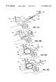
- FIG. 13Ais a perspective view of a polyhedral Type IA inflatable retraction device fitted with a suction skirt according to the invention
- FIG. 13Bis vertical cross section, along the line 2 — 2 in FIG. 1, of a polyhedral Type IA inflatable retraction device fitted with a suction skirt according to the invention;
- FIG. 14Ais a longitudinal cross sectional elevational view of a body illustrating the use according to the invention of a retraction device according to the invention in the abdomen to retract the bowel to gain anterior access to the intravertebral discs, the aorta, or the kidneys for treatment or observation.
- FIG. 14Bis a transverse cross sectional elevational view of a body illustrating the use according to the invention of a retraction device according to the invention in the abdomen to retract the bowel to gain anterior access to the intravertebral discs, the aorta, or the kidneys for treatment or observation.
- FIG. 15is a transverse cross sectional plan view of the chest illustrating the use according to the invention of a retraction device according to the invention to retract the pericardium from the heart to gain access to the surface of the heart for treatment or observation.
- FIG. 16Ais a transverse cross sectional elevational view of the chest illustrating the use according to the invention of a retraction device according to the invention to retract the lung away from the pleura to gain access to the surface of the lung for treatment or observation.
- FIG. 16Bis a transverse cross sectional plan view of the chest illustrating the use according to the invention of a retraction device according to the invention to retract the lung away from the pleura, part of the lung entering the main chamber of the retraction device for treatment or observation.
- FIG. 17is a longitudinal cross sectional elevational view of the chest illustrating the use according to the invention of a retraction device according to the invention to retract one lobe of the lung away from the rest of the lung to gain access to occlude part of the bronchial tree during a lobectomy.
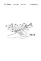
- FIG. 18is a longitudinal cross sectional elevational view of the abdomen illustrating the use according to the invention of a retraction device according to the invention to retract the liver to gain access to the gastroesophageal junction prior to sectioning the vagus nerve or to treating gastroesophageal reflux.
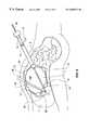
- FIG. 19is a longitudinal cross sectional elevational view of the head illustrating the use according to the invention of a retraction device according to the invention to retract the brain away from the dura mater to gain access to the brain for treatment or observation.
- FIG. 20Ais a transverse cross sectional elevational view of the lower abdomen illustrating the use according to the invention of a retraction device according to the invention between the abdominal wall and the peritoneum to retract the peritoneum to provide laparoscopic access to the site of a hernia without penetrating the peritoneum. A piece of mesh is shown being held in place over the site of the hernia by the retraction device.
- FIG. 20Bis a transverse cross sectional elevational view of the lower abdomen showing a retraction device according to the invention in its fully inflated condition holding a piece of mesh in position on the inside of the peritoneum over the site of the hernia.
- FIG. 21is a perspective view of a retraction device according to the invention with a piece of mesh attached to the outer surface of the main envelope.
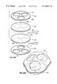
- FIG. 22Ais an exploded perspective view of the components of a polygonal Type IA retraction device illustrating the construction of such a device according to the invention.
- FIG. 22Bis a plan view of the additional envelope blank of a polygonal Type IA retraction device.
- FIG. 23Ais a perspective view of the additional envelope blank of a polygonal Type IA retraction device showing how a suction skirt according to the invention is formed from the additional envelope blank.
- FIG. 23Bis a plan view of the additional envelope blank of a polygonal Type IA retraction device showing how a suction skirt according to the invention is formed from the additional envelope blank.
- FIG. 24Ais an exploded perspective view of the components of a flat Type IA retraction device illustrating the construction of such a device according to the invention.
- FIG. 24Bis a perspective view of the assembled and inflated flat Type IA retraction device.
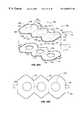
- FIG. 25Ais a perspective view of an inflated triangular prism-shaped Type IA retraction device according to the invention.
- FIG. 25Bis a vertical cross sectional view of an inflated the assembled triangular prism-shaped Type IA retraction device according to the invention along the line 25 B— 25 B in FIG. 25 A.
- FIG. 25Cis an exploded perspective view of the components of a triangular prism-shaped Type IA retraction device illustrating the construction of such a device according to the invention.
- FIG. 25Dis a plan view of the additional envelope blank of a triangular prism-shaped Type IA retraction device according to the invention.
- FIG. 26is an exploded perspective view of the components of a polygonal Type II retraction device illustrating the construction of such a device according to the invention.
- FIG. 27is an exploded perspective view of the components of a substantially hemispherical Type IA retraction device illustrating the construction of such device according to the invention.
- FIG. 28is a cross sectional view of a substantially hemispherical Type IA retraction device.
- FIGS. 1, 2 , and 3show perspective, and vertical and horizontal cross sectional views, respectively, of a first embodiment 1 of a retraction device according to the invention.
- This type of retraction devicehas an additional inflatable chamber and will be designated as a Type I retraction device.
- the Type I retraction device shown in FIGS. 1, 2 , and 3 with a segmented additional chamberwill be designated a Type IA retraction device.
- the retraction deviceis shown in its inflated condition.
- the retraction device 1comprises a main envelope 6 enclosing a main inflatable chamber 11 .
- the main envelope 6is made of a relatively inelastic and tough film of a plastic such as Mylar®, polyethylene, or polyurethane.
- the preferred material for the main envelope 6is a polyethylene and nylon composite.
- the thickness of the main envelope 6is typically from 0.5 to 5 mils (13 to 130 microns).
- the proximal end of a main inflation tube 16is sealed into the main envelope 6 .
- the main inflation tube 16allows an inflation gas to pass into and out of the main chamber 11 .
- the inflation gasis typically air, nitrogen or carbon dioxide, although other suitable gases may be used.
- Typical inflation gas pressuresare in the range 0.3 to 0.7 pounds per square inch (psi) (0.21 to 0.48 kPa), the preferred pressure being 0.5 psi (0.35 kPa).
- the main inflation tube 16is provided with a port 51 on its distal end, through which endoscopes and/or surgical instruments can be passed into the main chamber 11 .
- the port 51allows the inflation pressure of the main chamber 11 to be maintained when surgical instruments are passed through the port.
- the main envelope 6 of the Type IA retraction deviceis a polyhedral structure constructed from two segmented, substantially flat pieces of plastic film, which gives the retraction device a substantially polyhedral shape.
- two non-segmented, substantially flat pieces of plastic filmcan be used to make a relatively flat Type IA retraction device.
- the retraction devicecan be constructed from curved pieces of plastic film, which gives the retraction device a substantially spherical, spheroidal, or ellipsoidal shape.
- the size of retraction devices according to the inventioncan range from about 2′′ (50 mm) wide by about 0.5′′ (12 mm) high, for use inside the pericardium, to 10′′-14′′ (250-350 mm) wide by 4′′-8′′ (100-200 mm) high, for use in the abdominal cavity.
- the size of retraction device required for a given applicationdepends on the application and the size of the patient.
- the additional envelope 21is made from a film of the same thickness of the same plastic as the main envelope 6 .
- the periphery 26 of the additional envelope 21is attached to the surface of the main envelope 6 .
- the additional envelope 21has a segmented shape such that, when its periphery 26 is attached to the main envelope 6 , and the additional chamber 31 formed between the outside of the main envelope 6 and the inside of the additional envelope 21 is inflated, the additional chamber 31 forms a cage structure inside or outside the main chamber 11 , as shown in the figures.
- the cage structureis preferably formed on the faces of the polyhedron.
- the parts of the main envelope 6 that do not form part of the wall of the additional chamber 31provide a plurality of windows 46 that can be punctured to provide access for surgical instruments into and out of the main chamber 11 .
- the additional envelope 21is attached, preferably to the outer surface of the main envelope 6 , by welding along the periphery 26 of the additional envelope; alternatively, an adhesive may be applied to the periphery 26 of the additional envelope 21 , and the additional envelope 21 brought into contact with the main envelope 6 .
- Other methods that produce a flexible, gas-tight seal between the periphery 26 of the additional envelope 21 and the main envelope 6may also be used.
- the additional inflation tube 41allows an inflation gas to pass into and out of the additional chamber 31 .
- the inflation gasis typically air, nitrogen or carbon dioxide, although other suitable gases may be used. Typical inflation gas pressures are in the range 4 to 6 psi (2.8 to 4.1 kPa), the preferred pressure being 5 psi (3.5 kPa).
- the inflation gas pressure in the additional chamberis considerably higher than that in the main chamber to enable the additional chamber to exert sufficient force to keep already retracted organs in their retracted state despite the much smaller surface area of the additional chamber.
- the main inflation tube 16is sealed through the additional envelope 21 .
- the main inflation tube 16 and the additional inflation tube 41are contained within an inflation tube shield 61 , which forms a gas-tight seal with the retraction device.
- the outer wall of the inflation tube shield 61forms a gas-tight seal with the trocar or sheath through which it passes into the body cavity.
- the inflation tube shield 61can be a separate component.
- an extrusioncan provide the inflation tube shield 61 , the main inflation tube 16 and the additional inflation tube 41 in a unitary structure.
- the basic embodiment of a Type I retraction devicehas a single additional chamber 31 .
- additional chamber 31is divided into a plurality of sub-chambers (not shown).
- the sub-chambersare isolated from one another, so that if one or more of them is accidentally punctured while the retraction device is in use, deflation of all of the retraction device can be avoided.
- Each sub-chambercan be equipped with its own additional inflation tube.
- each sub-chambercan be connected to an inflation manifold (not shown) through a non-return valve (not shown). This arrangement requires that each sub-chamber be deliberately punctured to deflate the retraction device in preparation for withdrawing the retraction device from the body at the end of the treatment procedure.
- the additional envelope 21may be attached to the inner surface of the main envelope 6 .
- the main inflation tube 16passes through the additional chamber and forms a gas-tight seal with the additional envelope 21 in addition to the main envelope 6 .
- the additional envelope 21need not be segmented.
- the additional chamber 31is formed by attaching the additional envelope 21 to the main envelope 6 , the line of attachment forming the periphery of the cage structure of the additional chamber 31 .
- each window 46comprises a double thickness of film. This makes it somewhat more difficult to cut an aperture in a window.
- neither the main envelope 6 nor the additional envelope 21are segmented.
- the additional envelope 21has a number of holes cut in it.
- the additional chamber 31is formed by attaching the periphery of each hole in the additional envelope 21 to the main envelope 6 .
- FIGS. 25A, 25 B, 25 C, and 25 Dshow a Type IA retraction device in the shape of a triangular prism particularly suitable for use in the upper abdomen.
- the main envelope 6 and the additional envelope 21are serrated rectangles, as shown in FIGS. 25C and 25D.
- the additional envelopehas three large holes cut in it.
- the additional chamber 31is formed by attaching the periphery of each hole in the additional envelope 21 to the main envelope 6 . Opposite ends of the long axis of the rectangle and the serrations are joined together to form the triangular structure.
- All embodiments of the Type IA retraction devicemay be provided with tabs 56 on the inside the main envelope in accordance with a further aspect of the invention, as shown in FIGS. 2 and 3.
- the tabs 56may be separate components attached to the inside of the main envelope 6 by welding, an adhesive, or some other suitable method.
- the tabs 56can be an integral part of the main envelope 6 suitably extended into the main chamber 11 .
- Tabs 56provide points inside the main chamber 11 that can be gripped by a suitable gripping tool (not shown) inserted into main chamber 11 through the main inflation tube 16 .
- the gripping toolallows the inflated retraction device to be manipulated to change its position so that, for instance, one of its windows can be aligned with the organ or tissue to be treated or observed. Partially deflating the inflated retraction device makes repositioning easier.
- the word “organ”will be used to mean an organ or a tissue that is retracted by the retraction device.
- the word “treat”will be used to mean both treat and observe, and the word “treatment” will be used to mean both treatment and observation.
- the word “tissue” or the phrase “tissue to be treated”will both be used to mean the organ or the tissue that is treated through or inside the retraction device.
- FIGS. 4A through 4Dshow a cross sectional elevational view of the abdomen A to illustrate the method by which a Type IA retraction device according to the invention is inserted into the body and used to retract an organ within the body to gain access to treat a tissue.
- the retraction deviceis inserted into the abdomen A and is used to retract an organ, the bowel B, to gain access to treat a tissue, the gall bladder GB. Similar methods are used to insert a retraction device according to the invention into other parts of the body.
- Inflatable retraction device 1is supplied in a collapsed state, as shown in FIG. 4A, in which it is tightly packaged in a configuration that makes it essentially a linear extension of the inflation tube shield 61 .
- the retraction device 1is packed so that when pressure is applied to the main inflation tube 16 , the retraction device 1 deploys without tangling.
- the packaged retraction devicewill fit through an insertion tube (usually a trocar tube) of between 3 and 20 mm (0.12′′-0.8′′) in diameter, a typical diameter being 14 mm (0.55′′).
- the retraction device 1is retained in its collapsed state by the sleeve 100 which, in turn, is held together by one-pull lacing 105 .
- the sleeve 100can be fitted with a tear-off strip (not shown). Pulling on the thread 125 detaches the one-pull lacing 105 or the tear-off strip from the sleeve 100 , releasing the collapsed retraction device 1 .
- the sleeve 100can be provided with suitable markings 115 to enable its orientation to be determined and, if necessary, adjusted, after insertion into the body and before inflation.
- the abdomen APrior to starting the procedure, the abdomen A may be lifted to provide additional working space by gas insufflation, or by one of the mechanical devices disclosed in U.S. patent application Ser. No. 706,781, of which application this application is a Continuation-in-Part.
- the insufflated condition of the abdomen Ais indicated by the broken line A′.
- a small incisionis made in the skin of the abdomen A and a trocar (not shown) and trocar tube 120 are inserted into the incision and are driven through the wall of the abdomen A.
- the trocaris withdrawn.
- a second small incisionis made in the skin of the abdomen A and a trocar (not shown) and trocar tube 122 are inserted into the incision and driven through the wall of the abdomen.
- the trocaris withdrawn and an endoscope 110 is inserted into the trocar tube 122 .
- the second incisionis located so that the endoscope 110 can observe the intended placement site of the retraction device 1 .
- a small endoscope(not shown), preferably about 2 mm (0.1′′) in diameter, may be attached to the collapsed retraction device so that the location of the retraction device inside the abdomen may be determined.
- the endoscope 110is not used, and the second incision need not be made.
- the collapsed retraction device 1is threaded, with the aid of its inflation tube shield 61 , through the trocar tube 120 into the abdominal cavity AC, as shown in FIG. 4B, and manipulated into its correct position.
- the position of collapsed retraction device 1 in the abdominal cavity ACis observed through the endoscope 110 : the markings 115 enable the orientation of retraction device 1 to be determined and adjusted if necessary.
- the position of the collapsed retraction deviceis determined by means of the small endoscope (not shown) attached to the retraction device.
- the thread 125is then pulled to release the sleeve 100 from around collapsed retraction device 1 , and the sleeve 101 is withdrawn from the abdominal cavity AC through the trocar tube 120 by means of the thread 125 .
- the main inflation tube 16is connected to a source of inflation gas (not shown) and the gas supply is slowly turned on to inflate the main chamber 11 .
- the retraction device 1slowly expands, as shown in FIG. 4C, progressively displacing the bowel B as its size increases.
- the retraction device 1presents a relatively large surface area to the bowel B, and thus displaces the bowel B gently, progressively, and without trauma.
- the main chamber of the retraction deviceis capable of exerting the force necessary to effect the displacement the bowel B.
- the retraction device 1Once the retraction device 1 has reached its fully-inflated condition, its position is checked by viewing it through the endoscope 110 and/or an endoscope 110 (FIG. 4E) inserted into its main chamber 11 via the main inflation tube 16 and the port 51 .
- an endoscope 110 a(FIG. 4E) may be inserted into the main chamber 11 via the main inflation tube 16 prior to or during inflation, so that observation may be-made through the balloon before, during, and/or after inflation of the balloon.
- the port 51prevents loss of inflation pressure of the main chamber 11 when the endoscope extends through the port.
- the ability to observe (through the balloon) the area surrounding the balloonassists the user in positioning of the balloon and also provides visualization of the work area located outside the balloon as the surgical procedure is being performed.
- the tissue to be treatedmust be covered by one of the windows 46 of retraction device 1 .
- the inflation gas pressureis reduced slightly to partially deflate retraction device 1 .
- a suitable gripping toolis passed through the port 51 and the main inflation tube 16 into the interior of the retraction device 1 , to grip one of the tabs 56 (FIGS. 2 and 3 ).
- the gripping toolis manipulated to correct the positioning error while the position of the retraction device 1 is observed through the endoscope 110 or the endoscope 110 a (FIG. 4E) in the main chamber 11 .
- the main chamber 11 of the retraction device 1is reinflated by means of the main inflation tube 16 .
- the additional inflation tube 41is connected to a source of inflation gas (not shown) and the additional chamber 31 is inflated to the required pressure, as shown in FIG. 4 D.
- the source of inflation pressurecan be removed from the main chamber 11 and the main inflation tube 16 .
- the port 51can be removed from the main inflation tube 16 since a gas-tight seal is no longer required around instruments inserted into the main inflation tube 16 , the main chamber 11 now being at atmospheric pressure.
- a cutting instrument 52is then passed through the main inflation tube 16 into the main chamber 11 to cut a suitable aperture 54 in the window 46 that covers of the tissue to be treated, as shown in FIG. 5 .
- an additional puncturemay be made in the abdominal wall and a cutting instrument 62 passed through this puncture to cut an aperture 54 A in a window 58 to gain access to the main cavity 11 , and thence to cut a suitable aperture 54 in the window 46 .
- the aperture 54provides an access to the tissue to be treated; for example, the gall bladder GB.
- the aperture 54may simply be a cut in the window 46 , or all or part of the window 46 may be removed to provide the aperture 54 .
- an alternative way of passing instruments into the main chamber 11is to make at least one further incision in the body wall, the further incision being made in a location adjacent a further window 58 of the retraction device, as shown in FIG. 5.
- a trocar (not shown) with tube 60is inserted into the further incision and is driven through the body wall to pierce the further window 58 .
- the trocaris withdrawn leaving the trocar tube 60 in place.
- Instruments, e.g., instrument 62are then inserted into the retraction device as required through the trocar tube 60 and the further window 58 .
- FIG. 5additionally shows the retraction device 1 in place in the abdominal cavity AC in its fully inflated form.
- the main chamber 11is not pressurized; the shape of the retraction device is maintained by the inflated additional chamber 31 .
- retraction device 1was placed before inflation such that when the main chamber 11 was inflated, the expansion of the retraction device 1 displaced the bowel B to the right of the drawing and lifted the liver L upwards to expose the tissue to be treated, i.e., the gall bladder GB.
- the additional chamber 31is disconnected from the source of inflation pressure and the pressure in the additional chamber 31 is released to collapse the retraction device. Collapsing the retraction device is assisted by connecting the additional inflation tube 41 to a vacuum line (not shown) to evacuate the additional chamber 31 .
- a vacuum linenot shown
- FIG. 6shows an alternative embodiment 201 of a retraction device that maintains its shape while allowing treatment to be carried out working through or inside it.
- the alternative embodimentlacks the second inflatable chamber of the Type I embodiment shown in FIGS. 1 through 5, and has only a main envelope 206 enclosing a main chamber 211 .
- the single chamber embodiment of the retraction devicewill be designated as a Type II retraction device.
- the main chamber 211remains inflated throughout the treatment process, access to the tissue to be treated being provided by an elastomeric window 261 attached to the main envelope 206 .
- the elastomeric window 261is self-sealing and maintains inflation pressure in the main chamber 211 by forming a substantially gas-tight seal around instruments passed through it.
- the elastomeric window 261also forms a substantially gas-tight seal around the tissue to be treated if the tissue to be treated is pulled through the elastomeric window 261 into the main chamber 211 for treatment.
- the main envelope 206is made of a relatively inelastic and tough film of a plastic such as Mylar®, polyethylene, or polyurethane.
- the preferred material for the main envelopeis a polyethylene and nylon composite.
- the thickness of the main envelope 206is typically from 0.5 to 5 mils (13 to 130 microns).
- the proximal end of a main inflation tube 216is sealed into the main envelope 206 .
- the main inflation tube 216allows an inflation gas to pass into and out of the main chamber 211 .
- the inflation gasis typically air, nitrogen or carbon dioxide, although other suitable gases may be used. Typical inflation gas pressures are in the range 0.3 to 0.7 psi (0.21 to 0.48 Pa), the preferred pressure being 0.5 psi (0.35 kPa).
- the main inflation tube 216is provided with a port 251 on its distal end, through which endoscopes and other surgical instruments can be passed into the main chamber 211 .
- the port 251provides a gas-tight seal around instruments passed through it and allows inflation pressure to be maintained in the main chamber 211 with instruments present.
- the main envelope 206 of the Type II retraction device shown in FIG. 6is a polyhedral structure constructed from two segmented, substantially flat pieces of plastic film, which gives the retraction device a substantially polyhedral shape.
- two non-segmented substantially flat pieces of plastic filmcan be used to make a relatively flat Type II retraction device.
- the retraction devicecan be constructed from curved pieces of plastic film, which gives the retraction device a substantially spherical or spheroidal shape.
- Type II retraction devicescan range from about 2′′ (50 mm) wide by about 0.5′′ (12 mm) high, for instance for use inside the pericardium, to 10′′-14′′ (250-350 mm) wide by 4′′-8′′ (100-200 mm) high, for use in the abdominal cavity.
- the size of retraction device required for a given applicationdepends on the application and the size of the patient.
- the lack of a additional chamber in the retraction device 201 shown in FIG. 6makes orientation less critical. If the main envelope 206 is constructed from one or two curved pieces of film, orientation is particularly uncritical. If the main envelope 206 is a polyhedral structure having a number of faces, some orientation is required because the tissue to be treated must be substantially centered on one of the faces.
- the retraction device 201can be provided with tabs 256 on the inside the main envelope 206 . Tabs 256 may be separate components attached to the inside of the main envelope 206 by welding, an adhesive, or some other suitable method. Alternatively, tabs 256 can be an integral part of the main envelope 206 suitably extended into the main chamber 211 .
- Tabs 256provide points on the inside of the main chamber 211 that can be gripped by a suitable gripping tool (not shown) inserted into main chamber 211 through the inflation tube 216 and port 251 .
- the gripping toolallows the inflated retraction device 201 to be manipulated to change its position so that the desired point on the tissue to be treated can be substantially centered on one of its faces. Partially deflating the inflated retraction device makes repositioning easier.
- the elastomeric window 261is installed on the inside of the main envelope 206 after the retraction device 201 has been placed in the body and inflated.
- the elastomeric window 261is shown in FIG. 7 and comprises a flat piece 266 of a film of an elastomeric material such as latex or silicone rubber about 0.5′′ to 1.5′′ (12 to 37 mm) in diameter.
- the periphery of the elastomeric film 266is attached by means of a suitable adhesive, such as an acrylic cement or a silicone adhesive to one of the flat faces of a ring 271 having a square or rectangular cross section.
- the ring 271is circular or elliptical in shape and is of a springy material such as polyethylene or stainless steel, so that will regain its circular or elliptical shape after being compressed across one of its diameters to enable it to be passed through the inflation tube 216 .
- the other flat face 276 of the ring 271is coated with an adhesive.
- a pressure-sensitive adhesivesuch as a contact rubber adhesive may be used.
- a hot-melt adhesive of the type used in woodworking glue gunsis used. If a hot-melt adhesive is used, a heating element 281 , made of a suitable resistance wire, such as Nichrome, is inserted into a narrow groove in the face 276 of the ring 271 to which the adhesive is applied. Suitable electrical leads 291 are connected to the heating element 281 .
- the elastomeric windowBefore it can be inserted into the retraction device 201 , the elastomeric window must be wrapped across one of its diameters to reduce its width so that it can pass through the main inflation tube 216 , as shown in FIG. 8.
- a one-pull lacing arrangement 205or a sleeve with a tear strip (not shown) can be used. Wrapped elastomeric window 261 is attached to a manipulation rod 286 for insertion into the retraction device. Also attached to the manipulation rod is the thread 225 to release the one-pull lacing 205 or the tear strip (not shown) and, if a temperature-sensitive adhesive is used, the electrical leads 291 for the heating element 281 (FIG. 7 ).
- the wrapped elastomeric window 261 on the end of the manipulating rod 286is passed through the port 251 and the main inflation tube 216 into the main chamber 211 .
- the lacing 205 or tear-stripis released, which allows the elastomeric window 261 to resume its circular shape.
- the elastomeric window 261is then manipulated to bring it into contact with the main envelope 206 such that the elastomeric window 261 covers the tissue to be treated. If a pressure-sensitive adhesive is used, the face 276 of the elastomeric window is pushed against the main envelope 206 to affix the elastomeric window 261 in place.
- the face 276 of the elastomeric windowis placed against the main envelope 206 and a suitable source of electric current (not shown) is applied to the electrical leads 291 for the time required to melt the adhesive and affix the elastomeric window 261 to the main envelope 206 .
- the manipulating rod 286is detached from it and withdrawn from the main chamber 211 .
- a suitable cutting instrument 252is passed through the port 251 and the main inflation tube 216 into the main chamber 211 and through the elastomeric window 261 , as shown in FIG. 6 .
- the elastomeric window 261forms a gas-tight seal around the cutting instrument 252 , and re-seals itself after the cutting instrument 252 is withdrawn.
- the cutting instrument 252is used to cut an aperture in the part 296 of the main envelope 206 that is covered by the elastomeric window 261 .
- the part 296 of the main envelope 206is shown by shading in FIG.
- the aperture 254may simply be a cut in the part 296 of the envelope 206 , or all or part of the part 296 of the envelope 206 may be removed to provide the aperture 254 .
- Procedures that are carried out using instruments passed through the elastomeric window 261require removing more of the part 296 of the envelope 206 than procedures in which the tissue to be treated enters the retraction device through the aperture 254 and the elastomeric window 261 .
- the elastomeric window 261forms a seal around the tissue and isolates it from the body outside the retraction device.
- the treatment procedureis then carried out by inserting instruments through the port 251 and the main inflation tube 216 into the main chamber 211 and either working through the elastomeric window 261 or working on the tissue to be treated inside the cavity 211 .
- the retraction device 201is inserted into the abdomen using a procedure similar to that used to insert a Type IA retraction device.
- Inflatable retraction device 201is supplied in a collapsed state, as shown in FIG. 10A, in which it is tightly packaged in a configuration that makes it essentially a linear extension of the main inflation tube 216 .
- the retraction device 201is packed so that when inflation pressure is applied to the main inflation tube 216 , retraction device 201 deploys without tangling.
- the packaged retraction devicewill fit through an insertion tube of between 3 and 20 mm (0.12′′-0.8′′) in diameter, a typical diameter being 14 mm (0.55′′).
- the retraction device 201is retained in its collapsed state by a sleeve 100 which, in turn, is held together by one-pull lacing 105 or a tear strip (not shown).
- the sleeve 100can be provided with suitable markings 115 to enable its orientation to be determined and, if necessary, adjusted, after insertion into the abdomen and before inflation.
- the abdomen APrior to inserting the retraction device, the abdomen A may be lifted to provide additional working space by gas insufflation, or by one of the mechanical devices disclosed in U.S. patent application Ser. No. 706,781, of which application this application is a Continuation-in-Part.
- the insufflated state of the abdomen Ais indicated by the broken line A′.
- a small incisionis made in the skin of the abdomen A and a trocar (not shown) and trocar tube 120 are inserted into the incision and are driven through the wall of the abdomen A.
- the trocaris withdrawn.
- a second small incisionis made in the skin of the abdomen A and a trocar (not shown) and trocar tube 122 are inserted into the incision and driven through the wall of the abdomen.
- the trocaris withdrawn and an endoscope 110 is inserted into the trocar tube 122 .
- the second incisionis located so that the endoscope 110 can observe the intended placement site of the retraction device 1 .
- a small endoscope(not shown), preferably about 2 mm (0.14′′) in diameter, may be attached to the collapsed retraction device so that the location of the retraction device inside the abdomen may be determined.
- the endoscope 110is not used, and the second incision need not be made.
- the collapsed retraction device 201is threaded, with the aid of its main inflation tube 216 , through the trocar tube 120 into the abdomen A, and manipulated into its correct position.
- the position of collapsed retraction device 201is observed through the endoscope 110 : the markings 115 enable the orientation of the retraction device to be determined and adjusted if necessary.
- the position of the collapsed retraction deviceis determined by means of the small endoscope (not shown) attached to the retraction device.
- the thread 125is then pulled to release the sleeve 100 from around the collapsed retraction device 201 , as shown in FIG. 10B, and the sleeve 100 is withdrawn from the abdominal cavity AC through the trocar tube 120 by means of the thread 125 .
- the main inflation tube 216is connected to a source of inflation gas (not shown).
- the inflation gas pressureis slowly increased to inflate the main chamber 211 .
- the retraction device 201slowly expands, progressively displacing the bowel B as its size increases, as shown in FIG. 10 C. Throughout the expansion process, the retraction device 201 presents a relatively large surface area to the bowel B, and thus displaces the bowel gently, progressively, and without trauma. Although the retraction device 201 retracts the bowel B gently, the main chamber of the retraction device 201 is capable of exerting the force necessary to effect the displacement of the bowel.
- retraction device 201Once retraction device 201 has reached its fully-inflated condition, its position is checked by viewing it through either the endoscope 110 and/or an endoscope (not shown) inserted into the main chamber 211 of the retraction device 201 via the port 251 and the main inflation tube 216 .
- the tissue to be treatedshould be in contact with the main envelope 206 and lie substantially directly in line with the main inflation tube 216 . Further, if the retraction device is a polyhedron, the tissue to be treated should be substantially centered in one of its faces.
- the position of the retraction device 201can be adjusted by gripping one or more of the tabs 256 with a suitable gripping tool (not shown), as described above.
- FIG. 10Dshows the retraction device 201 in its fully inflated state with the elastomeric window 261 installed, and the instrument 252 passed through the elastomeric window 261 and the aperture 254 in the main envelope 206 to treat the tissue to be treated, the gall bladder, GB.
- the main chamber 211is disconnected from the source of inflation pressure and the pressure in the main chamber 211 is released to collapse the retraction device. Collapsing the retraction device is assisted by connecting the main inflation tube 216 to a vacuum line (not shown) to evacuate the main chamber 211 .
- the retraction device 201is withdrawn from the abdominal cavity through the opening in the abdominal wall that remains after withdrawing the trocar tube 120 .
- the elastomeric window 261is sufficiently flexible to be withdrawn through the opening in the abdominal wall along with the retraction device 201 . The openings in the abdominal wall are then closed in the normal way.
- FIGS. 11A, 11 B, and 11 CA further embodiment of the invention, which is a variation on the Type I retraction device, designated Type IB, is shown in FIGS. 11A, 11 B, and 11 C.
- This variationhas the advantage of providing two large, flat windows, but has the disadvantage that it does not allow any access to tissues lying to the side of the retraction device.
- the retraction device 301 shown in FIGS. 11A and 11Bis substantially cylindrical in shape.
- a stack of one or more toroidal chambersforms the additional chamber 331 .
- the example shown in FIGS. 11A and 11Bhas 3 toroidal chambers 325 , 327 and 329 .
- a single chamber having sidewalls 333 that are tacked togethercan be used for the additional chamber 331 .
- the tacked sidewallsform an enclosure having a height that is considerably greater than its width.
- the diaphragms 307 and 309cover the top and bottom, respectively, of the retraction device 301 .
- the diaphragms 307 and 309together the inner walls of the toroidal chambers 325 , 327 , and 329 , form the main chamber 311 .
- the main inflation tube 316is sealed into the main chamber 311 and allows the main chamber to be inflated.
- the additional inflation tube 341is sealed into the additional chamber 331 . If more than one toroidal chamber is used to provide the additional chamber, the toroidal chambers may be interconnected and a single additional inflation tube 341 used, or each toroidal chamber may be provided with its own additional inflation tube (not shown). The latter approach prevents the retraction device 301 from collapsing completely if one of the toroidal chambers 325 , 327 , or 329 is accidentally punctured, and also allows the height of the retraction device to be adjusted by selectively inflating the toroidal chambers 325 , 327 , or 329 .
- the Type IB retraction device shown in FIGS. 12 and 13is constructed from similar materials to the Type IA retraction device, and may be fitted with tabs 356 , similar to tabs 56 in the Type IA retraction device, to enable it to be properly positioned after inflation.
- a similar procedureis used to deploy the Type IB retraction device in the body as is used to deploy the Type IA retraction device, and will not be described in detail.
- a similar inflation procedureis used, except that the additional chamber may be inflated at least partially at the same time as the first cavity is inflated.
- the Type IB retraction devicedepends more for its shape on the additional chamber than the Type IA retraction device. Hence, at least partial inflation of the additional chamber is necessary to enable the retraction device to displace organs to the side of the retraction device. Inflation pressures similar to those used for the Type IA retraction device are used.
- Treatment procedures using the Type IB retraction deviceare similar to those using the Type IA retraction device, except that the Type IB retraction device does not provide access to tissues to the side of the device.
- the diaphragms 307 and 309are analogous to the windows 46 (FIG. 1) of the Type IA retraction device. Either or both of the windows provided by the diaphragms 307 and 309 may be pierced to provide apertures though which treatment may be carried out, or through which the tissue to be treated may be brought into the retraction device for treatment, or through which instruments may be passed into and out of the main chamber 311 .
- a further aspect of the inventionis the provision in a retraction device according to the invention, of one or more flexible sheaths to interconnect the main chamber of the retraction device and the outside of the body into which the retraction device is inserted.
- the flexible sheathprovides a tract through the body wall that allows additional surgical instruments or endoscopes to be introduced into the main chamber of the retraction device, and/or allows tissue and the like to be removed.
- the flexible sheathis attached to a window of a Type I retraction device or to the main envelope of a Type II retraction device.
- FIG. 12Ashows a flexible sheath according to the invention attached to a window 46 of a Type IA retraction device 1 , which is shown as an example.
- a flexible sheath according to this aspect of the inventioncan also be used with Type IB and Type II retraction devices.
- the flexible sheath 3is substantially cylindrical in shape with a closed distal end 8 .
- the proximal end 13 of the flexible sheathis attached to the outer surface of the window 46 .
- the sidewall 18 of the flexible sheath 3is folded concertina-style when the retraction device is packaged, and remains folded after the retraction device has been inflated. After the retraction device 1 has been deployed in the body, as shown in FIG.
- a suitable pointed tool 23is fed into the main chamber 11 to pierce a hole 28 in the part of the window 46 that is covered by the flexible sheath 3 .
- the pointed tool 23is pushed through the hole 28 to engage with the distal end 8 of the flexible sheath 3 .
- the distal end 8is first pressed against the inner surface of the body wall W using the pointed tool 23 .
- the resulting bulge in the skin S on the outside of the bodyindicates where the flexible sheath 3 will emerge.
- a small incision 33is made in the skin S at that point.
- the flexible sheath 3is then driven by the pointed tool 23 through the body wall W to emerge through the incision 33 .
- the distal end 8 of the flexible sheath 3is then opened to provide access to the main chamber 11 .
- the flexible sheathdoes not have to be gas-tight in the manner of conventional trocar sheaths, and permits ordinary surgical instruments to be used.
- the flexible sheathis fitted with a gas-tight port similar to the port 251 (FIG. 6) before the distal end 8 is opened.
- FIG. 12CThe alternative embodiment of a flexible sheath 43 according to the invention, shown in FIG. 12C, is not initially attached to the retraction device.
- a Type IA retraction device 1is shown in FIG. 12C as an example.
- a flexible sheath according to this aspect of the inventioncan also be used with Type IB and Type II retraction devices.
- the flexible sheath 43comprises a cylindrical piece of flexible plastic 48 with a coaxial locking device 53 on its proximal end.
- the distal end of the flexible sheath for a Type II retraction devicemust be closed by a port (not shown) similar to the port 251 (FIG. 6) so that pressurization of the main cavity can be maintained after the flexible sheath 43 has been installed.
- the flexible sheath 43is installed after the retraction device 1 has been deployed in the body. A small incision 58 is made in the skin S of the body. The flexible sheath 43 is then driven through the body wall W by a sharp trocar point (not shown). The trocar point pierces a hole 63 in the window 46 of the retraction device 1 , and pushes the locking device 53 of the flexible sheath 43 through the hole 63 to engage the locking device 53 with the window 46 . When used with a Type II retraction device, the locking device 53 forms a gas-tight seal with the window 46 .
- a retraction device according to the inventionmay be fitted with a tubular suction skirt on the part of the retraction device that is lower-most when the retraction device is deployed in the body.
- FIGS. 13A and 13Bshow, as an example, a polygonal Type 1 A retraction device of the type used in the abdominal cavity.
- the suction skirt of this aspect of the inventioncan be used with other type I and type II retraction devices.
- suction skirt 12 on the bottom of the retraction deviceis connected to a suction line and removes such fluid during the treatment procedure, keeping the cavity clear of accumulated fluids.
- the suction skirtis a tubular appendage attached to the lower-most extremity of the retraction device.
- the suction skirtis formed from part of the additional envelope 21 around the bottom window 46 .
- the bottom or sides of the suction skirtis pierced with between six and twelve holes 17 .
- the suction skirtis about 1 ⁇ 4′′ (6.2 mm) in diameter, and the holes 17 are about 1 ⁇ 8′′ (3.1 mm) in diameter.
- the suction skirtis made of the polyethylene-nylon composite that is the preferred material for the main envelope 6 of the retraction device. This material is sufficiently resilient that a tubular structure made from it can retain its open cross section under a low vacuum.
- One end of the suction skirtis closed; the other is connected to a thin-wall polyethylene tube 22 that runs up the side of the retraction device to exit the body through the same incision as is used for the inflation tubes. If, as is shown in FIGS. 13A and 13B, the retraction device is used in an insufflated body cavity, the suction skirt tube 22 passes inside the inflation tube sheath 61 .
- the distal end of the suction skirt tube 22has attached to it a connector suitable for attaching to an operating room suction line.
- FIG. 14A method can be adapted to gain anterior access to the aorta, the kidneys, and other tissues that lie outside the peritoneum.
- FIG. 14Ashows a longitudinal cross section of the body; and
- FIG. 14Bshows a transverse cross section along the line 14 B— 14 B in FIG. 14 A.
- Anterior access to the spineis normally difficult due to the difficulty of retracting the overlying bowel using conventional laparoscopic retractors.
- a Type I or a Type II retraction deviceis used according to the invention to retract the bowel by forming a small incision 420 in the abdominal wall W and inserting a trocar (not shown) with trocar tube 430 into the incision 420 and driving the trocar into the abdominal cavity AC.
- the trocaris removed and the retraction device 401 is passed through the trocar tube 430 into the abdominal cavity AC in its contracted state with the aid of its inflation tube or inflation tube shield (the inflation tube shield 461 of a Type IA retraction device is shown).
- the main chamber 411 of the retraction device 401is inflated with a suitable inflation gas passed though inflation tube 416 .
- the relatively large surface area of the main chamber 411 of the retraction devicegently retracts the bowel 431 , either upwards or downwards, depending on the position of the disc to be treated.
- the positioning of the retraction deviceis checked and adjusted, if necessary, as previously described.
- a Type I retraction deviceIf a Type I retraction device is used, it must be positioned such that the disc that it is desired to treat is centered in one of its windows.
- the additional chamber 431is inflated, and the inflation gas pressure in the 411 main chamber is released.
- the inflated additional chambermaintains the shape of the retraction device.
- an elastomeric window(not shown) is installed, as previously described, on the inside of the main envelope in a position that will provide access to the disc to be treated.
- the main envelope 406 of both types of retraction devicecan then be pierced, and partially removed, if necessary. An incision is made in the peritoneum exposed by the retraction device to gain access to and to resect the disc to be treated.
- FIGS. 14A and 14Bshow instrument 452 passed from outside the body through the main inflation tube 416 into the main chamber 411 .
- the instrument 452passes out of the main chamber 411 through an aperture (not shown) pierced in the window 446 .
- the retraction deviceis deflated and removed from the body, and the small incisions in the abdominal wall repaired, as already described.
- FIG. 15shows a transverse cross section of the chest. Displacement of the pericardium allows the outer surface 413 of the heart 408 to be observed, and such procedures as endocardial mapping, ablation, transmyocardial revascularization, and defibrillation to be carried out. These procedures have until now been difficult to do laparoscopically because access to the surface of the heart 408 is obstructed by the pericardium 403 .
- a small puncture 418is made in the chest wall 423 and through the puncture 418 , a small incision 428 is made in the pericardium 403 .
- An introducer tube(not shown) is inserted to connect the pericardial cavity 453 to outside the patient.
- a retraction device 401 according to the inventionis inserted using its inflation tubes (the main inflation tube 416 is shown) through the introducer tube into the pericardial cavity 453 so that it rests between the surface 413 of the heart and the pericardium 403 .
- the retraction device 401is then released from its packing (not shown), as described above, and its main chamber 411 is inflated.
- the main envelope 406 of the retraction devicegently displaces the heart 408 from the pericardium 403 .
- the position of the retraction deviceis checked and, if necessary, adjusted.
- Type I retraction deviceIf a Type I retraction device is used, it must be positioned such that the part of the heart that it is desired to treat is centered in one of its windows. The additional chamber 431 is then inflated and the inflation pressure removed from the main chamber.
- an elastomeric windowis installed, as previously described, on the inside of the main envelope in a position that will provide access to the part of the heart to be treated.
- the introducer tube(not shown) can be withdrawn and the main inflation tube 416 used as a path for endoscopes and instruments to pass in to the main chamber of the retraction device.
- FIG. 15shows an endoscope 433 passed through the main inflation tube 416 to observe the outer surface 413 of the heart.
- FIG. 15also shows an instrument probe 438 that has been passed through the chest wall 423 to contact the surface 413 of the heart.
- the instrument probe 438is passed through the pericardium 403 and the main chamber 411 of the retraction device 401 , piercing a first window 443 and a second window 448 of the retraction device.
- the retraction deviceis withdrawn from the pericardial cavity, as already described, and the small incisions in the pericardium and the chest wall are repaired.
- FIG. 16shows a further procedure according to the invention in which a retraction device according to the invention is used in the pleural cavity to retract the lung from the pleura to allow observation and manipulation.
- FIG. 16Ashows a vertical cross sectional view of the chest and
- FIG. 16Bshows a transverse cross section along the line 16 B— 16 B in FIG. 16A.
- a small, oblate version of a Type I or Type II retraction device 401 according to the inventionis used to displace the lung 402 from the pleura 407 to allow resection of a lobe 412 of the lung 402 .
- a small incision 417is made in the chest wall 423 and, through the incision 417 , a trocar (not shown) is inserted to connect the pleural cavity 432 to outside the patient.
- the trocar point (not shown)is removed leaving the trocar tube (not shown) connecting the pleural cavity 432 to outside the patient.
- a retraction device 401 according to the inventionis inserted using its inflation tubes (inflation tube 416 is shown) through the trocar tube into the pleural cavity, so that it rests between the surface of the lung 402 and the pleura 407 .
- the retraction device 401is then released from its packing (not shown), as described above, and its main chamber 411 is inflated.
- the main envelope 406 of the retraction devicegently displaces the lung 402 from the pleura 407 .
- the position of the retraction deviceis checked and, if necessary, adjusted.
- a Type I retraction deviceIf a Type I retraction device is used, it must be positioned such that the part of the lung that it is desired to treat is centered in one of its windows. The additional chamber 431 is then inflated and the inflation pressure removed from the main chamber 411 .
- an elastomeric windowis installed, as previously described, on the inside of the main envelope in a position that will provide access to the part of the lung to be treated.
- the trocar tube(not shown) can be withdrawn and the main inflation tube 416 used as a path for endoscopes and instruments to pass to the inside of the retraction device.
- FIG. 16shows an endoscope 433 passed through the main inflation tube 416 into the main chamber of the retraction device 401 .
- the main inflation tube 416enters the main chamber 411 through a first window 443 .
- Part of a second window 448has been removed, as already described, to allow a part 437 of the lung 402 to enter the main chamber 411 of retraction device for treatment.
- a trocar tube 447passes through the chest wall 423 and enters the retraction device by piercing a third window 452 , and an instrument 442 is passed through the trocar tube 447 to section part of the lung 437 .
- the part of the window 448 that has not been removedforms a seal around the part 437 of the lung inside the retraction device, and prevents sectioned tissue from entering the pleural cavity.
- the retraction deviceis withdrawn from the pleural cavity, as already described, and the small incisions in the pleura and the chest wall are repaired.
- a retraction deviceis used to retract one lobe of a lung in a lobectomy. This is shown in FIG. 17, which shows a longitudinal cross section of the chest.
- the lobes of the lungoverlay one another: in performing a lobectomy, access to the hilar portion of the bronchial tree is required so that the branches of the bronchial tree feeding the lobe to be sectioned can be occluded.
- a Type IA or Type II retraction device 401 according to the inventionis used to displace the lobe 404 away from the rest of the lung 409 to provide access to the bronchial tree 414 .
- a small incision 419is made in the chest wall 423 , and through the incision 419 , a trocar (not shown) is inserted through the chest wall 423 and pleura 429 .
- the trocar (not shown)is removed and the trocar tube is maneuvered to place its distal end between the lobe 404 and the rest of the lung 409 .
- a retraction device 401 according to the inventionis inserted using its inflation tubes (inflation tube 416 is shown) through the trocar tube into position between the lobe 404 and the rest of the lung 409 .
- the retraction device 401is then released from its packing (not shown), as described above, and its main chamber 411 is inflated.
- the main envelope 406 of the retraction devicegently displaces the lobe 404 away from the rest of the lung 409 .
- the position of the retraction deviceis checked and, if necessary, adjusted.
- a Type I retraction deviceIf a Type I retraction device is used, it must be positioned such that the part of the bronchial tree that it is desired to occlude is centered in one of its windows. The additional chamber 431 is then inflated and the inflation pressure removed from the main chamber.
- a elastomeric window(not shown) is applied to the inside of the main chamber 411 in a position such that the part of the bronchial tree that it is desired to occlude can accessed through the elastomeric window.
- an apertureis cut in the main envelope 406 through which the procedure for occluding a part of the bronchial tree can be carried out using instruments, passed into the main chamber 411 through the inflation tube 416 . Additional instruments can be inserted into the main chamber through flexible sheaths (not shown) and/or, in a Type I retraction device, through apertures pierced in other windows (not shown) of the main envelope 406 .
- the retraction deviceis deflated and withdrawn, as already described, from between the lobe 404 and the rest o f the lung 409 . The procedure for sectioning the lobe is carried out before the small incisions in the pleura and the chest wall are repaired.
- FIG. 18An other procedure according to the invention is shown in FIG. 18 . It is necessary to gain access to the gastroesophageal junction between the stomach 405 and the esophagus 410 to be able to section the vagus nerve, or to treat gastroesophageal reflux.
- the gastroesophageal junctionis normally obscured by the liver 415 , which must be retracted provide access for treating this area.
- a Type I or Type II retraction device 401according to the invention is used to displace the liver 415 away from the esophagus 410 . According to the procedure, a small incision 420 is made in the abdominal wall 425 .
- a trocar (not shown) and trocar tube 440is inserted through the incision 420 and is driven through the abdominal wall 425 into the abdominal cavity AC and the trocar is removed.
- the trocar tubeis maneuvered to place its distal end between the liver 415 and the esophagus 410 .
- a retraction device 401 according to the inventionis inserted using its inflation tubes (inflation tube 416 is shown) through the trocar tube into position between the liver 415 and the esophagus 410 .
- the retraction device 401is then released from its packing (not shown), as described above, and its main chamber 411 is inflated.
- the main envelope 406 of the retraction devicegently displaces the liver 415 away from the esophagus 410 .
- the position of the retraction deviceis checked and, if necessary, adjusted.
- a Type I retraction deviceIf a Type I retraction device is used, it must be positioned such that the gastroesophageal junction is centered in one of its windows. The additional chamber 431 is then inflated and the inflation pressure removed from the main chamber.
- a elastomeric window(not shown) is applied to the inside of the main chamber 411 in a position such that the gastroesophageal junction can accessed through the elastomeric window.
- an apertureis cut in the main envelope 406 through which the treatment procedure can be carried out using instruments (e.g., instrument 452 ) passed into the main chamber 411 through at least the inflation tube 416 . Additionally or alternatively, instruments can be inserted into the main chamber 411 through flexible sheaths (not shown) and/or, in a Type I retraction device, through apertures pierced in other windows (not shown) in the main envelope 406 .
- the retraction deviceis deflated and withdrawn, as already described, from between the liver 415 and the esophagus 410 , the small incisions in abdominal wall are repaired.
- FIG. 19shows a vertical cross section of the head.
- a small, very oblate version of a Type I or Type II retraction device 401 according to the inventionis used in this procedure.
- a small incision 460is made in the skin of the head, and, working through the incision, a small hole 465 is drilled in the skull to provide access to the dura mater 455 .
- An incision 470is made in the dura mater to expose the surface of the brain 450 .
- a retraction device 401 according to the inventionis inserted using forceps through the incision 460 , the hole 465 , and the incision 470 into the skull between the surface of the brain 450 and the dura mater 455 .
- the retraction device 401is then released, as described above, from its packing (not shown), and its main chamber 411 is inflated.
- the main envelope 406 of the retraction devicegently displaces the brain 450 away from the dura mater 455 .
- the position of the retraction deviceis checked and, if necessary, adjusted.
- a Type I retraction deviceIf a Type I retraction device is used, it must be positioned such that part of the brain that it is desired to treat is centered in one of its windows. The additional chamber (not shown) is then inflated and the inflation pressure removed from the main chamber.
- a elastomeric window(not shown) is applied to the inside of the main chamber 411 in a position such that the part of the brain that it is desired to treat can be accessed through the elastomeric window.
- an apertureis cut in the main envelope 406 through which the treatment procedure can be carried out, using instruments passed into the main chamber 411 through the inflation tube 416 . Additionally or alternatively, instruments can be inserted into the main chamber, in a Type I retraction device, through apertures pierced in other windows ( 465 , 470 ) of the main envelope 406 .
- the retraction deviceis deflated and withdrawn, as already described, from between the brain 450 and the dura mater 455 . Finally, the small incisions in the dura mater and the scalp and the hole in the skull are repaired.
- FIG. 20Ashows a vertical cross section of the lower abdomen.
- a flat, substantially elliptical or rectangular Type IA or Type II retraction device 501 according to the inventionis used to retract the peritoneum 502 away from the abdominal wall 517 .
- a small incision 522is made in the abdominal wall 517 near the umbilicus 507 , and the layers of tissue are cut through as far as the peritoneum.
- a retraction device 501 according to the inventionis inserted using forceps through the incision 522 into position between the abdominal wall 517 and the peritoneum 502 .
- the retraction device 501is then released, as described above, from its packing (not shown), and its main chamber 511 is inflated.
- the main envelope 506 of the retraction devicespreads inferiorly towards the inguinal area, and gently displaces the peritoneum 502 back from the abdominal wall 517 .
- the position of the retraction deviceis checked and, if necessary, adjusted.
- a Type I retraction deviceIf a Type I retraction device is used, it must be positioned such that the site of the hernia is centered in one of its windows. The additional chamber 531 is then inflated and the inflation pressure removed from the main chamber.
- a elastomeric window(not shown) is applied to the inside of the main chamber 511 in a position such that the site of the hernia can be accessed through the elastomeric window.
- an apertureis cut in the main envelope 506 through which the treatment procedure can be carried out using instruments passed into the main chamber 511 through the inflation tube 516 .
- instrumentscan be inserted into the main chamber through flexible sheaths (not shown) and/or, in a Type I retraction device, through apertures (not shown) pierced in other windows of the main envelope 506 .
- the retraction deviceis deflated and withdrawn, as already described, from between the peritoneum 502 and the abdominal wall 517 and the small incision in the abdominal wall 517 is repaired.
- One known technique for repairing a herniais by suturing or stapling a fine mesh over the site of the hernia.
- the meshis preferably installed on the abdominal wall outside the peritoneum to prevent the mesh and its sutures or staples from irritating the bowel.
- Using conventional laparoscopic techniques to hold the mesh in place while it is cut to size and stapled in positionis a very difficult procedure.
- a piece of mesh 527is attached, for instance by a suitable adhesive applied to the perimeter of the piece of mesh, to substantially cover the window 532 of the retraction device 501 , as shown in FIG. 21 .
- the window 532is the window that will contact the site of the hernia 512 when the retraction device has been deployed.
- the retraction device with the meshis then packaged as previously described, and the retraction device is inserted between the peritoneum 502 and the abdominal cavity 517 and inflated, also as previously described. Inflation of the balloon causes flattening and/or expansion of the mesh into the condition shown in FIG. 21 .
- the position of the retraction device 501is then adjusted, using tabs 556 and a suitable gripping tool (not shown) to position the mesh-covered window so that the mesh 527 covers the site of the hernia 512 .
- the additional chamber 531is inflated and the inflation pressure removed from the main chamber.
- the retraction device 501holds the mesh 527 in place over the site of the hernia while the mesh is stapled in place and excess mesh is cut off.
- Part of the window 532is cut away, using a suitable tool inserted into the main chamber 511 through the inflation tube 516 , to expose the area of the mesh into which staples will be placed.
- the meshis stapled to the site of the hernia 512 using staples (not shown) inserted by means of a conventional laparoscopic stapler (not shown). More of the window 532 is then cut away and a suitable laparoscopic cutting tool is inserted into the main chamber 511 to cut the mesh around the stapled area. The excess mesh is removed when the retraction device is removed from the body, as previously described.
- a low irritation Dacron® meshis installed on the inside of the peritoneum, the retraction device with a piece of mesh covering one of its windows being inserted into the peritoneal cavity before the retraction device is inflated, as shown in FIG. 20 B.
- the meshis cut to the required size before it is attached to the window of the retraction device.
- the meshis attached to the window of the retraction device by one-pull lacing, and the thread for the one-pull lacing is fed through the main inflation tube. After the mesh has been correctly positioned and stapled in place, as previously described, the thread is pulled to release the one-pull lacing, which releases the mesh from the window of the retraction device. The retraction device is then withdrawn as previously described.
- This variationdoes not require the mesh to be cut to size after it has been stapled in place.
- FIGS. 22A and 22BThe construction according to the invention of a polygonal Type IA retraction device is illustrated in FIGS. 22A and 22B.
- the construction of a dodecahedral retraction deviceis illustrated.
- a dodecahedral retraction devicegives a good compromise between approximating a spherical or spheroidal shape, and complexity. Increasing the number of faces makes a shape that is more nearly spherical but is more complex to make.
- the additional chamber of a retraction device that is more nearly sphericalprovides more retraction force than the additional chamber of a polyhedral retraction device that is more nearly cubic.
- the main envelope and the additional envelope of the retraction deviceare both made of a relatively inelastic and tough film of a plastic such as Mylar®, polyethylene, or polyurethane.
- the preferred materialis a polyethylene and nylon composite.
- the thickness of the main envelopeis typically from 0.5 to 5 mils (13 to 130 microns).
- the additional envelopeis made from a film of the same thickness of the same plastic as the main envelope. However, in some applications it may be advantageous make the additional envelope from a film of a different thickness of the same plastic, or from a film of the same or a different thickness of a different plastic.
- Two segmented circular main envelope blanks 600 and 601 and two segmented circular additional envelope blanks 625 and 626are cut from a piece of film, preferably by die cutting.
- the main envelope blank 600 , the additional envelope blank 625 , and the formation of an envelope half from themwill now be described. A similar explanation applies to the main envelope blank 601 , the additional envelope blank 626 , and the formation of an envelope half from them.
- the number of segments in the two main envelope blanks 600 and 601determines the number of faces that the polyhedral retraction device will have.
- the main envelope blank 600has five segments 605 .
- the width and depth of the segments 605determines the shape of the retraction device: wide, shallow segments result is a relatively flat retraction device, whereas narrow, deep segments result in a relatively tall retraction device.
- the number of segments 630 in the additional envelope blank 625is preferably equal to the number of segments 605 of the main envelope blank 600 ; thus, the additional envelope blank 625 has five segments 630 to match the five segments 605 of the main envelope blank 600 .
- the shape of the segments 630is substantially the same as that of the segments 605 , except the parts of each segment 630 indicated by shading and the reference numeral 655 in FIG. 22B are cut away compared with the segment 605 in the main envelope blank.
- the cut away areas 655provide the windows 46 (FIG. 1) in the side of the retraction device. Each area 655 will therefore be called a side window area 655 .
- Another area 645 in the center of the additional envelope blank 625is cut away.
- the cut away area 645forms the window 46 (FIG. 1) in the top end or the bottom end of the retraction device, and will thus be called the end window area 645 .
- the end window areais shown with a circular shape in FIG. 22B; alternatively, it could have a polygonal shape.
- the side and end window areasare preferably cut in the same die-cutting operation in which the additional envelope is die cut from the plastic film.
- An envelope halfis made by laying the additional envelope blank 625 on the main envelope blank 600 such that the segments 630 coincide with the segments 605 .
- the broken line 650 in FIG. 22Aindicates the position of each side window area 655 when the additional envelope blank 625 is correctly positioned on the main envelope bank 600 .
- the periphery of each side window area 655 of the additional envelope blank 625is attached to the main envelope blank 600 , preferably by welding. Alternatively, a line of adhesive applied to the periphery of each side window area 655 can be used.
- the periphery of the end window area 645 in the additional envelope blank 625is also attached to the main envelope blank 600 , preferably by welding. Alternatively, a line of adhesive applied to the periphery of the end window area 645 can be used.
- the envelope halfis then given a 3-dimensional form by joining the edge 610 of each segment 605 in the main envelope blank 600 to the edge 615 of the adjacent segment, and by joining the edge 635 of each segment 630 in the additional envelope blank 625 to the edge 640 of the adjacent segment.
- the preferred method of joining in this step and the following steps involving joiningis overlap welding. Alternatively, butt welding or a line of a suitable adhesive can be used.
- the envelope halfmay be formed so that the additional envelope blank 625 is inside or outside the main envelope blank 600 . In the preferred embodiment, the additional envelope blank is inside the main envelope blank.
- a second envelope halfis made from the main envelope blank 601 and the additional envelope blank 626 , as described above.
- One of the two envelope halvesis then inverted relative to the other, and the two envelope halves are joined together with the periphery 620 in contact with the periphery 621 (main envelope) and the periphery 660 in contact with the periphery 661 (additional envelope).
- the peripheries of the envelope blanks on the insideare joined first.
- the envelope halvesare joined as follows: the peripheries 620 and 621 of the main envelope blanks 600 and 601 are joined first. A small part of the peripheries 620 and 621 of the main envelope blanks is left unjoined.
- the main inflation tube 616is a piece of polyethylene tubing with an outside diameter in the range of 2.5 to 19.5 mm (0.1′′ to 0.77′′) and of suitable length.
- the distal end of the main inflation tube 616is fitted with a port 651 that allows surgical instruments to be passed into the main inflation tube while maintaining inflation pressure in the main chamber of the retraction device.
- the port 651also includes a fitting (not shown) suitable for connecting the port to a source of inflation gas (not shown).
- the proximal end of the main inflation tube 616is inserted into the unjoined part of the peripheries 620 and 621 of the additional envelope blanks 600 and 601 and joining the periphery 620 to the periphery 621 is completed. Where the peripheries 620 and 621 contact the main inflation tube 616 , they are joined to the outer wall of the main inflation tube to form a gas-tight seal.
- the peripheries 660 and 661 of the outer envelope blanksi.e., the additional envelope blanks 625 and 626 , are then joined to one another and, where they contact the main inflation tube 616 , to the outer wall of the main inflation tube to form a gas-tight seal.
- a small part of the peripheries 660 and 661 of the additional envelope blanks 625 and 626is left unjoined.
- the additional inflation tube 641is a piece of polyethylene tubing with an outside diameter in the range of 2.5 to 5 mm (0.1′′ to 0.2′′) and of suitable length.
- the distal end of the additional inflation tube 641is fitted with a fitting (not shown) suitable for connecting it to a source of inflation gas (not shown).
- the proximal end of the additional inflation tube 641is inserted into the unjoined part of the peripheries 660 and 661 of the additional envelope blanks 625 and 626 , and joining the periphery 660 to the periphery 661 is completed. Where the peripheries 660 and 661 contact the additional inflation tube 641 , they are joined to the outer wall of the additional inflation tube to form a gas-tight seal.
- the peripheries 660 and 661 of the additional envelope blanks 625 and 626are joined to one another and to the outer wall of the main inflation tube 616 .
- the peripheries 620 and 621 of the main envelope blanks 600 and 601are then joined together, and to the outer wall of the main inflation tube 616 and to the outer wall of the additional inflation tube 641 .
- the main and additional inflation tubesmust be surrounded by an inflation tube shield.
- the additional envelope blanks for such a retraction deviceare cut to include an inflation tube seal 680 and 681 .
- the inflation tube sheath(not shown) is pushed over the main and additional inflation tubes after they have been sealed into the retraction device and the inflation tube seals are joined to one another, preferably by welding. Alternatively, a suitable adhesive can be used. Where the inflation tube seals 680 and 681 contact the inflation tube sheath, they are joined to the outer wall of the inflation tube shield to form a gas-tight seal.
- the above methodcan be adapted for use if a single extrusion is used to provide the main and additional inflation tubes and the inflation tube sheath.
- An alternative method of making a polygonal type IA retraction deviceis the same as the method just described, except that the additional envelope blanks 625 and 626 are cut with the same die as the main envelope blanks 600 and 601 .
- a main envelope blankis attached to an additional envelope blank by welding along the broken lines 650 and 665 (FIG. 22 A).
- a main envelope blankcan be attached to an additional envelope blank by a line of a suitable adhesive spread along the broken lines 650 and 665 .
- the envelope halvesare then formed and attached to one another using the method described above.
- the additional chamber of a retraction device in which the additional envelope blank and the main envelope blank are cut using the same dieis substantially the same shape as the additional chamber of a retraction device in which the additional envelope blank is cut using its own die.
- the alternative method of constructionsaves the tooling cost of the die to cut the additional envelope blank.
- a retraction device made according to this methodhas a double thickness of film on its windows 46 (FIG. 1 ), which makes it somewhat more difficult to cut apertures in the windows prior to carrying out the treatment process.
- FIGS. 23A and 23BThe construction according to the invention of a polygonal Type IA retraction device including a suction skirt according to the invention is illustrated in FIGS. 23A and 23B.
- a plurality of holes 608are cut around the periphery of the end window area 646 of the additional envelope blank 631 .
- Each hole 608is preferably about 1 ⁇ 8′′ (3 mm) in diameter.
- a short radial cut 613is made in the additional envelope blank 631 .
- the holes 608 and the radial cut 613are die cut, preferably by the same die used to cut the additional envelope blank 631 .
- the method of constructing the retraction deviceis the same as that described above, except that the step of attaching the periphery of the end window 646 of the additional envelope blank 631 to the main envelope blank 601 is changed as follows: additional envelope blank 631 is attached to the main envelope blank 601 by welding along a circular line concentric with the end window area 646 and displaced radially outward by about 0.5′′ (12.5 mm) to lie outside the line of the holes 608 .
- the weld lineis indicated in FIG. 23 by the broken line 618 .
- the part of the additional envelope blank 631 forming the periphery of the end window area 646is then displaced radially outwards by about 1 ⁇ 8′′ (3 mm) and is attached to the main envelope blank 601 by a circular weld, indicated by the broken line 623 , inside the line of the holes 608 .
- Displacing the periphery of the end window area radially outwardmoves the part of the additional envelope blank 631 between the two welds indicated by the broken lines 618 and 623 away from the part of the main envelope blank that it overlays, and forms a flat tubular structure between the two envelope blanks.
- One end of the tubular structureis closed by a short radial weld indicated by the broken line 633 , close to the radial cut 613 .
- the retraction deviceConstruction of the retraction device is completed as described above.
- the proximal end of the suction tube 638which is a piece of thin-wall polyethylene tubing about 1 ⁇ 4′′ (6 mm) in outside diameter is inserted into the open end of the tubular structure provided by the radial cut 613 .
- the suction tube 638is sealed into the inflation tube sheath.
- the method described abovecan be adapted to provide a suction skirt around one of the side windows of a polygonal Type IA retraction device. Such a suction skirt would be useful if the retraction device is oriented with a side window lower-most when in use.
- the methodcan also be adapted to make a flat retraction device with a suction skirt around one or more of its holes or around the junction between its envelope halves.
- the methodcan also be adapted to make a triangular prism-shaped Type IA retraction device with a suction skirt around one of its holes or along one or both of the sides of its lower-most face.
- FIGS. 24A and 24BThe construction according to a further aspect of the invention of a simpler, relatively flat Type IA retraction device according to the invention is illustrated in FIGS. 24A and 24B.
- the main envelope and the additional envelope of the retraction deviceare both made of a relatively inelastic and tough film of a plastic such as Mylar®, polyethylene, or polyurethane.
- the preferred materialis a polyethylene and nylon composite.
- the thickness of the main envelopeis typically from 0.5 to 5 mils (13 to 130 microns).
- the additional envelopeis made from a film of the same thickness of the same plastic as the main envelope. However, in some applications it may be advantageous make the additional envelope from a film of a different thickness of the same plastic, or from a film of the same or a different thickness of a different plastic.
- Two substantially circular or elliptical main envelope blanks 600 and 601 , substantially equal in size, and two substantially circular or elliptical additional envelope blanks 625 and 626 , substantially the same size as the main envelope blanks 600 and 601 ,are cut from a piece of film, preferably by die cutting.
- the die cutting processalso cuts holes 670 and 671 in the additional envelope blanks 625 and 626 respectively.
- the number, shape, and size of holes 670 and 671depends on the intended application of the retraction device.
- the holes 670 and 671form the windows 646 (FIG. 24B) in the retraction device.
- Increasing the proportion of the additional envelope removed to form holes 670 and 671increases the window area through which treatment procedures can be carried out, but reduces the ability of the additional cavity of the retraction device to maintain retraction after the main cavity has been punctured.
- An envelope halfis made by laying the additional envelope blank 625 on the main envelope blank 600 .
- the positions of the periphery of each hole 670 when the additional envelope blank 625 is properly positioned on the main envelope bank 600is indicated by the broken line 650 in FIG. 24 A.
- the periphery of each hole 670 of the additional envelope blank 625is attached to the main envelope blank 600 , preferably by welding. Alternatively, a line of adhesive applied to the periphery of each hole 670 can be used.
- a second envelope halfis made from the main envelope blank 601 and the additional envelope blank 626 , using the method described above.
- One of the two envelope halvesis then inverted relative to the other, and the two envelope halves are joined together with the periphery 620 in contact with the periphery 621 (main envelope) and the periphery 660 in contact with the periphery 661 (additional envelope).
- the envelope halvesmay be joined such that the additional envelope blanks 625 and 626 are inside or outside the main envelope blanks 600 and 601 . In the preferred embodiment, the additional envelope blanks are inside the main envelope blanks.
- the method of joining the envelope halvesis the same as the method for joining the envelope halves of a polygonal Type IA retraction device, so will not be further described.
- the completed retraction deviceis shown in FIG. 24 B.
- the main inflation tubemay be connected to the main chamber by piercing a hole in one of the windows 646 and attaching the periphery of the hole to the outer wall of the inflation tube.
- This embodimentis more useful than the basic embodiment, in which the main inflation tube is connected between the perimeters of the two envelope halves, in procedures in which the convenient entry point in the body for instruments lies more or less directly across the short dimension of the retraction device from the tissue to be treated. Examples of such procedures are shown in FIGS. 15, 16 A, 16 B, and 19 .
- the peripheries 620 and 621 of the main envelope blanksare joined to one another and to the outer wall of the main inflation tube.
- the peripheries 660 and 661 of the additional envelope blanksare then joined to one another, and to the outer walls of the main and the additional inflation tubes.
- the flat Type IA retraction devicecan also be made with its additional envelope blanks and its main envelope blanks cut using the same die, as described in connection with the polygonal Type IA retraction device.
- the main and additional envelope blanksare attached by welding or a line of adhesive along the broken lines 650 .
- the triangular prism Type IA retraction deviceis constructed according to the invention from two flat envelope blanks, as shown in FIG. 25 C.
- the main envelope and the additional envelope of the retraction deviceare both made of a relatively inelastic and tough film of a plastic such as Mylar®, polyethylene, or polyurethane.
- the preferred materialis a polyethylene and nylon composite.
- the thickness of the main envelopeis typically from 0.5 to 5 mils (13 to 130 microns).
- the additional envelopeis made from a film of the same thickness of the same plastic as the main envelope. However, in some applications it may be advantageous make the additional envelope from a film of a different thickness of the same plastic, or from a film of the same or a different thickness of a different plastic.
- a substantially rectangular main envelope blank 700 , and a substantially rectangular additional envelope blank 725 , substantially the same size as the main envelope blank 700 ,are cut from a piece of film, preferably by die cutting.
- Each envelope blank 700 and 725can be regarded as being divided lengthwise into three panels. At least-the two outer panels have equal length.
- Each panelis serrated as shown in FIG. 25 C. If the outer panels are larger than the inner panel, their serrations are truncated, as shown.
- the serrationsare preferably die cut at the same time as the envelope panels are die cut.
- the die cutting processalso cuts one hole 770 in each panel of the additional envelope blank 725 , as shown in FIG. 25 D. Substantially circular holes are shown in FIG.
- 25 Dholes of a different shape, or more than one hole per panel can be cut, depending on the intended application of the retraction device.
- the holes 770form the windows 746 (FIG. 25A) in the retraction device. Increasing the proportion of the additional envelope removed to form the holes 770 increases the window area through which treatment procedures can be carried out, but reduces the ability of the additional cavity of the retraction device to maintain retraction after the main cavity has been punctured.
- Assemblyis begun by laying the additional envelope blank 725 on the main envelope blank 700 so that their peripheries overlap.
- the positions of the periphery of each hole 770 when the additional envelope blank 725 is properly positioned on the main envelope bank 700is indicated by the broken line 750 in FIG. 25 C.
- the periphery of each hole 770 of the additional envelope blank 725is joined to the main envelope blank 700 .
- the preferred method of joining in this step and the following steps involving joiningis overlap welding.
- a line of adhesive applied to the periphery of the pieces being joined, for example, the periphery of each hole 770can be used.
- the periphery 760 of the additional envelope blank 725is joined to the periphery 720 of the main envelope blank 700 by welding along the broken line 740 . A small part of the peripheries 720 and 760 is left unjoined.
- the additional inflation tube 741is a piece of polyethylene tubing with an outside diameter in the range of 2.5 to 5 mm (0.1′′ to 0.2′′) and of suitable length.
- the distal end of the additional inflation tube 741is fitted with a fitting (not shown) suitable for connecting it to a source of inflation gas (not shown).
- the proximal end of the additional inflation tube 741is inserted into the unjoined part of the periphery 720 of the main envelope blank 700 and the periphery 760 of the additional envelope blank 725 , and joining the periphery 720 to the periphery 760 is completed. Where the peripheries 720 and 760 contact the additional inflation tube 741 , they are joined to the outer wall of the additional inflation tube to form a gas-tight seal.
- the retraction deviceis then folded, as shown by the arrows 782 and 787 , along the boundaries between the panels, i.e., along the lines 710 and 715 , to bring edge 722 into contact with edge 727 with the main envelope blank 700 on the inside.
- the following parts of the periphery of the retraction deviceare then joined: 736 to 741 , 737 to 742 , 746 to 751 , 747 to 752 , 756 to 761 , 757 to 762 , 766 to 771 , 767 to 772 , and 722 to 727 .
- a small part of the peripheries 722 and 727is left unjoined.
- the main inflation tube 716is a piece of polyethylene tubing with an outside diameter in the range of 2.5 to 19.5 mm (0.1′′ to 0.77′′) and of suitable length.
- the distal end of the main inflation tube 716is fitted with a port (not shown) that allows surgical instruments to be passed into the main inflation tube while maintaining inflation pressure in the main chamber of the retraction device.
- the portalso includes a fitting (not shown) suitable for connecting the port to a source of inflation gas (not shown).
- the proximal end of the main inflation tube 716is inserted into the unjoined part of the peripheries 722 and 727 and joining the periphery 722 to the periphery 727 is completed. Where the peripheries 722 and 727 contact the main inflation tube 716 , they are joined to the outer wall of the main inflation tube to form a gas-tight seal.
- the main and additional inflation tubesmust be surrounded by an inflation tube shield.
- the main and additional envelope blanks for such a retraction deviceare each cut to include an inflation tube seal 780 and 781 .
- the inflation tube sheath(not shown) is pushed over the main and additional inflation tubes after they have been sealed into the retraction device and the peripheries of the inflation tube seals are joined to one another. Where the inflation tube seals 780 and 781 contact the inflation tube sheath, they are joined to the outer wall of the inflation tube shield to form a gas-tight seal.
- the above methodcan be adapted for use if a single extrusion is used to provide the main and additional inflation tubes and the inflation tube sheath.
- the triangular prism-shaped Type IA retraction devicecan also be made with its additional envelope blank and its main envelope blank cut using the same die, as described in connection with the polygonal Type IA retraction device.
- the additional envelope blankis attached to the main envelope blank by welding or a line of adhesive along the broken lines 750 .
- FIG. 26The construction according to the invention of a polygonal Type II retraction device is illustrated in FIG. 26 .
- the construction of a dodecahedral retraction deviceis illustrated.
- a dodecahedral retraction devicegives a good compromise between approximating a spherical or spheroidal shape, and providing windows of a useful size. Increasing the number of faces makes a shape that is more nearly spherical but has smaller faces, which limits the size of elastomeric window that can be used.
- the main (and only) envelope of the Type II retraction deviceis made of a relatively inelastic and tough film of a plastic such as Mylar®, polyethylene, or polyurethane.
- the preferred material for the main envelopeis a polyethylene and nylon composite.
- the thickness of the main envelopeis typically from 0.5 to 5 mils (13 to 130 microns).
- two segmented circular main envelope blanks 600 and 601are cut from a piece of film, preferably by die cutting. The number of segments 605 in the two main envelope blanks 600 and 601 , plus 2 , determines the number of faces that the polyhedral retraction device will have.
- the main envelope blanks 600 and 601each have five segments 605 .
- the width and depth of the segments 605determines the shape of the retraction device: wide, shallow segments result is a relatively flat retraction device, whereas narrow, deep segments result in a relatively tall retraction device.
- An envelope halfis formed by joining the edge 610 of each segment 605 in the main envelope blank 600 to the edge 615 of the adjacent segment.
- the preferred method of joiningis overlap welding, but butt welding or a suitable adhesive can also be used.
- a second envelope halfis made using the main envelope blank 601 .
- One of the two envelope halvesis then inverted relative to the other, and the two envelope halves are joined together with the periphery 620 in contact with the periphery 621 .
- the preferred method of joiningis overlap welding, but butt welding or a suitable adhesive can also be used.
- a small part of the peripheries 620 and 621 of the two main envelope blanks 600 and 601is left unjoined.
- the main inflation tube 616is a piece of polyethylene tubing with an outside diameter in the range of 2.5 to 19.5 mm (0.1′′ to 0.77′′) and of suitable length.
- the distal end of the main inflation tube 616is fitted with a port 651 that allows surgical instruments to be passed into the main inflation tube while maintaining inflation pressure in the main chamber of the retraction device.
- the proximal end of the main inflation tube 616is inserted into the unjoined part of the peripheries 620 and 621 and joining the periphery 620 to the periphery 621 is completed. Where the peripheries 620 and 621 contact the inflation tube 616 , they are joined to the outer wall of the inflation tube such that a gas-tight main envelope is formed in contact with the bore of the main inflation tube.
- Substantially full- or hemi-spherical, spheroidal, or ellipsoidal Type IA and Type II retraction devicescan be made from curved pieces of plastic film.
- the construction according to the invention of a hemispherical Type IA retraction device from curved plastic filmis illustrated in FIGS. 27 and 28.
- the methodcan easily be adapted to make a substantially spherical, spheroidal or ellipsoidal Type IA retraction device by interconnecting two envelope halves made according to the method to be described below using the method for joining envelope halves described above.
- the main envelope 602 , the additional envelope 607 , and the bottom diaphragm 647 of the retraction deviceare all made of a relatively inelastic and tough film of a plastic such as Mylar®, polyethylene, or polyurethane.
- the preferred materialis a polyethylene and nylon composite.
- the thickness of the main envelope 602is typically from 0.5 to 5 mils (13 to 130 microns).
- the additional envelope 607 and the bottom diaphragm 647are made from a film of the same thickness of the same plastic as the main envelope. However, in some applications it may be advantageous make the additional envelope and/or the bottom diaphragm from a film of a different thickness of the same plastic, or a film of the same or a different thickness of a different plastic.
- a main envelope blank 602 , an additional envelope blank 607 and a bottom diaphragm 647are cut from a piece of film, preferably by die cutting.
- the envelope blanksare similar, except that holes 612 are cut in the additional envelope blank 607 .
- the holes 612are cut preferably by the same die that is used to cut the additional envelope blank 607 .
- the holes 612form the windows 646 (FIG. 28 ).
- FIG. 27holes 612 are shown as having a circular shape, but they could have other suitable shapes.
- the main envelope blank 602 and the additional envelope blank 607are stretched over the surface of a former.
- the surface of the formeris the hemispherical, hemispheroidal, hemiellipsoidal, or other shape that it is desired to impart on the envelope blank.
- the surface of the formeris heated and its temperature sufficiently high, and the envelope blank remains in contact with the surface of the former for sufficiently long a time, for the plastic film of the envelope blank to soften, such that when the envelope blank cools, it adopts the shape of the surface of the former.
- the surface of the formeris cooled, the periphery of the envelope blank is trimmed to the periphery of the surface, and the envelope blank is removed from the former.
- An envelope blankcan also be curved by blowing the envelope blank into a suitably-shaped, heated concavity, or by pressing the envelope blank between suitably-shaped, heated male and female dies.
- An envelope halfis made by laying the curved additional envelope blank 607 on the curved main envelope blank 602 .
- the periphery of each hole 612 in the additional envelope blank 607is attached to the main envelope blank 602 , preferably by welding. Alternatively, a line of adhesive applied to the periphery each hole 612 can be used.
- an envelope halfis made by laying the additional envelope blank 607 on the main envelope blank 602 .
- the periphery of each hole 612 in the additional envelope blank 607is attached to the main envelope blank 602 , preferably by welding.
- a line of adhesive applied to the periphery of each hole 612can be used.
- the resulting flat envelope halfis then curved and trimmed around its periphery using one of the methods described above.
- the main envelope blank and the additional envelope blankcan cut using the same die, and the second chamber can be formed by attaching the additional envelope blank to the main envelope blank by welding or applying adhesive along the broken lines 627 .
- This methodproduces a retraction device with a double layer of plastic film on the windows 646 (FIG. 28 ), which makes it somewhat less convenient to use.
- a substantially hemispherical retraction devicecan be made by attaching the periphery 632 of the main envelope blank 602 to the periphery 637 of the additional envelope blank 607 , and to the periphery 642 of the bottom diaphragm 647 , preferably by welding, as shown in FIG. 28 .
- a line of adhesive applied to the periphery of one or both the envelope halves and to the periphery 642 of the bottom diaphragm 647can be used.
- a small part of the peripheries 632 and 637is left unjoined.
- the additional inflation tube 641is a piece of polyethylene tubing with an outside diameter in the range of 2.5 to 5 mm (0.1′′ to 0.2′′) and of suitable length.
- the distal end of the additional inflation tube 641is fitted with a fitting (not shown) suitable for connecting it to a source of inflation gas (not shown).
- the proximal end of the additional inflation tube 641is inserted into the unjoined part of the peripheries 632 and 637 , and joining the periphery 632 to the periphery 637 is completed. Where the peripheries 632 and 637 contact the additional inflation tube 641 , they are joined to the outer wall of the additional inflation tube to form a gas-tight seal.
- the main inflation tube 616is a piece of polyethylene tubing with an outside diameter in the range of 2.5 to 19.5 mm (0.1′′ to 0.77′′) and of suitable length.
- the distal end of the main inflation tube 616is fitted with a port 651 that allows surgical instruments to be passed into the main inflation tube while maintaining inflation pressure in the main chamber of the retraction device.
- the port 651also includes a fitting (not shown) suitable for connecting the port to a source of inflation gas (not shown).
- the proximal end of the main inflation tube 616is inserted into the unjoined part of the peripheries 637 and 642 , and joining the periphery 637 of the additional envelope blank 607 to the periphery 642 of the bottom diaphragm 647 is completed. Where the peripheries 637 and 642 contact the main inflation tube 616 , they are joined to the outer wall of the main inflation tube such that a gas-tight seal is formed.
- the methods described above for making curved envelope halvescan also be used to make the envelope halves used in constructing a Type II retraction device.
Landscapes
- Health & Medical Sciences (AREA)
- Surgery (AREA)
- Life Sciences & Earth Sciences (AREA)
- Heart & Thoracic Surgery (AREA)
- Molecular Biology (AREA)
- Veterinary Medicine (AREA)
- Engineering & Computer Science (AREA)
- Biomedical Technology (AREA)
- Public Health (AREA)
- Medical Informatics (AREA)
- Nuclear Medicine, Radiotherapy & Molecular Imaging (AREA)
- Animal Behavior & Ethology (AREA)
- General Health & Medical Sciences (AREA)
- Pathology (AREA)
- Orthopedic Medicine & Surgery (AREA)
- Vascular Medicine (AREA)
- Oral & Maxillofacial Surgery (AREA)
- Surgical Instruments (AREA)
Abstract
Description
Claims (25)
Priority Applications (3)
| Application Number | Priority Date | Filing Date | Title |
|---|---|---|---|
| US09/179,008US6605037B1 (en) | 1991-05-29 | 1998-10-26 | Endoscopic inflatable retraction device |
| US10/638,854US7766823B2 (en) | 1991-05-29 | 2003-08-11 | Endoscopic inflatable retraction device, method of using, and method of making |
| US12/725,105US20100174149A1 (en) | 1991-05-29 | 2010-03-16 | Endoscopic inflatable retraction device, method of using, and method of making |
Applications Claiming Priority (5)
| Application Number | Priority Date | Filing Date | Title |
|---|---|---|---|
| US70678191A | 1991-05-29 | 1991-05-29 | |
| US07/794,590US5309896A (en) | 1991-05-29 | 1991-11-19 | Retraction methods using endoscopic inflatable retraction devices |
| US10623193A | 1993-08-13 | 1993-08-13 | |
| US08/561,160US5865728A (en) | 1991-05-29 | 1995-11-21 | Method of using an endoscopic inflatable lifting apparatus to create an anatomic working space |
| US09/179,008US6605037B1 (en) | 1991-05-29 | 1998-10-26 | Endoscopic inflatable retraction device |
Related Parent Applications (1)
| Application Number | Title | Priority Date | Filing Date |
|---|---|---|---|
| US08/561,160ContinuationUS5865728A (en) | 1991-05-29 | 1995-11-21 | Method of using an endoscopic inflatable lifting apparatus to create an anatomic working space |
Related Child Applications (1)
| Application Number | Title | Priority Date | Filing Date |
|---|---|---|---|
| US10/638,854ContinuationUS7766823B2 (en) | 1991-05-29 | 2003-08-11 | Endoscopic inflatable retraction device, method of using, and method of making |
Publications (1)
| Publication Number | Publication Date |
|---|---|
| US6605037B1true US6605037B1 (en) | 2003-08-12 |
Family
ID=27380071
Family Applications (4)
| Application Number | Title | Priority Date | Filing Date |
|---|---|---|---|
| US08/561,160Expired - LifetimeUS5865728A (en) | 1991-05-29 | 1995-11-21 | Method of using an endoscopic inflatable lifting apparatus to create an anatomic working space |
| US09/179,008Expired - Fee RelatedUS6605037B1 (en) | 1991-05-29 | 1998-10-26 | Endoscopic inflatable retraction device |
| US10/638,854Expired - Fee RelatedUS7766823B2 (en) | 1991-05-29 | 2003-08-11 | Endoscopic inflatable retraction device, method of using, and method of making |
| US12/725,105AbandonedUS20100174149A1 (en) | 1991-05-29 | 2010-03-16 | Endoscopic inflatable retraction device, method of using, and method of making |
Family Applications Before (1)
| Application Number | Title | Priority Date | Filing Date |
|---|---|---|---|
| US08/561,160Expired - LifetimeUS5865728A (en) | 1991-05-29 | 1995-11-21 | Method of using an endoscopic inflatable lifting apparatus to create an anatomic working space |
Family Applications After (2)
| Application Number | Title | Priority Date | Filing Date |
|---|---|---|---|
| US10/638,854Expired - Fee RelatedUS7766823B2 (en) | 1991-05-29 | 2003-08-11 | Endoscopic inflatable retraction device, method of using, and method of making |
| US12/725,105AbandonedUS20100174149A1 (en) | 1991-05-29 | 2010-03-16 | Endoscopic inflatable retraction device, method of using, and method of making |
Country Status (1)
| Country | Link |
|---|---|
| US (4) | US5865728A (en) |
Cited By (59)
| Publication number | Priority date | Publication date | Assignee | Title |
|---|---|---|---|---|
| US20040087831A1 (en)* | 2002-10-31 | 2004-05-06 | Koen Michels | Anatomical space access tools and methods |
| US20040210116A1 (en)* | 2003-04-16 | 2004-10-21 | Granit Medical Innovation, Inc. | Endoscopic retractor instrument and associated method |
| US20050203547A1 (en)* | 2004-03-09 | 2005-09-15 | Gary Weller | Devices and methods for placement of partitions within a hollow body organ |
| US20050203548A1 (en)* | 2004-03-09 | 2005-09-15 | Gary Weller | Devices and methods for placement of partitions within a hollow body organ |
| US20060217757A1 (en)* | 2005-03-28 | 2006-09-28 | Horndeski Gary M | Device and method of weight control via indirect abdominal cavity volume reduction |
| WO2006055804A3 (en)* | 2004-11-17 | 2006-09-28 | Satiety Inc | Remote tissue retraction device |
| US20070066980A1 (en)* | 2003-04-22 | 2007-03-22 | Patrick Leahy | Device for use in parietal surgery |
| US20070078476A1 (en)* | 2004-10-12 | 2007-04-05 | Hull Wendell C Sr | Overweight control apparatuses for insertion into the stomach |
| US7220237B2 (en) | 2002-10-23 | 2007-05-22 | Satiety, Inc. | Method and device for use in endoscopic organ procedures |
| US7229428B2 (en) | 2002-10-23 | 2007-06-12 | Satiety, Inc. | Method and device for use in endoscopic organ procedures |
| US20070156248A1 (en)* | 2005-03-01 | 2007-07-05 | Doron Marco | Bioerodible self-deployable intragastric implants |
| US20070233169A1 (en)* | 2005-03-28 | 2007-10-04 | Horndeski Gary M | Device and Method of Weight Control Via Indirect Abdominal Cavity Volume Reduction |
| US20070239108A1 (en)* | 2006-03-13 | 2007-10-11 | Applied Medical Resources Corporation | Balloon trocar |
| US7288099B2 (en) | 2001-05-30 | 2007-10-30 | Satiety, Inc. | Obesity treatment tools and methods |
| US20070270908A1 (en)* | 2006-05-19 | 2007-11-22 | Stokes Michael J | Suture locking method |
| US7306614B2 (en) | 2001-05-30 | 2007-12-11 | Satiety, Inc. | Overtube apparatus for insertion into a body |
| US20080065229A1 (en)* | 2006-09-12 | 2008-03-13 | Adams Jason P | Inflatable hernia patch |
| US20080097467A1 (en)* | 2006-10-18 | 2008-04-24 | Gruber William H | System and methods for preventing intravasation during intrauterine procedures |
| US20090137984A1 (en)* | 2007-11-26 | 2009-05-28 | Ethicon Endo-Surgery, Inc. | Tissue retractors |
| US20090222032A1 (en)* | 2005-03-28 | 2009-09-03 | Horndeski Gary M | Device and method of weight control via indirect abdominal cavity volume reduction |
| US20090326518A1 (en)* | 2008-02-14 | 2009-12-31 | Rabin Barry H | Devices and methods for manipulating tissue |
| US7708684B2 (en) | 2004-02-27 | 2010-05-04 | Satiety, Inc. | Methods and devices for reducing hollow organ volume |
| US7753870B2 (en) | 2004-03-26 | 2010-07-13 | Satiety, Inc. | Systems and methods for treating obesity |
| US7753928B2 (en) | 2000-11-03 | 2010-07-13 | Satiety, Inc. | Method and device for use in minimally invasive placement of intragastric devices |
| US7757924B2 (en) | 2004-02-05 | 2010-07-20 | Satiety, Inc. | Single fold system for tissue approximation and fixation |
| GB2467960A (en)* | 2009-02-23 | 2010-08-25 | Neosurgical Ltd | Laparoscopic surgical retraction device with expanding element and anchor arrangement |
| US20110015665A1 (en)* | 2005-03-01 | 2011-01-20 | Tulip Medical Ltd. | Bioerodible self-deployable intragastric implants |
| US20110015614A1 (en)* | 2008-12-16 | 2011-01-20 | Rykhus Jr Robert L | Needleless injection device components, systems, and methods |
| US7914543B2 (en) | 2003-10-14 | 2011-03-29 | Satiety, Inc. | Single fold device for tissue fixation |
| US7947055B2 (en) | 2002-08-30 | 2011-05-24 | Ethicon Endo-Surgery, Inc. | Methods and devices for maintaining a space occupying device in a relatively fixed location within a stomach |
| US8007505B2 (en) | 2003-10-14 | 2011-08-30 | Ethicon Eado-Surgery, Inc. | System for tissue approximation and fixation |
| US8025656B2 (en) | 2006-11-07 | 2011-09-27 | Hologic, Inc. | Methods, systems and devices for performing gynecological procedures |
| US8062207B2 (en) | 2002-08-07 | 2011-11-22 | Ethicon Endo-Surgery, Inc. | Intra-gastric fastening devices |
| US8092482B2 (en) | 2002-08-30 | 2012-01-10 | Ethicon Endo-Surgery, Inc. | Stented anchoring of gastric space-occupying devices |
| WO2012047939A3 (en)* | 2010-10-04 | 2012-06-28 | Ind Platforms Llc | Expandable devices, rail systems, and motorized devices |
| US8231641B2 (en) | 2003-04-16 | 2012-07-31 | Ethicon Endo-Surgery, Inc. | Method and devices for modifying the function of a body organ |
| US8252009B2 (en) | 2004-03-09 | 2012-08-28 | Ethicon Endo-Surgery, Inc. | Devices and methods for placement of partitions within a hollow body organ |
| US8257365B2 (en) | 2004-02-13 | 2012-09-04 | Ethicon Endo-Surgery, Inc. | Methods and devices for reducing hollow organ volume |
| US20120253133A1 (en)* | 2011-03-29 | 2012-10-04 | Tyco Healthcare Group Lp | Single Incision Deployable Platform |
| US8287503B2 (en) | 2006-03-13 | 2012-10-16 | Applied Medical Resources Corporation | Balloon trocar |
| US20130030253A1 (en)* | 2010-04-13 | 2013-01-31 | Augustine Titus | Surgical device and methods |
| US20130109924A1 (en)* | 2010-05-13 | 2013-05-02 | Livac Pty Ltd | Suction retractor |
| US8449560B2 (en) | 2004-03-09 | 2013-05-28 | Satiety, Inc. | Devices and methods for placement of partitions within a hollow body organ |
| US8465515B2 (en) | 2007-08-29 | 2013-06-18 | Ethicon Endo-Surgery, Inc. | Tissue retractors |
| US8517931B2 (en) | 2007-11-26 | 2013-08-27 | Ethicon Endo-Surgery, Inc. | Tissue retractors |
| US20130225920A1 (en)* | 2012-02-23 | 2013-08-29 | Covidien Lp | Surgical support assembly |
| US8528563B2 (en) | 2007-04-06 | 2013-09-10 | Hologic, Inc. | Systems, methods and devices for performing gynecological procedures |
| US8574253B2 (en) | 2007-04-06 | 2013-11-05 | Hologic, Inc. | Method, system and device for tissue removal |
| US8758235B2 (en) | 2011-07-13 | 2014-06-24 | Cook Medical Technologies Llc | Foldable surgical retractor |
| US8888692B1 (en) | 2011-08-26 | 2014-11-18 | Applied Medical Resources Corporation | Trocar cannula assembly and method of manufacture |
| US8951274B2 (en) | 2007-04-06 | 2015-02-10 | Hologic, Inc. | Methods of high rate, low profile tissue removal |
| US9095366B2 (en) | 2007-04-06 | 2015-08-04 | Hologic, Inc. | Tissue cutter with differential hardness |
| US9392935B2 (en) | 2006-11-07 | 2016-07-19 | Hologic, Inc. | Methods for performing a medical procedure |
| US9522265B2 (en) | 2013-03-15 | 2016-12-20 | Applied Medical Resources Corporation | Trocar cannula assembly with low profile insertion configuration and method of manufacture |
| US20170000470A1 (en)* | 2015-07-02 | 2017-01-05 | Atlantic Health System, Inc., a NJ non-profit corporation | Lighted Polyhedral Retractor |
| US10507127B2 (en) | 2012-06-07 | 2019-12-17 | Epitomee Medical Ltd. | Expandable device |
| US10758218B2 (en)* | 2015-07-02 | 2020-09-01 | Atlantic Health System, Inc. | Lighted polyhedral retractor |
| US11129793B2 (en) | 2013-12-05 | 2021-09-28 | Epitomee Medical Ltd | Retentive devices and systems for in-situ release of pharmaceutical active agents |
| US11903602B2 (en) | 2009-04-29 | 2024-02-20 | Hologic, Inc. | Uterine fibroid tissue removal device |
Families Citing this family (190)
| Publication number | Priority date | Publication date | Assignee | Title |
|---|---|---|---|---|
| US7744617B2 (en)* | 1991-05-29 | 2010-06-29 | Covidien Ag | Method and inflatable chamber apparatus for separating layers of tissue |
| US20030229372A1 (en)* | 1994-01-26 | 2003-12-11 | Kyphon Inc. | Inflatable device for use in surgical protocols relating to treatment of fractured or diseased bone |
| ATE361028T1 (en)* | 1994-01-26 | 2007-05-15 | Kyphon Inc | IMPROVED INFLATABLE DEVICE FOR USE IN SURGICAL METHODS OF FIXATION OF BONE |
| US20060100635A1 (en)* | 1994-01-26 | 2006-05-11 | Kyphon, Inc. | Inflatable device for use in surgical protocol relating to fixation of bone |
| US6248110B1 (en)* | 1994-01-26 | 2001-06-19 | Kyphon, Inc. | Systems and methods for treating fractured or diseased bone using expandable bodies |
| US7384423B1 (en) | 1995-07-13 | 2008-06-10 | Origin Medsystems, Inc. | Tissue dissection method |
| US5792044A (en)* | 1996-03-22 | 1998-08-11 | Danek Medical, Inc. | Devices and methods for percutaneous surgery |
| US20040176763A1 (en)* | 1996-03-22 | 2004-09-09 | Foley Kevin T. | Methods for percutaneous surgery |
| US5954713A (en) | 1996-07-12 | 1999-09-21 | Newman; Fredric A. | Endarterectomy surgical instruments and procedure |
| US6976957B1 (en) | 1998-06-22 | 2005-12-20 | Origin Medsystems, Inc. | Cannula-based surgical instrument and method |
| US6830546B1 (en) | 1998-06-22 | 2004-12-14 | Origin Medsystems, Inc. | Device and method for remote vessel ligation |
| US7326178B1 (en) | 1998-06-22 | 2008-02-05 | Origin Medsystems, Inc. | Vessel retraction device and method |
| EP0979635A2 (en) | 1998-08-12 | 2000-02-16 | Origin Medsystems, Inc. | Tissue dissector apparatus |
| US6187000B1 (en) | 1998-08-20 | 2001-02-13 | Endius Incorporated | Cannula for receiving surgical instruments |
| US6723133B1 (en) | 1998-09-11 | 2004-04-20 | C. R. Bard, Inc. | Performed curved prosthesis having a reduced incidence of developing wrinkles or folds |
| US6740122B1 (en) | 1998-09-11 | 2004-05-25 | C. R. Bard, Inc. | Preformed curved prosthesis that is adapted to the external iliac vessels |
| US7998068B2 (en) | 1998-12-01 | 2011-08-16 | Atropos Limited | Instrument access device |
| US7537564B2 (en)* | 1998-12-01 | 2009-05-26 | Atropos Limited | Wound retractor device |
| US7559893B2 (en) | 1998-12-01 | 2009-07-14 | Atropos Limited | Wound retractor device |
| CN100512766C (en)* | 1998-12-01 | 2009-07-15 | 阿特波斯有限公司 | A surgical device for retracting and/or sealing an incision |
| US6254534B1 (en) | 1999-10-14 | 2001-07-03 | Atropos Limited | Retractor |
| US6860892B1 (en) | 1999-05-28 | 2005-03-01 | General Surgical Innovations, Inc. | Specially shaped balloon device for use in surgery and method of use |
| US8229549B2 (en) | 2004-07-09 | 2012-07-24 | Tyco Healthcare Group Lp | Surgical imaging device |
| USD437934S1 (en) | 1999-08-06 | 2001-02-20 | Becton Dickinson And Company | Valve port |
| USD443929S1 (en) | 1999-08-06 | 2001-06-19 | Becton Dickinson And Company | Self-sealing valve port |
| US6302897B1 (en) | 1999-11-19 | 2001-10-16 | Ethicon, Inc. | Device for deploying medical textiles |
| AU5326701A (en)* | 2000-04-05 | 2001-10-23 | Kyphon Inc | Methods and devices for treating fractured and/or diseased bone |
| CN101543422B (en)* | 2000-04-07 | 2012-07-04 | 科丰有限公司 | System for determining the expansion direction of an expandable structure within a bone |
| US7815649B2 (en)* | 2000-04-07 | 2010-10-19 | Kyphon SÀRL | Insertion devices and method of use |
| US7056321B2 (en)* | 2000-08-01 | 2006-06-06 | Endius, Incorporated | Method of securing vertebrae |
| US7985247B2 (en) | 2000-08-01 | 2011-07-26 | Zimmer Spine, Inc. | Methods and apparatuses for treating the spine through an access device |
| DE10040774A1 (en)* | 2000-08-21 | 2002-03-28 | Ebert Dieter | Device for enabling a clear view of a surgical treatment site |
| WO2002096278A1 (en)* | 2000-08-25 | 2002-12-05 | Neoseed Technology Llc | Prostate visualization device and methods of use |
| US6422997B1 (en)* | 2000-08-25 | 2002-07-23 | Neoseed Technology Llc | Prostate visualization device and methods of use |
| JP5190169B2 (en)* | 2000-10-19 | 2013-04-24 | アプライド メディカル リソーシーズ コーポレイション | Surgical access instruments and methods |
| WO2002034148A2 (en)* | 2000-10-25 | 2002-05-02 | Kyphon Inc. | Systems and methods for reducing fractured bone using a fracture reduction cannula |
| US6558313B1 (en) | 2000-11-17 | 2003-05-06 | Embro Corporation | Vein harvesting system and method |
| SE520368C2 (en)* | 2001-04-09 | 2003-07-01 | Saab Barracuda Ab | Camouflage, masking balloon as well as input and output device for a refillable masking balloon |
| JP4617059B2 (en)* | 2001-04-20 | 2011-01-19 | パワー メディカル インターベンションズ, エルエルシー | Imaging device |
| WO2002096307A2 (en)* | 2001-05-31 | 2002-12-05 | Tyco Healthcare Group Lp | Balloon cannula with over-center clamp |
| EP2422829B1 (en) | 2001-08-14 | 2013-03-06 | Applied Medical Resources Corporation | Surgical access sealing apparatus |
| US6913610B2 (en)* | 2001-10-16 | 2005-07-05 | Granit Medical Innovations, Inc. | Endoscopic retractor instrument and associated method |
| US6958037B2 (en) | 2001-10-20 | 2005-10-25 | Applied Medical Resources Corporation | Wound retraction apparatus and method |
| EP1478263B1 (en) | 2002-01-30 | 2011-03-09 | Tyco Healthcare Group LP | Surgical imaging device |
| US9155544B2 (en) | 2002-03-20 | 2015-10-13 | P Tech, Llc | Robotic systems and methods |
| US7112172B2 (en)* | 2002-05-17 | 2006-09-26 | Tyco Healthcare Group Lp | Endoscopic organ retraction system and method of using the same |
| EP2343032B1 (en) | 2002-06-05 | 2012-05-09 | Applied Medical Resources Corporation | Wound retractor |
| CA2722645A1 (en) | 2002-07-31 | 2004-02-19 | Power Medical Interventions, Llc | Orifice introducer device |
| US9271753B2 (en) | 2002-08-08 | 2016-03-01 | Atropos Limited | Surgical device |
| DE60314464T2 (en)* | 2002-09-19 | 2008-02-14 | Atropos Ltd., Bray | SURGICAL WOUND RETRACTOR |
| AU2003275336A1 (en)* | 2002-09-30 | 2004-04-23 | Power Medical Interventions, Inc. | Self-contained sterilizable surgical system |
| EP1585437B1 (en)* | 2003-01-24 | 2014-01-01 | Applied Medical Resources Corporation | Internal tissue retractor |
| US20050020884A1 (en) | 2003-02-25 | 2005-01-27 | Hart Charles C. | Surgical access system |
| US7162309B2 (en)* | 2003-04-07 | 2007-01-09 | Medtronic, Inc. | Epicardial lead delivery system and method |
| CA2533204A1 (en) | 2003-08-06 | 2005-02-17 | Applied Medical Resources Corporation | Surgical device with tack-free gel and method of manufacture |
| US7163510B2 (en)* | 2003-09-17 | 2007-01-16 | Applied Medical Resources Corporation | Surgical instrument access device |
| US20060161050A1 (en)* | 2003-10-15 | 2006-07-20 | John Butler | A surgical sealing device |
| WO2005102185A1 (en)* | 2004-04-26 | 2005-11-03 | Patrick Leahy | A surgical device |
| IL164591A0 (en)* | 2004-10-14 | 2005-12-18 | Hernia repair device | |
| US9216015B2 (en) | 2004-10-28 | 2015-12-22 | Vycor Medical, Inc. | Apparatus and methods for performing brain surgery |
| US9510732B2 (en) | 2005-10-25 | 2016-12-06 | Intuitive Surgical Operations, Inc. | Methods and apparatus for efficient purging |
| US11478152B2 (en) | 2005-02-02 | 2022-10-25 | Intuitive Surgical Operations, Inc. | Electrophysiology mapping and visualization system |
| US20080015569A1 (en) | 2005-02-02 | 2008-01-17 | Voyage Medical, Inc. | Methods and apparatus for treatment of atrial fibrillation |
| US7860555B2 (en) | 2005-02-02 | 2010-12-28 | Voyage Medical, Inc. | Tissue visualization and manipulation system |
| US10064540B2 (en) | 2005-02-02 | 2018-09-04 | Intuitive Surgical Operations, Inc. | Visualization apparatus for transseptal access |
| US8137333B2 (en) | 2005-10-25 | 2012-03-20 | Voyage Medical, Inc. | Delivery of biological compounds to ischemic and/or infarcted tissue |
| US20060287583A1 (en)* | 2005-06-17 | 2006-12-21 | Pool Cover Corporation | Surgical access instruments for use with delicate tissues |
| US8360970B2 (en)* | 2005-06-22 | 2013-01-29 | Vycor Medical, Inc. | Surgical access instruments for use with spinal or orthopedic surgery |
| JP2009501045A (en) | 2005-07-15 | 2009-01-15 | アトロポス・リミテッド | Wound retractor |
| AU2006304141B2 (en) | 2005-10-14 | 2012-07-05 | Applied Medical Resources Corporation | Gel cap for wound retractor |
| US8221310B2 (en)* | 2005-10-25 | 2012-07-17 | Voyage Medical, Inc. | Tissue visualization device and method variations |
| DE102005053831A1 (en)* | 2005-11-11 | 2007-05-24 | Haindl, Hans, Dr.med. Dipl.-Ing. | Device for supporting the abdominal wall against underlying organs in minimally invasive surgery |
| EP1959844B1 (en)* | 2005-12-15 | 2011-07-20 | Microdel Idea Center Ltd. | Improved radial expansible retractor for minimally invasive surgery |
| US7998128B2 (en)* | 2006-05-15 | 2011-08-16 | Therataxis, LLC. | Active delivery and flow redirection: novel devices and method of delivery of materials to patients |
| US9770230B2 (en) | 2006-06-01 | 2017-09-26 | Maquet Cardiovascular Llc | Endoscopic vessel harvesting system components |
| US8517933B2 (en)* | 2006-06-13 | 2013-08-27 | Intuitive Surgical Operations, Inc. | Retraction of tissue for single port entry, robotically assisted medical procedures |
| US9055906B2 (en) | 2006-06-14 | 2015-06-16 | Intuitive Surgical Operations, Inc. | In-vivo visualization systems |
| US20110144441A9 (en)* | 2006-08-31 | 2011-06-16 | Catholic Heathcare West (CHW) | Inflatable surgical retractor |
| CA2661775C (en)* | 2006-08-31 | 2011-10-11 | Catholic Healthcare West | Inflatable surgical retractor |
| US9138137B2 (en) | 2006-08-31 | 2015-09-22 | Dignity Health | Inflatable surgical retractor |
| US8491471B2 (en) | 2006-08-31 | 2013-07-23 | Dignity Health | Inflatable surgical retractor |
| WO2008028149A2 (en) | 2006-09-01 | 2008-03-06 | Voyage Medical, Inc. | Electrophysiology mapping and visualization system |
| US10004388B2 (en) | 2006-09-01 | 2018-06-26 | Intuitive Surgical Operations, Inc. | Coronary sinus cannulation |
| US20080097476A1 (en) | 2006-09-01 | 2008-04-24 | Voyage Medical, Inc. | Precision control systems for tissue visualization and manipulation assemblies |
| EP2099385B1 (en) | 2006-11-27 | 2021-02-24 | Davol Inc. | A device especially useful for hernia repair surgeries |
| US9226648B2 (en) | 2006-12-21 | 2016-01-05 | Intuitive Surgical Operations, Inc. | Off-axis visualization systems |
| US8657805B2 (en) | 2007-05-08 | 2014-02-25 | Intuitive Surgical Operations, Inc. | Complex shape steerable tissue visualization and manipulation catheter |
| EP2146644A4 (en)* | 2007-05-11 | 2012-07-18 | Applied Med Resources | Surgical retractor |
| WO2008141291A1 (en)* | 2007-05-11 | 2008-11-20 | Applied Medical Resources Corporation | Surgical retractor with gel pad |
| US8657740B2 (en) | 2007-06-05 | 2014-02-25 | Atropos Limited | Instrument access device |
| WO2008149332A1 (en) | 2007-06-05 | 2008-12-11 | Atropos Limited | An instrument access device |
| US20090069837A1 (en)* | 2007-08-20 | 2009-03-12 | Atropos Limited | Hand and instrument access device |
| US20090082633A1 (en)* | 2007-09-25 | 2009-03-26 | Biten Kishore Kathrani | Inflatable medical device |
| EP2995276B1 (en)* | 2007-10-17 | 2017-07-05 | Davol, Inc. | Fixating means between a mesh and mesh deployment means especially useful for hernia repair surgeries |
| US20100298953A1 (en)* | 2007-10-31 | 2010-11-25 | Vanderbilt University | Device and method for positioning a surgical prosthesis |
| CA2711116C (en) | 2008-01-22 | 2017-08-29 | Applied Medical Resources Corporation | Surgical instrument access device |
| US8317808B2 (en) | 2008-02-18 | 2012-11-27 | Covidien Lp | Device and method for rolling and inserting a prosthetic patch into a body cavity |
| US9393002B2 (en) | 2008-02-18 | 2016-07-19 | Covidien Lp | Clip for implant deployment device |
| WO2009104182A2 (en) | 2008-02-18 | 2009-08-27 | Polytouch Medical Ltd | A device and method for deploying and attaching a patch to a biological tissue |
| US9301826B2 (en) | 2008-02-18 | 2016-04-05 | Covidien Lp | Lock bar spring and clip for implant deployment device |
| US8758373B2 (en) | 2008-02-18 | 2014-06-24 | Covidien Lp | Means and method for reversibly connecting a patch to a patch deployment device |
| US9398944B2 (en) | 2008-02-18 | 2016-07-26 | Covidien Lp | Lock bar spring and clip for implant deployment device |
| US9044235B2 (en) | 2008-02-18 | 2015-06-02 | Covidien Lp | Magnetic clip for implant deployment device |
| US8808314B2 (en)* | 2008-02-18 | 2014-08-19 | Covidien Lp | Device and method for deploying and attaching an implant to a biological tissue |
| US9393093B2 (en) | 2008-02-18 | 2016-07-19 | Covidien Lp | Clip for implant deployment device |
| US9034002B2 (en) | 2008-02-18 | 2015-05-19 | Covidien Lp | Lock bar spring and clip for implant deployment device |
| US9833240B2 (en) | 2008-02-18 | 2017-12-05 | Covidien Lp | Lock bar spring and clip for implant deployment device |
| US8920445B2 (en)* | 2008-05-07 | 2014-12-30 | Davol, Inc. | Method and apparatus for repairing a hernia |
| US8764630B2 (en)* | 2008-05-19 | 2014-07-01 | Olympus Medical Systems Corp. | Endoscopic surgical procedure and surgical apparatus |
| CA2739910C (en) | 2008-10-13 | 2017-06-06 | Applied Medical Resources Corporation | Single port access system |
| EP2337502B1 (en)* | 2008-10-20 | 2014-08-06 | Covidien LP | A device for attaching a patch to a biological tissue |
| CA2744206C (en) | 2008-11-21 | 2019-05-21 | C.R. Bard, Inc. | Soft tissue repair prosthesis, expandable device, and method of soft tissue repair |
| US8375955B2 (en) | 2009-02-06 | 2013-02-19 | Atropos Limited | Surgical procedure |
| EP4154824B1 (en)* | 2009-07-21 | 2024-09-04 | Applied Medical Resources Corporation | Surgical access device comprising internal retractor |
| US8906045B2 (en)* | 2009-08-17 | 2014-12-09 | Covidien Lp | Articulating patch deployment device and method of use |
| WO2011021082A1 (en)* | 2009-08-17 | 2011-02-24 | PolyTouch Medical, Inc. | Means and method for reversibly connecting an implant to a deployment device |
| WO2011033495A1 (en) | 2009-09-17 | 2011-03-24 | Atropos Limited | An instrument access device |
| US20110112373A1 (en)* | 2009-11-10 | 2011-05-12 | Trans1 Inc. | Soft tissue access apparatus and methods for spinal surgery |
| US9451981B2 (en) | 2009-11-14 | 2016-09-27 | Spiway Llc | Surgical tissue protection sheath |
| US20110118551A1 (en)* | 2009-11-14 | 2011-05-19 | SPI Surgical, Inc. | Collateral soft tissue protection surgical device |
| US20120203069A1 (en)* | 2009-11-14 | 2012-08-09 | Blake Hannaford | Surgical shield for soft tissue protection |
| US8986201B2 (en) | 2009-11-14 | 2015-03-24 | Spiway Llc | Surgical tissue protection sheath |
| US9011326B2 (en) | 2009-11-14 | 2015-04-21 | Spiway Llc | Soft tissue shield for trans-orbital surgery |
| US9421032B2 (en)* | 2010-06-16 | 2016-08-23 | Covidien Lp | Seal port with blood collector |
| US8702592B2 (en) | 2010-09-30 | 2014-04-22 | David Allan Langlois | System and method for inhibiting injury to a patient during laparoscopic surgery |
| JP6396657B2 (en) | 2010-10-01 | 2018-09-26 | アプライド メディカル リソーシーズ コーポレイション | Natural orifice surgery system |
| US9289115B2 (en) | 2010-10-01 | 2016-03-22 | Applied Medical Resources Corporation | Natural orifice surgery system |
| WO2012047414A1 (en) | 2010-10-05 | 2012-04-12 | C.R. Bard, Inc. | Soft tissue repair prosthesis and expandable device |
| US9445800B2 (en)* | 2011-01-04 | 2016-09-20 | The Johns Hopkins University | Minimally invasive laparoscopic retractor |
| US8758236B2 (en) | 2011-05-10 | 2014-06-24 | Applied Medical Resources Corporation | Wound retractor |
| GB2495522B (en)* | 2011-10-12 | 2016-12-21 | Central Manchester Univ Hospitals Nhs Found Trust | Surgical device and methods |
| WO2013106347A1 (en)* | 2012-01-10 | 2013-07-18 | The Board Of Trustees Of The Leland Stanford Junior University | Methods and devices for the prevention of surgical site infections |
| CN104334015B (en) | 2012-03-29 | 2018-06-05 | 莱普诗贝斯医疗有限公司 | Tissue retractor |
| US11039735B2 (en) | 2013-03-13 | 2021-06-22 | Spiway Llc | Surgical tissue protection sheath |
| US10986984B2 (en) | 2013-03-13 | 2021-04-27 | Spiway Llc | Surgical tissue protection sheath |
| JP2016512725A (en) | 2013-03-15 | 2016-05-09 | アプライド メディカル リソーシーズ コーポレイション | Mechanical gel surgical access instrument |
| US10166376B2 (en)* | 2013-06-11 | 2019-01-01 | Covidien Lp | Restricted expansion dissector |
| CN104605900B (en)* | 2013-11-04 | 2017-04-12 | 上海交通大学医学院附属第九人民医院 | Skin expander capable of simultaneously providing biological additive effect |
| CN103565483B (en)* | 2013-11-12 | 2016-08-17 | 广西大学 | Inflated type laparoscope pneumoperitoneum-free device |
| JP6529971B2 (en)* | 2013-11-19 | 2019-06-12 | エシコン・インコーポレイテッドEthicon, Inc. | Thoracoscopic method for the treatment of bronchial disease |
| WO2015118433A1 (en) | 2014-02-10 | 2015-08-13 | Darecchio Antonio | A pneumatic prosthetic positioner for videolaparoscopic laparoplasty |
| US10136881B2 (en) | 2014-02-11 | 2018-11-27 | Mayo Foundation For Medical Education And Research | Laparoscopic retractor devices |
| US20150245828A1 (en)* | 2014-03-02 | 2015-09-03 | Lapspace Medical Ltd. | Tissue retractor |
| US9044210B1 (en) | 2014-04-24 | 2015-06-02 | University Of South Florida | Power morcellation in a protected environment |
| EP3142541A4 (en) | 2014-05-13 | 2017-04-26 | Vycor Medical, Inc. | Guidance system mounts for surgical introducers |
| EP3169510B1 (en) | 2014-07-18 | 2018-10-03 | Applied Medical Resources Corporation | Method for manufacturing gels having permanent tack free coatings |
| US9801692B2 (en)* | 2014-08-07 | 2017-10-31 | Biomet Manufacturing, Llc | Instrument deployed tissue protector |
| KR20240172766A (en) | 2014-08-15 | 2024-12-10 | 어플라이드 메디컬 리소시스 코포레이션 | Natural orifice surgery system |
| WO2016044072A1 (en) | 2014-09-18 | 2016-03-24 | Mayo Foundation For Medical Education And Research | Soft tissue cutting device and methods of use |
| TR201412735A2 (en) | 2014-10-30 | 2016-05-23 | T C Ege Ueniversitesi | A laparoscopic closed morselayon bag and its method of use. |
| CN107148246A (en)* | 2014-11-13 | 2017-09-08 | 软机器人公司 | soft robotic retractor |
| WO2016085930A2 (en) | 2014-11-25 | 2016-06-02 | Applied Medical Resources Corporation | Circumferential wound retraction with support and guidance structures |
| US12259231B2 (en) | 2015-01-18 | 2025-03-25 | Dentlytec G.P.L. Ltd. | Intraoral scanner |
| US10966614B2 (en) | 2015-01-18 | 2021-04-06 | Dentlytec G.P.L. Ltd. | Intraoral scanner |
| WO2016200490A1 (en) | 2015-06-08 | 2016-12-15 | Endovention, Inc. | Method and apparatus for allowing inflation of inflatable elements within medical devices |
| US10368908B2 (en) | 2015-09-15 | 2019-08-06 | Applied Medical Resources Corporation | Surgical robotic access system |
| WO2017062424A1 (en)* | 2015-10-05 | 2017-04-13 | Bvw Holding Ag | Low normal force retracting device comprising a microstructured surface |
| WO2017062850A2 (en) | 2015-10-07 | 2017-04-13 | Applied Medical Resources Corporation | Wound retractor with multi-segment outer ring |
| US10058393B2 (en) | 2015-10-21 | 2018-08-28 | P Tech, Llc | Systems and methods for navigation and visualization |
| WO2017192870A1 (en) | 2016-05-04 | 2017-11-09 | Cardiac Pacemakers, Inc. | Electrode designs in implantable defibrillator systems |
| EP3471627A4 (en) | 2016-06-16 | 2020-02-19 | Ark Surgical Ltd. | TISSUE CONTAINMENT DEVICE FOR USE IN SURGICAL INTERVENTIONS |
| US10722265B1 (en)* | 2016-09-09 | 2020-07-28 | Rebound Therapeutics Corporation | Expandable and collapsible brain cannula |
| US12285188B2 (en) | 2016-09-10 | 2025-04-29 | Ark Surgical Ltd. | Laparoscopic workspace device |
| EP3509501B1 (en) | 2016-09-10 | 2025-06-25 | Ark Surgical Ltd. | Laparoscopic workspace device |
| AU2017324450B2 (en) | 2016-09-12 | 2022-09-29 | Applied Medical Resources Corporation | Surgical robotic access system for irregularly shaped robotic actuators and associated robotic surgical instruments |
| EP3519033A1 (en)* | 2016-09-30 | 2019-08-07 | Boston Scientific Limited | Pouch forming catheter |
| US12178469B2 (en) | 2016-11-07 | 2024-12-31 | Vycor Medical Inc. | Surgical introducer with guidance system receptacle |
| US10376258B2 (en) | 2016-11-07 | 2019-08-13 | Vycor Medical, Inc. | Surgical introducer with guidance system receptacle |
| US10543016B2 (en) | 2016-11-07 | 2020-01-28 | Vycor Medical, Inc. | Surgical introducer with guidance system receptacle |
| US11235145B2 (en) | 2016-11-17 | 2022-02-01 | Cardiac Pacemakers, Inc. | Directional subcutaneous implantable cardioverter defibrillator electrode |
| WO2018118818A1 (en) | 2016-12-21 | 2018-06-28 | Cardiac Pacemakers, Inc. | Lead with integrated electrodes |
| EP3648703B1 (en) | 2017-07-04 | 2023-04-26 | Dentlytec G.P.L. Ltd. | Dental scanner with ultrasonic sensor component for augmentation of optical data |
| WO2019021285A1 (en) | 2017-07-26 | 2019-01-31 | Dentlytec G.P.L. Ltd | INTRA-BUCCAL SCANNER |
| EP3681408A1 (en)* | 2017-09-10 | 2020-07-22 | Ark Surgical Ltd. | Laparoscopic workspace device |
| US10864055B2 (en) | 2017-10-13 | 2020-12-15 | Sonex Health, Inc. | Tray for a soft tissue cutting device and methods of use |
| US10463396B2 (en)* | 2017-10-23 | 2019-11-05 | Conmed Corporation | Devices for performing minimally invasive surgery having bellows support housing |
| WO2019094502A1 (en) | 2017-11-07 | 2019-05-16 | Prescient Surgical, Inc. | Methods and apparatus for prevention of surgical site infection |
| US11013501B2 (en)* | 2017-12-08 | 2021-05-25 | Davol, Inc. | Method of protecting the peritoneum against tearing and other injury before an active surgical intervention at or near the peritoneum |
| CN112040880B (en) | 2018-02-15 | 2025-03-14 | 米奈特朗尼克斯神经有限公司 | Medical devices for accessing the central nervous system |
| US11583313B1 (en) | 2018-12-06 | 2023-02-21 | Spiway Llc | Surgical access sheath and methods of use |
| EP3908215B1 (en) | 2019-01-11 | 2023-08-02 | Mayo Foundation for Medical Education and Research | Micro-invasive surgical device |
| US11103228B2 (en) | 2019-03-29 | 2021-08-31 | Globus Medical Inc. | Tissue retractors |
| US12426939B2 (en) | 2019-05-29 | 2025-09-30 | Mayo Foundation For Medical Education And Research | Micro-invasive surgical device and methods of use |
| CN112790836A (en)* | 2019-11-14 | 2021-05-14 | 深圳市擎源医疗器械有限公司 | A balloon channel device and method for constructing a surgical channel |
| ES3034735T3 (en) | 2020-01-22 | 2025-08-22 | Minnetronix Neuro Inc | Medical device for accessing the central nervous system |
| US11413129B2 (en) | 2020-06-19 | 2022-08-16 | Davol Inc. | Implantable prosthesis |
| WO2022150837A1 (en) | 2021-01-08 | 2022-07-14 | Sonex Health, Inc. | Surgical cutting device for ultrasonic guided soft tissue surgery |
| USD989961S1 (en) | 2021-04-30 | 2023-06-20 | Sonex Health, Inc. | Soft tissue cutting device |
| US12251122B2 (en) | 2021-04-30 | 2025-03-18 | Sonex Health, Inc. | Cutting device for trigger finger and other soft tissues |
| CN116712116A (en)* | 2023-05-06 | 2023-09-08 | 中国人民解放军总医院第六医学中心 | A kind of auxiliary exposure device for thoracoscopic surgery |
Citations (94)
| Publication number | Priority date | Publication date | Assignee | Title |
|---|---|---|---|---|
| US1060250A (en) | 1912-06-06 | 1913-04-29 | Hawaiian Pineapple Co Ltd | System of treating fruit. |
| US1275520A (en) | 1917-06-14 | 1918-08-13 | William L Bell | Gauze-dam surgical instrument. |
| US1735519A (en) | 1926-07-17 | 1929-11-12 | Arlyn T Vance | Physician's dilator |
| DE502331C (en) | 1928-08-14 | 1930-07-15 | Still Fa Carl | Charging chamber furnaces |
| US1947649A (en) | 1931-12-05 | 1934-02-20 | Godfrey J Kadavy | Surgical instrument |
| US2663020A (en) | 1950-12-20 | 1953-12-22 | Cecil A Cushman | Pneumatic injury pad |
| US2854983A (en) | 1957-10-31 | 1958-10-07 | Arnold M Baskin | Inflatable catheter |
| US3039468A (en) | 1959-01-07 | 1962-06-19 | Joseph L Price | Trocar and method of treating bloat |
| US3173418A (en) | 1961-01-10 | 1965-03-16 | Ostap E Baran | Double-wall endotracheal cuff |
| US3626949A (en) | 1969-01-23 | 1971-12-14 | Wallace B Shute | Cervical dilator |
| US3774596A (en)* | 1971-06-29 | 1973-11-27 | G Cook | Compliable cavity speculum |
| US3782370A (en) | 1972-07-12 | 1974-01-01 | B Mcdonald | Surgical retractor |
| US3800788A (en) | 1972-07-12 | 1974-04-02 | N White | Antral catheter for reduction of fractures |
| US3817251A (en) | 1972-10-04 | 1974-06-18 | H Hasson | Laparoscope cannula |
| US3831587A (en) | 1973-02-08 | 1974-08-27 | Mc Anally R | Multipurpose vaginal and cervical device |
| US3863639A (en) | 1974-04-04 | 1975-02-04 | Richard N Kleaveland | Disposable visceral retainer |
| US3882852A (en) | 1974-01-11 | 1975-05-13 | Manfred Sinnreich | Surgical dilators having insufflating means |
| US3961632A (en) | 1974-12-13 | 1976-06-08 | Moossun Mohamed H | Stomach intubation and catheter placement system |
| US4083369A (en) | 1976-07-02 | 1978-04-11 | Manfred Sinnreich | Surgical instruments |
| US4137906A (en) | 1977-05-05 | 1979-02-06 | Koken Co., Ltd. | Catheter apparatus with occlusion and flow diverting means |
| DE2847633A1 (en) | 1977-11-04 | 1979-05-10 | Olympus Optical Co | Gallstone removal balloon catheter - is introduced through endoscope, with balloon mounted on ends of flexible telescopic tubes |
| US4157085A (en) | 1978-03-24 | 1979-06-05 | Dow Corning Corporation | Surgically implantable tissue expanding device and the method of its use |
| US4183102A (en)* | 1977-09-08 | 1980-01-15 | Jacques Guiset | Inflatable prosthetic device for lining a body duct |
| US4198981A (en) | 1978-03-27 | 1980-04-22 | Manfred Sinnreich | Intrauterine surgical device |
| EP0010650A1 (en) | 1978-10-10 | 1980-05-14 | BioNexus, Inc. | Instrument for dispensing material into the Fallopian tubes |
| US4217889A (en) | 1976-09-15 | 1980-08-19 | Heyer-Schulte Corporation | Flap development device and method of progressively increasing skin area |
| US4240433A (en) | 1977-07-22 | 1980-12-23 | Bordow Richard A | Fluid aspiration device and technique for reducing the risk of complications |
| US4254762A (en) | 1979-10-23 | 1981-03-10 | Inbae Yoon | Safety endoscope system |
| US4263900A (en) | 1979-04-20 | 1981-04-28 | Codman And Shurtleff, Inc. | Pressure-responsive surgical tool assembly |
| US4271839A (en) | 1979-07-25 | 1981-06-09 | Thomas J. Fogarty | Dilation catheter method and apparatus |
| FR2474304A1 (en) | 1979-12-13 | 1981-07-31 | Air Foundation | Instrument for pneumatic removal of live tissue e.g. tumour - has hollow handle and shaft with articulated tip directing pressurised fluid at tissue |
| GB2071502A (en) | 1980-03-14 | 1981-09-23 | Nat Res Dev | Surgical retractors |
| US4291687A (en) | 1978-03-02 | 1981-09-29 | Manfred Sinnreich | Inflatable packing for surgical use having auxiliary intestinal supporting member |
| US4318410A (en) | 1980-08-07 | 1982-03-09 | Thomas J. Fogarty | Double lumen dilatation catheter |
| US4357940A (en) | 1979-12-13 | 1982-11-09 | Detroit Neurosurgical Foundation | Tissue pneumatic separator structure |
| US4430076A (en) | 1982-02-04 | 1984-02-07 | Harris James H | Combined uterine injector and manipulative device |
| US4447227A (en) | 1982-06-09 | 1984-05-08 | Endoscopy Surgical Systems, Inc. | Multi-purpose medical devices |
| US4493711A (en) | 1982-06-25 | 1985-01-15 | Thomas J. Fogarty | Tubular extrusion catheter |
| US4517979A (en) | 1983-07-14 | 1985-05-21 | Cordis Corporation | Detachable balloon catheter |
| US4535773A (en) | 1982-03-26 | 1985-08-20 | Inbae Yoon | Safety puncturing instrument and method |
| US4574780A (en) | 1984-11-13 | 1986-03-11 | Manders Ernest K | Tissue expander and method |
| US4598699A (en) | 1985-06-10 | 1986-07-08 | Garren Lloyd R | Endoscopic instrument for removing stomach insert |
| US4601710A (en) | 1983-08-24 | 1986-07-22 | Endotherapeutics Corporation | Trocar assembly |
| US4612938A (en) | 1982-09-04 | 1986-09-23 | Gesellschaft Fur Strahlen- Und Umweltforschung Mbh, Munchen | Method for illuminating cavities |
| US4615704A (en) | 1984-11-26 | 1986-10-07 | Dow Corning Corporation | Shape retention tissue expander and method of using |
| US4648383A (en) | 1985-01-11 | 1987-03-10 | Angelchik Jean P | Peroral apparatus for morbid obesity treatment |
| US4651717A (en) | 1985-04-04 | 1987-03-24 | Dow Corning Corporation | Multiple envelope tissue expander device |
| US4654030A (en) | 1986-02-24 | 1987-03-31 | Endotherapeutics | Trocar |
| US4666447A (en) | 1985-01-30 | 1987-05-19 | Mentor Corporation | Skin expansion device and method of making the same |
| EP0246086A2 (en) | 1986-05-14 | 1987-11-19 | Aldo Sergio Kleiman | A procedure for carrying out a surgical operation and a retracting laparoscope for separating organs in surgery |
| US4709697A (en) | 1980-12-09 | 1987-12-01 | Joseph J. Berke | Tissue pneumatic separator structure and method |
| EP0251976A2 (en) | 1986-06-05 | 1988-01-07 | Fogarty, Thomas J. | Shear force gauge and method and apparatus for limiting embolectomy shear force |
| US4719918A (en) | 1986-05-08 | 1988-01-19 | Cox-Uphoff Corporation | Subperiosteal tissue expander |
| US4723549A (en) | 1986-09-18 | 1988-02-09 | Wholey Mark H | Method and apparatus for dilating blood vessels |
| US4739762A (en) | 1985-11-07 | 1988-04-26 | Expandable Grafts Partnership | Expandable intraluminal graft, and method and apparatus for implanting an expandable intraluminal graft |
| EP0275230A2 (en) | 1987-01-15 | 1988-07-20 | FOGARTY, Thomas J. | Catheter with corkscrew-like balloon |
| US4763653A (en) | 1985-02-19 | 1988-08-16 | Rockey Arthur G | Medical sleeve |
| US4775371A (en) | 1986-09-02 | 1988-10-04 | Advanced Cardiovascular Systems, Inc. | Stiffened dilatation catheter and method of manufacture |
| US4779611A (en) | 1987-02-24 | 1988-10-25 | Grooters Ronald K | Disposable surgical scope guide |
| US4800901A (en) | 1987-09-09 | 1989-01-31 | Lior Rosenberg | Balloon-type Tissue expansion device |
| US4803029A (en) | 1986-01-28 | 1989-02-07 | Pmt Corporation | Process for manufacturing an expandable member |
| US4863440A (en) | 1985-12-23 | 1989-09-05 | Thomas J. Fogarty | Pressurized manual advancement dilatation catheter |
| US4878495A (en)* | 1987-05-15 | 1989-11-07 | Joseph Grayzel | Valvuloplasty device with satellite expansion means |
| US4919152A (en) | 1987-03-02 | 1990-04-24 | Ralph Ger | Method of closing the opening of a hernial sac |
| US4944443A (en) | 1988-04-22 | 1990-07-31 | Innovative Surgical Devices, Inc. | Surgical suturing instrument and method |
| FR2646088A1 (en) | 1989-04-19 | 1990-10-26 | Ruiz Razura Amado | INFLATABLE ENVELOPE FOR ELONGATION OF BIOLOGICAL TISSUES |
| US4966583A (en) | 1989-02-03 | 1990-10-30 | Elie Debbas | Apparatus for locating a breast mass |
| US4976710A (en) | 1987-01-28 | 1990-12-11 | Mackin Robert A | Working well balloon method |
| US4984564A (en) | 1989-09-27 | 1991-01-15 | Frank Yuen | Surgical retractor device |
| EP0411767A1 (en) | 1989-07-06 | 1991-02-06 | Dow Corning France S.A. | Surgical inflatable article and means for introduction of same into the body |
| WO1991001687A1 (en) | 1989-07-31 | 1991-02-21 | Israel Barken | Ultrasound-laser surgery apparatus and method |
| US5002557A (en) | 1989-04-06 | 1991-03-26 | Hasson Harrith M | Laparoscopic cannula |
| US5007898A (en) | 1988-06-02 | 1991-04-16 | Advanced Surgical Intervention, Inc. | Balloon dilatation catheter |
| US5049132A (en) | 1990-01-08 | 1991-09-17 | Cordis Corporation | Balloon catheter for delivering therapeutic agents |
| US5082005A (en) | 1990-12-18 | 1992-01-21 | New England Deaconess Hospital | Surgical access device |
| US5084061A (en) | 1987-09-25 | 1992-01-28 | Gau Fred C | Intragastric balloon with improved valve locating means |
| US5103804A (en) | 1990-07-03 | 1992-04-14 | Boston Scientific Corporation | Expandable tip hemostatic probes and the like |
| US5109875A (en) | 1986-10-20 | 1992-05-05 | City Of Hope | Ring tissue expanders and their method of use |
| US5116357A (en) | 1990-10-11 | 1992-05-26 | Eberbach Mark A | Hernia plug and introducer apparatus |
| US5122122A (en) | 1989-11-22 | 1992-06-16 | Dexide, Incorporated | Locking trocar sleeve |
| US5158548A (en) | 1990-04-25 | 1992-10-27 | Advanced Cardiovascular Systems, Inc. | Method and system for stent delivery |
| US5163949A (en) | 1990-03-02 | 1992-11-17 | Bonutti Peter M | Fluid operated retractors |
| US5176697A (en) | 1989-04-06 | 1993-01-05 | Hasson Harrith M | Laparoscopic cannula |
| US5178133A (en) | 1991-03-26 | 1993-01-12 | Pena Louis T | Laparoscopic retractor and sheath |
| US5183468A (en) | 1991-04-02 | 1993-02-02 | Mclees Donald J | Snap ring needle guard |
| US5183464A (en) | 1991-05-17 | 1993-02-02 | Interventional Thermodynamics, Inc. | Radially expandable dilator |
| US5188630A (en) | 1991-03-25 | 1993-02-23 | Christoudias George C | Christoudias endospongestick probe |
| US5188596A (en) | 1990-09-27 | 1993-02-23 | Mentor Corporation | Transparent prostate dilation balloon and scope |
| US5195507A (en) | 1990-11-06 | 1993-03-23 | Ethicon, Inc. | Endoscopic surgical instrument for displacing tissue or organs |
| US5197948A (en) | 1991-01-03 | 1993-03-30 | Kamran Ghodsian | Intra-abdominal organ manipulator, irrigator and aspirator |
| US5197971A (en)* | 1990-03-02 | 1993-03-30 | Bonutti Peter M | Arthroscopic retractor and method of using the same |
| FR2688695A1 (en) | 1992-03-20 | 1993-09-24 | Bogdanoff Joseph | Medical mattress |
| US5275610A (en) | 1991-05-13 | 1994-01-04 | Cook Incorporated | Surgical retractors and method of use |
| US5331975A (en) | 1990-03-02 | 1994-07-26 | Bonutti Peter M | Fluid operated retractors |
Family Cites Families (17)
| Publication number | Priority date | Publication date | Assignee | Title |
|---|---|---|---|---|
| US1060350A (en)* | 1911-12-18 | 1913-04-29 | Robert E L Miller | Intestine-protector. |
| GB502331A (en)* | 1937-09-16 | 1939-03-15 | Wolf Gmbh Georg | Improvements in oesophagoscopes |
| US3417745A (en)* | 1963-08-23 | 1968-12-24 | Sheldon Edward Emanuel | Fiber endoscope provided with focusing means and electroluminescent means |
| AU516114B2 (en)* | 1977-03-29 | 1981-05-21 | Frank Baskind Allen | Apparatus for obtaining oytological specimens |
| JPS5457039U (en)* | 1977-09-28 | 1979-04-20 | ||
| US4240443A (en)* | 1978-05-10 | 1980-12-23 | Institutul de Stiinte Biologice--Bucharest | Selective preamplifier of cell potentials |
| SU797668A1 (en)* | 1978-06-13 | 1981-01-23 | Петрозаводский Государственныйуниверситет Им. O.B.Куусинена | Device for limiting surgery field on small pelvis |
| SU1367947A1 (en)* | 1985-03-21 | 1988-01-23 | Петрозаводский государственный университет им.О.В.Куусинена | Arrangement for restricting the operational field |
| US5101814A (en)* | 1989-08-11 | 1992-04-07 | Palti Yoram Prof | System for monitoring and controlling blood glucose |
| CA2052310A1 (en)* | 1990-10-09 | 1992-04-10 | Thomas L. Foster | Surgical access sheath |
| DE9104383U1 (en)* | 1991-04-10 | 1991-06-06 | Wisap Gesellschaft für wissenschaftlichen Apparatebau mbH, 8029 Sauerlach | Abdominal cavity expander |
| US5361752A (en)* | 1991-05-29 | 1994-11-08 | Origin Medsystems, Inc. | Retraction apparatus and methods for endoscopic surgery |
| US5370134A (en)* | 1991-05-29 | 1994-12-06 | Orgin Medsystems, Inc. | Method and apparatus for body structure manipulation and dissection |
| US5176692A (en)* | 1991-12-09 | 1993-01-05 | Wilk Peter J | Method and surgical instrument for repairing hernia |
| US6312442B1 (en)* | 1992-06-02 | 2001-11-06 | General Surgical Innovations, Inc. | Method for developing an anatomic space for laparoscopic hernia repair |
| US5269753A (en)* | 1992-07-14 | 1993-12-14 | Wilk Peter J | Method for use in laparoscopic hernia repair |
| US7083369B2 (en)* | 2004-12-08 | 2006-08-01 | Bradford Company | Collapsible container with dunnage erection biaser |
- 1995
- 1995-11-21USUS08/561,160patent/US5865728A/ennot_activeExpired - Lifetime
- 1998
- 1998-10-26USUS09/179,008patent/US6605037B1/ennot_activeExpired - Fee Related
- 2003
- 2003-08-11USUS10/638,854patent/US7766823B2/ennot_activeExpired - Fee Related
- 2010
- 2010-03-16USUS12/725,105patent/US20100174149A1/ennot_activeAbandoned
Patent Citations (98)
| Publication number | Priority date | Publication date | Assignee | Title |
|---|---|---|---|---|
| US1060250A (en) | 1912-06-06 | 1913-04-29 | Hawaiian Pineapple Co Ltd | System of treating fruit. |
| US1275520A (en) | 1917-06-14 | 1918-08-13 | William L Bell | Gauze-dam surgical instrument. |
| US1735519A (en) | 1926-07-17 | 1929-11-12 | Arlyn T Vance | Physician's dilator |
| DE502331C (en) | 1928-08-14 | 1930-07-15 | Still Fa Carl | Charging chamber furnaces |
| US1947649A (en) | 1931-12-05 | 1934-02-20 | Godfrey J Kadavy | Surgical instrument |
| US2663020A (en) | 1950-12-20 | 1953-12-22 | Cecil A Cushman | Pneumatic injury pad |
| US2854983A (en) | 1957-10-31 | 1958-10-07 | Arnold M Baskin | Inflatable catheter |
| US3039468A (en) | 1959-01-07 | 1962-06-19 | Joseph L Price | Trocar and method of treating bloat |
| US3173418A (en) | 1961-01-10 | 1965-03-16 | Ostap E Baran | Double-wall endotracheal cuff |
| US3626949A (en) | 1969-01-23 | 1971-12-14 | Wallace B Shute | Cervical dilator |
| US3774596A (en)* | 1971-06-29 | 1973-11-27 | G Cook | Compliable cavity speculum |
| US3800788A (en) | 1972-07-12 | 1974-04-02 | N White | Antral catheter for reduction of fractures |
| US3782370A (en) | 1972-07-12 | 1974-01-01 | B Mcdonald | Surgical retractor |
| US3817251A (en) | 1972-10-04 | 1974-06-18 | H Hasson | Laparoscope cannula |
| US3831587A (en) | 1973-02-08 | 1974-08-27 | Mc Anally R | Multipurpose vaginal and cervical device |
| US3882852A (en) | 1974-01-11 | 1975-05-13 | Manfred Sinnreich | Surgical dilators having insufflating means |
| US3863639A (en) | 1974-04-04 | 1975-02-04 | Richard N Kleaveland | Disposable visceral retainer |
| US4077412A (en) | 1974-12-13 | 1978-03-07 | Moossun Mohamed H | Stomach intubation and catheter placement system |
| US3961632A (en) | 1974-12-13 | 1976-06-08 | Moossun Mohamed H | Stomach intubation and catheter placement system |
| US4083369A (en) | 1976-07-02 | 1978-04-11 | Manfred Sinnreich | Surgical instruments |
| US4217889A (en) | 1976-09-15 | 1980-08-19 | Heyer-Schulte Corporation | Flap development device and method of progressively increasing skin area |
| US4137906A (en) | 1977-05-05 | 1979-02-06 | Koken Co., Ltd. | Catheter apparatus with occlusion and flow diverting means |
| US4240433A (en) | 1977-07-22 | 1980-12-23 | Bordow Richard A | Fluid aspiration device and technique for reducing the risk of complications |
| US4183102A (en)* | 1977-09-08 | 1980-01-15 | Jacques Guiset | Inflatable prosthetic device for lining a body duct |
| DE2847633A1 (en) | 1977-11-04 | 1979-05-10 | Olympus Optical Co | Gallstone removal balloon catheter - is introduced through endoscope, with balloon mounted on ends of flexible telescopic tubes |
| US4291687A (en) | 1978-03-02 | 1981-09-29 | Manfred Sinnreich | Inflatable packing for surgical use having auxiliary intestinal supporting member |
| US4157085A (en) | 1978-03-24 | 1979-06-05 | Dow Corning Corporation | Surgically implantable tissue expanding device and the method of its use |
| US4198981A (en) | 1978-03-27 | 1980-04-22 | Manfred Sinnreich | Intrauterine surgical device |
| EP0010650A1 (en) | 1978-10-10 | 1980-05-14 | BioNexus, Inc. | Instrument for dispensing material into the Fallopian tubes |
| US4263900A (en) | 1979-04-20 | 1981-04-28 | Codman And Shurtleff, Inc. | Pressure-responsive surgical tool assembly |
| US4271839A (en) | 1979-07-25 | 1981-06-09 | Thomas J. Fogarty | Dilation catheter method and apparatus |
| US4254762A (en) | 1979-10-23 | 1981-03-10 | Inbae Yoon | Safety endoscope system |
| FR2474304A1 (en) | 1979-12-13 | 1981-07-31 | Air Foundation | Instrument for pneumatic removal of live tissue e.g. tumour - has hollow handle and shaft with articulated tip directing pressurised fluid at tissue |
| US4357940A (en) | 1979-12-13 | 1982-11-09 | Detroit Neurosurgical Foundation | Tissue pneumatic separator structure |
| GB2071502A (en) | 1980-03-14 | 1981-09-23 | Nat Res Dev | Surgical retractors |
| US4318410A (en) | 1980-08-07 | 1982-03-09 | Thomas J. Fogarty | Double lumen dilatation catheter |
| US4709697A (en) | 1980-12-09 | 1987-12-01 | Joseph J. Berke | Tissue pneumatic separator structure and method |
| US4430076A (en) | 1982-02-04 | 1984-02-07 | Harris James H | Combined uterine injector and manipulative device |
| US4535773A (en) | 1982-03-26 | 1985-08-20 | Inbae Yoon | Safety puncturing instrument and method |
| US4447227A (en) | 1982-06-09 | 1984-05-08 | Endoscopy Surgical Systems, Inc. | Multi-purpose medical devices |
| US4493711A (en) | 1982-06-25 | 1985-01-15 | Thomas J. Fogarty | Tubular extrusion catheter |
| US4612938A (en) | 1982-09-04 | 1986-09-23 | Gesellschaft Fur Strahlen- Und Umweltforschung Mbh, Munchen | Method for illuminating cavities |
| US4517979A (en) | 1983-07-14 | 1985-05-21 | Cordis Corporation | Detachable balloon catheter |
| US4601710B1 (en) | 1983-08-24 | 1998-05-05 | United States Surgical Corp | Trocar assembly |
| US4601710A (en) | 1983-08-24 | 1986-07-22 | Endotherapeutics Corporation | Trocar assembly |
| US4574780A (en) | 1984-11-13 | 1986-03-11 | Manders Ernest K | Tissue expander and method |
| US4615704A (en) | 1984-11-26 | 1986-10-07 | Dow Corning Corporation | Shape retention tissue expander and method of using |
| US4648383A (en) | 1985-01-11 | 1987-03-10 | Angelchik Jean P | Peroral apparatus for morbid obesity treatment |
| US4666447A (en) | 1985-01-30 | 1987-05-19 | Mentor Corporation | Skin expansion device and method of making the same |
| US4763653A (en) | 1985-02-19 | 1988-08-16 | Rockey Arthur G | Medical sleeve |
| US4651717A (en) | 1985-04-04 | 1987-03-24 | Dow Corning Corporation | Multiple envelope tissue expander device |
| US4598699A (en) | 1985-06-10 | 1986-07-08 | Garren Lloyd R | Endoscopic instrument for removing stomach insert |
| US4739762A (en) | 1985-11-07 | 1988-04-26 | Expandable Grafts Partnership | Expandable intraluminal graft, and method and apparatus for implanting an expandable intraluminal graft |
| US4739762B1 (en) | 1985-11-07 | 1998-10-27 | Expandable Grafts Partnership | Expandable intraluminal graft and method and apparatus for implanting an expandable intraluminal graft |
| US4863440A (en) | 1985-12-23 | 1989-09-05 | Thomas J. Fogarty | Pressurized manual advancement dilatation catheter |
| US4803029A (en) | 1986-01-28 | 1989-02-07 | Pmt Corporation | Process for manufacturing an expandable member |
| US4654030A (en) | 1986-02-24 | 1987-03-31 | Endotherapeutics | Trocar |
| US4719918A (en) | 1986-05-08 | 1988-01-19 | Cox-Uphoff Corporation | Subperiosteal tissue expander |
| EP0246086A2 (en) | 1986-05-14 | 1987-11-19 | Aldo Sergio Kleiman | A procedure for carrying out a surgical operation and a retracting laparoscope for separating organs in surgery |
| EP0251976A2 (en) | 1986-06-05 | 1988-01-07 | Fogarty, Thomas J. | Shear force gauge and method and apparatus for limiting embolectomy shear force |
| US4775371A (en) | 1986-09-02 | 1988-10-04 | Advanced Cardiovascular Systems, Inc. | Stiffened dilatation catheter and method of manufacture |
| US4723549A (en) | 1986-09-18 | 1988-02-09 | Wholey Mark H | Method and apparatus for dilating blood vessels |
| US5109875A (en) | 1986-10-20 | 1992-05-05 | City Of Hope | Ring tissue expanders and their method of use |
| EP0275230A2 (en) | 1987-01-15 | 1988-07-20 | FOGARTY, Thomas J. | Catheter with corkscrew-like balloon |
| US4976710A (en) | 1987-01-28 | 1990-12-11 | Mackin Robert A | Working well balloon method |
| US4779611A (en) | 1987-02-24 | 1988-10-25 | Grooters Ronald K | Disposable surgical scope guide |
| US4919152A (en) | 1987-03-02 | 1990-04-24 | Ralph Ger | Method of closing the opening of a hernial sac |
| US4878495A (en)* | 1987-05-15 | 1989-11-07 | Joseph Grayzel | Valvuloplasty device with satellite expansion means |
| US4800901A (en) | 1987-09-09 | 1989-01-31 | Lior Rosenberg | Balloon-type Tissue expansion device |
| US5084061A (en) | 1987-09-25 | 1992-01-28 | Gau Fred C | Intragastric balloon with improved valve locating means |
| US4944443A (en) | 1988-04-22 | 1990-07-31 | Innovative Surgical Devices, Inc. | Surgical suturing instrument and method |
| US5007898A (en) | 1988-06-02 | 1991-04-16 | Advanced Surgical Intervention, Inc. | Balloon dilatation catheter |
| US4966583A (en) | 1989-02-03 | 1990-10-30 | Elie Debbas | Apparatus for locating a breast mass |
| US5002557A (en) | 1989-04-06 | 1991-03-26 | Hasson Harrith M | Laparoscopic cannula |
| US5176697A (en) | 1989-04-06 | 1993-01-05 | Hasson Harrith M | Laparoscopic cannula |
| FR2646088A1 (en) | 1989-04-19 | 1990-10-26 | Ruiz Razura Amado | INFLATABLE ENVELOPE FOR ELONGATION OF BIOLOGICAL TISSUES |
| US5083576A (en) | 1989-04-19 | 1992-01-28 | Inamed Development Company | Elongation of linear and tubular tissue |
| EP0411767A1 (en) | 1989-07-06 | 1991-02-06 | Dow Corning France S.A. | Surgical inflatable article and means for introduction of same into the body |
| WO1991001687A1 (en) | 1989-07-31 | 1991-02-21 | Israel Barken | Ultrasound-laser surgery apparatus and method |
| US4984564A (en) | 1989-09-27 | 1991-01-15 | Frank Yuen | Surgical retractor device |
| US5122122A (en) | 1989-11-22 | 1992-06-16 | Dexide, Incorporated | Locking trocar sleeve |
| US5049132A (en) | 1990-01-08 | 1991-09-17 | Cordis Corporation | Balloon catheter for delivering therapeutic agents |
| US5197971A (en)* | 1990-03-02 | 1993-03-30 | Bonutti Peter M | Arthroscopic retractor and method of using the same |
| US5163949A (en) | 1990-03-02 | 1992-11-17 | Bonutti Peter M | Fluid operated retractors |
| US5331975A (en) | 1990-03-02 | 1994-07-26 | Bonutti Peter M | Fluid operated retractors |
| US5158548A (en) | 1990-04-25 | 1992-10-27 | Advanced Cardiovascular Systems, Inc. | Method and system for stent delivery |
| US5103804A (en) | 1990-07-03 | 1992-04-14 | Boston Scientific Corporation | Expandable tip hemostatic probes and the like |
| US5188596A (en) | 1990-09-27 | 1993-02-23 | Mentor Corporation | Transparent prostate dilation balloon and scope |
| US5116357A (en) | 1990-10-11 | 1992-05-26 | Eberbach Mark A | Hernia plug and introducer apparatus |
| US5195507A (en) | 1990-11-06 | 1993-03-23 | Ethicon, Inc. | Endoscopic surgical instrument for displacing tissue or organs |
| US5082005A (en) | 1990-12-18 | 1992-01-21 | New England Deaconess Hospital | Surgical access device |
| US5197948A (en) | 1991-01-03 | 1993-03-30 | Kamran Ghodsian | Intra-abdominal organ manipulator, irrigator and aspirator |
| US5188630A (en) | 1991-03-25 | 1993-02-23 | Christoudias George C | Christoudias endospongestick probe |
| US5178133A (en) | 1991-03-26 | 1993-01-12 | Pena Louis T | Laparoscopic retractor and sheath |
| US5183468A (en) | 1991-04-02 | 1993-02-02 | Mclees Donald J | Snap ring needle guard |
| US5275610A (en) | 1991-05-13 | 1994-01-04 | Cook Incorporated | Surgical retractors and method of use |
| US5183464A (en) | 1991-05-17 | 1993-02-02 | Interventional Thermodynamics, Inc. | Radially expandable dilator |
| FR2688695A1 (en) | 1992-03-20 | 1993-09-24 | Bogdanoff Joseph | Medical mattress |
Cited By (138)
| Publication number | Priority date | Publication date | Assignee | Title |
|---|---|---|---|---|
| US7753928B2 (en) | 2000-11-03 | 2010-07-13 | Satiety, Inc. | Method and device for use in minimally invasive placement of intragastric devices |
| US8075577B2 (en) | 2001-05-30 | 2011-12-13 | Ethicon Endo-Surgery, Inc. | Obesity treatment tools and methods |
| US7909838B2 (en) | 2001-05-30 | 2011-03-22 | Satiety, Inc. | Obesity treatment tools and methods |
| US8613749B2 (en) | 2001-05-30 | 2013-12-24 | Ethicon Endo-Surgery, Inc. | Obesity treatment tools and methods |
| US8123765B2 (en) | 2001-05-30 | 2012-02-28 | Ethicon Endo-Surgery, Inc. | Obesity treatment tools and methods |
| US8419755B2 (en) | 2001-05-30 | 2013-04-16 | Ethicon Endo-Surgery, Inc. | Obesity treatment tools and methods |
| US8080025B2 (en) | 2001-05-30 | 2011-12-20 | Ethicon Endo-Surgery, Inc. | Obesity treatment tools and methods |
| US8137366B2 (en) | 2001-05-30 | 2012-03-20 | Ethicon Endo-Surgery, Inc. | Obesity treatment tools and methods |
| US8080022B2 (en) | 2001-05-30 | 2011-12-20 | Ethicon Endo-Surgery, Inc. | Obesity treatment tools and methods |
| US7288099B2 (en) | 2001-05-30 | 2007-10-30 | Satiety, Inc. | Obesity treatment tools and methods |
| US7306614B2 (en) | 2001-05-30 | 2007-12-11 | Satiety, Inc. | Overtube apparatus for insertion into a body |
| US8794243B2 (en) | 2001-05-30 | 2014-08-05 | Ethicon Endo-Surgery, Inc. | Obesity treatment tools and methods |
| US7862574B2 (en) | 2001-05-30 | 2011-01-04 | Satiety, Inc. | Obesity treatment tools and methods |
| US8137367B2 (en) | 2001-05-30 | 2012-03-20 | Ethicon Endo-Surgery, Inc. | Obesity treatment tools and methods |
| US7510559B2 (en) | 2001-05-30 | 2009-03-31 | Satiety, Inc. | Obesity treatment tools and methods |
| US7503922B2 (en) | 2001-05-30 | 2009-03-17 | Satiety, Inc. | Obesity treatment tools and methods |
| US8062207B2 (en) | 2002-08-07 | 2011-11-22 | Ethicon Endo-Surgery, Inc. | Intra-gastric fastening devices |
| US8092482B2 (en) | 2002-08-30 | 2012-01-10 | Ethicon Endo-Surgery, Inc. | Stented anchoring of gastric space-occupying devices |
| US7947055B2 (en) | 2002-08-30 | 2011-05-24 | Ethicon Endo-Surgery, Inc. | Methods and devices for maintaining a space occupying device in a relatively fixed location within a stomach |
| US8083756B2 (en) | 2002-08-30 | 2011-12-27 | Ethicon Endo-Surgery, Inc. | Methods and devices for maintaining a space occupying device in a relatively fixed location within a stomach |
| US8083757B2 (en) | 2002-08-30 | 2011-12-27 | Ethicon Endo-Surgery, Inc. | Methods and devices for maintaining a space occupying device in a relatively fixed location within a stomach |
| US8147441B2 (en) | 2002-10-23 | 2012-04-03 | Ethicon Endo-Surgery, Inc. | Method and device for use in endoscopic organ procedures |
| US7229428B2 (en) | 2002-10-23 | 2007-06-12 | Satiety, Inc. | Method and device for use in endoscopic organ procedures |
| US8801650B2 (en) | 2002-10-23 | 2014-08-12 | Ethicon Endo-Surgery, Inc. | Method and device for use in endoscopic organ procedures |
| US7220237B2 (en) | 2002-10-23 | 2007-05-22 | Satiety, Inc. | Method and device for use in endoscopic organ procedures |
| US7789848B2 (en) | 2002-10-23 | 2010-09-07 | Satiety, Inc. | Method and device for use in endoscopic organ procedures |
| US6890295B2 (en)* | 2002-10-31 | 2005-05-10 | Medtronic, Inc. | Anatomical space access tools and methods |
| US20050273129A1 (en)* | 2002-10-31 | 2005-12-08 | Medtronic, Inc. | Anatomical space access tools and methods |
| US20040087831A1 (en)* | 2002-10-31 | 2004-05-06 | Koen Michels | Anatomical space access tools and methods |
| US8231641B2 (en) | 2003-04-16 | 2012-07-31 | Ethicon Endo-Surgery, Inc. | Method and devices for modifying the function of a body organ |
| US20040210116A1 (en)* | 2003-04-16 | 2004-10-21 | Granit Medical Innovation, Inc. | Endoscopic retractor instrument and associated method |
| US7122003B2 (en)* | 2003-04-16 | 2006-10-17 | Granit Medical Innovations, Llc | Endoscopic retractor instrument and associated method |
| US8579989B2 (en)* | 2003-04-22 | 2013-11-12 | Patrick Leahy | Device and method for use in parietal surgery |
| US20070066980A1 (en)* | 2003-04-22 | 2007-03-22 | Patrick Leahy | Device for use in parietal surgery |
| US8007505B2 (en) | 2003-10-14 | 2011-08-30 | Ethicon Eado-Surgery, Inc. | System for tissue approximation and fixation |
| US7914543B2 (en) | 2003-10-14 | 2011-03-29 | Satiety, Inc. | Single fold device for tissue fixation |
| US9186268B2 (en) | 2003-10-14 | 2015-11-17 | Ethicon Endo-Surgery, Inc. | Single fold device for tissue fixation |
| US8357174B2 (en) | 2003-10-14 | 2013-01-22 | Roth Alex T | Single fold device for tissue fixation |
| US7757924B2 (en) | 2004-02-05 | 2010-07-20 | Satiety, Inc. | Single fold system for tissue approximation and fixation |
| US8590761B2 (en) | 2004-02-05 | 2013-11-26 | Ethicon Endo-Surgery, Inc. | Single fold system for tissue approximation and fixation |
| US8828025B2 (en) | 2004-02-13 | 2014-09-09 | Ethicon Endo-Surgery, Inc. | Methods and devices for reducing hollow organ volume |
| US8257365B2 (en) | 2004-02-13 | 2012-09-04 | Ethicon Endo-Surgery, Inc. | Methods and devices for reducing hollow organ volume |
| US8057384B2 (en) | 2004-02-27 | 2011-11-15 | Ethicon Endo-Surgery, Inc. | Methods and devices for reducing hollow organ volume |
| US7708684B2 (en) | 2004-02-27 | 2010-05-04 | Satiety, Inc. | Methods and devices for reducing hollow organ volume |
| US8252009B2 (en) | 2004-03-09 | 2012-08-28 | Ethicon Endo-Surgery, Inc. | Devices and methods for placement of partitions within a hollow body organ |
| US8449560B2 (en) | 2004-03-09 | 2013-05-28 | Satiety, Inc. | Devices and methods for placement of partitions within a hollow body organ |
| US8628547B2 (en) | 2004-03-09 | 2014-01-14 | Ethicon Endo-Surgery, Inc. | Devices and methods for placement of partitions within a hollow body organ |
| US9028511B2 (en) | 2004-03-09 | 2015-05-12 | Ethicon Endo-Surgery, Inc. | Devices and methods for placement of partitions within a hollow body organ |
| US20050203547A1 (en)* | 2004-03-09 | 2005-09-15 | Gary Weller | Devices and methods for placement of partitions within a hollow body organ |
| US20050203548A1 (en)* | 2004-03-09 | 2005-09-15 | Gary Weller | Devices and methods for placement of partitions within a hollow body organ |
| US7753870B2 (en) | 2004-03-26 | 2010-07-13 | Satiety, Inc. | Systems and methods for treating obesity |
| US20070078476A1 (en)* | 2004-10-12 | 2007-04-05 | Hull Wendell C Sr | Overweight control apparatuses for insertion into the stomach |
| US8092378B2 (en) | 2004-11-17 | 2012-01-10 | Ethicon Endo-Surgery, Inc. | Remote tissue retraction device |
| US8784306B2 (en) | 2004-11-17 | 2014-07-22 | Ethicon Endo-Surgery, Inc. | Remote tissue retraction device |
| US8403838B2 (en) | 2004-11-17 | 2013-03-26 | Ethicon Endo-Surgery, Inc. | Remote tissue retraction device |
| US8403839B2 (en) | 2004-11-17 | 2013-03-26 | Ethicon Endo-Surgery, Inc. | Remote tissue retraction device |
| WO2006055804A3 (en)* | 2004-11-17 | 2006-09-28 | Satiety Inc | Remote tissue retraction device |
| US8939902B2 (en) | 2004-11-17 | 2015-01-27 | Ethicon Endo-Surgery, Inc. | Remote tissue retraction device |
| US8795166B2 (en) | 2004-11-17 | 2014-08-05 | Ethicon Endo-Surgery, Inc. | Remote tissue retraction device |
| US8454503B2 (en) | 2004-11-17 | 2013-06-04 | Ethicon Endo-Surgery, Inc. | Remote tissue retraction device |
| US8864784B2 (en) | 2005-03-01 | 2014-10-21 | Tulip Medical Ltd. | Bioerodible self-deployable intragastric implants |
| US20110015665A1 (en)* | 2005-03-01 | 2011-01-20 | Tulip Medical Ltd. | Bioerodible self-deployable intragastric implants |
| US8858496B2 (en) | 2005-03-01 | 2014-10-14 | Tulip Medical Ltd. | Bioerodible self-deployable intragastric implants |
| US8845673B2 (en) | 2005-03-01 | 2014-09-30 | Tulip Medical Ltd. | Bioerodible self-deployable intragastric implants and methods for use thereof |
| US20110015666A1 (en)* | 2005-03-01 | 2011-01-20 | Tulip Medical Ltd. | Bioerodible self-deployable intragastric implants |
| US8267888B2 (en) | 2005-03-01 | 2012-09-18 | Tulip Medical Ltd. | Bioerodible self-deployable intragastric implants |
| US20070156248A1 (en)* | 2005-03-01 | 2007-07-05 | Doron Marco | Bioerodible self-deployable intragastric implants |
| US20110040318A1 (en)* | 2005-03-01 | 2011-02-17 | Tulip Medical Ltd. | Bioerodible self-deployable intragastric implants |
| US20110022072A1 (en)* | 2005-03-01 | 2011-01-27 | Tulip Medical Ltd. | Bioerodible self-deployable intragastric implants |
| US7699863B2 (en) | 2005-03-01 | 2010-04-20 | Tulip Medical Ltd. | Bioerodible self-deployable intragastric implants |
| US20070233169A1 (en)* | 2005-03-28 | 2007-10-04 | Horndeski Gary M | Device and Method of Weight Control Via Indirect Abdominal Cavity Volume Reduction |
| US20090222032A1 (en)* | 2005-03-28 | 2009-09-03 | Horndeski Gary M | Device and method of weight control via indirect abdominal cavity volume reduction |
| US20060217757A1 (en)* | 2005-03-28 | 2006-09-28 | Horndeski Gary M | Device and method of weight control via indirect abdominal cavity volume reduction |
| US8287503B2 (en) | 2006-03-13 | 2012-10-16 | Applied Medical Resources Corporation | Balloon trocar |
| US8939946B2 (en) | 2006-03-13 | 2015-01-27 | Applied Medical Resources Corporation | Balloon trocar |
| US20070239108A1 (en)* | 2006-03-13 | 2007-10-11 | Applied Medical Resources Corporation | Balloon trocar |
| US8147453B2 (en) | 2006-03-13 | 2012-04-03 | Applied Medical Resources Corporation | Balloon trocar |
| US9259238B2 (en) | 2006-03-13 | 2016-02-16 | Applied Medical Resources Corporation | Balloon trocar |
| US20070270908A1 (en)* | 2006-05-19 | 2007-11-22 | Stokes Michael J | Suture locking method |
| US20080065229A1 (en)* | 2006-09-12 | 2008-03-13 | Adams Jason P | Inflatable hernia patch |
| US7544213B2 (en)* | 2006-09-12 | 2009-06-09 | Adams Jason P | Inflatable hernia patch |
| US8840626B2 (en) | 2006-10-18 | 2014-09-23 | Hologic, Inc. | Systems for performing gynecological procedures with simultaneous tissue cutting and removal |
| US8840625B2 (en) | 2006-10-18 | 2014-09-23 | Hologic, Inc. | Systems for performing gynecological procedures with closed visualization lumen |
| US20080097467A1 (en)* | 2006-10-18 | 2008-04-24 | Gruber William H | System and methods for preventing intravasation during intrauterine procedures |
| US8834487B2 (en) | 2006-10-18 | 2014-09-16 | Hologic, Inc. | Systems and methods for preventing intravasation during intrauterine procedures |
| US8647349B2 (en) | 2006-10-18 | 2014-02-11 | Hologic, Inc. | Systems for performing gynecological procedures with mechanical distension |
| US7763033B2 (en) | 2006-10-18 | 2010-07-27 | Interlace Medical, Inc. | System and methods for preventing intravasation during intrauterine procedures |
| US9392935B2 (en) | 2006-11-07 | 2016-07-19 | Hologic, Inc. | Methods for performing a medical procedure |
| US8025656B2 (en) | 2006-11-07 | 2011-09-27 | Hologic, Inc. | Methods, systems and devices for performing gynecological procedures |
| US8574253B2 (en) | 2007-04-06 | 2013-11-05 | Hologic, Inc. | Method, system and device for tissue removal |
| US9539019B2 (en) | 2007-04-06 | 2017-01-10 | Hologic, Inc. | Uterine fibroid tissue removal device |
| US8951274B2 (en) | 2007-04-06 | 2015-02-10 | Hologic, Inc. | Methods of high rate, low profile tissue removal |
| US9301770B2 (en) | 2007-04-06 | 2016-04-05 | Hologic, Inc. | Systems, methods and devices for performing gynecological procedures |
| US9259233B2 (en) | 2007-04-06 | 2016-02-16 | Hologic, Inc. | Method and device for distending a gynecological cavity |
| US11045217B2 (en) | 2007-04-06 | 2021-06-29 | Hologic, Inc. | Uterine fibroid tissue removal device |
| US10130389B2 (en) | 2007-04-06 | 2018-11-20 | Hologic, Inc. | Uterine fibroid tissue removal device |
| US9339288B2 (en) | 2007-04-06 | 2016-05-17 | Hologic, Inc. | Uterine fibroid tissue removal device |
| US8528563B2 (en) | 2007-04-06 | 2013-09-10 | Hologic, Inc. | Systems, methods and devices for performing gynecological procedures |
| US9095366B2 (en) | 2007-04-06 | 2015-08-04 | Hologic, Inc. | Tissue cutter with differential hardness |
| US8465515B2 (en) | 2007-08-29 | 2013-06-18 | Ethicon Endo-Surgery, Inc. | Tissue retractors |
| US8517931B2 (en) | 2007-11-26 | 2013-08-27 | Ethicon Endo-Surgery, Inc. | Tissue retractors |
| US20090137984A1 (en)* | 2007-11-26 | 2009-05-28 | Ethicon Endo-Surgery, Inc. | Tissue retractors |
| US8128559B2 (en) | 2007-11-26 | 2012-03-06 | Ethicon Endo-Surgery, Inc. | Tissue retractors |
| US20090326518A1 (en)* | 2008-02-14 | 2009-12-31 | Rabin Barry H | Devices and methods for manipulating tissue |
| US20110015614A1 (en)* | 2008-12-16 | 2011-01-20 | Rykhus Jr Robert L | Needleless injection device components, systems, and methods |
| US9295823B2 (en) | 2008-12-16 | 2016-03-29 | Robert L. Rykhus, Jr. | Needleless injection device components, systems, and methods |
| GB2467960A (en)* | 2009-02-23 | 2010-08-25 | Neosurgical Ltd | Laparoscopic surgical retraction device with expanding element and anchor arrangement |
| US11903602B2 (en) | 2009-04-29 | 2024-02-20 | Hologic, Inc. | Uterine fibroid tissue removal device |
| WO2011011372A3 (en)* | 2009-07-20 | 2011-04-07 | Ams Research Corporation | Needleless injection device components |
| US9592042B2 (en)* | 2010-04-13 | 2017-03-14 | Central Manchester University Hospitals Nhs Foundation Trust | Surgical device and methods |
| US20130030253A1 (en)* | 2010-04-13 | 2013-01-31 | Augustine Titus | Surgical device and methods |
| US8814788B2 (en)* | 2010-05-13 | 2014-08-26 | Livac Pty Ltd | Suction retractor |
| US20130109924A1 (en)* | 2010-05-13 | 2013-05-02 | Livac Pty Ltd | Suction retractor |
| US9358073B2 (en)* | 2010-10-04 | 2016-06-07 | George Piligian | Expandable devices, rail systems, and motorized devices |
| US11523811B2 (en)* | 2010-10-04 | 2022-12-13 | George J Piligian | Expandable devices |
| US12161316B2 (en)* | 2010-10-04 | 2024-12-10 | George J Piligian | Expandable devices |
| US20230116028A1 (en)* | 2010-10-04 | 2023-04-13 | George J. Piligian | Expandable devices |
| US10751039B2 (en)* | 2010-10-04 | 2020-08-25 | George J Piligian | Expandable devices, rail systems, and motorized devices |
| US20130190775A1 (en)* | 2010-10-04 | 2013-07-25 | Ind Platforms Llc | Expandable devices, rail systems, and motorized devices |
| WO2012047939A3 (en)* | 2010-10-04 | 2012-06-28 | Ind Platforms Llc | Expandable devices, rail systems, and motorized devices |
| US20120253133A1 (en)* | 2011-03-29 | 2012-10-04 | Tyco Healthcare Group Lp | Single Incision Deployable Platform |
| US8900135B2 (en)* | 2011-03-29 | 2014-12-02 | Covidien Lp | Single incision deployable platform |
| US8758235B2 (en) | 2011-07-13 | 2014-06-24 | Cook Medical Technologies Llc | Foldable surgical retractor |
| US8888692B1 (en) | 2011-08-26 | 2014-11-18 | Applied Medical Resources Corporation | Trocar cannula assembly and method of manufacture |
| US10357234B2 (en) | 2011-08-26 | 2019-07-23 | Applied Medical Resources Corporation | Trocar cannula assembly and method of manufacture |
| US9655607B2 (en) | 2011-08-26 | 2017-05-23 | Applied Medical Resources Corporation | Trocar cannula assembly and method of manufacture |
| US11058407B2 (en) | 2011-08-26 | 2021-07-13 | Applied Medical Resources Corporation | Trocar cannula assembly and method of manufacture |
| US20130225920A1 (en)* | 2012-02-23 | 2013-08-29 | Covidien Lp | Surgical support assembly |
| US10507127B2 (en) | 2012-06-07 | 2019-12-17 | Epitomee Medical Ltd. | Expandable device |
| US11712356B2 (en) | 2012-06-07 | 2023-08-01 | Epitomee Medical Ltd | Expanded device |
| US10420584B2 (en) | 2013-03-15 | 2019-09-24 | Applied Medical Resources Corporation | Trocar cannula assembly with low profile insertion configuration and method of manufacture |
| US12185975B2 (en) | 2013-03-15 | 2025-01-07 | Applied Medical Resources Corporation | Trocar cannula assembly with low profile insertion configuration and method of manufacture |
| US11382659B2 (en) | 2013-03-15 | 2022-07-12 | Applied Medical Resources Corporation | Trocar cannula assembly with low profile insertion configuration and method of manufacture |
| US9522265B2 (en) | 2013-03-15 | 2016-12-20 | Applied Medical Resources Corporation | Trocar cannula assembly with low profile insertion configuration and method of manufacture |
| US11129793B2 (en) | 2013-12-05 | 2021-09-28 | Epitomee Medical Ltd | Retentive devices and systems for in-situ release of pharmaceutical active agents |
| US20170000470A1 (en)* | 2015-07-02 | 2017-01-05 | Atlantic Health System, Inc., a NJ non-profit corporation | Lighted Polyhedral Retractor |
| US10123791B2 (en)* | 2015-07-02 | 2018-11-13 | Atlantic Health System, Inc. | Lighted polyhedral retractor |
| US10758218B2 (en)* | 2015-07-02 | 2020-09-01 | Atlantic Health System, Inc. | Lighted polyhedral retractor |
Also Published As
| Publication number | Publication date |
|---|---|
| US20100174149A1 (en) | 2010-07-08 |
| US5865728A (en) | 1999-02-02 |
| US7766823B2 (en) | 2010-08-03 |
| US20040097792A1 (en) | 2004-05-20 |
Similar Documents
| Publication | Publication Date | Title |
|---|---|---|
| US6605037B1 (en) | Endoscopic inflatable retraction device | |
| US5743850A (en) | Endoscopic inflatable retraction device with additional inflatable chamber | |
| US5531856A (en) | Endoscopic inflatable retraction devices | |
| US5527264A (en) | Methods of using endoscopic inflatable retraction devices | |
| US5562603A (en) | Endoscopic inflatable retraction device with fluid-tight elastomeric window | |
| US5836871A (en) | Method for lifting a body wall using an inflatable lifting apparatus | |
| EP0637223B1 (en) | Retraction apparatus for endoscopic surgery | |
| US5304117A (en) | Closure method for use in laparoscopic surgery | |
| JP4610563B2 (en) | Balloon dissection instrument with balloon tip cannula | |
| US5211624A (en) | Surgical closure device method | |
| US20060241651A1 (en) | Surgical port device and associated method | |
| EP0814705A1 (en) | Flexible lifting apparatus | |
| CA2727808A1 (en) | Surgical retrieval apparatus | |
| JP2003524471A (en) | Balloon incision device with improved visualization | |
| WO1995030375A1 (en) | Inflatable surgical retracting apparatus and method |
Legal Events
| Date | Code | Title | Description |
|---|---|---|---|
| AS | Assignment | Owner name:SHERWOOD SERVICES AG, SWITZERLAND Free format text:ASSIGNMENT OF ASSIGNORS INTEREST;ASSIGNOR:ORIGIN MEDSYSTEMS, INC.;REEL/FRAME:010556/0436 Effective date:19991222 | |
| FPAY | Fee payment | Year of fee payment:4 | |
| AS | Assignment | Owner name:COVIDIEN AG,SWITZERLAND Free format text:CHANGE OF NAME;ASSIGNOR:SHERWOOD SERVICES AG;REEL/FRAME:023937/0816 Effective date:20070309 Owner name:TYCO HEALTHCARE GROUP AG,SWITZERLAND Free format text:MERGER;ASSIGNOR:COVIDIEN AG;REEL/FRAME:023937/0818 Effective date:20081215 Owner name:COVIDIEN AG,SWITZERLAND Free format text:CHANGE OF NAME;ASSIGNOR:TYCO HEALTHCARE GROUP AG;REEL/FRAME:023937/0821 Effective date:20081215 Owner name:ORIGIN MEDSYSTEMS, INC.,CALIFORNIA Free format text:ASSIGNMENT OF ASSIGNORS INTEREST;ASSIGNORS:MOLL, FREDERIC H.;GRESL, CHARLES, JR.;CHIN, ALBERT K.;AND OTHERS;REEL/FRAME:023950/0025 Effective date:19911119 Owner name:COVIDIEN AG, SWITZERLAND Free format text:CHANGE OF NAME;ASSIGNOR:SHERWOOD SERVICES AG;REEL/FRAME:023937/0816 Effective date:20070309 Owner name:TYCO HEALTHCARE GROUP AG, SWITZERLAND Free format text:MERGER;ASSIGNOR:COVIDIEN AG;REEL/FRAME:023937/0818 Effective date:20081215 Owner name:COVIDIEN AG, SWITZERLAND Free format text:CHANGE OF NAME;ASSIGNOR:TYCO HEALTHCARE GROUP AG;REEL/FRAME:023937/0821 Effective date:20081215 Owner name:ORIGIN MEDSYSTEMS, INC., CALIFORNIA Free format text:ASSIGNMENT OF ASSIGNORS INTEREST;ASSIGNORS:MOLL, FREDERIC H.;GRESL, CHARLES, JR.;CHIN, ALBERT K.;AND OTHERS;REEL/FRAME:023950/0025 Effective date:19911119 | |
| FPAY | Fee payment | Year of fee payment:8 | |
| REMI | Maintenance fee reminder mailed | ||
| LAPS | Lapse for failure to pay maintenance fees | ||
| STCH | Information on status: patent discontinuation | Free format text:PATENT EXPIRED DUE TO NONPAYMENT OF MAINTENANCE FEES UNDER 37 CFR 1.362 | |
| FP | Lapsed due to failure to pay maintenance fee | Effective date:20150812 |