US6603994B2 - Apparatus and method for internally inducing a magnetic field in an aneurysm to embolize aneurysm with magnetically-controllable substance - Google Patents
Apparatus and method for internally inducing a magnetic field in an aneurysm to embolize aneurysm with magnetically-controllable substanceDownload PDFInfo
- Publication number
- US6603994B2 US6603994B2US09/752,747US75274700AUS6603994B2US 6603994 B2US6603994 B2US 6603994B2US 75274700 AUS75274700 AUS 75274700AUS 6603994 B2US6603994 B2US 6603994B2
- Authority
- US
- United States
- Prior art keywords
- aneurysm
- magnetic
- catheter
- embolization
- embolic
- Prior art date
- Legal status (The legal status is an assumption and is not a legal conclusion. Google has not performed a legal analysis and makes no representation as to the accuracy of the status listed.)
- Expired - Fee Related, expires
Links
Images

Classifications
- A—HUMAN NECESSITIES
- A61—MEDICAL OR VETERINARY SCIENCE; HYGIENE
- A61B—DIAGNOSIS; SURGERY; IDENTIFICATION
- A61B17/00—Surgical instruments, devices or methods
- A61B17/12—Surgical instruments, devices or methods for ligaturing or otherwise compressing tubular parts of the body, e.g. blood vessels or umbilical cord
- A61B17/12022—Occluding by internal devices, e.g. balloons or releasable wires
- A61B17/12099—Occluding by internal devices, e.g. balloons or releasable wires characterised by the location of the occluder
- A61B17/12109—Occluding by internal devices, e.g. balloons or releasable wires characterised by the location of the occluder in a blood vessel
- A61B17/12113—Occluding by internal devices, e.g. balloons or releasable wires characterised by the location of the occluder in a blood vessel within an aneurysm
- A—HUMAN NECESSITIES
- A61—MEDICAL OR VETERINARY SCIENCE; HYGIENE
- A61B—DIAGNOSIS; SURGERY; IDENTIFICATION
- A61B17/00—Surgical instruments, devices or methods
- A61B17/12—Surgical instruments, devices or methods for ligaturing or otherwise compressing tubular parts of the body, e.g. blood vessels or umbilical cord
- A61B17/12022—Occluding by internal devices, e.g. balloons or releasable wires
- A61B17/12131—Occluding by internal devices, e.g. balloons or releasable wires characterised by the type of occluding device
- A61B17/1214—Coils or wires
- A61B17/12145—Coils or wires having a pre-set deployed three-dimensional shape
- A—HUMAN NECESSITIES
- A61—MEDICAL OR VETERINARY SCIENCE; HYGIENE
- A61B—DIAGNOSIS; SURGERY; IDENTIFICATION
- A61B17/00—Surgical instruments, devices or methods
- A61B17/12—Surgical instruments, devices or methods for ligaturing or otherwise compressing tubular parts of the body, e.g. blood vessels or umbilical cord
- A61B17/12022—Occluding by internal devices, e.g. balloons or releasable wires
- A61B17/12131—Occluding by internal devices, e.g. balloons or releasable wires characterised by the type of occluding device
- A61B17/12163—Occluding by internal devices, e.g. balloons or releasable wires characterised by the type of occluding device having a string of elements connected to each other
- A—HUMAN NECESSITIES
- A61—MEDICAL OR VETERINARY SCIENCE; HYGIENE
- A61B—DIAGNOSIS; SURGERY; IDENTIFICATION
- A61B17/00—Surgical instruments, devices or methods
- A61B17/12—Surgical instruments, devices or methods for ligaturing or otherwise compressing tubular parts of the body, e.g. blood vessels or umbilical cord
- A61B17/12022—Occluding by internal devices, e.g. balloons or releasable wires
- A61B17/12131—Occluding by internal devices, e.g. balloons or releasable wires characterised by the type of occluding device
- A61B17/12168—Occluding by internal devices, e.g. balloons or releasable wires characterised by the type of occluding device having a mesh structure
- A61B17/12172—Occluding by internal devices, e.g. balloons or releasable wires characterised by the type of occluding device having a mesh structure having a pre-set deployed three-dimensional shape
- A—HUMAN NECESSITIES
- A61—MEDICAL OR VETERINARY SCIENCE; HYGIENE
- A61B—DIAGNOSIS; SURGERY; IDENTIFICATION
- A61B17/00—Surgical instruments, devices or methods
- A61B17/00491—Surgical glue applicators
- A—HUMAN NECESSITIES
- A61—MEDICAL OR VETERINARY SCIENCE; HYGIENE
- A61B—DIAGNOSIS; SURGERY; IDENTIFICATION
- A61B17/00—Surgical instruments, devices or methods
- A61B2017/00831—Material properties
- A61B2017/00876—Material properties magnetic
- A—HUMAN NECESSITIES
- A61—MEDICAL OR VETERINARY SCIENCE; HYGIENE
- A61B—DIAGNOSIS; SURGERY; IDENTIFICATION
- A61B17/00—Surgical instruments, devices or methods
- A61B17/12—Surgical instruments, devices or methods for ligaturing or otherwise compressing tubular parts of the body, e.g. blood vessels or umbilical cord
- A61B17/12022—Occluding by internal devices, e.g. balloons or releasable wires
- A61B2017/1205—Introduction devices
- A61B2017/12054—Details concerning the detachment of the occluding device from the introduction device
- A61B2017/12063—Details concerning the detachment of the occluding device from the introduction device electrolytically detachable
Definitions
- the inventionrelates, in general, to an apparatus and method for forming an occlusion in a mammalian body, and, in particular to an apparatus and method for internally inducing a magnetic field in an aneurysm to embolize the aneurysm with a magnetically-controllable substance.
- the brainis composed of living cells that require a blood supply to provide oxygen and nutrients.
- a hemorrhage in a blood vessel in the brain or in the space closely surrounding the brainis a common cause of strokes. Hemorrhage refers to bleeding into the brain, usually because of a problem with a blood vessel. The problem is often an aneurysm.
- An aneurysmis an abnormal bulging outward of blood vessel wall.
- the wallmay smoothly bulge outward in all directions (a fusiform aneurysm) or it may form a sack arising from one wall (a saccular aneurysm). If the aneurysm ruptures, a hemorrhage occurs. This can compress and irritate the surrounding blood vessels, resulting in a reduced supply of oxygen and nutrients to the cells, possibly causing a stroke.
- Aneurysmscan be treated from outside the blood vessel using surgical techniques or from inside the blood vessel using endovascular techniques. Endovascular treatment of an aneurysm is performed using a catheter. X-ray, magnetic resonance imaging (MRI) equipment, or other visualization equipment may be used to view the progress during the procedure.
- MRImagnetic resonance imaging
- a magnetically directable embolicsuch as an acrylic, iron-containing glue as to fill or obliterate aneurysms.
- the embolicis delivered by means of a catheter and is directed into an aneurysm with an external magnetic field generated by a permanent magnet or electromagnetic device used for Stereotaxis procedures such as a prototype device made by Stereotaxis Inc. of St. Louis, Mo.
- a permanent magnet or electromagnetic device used for Stereotaxis proceduressuch as a prototype device made by Stereotaxis Inc. of St. Louis, Mo.
- An example of such a deviceis shown and described in U.S. Pat. No. 6,014,580 to Blume, et al.
- Problems with this approachinclude that the Stereotaxis machine is cumbersome and expensive and, in some cases, the external magnetic field produced by the Stereotaxis machine is not strong enough to control delivery of the iron-containing, magnetically-directable glue into the aneurysm.
- An aspect of the present inventioninvolves a magnetic embolization apparatus for embolizing an aneurysm of a blood vessel.
- the apparatusincludes a coiled element adapted for insertion within an aneurysm of a blood vessel, the coiled element shaped to be retained within the aneurysm, and one or more permanent magnetic segments carried by the coiled element to internally induce a magnetic field from within the aneurysm to control a magnetic field controllable embolic to embolize the aneurysm.
- An additional aspect of the present inventioninvolves a magnetic embolization apparatus for embolizing an aneurysm of a blood vessel.
- the apparatusincludes a coiled element adapted for insertion within an aneurysm of a blood vessel, the coiled element shaped to be retained within the aneurysm, and one or more permanent magnetic segments carried by the coiled element to internally induce a magnetic field from within the aneurysm to control a magnetic field controllable embolic to embolize the aneurysm.
- a further aspect of the present inventioninvolves a magnetic embolization apparatus for embolizing an aneurysm of a blood vessel.
- the apparatusincludes an element adapted for insertion within an aneurysm of a blood vessel, the element shaped to be retained within a dome of the aneurysm, and one or more permanent magnetic segments carried by the element in a location so as to be located in a top, central part of the dome of the aneurysm and adapted to internally induce a magnetic field from within the aneurysm to control a magnetic field controllable embolic to embolize the aneurysm.
- the apparatusincludes an element adapted for insertion within an aneurysm of a blood vessel, an electromagnet carried by the element to internally induce a magnetic field from within the aneurysm to control a magnetic field controllable embolic to embolize the aneurysm, and a guide wire having a lead wire for supplying electrical current to the electromagnet and a return wire for returning electrical current from the electromagnet.
- An additional aspect of the inventioninvolves a magnetic embolization apparatus for embolizing an aneurysm of a blood vessel.
- the apparatusincludes a catheter including a distal portion adapted for insertion within an aneurysm of a blood vessel, and an electromagnet carried by the distal portion of the catheter to internally induce a magnetic field from within the aneurysm to control a magnetic field controllable embolic to embolize the aneurysm.
- a further aspect of the inventioninvolves a magnetic embolization apparatus for embolizing an aneurysm of a blood vessel.
- the apparatusincludes a catheter having a distal portion adapted for insertion within an aneurysm of a blood vessel, and a permanent magnet carried by the distal portion of the catheter to internally induce a magnetic field from within the aneurysm to control a magnetic field controllable embolic to embolize the aneurysm.
- the apparatusincludes a guide wire including a distal end, a catheter including a distal portion adapted for insertion within an aneurysm of a blood vessel and an elongated lumen slidably receiving the guide wire and adapted to deliver a magnetic field controllable embolic to the aneurysm, an element connected to the distal end of the guide wire, the element adapted for insertion within the aneurysm, and a magnet carried by the element to internally induce a magnetic field from within the aneurysm to control the magnetic field controllable embolic to embolize the aneurysm.
- a further aspect of the present inventioninvolves a magnetic embolization apparatus for embolizing an aneurysm of a blood vessel.
- the apparatusincludes a guide wire having a distal end, a catheter including a distal portion adapted for insertion within an aneurysm of a blood vessel and including first and second lumens, the first lumen slidably receiving the guide wire and the second lumen adapted to deliver the magnetic field controllable embolic to the aneurysm, an element connected to the distal end of the guide wire, the element adapted for insertion within the aneurysm, and a magnet carried by the element to internally induce a magnetic field from within the aneurysm to control the magnetic field controllable embolic to embolize the aneurysm.
- An additional aspect of the present inventioninvolves a method of embolizing an aneurysm of a blood vessel.
- the methodincludes delivering a magnetic embolization apparatus into an aneurysm with a lumen of a catheter, delivering a magnetic-field controllable embolic within the aneurysm with the same lumen of the catheter, and internally inducing a magnetic field with the magnetic embolization apparatus from within the aneurysm to control the magnetic-field controllable embolic to embolize the aneurysm.
- Another aspect of the present inventioninvolves a method of embolizing an aneurysm of a blood vessel.
- the methodincludes delivering a magnetic embolization apparatus into an aneurysm with a first lumen of a catheter, delivering a magnetic-field controllable embolic within the aneurysm with a second, different lumen of the same catheter, and internally inducing a magnetic field with the magnetic embolization apparatus from within the aneurysm to control the magnetic-field controllable embolic to embolize the aneurysm.
- a still further aspect of the present inventioninvolves a method of embolizing an aneurysm of a blood vessel.
- the methodincludes delivering a magnetic embolization apparatus into an aneurysm with a first catheter, delivering a magnetic-field controllable embolic within the aneurysm with a second, different catheter, and internally inducing a magnetic field with the magnetic embolization apparatus from within the aneurysm to control the magnetic-field controllable embolic to embolize the aneurysm.
- FIG. 1is a side-elevational view of an embodiment of a catheter that may be used with the magnetic embolization apparatus.
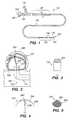
- FIG. 2is a side-elevational view of a distal portion of the catheter illustrated in FIG. 1 in a blood vessel with an embodiment of the magnetic embolization apparatus shown disposed in an aneurysm.
- FIGS. 3-5illustrate alternative embodiments of the magnetic embolization apparatus.
- FIG. 6is a view similar to FIG. 2, but with a magnetically directable embolic delivery catheter shown next to the magnetic embolization apparatus catheter.
- FIG. 7is view similar to FIG. 2, but with an embodiment of a dual lumen catheter shown.
- FIG. 8is side-elevational view of a distal portion of a catheter with a further embodiment of a magnetic embolization apparatus shown.
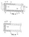
- FIG. 9is a cross-sectional view of a distal portion of a catheter including a further embodiment of a magnetic embolization apparatus disposed therein.
- FIG. 10is a cross-sectional view of a distal portion of a catheter including a still further embodiment of a magnetic embolization apparatus disposed therein.
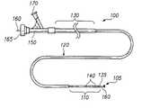
- an exemplary multi-section catheter 100that may be used to deliver and deploy a magnetic embolization apparatus 105 , which is constructed in accordance with an embodiment of the invention, at a targeted aneurysm 107 (FIG. 2) will now be described.
- a targeted aneurysm 107FIG. 2
- the inventionwill be described in terms of aneurysm treatment, it may also be adaptable for endovascular occlusion in arteries, veins, vascular malformations, and arteriovenous fistulas.
- the inventionmay also be used for forming an occlusion in other areas of a mammalian body.
- the catheter 100includes a distal section 110 , an intermediate section 120 , and a proximal section 130 .
- the sectionsdecrease in flexibility from the proximal section 130 to the distal section 110 .
- the distal section 110is very flexible and soft to allow deep penetration into the extraordinary convolutions of the neurological vasculature without trauma.
- the magnetic embolization apparatus 105is deployed from the distal section 110 of the catheter 100 at a distal end 135 .
- the distal section 110may include one or more radio-opaque bands 140 to allow viewing of the position of the distal section under fluoroscopy.
- a luer assembly 150 at the proximal section 130 of the catheter 100accomodates a pusher, core, or guide wire 160 .
- the wire 160may be made of any well-known guide wire material in the art such as stainless steel.
- the magnetic embolization apparatus 105may be attached to a distal end of the wire 160 .
- the luer assembly 150may also include a fluid port 165 for introducing and/or removing a magnetically controllable embolization substance and a power port 170 for connecting the catheter 100 to a power supply.
- the catheter 100may also include any well-known steering assembly in the art for delivering the magnetic embolization apparatus 105 to the targeted aneurysm 107 .
- the apparatus 105includes one or more magnetic segments 200 attached to an element shaped to retain or secure the apparatus 105 within the aneurysm 107 .
- the permanent magnetic segments 200(and the permanent magnets described below) may be made out of a material that safely dissolves over time or loses its magnetization over time so that MRJ may be used post surgery.
- the elementis a Guglielmi Detachable Coil (GDC®) assembly 205 made of platinum and sold by Target Therapeutics, Inc. of Fremont, Calif.
- GDC®Guglielmi Detachable Coil
- the coil assembly 205When the coil assembly 205 is deployed into the aneurysm 107 , the coil assembly 205 preferably has a convoluted configuration. This three-dimensional, convoluted configuration helps to secure the apparatus 105 in the aneurysm 107 .
- the coil assembly 205is detachably coupled to the wire 160 by a detachment mechanism 250 .
- detachment mechanismsinclude a mechanical detachment mechanism such as that described in U.S. Pat. No. 5,250,071 (“the '71 patent”) to Palermo and an electrolytic detachment mechanism such as those described in U.S. Pat. No. 5,122,136 (“the '136 patent”) to Guglielmi, et al. and U.S. Pat. No. 6,123,714 (“the '714 patent) to Gia, et al.
- the '71, '136, and '714 patentsare incorporated by reference as though set forth in full.
- an electrolytic detachment mechanismsimilar to those described in the '136 patent or the '714 patent is used.
- An electrolytic detachment mechanismincludes an electrolytic, sacrificial joint that separates when a small electric current is applied therethrough.
- the '136 patentdescribes a soldered electrolytic, sacrificial joint and the '714 patent describes a solderless electrolytic, sacrificial joint.
- the wire 160is preferably fine enough to allow an embolic to be delivered through the same lumen that the wire 160 is disposed within.
- the magnetic embolization apparatus 105may include other configurations.
- the magnetic embolization apparatus 105may have a generally bullet-shaped configuration with a partially spherical magnetic section 252 .
- the apparatus 105 illustrated in FIG. 3may have a completely spherical configuration and magnetic section.
- the apparatus 105may have an umbrella-like configuration with magnetic segments 254 located on struts 256 of the apparatus 105 .
- a reciprocating base 258may be coupled to a control device (not shown) for controlling arms 260 of the apparatus 105 .
- strutsmay carry a magnetic, generally hemispherical dome member.
- the apparatus 105may include a diamond-shape fibered platinum coil assembly 262 sold by Target Therapeutics, Inc. of Fremont, Calif. All of the embodiments of the apparatus 105 described above have advantageous configurations because, once deployed in the aneurysm 107 , they concentrate the magnetic field near a central part of the dome 390 of the aneurysm 107 . This helps to draw the magnetically controllable embolic deeper into the aneurysm 107 , away from a neck 385 of the aneurysm 107 .
- the apparatus 105may come in a variety of sizes to accommodate different size aneurysms 107 and/or a variety of configurations to accommodate aneurysms 107 having different shapes.
- the catheter 100is introduced into the vasculature of a patient via a cannula or introducer sheath and snaked through the vasculature of the patient to the targeted aneurysm 107 by any well-known method in the art. X-ray, fluoroscopy or other well-know visualization techniques may be used to assist the physician in directing the catheter 100 to the targeted aneurysm 107 .
- the catheter 100may be introduced over a guide wire such as the guide wire 106 to facilitate delivery of the catheter 100 to the targeted aneurysm 107 .
- the apparatus 105may be located in the catheter 100 , for example, in the distal portion 110 of the catheter 100 .
- the apparatus 105may be introduced through the catheter 100 with the help of the wire 160 after the catheter 100 is directed to the targeted aneurysm site.
- the distal end 135 of the catheter 100may be positioned at the aneurysm site adjacent the neck 385 of the aneurysm 107 , at the neck 385 of the aneurysm 107 , or within the aneurysm 107 .
- the apparatus 105may be deployed within the aneurysm 107 . This may be accomplished by advancing the pusher wire 160 distally through the catheter 100 .
- the apparatus 105has a pre-shaped memory so that the apparatus 105 will automatically deploy into the convoluted, three-dimensional configuration shown in FIG. 2 when the apparatus 105 is advanced into the aneurysm 107 .
- the catheter 100may include a sheath that is retracted to deploy the apparatus 105 . In the embodiments of the apparatus 105 illustrated in FIGS.
- the apparatus 105is positioned in the aneurysm 107 so that the magnet portion 252 , 254 , 260 is positioned near a top center of the dome 390 of the aneurysm 107 .
- the configuration of the apparatus 105helps to secure the apparatus 105 within the aneurysm 107 .
- the distal end 135 of the catheter 100is centered within the dome 390 of the aneurysm 107 , and a magnetically controllable embolic such as an acrylic, iron-containing glue that hardens over time is delivered to the aneurysm 107 via the same lumen of the catheter 100 as that through which the apparatus 105 and the wire 160 are introduced.
- the embolicmay have a different composition.
- the embolicmay be made of a composition that loses its magnetic controllability so that MRI may be used post surgery.
- the one or more permanent magnets 200 of the apparatus 105internally attracts, from within the aneurysm 107 , the iron-containing embolic to the one or more magnets 200 at the dome 390 of the aneurysm 107 , filling the aneurysm 107 .
- the apparatus 105may be detached from the wire 160 using the detachment mechanism 250 before or after the embolic is delivered to the aneurysm 107 . Further, if the apparatus 105 is detached from the wire 160 after the embolic is delivered to the aneurysm 107 , the apparatus 105 may be detached from the wire 160 after the embolic has sufficiently hardened or polymerized in the aneurysm 107 .
- the apparatus 105is left in the aneurysm 107 and the catheter 100 is withdrawn from the patient's body.
- the apparatus 105may not be detached from the wire 160 (no detachment mechanism 250 ) after the apparatus 105 is deployed in the aneurysm 107 .
- the magnetically controllable embolicmay be introduced into the aneurysm 107 after the apparatus 105 is deployed in the aneurysm 107 , and after a period of time that is sufficient to magnetically induce the embolic to fill the aneurysm 107 and allow the embolic to partially polymerize, the apparatus is retracted into the distal portion 110 of the catheter 100 and the catheter 100 is withdrawn with the apparatus 105 therein.
- the catheter 100may be used to deliver and deploy the apparatus 106 to the targeted aneurysm site in the manner described above, and, instead of deliverying the magnetically controllable embolic through the same catheter, a separate embolic delivery catheter 265 may be used to deliver the embolic to the aneurysm 107 .
- the catheter 100may be a dual-lumen catheter defined by respective lumen walls.
- the apparatus 105may be delivered to the targeted aneurysm 107 using the wire 160 via a first lumen 267 , and the magnetically controllable embolic may be delivered to aneurysm 107 via a second lumen 269 .
- the detachable embolization apparatus 105may include an electromagnet that is used to internally induce a magnetic field within the aneurysm 107 for embolizing the aneurysm 107 by running electrical current through the electromagnet.
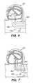
- an embodiment of an electromagnetic detachable embolization apparatus 500is shown.
- the apparatus 500includes a curvilinear, toroid-shaped electromagnet 503 and a pair of wire loops 520 to help secure the apparatus 500 within the aneurysm 107 .
- the electromagnetmay have different configurations besides a toroidal, curvilinear configuration.
- the electromagnet 503 and the wire loops 520are coupled to a guide wire 522 .
- the guide wire 522may include an insulated lead wire 505 and return wire 515 coupled to a power source 517 near the proximal section 130 of the catheter 100 .
- the guide wire 522may include a detachment mechanism, as described above.
- the electromagnet 503includes a main wire 525 , an insulated structural support wire 535 , a first insulating separator 545 , and a second insulating separator 555 .
- the main wire 525has a lead end 565 electrically connected to the lead wire 505 and a return end 575 electrically connected to the return wire 515 .
- the first insulating separator 545connects the lead wire 505 to a first portion 585 of the insulated structural support wire 535 and the second insulating separator 555 connects the return wire 515 to a second portion 595 of the insulated structural support wire 535 .
- the main wire 525includes numerous coils 600 that together form the curvilinear, toroid shape of the electromagnet 503 .
- the catheter 100is snaked through the vasculature of the patient to a targeted aneurysm 107 with the electromagnetic embolization apparatus 500 collapsed within the distal portion 100 of the catheter 100 .
- the apparatus 500is deployed within the aneurysm 107 so that the electromagnet 503 is positioned near a top center of the dome 390 of the aneurysm 107 .
- the wire loops 520hold the apparatus 500 securely within the aneurysm 107 .
- Current supplied by the power source 517 through the insulated lead wire 505flows through the electromagnet 503 , electromagnetically and internally inducing a magnetic field in the aneurysm 107 .
- the currentreturns throughout the return wire 515 .
- the currentmay be returned through a return wire in the catheter body; however, returning the current through the wire 160 is more efficient.
- the magnetically controllable embolicis delivered to the aneurysm 107 .
- Thismay be done via the same catheter 100 as illustrated in FIG. 2, a separate embolic deliver catheter 265 as illustrated in FIG. 6, or a dual lumen catheter 100 as illustrated in FIG. 7 .
- the electromagnet 503 of the apparatus 500attracts the iron-containing embolic to the electromagnet 503 , filling the aneurysm 107 .
- the apparatus 500may be detached, if a detachment mechanism exists, and left impregnated in the hardened embolic, within the aneurysm 107 .
- the apparatus 500may not be detached from the guide wire 522 (no detachment mechanism) after the apparatus 500 is deployed in the aneurysm 107 .
- the magnetically controllable embolicmay be introduced into the aneurysm 107 after the apparatus 500 is deployed in the aneurysm 107 , and after a period of time that is sufficient to magnetically induce the embolic to fill the aneurysm 107 and allow the embolic to polymerize, the apparatus 500 is retracted into the distal portion 110 of the catheter 100 and the catheter 100 is withdrawn with the apparatus 500 therein.
- the apparatus 700includes a coiled electromagnet 710 located in the catheter body in the distal portion 110 of the catheter 100 . Electrical current is supplied to the electromagnet 710 by a power source 720 via a lead wire 730 and is returned by a return wire 740 .
- a radio-opaque marker 750may be located in the catheter body at the distal end 135 of the catheter 100 to assist in locating the distal portion 110 of the catheter 100 in the vasculature of the patient using fluoroscopy.
- a plug 760may be located in the distal end 135 of the catheter 100 to prevent the magnetically directable embolic from being magnetically drawn into the distal portion 110 of the catheter 100 when the electromagnet 710 is actuated.
- the catheter 100is snaked through the vasculature of the patient to the targeted aneurysm 107 .
- the distal end 135 of the catheter 100is positioned into the aneurysm 107 , near the dome 390 .
- the radio-opaque marker 135may be used with conventional fluoroscopy equipment to assist in positioning the distal end 135 of the catheter 100 .
- the distal end of a separate embolic deliver catheter 265as illustrated in FIG. 6, may be positioned in the aneurysm 107 , adjacent the catheter 100 , for delivering a magnetically controllable embolic to the aneurysm 107 .
- FIG. 6Alternatively, as illustrated in FIG.
- the catheter 107may be a dual lumen catheter with one lumen/lumen wall having a configuration similar to the catheter 100 illustrated in FIG. 9 and an adjacent lumen/lumen wall configured to deliver the embolic to the aneurysm 107 .
- Currentis supplied by the power source 720 through the lead wire 730 to actuate the electromagnet 710 , electromagnetically and internally inducing a magnetic field 760 in the aneurysm 107 .
- the currentreturns throught the return wire 740 .
- the magnetically controllable embolicis delivered to the aneurysm 107 .
- the electromagnet 710 of the apparatus 500attracts the iron-containing embolic along the magnetic field lines 760 induced by the electromagnet 503 , filling the aneurysm 107 .
- the magnetic field 760may be terminated by cutting off power to the electromagnet 710 , and the catheter 100 may be withdrawn.
- Advantages of this embodimentinclude a guide wire is not required to deliver the magnetic embolization apparatus, the apparatus 700 is not left in the aneurysm 107 after embolization, and the apparatus 700 does not have to be withdrawn through a partially or fully polymerized embolic in the aneurysm 107 .
- the apparatus 800includes a coiled permanent magnet 810 located in the catheter body in the distal portion 110 of the catheter 100 .
- a coiled magnet configuration or similar configurationis advantageous for providing the distal portion 110 of the catheter 100 with the requisite flexibility and to minimize catheter tip stiffness.
- a radio-opaque marker 850may be located in the catheter body at the distal end 135 of the catheter 100 to assist in locating the distal portion 110 of the catheter 100 in the vasculature of the patient using fluoroscopy.
- a plug 860may be located in the distal end 135 of the catheter 100 to prevent the magnetically directable embolic from being magnetically drawn into the distal portion 110 of the catheter 100 .
- the method of use for the permanent magnetic embolization apparatus 800is the same as that for the electromagnetic embolization apparatus 700 , except that current is not supplied to the permanent magnet 810 to induce a magnetic field because a magnetic field always exists at the distal portion 100 .
- the electromagnet 710 of FIG. 9may be combined with the permanent magnet 810 of FIG. 10 in the distal portion 110 of the catheter 100 to induce a stronger magnetic field in the aneurysm 107 .
- the above-described embodiments of the inventioninternally induce a magnetic field, from within the aneurysm, to embolize the aneurysm with a magnetically-directable embolic.
Landscapes
- Health & Medical Sciences (AREA)
- Surgery (AREA)
- Life Sciences & Earth Sciences (AREA)
- Heart & Thoracic Surgery (AREA)
- Molecular Biology (AREA)
- Vascular Medicine (AREA)
- Engineering & Computer Science (AREA)
- Biomedical Technology (AREA)
- Reproductive Health (AREA)
- Medical Informatics (AREA)
- Nuclear Medicine, Radiotherapy & Molecular Imaging (AREA)
- Animal Behavior & Ethology (AREA)
- General Health & Medical Sciences (AREA)
- Public Health (AREA)
- Veterinary Medicine (AREA)
- Neurosurgery (AREA)
- Surgical Instruments (AREA)
Abstract
Description
Claims (50)
Priority Applications (6)
| Application Number | Priority Date | Filing Date | Title |
|---|---|---|---|
| US09/752,747US6603994B2 (en) | 2000-12-28 | 2000-12-28 | Apparatus and method for internally inducing a magnetic field in an aneurysm to embolize aneurysm with magnetically-controllable substance |
| EP01988436AEP1345537A2 (en) | 2000-12-28 | 2001-12-26 | Apparatus and method for embolizing an aneurysm with magnetically-controllable substance |
| PCT/US2001/050849WO2002053042A2 (en) | 2000-12-28 | 2001-12-26 | Apparatus and method for embolizing an aneurysm with magnetically-controllable substance |
| JP2002553995AJP2004516882A (en) | 2000-12-28 | 2001-12-26 | Apparatus and method for inducing a magnetic field within an aneurysm to embolize the aneurysm with a magnetically controllable substance |
| AU2002241743AAU2002241743A1 (en) | 2000-12-28 | 2001-12-26 | Apparatus and method for embolizing an aneurysm with magnetically-controllable substance |
| CA002433012ACA2433012A1 (en) | 2000-12-28 | 2001-12-26 | Apparatus and method for embolizing an aneurysm with magnetically-controllable substance |
Applications Claiming Priority (1)
| Application Number | Priority Date | Filing Date | Title |
|---|---|---|---|
| US09/752,747US6603994B2 (en) | 2000-12-28 | 2000-12-28 | Apparatus and method for internally inducing a magnetic field in an aneurysm to embolize aneurysm with magnetically-controllable substance |
Publications (2)
| Publication Number | Publication Date |
|---|---|
| US20020087077A1 US20020087077A1 (en) | 2002-07-04 |
| US6603994B2true US6603994B2 (en) | 2003-08-05 |
Family
ID=25027654
Family Applications (1)
| Application Number | Title | Priority Date | Filing Date |
|---|---|---|---|
| US09/752,747Expired - Fee RelatedUS6603994B2 (en) | 2000-12-28 | 2000-12-28 | Apparatus and method for internally inducing a magnetic field in an aneurysm to embolize aneurysm with magnetically-controllable substance |
Country Status (6)
| Country | Link |
|---|---|
| US (1) | US6603994B2 (en) |
| EP (1) | EP1345537A2 (en) |
| JP (1) | JP2004516882A (en) |
| AU (1) | AU2002241743A1 (en) |
| CA (1) | CA2433012A1 (en) |
| WO (1) | WO2002053042A2 (en) |
Cited By (67)
| Publication number | Priority date | Publication date | Assignee | Title |
|---|---|---|---|---|
| WO2006039675A3 (en)* | 2004-10-01 | 2006-06-29 | Childrens Medical Center | Apparatus and method for nanomanipulation of biomolecules and living cells |
| WO2006042117A3 (en)* | 2004-10-06 | 2006-10-26 | Sherwood Serv Ag | Systems and methods for thermally profiling radiofrequency electrodes |
| US20070072466A1 (en)* | 2005-09-27 | 2007-03-29 | Manabu Miyamoto | Instrument for endoscope |
| US20080015664A1 (en)* | 2004-10-06 | 2008-01-17 | Podhajsky Ronald J | Systems and methods for thermally profiling radiofrequency electrodes |
| US20080027482A1 (en)* | 2006-07-28 | 2008-01-31 | Terumo Kabushiki Kaisha | Elongate medical device |
| US20080123716A1 (en)* | 2006-09-13 | 2008-05-29 | Sherwood Services Ag | Portable thermally profiling phantom and method of using the same |
| US20090118613A1 (en)* | 2007-11-01 | 2009-05-07 | Tyco Healthcare Group Lp | Method for Volume Determination and Geometric Reconstruction |
| US20090131926A1 (en)* | 2007-11-16 | 2009-05-21 | Tyco Healthcare Group Lp | Dynamically Matched Microwave Antenna for Tissue Ablation |
| US20090138004A1 (en)* | 2007-11-27 | 2009-05-28 | Vivant Medical, Inc. | System and Method for Field Ablation Prediction |
| US20090187180A1 (en)* | 2008-01-23 | 2009-07-23 | Vivant Medical, Inc. | Choked Dielectric Loaded Tip Dipole Microwave Antenna |
| US20090192510A1 (en)* | 2008-01-29 | 2009-07-30 | Tyco Healthcare Group Lp | Polyp Encapsulation System and Method |
| US20090198227A1 (en)* | 2008-01-31 | 2009-08-06 | Vivant Medical, Inc. | Articulating Ablation Device and Method |
| US20090198226A1 (en)* | 2008-01-31 | 2009-08-06 | Vivant Medical, Inc. | Medical Device Including Member that Deploys in a Spiral-Like Configuration and Method |
| US20090248005A1 (en)* | 2008-03-27 | 2009-10-01 | Rusin Christopher T | Microwave Ablation Devices Including Expandable Antennas and Methods of Use |
| US20090248006A1 (en)* | 2008-03-31 | 2009-10-01 | Paulus Joseph A | Re-Hydration Antenna for Ablation |
| US20090306652A1 (en)* | 2008-06-09 | 2009-12-10 | Buysse Steven P | Ablation Needle Guide |
| US20090306659A1 (en)* | 2008-06-09 | 2009-12-10 | Buysse Steven P | Surface Ablation Process With Electrode Cooling Methods |
| US20100030208A1 (en)* | 2008-07-29 | 2010-02-04 | Tyco Healthcare Group Lp | Method for Ablation Volume Determination and Geometric Reconstruction |
| US20100045559A1 (en)* | 2008-08-25 | 2010-02-25 | Vivant Medical, Inc. | Dual-Band Dipole Microwave Ablation Antenna |
| US20100045558A1 (en)* | 2008-08-25 | 2010-02-25 | Vivant Medical, Inc. | Dual-Band Dipole Microwave Ablation Antenna |
| US20100053015A1 (en)* | 2008-08-28 | 2010-03-04 | Vivant Medical, Inc. | Microwave Antenna |
| US20100057070A1 (en)* | 2008-09-03 | 2010-03-04 | Vivant Medical, Inc. | Microwave Shielding Apparatus |
| US20100087808A1 (en)* | 2008-10-03 | 2010-04-08 | Vivant Medical, Inc. | Combined Frequency Microwave Ablation System, Devices and Methods of Use |
| US20100097284A1 (en)* | 2008-10-17 | 2010-04-22 | Vivant Medical, Inc. | Choked Dielectric Loaded Tip Dipole Microwave Antenna |
| US20100217251A1 (en)* | 2009-02-20 | 2010-08-26 | Vivant Medical, Inc. | Leaky-Wave Antennas for Medical Applications |
| US20100256624A1 (en)* | 2009-04-01 | 2010-10-07 | Vivant Medical, Inc. | Microwave Ablation System with User-Controlled Ablation Size and Method of Use |
| US20100286682A1 (en)* | 2009-05-06 | 2010-11-11 | Vivant Medical, Inc. | Power-Stage Antenna Integrated System with Junction Member |
| US20100286683A1 (en)* | 2009-05-06 | 2010-11-11 | Vivant Medical, Inc. | Power-Stage Antenna Integrated System with High-Strength Shaft |
| US20100286681A1 (en)* | 2009-05-06 | 2010-11-11 | Vivant Medical, Inc. | Power-Stage Antenna Integrated System |
| US20100305560A1 (en)* | 2009-05-29 | 2010-12-02 | Vivant Medical, Inc. | Microwave Ablation Safety Pad, Microwave Safety Pad System and Method of Use |
| US20100331834A1 (en)* | 2009-06-29 | 2010-12-30 | Vivant Medical,Inc. | Ablation Probe Fixation |
| US20110034913A1 (en)* | 2009-08-05 | 2011-02-10 | Vivant Medical, Inc. | Directive Window Ablation Antenna with Dielectric Loading |
| US20110034919A1 (en)* | 2009-08-06 | 2011-02-10 | Vivant Medical, Inc. | Vented Positioner and Spacer and Method of Use |
| US20110040300A1 (en)* | 2009-08-17 | 2011-02-17 | Vivant Medical, Inc. | Surface Ablation Antenna with Dielectric Loading |
| USD634010S1 (en) | 2009-08-05 | 2011-03-08 | Vivant Medical, Inc. | Medical device indicator guide |
| US20110060325A1 (en)* | 2009-09-08 | 2011-03-10 | Vivant Medical, Inc. | Microwave Antenna Probe with High-Strength Ceramic Coupler |
| US20110066144A1 (en)* | 2009-09-16 | 2011-03-17 | Vivant Medical, Inc. | Perfused Core Dielectrically Loaded Dipole Microwave Antenna Probe |
| US20110218527A1 (en)* | 2010-03-08 | 2011-09-08 | Vivant Medical, Inc. | Microwave Antenna Probe Having a Deployable Ground Plane |
| US8202270B2 (en) | 2009-02-20 | 2012-06-19 | Vivant Medical, Inc. | Leaky-wave antennas for medical applications |
| US8246614B2 (en) | 2008-04-17 | 2012-08-21 | Vivant Medical, Inc. | High-strength microwave antenna coupling |
| US8292881B2 (en) | 2009-05-27 | 2012-10-23 | Vivant Medical, Inc. | Narrow gauge high strength choked wet tip microwave ablation antenna |
| US8292880B2 (en) | 2007-11-27 | 2012-10-23 | Vivant Medical, Inc. | Targeted cooling of deployable microwave antenna |
| US8328860B2 (en) | 2007-03-13 | 2012-12-11 | Covidien Lp | Implant including a coil and a stretch-resistant member |
| USD673685S1 (en) | 2010-09-08 | 2013-01-01 | Vivant Medical, Inc. | Microwave device spacer and positioner with arcuate slot |
| US8552915B2 (en) | 2009-06-19 | 2013-10-08 | Covidien Lp | Microwave ablation antenna radiation detector |
| US8777978B2 (en) | 2006-04-17 | 2014-07-15 | Covidien Lp | System and method for mechanically positioning intravascular implants |
| US8777979B2 (en) | 2006-04-17 | 2014-07-15 | Covidien Lp | System and method for mechanically positioning intravascular implants |
| US8801747B2 (en) | 2007-03-13 | 2014-08-12 | Covidien Lp | Implant, a mandrel, and a method of forming an implant |
| US8894641B2 (en) | 2009-10-27 | 2014-11-25 | Covidien Lp | System and method for monitoring ablation size |
| US8945144B2 (en) | 2010-09-08 | 2015-02-03 | Covidien Lp | Microwave spacers and method of use |
| US8968289B2 (en) | 2010-10-22 | 2015-03-03 | Covidien Lp | Microwave spacers and methods of use |
| US9011480B2 (en) | 2012-01-20 | 2015-04-21 | Covidien Lp | Aneurysm treatment coils |
| US9050095B2 (en) | 2004-09-22 | 2015-06-09 | Covidien Lp | Medical implant |
| US9057468B2 (en) | 2007-11-27 | 2015-06-16 | Covidien Lp | Wedge coupling |
| US9113624B2 (en) | 2008-10-15 | 2015-08-25 | Covidien Lp | System and method for perfusing biological organs |
| US9198665B2 (en) | 2004-09-22 | 2015-12-01 | Covidien Lp | Micro-spiral implantation device |
| US9254172B2 (en) | 2008-09-03 | 2016-02-09 | Covidien Lp | Shielding for an isolation apparatus used in a microwave generator |
| US9358140B1 (en) | 2009-11-18 | 2016-06-07 | Aneuclose Llc | Stent with outer member to embolize an aneurysm |
| US9579104B2 (en) | 2011-11-30 | 2017-02-28 | Covidien Lp | Positioning and detaching implants |
| US9681916B2 (en) | 2012-01-06 | 2017-06-20 | Covidien Lp | System and method for treating tissue using an expandable antenna |
| US9687245B2 (en) | 2012-03-23 | 2017-06-27 | Covidien Lp | Occlusive devices and methods of use |
| US9693823B2 (en) | 2012-01-06 | 2017-07-04 | Covidien Lp | System and method for treating tissue using an expandable antenna |
| US9713475B2 (en) | 2014-04-18 | 2017-07-25 | Covidien Lp | Embolic medical devices |
| US10028747B2 (en) | 2008-05-01 | 2018-07-24 | Aneuclose Llc | Coils with a series of proximally-and-distally-connected loops for occluding a cerebral aneurysm |
| US10045819B2 (en) | 2009-04-14 | 2018-08-14 | Covidien Lp | Frequency identification for microwave ablation probes |
| US10716573B2 (en) | 2008-05-01 | 2020-07-21 | Aneuclose | Janjua aneurysm net with a resilient neck-bridging portion for occluding a cerebral aneurysm |
| US10953204B2 (en) | 2017-01-09 | 2021-03-23 | Boston Scientific Scimed, Inc. | Guidewire with tactile feel |
Families Citing this family (5)
| Publication number | Priority date | Publication date | Assignee | Title |
|---|---|---|---|---|
| JP6418613B2 (en)* | 2016-05-31 | 2018-11-07 | 国立大学法人信州大学 | Embolic coil |
| JP2021520255A (en)* | 2018-04-04 | 2021-08-19 | インキュメデックス インコーポレイテッド | Embolic device with improved reduced diameter coating |
| US20220054139A1 (en)* | 2020-08-18 | 2022-02-24 | Merit Medical Systems, Inc. | Embolic basket, particles, and related methods |
| US20250090175A1 (en)* | 2021-08-03 | 2025-03-20 | Medstar Health, Inc. | Embolization device |
| EP4201344A1 (en)* | 2021-12-24 | 2023-06-28 | Artedrone | Device and system for treatment of a vessel |
Citations (11)
| Publication number | Priority date | Publication date | Assignee | Title |
|---|---|---|---|---|
| US5122136A (en) | 1990-03-13 | 1992-06-16 | The Regents Of The University Of California | Endovascular electrolytically detachable guidewire tip for the electroformation of thrombus in arteries, veins, aneurysms, vascular malformations and arteriovenous fistulas |
| US5250071A (en) | 1992-09-22 | 1993-10-05 | Target Therapeutics, Inc. | Detachable embolic coil assembly using interlocking clasps and method of use |
| US5984929A (en) | 1997-08-29 | 1999-11-16 | Target Therapeutics, Inc. | Fast detaching electronically isolated implant |
| US6014580A (en) | 1997-11-12 | 2000-01-11 | Stereotaxis, Inc. | Device and method for specifying magnetic field for surgical applications |
| WO2000007641A2 (en) | 1998-08-07 | 2000-02-17 | Stereotaxis, Inc. | Method and apparatus for magnetically controlling catheters in body lumens and cavities |
| US6032677A (en)* | 1998-07-17 | 2000-03-07 | Blechman; Abraham M. | Method and apparatus for stimulating the healing of medical implants |
| WO2000054835A1 (en) | 1999-03-17 | 2000-09-21 | Stereotaxis, Inc. | Methods of and apparatus for treating vascular defects |
| WO2000054832A1 (en) | 1999-03-17 | 2000-09-21 | Stereotaxis, Inc. | Methods of and compositions for treating vascular defects |
| US6123714A (en) | 1994-12-30 | 2000-09-26 | Target Therapeutics, Inc. | System for detaching an occlusive device within a body using a solderless, electrolytically severable joint |
| US6190373B1 (en)* | 1992-11-13 | 2001-02-20 | Scimed Life Systems, Inc. | Axially detachable embolic coil assembly |
| WO2001015608A1 (en) | 1999-08-31 | 2001-03-08 | Micro Therapeutics, Inc. | Controlled injection of liquid embolic composition |
- 2000
- 2000-12-28USUS09/752,747patent/US6603994B2/ennot_activeExpired - Fee Related
- 2001
- 2001-12-26EPEP01988436Apatent/EP1345537A2/ennot_activeWithdrawn
- 2001-12-26WOPCT/US2001/050849patent/WO2002053042A2/ennot_activeApplication Discontinuation
- 2001-12-26AUAU2002241743Apatent/AU2002241743A1/ennot_activeAbandoned
- 2001-12-26JPJP2002553995Apatent/JP2004516882A/enactivePending
- 2001-12-26CACA002433012Apatent/CA2433012A1/ennot_activeAbandoned
Patent Citations (14)
| Publication number | Priority date | Publication date | Assignee | Title |
|---|---|---|---|---|
| US5895385A (en)* | 1990-03-13 | 1999-04-20 | The Regents Of The University Of California | Endovascular electrolytically detachable wire and tip for the formation of thrombus in arteries, veins, aneurysms, vascular malformations and arteriovenous fistulas |
| US5122136A (en) | 1990-03-13 | 1992-06-16 | The Regents Of The University Of California | Endovascular electrolytically detachable guidewire tip for the electroformation of thrombus in arteries, veins, aneurysms, vascular malformations and arteriovenous fistulas |
| US5250071A (en) | 1992-09-22 | 1993-10-05 | Target Therapeutics, Inc. | Detachable embolic coil assembly using interlocking clasps and method of use |
| US6190373B1 (en)* | 1992-11-13 | 2001-02-20 | Scimed Life Systems, Inc. | Axially detachable embolic coil assembly |
| US6123714A (en) | 1994-12-30 | 2000-09-26 | Target Therapeutics, Inc. | System for detaching an occlusive device within a body using a solderless, electrolytically severable joint |
| US5984929A (en) | 1997-08-29 | 1999-11-16 | Target Therapeutics, Inc. | Fast detaching electronically isolated implant |
| US6014580A (en) | 1997-11-12 | 2000-01-11 | Stereotaxis, Inc. | Device and method for specifying magnetic field for surgical applications |
| US6032677A (en)* | 1998-07-17 | 2000-03-07 | Blechman; Abraham M. | Method and apparatus for stimulating the healing of medical implants |
| WO2000007641A2 (en) | 1998-08-07 | 2000-02-17 | Stereotaxis, Inc. | Method and apparatus for magnetically controlling catheters in body lumens and cavities |
| WO2000054835A1 (en) | 1999-03-17 | 2000-09-21 | Stereotaxis, Inc. | Methods of and apparatus for treating vascular defects |
| WO2000054832A1 (en) | 1999-03-17 | 2000-09-21 | Stereotaxis, Inc. | Methods of and compositions for treating vascular defects |
| US6364823B1 (en)* | 1999-03-17 | 2002-04-02 | Stereotaxis, Inc. | Methods of and compositions for treating vascular defects |
| US6375606B1 (en)* | 1999-03-17 | 2002-04-23 | Stereotaxis, Inc. | Methods of and apparatus for treating vascular defects |
| WO2001015608A1 (en) | 1999-08-31 | 2001-03-08 | Micro Therapeutics, Inc. | Controlled injection of liquid embolic composition |
Cited By (145)
| Publication number | Priority date | Publication date | Assignee | Title |
|---|---|---|---|---|
| US9050095B2 (en) | 2004-09-22 | 2015-06-09 | Covidien Lp | Medical implant |
| US9198665B2 (en) | 2004-09-22 | 2015-12-01 | Covidien Lp | Micro-spiral implantation device |
| WO2006039675A3 (en)* | 2004-10-01 | 2006-06-29 | Childrens Medical Center | Apparatus and method for nanomanipulation of biomolecules and living cells |
| WO2006042117A3 (en)* | 2004-10-06 | 2006-10-26 | Sherwood Serv Ag | Systems and methods for thermally profiling radiofrequency electrodes |
| US20080015664A1 (en)* | 2004-10-06 | 2008-01-17 | Podhajsky Ronald J | Systems and methods for thermally profiling radiofrequency electrodes |
| US20090054887A1 (en)* | 2004-10-06 | 2009-02-26 | Covidien Ag | Systems and Methods for Thermally Profiling Radiofrequency Electrodes |
| US7947035B2 (en) | 2005-09-27 | 2011-05-24 | Olympus Medical Systems Corp. | Instrument for endoscope having pivotable offset portions |
| US20070072466A1 (en)* | 2005-09-27 | 2007-03-29 | Manabu Miyamoto | Instrument for endoscope |
| US20070260114A1 (en)* | 2005-09-27 | 2007-11-08 | Manabu Miyamoto | Instrument for endoscope |
| US8864790B2 (en) | 2006-04-17 | 2014-10-21 | Covidien Lp | System and method for mechanically positioning intravascular implants |
| US8795321B2 (en) | 2006-04-17 | 2014-08-05 | Covidien Lp | System and method for mechanically positioning intravascular implants |
| US8795320B2 (en) | 2006-04-17 | 2014-08-05 | Covidien Lp | System and method for mechanically positioning intravascular implants |
| US8777979B2 (en) | 2006-04-17 | 2014-07-15 | Covidien Lp | System and method for mechanically positioning intravascular implants |
| US8777978B2 (en) | 2006-04-17 | 2014-07-15 | Covidien Lp | System and method for mechanically positioning intravascular implants |
| US8414634B2 (en)* | 2006-07-28 | 2013-04-09 | Terumo Kabushiki Kaisha | Elongate medical device |
| US20080027482A1 (en)* | 2006-07-28 | 2008-01-31 | Terumo Kabushiki Kaisha | Elongate medical device |
| US20080123716A1 (en)* | 2006-09-13 | 2008-05-29 | Sherwood Services Ag | Portable thermally profiling phantom and method of using the same |
| US8002462B2 (en)* | 2006-09-13 | 2011-08-23 | Covidien Ag | Portable thermally profiling phantom and method of using the same |
| US9289215B2 (en) | 2007-03-13 | 2016-03-22 | Covidien Lp | Implant including a coil and a stretch-resistant member |
| US8801747B2 (en) | 2007-03-13 | 2014-08-12 | Covidien Lp | Implant, a mandrel, and a method of forming an implant |
| US8328860B2 (en) | 2007-03-13 | 2012-12-11 | Covidien Lp | Implant including a coil and a stretch-resistant member |
| US20090118613A1 (en)* | 2007-11-01 | 2009-05-07 | Tyco Healthcare Group Lp | Method for Volume Determination and Geometric Reconstruction |
| US9622813B2 (en) | 2007-11-01 | 2017-04-18 | Covidien Lp | Method for volume determination and geometric reconstruction |
| US10321962B2 (en) | 2007-11-01 | 2019-06-18 | Covidien Lp | Method for volume determination and geometric reconstruction |
| US8968291B2 (en) | 2007-11-16 | 2015-03-03 | Covidien Lp | Dynamically matched microwave antenna for tissue ablation |
| US9579151B2 (en) | 2007-11-16 | 2017-02-28 | Covidien Lp | Dynamically matched microwave antenna for tissue ablation |
| US8280525B2 (en) | 2007-11-16 | 2012-10-02 | Vivant Medical, Inc. | Dynamically matched microwave antenna for tissue ablation |
| US20090131926A1 (en)* | 2007-11-16 | 2009-05-21 | Tyco Healthcare Group Lp | Dynamically Matched Microwave Antenna for Tissue Ablation |
| US8131339B2 (en) | 2007-11-27 | 2012-03-06 | Vivant Medical, Inc. | System and method for field ablation prediction |
| US8292880B2 (en) | 2007-11-27 | 2012-10-23 | Vivant Medical, Inc. | Targeted cooling of deployable microwave antenna |
| US9057468B2 (en) | 2007-11-27 | 2015-06-16 | Covidien Lp | Wedge coupling |
| US20090138004A1 (en)* | 2007-11-27 | 2009-05-28 | Vivant Medical, Inc. | System and Method for Field Ablation Prediction |
| US10058384B2 (en) | 2008-01-23 | 2018-08-28 | Covidien Lp | Choked dielectric loaded tip dipole microwave antenna |
| US9861439B2 (en) | 2008-01-23 | 2018-01-09 | Covidien Lp | Choked dielectric loaded tip dipole microwave antenna |
| US10743934B2 (en) | 2008-01-23 | 2020-08-18 | Covidien Lp | Choked dielectric loaded tip dipole microwave antenna |
| US20090187180A1 (en)* | 2008-01-23 | 2009-07-23 | Vivant Medical, Inc. | Choked Dielectric Loaded Tip Dipole Microwave Antenna |
| US12318133B2 (en) | 2008-01-23 | 2025-06-03 | Covidien Lp | Choked microwave antenna |
| US8945111B2 (en) | 2008-01-23 | 2015-02-03 | Covidien Lp | Choked dielectric loaded tip dipole microwave antenna |
| US8435237B2 (en) | 2008-01-29 | 2013-05-07 | Covidien Lp | Polyp encapsulation system and method |
| US20090192510A1 (en)* | 2008-01-29 | 2009-07-30 | Tyco Healthcare Group Lp | Polyp Encapsulation System and Method |
| US9017328B2 (en) | 2008-01-29 | 2015-04-28 | Covidien Lp | Polyp encapsulation system and method |
| US8353902B2 (en) | 2008-01-31 | 2013-01-15 | Vivant Medical, Inc. | Articulating ablation device and method |
| US20090198227A1 (en)* | 2008-01-31 | 2009-08-06 | Vivant Medical, Inc. | Articulating Ablation Device and Method |
| US8262703B2 (en) | 2008-01-31 | 2012-09-11 | Vivant Medical, Inc. | Medical device including member that deploys in a spiral-like configuration and method |
| US20090198226A1 (en)* | 2008-01-31 | 2009-08-06 | Vivant Medical, Inc. | Medical Device Including Member that Deploys in a Spiral-Like Configuration and Method |
| US9925002B2 (en) | 2008-01-31 | 2018-03-27 | Covidien Lp | Articulating ablation device and method |
| US20090248005A1 (en)* | 2008-03-27 | 2009-10-01 | Rusin Christopher T | Microwave Ablation Devices Including Expandable Antennas and Methods of Use |
| US9949794B2 (en) | 2008-03-27 | 2018-04-24 | Covidien Lp | Microwave ablation devices including expandable antennas and methods of use |
| US20090248006A1 (en)* | 2008-03-31 | 2009-10-01 | Paulus Joseph A | Re-Hydration Antenna for Ablation |
| US9198723B2 (en) | 2008-03-31 | 2015-12-01 | Covidien Lp | Re-hydration antenna for ablation |
| US9750571B2 (en) | 2008-03-31 | 2017-09-05 | Covidien Lp | Re-hydration antenna for ablation |
| US8246614B2 (en) | 2008-04-17 | 2012-08-21 | Vivant Medical, Inc. | High-strength microwave antenna coupling |
| US10028747B2 (en) | 2008-05-01 | 2018-07-24 | Aneuclose Llc | Coils with a series of proximally-and-distally-connected loops for occluding a cerebral aneurysm |
| US10716573B2 (en) | 2008-05-01 | 2020-07-21 | Aneuclose | Janjua aneurysm net with a resilient neck-bridging portion for occluding a cerebral aneurysm |
| US20090306659A1 (en)* | 2008-06-09 | 2009-12-10 | Buysse Steven P | Surface Ablation Process With Electrode Cooling Methods |
| US8192427B2 (en) | 2008-06-09 | 2012-06-05 | Tyco Healthcare Group Lp | Surface ablation process with electrode cooling methods |
| US8667674B2 (en) | 2008-06-09 | 2014-03-11 | Covidien Lp | Surface ablation process with electrode cooling methods |
| US20090306652A1 (en)* | 2008-06-09 | 2009-12-10 | Buysse Steven P | Ablation Needle Guide |
| US9763728B2 (en) | 2008-06-09 | 2017-09-19 | Covidien Lp | Ablation needle guide |
| US9271796B2 (en) | 2008-06-09 | 2016-03-01 | Covidien Lp | Ablation needle guide |
| US20100030208A1 (en)* | 2008-07-29 | 2010-02-04 | Tyco Healthcare Group Lp | Method for Ablation Volume Determination and Geometric Reconstruction |
| US8834409B2 (en) | 2008-07-29 | 2014-09-16 | Covidien Lp | Method for ablation volume determination and geometric reconstruction |
| US20100045559A1 (en)* | 2008-08-25 | 2010-02-25 | Vivant Medical, Inc. | Dual-Band Dipole Microwave Ablation Antenna |
| US20100045558A1 (en)* | 2008-08-25 | 2010-02-25 | Vivant Medical, Inc. | Dual-Band Dipole Microwave Ablation Antenna |
| US9173706B2 (en) | 2008-08-25 | 2015-11-03 | Covidien Lp | Dual-band dipole microwave ablation antenna |
| US9439730B2 (en) | 2008-08-25 | 2016-09-13 | Covidien Lp | Dual-band dipole microwave ablation antenna |
| US9198725B2 (en) | 2008-08-28 | 2015-12-01 | Covidien Lp | Microwave antenna with choke |
| US10022186B2 (en) | 2008-08-28 | 2018-07-17 | Covidien Lp | Microwave antenna with cooled handle |
| US20100053015A1 (en)* | 2008-08-28 | 2010-03-04 | Vivant Medical, Inc. | Microwave Antenna |
| US9113932B1 (en) | 2008-08-28 | 2015-08-25 | Covidien Lp | Microwave antenna with choke |
| US8251987B2 (en) | 2008-08-28 | 2012-08-28 | Vivant Medical, Inc. | Microwave antenna |
| US11147620B2 (en) | 2008-08-28 | 2021-10-19 | Covidien Lp | Microwave antenna with cooled hub |
| US9375280B2 (en) | 2008-08-28 | 2016-06-28 | Covidien Lp | Microwave antenna with cooling system |
| US9707038B2 (en) | 2008-08-28 | 2017-07-18 | Covidien Lp | Microwave antenna with cooled handle |
| US8394086B2 (en) | 2008-09-03 | 2013-03-12 | Vivant Medical, Inc. | Microwave shielding apparatus |
| US20100057070A1 (en)* | 2008-09-03 | 2010-03-04 | Vivant Medical, Inc. | Microwave Shielding Apparatus |
| US9254172B2 (en) | 2008-09-03 | 2016-02-09 | Covidien Lp | Shielding for an isolation apparatus used in a microwave generator |
| US20100087808A1 (en)* | 2008-10-03 | 2010-04-08 | Vivant Medical, Inc. | Combined Frequency Microwave Ablation System, Devices and Methods of Use |
| US9113624B2 (en) | 2008-10-15 | 2015-08-25 | Covidien Lp | System and method for perfusing biological organs |
| US10188460B2 (en) | 2008-10-17 | 2019-01-29 | Covidien Lp | Choked dielectric loaded tip dipole microwave antenna |
| US20100097284A1 (en)* | 2008-10-17 | 2010-04-22 | Vivant Medical, Inc. | Choked Dielectric Loaded Tip Dipole Microwave Antenna |
| US9113924B2 (en) | 2008-10-17 | 2015-08-25 | Covidien Lp | Choked dielectric loaded tip dipole microwave antenna |
| US10080610B2 (en) | 2009-02-20 | 2018-09-25 | Covidien Lp | Leaky-wave antennas for medical applications |
| US8679108B2 (en) | 2009-02-20 | 2014-03-25 | Covidien Lp | Leaky-wave antennas for medical applications |
| US20100217251A1 (en)* | 2009-02-20 | 2010-08-26 | Vivant Medical, Inc. | Leaky-Wave Antennas for Medical Applications |
| US8968292B2 (en) | 2009-02-20 | 2015-03-03 | Covidien Lp | Leaky-wave antennas for medical applications |
| US8608731B2 (en) | 2009-02-20 | 2013-12-17 | Covidien Lp | Leaky-wave antennas for medical applications |
| US8197473B2 (en) | 2009-02-20 | 2012-06-12 | Vivant Medical, Inc. | Leaky-wave antennas for medical applications |
| US8202270B2 (en) | 2009-02-20 | 2012-06-19 | Vivant Medical, Inc. | Leaky-wave antennas for medical applications |
| US9277969B2 (en) | 2009-04-01 | 2016-03-08 | Covidien Lp | Microwave ablation system with user-controlled ablation size and method of use |
| US10111718B2 (en) | 2009-04-01 | 2018-10-30 | Covidien Lp | Microwave ablation system with user-controlled ablation size and method of use |
| US20100256624A1 (en)* | 2009-04-01 | 2010-10-07 | Vivant Medical, Inc. | Microwave Ablation System with User-Controlled Ablation Size and Method of Use |
| US9867670B2 (en) | 2009-04-01 | 2018-01-16 | Covidien Lp | Microwave ablation system and user-controlled ablation size and method of use |
| US10499998B2 (en) | 2009-04-01 | 2019-12-10 | Covidien Lp | Microwave ablation system with user-controlled ablation size and method of use |
| US10045819B2 (en) | 2009-04-14 | 2018-08-14 | Covidien Lp | Frequency identification for microwave ablation probes |
| US10758306B2 (en) | 2009-04-14 | 2020-09-01 | Covidien Lp | Frequency identification for microwave ablation probes |
| US8216227B2 (en) | 2009-05-06 | 2012-07-10 | Vivant Medical, Inc. | Power-stage antenna integrated system with junction member |
| US8353903B2 (en) | 2009-05-06 | 2013-01-15 | Vivant Medical, Inc. | Power-stage antenna integrated system |
| US8463396B2 (en) | 2009-05-06 | 2013-06-11 | Covidien LLP | Power-stage antenna integrated system with high-strength shaft |
| US20100286681A1 (en)* | 2009-05-06 | 2010-11-11 | Vivant Medical, Inc. | Power-Stage Antenna Integrated System |
| US20100286683A1 (en)* | 2009-05-06 | 2010-11-11 | Vivant Medical, Inc. | Power-Stage Antenna Integrated System with High-Strength Shaft |
| US20100286682A1 (en)* | 2009-05-06 | 2010-11-11 | Vivant Medical, Inc. | Power-Stage Antenna Integrated System with Junction Member |
| US9833286B2 (en) | 2009-05-06 | 2017-12-05 | Covidien Lp | Power-stage antenna integrated system with high-strength shaft |
| US10499989B2 (en) | 2009-05-27 | 2019-12-10 | Covidien Lp | Narrow gauge high strength choked wet tip microwave ablation antenna |
| US9192437B2 (en) | 2009-05-27 | 2015-11-24 | Covidien Lp | Narrow gauge high strength choked wet tip microwave ablation antenna |
| US8292881B2 (en) | 2009-05-27 | 2012-10-23 | Vivant Medical, Inc. | Narrow gauge high strength choked wet tip microwave ablation antenna |
| US9662172B2 (en) | 2009-05-27 | 2017-05-30 | Covidien Lp | Narrow gauge high strength choked wet tip microwave ablation antenna |
| US20100305560A1 (en)* | 2009-05-29 | 2010-12-02 | Vivant Medical, Inc. | Microwave Ablation Safety Pad, Microwave Safety Pad System and Method of Use |
| US8834460B2 (en) | 2009-05-29 | 2014-09-16 | Covidien Lp | Microwave ablation safety pad, microwave safety pad system and method of use |
| US9625395B2 (en) | 2009-06-19 | 2017-04-18 | Covidien Lp | Microwave ablation antenna radiation detector |
| US8847830B2 (en) | 2009-06-19 | 2014-09-30 | Covidien Lp | Microwave ablation antenna radiation detector |
| US8552915B2 (en) | 2009-06-19 | 2013-10-08 | Covidien Lp | Microwave ablation antenna radiation detector |
| US20100331834A1 (en)* | 2009-06-29 | 2010-12-30 | Vivant Medical,Inc. | Ablation Probe Fixation |
| US20110034913A1 (en)* | 2009-08-05 | 2011-02-10 | Vivant Medical, Inc. | Directive Window Ablation Antenna with Dielectric Loading |
| US8328800B2 (en) | 2009-08-05 | 2012-12-11 | Vivant Medical, Inc. | Directive window ablation antenna with dielectric loading |
| USD634010S1 (en) | 2009-08-05 | 2011-03-08 | Vivant Medical, Inc. | Medical device indicator guide |
| US20110034919A1 (en)* | 2009-08-06 | 2011-02-10 | Vivant Medical, Inc. | Vented Positioner and Spacer and Method of Use |
| US9031668B2 (en) | 2009-08-06 | 2015-05-12 | Covidien Lp | Vented positioner and spacer and method of use |
| US20110040300A1 (en)* | 2009-08-17 | 2011-02-17 | Vivant Medical, Inc. | Surface Ablation Antenna with Dielectric Loading |
| US8328801B2 (en) | 2009-08-17 | 2012-12-11 | Vivant Medical, Inc. | Surface ablation antenna with dielectric loading |
| US20110060325A1 (en)* | 2009-09-08 | 2011-03-10 | Vivant Medical, Inc. | Microwave Antenna Probe with High-Strength Ceramic Coupler |
| US8409187B2 (en) | 2009-09-08 | 2013-04-02 | Covidien Lp | Microwave antenna probe with high-strength ceramic coupler |
| US20110066144A1 (en)* | 2009-09-16 | 2011-03-17 | Vivant Medical, Inc. | Perfused Core Dielectrically Loaded Dipole Microwave Antenna Probe |
| US8355803B2 (en) | 2009-09-16 | 2013-01-15 | Vivant Medical, Inc. | Perfused core dielectrically loaded dipole microwave antenna probe |
| US8473077B2 (en) | 2009-09-16 | 2013-06-25 | Covidien Lp | Perfused core dielectrically loaded dipole microwave antenna probe |
| US8894641B2 (en) | 2009-10-27 | 2014-11-25 | Covidien Lp | System and method for monitoring ablation size |
| US10004559B2 (en) | 2009-10-27 | 2018-06-26 | Covidien Lp | System and method for monitoring ablation size |
| US9358140B1 (en) | 2009-11-18 | 2016-06-07 | Aneuclose Llc | Stent with outer member to embolize an aneurysm |
| US20110218527A1 (en)* | 2010-03-08 | 2011-09-08 | Vivant Medical, Inc. | Microwave Antenna Probe Having a Deployable Ground Plane |
| US8728067B2 (en) | 2010-03-08 | 2014-05-20 | Covidien Lp | Microwave antenna probe having a deployable ground plane |
| US9480527B2 (en) | 2010-03-08 | 2016-11-01 | Covidien Lp | Microwave antenna probe having a deployable ground plane |
| USD673685S1 (en) | 2010-09-08 | 2013-01-01 | Vivant Medical, Inc. | Microwave device spacer and positioner with arcuate slot |
| US9943366B2 (en) | 2010-09-08 | 2018-04-17 | Covidien Lp | Microwave spacers and method of use |
| US8945144B2 (en) | 2010-09-08 | 2015-02-03 | Covidien Lp | Microwave spacers and method of use |
| US8968289B2 (en) | 2010-10-22 | 2015-03-03 | Covidien Lp | Microwave spacers and methods of use |
| US9579104B2 (en) | 2011-11-30 | 2017-02-28 | Covidien Lp | Positioning and detaching implants |
| US10335155B2 (en) | 2011-11-30 | 2019-07-02 | Covidien Lp | Positioning and detaching implants |
| US9681916B2 (en) | 2012-01-06 | 2017-06-20 | Covidien Lp | System and method for treating tissue using an expandable antenna |
| US10271902B2 (en) | 2012-01-06 | 2019-04-30 | Covidien Lp | System and method for treating tissue using an expandable antenna |
| US9693823B2 (en) | 2012-01-06 | 2017-07-04 | Covidien Lp | System and method for treating tissue using an expandable antenna |
| US9011480B2 (en) | 2012-01-20 | 2015-04-21 | Covidien Lp | Aneurysm treatment coils |
| US10893868B2 (en) | 2012-01-20 | 2021-01-19 | Covidien Lp | Aneurysm treatment coils |
| US9687245B2 (en) | 2012-03-23 | 2017-06-27 | Covidien Lp | Occlusive devices and methods of use |
| US9713475B2 (en) | 2014-04-18 | 2017-07-25 | Covidien Lp | Embolic medical devices |
| US10953204B2 (en) | 2017-01-09 | 2021-03-23 | Boston Scientific Scimed, Inc. | Guidewire with tactile feel |
Also Published As
| Publication number | Publication date |
|---|---|
| US20020087077A1 (en) | 2002-07-04 |
| JP2004516882A (en) | 2004-06-10 |
| WO2002053042A2 (en) | 2002-07-11 |
| AU2002241743A1 (en) | 2002-07-16 |
| EP1345537A2 (en) | 2003-09-24 |
| CA2433012A1 (en) | 2002-07-11 |
| WO2002053042A3 (en) | 2003-01-03 |
Similar Documents
| Publication | Publication Date | Title |
|---|---|---|
| US6603994B2 (en) | Apparatus and method for internally inducing a magnetic field in an aneurysm to embolize aneurysm with magnetically-controllable substance | |
| US6540657B2 (en) | Apparatus and method for internally inducing a magnetic field in an aneurysm to embolize aneurysm with magnetically-controllable substance | |
| US6544163B2 (en) | Apparatus and method for controlling a magnetically controllable embolic in the embolization of an aneurysm | |
| EP0996371B1 (en) | Device for treating aneurysms | |
| AU675892B2 (en) | Electrolytically severable joint for endovascular embolic devices | |
| JP3557386B2 (en) | Electrolytically separable wire tip for closing a body cavity in a conductive body fluid | |
| US5925037A (en) | Endovascular electrolytically detachable wire and tip for the formation of thrombus in arteries, veins, aneurysms, vascular malformations and arteriovenous fistulas | |
| US5976126A (en) | Endovascular electrolytically detachable wire and tip formation of thrombus in arteries, veins, aneurysms, vascular malformations and arteriovenous fistulas | |
| US6626819B2 (en) | Permanent magnetic and electromagnetic apparatus for embolizing an aneurysm with magnetically controllable embolic and method |
Legal Events
| Date | Code | Title | Description |
|---|---|---|---|
| AS | Assignment | Owner name:SCIMED LIFE SYSTEMS, INC., MINNESOTA Free format text:ASSIGNMENT OF ASSIGNORS INTEREST;ASSIGNORS:WALLACE, MICHAEL P.;EDER, JOSEPH C.;REEL/FRAME:011428/0308 Effective date:20001219 | |
| AS | Assignment | Owner name:SCIMED LIFE SYSTEMS, INC., MINNESOTA Free format text:CORRECTIVE ASSIGNMENT TO CORRECT THE ASSIGNEE ADDRESS, PREVIOUSLY RECORDED AT REEL 011428, FRAME 0308;ASSIGNORS:WALLACE, MICHAEL;EDER, JOSEPH C.;REEL/FRAME:011799/0319 Effective date:20001219 | |
| AS | Assignment | Owner name:SCIMED LIFE SYSTEMS, INC., MINNESOTA Free format text:ASSIGNMENT OF ASSIGNORS INTEREST;ASSIGNOR:BOSTON SCIENTIFIC LIMITED;REEL/FRAME:012556/0716 Effective date:20011221 | |
| AS | Assignment | Owner name:SCIMED LIFE SYSTEMS, INC., MINNESOTA Free format text:CORRECTIVE ASSIGNMENT TO CORRECT THE ASSIGNMENT PAGE PREVIOUSLY RECORDED ON REEL 012556 FRAME 0716;ASSIGNOR:BOSTON SCIENTIFIC LIMITED;REEL/FRAME:012969/0155 Effective date:20020517 | |
| AS | Assignment | Owner name:BOSTON SCIENTIFIC SCIMED, INC., MINNESOTA Free format text:CHANGE OF NAME;ASSIGNOR:SCIMED LIFE SYSTEMS, INC.;REEL/FRAME:018505/0868 Effective date:20050101 Owner name:BOSTON SCIENTIFIC SCIMED, INC.,MINNESOTA Free format text:CHANGE OF NAME;ASSIGNOR:SCIMED LIFE SYSTEMS, INC.;REEL/FRAME:018505/0868 Effective date:20050101 | |
| FPAY | Fee payment | Year of fee payment:4 | |
| FEPP | Fee payment procedure | Free format text:PAYOR NUMBER ASSIGNED (ORIGINAL EVENT CODE: ASPN); ENTITY STATUS OF PATENT OWNER: LARGE ENTITY | |
| FPAY | Fee payment | Year of fee payment:8 | |
| AS | Assignment | Owner name:STRYKER CORPORATION, MICHIGAN Free format text:ASSIGNMENT OF ASSIGNORS INTEREST;ASSIGNOR:BOSTON SCIENTIFIC SCIMED, INC.;REEL/FRAME:025969/0841 Effective date:20110103 Owner name:STRYKER NV OPERATIONS LIMITED, IRELAND Free format text:ASSIGNMENT OF ASSIGNORS INTEREST;ASSIGNOR:BOSTON SCIENTIFIC SCIMED, INC.;REEL/FRAME:025969/0841 Effective date:20110103 | |
| REMI | Maintenance fee reminder mailed | ||
| LAPS | Lapse for failure to pay maintenance fees | ||
| STCH | Information on status: patent discontinuation | Free format text:PATENT EXPIRED DUE TO NONPAYMENT OF MAINTENANCE FEES UNDER 37 CFR 1.362 | |
| FP | Lapsed due to failure to pay maintenance fee | Effective date:20150805 | |
| AS | Assignment | Owner name:STRYKER MEDTECH LIMITED, MALTA Free format text:NUNC PRO TUNC ASSIGNMENT;ASSIGNOR:STRYKER NV OPERATIONS LIMITED;REEL/FRAME:037153/0034 Effective date:20151013 Owner name:STRYKER EUROPEAN HOLDINGS I, LLC, MICHIGAN Free format text:NUNC PRO TUNC ASSIGNMENT;ASSIGNOR:STRYKER MEDTECH LIMITED;REEL/FRAME:037153/0241 Effective date:20151013 | |
| AS | Assignment | Owner name:STRYKER EUROPEAN HOLDINGS I, LLC, MICHIGAN Free format text:CORRECTIVE ASSIGNMENT TO CORRECT THE INCORRECT LISTED SERIAL NOS. 09/905,670 AND 07/092,079 PREVIOUSLY RECORDED AT REEL: 037153 FRAME: 0241. ASSIGNOR(S) HEREBY CONFIRMS THE NUNC PRO TUNC ASSIGNMENT EFFECTIVE DATE 9/29/2014;ASSIGNOR:STRYKER MEDTECH LIMITED;REEL/FRAME:038043/0011 Effective date:20151013 Owner name:STRYKER MEDTECH LIMITED, MALTA Free format text:CORRECTIVE ASSIGNMENT TO CORRECT THE INCORRECT SERIAL # 09/905,670 AND 07/092,079 PREVIOUSLY RECORDED AT REEL: 037153 FRAME: 0034. ASSIGNOR(S) HEREBY CONFIRMS THE NUNC PRO TUNC ASSIGNMENT;ASSIGNOR:STRYKER NV OPERATIONS LIMITED;REEL/FRAME:038039/0001 Effective date:20151013 | |
| AS | Assignment | Owner name:STRYKER EUROPEAN OPERATIONS HOLDINGS LLC, MICHIGAN Free format text:CHANGE OF NAME;ASSIGNOR:STRYKER EUROPEAN HOLDINGS III, LLC;REEL/FRAME:052860/0716 Effective date:20190226 Owner name:STRYKER EUROPEAN HOLDINGS III, LLC, DELAWARE Free format text:NUNC PRO TUNC ASSIGNMENT;ASSIGNOR:STRYKER EUROPEAN HOLDINGS I, LLC;REEL/FRAME:052861/0001 Effective date:20200519 |