US6603443B1 - Compact display system controlled by eye position sensory system - Google Patents
Compact display system controlled by eye position sensory systemDownload PDFInfo
- Publication number
- US6603443B1 US6603443B1US09/182,951US18295198AUS6603443B1US 6603443 B1US6603443 B1US 6603443B1US 18295198 AUS18295198 AUS 18295198AUS 6603443 B1US6603443 B1US 6603443B1
- Authority
- US
- United States
- Prior art keywords
- virtual image
- display system
- microdisplay
- observer
- eye
- Prior art date
- Legal status (The legal status is an assumption and is not a legal conclusion. Google has not performed a legal analysis and makes no representation as to the accuracy of the status listed.)
- Expired - Lifetime
Links
- 230000001953sensory effectEffects0.000title1
- 150000001875compoundsChemical class0.000claimsabstractdescription46
- 238000000034methodMethods0.000claimsdescription19
- 230000007246mechanismEffects0.000claimsdescription16
- 230000004044responseEffects0.000claimsdescription5
- 230000004913activationEffects0.000claims4
- 230000003213activating effectEffects0.000claims2
- 230000003287optical effectEffects0.000description86
- 238000005286illuminationMethods0.000description29
- 239000011521glassSubstances0.000description11
- 230000004075alterationEffects0.000description10
- 230000006870functionEffects0.000description9
- 239000004973liquid crystal related substanceSubstances0.000description9
- 238000003384imaging methodMethods0.000description7
- 230000008901benefitEffects0.000description6
- 230000002194synthesizing effectEffects0.000description6
- 230000010287polarizationEffects0.000description5
- 210000001747pupilAnatomy0.000description5
- 208000003464asthenopiaDiseases0.000description4
- 238000013461designMethods0.000description4
- 239000000463materialSubstances0.000description4
- 238000000926separation methodMethods0.000description4
- 238000013459approachMethods0.000description3
- 230000007704transitionEffects0.000description3
- 229910052782aluminiumInorganic materials0.000description2
- XAGFODPZIPBFFR-UHFFFAOYSA-NaluminiumChemical compound[Al]XAGFODPZIPBFFR-UHFFFAOYSA-N0.000description2
- 239000011248coating agentSubstances0.000description2
- 238000000576coating methodMethods0.000description2
- 238000004891communicationMethods0.000description2
- 238000006073displacement reactionMethods0.000description2
- 238000012986modificationMethods0.000description2
- 230000004048modificationEffects0.000description2
- 230000008447perceptionEffects0.000description2
- 125000006850spacer groupChemical group0.000description2
- 230000000007visual effectEffects0.000description2
- 206010010071ComaDiseases0.000description1
- 230000001154acute effectEffects0.000description1
- 201000009310astigmatismDiseases0.000description1
- 239000004568cementSubstances0.000description1
- 230000000295complement effectEffects0.000description1
- 239000004020conductorSubstances0.000description1
- 230000007423decreaseEffects0.000description1
- 230000000694effectsEffects0.000description1
- 230000001747exhibiting effectEffects0.000description1
- AMGQUBHHOARCQH-UHFFFAOYSA-Nindium;oxotinChemical compound[In].[Sn]=OAMGQUBHHOARCQH-UHFFFAOYSA-N0.000description1
- 230000003993interactionEffects0.000description1
- 238000004519manufacturing processMethods0.000description1
- 210000001525retinaAnatomy0.000description1
Images


Classifications
- G—PHYSICS
- G02—OPTICS
- G02B—OPTICAL ELEMENTS, SYSTEMS OR APPARATUS
- G02B27/00—Optical systems or apparatus not provided for by any of the groups G02B1/00 - G02B26/00, G02B30/00
- G02B27/10—Beam splitting or combining systems
- G02B27/14—Beam splitting or combining systems operating by reflection only
- G02B27/144—Beam splitting or combining systems operating by reflection only using partially transparent surfaces without spectral selectivity
- G—PHYSICS
- G02—OPTICS
- G02B—OPTICAL ELEMENTS, SYSTEMS OR APPARATUS
- G02B17/00—Systems with reflecting surfaces, with or without refracting elements
- G02B17/08—Catadioptric systems
- G02B17/0804—Catadioptric systems using two curved mirrors
- G02B17/0808—Catadioptric systems using two curved mirrors on-axis systems with at least one of the mirrors having a central aperture
- G—PHYSICS
- G02—OPTICS
- G02B—OPTICAL ELEMENTS, SYSTEMS OR APPARATUS
- G02B17/00—Systems with reflecting surfaces, with or without refracting elements
- G02B17/08—Catadioptric systems
- G02B17/0856—Catadioptric systems comprising a refractive element with a reflective surface, the reflection taking place inside the element, e.g. Mangin mirrors
- G—PHYSICS
- G02—OPTICS
- G02B—OPTICAL ELEMENTS, SYSTEMS OR APPARATUS
- G02B25/00—Eyepieces; Magnifying glasses
- G02B25/002—Magnifying glasses
- G02B25/008—Magnifying glasses comprising two or more lenses
- G—PHYSICS
- G02—OPTICS
- G02B—OPTICAL ELEMENTS, SYSTEMS OR APPARATUS
- G02B27/00—Optical systems or apparatus not provided for by any of the groups G02B1/00 - G02B26/00, G02B30/00
- G02B27/01—Head-up displays
- G02B27/0101—Head-up displays characterised by optical features
- G—PHYSICS
- G02—OPTICS
- G02B—OPTICAL ELEMENTS, SYSTEMS OR APPARATUS
- G02B27/00—Optical systems or apparatus not provided for by any of the groups G02B1/00 - G02B26/00, G02B30/00
- G02B27/02—Viewing or reading apparatus
- G02B27/022—Viewing apparatus
- G02B27/027—Viewing apparatus comprising magnifying means
- G—PHYSICS
- G02—OPTICS
- G02B—OPTICAL ELEMENTS, SYSTEMS OR APPARATUS
- G02B27/00—Optical systems or apparatus not provided for by any of the groups G02B1/00 - G02B26/00, G02B30/00
- G02B27/10—Beam splitting or combining systems
- G02B27/1066—Beam splitting or combining systems for enhancing image performance, like resolution, pixel numbers, dual magnifications or dynamic range, by tiling, slicing or overlapping fields of view
- G—PHYSICS
- G02—OPTICS
- G02B—OPTICAL ELEMENTS, SYSTEMS OR APPARATUS
- G02B27/00—Optical systems or apparatus not provided for by any of the groups G02B1/00 - G02B26/00, G02B30/00
- G02B27/01—Head-up displays
- G02B27/0101—Head-up displays characterised by optical features
- G02B2027/0123—Head-up displays characterised by optical features comprising devices increasing the field of view
- G02B2027/0125—Field-of-view increase by wavefront division
- G—PHYSICS
- G02—OPTICS
- G02B—OPTICAL ELEMENTS, SYSTEMS OR APPARATUS
- G02B27/00—Optical systems or apparatus not provided for by any of the groups G02B1/00 - G02B26/00, G02B30/00
- G02B27/01—Head-up displays
- G02B27/0149—Head-up displays characterised by mechanical features
- G02B2027/0154—Head-up displays characterised by mechanical features with movable elements
- G—PHYSICS
- G02—OPTICS
- G02B—OPTICAL ELEMENTS, SYSTEMS OR APPARATUS
- G02B27/00—Optical systems or apparatus not provided for by any of the groups G02B1/00 - G02B26/00, G02B30/00
- G02B27/01—Head-up displays
- G02B27/0149—Head-up displays characterised by mechanical features
- G02B2027/0169—Supporting or connecting means other than the external walls
- G—PHYSICS
- G02—OPTICS
- G02B—OPTICAL ELEMENTS, SYSTEMS OR APPARATUS
- G02B27/00—Optical systems or apparatus not provided for by any of the groups G02B1/00 - G02B26/00, G02B30/00
- G02B27/01—Head-up displays
- G02B27/0179—Display position adjusting means not related to the information to be displayed
- G02B2027/0187—Display position adjusting means not related to the information to be displayed slaved to motion of at least a part of the body of the user, e.g. head, eye
- G—PHYSICS
- G02—OPTICS
- G02B—OPTICAL ELEMENTS, SYSTEMS OR APPARATUS
- G02B5/00—Optical elements other than lenses
- G02B5/30—Polarising elements
Definitions
- the inventiongenerally relates to a compact electronic display system. More specifically, the invention relates to a compact electronic display system which provides a virtual image of a microdisplay that has been compound magnified where a reflective function is used to fold the optical train of the electronic display onto itself.
- a continuing objective in the field of electronicsis the miniaturization of electronic devices.
- Most electronic devicesinclude an electronic display.
- the miniaturization of electronic displaysis critical to the production of a wide variety of compact electronic devices.
- an electronic displayThe purpose of an electronic display is to provide the eye with a visual image of certain information.
- This visual imagemay be provided as either a real image or a virtual image.
- a real imagerefers to an image which is observed directly by the unaided human eye.
- a photographis an example of a real image.
- Electronic displays which provide a real imagegenerally provide some form of display surface on which the real image is formed and viewed. A real image exists at a given location when, if a viewing surface is positioned at this location, a real image can be observed by the unaided eye. Examples of electronic displays which provide real images include liquid crystal displays, CRT monitors, and projection screens.
- the image viewed by the observeris an image created on or projected onto a display surface.
- the size of the display surfacelimits the size of the image that can be provided to the observer.
- Compact electronic devicesbecause of their small size, have limited space for a display surface and therefore are only able to accommodate a relatively small display image.
- a relatively small display imagecreates a series of problems for the person viewing the image.
- the human eyeis only able to resolve a limited amount of detail in an image. Two objects can be resolved by the eye as separate objects only when they are separated by a certain minimum angle as measured from the eye.
- the unaided human eyecan resolve objects with an angle of separation of approximately 1-2 arc minutes or more.
- the human eyealso has difficulty focusing on source objects at very short distances from the eye without causing eye strain.
- the near point for the unaided human eyeis defined as the closest distance that the eye can focus on an object without causing eye strain.
- the near point for the unaided human eyeis about 25 cm for an average middle aged adult. The near point is much longer for an older adult and can be as long as 100 cm.
- the display surface of a real image electronic displaygenerally includes an array of small objects, called pixels, which form a real image on the display surface.
- the resolution of the unaided human eye and the near point of the eyedetermine the minimum pixel size that the unaided human eye can resolve.
- the minimum separation between pixels that can be resolved by the unaided eyeis about 75 ⁇ 10 ⁇ 4 cm, or 75 microns.
- the minimum separation between pixels in a real image electronic displayshould preferably be larger than the minimum resolvable pixel size.
- the displayFor small real image electronic displays, the display must be viewed at a distance close to the near point of the eye in order to provide the observer with a significant amount of information. As a result, the observer must focus his or her eyes on the small display.
- the need to focus on a small display each time the electronic display is usedcreates discomfort and eventually, unwanted eye strain on the observer.
- the problem of eye strainbecomes particularly acute when the observer is only intermittently focusing on the electronic display. It therefore is desirable to employ an electronic display which minimizes the observer's need to refocus his or her eyes in order to view the electronic display.
- the eye's angular field of view of an imageAnother important property of the human eye which determines the utility of an electronic display is the eye's angular field of view of an image.
- the eyecan see over a field of view of up to 100 degrees.
- the full field of viewis the circular field of view around the axis of the eye having a diameter equal to the largest dimension of the image being viewed.
- a comfortable field of view for normal electronic display surfacesis typically in the range of 20-40 degrees.
- the field of viewis defined as the ratio between the largest dimension of the display surface and the distance from the eye to the display.
- An example of a display surface with such a field of viewwould be a TV screen with a 100 cm diagonal viewed at 150 cm.
- the human eyecompensates for the lower resolution at the edges of the display surface by scanning the eye across the display. The scanning of the eye is called eye roll.
- the eye rollmoves the pupil of the eye.
- the typical distance for the motion of the pupil of an adultis about 1 cm.
- An optical systemcan produce both real and virtual images.
- a virtual imageis an image which, if a viewing surface were positioned at the location of the virtual image, no image would be observed by the eye.
- An example of a virtual imageis the image of fine print viewed through a magnifying glass. The print not only appears larger, it also appears to be located substantially behind the surface where the print actually exists.
- a virtual imagecan exist at a location where no display surface exists. The size of the virtual image therefore is not limited by the size of a display surface.
- Virtual image electronic displaysthus have the advantage of eliminating the need for a large display surface in order to produce a large electronic image.
- a virtual image electronic displaymust initially form a source object which is then imaged by an optical system to create the virtual image.
- a substantial advantage of a virtual image electronic displayis that the source object initially created may be as small as can be usefully reimaged by the optical system.
- virtual image electronic displaysmay effectively utilize very small microdisplays to form the source object. Pixel sizes may be as small as a few microns in diameter, a size which the unaided eye cannot resolve. Rather, in order to view the source object formed by the microdisplay, substantial magnification of the optical system is required.
- a virtual imagemust be created by an optical system of some kind. In a real image electronic display, it is the eye and the viewing surface properties which determine the viewing parameters. By contrast, in a virtual image display, the optical system determines most of the viewing parameters.
- the first parameteris the far point which refers to the maximum distance from the eye which the optical system can be held and have the eye still see the entire virtual image.
- Optical devices which provide a far point which is a short distance from the opticare undesirable due to the inconvenience and discomfort associated with placing the eye in close proximity with the optic. It is therefore preferred that an optic provide a long far point in order to enable the magnified image to be viewed through the optic at a comfortable and convenient range of distances from the optic.
- the second parameter relating to the ease of viewing a virtual imageis the apparent angular width of the virtual image, commonly referred to as the field of view of the virtual image.
- the full field of viewis defined as the ratio of the largest apparent dimension of the virtual image to the apparent distance to the virtual image. It is generally equivalent to the field of view for a real image display surface.
- the third parameter relating to the ease of viewing a virtual imageis the transverse distance that the eye may move with respect to the optical system and still have the eye see the entire virtual image through the optical system.
- Virtual image electronic display systemsmay generally be divided into two broad classes, on-axis display systems and off-axis display systems.
- An on-axis display systemrefers to a system having components symmetrical about a common optical axis. In a typical on-axis system, any of the component(s) forming the on-axis display system can be rotated about the optical axis without disturbing the display system.
- On-axis display systemsprovide the advantage of producing virtual images with a minimal amount of aberrations.
- on-axis display systemshave the disadvantage of being spatially inefficient due to the linear arrangement of the optical components.
- off-axis display systemsrefer to display systems where one or more components are positioned such that the symmetry around the optical axis is removed. Any optical system that includes tilted or displaced optics is an off-axis optical system as that term is used herein.
- off-axis display systemscan be adapted to efficiently fit within the contours of the devices in which they are used.
- off-axis display systemshave the disadvantage that redirecting an image off-axis introduces aberrations into the image which can significantly deteriorate the image quality produced. The image quality can frequently be enhanced using additional optical elements which reduce the significance of the aberrations. However, these additional optical elements add to the size, complexity and cost of the display.
- Off-axis display systemscommonly employ optical components having a reflective optical surface, such as a concave reflective mirror, in order to redirect the optical train off-axis.
- a reflective optical surfacesuch as a concave reflective mirror
- Examples of prior art off-axis electronic display systems employing a reflective elementinclude U.S. Pat. No. 3,296,509, U.S. Pat. No. 4,717,248, U.S. Pat. No. 5,087,166, U.S. Pat. No. 5,157,503, U.S. Pat. No. 5,291,338, U.S. Pat. No. 5,305,124 and U.S. Pat. No. 5,357,372.
- a reflective optical surfaceOne problem associated with the use of a reflective optical surface is that the optical path on the object side of the surface and the optical path on the image side of the surface traverse the same physical space. This problem is generally avoided through the use of a second reflective surface, such as a beam splitter, or an optical element, such as an optical grating, which diverts the reflected image of the object off-axis.
- a significant advantage associated with compact electronic displaysis the fact that they are portable. It is therefore impractical and disadvantageous for a compact electronic display to rely on an external power source.
- the illumination source used in the electronic displaygenerally requires the greatest amount of energy of the various components used in the electronic display. It is therefore important that the electronic display have an optical design which efficiently uses the illumination source used to form the virtual image.
- an electronic display systemis currently needed which combines the image quality and light efficiency advantages of an on-axis display system with the spacial efficiency provided by off-axis display systems.
- a compact, virtual image electronic display systemfor forming a compound magnified virtual image of a source object.
- the display systemincludes a microdisplay for producing the source object, a first reflective magnification optic, and a second magnification optic which, in combination with the first magnification optic, forms a compound magnified virtual image.
- the first and second magnification opticsmay be separate optics. Alternatively, as described herein, a single beamsplitting magnification optic may be used as both the first and second magnification optic.
- the beamsplitting magnification opticserves as both a first, reflective magnification optic to produce a magnified virtual image and as a second, transmissive magnification optic to produce a compound magnified virtual image which is seen by the observer.
- the same opticin a reflective mode as the first magnification optic and in a transmissive mode as the second magnification optic, any aberrations introduced into the image during the first stage of magnification are substantially removed during the second stage of magnification.
- the compound magnified virtual image producedis substantially aberration free.
- the microdisplay and the first magnification opticeach have a centerpoint which serves to define a first optical axis.
- the first magnification opticmagnifies the source object to provide a magnified virtual image, the center of the magnified virtual image defining a second optical axis, the second optical axis being at an angle ⁇ relative to the first optical axis.
- the second magnification opticprovides a compound magnified virtual image of the magnified virtual image within the full field of view provided to an observer by the second magnification optic.
- the thickness of the display system along the first optical axisis reduced to less than about 20 mm and more preferably less than about 10 mm.
- the thickness of the display system along the first optical axismay be further reduced to less than about 7 mm.
- the display system of the present inventionprovides a compound magnified virtual image which is magnified relative to the source object by a factor of at least about 10 and more preferably by a factor of at least about 20.
- the display systemis designed to direct most of the imaging light toward the observer's eye, the amount of light needed to illuminate the exit pupil of the device is significantly smaller than traditional displays.
- the angle between the first and second optical axesis equal to or less than about 10° and is more preferably equal to or less than about 5°. At these smaller angles, the amount of aberrations in the compound magnified virtual image are significantly reduced.
- any electronically controllable microdisplaymay be used in the present invention.
- the microdisplayis preferably a reflective spatial light modulator.
- the microdisplayis preferably positioned within the full field of view of the compound magnified virtual image.
- the observereffectively looks through the microdisplay when viewing the compound magnified virtual image, assuming the optic serving as the second magnification optic is spherically shaped.
- the microdisplaypreferably forms a source object having an area equal to or less than 400 mm 2 .
- the microdisplayis also preferably formed of an array of pixels where each pixel has an area equal to or less than about 0.25 mm 2.
- the display systemincludes an eye position sensor system which enables the observer to use his or her eye to interact with a control device which controls the source object produced by the microdisplay and/or functions that the display system performs.
- FIG. 1illustrates a display system of the present invention in which a beamsplitting magnification optic is employed as the first and second magnification optics.
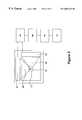
- FIG. 2illustrates a display system in which separate first and second magnification optics are used.
- FIG. 3illustrates the alignment of the second optical axis relative to the first optical axis such that the source object produced by the microdisplay is within the full field of view of the compound magnified virtual image.
- FIGS. 4A-Dillustrate a series of beamsplitting magnification optics which may be used as the beamsplitting magnification.
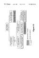
- FIG. 5illustrates the electronics included within the display system for controlling the microdisplay.
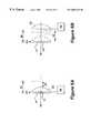
- FIGS. 6A-Billustrate an expandable and contractible display system including a beamsplitting magnification optic and a reflective element in which FIG. 6A illustrates the display system in its contracted state and FIG. 6B illustrates the display system in its expanded state.
- FIG. 7illustrates a display system in which a waveguide is used to illuminate a light transmissive microdisplay.
- FIG. 8illustrates a display system in which a waveguide is used to illuminate a light transmissive microdisplay.
- FIG. 9illustrates a display system in which a light emitting diode is used as the illumination source.
- FIGS. 10A-Billustrates an alternate embodiment of the display system in which FIG. 10A illustrates the use of quarter wave guides to prevent light not constituting the compound magnified virtual image from reaching the observer and FIG. 10B illustrates the light emitting diode used in the display.
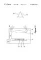
- FIG. 11illustrates an embodiment of the display system which includes an eye position sensor system which enables the observer to use his or her eye to interact with a control device to control the source object produced by the microdisplay and/or functions that the display system performs.
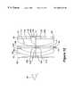
- FIG. 12illustrates a preferred embodiment of the display system of the present invention in which a single beamsplitting magnification optic is employed.
- FIG. 13illustrates what happens to the portions of the light corresponding to the source object 14 which are reflected or transmitted by the beamsplitting magnification optic 33 in the display system illustrated in FIGS. 10A-D.
- the present inventionrelates to an inexpensive, compact virtual image electronic display including a first and a second magnification optic which provide a compound magnified virtual image of a source object formed by a microdisplay where one of the magnification optics is reflective and is used to fold the optical train of the display onto itself, thereby enabling the display system to be housed in a compact volume.
- FIG. 1illustrates a particularly preferred embodiment of the display system in which a single beamsplitting magnification optic is employed as both first and second magnification optic.
- the virtual image electronic display system 10includes a beamsplitting magnification optic 33 and a microdisplay 12 for producing a source object 14 .
- the magnification opticIn general, in order for a magnification optic to magnify a source object, the magnification optic must be positioned some distance away from the source object.
- the microdisplayWhen a single beamsplitting magnification optic is used, the microdisplay is positioned away from the beamsplitting magnification optic and in the proximity with the reflective element 31 .
- the microdisplay 12is preferably positioned between about 3 and 15 mm from the beamsplitting magnification optic 33 , more preferably between about 5 and 10 mm from the beamsplitting magnification optic 33 . It is also preferred that the microdisplay 12 be positioned adjacent the reflective surface 37 of the reflective element 31 opposite the beamsplitting magnification optic 33 , the reflective surface 37 providing a convenient support structure on which to mount the microdisplay 12 .
- the centerpoint 13 of microdisplay 12 and the centerpoint 15 of the beamsplitting magnification optic 33define a first optical axis 18 centered along which the source object 14 is projected toward the beamsplitting magnification optic 33 .
- the beamsplitting magnification optic 33Incorporated into the beamsplitting magnification optic 33 is a magnification function and a reflection function such that the beamsplitting magnification optic 33 images the source object 14 and reflects a magnified virtual image 20 of the source object 14 toward the reflective element 31 .
- the center of the imaging rays 22 forming the reflected magnified virtual image 20define a second optical axis 24 that is at an angle ⁇ relative to the first optical axis 18 .
- the angle ⁇ between the first and second optical axesis equal to or less than about 40° and is preferably equal to or less than about 10° and more preferably equal to or less than about 5°.
- the beamsplitting magnification optic 33also serves as the second transmissive magnification optic in the display system. More specifically, the imaging rays 22 forming the reflected magnified virtual image 20 are reflected off the reflective element 31 back toward the beamsplitting magnification optic 33 which then magnifies the magnified virtual image 20 to produce a compound magnified virtual image 28 of the source object 14 to an observer 30 .
- Display systems as illustrated in FIG. 1 where a beamsplitting magnification optic 33 is used as both a first and a second magnification opticare optically equivalent to an alternate embodiment of the invention illustrated in FIG. 2 in which separate first and second magnification optics are used.
- Display systems according to FIG. 2have previously been described in detail in “Compact Compound Magnified Virtual Image Electronic Display,” application Ser. No. 08/407,102; Filed: Mar. 17, 1995, which is incorporated herein by reference.
- the display systemincludes a microdisplay 12 for producing a source object 14 and a first magnification optic 16 positioned along a first optical axis 18 , the first optical axis being defined by the centerpoint 13 of microdisplay 12 and the centerpoint 15 of the first magnification optic 16 .
- the source object 14is projected toward the first magnification optic 16 and is centered upon the first optical axis 18 .
- the microdisplay 12is positioned adjacent, i.e., within about 3 mm, of either the proximal 32 or distal 34 refractive surface of the second magnification optic 26 .
- the first magnification optic 16Incorporated into the first magnification optic is a magnification function and a reflection function such that the first magnification optic 16 images the source object 14 and provides a magnified virtual image 20 of the source object 14 in the direction of the observer 30 .
- the center of the imaging rays 22 forming the magnified virtual image 20define a second optical axis 24 that is at an angle ⁇ relative to the first optical axis 18 .
- the displacement angle 100 of the second optical axis 24 relative to the first optical axis 18is equal to twice the tilt angle of the normal to the center of curvature of the first magnification optic if the optic is tilted.
- the displacement angle ⁇is also equal to twice the distance of the normal to the center of curvature of the first magnification optic 16 divided by the radius of curvature of the first magnification optic 16 if the first magnification optic 16 is off center.
- the virtual image electronic display systemalso includes a second magnification optic 26 which receives the magnified virtual image 20 and provides a compound magnified virtual image 28 of the source object 14 to the observer 30 within the full field of view.
- the electronic displayalso includes an intermediate image synthesizing optic which provides a synthesized electronic display with enhanced eye relief and a wider field of view than is possible using a traditional compound magnification system.
- the synthesized electronic displayenables the observer to view the display over a 34 degree full angle field of view with at least about a 35 mm eye relief.
- the image synthesizing optic 42should be positioned at or adjacent to the source object plane.
- the image synthesizing optic 42is preferably positioned adjacent to or integrally incorporated into the microdisplay 12 .
- the image synthesizing optic 42may be any optic which produces a directly viewable image when placed in the source object plane of a magnification optic.
- the image synthesizing optic 42is preferably designed such that a large fraction of the light is redirected so that the entirety of the image remains visible as the eye is moved laterally relative to the second stage magnification optic 26 .
- the numerical aperture of the directed lightis preferably on the order of the (radius of the second stage magnification optic)/(focal length of the second stage magnification optic).
- reflective element 31creates a virtual beamsplitting magnification optic, depicted in dashed lines as element 35 .
- This virtual beamsplitting magnification optic 35is in roughly the same position as the first magnification optic 16 illustrated in FIG. 2 .
- use of the reflective element 31in combination with the beamsplitting magnification optic 33 , enables the beamsplitting magnification optic 33 to function as both the first and second magnification optic as described in application Ser. No. 08/407,102.
- the partially reflective optic 33serves as its own complementary optic, cancelling out many of the aberrations introduced into the image by the first stage of magnification during the second stage of magnification.
- the compound magnified virtual image producedis substantially free of aberrations.
- the use of a single beamsplitting magnification opticalso provides the advantage that the optical train is folded onto itself a second time. As a result, the spacing between the components employed in the embodiment of the synthesized display illustrated in FIG. 1 is further reduced over that which is achieved using separate first and second magnification optics. For example, by using a reflective element 31 in combination with the beamsplitting magnification optic 33 , the thickness of the display system along the first optical axis may be reduced to less than about 15 mm and preferably less than about 7 mm.
- the second optical axisis preferably aligned relative to the first optical axis as illustrated in FIG. 3 such that the source object 14 produced by the microdisplay 12 is within the full field of view 25 of the second magnification optic 26 .
- “Full field of view,” as the term is used herein,is intended to indicate that if one were to block a portion of the field of view 25 illustrated in FIG.
- the full field of viewnonetheless refers to the entire circular field of view as illustrated in FIG. 3 .
- the angle between the first and second optical axesis equal to or less than about 10° and more preferably equal to or less than about 5°. At these smaller angles, the amount of aberrations in the compound magnified virtual image are significantly reduced.
- the electronic display systems of the present inventionpreferably provide an eye relief equal to or greater than about 15 mm, more preferably equal to or greater than about 25 mm, most preferably equal to or greater than about 35 mm.
- the electronic displayalso preferably provides an image which is at least equivalent in size to a computer monitor (24 cm ⁇ 18 cm) when viewed at 50 cm. This size is roughly equivalent to a large screen TV (100 cm diagonal) when viewed at 165 cm.
- the electronic displayalso preferably provides about a 34° field of view (17° to either side of the central optical axis).
- the beamsplitting magnification opticWhen a single beamsplitting magnification optic is employed, the beamsplitting magnification optic preferably provides a compound magnified virtual image that is magnified by a factor of at least 10 relative to the source object, more preferably a factor of at least 20.
- the beamsplitting magnification opticalso preferably has a focal length between about 25 mm and 100 mm. It is also preferred that the beamsplitting magnification optic be between about 25% and 75% reflective, most preferably about 50% reflective.
- the beamsplitting magnification opticmay include a simple single optic as illustrated in FIG. 1 .
- more complex opticsmay be used as the beamsplitting magnification optic and are intended to fall within the scope of the present invention.
- FIGS. 4A-Dillustrate a series of optical designs which may be incorporated into the beamsplitting magnification optic in the display systems of the present invention. It should be understood that the series of optical designs illustrated in FIGS. 4A-D are in no way exhaustive of the different optical designs that may be used.
- FIG. 4Aillustrates an additional optical element 80 being inserted between the beamsplitting magnification optic 33 and the reflective element 31 .
- FIG. 4Billustrates an additional optical element 80 where the reflective element 31 has been integrally incorporated into the additional optical element 80 .
- FIG. 4Cillustrates an optical system similar to the optical system illustrated in FIG. 4B except that an additional optical element 82 has been inserted into the system.
- FIG. 4Dillustrates an optical system where an additional optical element 84 has been added after the beamsplitting magnification optic 33 .
- the additional optical elements in all of the optical systems illustrated in FIGS. 4A-Dcan be used to correct optical aberrations including field curvature, coma, astigmatism and distortion.
- the shapes of the surfaces of the optical elementscan be any aspheric optical surface.
- the optical materials used to form the optical elementscan be different for the different optical elements.
- the electronic display systems of the present inventionare intended as inexpensive electronic components which may be incorporated into any electronic device in which an electronic display is used.
- the display systemis designed for use in pocket-sized electronic devices. Examples of such devices include, but are not limited to, portable computers, personal communicators, personal digital assistants, modems, pagers, video and camera viewfinders, mobile phones, television monitors and other hand held devices.
- a beamsplitting magnification optic 33When a beamsplitting magnification optic 33 is used in place of separate first and second magnification optics, as illustrated in FIG. 1, only a portion of the light forming the magnified virtual image is reflected by the optic.
- the beamsplitting magnification optic 33images the source object 14 and reflects a magnified virtual image 20 toward the reflective element 31 , a portion of the light is transmitted through the beamsplitting magnification optic 33 toward the observer 30 , the percentage depending on the beamsplitting optic used.
- the light transmitted through the beamsplitting magnification optic 33is generally not in focus and thus does not interfere with the observer's perception of the compound magnified virtual image 28 , except with regard to contrast ratio.
- the imaging rays 22 forming the reflected magnified virtual image 20are transmitted through the beamsplitting magnification optic 33 as the compound magnified virtual image 28 to the observer 30 .
- the other portion of the lightis reflected by the beamsplitting magnification optic 33 toward the reflective element 31 . This reduces the light intensity of the compound magnified virtual image 28 provided to the observer 30 .
- the display systemmay include additional components which reduce the amount of light transmitted through the beamsplitting magnification optic 33 which does not correspond to the compound magnified virtual image, thereby improving the image contrast ratio provided to the observer by the display system.
- FIG. 5illustrates the electronics included within the display system for controlling the microdisplay.
- the microdisplay 12includes an input 52 which is electronically attached by electrodes 68 to the microdisplay 12 . Also connected to the input 52 is a control device 54 for conveying electrical signals through the input to control the generation of the source object 14 .
- the control device 54may also be connected to a logic processor 66 which is also connected to external memory 70 which may be controlled through an external data source 72 .
- the microdisplay 12is a row-column addressed display system.
- the microdisplay 12is connected to the input 52 such as shift registers through optically transparent electrodes 68 such as indium tin oxide or any other suitable optical transparent conducting material.
- the input 52 , shift registersare connected to a control device 54 such as a character generator with timing and decoding logic.
- the control device 54is controlled by a processor 66 which manipulates the data from the external memory 70 .
- the external memoryreceives the information from the external data source 72 such as an external radio receiver.
- the external data source 72could also be infrared diode data link to another computer, LAN system, or any other device capable of sending analog or digital communications.
- the external memory 70 and external data source 72is a separate PCMCIA card which can be connected to a computer or communication system.
- the display systems of the present inventioncan be modified to be expandable and contractible along the first optical axis 18 .
- the display systemcan be contracted such that the beamsplitting magnification optic 33 is brought in contact with the reflective element 31 .
- the display systemcan be expanded by increasing the distance 25 between the beamsplitting magnification optic 33 and the reflective element 31 .
- the display systemmay be designed such that there are a series of distances D 1 -D i at which the beamsplitting magnification optic 33 may be positioned relative to the reflective element 31 .
- the distance 25 between the beamsplitting magnification optic 33 and the reflective element 31can be adjusted to any distance between D 1 and D i .
- the display systemWhen the display system is in a contracted state, eye relief provided by the display system is maximized. However, the magnification provided by the display system is reduced. As the display system is expanded, the magnification provided by the display system increases and the eye relief decreases. The adjustability of the separation between the beamsplitting magnification optic 33 and the reflective element 31 thus provides the observer with the ability to adjust the magnification and ergonomics of the display system.
- the display systempreferably includes a distance adjusting mechanism which adjusts the distance between the beamsplitting magnification optic 33 and the reflective element 31 .
- the distance adjusting mechanismis preferably controllable by the observer.
- the display systemalso preferably includes a distance sensing mechanism which senses the distance 25 between the beamsplitting magnification optic 33 and the reflective element 31 and conveys a control signal to the control device 54 indicating the distance. Information regarding the distance between the beamsplitting magnification optic 33 and the reflective element 31 can then be employed by the control device 54 to modulate the source object formed by the microdisplay. For example, the sensed distance between the beamsplitting magnification optic 33 and the reflective element 31 can be used by the control device 54 to modulate the size of the characters formed by the microdisplay since the distance 25 dictates the magnification of the source object 14 provided by the display system.
- Modulation of the source objectmay be performed automatically or in response to a control signal provided by the observer (e.g., the observer presses a button).
- the display systemmay include a control mechanism which enables the observer to modify the size of the source object by sending a control signal to the control device.
- Modulation of the magnification and focus of the display systemmay also be performed automatically or in response to a control signal provided by the observer.
- the display systemmay include a control mechanism which enables the observer to control the distance adjusting mechanism, thereby controlling the distance between the first and second magnification optics.
- the microdisplay 12 used in the display system 10 of the present inventionmay be any electronically activated display which can produce a source object of any type.
- the microdisplaymay be a liquid crystal display, a spatial light modulator, a grating, a mirror light valve or a LED array.
- Microdisplaysmay generally divided into two categories, reflective and light transmissive displays.
- the microdisplayWhen the microdisplay is reflective, the microdisplay does not permit light to pass through the display. Therefore, when a reflective microdisplay is positioned within the full field of view, one must look around the microdisplay in order to see the compound magnified virtual image. When the microdisplay is larger than the pupil size of the eye, generally between about 3-7 mm, substantial vignetting of the compound magnified virtual image can occur. It is therefore preferred that the reflective microdisplay be as small as possible, preferably equal to or less than 49 mm 2 and more preferably equal to or less than 9 mm 2 .
- a scattering mode liquid crystal displayis an example of a substantially light transmissive microdisplay.
- the microdisplay 12preferably produces a source object having a surface area equal to or less than about 25 mm 2 , most preferably equal to or less than about 9 mm 2 .
- microdisplayswhich can produce larger source objects may be employed.
- the microdisplay 12form a source object 14 using an array of pixels 11 on the microdisplay 12 wherein each pixel has an area equal to or less than about 1600 square microns, more preferably equal to or less than about 25 square microns.
- the microdisplay 12 used to form the source object 14is a spatial light modulator.
- Spatial light modulatorsalso known as light valves, are well known in the art for use in electronic display systems.
- a spatial light modulatorincludes an addressable array of light modulating mirror elements which modulate incident light in a spatial pattern to produce an image.
- the array of modulating elementsare modulated in response to an electrical or optical input where each light modulating element corresponds to a pixel of the image generated by the light modulator.
- Incident lightmay be modulated by the modulating elements with regard to phase, intensity, polarization, or direction.
- Light modulationmay be achieved using a variety of materials exhibiting electrooptic or magnetooptic effects and by materials that modulate light by surface deformation.
- the microdisplaybe a reflective spatial light modulator.
- the microdisplayis a light transmissive microdisplay.
- a light transmissive microdisplayis any electronically activated display which produces an image of any type which, when light is transmitted through the microdisplay, some fraction of the light passing through the display is not modulated by either phase, polarization, direction or intensity.
- a number of liquid crystal displaysmodulate the polarization of light.
- the liquid crystal displayis a cholesteric-nematic phase transition liquid crystal display. This type of display scatters some of the light through the display.
- the imaging rays 22 forming the magnified virtual image 20are preferably arranged in such a manner that the second optical axis is aligned relative to the first optical axis such that the source object 14 produced by the microdisplay 12 is within the field of view 25 of the compound magnified virtual image 28 .
- the observereffectively looks through the microdisplay to visualize the compound magnified virtual image 28 because the microdisplay 12 is positioned in the near field of the observer's vision when the observer is focusing on the compound magnified virtual image 28 positioned in the observer's far field of vision.
- Illuminationis generally required to project the source object 14 formed by the microdisplay 12 onto the magnification optic.
- the microdisplayis a light transmissive microdisplay
- illuminationis provided from the rear of the microdisplay.
- the microdisplayis a reflective, illumination is provided so that the illumination is reflected off the imaging surface of the microdisplay onto the optic serving as the first magnification optic.
- an optical wave guide 17may be formed by two glass plates 19 which are also used to form a cholesteric-nematic phase transition liquid crystal display microdisplay 12 .
- Illuminationis introduced into the wave guide 17 at one side 21 of the glass plates 19 by an illumination source 23 .
- the illumination introduced into the wave guide 17is then scattered by the cholesteric-nematic phase transition liquid crystal display such that some of the illumination is directed toward the beamsplitting magnification optic 33 .
- Illuminationmay also be provided to a light transmissive microdisplay using a direct light source, such as a light emitting diode, positioned behind the light transmissive microdisplay.
- a direct light sourcesuch as a light emitting diode
- an optical wave guide 17may be formed by two glass plates 19 . Illumination is introduced into the wave guide 17 at one side 21 of the glass plates 19 by an illumination source 23 .
- the waveguideis designed to direct illumination toward the reflective microdisplay 12 .
- FIG. 9An alternate approach to providing illumination to a reflective microdisplay is through the use of a direct light source, such as a light emitting diode the use of a light emitting diode as an illumination source for a reflective microdisplay is illustrated in FIG. 9 .
- the display systemincludes a beamsplitting magnification optic 33 , a reflective element 31 and a microdisplay 12 .
- a light emitting diode 52is embedded in a glass spacer 54 , the light emitting diode 52 being arranged to direct light toward the reflective microdisplay 12 .
- the beamsplitting magnification optic 33transmits and reflects a percentage of the light, the precise percentage depending on the optic used. It is preferred that the beamsplitting magnification optic 33 reflect between about 25 and 75 percent of the light, more preferably about 40 and 60 percent of the light.
- FIGS. 10A-Billustrate one embodiment of the present invention in which a series of quarter wave plates are used in combination with vertical polarizers to improve the contrast ratio of the display system.
- the display system illustrated in FIG. 10Aincludes a beamsplitting magnification optic 33 , a reflective optic 31 , a microdisplay 12 , and a light emitting diode 52 embedded in a glass spacer 54 as illustrated with regard to FIG. 9 .
- the light emitting diode 52includes a vertical polarizer 56 and an aluminum mirror 58 such that the light emitting diode 52 provides vertically polarized illumination.
- a quarter waveplate 60is positioned between the beamsplitting magnification optic 33 and the reflective optic 31 .
- a polarizer 62is positioned between the beamsplitting magnification optic 33 and the observer 30 which only allows vertically polarized light to pass.
- the vertical polarizer 56converts the light emitted from the light emitting diode 52 into vertically polarized light.
- the lightis then passed through a quarter waveplate which converts the light into right or left circularly polarized light.
- This lightis then reflected off of the reflective microdisplay 12 to form a source object 14 which is projected toward the beamsplitting magnification optic 33 .
- the light corresponding to the source object 14passes through the quarter waveplate 60 again which converts the light into horizontally polarized light.
- the portion of the light reflected off the beamsplitting magnification optic 33 toward the reflective element 31 as the magnified virtual image 20traverses the quarter waveplate 60 which converts the light into right or left circularly polarized light.
- the quarter waveplate 60Once past the quarter waveplate 60 , the light reflected off the reflective element 31 where it again traverses the quarter waveplate 60 , the quarter waveplate 60 converting right or left circularly polarized light into vertically polarized light.
- the vertically polarized light corresponding to the magnified virtual image 20reaches the beamsplitting magnification optic 33 where a portion of the light is reflected back toward the reflective element 31 .
- a second portion of the lightis magnified as it traverses the beamsplitting magnification optic 33 and forms a compound magnified virtual image 20 of the source object 14 .
- the light traversing the beamsplitting magnification optic 33is vertically polarized light and is thus able to traverse the polarizer 62 and reach the observer 30 as the compound magnified virtual image 20 .
- Table 1summarizes what happens to the portions of the light corresponding to the source object 14 which are reflected or transmitted by the beamsplitting magnification optic 33 in the display system illustrated in FIGS. 10A-D.
- the display system as illustrated in FIGS. 10A-Dprovides a contrast ratio of the compound magnified image to unfocused background light of 4:1.
- the light transmitted through the beamsplitting magnification optic 33 that does not correspond to the imageis not in focus and thus does not interfere with the observer's perception of the compound magnified virtual image 28 , except with regard to the contrast ratio.
- the electronic displaymay also include an intermediate image synthesizing optic which provides a synthesized electronic display with enhanced eye relief and a wider field of view than is possible using a traditional compound magnification system.
- the synthesized electronic displayenables the observer to view the display over a 34 degree full angle field of view with at least about a 35 mm eye relief.
- the display systemincludes an eye position sensor system which enables the observer to use his or her eye to interact with a control device. Through this interaction, the eye position sensor system may be used to control the source object produced by the microdisplay.
- the eye position sensor systemmay also be used to control a variety of functions performed by the display system, for example, directing a printer to print a document or directing a facsimile machine to send a message.
- the position of the observer's eyeis detected and used, much like a cursor, to interact with the controlling device 54 to control the source object 14 produced by the microdisplay 12 .
- Devicessuch as eye trackers and occulometers, for detecting the position of the eye, are well known in the art.
- suitable deviceswhich may be used in conjunction with the virtual mouse sensor system include the devices described in United Kingdom Patent Application GB 2270171A and U.S. Pat. No. 4,513,317, each of which is incorporated herein by reference.
- the eye position sensor system 56includes a light emitting diode (LED) 58 positioned around the perimeter of the beamsplitting magnification optic 33 for providing illumination in the direction of the observer's eye 30 .
- the illuminationis preferably in the infrared region.
- the eye position sensor system 56also includes a detector array 60 positioned adjacent to the beamsplitting magnification optic 33 for detecting reflections of the illumination from the LED 58 off of the retina 62 of the observer's eye 30 , the reflections serving to indicate the position of the observer's eye 30 .
- the eye position sensor system 56also includes a control mechanism 64 which the observer uses in combination with the detector array 60 to interact with the controlling device 54 to control the source object 14 produced by the microdisplay 12 .
- the control mechanism 64may be, for example, a button which the observer 30 depresses to indicate that the observer is looking at a selected item, such as a computer software icon.
- the control mechanism 64may also be a timing mechanism which determines that the observer has selected an item based on the amount of time that the observer is looking in a particular direction.
- FIG. 12illustrates a preferred embodiment of the display system of the present invention in which a beamsplitting magnification optic is employed.
- the virtual image display system illustrated in FIG. 12includes a beamsplitting magnification optic 33 , a lens 80 and a reflective element 31 similar to those elements illustrated in FIG. 4 B.
- Also included in the virtual image display systemis a wave guide illumination source 17 , a reflective microdisplay 12 and three polarization elements 56 , 60 and 62 .
- the beamsplitting magnification optic 33is made from glass with an index of refraction of 1.51 such as BK7 or a similar type of glass.
- the beamsplitting magnification optic 33has a thickness 100 of 0.08 inches and a diameter of 0.9 inches.
- a first surface 96 of the beamsplitting magnification optic 33 facing the eye 30has a radius of curvature equal to 1.15 inches.
- a second surface 98 of the beamsplitting magnification optic 33 facing away from the eye 30has a radius of curvature equal to 0.823 inches.
- a partially reflective beamsplitter coating 102 in the visible wavelength regimeis applied to the first surface 96 .
- the second surface 98includes an anti-reflection coating 104 for visible wavelengths.
- the polarization element positioned nearest the eye 30is a sheet polarizer 62 such as is available from the Polaroid Corporation.
- the wave guide illumination source 17includes an LED 23 which provides illumination to the reflective microdisplay 12 .
- the output of the LED 23is polarized by a polarizer 56 , thereby illuminating the reflective microdisplay 12 with polarized light.
- the wave guide illumination source 17has a thickness 106 of 0.04 inches.
- the distance 108 between the beamsplitting magnification optic 33 and the wave guide illumination source 17is 0.1209 inches.
- Lens 80is positioned a distance 110 of 0.005 inches from the wave guide 17 .
- Lens 80is made from glass with an index of refraction of 1.51 such as BK7 or a similar type of glass.
- Lens 80has a first surface 112 facing the eye 30 with a radius of curvature of 1.02 inches and a second flat surface 114 .
- the first surface 112is anti-reflection coated for visible wavelengths.
- the second surface 114is uncoated.
- Lens 80has a thickness 116 of 0.210 inches and a diameter of 0.9 inches.
- a quarter waveplate 60 in the visible wavelength regimesuch as is available from Virgo Optics in Port Richey, Fla., is positioned in contact with lens 80 .
- the quarter waveplate 60has a thickness 118 of 0.04 inches.
- the quarter waveplate 60includes a first surface 120 facing the eye which is uncoated and a second surface 122 facing away from the eye 30 which is coated with aluminum or other suitable reflective material except for a small rectangular region 124 in the center of the waveplate where the reflective microdisplay 12 is positioned.
- the first uncoated surface 120 of the quarter waveplate 60is placed in optical contact with lens 80 using a suitable transparent optical cement.
- the display 12is placed in contact with the uncoated rectangular region 124 of the quarter waveplate.
Landscapes
- Physics & Mathematics (AREA)
- General Physics & Mathematics (AREA)
- Optics & Photonics (AREA)
- Spectroscopy & Molecular Physics (AREA)
- Lenses (AREA)
- Image Generation (AREA)
Abstract
Description

Claims (32)
Priority Applications (1)
| Application Number | Priority Date | Filing Date | Title |
|---|---|---|---|
| US09/182,951US6603443B1 (en) | 1994-12-21 | 1998-10-29 | Compact display system controlled by eye position sensory system |
Applications Claiming Priority (5)
| Application Number | Priority Date | Filing Date | Title |
|---|---|---|---|
| US08/361,035US5644323A (en) | 1994-12-21 | 1994-12-21 | Miniature synthesized virtual image electronic display |
| US08/407,102US5625372A (en) | 1994-12-21 | 1995-03-17 | Compact compound magnified virtual image electronic display |
| US08/441,529US5684497A (en) | 1994-12-21 | 1995-05-15 | Twice folded compound magnified virtual image electronic display |
| US08/831,106US5870068A (en) | 1994-12-21 | 1997-04-01 | Twice folded compound magnified virtual image electronic display |
| US09/182,951US6603443B1 (en) | 1994-12-21 | 1998-10-29 | Compact display system controlled by eye position sensory system |
Related Parent Applications (1)
| Application Number | Title | Priority Date | Filing Date |
|---|---|---|---|
| US08/831,106ContinuationUS5870068A (en) | 1994-12-21 | 1997-04-01 | Twice folded compound magnified virtual image electronic display |
Publications (1)
| Publication Number | Publication Date |
|---|---|
| US6603443B1true US6603443B1 (en) | 2003-08-05 |
Family
ID=27408496
Family Applications (4)
| Application Number | Title | Priority Date | Filing Date |
|---|---|---|---|
| US08/441,529Expired - LifetimeUS5684497A (en) | 1994-12-21 | 1995-05-15 | Twice folded compound magnified virtual image electronic display |
| US08/831,106Expired - LifetimeUS5870068A (en) | 1994-12-21 | 1997-04-01 | Twice folded compound magnified virtual image electronic display |
| US08/831,371Expired - LifetimeUS5905478A (en) | 1994-12-21 | 1997-04-01 | Twice folded compound magnified virtual image electronic display |
| US09/182,951Expired - LifetimeUS6603443B1 (en) | 1994-12-21 | 1998-10-29 | Compact display system controlled by eye position sensory system |
Family Applications Before (3)
| Application Number | Title | Priority Date | Filing Date |
|---|---|---|---|
| US08/441,529Expired - LifetimeUS5684497A (en) | 1994-12-21 | 1995-05-15 | Twice folded compound magnified virtual image electronic display |
| US08/831,106Expired - LifetimeUS5870068A (en) | 1994-12-21 | 1997-04-01 | Twice folded compound magnified virtual image electronic display |
| US08/831,371Expired - LifetimeUS5905478A (en) | 1994-12-21 | 1997-04-01 | Twice folded compound magnified virtual image electronic display |
Country Status (7)
| Country | Link |
|---|---|
| US (4) | US5684497A (en) |
| EP (1) | EP0799435B1 (en) |
| JP (1) | JP3206920B2 (en) |
| AT (1) | ATE182691T1 (en) |
| AU (1) | AU4603296A (en) |
| DE (1) | DE69511114D1 (en) |
| WO (1) | WO1996019746A2 (en) |
Cited By (11)
| Publication number | Priority date | Publication date | Assignee | Title |
|---|---|---|---|---|
| US20030086062A1 (en)* | 1999-12-23 | 2003-05-08 | Shevlin Technologies Limited | Display device |
| US20050286135A1 (en)* | 2004-02-04 | 2005-12-29 | Paul Weissman | Compact electronic viewfinder |
| US7108378B1 (en) | 2001-01-29 | 2006-09-19 | Maguire Jr Francis J | Method and devices for displaying images for viewing with varying accommodation |
| US7490936B2 (en)* | 2003-08-15 | 2009-02-17 | E-Vision Llc | Enhanced electro-active lens system |
| US20120113097A1 (en)* | 2010-11-05 | 2012-05-10 | Samsung Electronics Co., Ltd. | Display apparatus and method |
| US20150185507A1 (en)* | 2005-10-07 | 2015-07-02 | Percept Technologies Inc. | Digital eyewear |
| US9429756B1 (en) | 2013-06-27 | 2016-08-30 | Google Inc. | Transparent microdisplay in head mountable displays |
| US9563331B2 (en) | 2013-06-28 | 2017-02-07 | Microsoft Technology Licensing, Llc | Web-like hierarchical menu display configuration for a near-eye display |
| US9658473B2 (en) | 2005-10-07 | 2017-05-23 | Percept Technologies Inc | Enhanced optical and perceptual digital eyewear |
| US10962789B1 (en) | 2013-03-15 | 2021-03-30 | Percept Technologies Inc | Digital eyewear system and method for the treatment and prevention of migraines and photophobia |
| US11428937B2 (en) | 2005-10-07 | 2022-08-30 | Percept Technologies | Enhanced optical and perceptual digital eyewear |
Families Citing this family (30)
| Publication number | Priority date | Publication date | Assignee | Title |
|---|---|---|---|---|
| US5684497A (en)* | 1994-12-21 | 1997-11-04 | Siliscape, Inc. | Twice folded compound magnified virtual image electronic display |
| US5644323A (en)* | 1994-12-21 | 1997-07-01 | Siliscape, Inc. | Miniature synthesized virtual image electronic display |
| US5970418A (en)* | 1995-09-21 | 1999-10-19 | International Business Machines Corporation | Personal communicator including a handset phone with an integrated virtual image display |
| JPH0991397A (en)* | 1995-09-25 | 1997-04-04 | Nec Corp | Separation type pc card |
| US5771124A (en)* | 1996-07-02 | 1998-06-23 | Siliscape | Compact display system with two stage magnification and immersed beam splitter |
| US6433935B2 (en) | 1996-07-02 | 2002-08-13 | Three-Five Systems, Inc. | Display illumination system |
| EP0818701B1 (en)* | 1996-07-09 | 2002-10-02 | Harness System Technologies Research, Ltd. | Display device |
| US6069608A (en)* | 1996-12-03 | 2000-05-30 | Sony Corporation | Display device having perception image for improving depth perception of a virtual image |
| JPH10282448A (en)* | 1997-04-04 | 1998-10-23 | Minolta Co Ltd | Display |
| US6191759B1 (en)* | 1997-12-02 | 2001-02-20 | Gregory J. Kintz | Virtual reality system with a static light emitting surface and magnifying optical system |
| US6097353A (en)* | 1998-01-20 | 2000-08-01 | University Of Washington | Augmented retinal display with view tracking and data positioning |
| US6094181A (en)* | 1998-02-02 | 2000-07-25 | Inviso, Inc. | Miniature synthesized virtual image electronic display |
| US5991084A (en)* | 1998-02-04 | 1999-11-23 | Inviso | Compact compound magnified virtual image display with a reflective/transmissive optic |
| WO2000028370A1 (en)* | 1998-11-06 | 2000-05-18 | Kopin Corporation | Microdisplay viewer |
| CA2386856A1 (en) | 1999-10-14 | 2001-04-19 | Stratos Product Development Llc | Virtual imaging system |
| US6222686B1 (en)* | 1999-10-22 | 2001-04-24 | Motorola, Inc. | Gradient index magnifying lens |
| JP2001217908A (en)* | 2000-01-31 | 2001-08-10 | Nec Corp | Portable wireless unit |
| FR2815422B1 (en)* | 2000-10-13 | 2003-09-19 | Commissariat Energie Atomique | INDIVIDUAL VISUALIZATION SYSTEM |
| US7048631B2 (en)* | 2001-09-28 | 2006-05-23 | Igt | Gaming device having a game with a functional refractive light display |
| JP2010521700A (en)* | 2007-03-15 | 2010-06-24 | スイス メディカル テヒノロギー ゲーエムベーハー | Magnifying magnifier with aspheric lens |
| US8982014B2 (en) | 2012-02-06 | 2015-03-17 | Battelle Memorial Institute | Image generation systems and image generation methods |
| US9076368B2 (en) | 2012-02-06 | 2015-07-07 | Battelle Memorial Institute | Image generation systems and image generation methods |
| US10345903B2 (en)* | 2013-07-30 | 2019-07-09 | Microsoft Technology Licensing, Llc | Feedback for optic positioning in display devices |
| US9851070B2 (en) | 2013-09-09 | 2017-12-26 | Wavefront Technology, Inc. | Systems and methods to impart visual quality to illumination systems |
| US20150277841A1 (en)* | 2014-03-27 | 2015-10-01 | Microsoft Corporation | Multi mode display system |
| NZ773836A (en) | 2015-03-16 | 2022-07-01 | Magic Leap Inc | Methods and systems for diagnosing and treating health ailments |
| KR102069024B1 (en)* | 2015-09-03 | 2020-01-22 | 쓰리엠 이노베이티브 프로퍼티즈 컴파니 | Optical system |
| IL311431A (en)* | 2017-02-23 | 2024-05-01 | Magic Leap Inc | Display system with variable power reflector |
| CN110959132B (en)* | 2017-05-27 | 2022-06-14 | 李汶基 | Glasses type display and variable focal length glasses type display |
| EP4453634A4 (en)* | 2021-12-20 | 2025-10-15 | Magic Leap Inc | Method and system for performing optical imaging in augmented reality devices |
Citations (90)
| Publication number | Priority date | Publication date | Assignee | Title |
|---|---|---|---|---|
| US3296509A (en) | 1965-11-12 | 1967-01-03 | Gen Electric | Capacitor with polyphenylene oxide dielectric |
| US3758196A (en) | 1971-04-12 | 1973-09-11 | H Weiss | Optical magnifying system and apparatus for viewing small objects |
| US4082440A (en) | 1975-10-14 | 1978-04-04 | Gaf Corporation | Compact microform reader |
| US4082432A (en) | 1975-01-09 | 1978-04-04 | Sundstrand Data Control, Inc. | Head-up visual display system using on-axis optics with image window at the focal plane of the collimating mirror |
| US4099831A (en) | 1971-11-29 | 1978-07-11 | Vision Engineering, Ltd. | High magnification optical apparatus with rotatable reflective lenticulated surface |
| GB2004383A (en) | 1977-08-29 | 1979-03-28 | Farrand Optical Co Inc | Infinity display system |
| US4361384A (en) | 1980-06-27 | 1982-11-30 | The United States Of America As Represented By The Secretary Of The Army | High luminance miniature display |
| GB2182456A (en) | 1983-09-13 | 1987-05-13 | Secr Defence | Display systems |
| US4717248A (en) | 1985-10-03 | 1988-01-05 | Larussa Joseph | Display system |
| US4728185A (en) | 1985-07-03 | 1988-03-01 | Texas Instruments Incorporated | Imaging system |
| US4832427A (en) | 1987-02-06 | 1989-05-23 | Nippondenso Co., Ltd. | Holographic display system |
| US4859031A (en) | 1987-08-03 | 1989-08-22 | Kaiser Electronics | Optical collimating apparatus |
| US4884219A (en)* | 1987-01-21 | 1989-11-28 | W. Industries Limited | Method and apparatus for the perception of computer-generated imagery |
| EP0351967A2 (en) | 1988-07-06 | 1990-01-24 | Kaiser Aerospace And Electronics Corporation | Improved optical combiner collimating apparatus |
| US4900133A (en) | 1988-10-27 | 1990-02-13 | Kaiser Electronics | Heads-up display combiner utilizing a cholesteric liquid crystal element |
| US4925272A (en) | 1988-02-15 | 1990-05-15 | Yazaki Corporation | Indication display unit for vehicles |
| US4934773A (en)* | 1987-07-27 | 1990-06-19 | Reflection Technology, Inc. | Miniature video display system |
| US4969730A (en) | 1988-10-13 | 1990-11-13 | U.S. Philips Corporation | Image projection arrangement |
| US4999012A (en) | 1987-04-16 | 1991-03-12 | Yazaki Corporation | Display apparatus for a vehicle |
| US5035474A (en) | 1984-04-16 | 1991-07-30 | Hughes Aircraft Company | Biocular holographic helmet mounted display |
| US5087116A (en) | 1990-07-27 | 1992-02-11 | Eastman Kodak Company | Reflective image display including a first mirror and a Fresnel mirror |
| US5121099A (en) | 1990-08-31 | 1992-06-09 | Hughes Aircraft Company | Two-page automotive virtual image display |
| US5157503A (en) | 1991-07-16 | 1992-10-20 | Hughes Aircraft Company | Near-infinity image display system |
| US5189512A (en) | 1991-07-01 | 1993-02-23 | Camair Research, Inc. | Helmet integrated display system |
| US5224198A (en) | 1991-09-30 | 1993-06-29 | Motorola, Inc. | Waveguide virtual image display |
| EP0566001A2 (en) | 1992-04-07 | 1993-10-20 | Hughes Aircraft Company | Wide spectral bandwidth virtual image display optical system |
| EP0566002A1 (en) | 1992-04-07 | 1993-10-20 | Hughes Aircraft Company | Ultra-compact, wide field of view virtual image display optical system |
| EP0566000A1 (en) | 1992-04-07 | 1993-10-20 | Hughes Aircraft Company | Virtual image display system |
| US5291338A (en) | 1989-06-15 | 1994-03-01 | Jaeger | Head-down type optical device for delivering information to the driver of a motor vehicle |
| US5303085A (en) | 1992-02-07 | 1994-04-12 | Rallison Richard D | Optically corrected helmet mounted display |
| US5323477A (en) | 1992-08-24 | 1994-06-21 | Motorola, Inc. | Contact array imager with integral waveguide and electronics |
| US5334991A (en) | 1992-05-15 | 1994-08-02 | Reflection Technology | Dual image head-mounted display |
| US5351151A (en) | 1993-02-01 | 1994-09-27 | Levy George S | Optical filter using microlens arrays |
| US5361165A (en) | 1992-01-03 | 1994-11-01 | General Motors Corporation | Reflective cluster display with stowable viewing screen |
| US5369415A (en) | 1992-06-29 | 1994-11-29 | Motorola, Inc. | Direct retinal scan display with planar imager |
| US5383053A (en) | 1992-04-07 | 1995-01-17 | Hughes Aircraft Company | Virtual image display having a high efficiency grid beamsplitter |
| US5386216A (en) | 1992-01-14 | 1995-01-31 | Yazaki Corporation | Indication display unit for vehicles |
| US5394203A (en) | 1994-06-06 | 1995-02-28 | Delco Electronics Corporation | Retracting head up display with image position adjustment |
| US5418584A (en) | 1992-12-31 | 1995-05-23 | Honeywell Inc. | Retroreflective array virtual image projection screen |
| US5422758A (en) | 1993-09-08 | 1995-06-06 | Laser Machining, Inc. | Adjustable beam splitter |
| US5422653A (en) | 1993-01-07 | 1995-06-06 | Maguire, Jr.; Francis J. | Passive virtual reality |
| US5426521A (en) | 1991-12-24 | 1995-06-20 | Research Development Corporation Of Japan | Aberration correction method and aberration correction apparatus |
| US5451976A (en) | 1993-09-14 | 1995-09-19 | Sony Corporation | Image display apparatus |
| US5457575A (en) | 1994-06-20 | 1995-10-10 | Delco Electronics Corporation | Retracting head up display with fine adjustment of combiner |
| US5467104A (en) | 1992-10-22 | 1995-11-14 | Board Of Regents Of The University Of Washington | Virtual retinal display |
| US5467215A (en) | 1994-12-21 | 1995-11-14 | Motorola | Integrated electro-optic package for reflective spatial light modulators |
| US5467205A (en) | 1993-04-28 | 1995-11-14 | Olympus Optical Co., Ltd. | Image display system with right and left eye illuminating means |
| US5477385A (en) | 1992-09-03 | 1995-12-19 | Vision Engineering Limited | Optical magnifying apparatus |
| US5479224A (en) | 1992-12-25 | 1995-12-26 | Olympus Optical Co., Ltd. | Image display apparatus |
| US5483307A (en) | 1994-09-29 | 1996-01-09 | Texas Instruments, Inc. | Wide field of view head-mounted display |
| US5485318A (en) | 1994-10-03 | 1996-01-16 | Motorola, Inc. | Dual image manifestation apparatus with integrated electro-optical package |
| US5486946A (en) | 1994-12-21 | 1996-01-23 | Motorola | Integrated electro-optic package for reflective spatial light modulators |
| US5491491A (en) | 1994-10-31 | 1996-02-13 | Motorola | Portable electronic equipment with binocular virtual display |
| US5499138A (en) | 1992-05-26 | 1996-03-12 | Olympus Optical Co., Ltd. | Image display apparatus |
| US5506728A (en) | 1994-06-10 | 1996-04-09 | Kaiser Aerospace & Electronics Corporation | Dual combiner eyepiece |
| US5506595A (en) | 1985-02-18 | 1996-04-09 | Nissan Motor Co., Ltd. | Vehicular display system forming display image on front windshield |
| US5519536A (en) | 1993-06-16 | 1996-05-21 | Vdo Adolf Schindling Ag | Warning device for displaying information in a vehicle |
| US5526191A (en) | 1991-09-30 | 1996-06-11 | Matsushita Electric Industrial Co., Ltd. | Fourier transform lens assembly |
| US5530586A (en) | 1993-12-07 | 1996-06-25 | Olympus Optical Co., Ltd. | Image display apparatus |
| US5537260A (en) | 1993-01-26 | 1996-07-16 | Svg Lithography Systems, Inc. | Catadioptric optical reduction system with high numerical aperture |
| US5539578A (en) | 1993-03-02 | 1996-07-23 | Olympus Optical Co., Ltd. | Image display apparatus |
| US5539554A (en) | 1994-12-21 | 1996-07-23 | Motorola | Integrated electro-optic package for reflective spatial light |
| US5539422A (en) | 1993-04-12 | 1996-07-23 | Virtual Vision, Inc. | Head mounted display system |
| US5543958A (en) | 1994-12-21 | 1996-08-06 | Motorola | Integrated electro-optic package for reflective spatial light modulators |
| US5546227A (en) | 1993-02-24 | 1996-08-13 | Olympus Optical Co., Ltd. | Image display apparatus |
| US5552934A (en) | 1994-03-18 | 1996-09-03 | Spm Corporation | Background reflection-reducing plano-beam splitter for use in real image projecting system |
| US5552943A (en) | 1990-07-10 | 1996-09-03 | Sony Corporation | Apparatus and method for accessing a location on a magnetic tape |
| US5557353A (en) | 1994-04-22 | 1996-09-17 | Stahl; Thomas D. | Pixel compensated electro-optical display system |
| US5572363A (en) | 1994-11-28 | 1996-11-05 | Fergason; James L. | Retro-reflector based in-line viewing system |
| US5579161A (en) | 1992-11-12 | 1996-11-26 | Olympus Optical Co., Ltd. | Image display apparatus |
| US5579026A (en) | 1993-05-14 | 1996-11-26 | Olympus Optical Co., Ltd. | Image display apparatus of head mounted type |
| US5581271A (en)* | 1994-12-05 | 1996-12-03 | Hughes Aircraft Company | Head mounted visual display |
| US5587836A (en) | 1993-05-13 | 1996-12-24 | Olympus Optical Co., Ltd. | Visual display apparatus |
| US5596433A (en) | 1993-04-27 | 1997-01-21 | Olympus Optical Co., Ltd. | Head-mounted image display apparatus having a prism with an aspherical surface |
| US5596451A (en) | 1995-01-30 | 1997-01-21 | Displaytech, Inc. | Miniature image generator including optics arrangement |
| US5612549A (en) | 1994-03-24 | 1997-03-18 | Motorola | Integrated electro-optical package |
| US5625372A (en)* | 1994-12-21 | 1997-04-29 | Siliscape, Inc. | Compact compound magnified virtual image electronic display |
| US5627678A (en) | 1994-03-15 | 1997-05-06 | Matsushita Electric Industrial Co., Ltd. | Fourier transform optical apparatus and optical information |
| US5638218A (en) | 1993-12-07 | 1997-06-10 | Nikon Corporation | Catadioptric projection apparatus |
| US5644323A (en)* | 1994-12-21 | 1997-07-01 | Siliscape, Inc. | Miniature synthesized virtual image electronic display |
| US5654827A (en) | 1992-11-26 | 1997-08-05 | Elop Electrooptics Industries Ltd. | Optical system |
| US5659430A (en) | 1993-12-21 | 1997-08-19 | Olympus Optical Co., Ltd. | Visual display apparatus |
| US5661604A (en) | 1993-12-22 | 1997-08-26 | Olympus Optical Co., Ltd. | Image display apparatus |
| US5684497A (en)* | 1994-12-21 | 1997-11-04 | Siliscape, Inc. | Twice folded compound magnified virtual image electronic display |
| US5689619A (en)* | 1996-08-09 | 1997-11-18 | The United States Of America As Represented By The Secretary Of The Army | Eyetracker control of heads-up displays |
| US5751260A (en)* | 1992-01-10 | 1998-05-12 | The United States Of America As Represented By The Secretary Of The Navy | Sensory integrated data interface |
| US5886822A (en)* | 1996-10-08 | 1999-03-23 | The Microoptical Corporation | Image combining system for eyeglasses and face masks |
| US5886683A (en)* | 1996-06-25 | 1999-03-23 | Sun Microsystems, Inc. | Method and apparatus for eyetrack-driven information retrieval |
| US6055110A (en)* | 1996-07-02 | 2000-04-25 | Inviso, Inc. | Compact display system controlled by eye position sensor system |
| US6140980A (en)* | 1992-03-13 | 2000-10-31 | Kopin Corporation | Head-mounted display system |
Family Cites Families (1)
| Publication number | Priority date | Publication date | Assignee | Title |
|---|---|---|---|---|
| DE3741886C1 (en)* | 1987-12-10 | 1989-06-29 | Staedtler Fa J S | Writing instrument |
- 1995
- 1995-05-15USUS08/441,529patent/US5684497A/ennot_activeExpired - Lifetime
- 1995-12-20EPEP95944160Apatent/EP0799435B1/ennot_activeExpired - Lifetime
- 1995-12-20ATAT95944160Tpatent/ATE182691T1/enactive
- 1995-12-20JPJP51996696Apatent/JP3206920B2/ennot_activeExpired - Fee Related
- 1995-12-20WOPCT/US1995/016598patent/WO1996019746A2/enactiveIP Right Grant
- 1995-12-20AUAU46032/96Apatent/AU4603296A/ennot_activeAbandoned
- 1995-12-20DEDE69511114Tpatent/DE69511114D1/ennot_activeExpired - Lifetime
- 1997
- 1997-04-01USUS08/831,106patent/US5870068A/ennot_activeExpired - Lifetime
- 1997-04-01USUS08/831,371patent/US5905478A/ennot_activeExpired - Lifetime
- 1998
- 1998-10-29USUS09/182,951patent/US6603443B1/ennot_activeExpired - Lifetime
Patent Citations (95)
| Publication number | Priority date | Publication date | Assignee | Title |
|---|---|---|---|---|
| US3296509A (en) | 1965-11-12 | 1967-01-03 | Gen Electric | Capacitor with polyphenylene oxide dielectric |
| US3758196A (en) | 1971-04-12 | 1973-09-11 | H Weiss | Optical magnifying system and apparatus for viewing small objects |
| US4099831A (en) | 1971-11-29 | 1978-07-11 | Vision Engineering, Ltd. | High magnification optical apparatus with rotatable reflective lenticulated surface |
| US4082432A (en) | 1975-01-09 | 1978-04-04 | Sundstrand Data Control, Inc. | Head-up visual display system using on-axis optics with image window at the focal plane of the collimating mirror |
| US4082440A (en) | 1975-10-14 | 1978-04-04 | Gaf Corporation | Compact microform reader |
| GB2004383A (en) | 1977-08-29 | 1979-03-28 | Farrand Optical Co Inc | Infinity display system |
| US4361384A (en) | 1980-06-27 | 1982-11-30 | The United States Of America As Represented By The Secretary Of The Army | High luminance miniature display |
| GB2182456A (en) | 1983-09-13 | 1987-05-13 | Secr Defence | Display systems |
| US5035474A (en) | 1984-04-16 | 1991-07-30 | Hughes Aircraft Company | Biocular holographic helmet mounted display |
| US5506595A (en) | 1985-02-18 | 1996-04-09 | Nissan Motor Co., Ltd. | Vehicular display system forming display image on front windshield |
| US4728185A (en) | 1985-07-03 | 1988-03-01 | Texas Instruments Incorporated | Imaging system |
| US4717248A (en) | 1985-10-03 | 1988-01-05 | Larussa Joseph | Display system |
| US4884219A (en)* | 1987-01-21 | 1989-11-28 | W. Industries Limited | Method and apparatus for the perception of computer-generated imagery |
| US4832427A (en) | 1987-02-06 | 1989-05-23 | Nippondenso Co., Ltd. | Holographic display system |
| US4999012A (en) | 1987-04-16 | 1991-03-12 | Yazaki Corporation | Display apparatus for a vehicle |
| US4934773A (en)* | 1987-07-27 | 1990-06-19 | Reflection Technology, Inc. | Miniature video display system |
| US4859031A (en) | 1987-08-03 | 1989-08-22 | Kaiser Electronics | Optical collimating apparatus |
| US4925272A (en) | 1988-02-15 | 1990-05-15 | Yazaki Corporation | Indication display unit for vehicles |
| US5050966A (en) | 1988-07-06 | 1991-09-24 | Kaiser Aerospace & Electronics Corporation | Optical combiner collimating apparatus |
| EP0351967A2 (en) | 1988-07-06 | 1990-01-24 | Kaiser Aerospace And Electronics Corporation | Improved optical combiner collimating apparatus |
| US4969730A (en) | 1988-10-13 | 1990-11-13 | U.S. Philips Corporation | Image projection arrangement |
| US4900133A (en) | 1988-10-27 | 1990-02-13 | Kaiser Electronics | Heads-up display combiner utilizing a cholesteric liquid crystal element |
| US5291338A (en) | 1989-06-15 | 1994-03-01 | Jaeger | Head-down type optical device for delivering information to the driver of a motor vehicle |
| US5552943A (en) | 1990-07-10 | 1996-09-03 | Sony Corporation | Apparatus and method for accessing a location on a magnetic tape |
| US5087116A (en) | 1990-07-27 | 1992-02-11 | Eastman Kodak Company | Reflective image display including a first mirror and a Fresnel mirror |
| US5121099A (en) | 1990-08-31 | 1992-06-09 | Hughes Aircraft Company | Two-page automotive virtual image display |
| US5189512A (en) | 1991-07-01 | 1993-02-23 | Camair Research, Inc. | Helmet integrated display system |
| US5157503A (en) | 1991-07-16 | 1992-10-20 | Hughes Aircraft Company | Near-infinity image display system |
| US5224198A (en) | 1991-09-30 | 1993-06-29 | Motorola, Inc. | Waveguide virtual image display |
| US5526191A (en) | 1991-09-30 | 1996-06-11 | Matsushita Electric Industrial Co., Ltd. | Fourier transform lens assembly |
| US5426521A (en) | 1991-12-24 | 1995-06-20 | Research Development Corporation Of Japan | Aberration correction method and aberration correction apparatus |
| US5361165A (en) | 1992-01-03 | 1994-11-01 | General Motors Corporation | Reflective cluster display with stowable viewing screen |
| US5751260A (en)* | 1992-01-10 | 1998-05-12 | The United States Of America As Represented By The Secretary Of The Navy | Sensory integrated data interface |
| US5386216A (en) | 1992-01-14 | 1995-01-31 | Yazaki Corporation | Indication display unit for vehicles |
| US5619377A (en) | 1992-02-07 | 1997-04-08 | Virtual I/O, Inc. | Optically corrected helmet mounted display |
| US5303085A (en) | 1992-02-07 | 1994-04-12 | Rallison Richard D | Optically corrected helmet mounted display |
| US6140980A (en)* | 1992-03-13 | 2000-10-31 | Kopin Corporation | Head-mounted display system |
| US5357372A (en)* | 1992-04-07 | 1994-10-18 | Hughes Aircraft Company | Ultra-compact, wide field of view virtual image display optical system |
| US5305124A (en)* | 1992-04-07 | 1994-04-19 | Hughes Aircraft Company | Virtual image display system |
| US5383053A (en) | 1992-04-07 | 1995-01-17 | Hughes Aircraft Company | Virtual image display having a high efficiency grid beamsplitter |
| EP0566000A1 (en) | 1992-04-07 | 1993-10-20 | Hughes Aircraft Company | Virtual image display system |
| EP0566002A1 (en) | 1992-04-07 | 1993-10-20 | Hughes Aircraft Company | Ultra-compact, wide field of view virtual image display optical system |
| EP0566001A2 (en) | 1992-04-07 | 1993-10-20 | Hughes Aircraft Company | Wide spectral bandwidth virtual image display optical system |
| US5334991A (en) | 1992-05-15 | 1994-08-02 | Reflection Technology | Dual image head-mounted display |
| US5499138A (en) | 1992-05-26 | 1996-03-12 | Olympus Optical Co., Ltd. | Image display apparatus |
| US5369415A (en) | 1992-06-29 | 1994-11-29 | Motorola, Inc. | Direct retinal scan display with planar imager |
| US5323477A (en) | 1992-08-24 | 1994-06-21 | Motorola, Inc. | Contact array imager with integral waveguide and electronics |
| US5477385A (en) | 1992-09-03 | 1995-12-19 | Vision Engineering Limited | Optical magnifying apparatus |
| US5467104A (en) | 1992-10-22 | 1995-11-14 | Board Of Regents Of The University Of Washington | Virtual retinal display |
| US5579161A (en) | 1992-11-12 | 1996-11-26 | Olympus Optical Co., Ltd. | Image display apparatus |
| US5654827A (en) | 1992-11-26 | 1997-08-05 | Elop Electrooptics Industries Ltd. | Optical system |
| US5479224A (en) | 1992-12-25 | 1995-12-26 | Olympus Optical Co., Ltd. | Image display apparatus |
| US5418584A (en) | 1992-12-31 | 1995-05-23 | Honeywell Inc. | Retroreflective array virtual image projection screen |
| US5422653A (en) | 1993-01-07 | 1995-06-06 | Maguire, Jr.; Francis J. | Passive virtual reality |
| US5537260A (en) | 1993-01-26 | 1996-07-16 | Svg Lithography Systems, Inc. | Catadioptric optical reduction system with high numerical aperture |
| US5351151A (en) | 1993-02-01 | 1994-09-27 | Levy George S | Optical filter using microlens arrays |
| US5546227A (en) | 1993-02-24 | 1996-08-13 | Olympus Optical Co., Ltd. | Image display apparatus |
| US5539578A (en) | 1993-03-02 | 1996-07-23 | Olympus Optical Co., Ltd. | Image display apparatus |
| US5539422A (en) | 1993-04-12 | 1996-07-23 | Virtual Vision, Inc. | Head mounted display system |
| US5596433A (en) | 1993-04-27 | 1997-01-21 | Olympus Optical Co., Ltd. | Head-mounted image display apparatus having a prism with an aspherical surface |
| US5467205A (en) | 1993-04-28 | 1995-11-14 | Olympus Optical Co., Ltd. | Image display system with right and left eye illuminating means |
| US5587836A (en) | 1993-05-13 | 1996-12-24 | Olympus Optical Co., Ltd. | Visual display apparatus |
| US5579026A (en) | 1993-05-14 | 1996-11-26 | Olympus Optical Co., Ltd. | Image display apparatus of head mounted type |
| US5519536A (en) | 1993-06-16 | 1996-05-21 | Vdo Adolf Schindling Ag | Warning device for displaying information in a vehicle |
| US5422758A (en) | 1993-09-08 | 1995-06-06 | Laser Machining, Inc. | Adjustable beam splitter |
| US5451976A (en) | 1993-09-14 | 1995-09-19 | Sony Corporation | Image display apparatus |
| US5530586A (en) | 1993-12-07 | 1996-06-25 | Olympus Optical Co., Ltd. | Image display apparatus |
| US5638218A (en) | 1993-12-07 | 1997-06-10 | Nikon Corporation | Catadioptric projection apparatus |
| US5659430A (en) | 1993-12-21 | 1997-08-19 | Olympus Optical Co., Ltd. | Visual display apparatus |
| US5661604A (en) | 1993-12-22 | 1997-08-26 | Olympus Optical Co., Ltd. | Image display apparatus |
| US5627678A (en) | 1994-03-15 | 1997-05-06 | Matsushita Electric Industrial Co., Ltd. | Fourier transform optical apparatus and optical information |
| US5552934A (en) | 1994-03-18 | 1996-09-03 | Spm Corporation | Background reflection-reducing plano-beam splitter for use in real image projecting system |
| US5612549A (en) | 1994-03-24 | 1997-03-18 | Motorola | Integrated electro-optical package |
| US5557353A (en) | 1994-04-22 | 1996-09-17 | Stahl; Thomas D. | Pixel compensated electro-optical display system |
| US5394203A (en) | 1994-06-06 | 1995-02-28 | Delco Electronics Corporation | Retracting head up display with image position adjustment |
| US5506728A (en) | 1994-06-10 | 1996-04-09 | Kaiser Aerospace & Electronics Corporation | Dual combiner eyepiece |
| US5457575A (en) | 1994-06-20 | 1995-10-10 | Delco Electronics Corporation | Retracting head up display with fine adjustment of combiner |
| US5483307A (en) | 1994-09-29 | 1996-01-09 | Texas Instruments, Inc. | Wide field of view head-mounted display |
| US5485318A (en) | 1994-10-03 | 1996-01-16 | Motorola, Inc. | Dual image manifestation apparatus with integrated electro-optical package |
| US5491491A (en) | 1994-10-31 | 1996-02-13 | Motorola | Portable electronic equipment with binocular virtual display |
| US5572363A (en) | 1994-11-28 | 1996-11-05 | Fergason; James L. | Retro-reflector based in-line viewing system |
| US5581271A (en)* | 1994-12-05 | 1996-12-03 | Hughes Aircraft Company | Head mounted visual display |
| US5625372A (en)* | 1994-12-21 | 1997-04-29 | Siliscape, Inc. | Compact compound magnified virtual image electronic display |
| US5644323A (en)* | 1994-12-21 | 1997-07-01 | Siliscape, Inc. | Miniature synthesized virtual image electronic display |
| US5467215A (en) | 1994-12-21 | 1995-11-14 | Motorola | Integrated electro-optic package for reflective spatial light modulators |
| US5543958A (en) | 1994-12-21 | 1996-08-06 | Motorola | Integrated electro-optic package for reflective spatial light modulators |
| US5684497A (en)* | 1994-12-21 | 1997-11-04 | Siliscape, Inc. | Twice folded compound magnified virtual image electronic display |
| US5486946A (en) | 1994-12-21 | 1996-01-23 | Motorola | Integrated electro-optic package for reflective spatial light modulators |
| US5870068A (en)* | 1994-12-21 | 1999-02-09 | Siliscape, Inc. | Twice folded compound magnified virtual image electronic display |
| US5539554A (en) | 1994-12-21 | 1996-07-23 | Motorola | Integrated electro-optic package for reflective spatial light |
| US5596451A (en) | 1995-01-30 | 1997-01-21 | Displaytech, Inc. | Miniature image generator including optics arrangement |
| US5886683A (en)* | 1996-06-25 | 1999-03-23 | Sun Microsystems, Inc. | Method and apparatus for eyetrack-driven information retrieval |
| US6055110A (en)* | 1996-07-02 | 2000-04-25 | Inviso, Inc. | Compact display system controlled by eye position sensor system |
| US5689619A (en)* | 1996-08-09 | 1997-11-18 | The United States Of America As Represented By The Secretary Of The Army | Eyetracker control of heads-up displays |
| US5886822A (en)* | 1996-10-08 | 1999-03-23 | The Microoptical Corporation | Image combining system for eyeglasses and face masks |
Non-Patent Citations (8)
| Title |
|---|
| B.E.A. Saleh and M.C. Teich. Fundatmentals of Photonics, John Wiley and Sons, pp. 135-139. |
| Frank L. Pedrotti, S.J., Introduction to Optics, Prentice Hall, Chapt. 5, "Aberration Theory". |
| Frank L. Pedrotti, S.J., Introduction to Optics, Prentice Hall, pp. 137-8. |
| Frank L. Pedrotti, S.J., Introduction to Optics, Prentice Hall, pp. 50, 52-53, 140. |
| Frank L. Pedrotti, S.J., Introduction to Optics, Prentice Hall, pp. 522 and 528-530. |
| Handbook of Optics, vol. 1, Fundamentals, Techniques and Design, 2nd Edition, McGraw-Hill, Inc., Chapt. 1.89, 30.4, 30.5, 32.10. |
| Robert J.K. Jakob, "What You Look At is What You Get: Eye Movement User Interfaces", Navel Research Laboratory, Washington D.C., IEEE Computer, vol. 26, No. 7, pp65-67, Jul. 1993.** |
| Young, "Head-Mounted Display", IBM Technical Disclosure Bulletin, vol. 25, No. 12, p. 6373-6374 (May 1983). |
Cited By (29)
| Publication number | Priority date | Publication date | Assignee | Title |
|---|---|---|---|---|
| US20030086062A1 (en)* | 1999-12-23 | 2003-05-08 | Shevlin Technologies Limited | Display device |
| US6733132B2 (en)* | 1999-12-23 | 2004-05-11 | Shevlin Technologies Limited | Display device |
| US7108378B1 (en) | 2001-01-29 | 2006-09-19 | Maguire Jr Francis J | Method and devices for displaying images for viewing with varying accommodation |
| US7490936B2 (en)* | 2003-08-15 | 2009-02-17 | E-Vision Llc | Enhanced electro-active lens system |
| US7588332B2 (en) | 2003-08-15 | 2009-09-15 | Pixel Optics | Enhanced electro-active lens system |
| US20050286135A1 (en)* | 2004-02-04 | 2005-12-29 | Paul Weissman | Compact electronic viewfinder |
| US7206134B2 (en) | 2004-02-04 | 2007-04-17 | Displaytech, Inc. | Compact electronic viewfinder |
| US10795183B1 (en) | 2005-10-07 | 2020-10-06 | Percept Technologies Inc | Enhanced optical and perceptual digital eyewear |
| US9235064B2 (en)* | 2005-10-07 | 2016-01-12 | Percept Technologies Inc. | Digital eyewear |
| US11675216B2 (en) | 2005-10-07 | 2023-06-13 | Percept Technologies | Enhanced optical and perceptual digital eyewear |
| US20150185507A1 (en)* | 2005-10-07 | 2015-07-02 | Percept Technologies Inc. | Digital eyewear |
| US20150192802A1 (en)* | 2005-10-07 | 2015-07-09 | Percept Technologies Inc. | Digital eyewear |
| US20150192801A1 (en)* | 2005-10-07 | 2015-07-09 | Percept Technologies Inc. | Digital eyewear |
| US11630311B1 (en) | 2005-10-07 | 2023-04-18 | Percept Technologies | Enhanced optical and perceptual digital eyewear |
| US10976575B1 (en) | 2005-10-07 | 2021-04-13 | Percept Technologies Inc | Digital eyeware |
| US9239473B2 (en)* | 2005-10-07 | 2016-01-19 | Percept Technologies Inc. | Digital eyewear |
| US9244293B2 (en)* | 2005-10-07 | 2016-01-26 | Percept Technologies Inc. | Digital eyewear |
| US11428937B2 (en) | 2005-10-07 | 2022-08-30 | Percept Technologies | Enhanced optical and perceptual digital eyewear |
| US11294203B2 (en) | 2005-10-07 | 2022-04-05 | Percept Technologies | Enhanced optical and perceptual digital eyewear |
| US9658473B2 (en) | 2005-10-07 | 2017-05-23 | Percept Technologies Inc | Enhanced optical and perceptual digital eyewear |
| US10527847B1 (en) | 2005-10-07 | 2020-01-07 | Percept Technologies Inc | Digital eyewear |
| US9172949B2 (en)* | 2010-11-05 | 2015-10-27 | Samsung Electronics Co., Ltd. | Display apparatus and method |
| US20120113097A1 (en)* | 2010-11-05 | 2012-05-10 | Samsung Electronics Co., Ltd. | Display apparatus and method |
| US8451535B2 (en)* | 2010-11-05 | 2013-05-28 | Samsung Electronics Co., Ltd. | Display apparatus and method |
| US20140152781A1 (en)* | 2010-11-05 | 2014-06-05 | Samsung Electronics Co., Ltd. | Display apparatus and method |
| US10962789B1 (en) | 2013-03-15 | 2021-03-30 | Percept Technologies Inc | Digital eyewear system and method for the treatment and prevention of migraines and photophobia |
| US11209654B1 (en) | 2013-03-15 | 2021-12-28 | Percept Technologies Inc | Digital eyewear system and method for the treatment and prevention of migraines and photophobia |
| US9429756B1 (en) | 2013-06-27 | 2016-08-30 | Google Inc. | Transparent microdisplay in head mountable displays |
| US9563331B2 (en) | 2013-06-28 | 2017-02-07 | Microsoft Technology Licensing, Llc | Web-like hierarchical menu display configuration for a near-eye display |
Also Published As
| Publication number | Publication date |
|---|---|
| JPH10511190A (en) | 1998-10-27 |
| EP0799435B1 (en) | 1999-07-28 |
| WO1996019746A3 (en) | 1996-08-29 |
| EP0799435A2 (en) | 1997-10-08 |
| US5684497A (en) | 1997-11-04 |
| AU4603296A (en) | 1996-07-10 |
| JP3206920B2 (en) | 2001-09-10 |
| WO1996019746A2 (en) | 1996-06-27 |
| ATE182691T1 (en) | 1999-08-15 |
| US5905478A (en) | 1999-05-18 |
| DE69511114D1 (en) | 1999-09-02 |
| US5870068A (en) | 1999-02-09 |
Similar Documents
| Publication | Publication Date | Title |
|---|---|---|
| US6603443B1 (en) | Compact display system controlled by eye position sensory system | |
| US5625372A (en) | Compact compound magnified virtual image electronic display | |
| US5991084A (en) | Compact compound magnified virtual image display with a reflective/transmissive optic | |
| US5771124A (en) | Compact display system with two stage magnification and immersed beam splitter | |
| US5973845A (en) | Miniature synthesized virtual image electronic display | |
| US10073264B2 (en) | Substrate-guide optical device | |
| US6204975B1 (en) | Reflective micro-display system | |
| US6421183B1 (en) | Head-mounted display | |
| US6094181A (en) | Miniature synthesized virtual image electronic display | |
| EP0871054B1 (en) | Miniature displays | |
| US6222677B1 (en) | Compact optical system for use in virtual display applications | |
| IL255049B (en) | A compact, high-efficiency head-up display system | |
| JP2008533507A (en) | Substrate guiding optical device especially for vision enhancement optical system | |
| KR20020021111A (en) | Head-mounted display | |
| US5572363A (en) | Retro-reflector based in-line viewing system | |
| US6252565B1 (en) | Elliptical cavity optical retinal display | |
| KR100397897B1 (en) | Compact illumination system providing improved field of view for virtual display applications | |
| US20020003667A1 (en) | Display illumination system | |
| JPH08320451A (en) | Head-mounted display device | |
| KR20030024021A (en) | Head Mount Display | |
| JPH11258692A (en) | Video display device | |
| JP2000098924A (en) | Image display device |
Legal Events
| Date | Code | Title | Description |
|---|---|---|---|
| AS | Assignment | Owner name:SILISCAPE, INC., CALIFORNIA Free format text:ASSIGNMENT OF ASSIGNORS INTEREST;ASSIGNORS:HILDEBRAND, ALFRED P.;KINTZ, GREGORY J.;REEL/FRAME:009558/0635 Effective date:19950515 | |
| AS | Assignment | Owner name:INVISO, INC., CALIFORNIA Free format text:CHANGE OF NAME;ASSIGNOR:SILISCAPE, INC.;REEL/FRAME:011021/0147 Effective date:19990329 | |
| STCF | Information on status: patent grant | Free format text:PATENTED CASE | |
| AS | Assignment | Owner name:BRILLIAN CORPORATION, ARIZONA Free format text:ASSIGNMENT OF ASSIGNORS INTEREST;ASSIGNOR:INVISO, INC.;REEL/FRAME:015098/0906 Effective date:20040223 | |
| AS | Assignment | Owner name:REGENMACHER LTD., FLORIDA Free format text:SECURITIES PURCHASE AGREEMENT;ASSIGNOR:BRILLIAN CORPORATION;REEL/FRAME:016470/0120 Effective date:20050418 | |
| FPAY | Fee payment | Year of fee payment:4 | |
| AS | Assignment | Owner name:SILVER POINT FINANCE, LLC, AS COLLATERAL AGENT, CO Free format text:GRANT OF SECURITY INTEREST;ASSIGNOR:VIVITAR CORPORATION;REEL/FRAME:020072/0247 Effective date:20071026 Owner name:SILVER POINT FINANCE, LLC, AS COLLATERAL AGENT, CO Free format text:GRANT OF SECURITY INTEREST;ASSIGNOR:SYNTAX-BRILLIAN CORPORATION;REEL/FRAME:020072/0232 Effective date:20071026 | |
| AS | Assignment | Owner name:BRILLIAN CORPORATION (N/K/A SYNTAX-BRILLIAN CORP.) Free format text:RELEASE OF SECURITY INTEREST;ASSIGNOR:REGENMACHER LTD.;REEL/FRAME:020261/0572 Effective date:20071210 | |
| AS | Assignment | Owner name:COMPOUND PHOTONICS U.S. CORPORATION, ARIZONA Free format text:ASSIGNMENT OF ASSIGNORS INTEREST;ASSIGNOR:SYNTAX-BRILLIAN CORPORATION;REEL/FRAME:020609/0406 Effective date:20071221 | |
| FEPP | Fee payment procedure | Free format text:PAYOR NUMBER ASSIGNED (ORIGINAL EVENT CODE: ASPN); ENTITY STATUS OF PATENT OWNER: SMALL ENTITY | |
| AS | Assignment | Owner name:COMPOUND PHOTONICS U.S. CORPORATION, ARIZONA Free format text:RELEASE BY SECURED PARTY;ASSIGNOR:SILVER POINT FINANCE, LLC;REEL/FRAME:023056/0972 Effective date:20090731 | |
| AS | Assignment | Owner name:COMPOUND PHOTONICS LIMITED, ARIZONA Free format text:ASSIGNMENT OF ASSIGNORS INTEREST;ASSIGNOR:COMPOUND PHOTONICS U.S. CORPORATION;REEL/FRAME:024640/0332 Effective date:20100121 | |
| AS | Assignment | Owner name:VOLLIN HOLDINGS LIMITED, CYPRUS Free format text:SECURITY AGREEMENT;ASSIGNORS:COMPOUND PHOTONICS LIMITED;COMPOUND PHOTONICS U.S. CORPORATION;FURY TECHNOLOGIES CORPORATION;REEL/FRAME:024944/0283 Effective date:20100825 | |
| FPAY | Fee payment | Year of fee payment:8 | |
| AS | Assignment | Owner name:COMPOUND PHOTONICS U.S. CORPORATION, ARIZONA Free format text:ASSIGNMENT OF ASSIGNORS INTEREST;ASSIGNOR:SB LIQUIDATION TRUST AND THE LENDER TRUST;REEL/FRAME:027399/0506 Effective date:20110922 | |
| AS | Assignment | Owner name:COMPOUND PHOTONICS LIMITED, UNITED KINGDOM Free format text:ASSIGNMENT OF ASSIGNORS INTEREST;ASSIGNOR:COMPOUND PHOTONICS U.S. CORPORATION;REEL/FRAME:027405/0966 Effective date:20111206 | |
| FPAY | Fee payment | Year of fee payment:12 |