US6602626B1 - Fuel cell with internal thermally integrated autothermal reformer - Google Patents
Fuel cell with internal thermally integrated autothermal reformerDownload PDFInfo
- Publication number
- US6602626B1 US6602626B1US09/785,594US78559401AUS6602626B1US 6602626 B1US6602626 B1US 6602626B1US 78559401 AUS78559401 AUS 78559401AUS 6602626 B1US6602626 B1US 6602626B1
- Authority
- US
- United States
- Prior art keywords
- fuel
- wand
- mixing device
- oxidant
- fuel cell
- Prior art date
- Legal status (The legal status is an assumption and is not a legal conclusion. Google has not performed a legal analysis and makes no representation as to the accuracy of the status listed.)
- Expired - Fee Related, expires
Links
Images


Classifications
- H—ELECTRICITY
- H01—ELECTRIC ELEMENTS
- H01M—PROCESSES OR MEANS, e.g. BATTERIES, FOR THE DIRECT CONVERSION OF CHEMICAL ENERGY INTO ELECTRICAL ENERGY
- H01M8/00—Fuel cells; Manufacture thereof
- H01M8/02—Details
- H01M8/0202—Collectors; Separators, e.g. bipolar separators; Interconnectors
- H01M8/0247—Collectors; Separators, e.g. bipolar separators; Interconnectors characterised by the form
- H—ELECTRICITY
- H01—ELECTRIC ELEMENTS
- H01M—PROCESSES OR MEANS, e.g. BATTERIES, FOR THE DIRECT CONVERSION OF CHEMICAL ENERGY INTO ELECTRICAL ENERGY
- H01M8/00—Fuel cells; Manufacture thereof
- H01M8/06—Combination of fuel cells with means for production of reactants or for treatment of residues
- H01M8/0606—Combination of fuel cells with means for production of reactants or for treatment of residues with means for production of gaseous reactants
- H01M8/0612—Combination of fuel cells with means for production of reactants or for treatment of residues with means for production of gaseous reactants from carbon-containing material
- H01M8/0625—Combination of fuel cells with means for production of reactants or for treatment of residues with means for production of gaseous reactants from carbon-containing material in a modular combined reactor/fuel cell structure
- H—ELECTRICITY
- H01—ELECTRIC ELEMENTS
- H01M—PROCESSES OR MEANS, e.g. BATTERIES, FOR THE DIRECT CONVERSION OF CHEMICAL ENERGY INTO ELECTRICAL ENERGY
- H01M8/00—Fuel cells; Manufacture thereof
- H01M8/24—Grouping of fuel cells, e.g. stacking of fuel cells
- H01M8/241—Grouping of fuel cells, e.g. stacking of fuel cells with solid or matrix-supported electrolytes
- H01M8/244—Grouping of fuel cells, e.g. stacking of fuel cells with solid or matrix-supported electrolytes with matrix-supported molten electrolyte
- H—ELECTRICITY
- H01—ELECTRIC ELEMENTS
- H01M—PROCESSES OR MEANS, e.g. BATTERIES, FOR THE DIRECT CONVERSION OF CHEMICAL ENERGY INTO ELECTRICAL ENERGY
- H01M8/00—Fuel cells; Manufacture thereof
- H01M8/24—Grouping of fuel cells, e.g. stacking of fuel cells
- H01M8/2465—Details of groupings of fuel cells
- H01M8/2483—Details of groupings of fuel cells characterised by internal manifolds
- Y—GENERAL TAGGING OF NEW TECHNOLOGICAL DEVELOPMENTS; GENERAL TAGGING OF CROSS-SECTIONAL TECHNOLOGIES SPANNING OVER SEVERAL SECTIONS OF THE IPC; TECHNICAL SUBJECTS COVERED BY FORMER USPC CROSS-REFERENCE ART COLLECTIONS [XRACs] AND DIGESTS
- Y02—TECHNOLOGIES OR APPLICATIONS FOR MITIGATION OR ADAPTATION AGAINST CLIMATE CHANGE
- Y02E—REDUCTION OF GREENHOUSE GAS [GHG] EMISSIONS, RELATED TO ENERGY GENERATION, TRANSMISSION OR DISTRIBUTION
- Y02E60/00—Enabling technologies; Technologies with a potential or indirect contribution to GHG emissions mitigation
- Y02E60/30—Hydrogen technology
- Y02E60/50—Fuel cells
Definitions
- the inventionrelates to high temperature fuel cells and, more particularly, to fuel cells having internal catalytic auto thermal reforming of fuel.
- An electrochemical fuel cellconverts the chemical bond energy potential of fuel to electrical energy in the form of direct current (DC) electricity.
- Fuel cellsare presently being considered as replacement for battery storage systems and conventional electric generating equipment.
- a fuel cell stackis comprised of a plurality of individual fuel cells stacked together and arranged in an electrical series relationship to produce higher useable DC voltage.
- a DC/AC invertermay be utilized to convert the DC electrical current to AC electrical current for use in common electrical equipment.
- a fuel cell stack formed of Molten Carbonate Fuel Cells (MCFC's)typically operates at about 650° C. This high temperature provides the opportunity for the fuel cell stack to operate at high efficiency using a variety of hydrocarbon-based fuel feed stocks.
- All fuel cellsutilize diatomic hydrogen in an electrochemical fuel cell reaction.
- the hydrogenmay be derived from a variety of hydrocarbon-based fuel feed stocks, such as methane and methanol.
- the derivation of hydrogen from hydrocarbon-based fuel feed stockis achieved by the process of reforming. Reforming of hydrocarbon fuels may be achieved by several means. Catalytic Steam Reforming (CSR), Catalytic Partial Oxidation (CPOX) reforming, and Catalytic Auto Thermal Reforming (CATR) are widely known in the art as methods used to reform hydrocarbon fuel. CATR is known as the coupling of CSR with CPOX.
- CATRhas been further defined as a CSR reaction and a CPOX reaction that occur over microscopic distances at a common catalytic site, thus avoiding complex heat exchange.
- CATRhas further been defined in the art as occurring when there is no wall between a combined CSR reaction and a catalyzed CPOX reaction.
- DIR reforming of fuel in an MCFC stackpresents significant difficulties.
- a typical method of DIRutilizes a nickel catalyst on a magnesium oxide substrate in pelletized form. This form of catalyst is loaded into the anode flow chamber of the active area of the fuel cell.
- the nickel catalyst on the surface of the pelletspossesses an extremely high surface area.
- the electrolyte of a carbonate fuel cellis highly mobile through both surface creepage as well as evaporation into the gas stream. This mobile electrolyte contaminates the nickel on the surface of the pellet, and, therefore, the high surface area nickel catalyst rapidly becomes non-functional.
- IIRIndirect Internal Reforming
- No. 5,079,105 to Bosselteaches the application of a reforming device centrally located within an arrangement of four fuel cell stacks. Heat is transferred to the reforming device by the recirculation of gaseous media and the radiated Joule heat accumulating in the fuel cell by ohmic losses.
- CATRCatalytic Auto Thermal Reformer
- an apparatus for auto thermal reforming hydrocarbon fuel in a fuel cell stackincludes a plurality of fuel cells stacked together. Each fuel cell has an inlet manifold, and the inlet manifolds of the fuel cells are aligned with one another to form a manifold chamber. A porous wand is positioned within the manifold chamber. A mixing device is positioned within the wand and is configured to carry a fuel gas and an oxidant through the wand.
- an apparatus for reforming hydrocarbon fuel in a fuel cell stackincludes a plurality of fuel cells stacked together.
- Each fuel cellincludes a bipolar separator plate having an inlet manifold and an outlet manifold.
- the inlet manifolds of the fuel cells in the stackare aligned with one another to form a manifold chamber.
- a tubular porous wandis positioned in the manifold chamber.
- a mixing deviceis positioned within the wand and has a first passageway configured to carry a fuel gas and a second passageway configured to carry an oxidant.
- a catalystis deposited on the porous wand to promote reforming of a fuel gas.
- an apparatus for reforming hydrocarbon fuel in a fuel cell stackincludes a plurality of fuel cells stacked together.
- Each fuel cellincludes an anode electrode, a cathode electrode, an electrolyte matrix, and a bipolar separator plate having an inlet manifold and an outlet manifold.
- the inlet manifolds of the fuel cells in the stackare aligned with one another to form a manifold chamber.
- a tubular porous wandis positioned in the manifold chamber.
- a mixing deviceincludes a tubular member having an internal wall defining a first passage configured to carry a fuel gas and a second passage configured to carry an oxidant.
- a catalystis deposited on the porous wand to promote catalytic auto thermal reforming of a fuel gas
- FIG. 1illustrates a plan view of a separator plate of a fuel cell.
- FIG. 2illustrates a cross-section of an internal fuel manifold of a fuel cell stack.
- FIG. 3illustrates a catalytic auto thermal reforming wand extending through the internal fuel manifold of FIG. 2 .
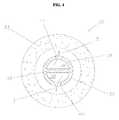
- FIG. 4illustrates a cross-section of the catalytic auto thermal reforming wand of FIG. 3 .
- FIG. 5illustrates a schematic flow diagram of a fuel cell utilizing the present invention.
- MCFC stacksare formed of a plurality of individual fuel cell sub-assemblies stacked together to provide a series DC relationship.
- Each individual sub-assemblyincludes an anode electrode, a cathode electrode, and an electrolyte held within a porous ceramic sheet known as an electrolyte matrix.
- bipolar separator platesuitable for use with the MCFC stack of the present invention, and is incorporated in its entirety herein by reference.
- Such a bipolar separator plateutilizes what is known in the art as an internal fuel manifold.
- a manifold chambertypically vertically oriented, is created by adjoining fuel manifolds for the purpose of distributing and collecting the reactant fuel.
- the ambient temperature of the fuel gas within the vertical chamberis quite high.
- the radiant heat of the interior walls of the manifold chamberheat the fuel gas.
- the opposite, or outer, side of the walls of the manifold chamberare constantly awash with and immersed in the exhausting oxidant gas that typically may exit the fuel cell stack at temperatures exceeding 650° C.
- the heat present within the exhausting oxidant gasis transferred to the incoming fuel gas within the manifold chamber.
- the manifold chamberacts as a heat exchanger between the oxidant gas and the fuel gas.
- the fuel feed stockmay achieve temperatures exceeding 500° C. within the confines of the manifold chamber prior to entry into the bipolar separator plates of the stack.
- FIG. 1shows the anode side of a bipolar separator plate 1 of a carbonate electrolyte fuel cell.
- the separator 1is equipped with a plurality of internal fuel inlet manifolds 2 A, 2 B, 2 C, . . . in fluid communication with an active area 3 of the separator 1 .
- Separator plate 1is further fitted with a plurality of internal fuel outlet manifolds 4 A, 4 B, 4 C, . . . , also in fluid communication with active area 3 of separator plate 1 .
- Fuel gas 5enters internal fuel inlet manifolds 2 A, 2 B, 2 C, . . . and accesses active area 3 to react in known fashion with an electrode (not shown) in active area 3 of an assembled fuel cell.
- the spent fuel gasexits separator plate 1 via the internal fuel outlet manifolds 4 A, 4 B, 4 C, . . . .
- Oxidant gas 6enters the fuel cell via an open edge of separator plate 1 , and accesses active area 3 on the opposing face of separator plate 1 . Spent oxidant gas exits separator plate 1 via opposing open edges of the separator plate. In the illustrated embodiment, the fuel gas 5 and oxidant gas 6 traverse separator plate 1 in a counter-flow or counter-current manner.
- Fuel cell stack 11includes a plurality of separator plates 1 A, 1 B, 1 C, . . . , electrodes 15 A, 15 B, 15 C, . . . , and electrolyte matrices 14 A, 14 B, 14 C, . . . .
- Each separator plate 1 A, 1 B, 1 C, . . .has an internal fuel inlet manifold 2 A, 2 B, 2 C, . . . .
- the fuel inlet manifolds 2 A, 2 B, 2 C, . . . of the fuel cells in the stackare aligned to form a manifold chamber 10 .
- the manifold chamberis generally substantially perpendicular to planes defined by the separator plates.
- Fuel gas 5enters manifold chamber 10 and accesses the plurality of separator plates 1 A, 1 B, 1 C, . . . .
- fuel gas 5is introduced to manifold chamber 10 at the ends of the fuel stack via piping or ducting (not shown).
- Oxidant gas 6exits the plurality of separator plates 1 A, 1 B, 1 C, . . . via the open edges of the separator plates.
- fuel gas 5 and oxidant gas 6are flowing counter-current to one another.
- a porous catalytic auto thermal reforming wand 30is positioned within manifold chamber.
- a wandrefers to a conduit, pipe, or tube-like member into which fuel gas and oxidant can flow.
- Wand 30is porous such that fuel gas 5 and oxidant 31 can pass through the wall of wand 30 .
- Wand 30is preferably a cylindrical tubular member.
- wand 30is formed of a non-conductive material.
- wand 30is formed of a ceramic, and most preferably is formed of ceramic alumina. It is to be appreciated that other shapes and materials for wand 30 are considered to be within the scope of the invention, and such shapes and materials will become readily apparent to those skilled in the art, given the benefit of this disclosure.
- Fuel gas 5 and oxidant 31may be introduced into wand 30 via piping or ducting, not shown, at the ends of the assembled fuel cell stack 11 . Fuel gas 5 and oxidant 31 are preferably uniformly distributed within the wand 30 via a mixing device 32 . Fuel gas 5 and oxidant 31 catalytically auto thermal reform on the interior surface, and within the pores of, wand 30 . The initiation of the catalytic auto thermal reforming process is aided by a catalyst 33 applied to the inside surface, and within the pores of, porous wand 30 .
- Catalyst 33may consist of any of the catalysts known in the art to affect the catalytic auto thermal reforming of the fuel gas and oxidant mixture, including, for example, platinum, palladium, nickel or ruthenium.
- the ratio of fuel gas 5 to oxidant 31is regulated to result in partial oxidation of the fuel, and to release sufficient heat so as to raise the ambient temperature of the internal manifold and wand 30 from about 500° C. to above that temperature required to achieve complete conversion of the fuel feed stock.
- the gassespermeate the porous wall of the catalytic auto thermal reforming wand 30 and further react with catalyst 33 to reform the remaining fuel in the gas.
- Wand 30is preferably removable from manifold chamber 10 for maintenance and replacement.
- the CATR wandis provided with the appropriate quantity of hydrocarbon-based fuel feed stock, steam, and oxidant to achieve sufficient combustion and resultant release of heat energy to complete the reformation of the fuel feed stock.
- the auto thermal reformation of the fueldoes consume a portion of the fuel and will, therefore, diminish the overall fuel efficiency of the fuel cell.
- the quantity of fuel needed to be combusted to elevate the temperature of the fuel feed stock from about 500° C. to above the temperature required to fully reform the fuel feed stockis considerably less than the amount of fuel gas which otherwise would be required to be combusted to elevate the temperature of the fuel feed stock from the ambient temperature that exists external to the fuel cell.
- An internal wand for an MCFC stackmay reform methane feed stock at temperatures known to result in near complete conversion of the methane.
- An internal wand for an MCFCmay further utilize other fuel stocks such as methanol. It is known that methanol will reform to hydrogen and carbon dioxide at temperatures less than that required to reform methane.
- methanolis delivered to the internal CATR wand of the MCFC stack, the quantity of oxidant required to combust the portion of fuel that results in the release of heat energy is reduced below that quantity required when methane is utilized as the fuel feed stock.
- the source of the oxidant for the CATRmay be derived from either the source of the cathode inlet oxidant or from the cathode outlet oxidant.
- An internal CATR wandwill not be subject to electrolyte contamination within the internal fuel inlet manifold when the combustion oxidant is sourced from the cathode inlet oxidant, since the gas stream has yet to accumulate electrolyte vapors.
- an internal CATR wandwill not be subject to electrolyte contamination within the internal fuel inlet manifold chamber when the combustion oxidant is sourced from the cathode outlet oxidant downstream from heat exchange with the cathode inlet oxidant.
- the oxidant inlet/outlet heat exchangeprecipitates entrained electrolyte vapors from the gas stream of the cathode outlet oxidant.
- the wandis not in contact with the bipolar separator plates or the electrodes or electrolyte matrices.
- FIG. 4A preferred embodiment of mixing device 32 is shown in FIG. 4 .
- Mixing device 32is formed of a cylindrical tube 34 having an internal wall 36 therein defining a first passage 38 and a second passage 39 .
- Fuel gas 5flows through first passage 38 and oxidant 31 flows through second passage 39 .
- a plurality of oxidant orifices 40are arranged axially along tube 34 to provide fluid communication between second passage 39 and the exterior of mixing device 32 .
- a plurality of fuel orifices 41are arranged axially along tube 34 to provide fluid communication between first passage 38 and the exterior of mixing device 32 .
- Fuel gas 5 and oxidant 31flow into first and second passages 38 , 39 , respectively, out through orifices 41 , 40 , respectively, and then through the pores of wand 30 , reacting with catalyst 33 .
- Orifices, 40 , 41promote uniform distribution and combustion of fuel gas 5 and oxidant 31 through wand 30 into manifold chamber 10 .
- Mixing device 32may have other constructions suitable for the delivery of fuel gas 5 and oxidant 31 .
- mixing device 32may be formed of two separate tubes having orifices formed therein.
- Mixing device 32may have any other suitable construction that provides for delivery of the fuel gas 5 and oxidant 31 throughout the length of the interior of the porous catalytic auto thermal reforming wand 30 . In this manner, thermal gradients within the wand will be minimized, thereby providing accurate control of the catalytic auto thermal reforming reaction prior to entry of the reformed fuel gas into the anode chambers of the fuel cell stack.
- fuel gas 5 and oxidant 31may be fed into passages 38 , 39 , respectively, co-currently from a first end of mixing device 32 , with mixing device 32 being capped at the opposing second end.
- mixing device 32may be fed with fuel gas 5 and oxidant 31 co-currently from both ends of mixing device 32 simultaneously.
- fuel gas 5may be fed into passage 38 at a first end of mixing device 32 , with the passage 38 being capped at the second end of mixing device 32 , while oxidant 31 is fed into passage 39 at the second end of mixing device 32 with passage 39 being capped at the first end of mixing device 32 , such that fuel gas 5 and oxidant 31 flow counter-currently.
- FIG. 5illustrates a schematic flow diagram for an MCFC system utilizing the catalyzed auto thermal reforming wand 30 within the manifold chamber 10 of a fuel cell stack 11 .
- Wand 30receives fuel gas 5 and oxidant 31 , with oxidant 31 being introduced via blower 55 .
- a CATR reaction within wand 30reforms the fuel gas 5 .
- the product of the CATR reactionis introduced to the anode, where it is oxidized to release electrons.
- Spent fuel 50is directed to a burner 51 , where it is combusted with air 52 .
- the product of the burner 51is introduced to the cathode, where it is reduced to receive electrons.
- the spent oxidant 53is directed to the heat exchanger 54 where heat is transferred to incoming air 52 , and entrained electrolyte vapor precipitates out of spent oxidant 55 .
- the oxidant 31 exiting heat exchanger 54is then introduced via blower 55 to manifold chamber 10 as described above.
- the source of oxidant 31may be air 52 .
Landscapes
- Life Sciences & Earth Sciences (AREA)
- Engineering & Computer Science (AREA)
- Manufacturing & Machinery (AREA)
- Sustainable Development (AREA)
- Sustainable Energy (AREA)
- Chemical & Material Sciences (AREA)
- Chemical Kinetics & Catalysis (AREA)
- Electrochemistry (AREA)
- General Chemical & Material Sciences (AREA)
- Fuel Cell (AREA)
Abstract
Description
Claims (22)
Priority Applications (1)
| Application Number | Priority Date | Filing Date | Title |
|---|---|---|---|
| US09/785,594US6602626B1 (en) | 2000-02-16 | 2001-02-16 | Fuel cell with internal thermally integrated autothermal reformer |
Applications Claiming Priority (2)
| Application Number | Priority Date | Filing Date | Title |
|---|---|---|---|
| US18282800P | 2000-02-16 | 2000-02-16 | |
| US09/785,594US6602626B1 (en) | 2000-02-16 | 2001-02-16 | Fuel cell with internal thermally integrated autothermal reformer |
Publications (1)
| Publication Number | Publication Date |
|---|---|
| US6602626B1true US6602626B1 (en) | 2003-08-05 |
Family
ID=27624901
Family Applications (1)
| Application Number | Title | Priority Date | Filing Date |
|---|---|---|---|
| US09/785,594Expired - Fee RelatedUS6602626B1 (en) | 2000-02-16 | 2001-02-16 | Fuel cell with internal thermally integrated autothermal reformer |
Country Status (1)
| Country | Link |
|---|---|
| US (1) | US6602626B1 (en) |
Cited By (10)
| Publication number | Priority date | Publication date | Assignee | Title |
|---|---|---|---|---|
| US20030203246A1 (en)* | 1997-07-16 | 2003-10-30 | Ronne Joel A. | Electrochemical fuel cell stack with improved reactant manifolding and sealing |
| US20050074648A1 (en)* | 2003-10-02 | 2005-04-07 | Arthur Alan R. | Integrated fuel cell stack and catalytic combustor apparatus, assembly, and method of use |
| WO2007129030A1 (en)* | 2006-05-05 | 2007-11-15 | Intelligent Energy Limited | Fuel cell fluid distribution plates |
| US20080076005A1 (en)* | 2006-09-22 | 2008-03-27 | Michel Bitton | Fuel cell fluid distribution system |
| US20100183930A1 (en)* | 2009-01-20 | 2010-07-22 | Adaptive Materials, Inc. | Method for controlling a water based fuel reformer |
| US20110189572A1 (en)* | 2009-01-30 | 2011-08-04 | Adaptive Materials, Inc. | Fuel cell system with flame protection member |
| US20110189578A1 (en)* | 2010-02-01 | 2011-08-04 | Adaptive Materials, Inc. | Fuel cell system including a resilient manifold interconnecting member |
| US8663851B2 (en) | 2007-04-17 | 2014-03-04 | Modine Manufacturing Company | Fuel cell system with partial external reforming and direct internal reforming |
| WO2014074107A1 (en) | 2012-11-09 | 2014-05-15 | United Technologies Corporation | Electrochemical device and method for controlling corrosion |
| US8796888B2 (en) | 2010-07-07 | 2014-08-05 | Adaptive Materials, Inc. | Wearable power management system |
Citations (84)
| Publication number | Priority date | Publication date | Assignee | Title |
|---|---|---|---|---|
| US3488226A (en) | 1965-11-08 | 1970-01-06 | Inst Gas Technology | Process for generation of hydrogen from hydrocarbons and use thereof in molten carbonate fuel cells |
| US4169917A (en) | 1978-07-10 | 1979-10-02 | Energy Research Corporation | Electrochemical cell and separator plate thereof |
| US4175165A (en) | 1977-07-20 | 1979-11-20 | Engelhard Minerals & Chemicals Corporation | Fuel cell system utilizing ion exchange membranes and bipolar plates |
| US4182795A (en) | 1978-07-10 | 1980-01-08 | Energy Research Corporation | Fuel cell thermal control and reforming of process gas hydrocarbons |
| US4200682A (en) | 1979-03-16 | 1980-04-29 | United Technologies Corporation | Integrated fuel cell and fuel conversion apparatus |
| US4365007A (en) | 1981-06-12 | 1982-12-21 | Energy Research Corporation | Fuel cell with internal reforming |
| US4476197A (en) | 1983-10-12 | 1984-10-09 | The United States Of America As Represented By The United States Department Of Energy | Integral manifolding structure for fuel cell core having parallel gas flow |
| US4510212A (en) | 1983-10-12 | 1985-04-09 | The United States Of America As Represented By The United States Department Of Energy | Solid oxide fuel cell having compound cross flow gas patterns |
| US4548876A (en) | 1984-10-17 | 1985-10-22 | The United States Of America As Represented By The United States Department Of Energy | Integrated current collector and catalyst support |
| JPS6124158A (en) | 1984-07-13 | 1986-02-01 | Mitsubishi Electric Corp | Molten carbonate fuel cell electrode |
| US4604331A (en) | 1984-05-29 | 1986-08-05 | The United States Of America As Represented By The United States Department Of Energy | Fuel cell separator plate with bellows-type sealing flanges |
| US4631239A (en) | 1985-12-04 | 1986-12-23 | Westinghouse Electric Corp. | Fuel cell plates with improved arrangement of process channels for enhanced pressure drop across the plates |
| US4702973A (en) | 1986-08-25 | 1987-10-27 | Institute Of Gas Technology | Dual compartment anode structure |
| US4753857A (en) | 1984-05-29 | 1988-06-28 | Ishikawajima-Harima Jukogyo Kabushiki Kaisha | Laminated fuel cell |
| US4781996A (en) | 1986-06-13 | 1988-11-01 | Hitachi, Ltd. | Fuel cell |
| US4853301A (en) | 1985-12-04 | 1989-08-01 | The United States Of America As Represented By The United States Department Of Energy | Fuel cell plates with skewed process channels for uniform distribution of stack compression load |
| US4857420A (en) | 1987-10-13 | 1989-08-15 | International Fuel Cell Corporation | Method of making monolithic solid oxide fuel cell stack |
| US4902586A (en) | 1989-08-28 | 1990-02-20 | International Fuel Cells Corporation | Once through molten carbonate fuel cell system |
| US4977041A (en) | 1987-05-08 | 1990-12-11 | Ishikawajima-Harima Heavy Industries Co., Ltd. | Fuel cell and method of ameliorating temperature distribution thereof |
| US4983472A (en) | 1989-11-24 | 1991-01-08 | International Fuel Cells Corporation | Fuel cell current collector |
| US5079105A (en) | 1989-05-18 | 1992-01-07 | Asea Brown Boveri Ltd. | Device for conversion of chemical energy from hydrocarbons into electric energy by an electrochemical high-temperature process |
| US5084364A (en) | 1989-07-12 | 1992-01-28 | Stichting Energieonderzoek Centrum Nederland (Ecn) | Separator plate for use in a gas fuel cell which comprises a set of electrodes, and also a stack of fuel cells |
| US5227256A (en) | 1989-05-03 | 1993-07-13 | Institute Of Gas Technology | Fully internal manifolded fuel cell stack |
| DE4206490A1 (en) | 1992-03-02 | 1993-09-09 | Fraunhofer Ges Forschung | Electrically conductive gas distributor structure for fuel cell - is texture roughened before application of hydrophobic coating |
| US5298342A (en) | 1992-10-20 | 1994-03-29 | M-C Power Corporation | Fuel cell crossover arrestor and pressure seal |
| US5362578A (en) | 1992-12-08 | 1994-11-08 | Institute Of Gas Technology | Integrated main rail, feed rail, and current collector |
| US5366819A (en) | 1993-10-06 | 1994-11-22 | Ceramatec, Inc. | Thermally integrated reformer for solid oxide fuel cells |
| US5399442A (en)* | 1993-02-08 | 1995-03-21 | Fuji Electric Co., Ltd. | Solid electrolyte fuel cell |
| US5424144A (en) | 1993-10-21 | 1995-06-13 | M-C Power Corporation | One piece separator plate with insert ring step design |
| US5458857A (en) | 1992-12-02 | 1995-10-17 | Rolls-Royce, Plc | Combined reformer and shift reactor |
| US5460897A (en) | 1994-03-18 | 1995-10-24 | Allied Signal Inc. | Solid oxide fuel cell stacking assembly |
| US5482792A (en) | 1993-04-30 | 1996-01-09 | De Nora Permelec S.P.A. | Electrochemical cell provided with ion exchange membranes and bipolar metal plates |
| US5527634A (en)* | 1992-02-20 | 1996-06-18 | Electric Power Research Institute, Inc. | Multiple manifold fuel cell |
| US5527363A (en) | 1993-12-10 | 1996-06-18 | Ballard Power Systems Inc. | Method of fabricating an embossed fluid flow field plate |
| US5543240A (en)* | 1994-08-17 | 1996-08-06 | Samsung Electronics Co., Ltd. | Fuel cell stack |
| US5558955A (en) | 1994-10-07 | 1996-09-24 | International Fuel Cells Corporation | Cathode reactant flow field component for a fuel cell stack |
| US5616431A (en)* | 1994-01-27 | 1997-04-01 | Mitsubishi Denki Kabushiki Kaisha | Fuel cell and its bipolar plate |
| US5707755A (en) | 1996-12-09 | 1998-01-13 | General Motors Corporation | PEM/SPE fuel cell |
| US5726105A (en) | 1995-04-20 | 1998-03-10 | International Fuel Cells | Composite article |
| US5733682A (en) | 1994-03-28 | 1998-03-31 | Forschungszentrum Julich Gmbh | Metallic bipolar plate for high-temperature fuel cells and method of making same |
| WO1998021773A1 (en) | 1996-11-14 | 1998-05-22 | Dais Corporation | Fuel cell stack assembly |
| US5770327A (en) | 1997-08-15 | 1998-06-23 | Northwestern University | Solid oxide fuel cell stack |
| US5773160A (en) | 1994-06-24 | 1998-06-30 | Ballard Power Systems Inc. | Electrochemical fuel cell stack with concurrent flow of coolant and oxidant streams and countercurrent flow of fuel and oxidant streams |
| US5773161A (en) | 1996-10-02 | 1998-06-30 | Energy Research Corporation | Bipolar separator |
| US5776624A (en) | 1996-12-23 | 1998-07-07 | General Motors Corporation | Brazed bipolar plates for PEM fuel cells |
| US5795665A (en) | 1996-08-19 | 1998-08-18 | Energy Research Corporation | Fuel cell sub-assembly with a plurality of dimples |
| US5798188A (en) | 1997-06-25 | 1998-08-25 | E. I. Dupont De Nemours And Company | Polymer electrolyte membrane fuel cell with bipolar plate having molded polymer projections |
| US5798187A (en) | 1996-09-27 | 1998-08-25 | The Regents Of The University Of California | Fuel cell with metal screen flow-field |
| US5811202A (en) | 1997-08-05 | 1998-09-22 | M-C Power Corporation | Hybrid molten carbonate fuel cell with unique sealing |
| US5833822A (en) | 1994-03-21 | 1998-11-10 | Ztek Corporation | Electrochemical converter having optimal pressure distribution |
| US5846668A (en) | 1996-03-07 | 1998-12-08 | Tanaka Kikinzoku Kogyo K. K. | Fuel cell, electrolytic cell and process of cooling and/or dehumidifying same |
| US5922485A (en) | 1996-10-22 | 1999-07-13 | Fuji Electric Co., Ltd. | Solid polymer electrolyte fuel cell |
| US5942349A (en) | 1995-03-15 | 1999-08-24 | Ceramic Fuel Cells Limited | Fuel cell interconnect device |
| US5993619A (en) | 1997-07-15 | 1999-11-30 | Niagara Mohawk Power Corporation | Electrochemical autothermal reformer |
| US5997594A (en) | 1996-10-30 | 1999-12-07 | Northwest Power Systems, Llc | Steam reformer with internal hydrogen purification |
| US6017648A (en)* | 1997-04-15 | 2000-01-25 | Plug Power, L.L.C. | Insertable fluid flow passage bridgepiece and method |
| US6025403A (en)* | 1997-07-07 | 2000-02-15 | Mobil Oil Corporation | Process for heat integration of an autothermal reformer and cogeneration power plant |
| US6033794A (en) | 1997-12-10 | 2000-03-07 | The United States Of America As Represented By The United States Department Of Energy | Multi-stage fuel cell system method and apparatus |
| US6037073A (en) | 1996-10-15 | 2000-03-14 | Lockheed Martin Energy Research Corporation | Bipolar plate/diffuser for a proton exchange membrane fuel cell |
| US6040075A (en) | 1994-12-17 | 2000-03-21 | Loughborough University Of Technology | Electrolytic and fuel cell arrangements |
| US6040076A (en) | 1998-03-03 | 2000-03-21 | M-C Power Corporation | One piece fuel cell separator plate |
| US6040073A (en) | 1996-08-07 | 2000-03-21 | Honda Giken Kogyo Kabushiki Kaisha | Fuel cell |
| US6045934A (en) | 1997-03-05 | 2000-04-04 | Fuji Electric Co., Ltd. | Solid polymer electrolyte fuel cell |
| US6045935A (en) | 1998-02-27 | 2000-04-04 | Corning Incorporated | Flexible inorganic electrolyte fuel cell design |
| US6048636A (en) | 1995-12-20 | 2000-04-11 | Kernforschungszentrum Julich GmbH | Electrode substrate for fuel cell |
| US6048633A (en) | 1998-03-02 | 2000-04-11 | Honda Giken Kogyo Kabushiki Kaisha | Fuel cell stack |
| US6048634A (en) | 1997-06-18 | 2000-04-11 | H Power Corporation | Fuel cell using water-soluble fuel |
| US6050331A (en) | 1994-05-20 | 2000-04-18 | International Fuel Cells L.L.C. | Coolant plate assembly for a fuel cell stack |
| US6051330A (en) | 1998-01-15 | 2000-04-18 | International Business Machines Corporation | Solid oxide fuel cell having vias and a composite interconnect |
| US6051331A (en)* | 1994-10-12 | 2000-04-18 | H Power Corporation | Fuel cell platelet separators having coordinate features |
| US6054228A (en) | 1996-06-06 | 2000-04-25 | Lynntech, Inc. | Fuel cell system for low pressure operation |
| US6054231A (en) | 1998-07-24 | 2000-04-25 | Gas Research Institute | Solid oxide fuel cell interconnector |
| US6071635A (en) | 1998-04-03 | 2000-06-06 | Plug Power, L.L.C. | Easily-formable fuel cell assembly fluid flow plate having conductivity and increased non-conductive material |
| US6071636A (en) | 1997-06-10 | 2000-06-06 | Automobiles Peugeot | Fuel cell of the type with plate-shaped reagents distributors |
| US6074692A (en) | 1998-04-10 | 2000-06-13 | General Motors Corporation | Method of making MEA for PEM/SPE fuel cell |
| US6080502A (en) | 1996-01-23 | 2000-06-27 | Siemens Aktengesellschaft | Fluid-cooled fuel cell with distribution ducts |
| US6096450A (en) | 1998-02-11 | 2000-08-01 | Plug Power Inc. | Fuel cell assembly fluid flow plate having conductive fibers and rigidizing material therein |
| US6099984A (en) | 1997-12-15 | 2000-08-08 | General Motors Corporation | Mirrored serpentine flow channels for fuel cell |
| US6103415A (en) | 1997-06-30 | 2000-08-15 | Aisin Seki Kabushiki Kaisha | Fuel cell with rectifying plates for uniform gas flow |
| US6117580A (en) | 1997-08-19 | 2000-09-12 | Daimlerchrysler Ag | Current collector for a fuel cell and method of making the same |
| US6124053A (en)* | 1998-07-09 | 2000-09-26 | Fuel Cell Technologies, Inc. | Fuel cell with internal combustion chamber |
| US6291089B1 (en)* | 1999-10-26 | 2001-09-18 | Alliedsignal Inc. | Radial planar fuel cell stack construction for solid electrolytes |
| US6361892B1 (en)* | 1999-12-06 | 2002-03-26 | Technology Management, Inc. | Electrochemical apparatus with reactant micro-channels |
| US6444339B1 (en)* | 2000-07-24 | 2002-09-03 | Microcell Corporation | Microcell electrochemical device assemblies with thermal management subsystem, and method of making and using the same |
- 2001
- 2001-02-16USUS09/785,594patent/US6602626B1/ennot_activeExpired - Fee Related
Patent Citations (86)
| Publication number | Priority date | Publication date | Assignee | Title |
|---|---|---|---|---|
| US3488226A (en) | 1965-11-08 | 1970-01-06 | Inst Gas Technology | Process for generation of hydrogen from hydrocarbons and use thereof in molten carbonate fuel cells |
| US4175165A (en) | 1977-07-20 | 1979-11-20 | Engelhard Minerals & Chemicals Corporation | Fuel cell system utilizing ion exchange membranes and bipolar plates |
| US4169917A (en) | 1978-07-10 | 1979-10-02 | Energy Research Corporation | Electrochemical cell and separator plate thereof |
| US4182795A (en) | 1978-07-10 | 1980-01-08 | Energy Research Corporation | Fuel cell thermal control and reforming of process gas hydrocarbons |
| US4200682A (en) | 1979-03-16 | 1980-04-29 | United Technologies Corporation | Integrated fuel cell and fuel conversion apparatus |
| US4365007A (en) | 1981-06-12 | 1982-12-21 | Energy Research Corporation | Fuel cell with internal reforming |
| US4476197A (en) | 1983-10-12 | 1984-10-09 | The United States Of America As Represented By The United States Department Of Energy | Integral manifolding structure for fuel cell core having parallel gas flow |
| US4510212A (en) | 1983-10-12 | 1985-04-09 | The United States Of America As Represented By The United States Department Of Energy | Solid oxide fuel cell having compound cross flow gas patterns |
| US4753857A (en) | 1984-05-29 | 1988-06-28 | Ishikawajima-Harima Jukogyo Kabushiki Kaisha | Laminated fuel cell |
| US4604331A (en) | 1984-05-29 | 1986-08-05 | The United States Of America As Represented By The United States Department Of Energy | Fuel cell separator plate with bellows-type sealing flanges |
| JPS6124158A (en) | 1984-07-13 | 1986-02-01 | Mitsubishi Electric Corp | Molten carbonate fuel cell electrode |
| US4548876A (en) | 1984-10-17 | 1985-10-22 | The United States Of America As Represented By The United States Department Of Energy | Integrated current collector and catalyst support |
| US4631239A (en) | 1985-12-04 | 1986-12-23 | Westinghouse Electric Corp. | Fuel cell plates with improved arrangement of process channels for enhanced pressure drop across the plates |
| US4853301A (en) | 1985-12-04 | 1989-08-01 | The United States Of America As Represented By The United States Department Of Energy | Fuel cell plates with skewed process channels for uniform distribution of stack compression load |
| US4781996A (en) | 1986-06-13 | 1988-11-01 | Hitachi, Ltd. | Fuel cell |
| US4702973A (en) | 1986-08-25 | 1987-10-27 | Institute Of Gas Technology | Dual compartment anode structure |
| US4977041A (en) | 1987-05-08 | 1990-12-11 | Ishikawajima-Harima Heavy Industries Co., Ltd. | Fuel cell and method of ameliorating temperature distribution thereof |
| US4978589A (en) | 1987-05-08 | 1990-12-18 | Ishikawajima-Harima Heavy Industries Co., Ltd. | Fuel cell |
| US4857420A (en) | 1987-10-13 | 1989-08-15 | International Fuel Cell Corporation | Method of making monolithic solid oxide fuel cell stack |
| US5227256A (en) | 1989-05-03 | 1993-07-13 | Institute Of Gas Technology | Fully internal manifolded fuel cell stack |
| US5079105A (en) | 1989-05-18 | 1992-01-07 | Asea Brown Boveri Ltd. | Device for conversion of chemical energy from hydrocarbons into electric energy by an electrochemical high-temperature process |
| US5084364A (en) | 1989-07-12 | 1992-01-28 | Stichting Energieonderzoek Centrum Nederland (Ecn) | Separator plate for use in a gas fuel cell which comprises a set of electrodes, and also a stack of fuel cells |
| US4902586A (en) | 1989-08-28 | 1990-02-20 | International Fuel Cells Corporation | Once through molten carbonate fuel cell system |
| US4983472A (en) | 1989-11-24 | 1991-01-08 | International Fuel Cells Corporation | Fuel cell current collector |
| US5527634A (en)* | 1992-02-20 | 1996-06-18 | Electric Power Research Institute, Inc. | Multiple manifold fuel cell |
| DE4206490A1 (en) | 1992-03-02 | 1993-09-09 | Fraunhofer Ges Forschung | Electrically conductive gas distributor structure for fuel cell - is texture roughened before application of hydrophobic coating |
| US5298342A (en) | 1992-10-20 | 1994-03-29 | M-C Power Corporation | Fuel cell crossover arrestor and pressure seal |
| US5458857A (en) | 1992-12-02 | 1995-10-17 | Rolls-Royce, Plc | Combined reformer and shift reactor |
| US5362578A (en) | 1992-12-08 | 1994-11-08 | Institute Of Gas Technology | Integrated main rail, feed rail, and current collector |
| US5503945A (en) | 1992-12-08 | 1996-04-02 | Institute Of Gas Technology | Separator plate for a fuel cell |
| US5399442A (en)* | 1993-02-08 | 1995-03-21 | Fuji Electric Co., Ltd. | Solid electrolyte fuel cell |
| US5482792A (en) | 1993-04-30 | 1996-01-09 | De Nora Permelec S.P.A. | Electrochemical cell provided with ion exchange membranes and bipolar metal plates |
| US5366819A (en) | 1993-10-06 | 1994-11-22 | Ceramatec, Inc. | Thermally integrated reformer for solid oxide fuel cells |
| US5424144A (en) | 1993-10-21 | 1995-06-13 | M-C Power Corporation | One piece separator plate with insert ring step design |
| US5527363A (en) | 1993-12-10 | 1996-06-18 | Ballard Power Systems Inc. | Method of fabricating an embossed fluid flow field plate |
| US5616431A (en)* | 1994-01-27 | 1997-04-01 | Mitsubishi Denki Kabushiki Kaisha | Fuel cell and its bipolar plate |
| US5460897A (en) | 1994-03-18 | 1995-10-24 | Allied Signal Inc. | Solid oxide fuel cell stacking assembly |
| US5833822A (en) | 1994-03-21 | 1998-11-10 | Ztek Corporation | Electrochemical converter having optimal pressure distribution |
| US5733682A (en) | 1994-03-28 | 1998-03-31 | Forschungszentrum Julich Gmbh | Metallic bipolar plate for high-temperature fuel cells and method of making same |
| US6050331A (en) | 1994-05-20 | 2000-04-18 | International Fuel Cells L.L.C. | Coolant plate assembly for a fuel cell stack |
| US5773160A (en) | 1994-06-24 | 1998-06-30 | Ballard Power Systems Inc. | Electrochemical fuel cell stack with concurrent flow of coolant and oxidant streams and countercurrent flow of fuel and oxidant streams |
| US5543240A (en)* | 1994-08-17 | 1996-08-06 | Samsung Electronics Co., Ltd. | Fuel cell stack |
| US5558955A (en) | 1994-10-07 | 1996-09-24 | International Fuel Cells Corporation | Cathode reactant flow field component for a fuel cell stack |
| US6051331A (en)* | 1994-10-12 | 2000-04-18 | H Power Corporation | Fuel cell platelet separators having coordinate features |
| US6040075A (en) | 1994-12-17 | 2000-03-21 | Loughborough University Of Technology | Electrolytic and fuel cell arrangements |
| US5942349A (en) | 1995-03-15 | 1999-08-24 | Ceramic Fuel Cells Limited | Fuel cell interconnect device |
| US5726105A (en) | 1995-04-20 | 1998-03-10 | International Fuel Cells | Composite article |
| US6048636A (en) | 1995-12-20 | 2000-04-11 | Kernforschungszentrum Julich GmbH | Electrode substrate for fuel cell |
| US6080502A (en) | 1996-01-23 | 2000-06-27 | Siemens Aktengesellschaft | Fluid-cooled fuel cell with distribution ducts |
| US5846668A (en) | 1996-03-07 | 1998-12-08 | Tanaka Kikinzoku Kogyo K. K. | Fuel cell, electrolytic cell and process of cooling and/or dehumidifying same |
| US6054228A (en) | 1996-06-06 | 2000-04-25 | Lynntech, Inc. | Fuel cell system for low pressure operation |
| US6040073A (en) | 1996-08-07 | 2000-03-21 | Honda Giken Kogyo Kabushiki Kaisha | Fuel cell |
| US5795665A (en) | 1996-08-19 | 1998-08-18 | Energy Research Corporation | Fuel cell sub-assembly with a plurality of dimples |
| US5798187A (en) | 1996-09-27 | 1998-08-25 | The Regents Of The University Of California | Fuel cell with metal screen flow-field |
| US5773161A (en) | 1996-10-02 | 1998-06-30 | Energy Research Corporation | Bipolar separator |
| US6037073A (en) | 1996-10-15 | 2000-03-14 | Lockheed Martin Energy Research Corporation | Bipolar plate/diffuser for a proton exchange membrane fuel cell |
| US5922485A (en) | 1996-10-22 | 1999-07-13 | Fuji Electric Co., Ltd. | Solid polymer electrolyte fuel cell |
| US5997594A (en) | 1996-10-30 | 1999-12-07 | Northwest Power Systems, Llc | Steam reformer with internal hydrogen purification |
| WO1998021773A1 (en) | 1996-11-14 | 1998-05-22 | Dais Corporation | Fuel cell stack assembly |
| US5707755A (en) | 1996-12-09 | 1998-01-13 | General Motors Corporation | PEM/SPE fuel cell |
| US5776624A (en) | 1996-12-23 | 1998-07-07 | General Motors Corporation | Brazed bipolar plates for PEM fuel cells |
| US6045934A (en) | 1997-03-05 | 2000-04-04 | Fuji Electric Co., Ltd. | Solid polymer electrolyte fuel cell |
| US6017648A (en)* | 1997-04-15 | 2000-01-25 | Plug Power, L.L.C. | Insertable fluid flow passage bridgepiece and method |
| US6071636A (en) | 1997-06-10 | 2000-06-06 | Automobiles Peugeot | Fuel cell of the type with plate-shaped reagents distributors |
| US6048634A (en) | 1997-06-18 | 2000-04-11 | H Power Corporation | Fuel cell using water-soluble fuel |
| US5798188A (en) | 1997-06-25 | 1998-08-25 | E. I. Dupont De Nemours And Company | Polymer electrolyte membrane fuel cell with bipolar plate having molded polymer projections |
| US6103415A (en) | 1997-06-30 | 2000-08-15 | Aisin Seki Kabushiki Kaisha | Fuel cell with rectifying plates for uniform gas flow |
| US6025403A (en)* | 1997-07-07 | 2000-02-15 | Mobil Oil Corporation | Process for heat integration of an autothermal reformer and cogeneration power plant |
| US5993619A (en) | 1997-07-15 | 1999-11-30 | Niagara Mohawk Power Corporation | Electrochemical autothermal reformer |
| US5811202A (en) | 1997-08-05 | 1998-09-22 | M-C Power Corporation | Hybrid molten carbonate fuel cell with unique sealing |
| US5770327A (en) | 1997-08-15 | 1998-06-23 | Northwestern University | Solid oxide fuel cell stack |
| US6117580A (en) | 1997-08-19 | 2000-09-12 | Daimlerchrysler Ag | Current collector for a fuel cell and method of making the same |
| US6033794A (en) | 1997-12-10 | 2000-03-07 | The United States Of America As Represented By The United States Department Of Energy | Multi-stage fuel cell system method and apparatus |
| US6099984A (en) | 1997-12-15 | 2000-08-08 | General Motors Corporation | Mirrored serpentine flow channels for fuel cell |
| US6051330A (en) | 1998-01-15 | 2000-04-18 | International Business Machines Corporation | Solid oxide fuel cell having vias and a composite interconnect |
| US6096450A (en) | 1998-02-11 | 2000-08-01 | Plug Power Inc. | Fuel cell assembly fluid flow plate having conductive fibers and rigidizing material therein |
| US6045935A (en) | 1998-02-27 | 2000-04-04 | Corning Incorporated | Flexible inorganic electrolyte fuel cell design |
| US6048633A (en) | 1998-03-02 | 2000-04-11 | Honda Giken Kogyo Kabushiki Kaisha | Fuel cell stack |
| US6040076A (en) | 1998-03-03 | 2000-03-21 | M-C Power Corporation | One piece fuel cell separator plate |
| US6071635A (en) | 1998-04-03 | 2000-06-06 | Plug Power, L.L.C. | Easily-formable fuel cell assembly fluid flow plate having conductivity and increased non-conductive material |
| US6074692A (en) | 1998-04-10 | 2000-06-13 | General Motors Corporation | Method of making MEA for PEM/SPE fuel cell |
| US6124053A (en)* | 1998-07-09 | 2000-09-26 | Fuel Cell Technologies, Inc. | Fuel cell with internal combustion chamber |
| US6054231A (en) | 1998-07-24 | 2000-04-25 | Gas Research Institute | Solid oxide fuel cell interconnector |
| US6291089B1 (en)* | 1999-10-26 | 2001-09-18 | Alliedsignal Inc. | Radial planar fuel cell stack construction for solid electrolytes |
| US6361892B1 (en)* | 1999-12-06 | 2002-03-26 | Technology Management, Inc. | Electrochemical apparatus with reactant micro-channels |
| US6444339B1 (en)* | 2000-07-24 | 2002-09-03 | Microcell Corporation | Microcell electrochemical device assemblies with thermal management subsystem, and method of making and using the same |
Non-Patent Citations (1)
| Title |
|---|
| Toshihiko, "Flat Solid Electrolyte Fuel Cell," abstract of patent No. 07022038, Patent Abstracts of Japan (1995). |
Cited By (25)
| Publication number | Priority date | Publication date | Assignee | Title |
|---|---|---|---|---|
| US6764783B2 (en)* | 1997-07-16 | 2004-07-20 | Ballard Power Systems Inc. | Electrochemical fuel cell stack with improved reactant manifolding and sealing |
| US20030203246A1 (en)* | 1997-07-16 | 2003-10-30 | Ronne Joel A. | Electrochemical fuel cell stack with improved reactant manifolding and sealing |
| WO2005034269A1 (en)* | 2003-10-01 | 2005-04-14 | Hewlett-Packard Development Company L.P. | Integrated fuel cell stack and catalytic combustor apparatus, assembly, and method of use |
| US20080085434A1 (en)* | 2003-10-02 | 2008-04-10 | Arthur Alan R | Integrated fuel cell stack and catalytic combustor apparatus, assembly, and method of use |
| US20050074648A1 (en)* | 2003-10-02 | 2005-04-07 | Arthur Alan R. | Integrated fuel cell stack and catalytic combustor apparatus, assembly, and method of use |
| US8062803B2 (en) | 2003-10-02 | 2011-11-22 | Eveready Battery Company, Inc. | Fuel cell system and a method of generating electricity |
| US7306868B2 (en) | 2003-10-02 | 2007-12-11 | Hewlett-Packard Development Company, L.P. | Integrated fuel cell stack and catalytic combustor apparatus, assembly, and method of use |
| WO2007129030A1 (en)* | 2006-05-05 | 2007-11-15 | Intelligent Energy Limited | Fuel cell fluid distribution plates |
| US20090325037A1 (en)* | 2006-05-05 | 2009-12-31 | Intelligent Energy Limited | Fuel cell fluid distribution plates |
| CN101438441B (en)* | 2006-05-05 | 2011-02-02 | 智慧能量有限公司 | Fuel cell fluid distribution plates |
| US8017279B2 (en) | 2006-05-05 | 2011-09-13 | Intelligent Energy Limited | Fuel cell fluid distribution plates |
| TWI411155B (en)* | 2006-05-05 | 2013-10-01 | Intelligent Energy Ltd | Fuel cell fluid distribution plates |
| US20080076005A1 (en)* | 2006-09-22 | 2008-03-27 | Michel Bitton | Fuel cell fluid distribution system |
| US8663851B2 (en) | 2007-04-17 | 2014-03-04 | Modine Manufacturing Company | Fuel cell system with partial external reforming and direct internal reforming |
| US20100183930A1 (en)* | 2009-01-20 | 2010-07-22 | Adaptive Materials, Inc. | Method for controlling a water based fuel reformer |
| US8409760B2 (en)* | 2009-01-20 | 2013-04-02 | Adaptive Materials, Inc. | Method for controlling a water based fuel reformer |
| US20110189572A1 (en)* | 2009-01-30 | 2011-08-04 | Adaptive Materials, Inc. | Fuel cell system with flame protection member |
| US8936888B2 (en) | 2009-01-30 | 2015-01-20 | Adaptive Materials, Inc. | Fuel cell system with flame protection member |
| US20110189578A1 (en)* | 2010-02-01 | 2011-08-04 | Adaptive Materials, Inc. | Fuel cell system including a resilient manifold interconnecting member |
| US8796888B2 (en) | 2010-07-07 | 2014-08-05 | Adaptive Materials, Inc. | Wearable power management system |
| WO2014074107A1 (en) | 2012-11-09 | 2014-05-15 | United Technologies Corporation | Electrochemical device and method for controlling corrosion |
| CN104769748A (en)* | 2012-11-09 | 2015-07-08 | 联合工艺公司 | Electrochemical device and method for controlling corrosion |
| US20150288011A1 (en)* | 2012-11-09 | 2015-10-08 | United Technologies Corporation | Electrochemical device and method for controlling corrosion |
| CN104769748B (en)* | 2012-11-09 | 2017-11-07 | 联合工艺公司 | Electrochemical appliance and method for control corrosion rate |
| US10177389B2 (en)* | 2012-11-09 | 2019-01-08 | United Technologies Corporation | Electrochemical device and method for controlling corrosion |
Similar Documents
| Publication | Publication Date | Title |
|---|---|---|
| JP4340315B2 (en) | FUEL CELL POWER PLANT AND METHOD OF OPERATING FUEL CELL POWER PLANT | |
| US9105894B2 (en) | Fuel cell system containing anode tail gas oxidizer and hybrid heat exchanger/reformer | |
| KR100750794B1 (en) | Molten Carbonate Fuel Cell with Indirect Internal Reformer | |
| EP0076019B1 (en) | A fuel cell generator and method of operating same | |
| JP2919588B2 (en) | Electrochemical battery | |
| CN100367556C (en) | Thermally enhanced small reformer | |
| US8920997B2 (en) | Hybrid fuel heat exchanger—pre-reformer in SOFC systems | |
| US20050089731A1 (en) | Solid oxide fuel cell system | |
| EP0242200A1 (en) | Fuel cell generators | |
| US7338727B2 (en) | Method of operating a fuel cell to provide a heated and humidified oxidant | |
| CN1436378A (en) | Catalytic humidifier and heater, primarily for humidification of oxidant stream for fuel cell | |
| US8486162B2 (en) | Reformer for fuel cell system and fuel cell system having the same | |
| US6514634B1 (en) | Method and system for humidification of a fuel | |
| US6602626B1 (en) | Fuel cell with internal thermally integrated autothermal reformer | |
| US8318363B2 (en) | Reformer for fuel cell system and fuel cell system comprising the same | |
| US7524572B2 (en) | Fuel cell system with thermally integrated combustor and corrugated foil reformer | |
| JP4956946B2 (en) | Fuel cell | |
| JP2007200709A (en) | Solid oxide fuel cell stack and method for operating the same | |
| US20060046118A1 (en) | Fuel cell stack having improved cooling structure | |
| JP4696495B2 (en) | Fuel cell power generator | |
| JP6522393B2 (en) | Fuel cell device and fuel cell system | |
| US20080023322A1 (en) | Fuel processor | |
| JP2001253703A (en) | Fuel reformer | |
| KR100560442B1 (en) | Fuel cell system | |
| JP2016213085A (en) | Solid oxide type fuel battery system |
Legal Events
| Date | Code | Title | Description |
|---|---|---|---|
| AS | Assignment | Owner name:GENCELL CORPORATION, CONNECTICUT Free format text:ASSIGNMENT OF ASSIGNORS INTEREST;ASSIGNOR:ALLEN, JEFFREY P.;REEL/FRAME:013745/0779 Effective date:20021231 | |
| AS | Assignment | Owner name:CONNECTICUT INNOVATIONS, INCORPORATED, CONNECTICUT Free format text:ASSIGNMENT OF ASSIGNORS INTEREST;ASSIGNOR:GENCELL CORPORATION;REEL/FRAME:017555/0925 Effective date:20060502 | |
| REFU | Refund | Free format text:REFUND - PAYMENT OF MAINTENANCE FEE, 4TH YEAR, LARGE ENTITY (ORIGINAL EVENT CODE: R1551); ENTITY STATUS OF PATENT OWNER: LARGE ENTITY | |
| FPAY | Fee payment | Year of fee payment:4 | |
| SULP | Surcharge for late payment | ||
| AS | Assignment | Owner name:NANODYNAMICS ENERGY, INC., NEW YORK Free format text:SECURITY AGREEMENT;ASSIGNOR:GENCELL CORPORATION;REEL/FRAME:018898/0261 Effective date:20070129 | |
| REMI | Maintenance fee reminder mailed | ||
| AS | Assignment | Owner name:AGNI GENCELL INC., CONNECTICUT Free format text:MERGER;ASSIGNOR:GENCELL CORPORATION;REEL/FRAME:022320/0972 Effective date:20081006 | |
| REMI | Maintenance fee reminder mailed | ||
| LAPS | Lapse for failure to pay maintenance fees | ||
| STCH | Information on status: patent discontinuation | Free format text:PATENT EXPIRED DUE TO NONPAYMENT OF MAINTENANCE FEES UNDER 37 CFR 1.362 | |
| FP | Lapsed due to failure to pay maintenance fee | Effective date:20110805 |