US6602325B1 - Fluid separation assembly - Google Patents
Fluid separation assemblyDownload PDFInfo
- Publication number
- US6602325B1 US6602325B1US09/422,505US42250599AUS6602325B1US 6602325 B1US6602325 B1US 6602325B1US 42250599 AUS42250599 AUS 42250599AUS 6602325 B1US6602325 B1US 6602325B1
- Authority
- US
- United States
- Prior art keywords
- fluid
- membrane
- separation assembly
- wire mesh
- fluid separation
- Prior art date
- Legal status (The legal status is an assumption and is not a legal conclusion. Google has not performed a legal analysis and makes no representation as to the accuracy of the status listed.)
- Expired - Lifetime
Links
- 239000012530fluidSubstances0.000titleclaimsabstractdescription135
- 238000000926separation methodMethods0.000titleclaimsabstractdescription87
- 239000012528membraneSubstances0.000claimsabstractdescription204
- 239000001257hydrogenSubstances0.000claimsabstractdescription34
- 229910052739hydrogenInorganic materials0.000claimsabstractdescription34
- UFHFLCQGNIYNRP-UHFFFAOYSA-NHydrogenChemical compound[H][H]UFHFLCQGNIYNRP-UHFFFAOYSA-N0.000claimsabstractdescription30
- 239000000203mixtureSubstances0.000claimsabstractdescription30
- 238000009792diffusion processMethods0.000claimsabstractdescription23
- 238000000429assemblyMethods0.000claimsabstractdescription19
- 230000000712assemblyEffects0.000claimsabstractdescription19
- 230000004888barrier functionEffects0.000claimsabstractdescription17
- 239000010409thin filmSubstances0.000claimsabstractdescription10
- 150000004767nitridesChemical class0.000claimsabstractdescription8
- 229910000951AluminideInorganic materials0.000claimsabstractdescription7
- 229910021332silicideInorganic materials0.000claimsabstractdescription6
- 239000012466permeateSubstances0.000claimsdescription50
- 238000000034methodMethods0.000claimsdescription16
- 239000011324beadSubstances0.000claimsdescription6
- KDLHZDBZIXYQEI-UHFFFAOYSA-NPalladiumChemical compound[Pd]KDLHZDBZIXYQEI-UHFFFAOYSA-N0.000claimsdescription4
- 150000001247metal acetylidesChemical class0.000claimsdescription4
- 229910001252Pd alloyInorganic materials0.000claimsdescription2
- 238000004519manufacturing processMethods0.000claimsdescription2
- 229910052763palladiumInorganic materials0.000claimsdescription2
- 150000001875compoundsChemical class0.000claims4
- 239000010935stainless steelSubstances0.000claims4
- 229910001220stainless steelInorganic materials0.000claims4
- 239000011248coating agentSubstances0.000claims3
- 238000000576coating methodMethods0.000claims3
- 206010010144Completed suicideDiseases0.000claims1
- 230000002093peripheral effectEffects0.000claims1
- 238000007789sealingMethods0.000claims1
- 239000007789gasSubstances0.000abstractdescription32
- FVBUAEGBCNSCDD-UHFFFAOYSA-Nsilicide(4-)Chemical compound[Si-4]FVBUAEGBCNSCDD-UHFFFAOYSA-N0.000abstractdescription2
- 239000000463materialSubstances0.000description16
- 239000000956alloySubstances0.000description15
- 229910045601alloyInorganic materials0.000description14
- PXHVJJICTQNCMI-UHFFFAOYSA-NNickelChemical compound[Ni]PXHVJJICTQNCMI-UHFFFAOYSA-N0.000description12
- 229910000934Monel 400Inorganic materials0.000description8
- OANFWJQPUHQWDL-UHFFFAOYSA-Ncopper iron manganese nickelChemical compound[Mn].[Fe].[Ni].[Cu]OANFWJQPUHQWDL-UHFFFAOYSA-N0.000description8
- 238000003466weldingMethods0.000description8
- 229910000881Cu alloyInorganic materials0.000description7
- 229910000990Ni alloyInorganic materials0.000description7
- RYGMFSIKBFXOCR-UHFFFAOYSA-NCopperChemical compound[Cu]RYGMFSIKBFXOCR-UHFFFAOYSA-N0.000description6
- 239000010949copperSubstances0.000description6
- 229910052802copperInorganic materials0.000description6
- 229910052751metalInorganic materials0.000description6
- 239000002184metalSubstances0.000description6
- 229910052759nickelInorganic materials0.000description6
- 238000009826distributionMethods0.000description5
- 230000004927fusionEffects0.000description5
- 238000005516engineering processMethods0.000description4
- 150000002431hydrogenChemical class0.000description4
- 238000005240physical vapour depositionMethods0.000description4
- 238000005219brazingMethods0.000description2
- 238000010894electron beam technologyMethods0.000description2
- 239000004744fabricSubstances0.000description2
- 239000011261inert gasSubstances0.000description2
- 238000005304joiningMethods0.000description2
- 230000005012migrationEffects0.000description2
- 238000013508migrationMethods0.000description2
- 238000012986modificationMethods0.000description2
- 230000004048modificationEffects0.000description2
- 239000010970precious metalSubstances0.000description2
- 230000008569processEffects0.000description2
- 238000005476solderingMethods0.000description2
- 229910001256stainless steel alloyInorganic materials0.000description2
- WFKWXMTUELFFGS-UHFFFAOYSA-NtungstenChemical compound[W]WFKWXMTUELFFGS-UHFFFAOYSA-N0.000description2
- 229910052721tungstenInorganic materials0.000description2
- 239000010937tungstenSubstances0.000description2
- 229910000851Alloy steelInorganic materials0.000description1
- 229910000831SteelInorganic materials0.000description1
- 230000008859changeEffects0.000description1
- 238000005229chemical vapour depositionMethods0.000description1
- 239000002131composite materialSubstances0.000description1
- 230000008602contractionEffects0.000description1
- 238000007796conventional methodMethods0.000description1
- 238000011161developmentMethods0.000description1
- 230000000694effectsEffects0.000description1
- 239000010408filmSubstances0.000description1
- 125000004435hydrogen atomChemical group[H]*0.000description1
- 230000000737periodic effectEffects0.000description1
- 238000005546reactive sputteringMethods0.000description1
- 238000011160researchMethods0.000description1
- 230000000717retained effectEffects0.000description1
- 239000007787solidSubstances0.000description1
- 239000010959steelSubstances0.000description1
- 239000000126substanceSubstances0.000description1
- 229910052723transition metalInorganic materials0.000description1
- 150000003624transition metalsChemical class0.000description1
- 238000007740vapor depositionMethods0.000description1
Images


Classifications
- B—PERFORMING OPERATIONS; TRANSPORTING
- B01—PHYSICAL OR CHEMICAL PROCESSES OR APPARATUS IN GENERAL
- B01D—SEPARATION
- B01D53/00—Separation of gases or vapours; Recovering vapours of volatile solvents from gases; Chemical or biological purification of waste gases, e.g. engine exhaust gases, smoke, fumes, flue gases, aerosols
- B01D53/22—Separation of gases or vapours; Recovering vapours of volatile solvents from gases; Chemical or biological purification of waste gases, e.g. engine exhaust gases, smoke, fumes, flue gases, aerosols by diffusion
- B—PERFORMING OPERATIONS; TRANSPORTING
- B01—PHYSICAL OR CHEMICAL PROCESSES OR APPARATUS IN GENERAL
- B01D—SEPARATION
- B01D63/00—Apparatus in general for separation processes using semi-permeable membranes
- B01D63/08—Flat membrane modules
- B01D63/081—Manufacturing thereof
- B—PERFORMING OPERATIONS; TRANSPORTING
- B01—PHYSICAL OR CHEMICAL PROCESSES OR APPARATUS IN GENERAL
- B01D—SEPARATION
- B01D63/00—Apparatus in general for separation processes using semi-permeable membranes
- B01D63/08—Flat membrane modules
- B01D63/082—Flat membrane modules comprising a stack of flat membranes
- B01D63/084—Flat membrane modules comprising a stack of flat membranes at least one flow duct intersecting the membranes
- C—CHEMISTRY; METALLURGY
- C01—INORGANIC CHEMISTRY
- C01B—NON-METALLIC ELEMENTS; COMPOUNDS THEREOF; METALLOIDS OR COMPOUNDS THEREOF NOT COVERED BY SUBCLASS C01C
- C01B3/00—Hydrogen; Gaseous mixtures containing hydrogen; Separation of hydrogen from mixtures containing it; Purification of hydrogen
- C01B3/50—Separation of hydrogen or hydrogen containing gases from gaseous mixtures, e.g. purification
- C01B3/501—Separation of hydrogen or hydrogen containing gases from gaseous mixtures, e.g. purification by diffusion
- C01B3/503—Separation of hydrogen or hydrogen containing gases from gaseous mixtures, e.g. purification by diffusion characterised by the membrane
- B—PERFORMING OPERATIONS; TRANSPORTING
- B01—PHYSICAL OR CHEMICAL PROCESSES OR APPARATUS IN GENERAL
- B01D—SEPARATION
- B01D2313/00—Details relating to membrane modules or apparatus
- B01D2313/42—Catalysts within the flow path
- Y—GENERAL TAGGING OF NEW TECHNOLOGICAL DEVELOPMENTS; GENERAL TAGGING OF CROSS-SECTIONAL TECHNOLOGIES SPANNING OVER SEVERAL SECTIONS OF THE IPC; TECHNICAL SUBJECTS COVERED BY FORMER USPC CROSS-REFERENCE ART COLLECTIONS [XRACs] AND DIGESTS
- Y10—TECHNICAL SUBJECTS COVERED BY FORMER USPC
- Y10S—TECHNICAL SUBJECTS COVERED BY FORMER USPC CROSS-REFERENCE ART COLLECTIONS [XRACs] AND DIGESTS
- Y10S55/00—Gas separation
- Y10S55/05—Methods of making filter
Definitions
- the present inventionrelates to apparatuses and methods for separation of a desired fluid from a fluid mixture. More particularly, the present invention is generally directed to a fluid separation assembly having a membrane permeable to a desired fluid and a wire mesh membrane support that supports the permeable membrane and has a barrier that prevents intermetallic diffusion bonding.
- the gas mixturewhen separating a gas from a mixture of gases by diffusion, the gas mixture is typically brought into contact with a nonporous membrane which is selectively permeable to the gas that is desired to be separated from the gas mixture.
- the desired gasdiffuses through the permeable membrane and is separated from the other gas mixture.
- a pressure differential between opposite sides of the permeable membraneis usually created such that the diffusion process proceeds more effectively, wherein a higher partial pressure of the gas to be separated is maintained on the gas mixture side of the permeable membrane.
- the gas mixture and the selectively permeable membranecan be maintained at elevated temperatures to facilitate the separation of the desired gas from the gas mixture. This type of process can be used to separate hydrogen from a gas mixture containing hydrogen.
- the permeable membraneis permeable to hydrogen and is commonly constructed from palladium or a palladium alloy.
- the exposure to high temperatures and mechanical stresses created by the pressure differentialdictates that the permeable membrane be supported in such a way that does not obstruct passage of the desired gas through the membrane.
- One type of conventional apparatus used for the separation of hydrogen from a gas mixtureemploys a woven refractory-type cloth for supporting the permeable membrane during the separation process.
- the disadvantage of this type of conventional membrane supportis that the cloth support is susceptible to failure when it is exposed to high mechanical stresses associated with the differential pressure required to effect diffusion through the membrane material.
- Another conventional permeable membrane supportis a metal gauze structure placed adjacent to the permeable membrane.
- the disadvantage of this type of supportis that intermetallic diffusion bonding occurs between the membrane support and the permeable membrane when they are exposed to high pressures and high temperatures.
- the high pressuretends to compress the permeable membrane and the metal gauze together and the high temperatures tend to deteriorate the chemical bonds of those materials.
- Such undesirable conditionresults in migration of the molecules of the permeable membrane to the metal gauze membrane and the migration of molecules of the metal gauze membrane to the permeable membrane until a bond is formed between those two structures.
- This intermetallic diffusion bondingresults in a composite material that is no longer permeable by the hydrogen gas.
- the present inventionprovides a fluid separation assembly having a fluid permeable membrane and a wire mesh membrane support adjacent the fluid permeable membrane, wherein the wire mesh membrane support has an intermetallic diffusion bonding barrier.
- the present inventionfurther provides a method for separating a desired fluid from a fluid mixture comprising a membrane that is permeable by the desired fluid, providing a wire mesh membrane support with an intermetallic diffusion bonding barrier, wherein the wire mesh membrane support is adjacent to the fluid permeable membrane, contacting the fluid permeable membrane support with the fluid mixture and contacting the wire mesh membrane support with the desired fluid permeating the fluid permeable membrane.
- the present inventionfurther provides for a method of making a fluid separation assembly comprising providing a membrane permeable to a desired fluid, providing a first retainer, providing a wire mesh membrane support having an intermetallic diffusion bonding barrier and placing it adjacent the fluid permeable membrane, providing a permeate member adjacent the wire mesh membrane support, providing a gasket adjacent the fluid permeable membrane, providing a second retainer adjacent the wire mesh membrane support and joining the first retainer, the gasket and the second retainer at their peripheries.
- the present inventionprovides for a method for supporting a fluid permeable membrane comprising providing a membrane that is permeable by a desired fluid, and providing a wire mesh membrane support with an intermetallic diffusion bonding barrier, wherein the wire mesh membrane support is adjacent and supports the fluid permeable membrane.
- FIG. 1is a top isometric view of a fluid separation assembly of the present invention
- FIG. 2is an exploded isometric view of the fluid separation assembly of the present invention shown in FIG. 1;
- FIG. 3is an exploded isometric view of the female permeable membrane subassembly of the present invention shown in FIG. 1;
- FIG. 4is an exploded isometric view of the male permeable membrane subassembly of the present invention shown in FIG. 1;
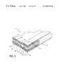
- FIG. 5is a sectional isometric view of the fluid separation assembly of the present invention.
- FIG. 6is an enlarged view of section A of the fluid separation assembly shown in FIG. 5;
- FIG. 7is a cross-sectional view of the fluid separation assembly of the present invention shown in FIG. 1 taken along line 7 — 7 ;
- FIG. 8is an isometric sectional diagrammatical view of a module employing several fluid separation assemblies of the present invention.
- FIG. 9is an enlarged section B of the module shown in FIG. 8 .
- FIGS. 1 and 2illustrate one embodiment of the fluid separation assembly 10 of the present invention, wherein FIG. 2 is an exploded view of the fluid separation assembly 10 shown in FIG. 1 .
- the fluid separation assembly 10comprises first membrane retainers 12 , a female membrane subassembly 14 , a first membrane gasket 16 , a first wire mesh membrane support 18 , second membrane retainers 20 , a slotted permeate plate 22 , a permeate rim 24 , a second wire mesh membrane support 28 , a second membrane gasket 30 and a male membrane subassembly 32 .
- the first retainers 12may be substantially flat ring members having an outside diameter equal to the diameter of the female and male membrane subassemblies 14 and 32 and a thickness of between approximately 0.001 inches and 0.060 inches.
- the first membrane retainers 12each have a centrally disposed opening 13 and 35 .
- the first membrane retainers 12may be made from Monel 400 (UNS N 04400); however, other materials that are compatible with the welding process, discussed below, may also be used. It will also be appreciated that while first retainers 12 are shown as comprising substantially annular members they may have other desired shapes and other thicknesses without departing from the spirit and scope of the present invention.
- FIG. 3is an exploded view of a female permeable membrane subassembly 14 .
- female membrane subassembly 14comprises a female gasket seat 36 , a hydrogen permeable membrane 38 , an inner diameter membrane gasket 40 and a center support washer 42 .
- the female gasket seat 36is a substantially flat ring member 44 having a raised face 46 extending around the ring member 44 and a centrally disposed opening 45 . It will be appreciated that while this embodiment is shown with gasket seats with this configuration, there may be other geometries of gasket seats specific to other gasket configurations or materials that may be used without departing from the spirit and the scope of the present invention.
- the female gasket seat 36may be made from Monel 400; however, other materials such as nickel, copper, nickel alloys, copper alloys, or other alloys that provide for compatible fusion with the chosen permeable membrane material during welding may be used.
- the hydrogen permeable membrane 38is a substantially planar member having a circular configuration, opposing sides 48 and a centrally disposed circular opening 50 .
- the inner diameter membrane gasket 40is also a flat ring member having a centrally disposed opening 51 .
- the inner diameter membrane gasket 40may be made from Monel 400 (UNS N 04400); however, other materials such as nickel, copper, nickel alloys, copper alloys, or other alloys that provide for compatible fusion with the chosen permeable membrane material during welding may be used.
- the center support washer 42is a flat ring member having a centrally disposed opening 53 .
- the center support washer 42may be made of Monel 400 (UNS N 04400); however, other materials such as nickel, copper, nickel alloys, copper alloys, or other alloys that provide for compatible fusion with the chosen permeable membrane material or alloy during welding may be used.
- the first and second membrane gaskets 16 and 30are each a substantially flat ring member having a centrally-disposed opening 55 and 57 , respectively.
- the first and second membrane gaskets 16 and 30may be made from Monel 400 alloy (UNS N 004400), nickel, copper, nickel alloys, copper alloys or other precious alloys or other alloys compatible with the weld that is used to join the components of the fluid separation assembly 10 and which is discussed below.
- the first and second membrane gaskets 16 and 30may have a thickness of between approximately 0.0005 inches to 0.005 inches. However, other gasket thicknesses could be employed.
- first and second wire mesh membrane supports 18 and 28are planar, ring-shaped members having centrally disposed openings 52 and 54 , respectively.
- the wire mesh membrane supports 18 and 28may be made from 316L stainless steel alloy with a mesh count of between approximately 19 to 1,000 mesh per inch, wherein the mesh count is chosen to be adequate to support the hydrogen permeable membranes 38 and 62 .
- the style of woven meshmay include a standard plain square weave, twill square weave, rectangular plain or twill weave or triangular plain or twill weave.
- One example of a mesh count that may be usedis 49 mesh per inch.
- the wire mesh membrane supports 18 and 28may be made of steel alloys, stainless steel alloys, nickel alloys or copper alloys.
- the wire meshmay be coated with a thin film that prevents intermetallic diffusion bonding (i.e., an intermetallic diffusion bonding barrier).
- the intermetallic diffusion bonding barriermay be a thin film containing at least one of an oxide, a nitride, a boride, a silicide, a carbide, or an aluminide and may be applied using a number of conventional methods, including but not limited to, physical vapor deposition (PVD), chemical vapor deposition, and plasma enhanced vapor deposition.
- PVDphysical vapor deposition
- the method of reactive sputteringa form of PVD, can be used to apply a thin oxide film of between approximately 600-700 angstroms to the wire mesh membrane supports 18 and 28 .
- a variety of oxides, nitrides, borides, silicides, carbides and aluminidesmay also be used for the thin film as well as any thin films that will be apparent to those of ordinary skill in the art.
- Using this form of PVDresults in a dense amorphous thin film having approximately the same mechanical strength as the bulk thin film material.
- the second membrane retainers 20each are a substantially flat ring member.
- One retainer 20has a centrally disposed opening 59 and retainer 20 has a centrally disposed opening 61 . See FIG. 2 .
- These retainers 20may be the same thickness as the first and second wire mesh membrane supports 18 and 28 .
- the second membrane retainers 20may be made from a material that is compatible with the weld, discussed below, such as Monel 400 (UNS N 004400) and nickel, copper, nickel alloys, copper alloys, precious metals or alloys, or other alloys that provide for compatible fusion with the chosen membrane material or alloy during welding may be used.
- the slotted permeate plate 22is a steel plate having a plurality of slots 56 extending radially and outwardly from a central opening 58 in the direction of the periphery of the slotted permeate plate 22 .
- the number of slots 56 in a slotted permeate plate 22may range from approximately 10 to 72. However, other suitable slot densities could conceivably be employed.
- the permeate plate rim 24is a substantially flat ring member having a centrally disposed opening 63 and an inner diameter larger than the outer diameter of the slotted permeate plate 22 .
- the permeate plate rim 24is made from Monel 400 (UNS N 04400); however, other materials can also be used such as nickel, copper, nickel alloys, copper alloys, precious metals or alloys or other alloys that provide for compatible fusion with the chosen membrane material or alloy during welding.
- FIG. 4is an exploded view of the male permeable membrane subassembly 32 .
- the male membrane subassembly 32comprises a male gasket seat 60 , a hydrogen permeable membrane 62 , an inner diameter membrane gasket 64 , and a center support washer 66 .
- the hydrogen permeable membranes 38 and 62may be made from at least one hydrogen permeable metal or an alloy containing at least one hydrogen permeable metal, preferably selected from the transition metals of groups VIIB or VIIIB of the Periodic Table.
- the hydrogen permeable membrane 62 , the inner diameter membrane gasket 64 , and the center support washer 66are similar in structure to the hydrogen permeable membrane 38 , the inner diameter membrane gasket 40 and the center support washer 42 , respectively, discussed above.
- the male gasket seat 60is a substantially planar ring member 68 having a circular protuberance 70 extending around a centrally disposed opening 72 .
- the female gasket seat 36 and the male gasket seat 60are made of a high strength alloy material that is compatible with the weld such as Monel 400.
- the inner diameter member gaskets 40 and 64are made from the same materials as the first and second outer diameter membrane gaskets 16 and 30 , discussed above.
- FIGS. 5 through 7are various cross-sectional views of the assembled fluid separation assembly 10 of the present invention, wherein FIG. 6 is an enlarged view of section A of the fluid separation assembly 10 shown in FIG. 5, and FIG. 7 is a cross-sectional plan view of the assembled fluid separation assembly 10 .
- the female membrane subassembly 14 and the male membrane subassembly 32are initially assembled.
- the female gasket seat 36 , the permeable membrane 38 , the inner diameter membrane gasket 40 and the center support washer 42are placed adjacent one another, as shown in FIG. 7, such that their central disposed openings 45 , 50 , 51 and 53 , respectively, are coaxially aligned.
- a first weld 71shown in FIG. 7, is placed at the openings thereof
- the first weld 71takes the form of a weld bead creating a hermetic seal between the female gasket seat 36 , the permeable membrane 38 , the inner diameter membrane gasket 40 and the center support washer 42 .
- the weld 71can be effected by a number of commercially available technologies, including but not limited to, lasers, electron beam and tungsten inert gas (TIG) welding. Alternative joining technologies such as brazing or soldering may also be employed with the desired result being a gas tight bond between the gasket seat 36 and the permeable membrane 38 .
- TOGtungsten inert gas
- the components of the male membrane subassembly 32which include the male gasket seat 60 , the permeable membrane 62 , the inner diameter membrane gasket 64 and the center support washer 66 are also placed adjacent one another, as shown in FIG. 7, such that their centrally disposed openings 72 , 81 , 83 and 85 are coaxially aligned with each other and a second weld bead 73 , shown in FIG. 7, is placed around the circumference of the openings 72 , 81 , 83 and 85 thereof.
- the weld 73can be effected by a number of commercially available technologies, including but not limited to, laser, electron beam, and tungsten inert gas (TIG) welding.
- the components of the female membrane subassembly 14 and the components of the male membrane subassembly 32are assembled with the other components described above to form the fluid separation assembly 10 .
- the first and second retainer members 12 and 20 , the female and male membrane subassemblies 14 and 32 , the first and second outer diameter gaskets 16 and 30 , the first and second wire mesh membrane supports 18 and 28 , the slotted permeate plate 22 and the permeate rim 24are aligned such that their centrally disposed openings are coaxially aligned.
- FIG. 2the first and second retainer members 12 and 20 , the female and male membrane subassemblies 14 and 32 , the first and second outer diameter gaskets 16 and 30 , the first and second wire mesh membrane supports 18 and 28 , the slotted permeate plate 22 and the permeate rim 24 are aligned such that their centrally disposed openings are coaxially aligned.
- these componentsare retained in that configuration by placing a weld 74 at the outer periphery of the first and second retainer members 12 and 20 , the female and male membrane subassemblies 14 and 32 , the first and second outer diameter membrane gaskets 16 and 30 , and the slotted permeate rim 24 .
- these partscould be assembled such that their centrally disposed openings are coaxially aligned, as shown in FIG. 7, and connected to one another by performing a brazing or soldering operation at the outer periphery of the first and second retainer members 12 and 20 , the female and male membrane subassemblies 14 and 32 , the first and second outer diameter membrane gaskets 16 and 30 and the slotted permeate rim 24 .
- the fluid separation assembly 10may have a thickness ranging from 0.010 inches to 0.125 inches, depending upon the thicknesses of the components employed.
- the gas mixtureis directed towards the permeable membranes 38 and 62 of the female membrane subassembly 14 and the male membrane subassembly 32 , respectively, in the directions D and E, as shown in FIG. 7 .
- the permeable membranes 38 and 64 of the female and male membrane subassemblies 14 and 32are shown in FIG. 7 as being spaced from the first and second wire mesh membrane supports 18 and 28 ; however, in use, the permeable membranes 38 and 62 are in contact with the first and second wire mesh membrane supports 18 and 28 and are supported thereby.
- the central openings of the components of the fluid separation assembly 10form a conduit 80 wherein the purified hydrogen is collected and transported to a desired location.
- the conduit 80may have a diameter of between approximately 0.25 inches and 1 inch. The diameter is determined by the components of the fluid separation assembly 10 and by the desire that the hydrogen flow be substantially unimpeded.
- the non-hydrogen gases in the gas mixtureare prevented from entering the fluid separation assembly 10 by the fluid permeable membranes 38 and 62 .
- the remainder of the hydrogen depleted gas mixtureis directed around the exterior of the fluid separation assembly 10 in this embodiment.
- FIGS. 8 and 9illustrate a module 85 employing several fluid separation assemblies 10 of the present invention, wherein FIG. 9 is an enlarged section B of the module 85 .
- Each of the fluid separation assemblies 10are shown as a solid body for clarity. However, each of the fluid separation assemblies 10 are the same as the fluid separation assemblies 10 shown in FIGS. 1-7.
- the module 85has a feed gas inlet 91 , a permeate outlet 90 and a discharge gas outlet 93 .
- the fluid separation assemblies 10are coaxially aligned.
- Distribution plates 87are sandwiched between and separate the fluid separation assemblies 10 .
- the distribution plates 87are positioned on a shoulder of the gasket seats 36 in such a manner that they are positioned equidistant from the planar surface of the permeable membrane assemblies 14 and 32 in successive fluid separation assemblies 10 .
- the distribution plates 87are not fixedly connected to the gasket seats 36 and 60 , but rather rest on a shoulder of the gasket seat 36 . There is sufficient clearance between the central opening of the redistribution plate 87 and the shoulder on the female gasket seat 36 that the redistribution plates 87 and the fluid separation assemblies 10 are allowed to position themselves inside the wall of the membrane housing independently of the position of the fluid separation assemblies 10 .
- Each distribution plate 87has openings 89 therein.
- the fluid separation assemblies 10are aligned one with the other such that each of the conduits 80 of the fluid separation assemblies 10 form a larger conduit 90 .
- the path of the gas mixture containing hydrogenrepresented by arrow G, enters the opening 89 and travels along the outer surface of the fluid separation assembly 10 , wherein some of the hydrogen of the gas mixture is free to enter the fluid separation assembly 10 by the permeable membranes 38 and 62 and is directed along path F into the larger conduit 90 and the remaining gas mixture follows arrow G and serpentines through the passageway, formed by the distribution plates 87 , the fluid separation assemblies 10 and the interior wall 92 of the module 85 .
- the gas mixtureAs the gas mixture travels through the passageway, it contacts the outer surfaces of several other fluid separation assemblies 10 , wherein more of the hydrogen remaining in the gas mixture permeates the permeable membranes 38 and 62 and follows the path F resulting in this purified hydrogen entering the larger conduit 90 .
- the remainder of the hydrogen depleted gas mixtureexits through a port 93 located at the opposite end of the module 85 after flowing over the entire stack of fluid separation membrane assemblies 10 .
Landscapes
- Chemical & Material Sciences (AREA)
- Engineering & Computer Science (AREA)
- Chemical Kinetics & Catalysis (AREA)
- Organic Chemistry (AREA)
- Analytical Chemistry (AREA)
- General Chemical & Material Sciences (AREA)
- Oil, Petroleum & Natural Gas (AREA)
- Combustion & Propulsion (AREA)
- Inorganic Chemistry (AREA)
- Manufacturing & Machinery (AREA)
- Separation Using Semi-Permeable Membranes (AREA)
Abstract
Description
Claims (37)
Priority Applications (20)
| Application Number | Priority Date | Filing Date | Title |
|---|---|---|---|
| US09/422,505US6602325B1 (en) | 1999-10-21 | 1999-10-21 | Fluid separation assembly |
| CA002351191ACA2351191C (en) | 1998-11-10 | 1999-11-10 | Hydrogen separation membrane |
| DE19983751TDE19983751B4 (en) | 1998-11-10 | 1999-11-10 | Hydrogen Segregation membrane |
| KR1020017005881AKR100592625B1 (en) | 1998-11-10 | 1999-11-10 | Hydrogen separation membrane |
| JP2000580728AJP2002529220A (en) | 1998-11-10 | 1999-11-10 | Hydrogen separation device |
| EP99961621AEP1137477B1 (en) | 1998-11-10 | 1999-11-10 | Hydrogen separation membrane assembly |
| CH00854/01ACH694150A5 (en) | 1998-11-10 | 1999-11-10 | Hydrogen separation membrane. |
| AU18158/00AAU767080B2 (en) | 1998-11-10 | 1999-11-10 | Hydrogen separation membrane |
| ES200150043AES2199663B1 (en) | 1998-11-10 | 1999-11-10 | HYDROGEN SEPARATION MEMBRANE. |
| PCT/US1999/026527WO2000027507A1 (en) | 1998-11-10 | 1999-11-10 | Hydrogen separation membrane |
| US09/560,314US6419726B1 (en) | 1999-10-21 | 2000-04-27 | Fluid separation assembly and fluid separation module |
| PCT/US2000/028591WO2001028662A1 (en) | 1999-10-21 | 2000-10-16 | Fluid separation assembly |
| AU10898/01AAU1089801A (en) | 1999-10-21 | 2000-10-16 | Fluid separation assembly |
| US10/399,631US6835232B2 (en) | 1998-11-10 | 2001-04-12 | Fluid separation assembly and fluid separation module |
| FI20010984AFI122170B (en) | 1998-11-10 | 2001-05-10 | Hydrogen separation membrane |
| SE0101634ASE526425C2 (en) | 1998-11-10 | 2001-05-10 | Membrane Separation Module, Membrane Separation Structure, Separation Procedure, and Method of Manufacturing a Membrane Separation Structure |
| DKPA200100737ADK177264B1 (en) | 1998-11-10 | 2001-05-10 | Hydrogen separation membrane |
| US10/050,057US20020124723A1 (en) | 1999-10-21 | 2002-01-14 | Fluid separation assembly |
| US10/243,018US6582499B2 (en) | 1998-11-10 | 2002-09-13 | Fluid separation assembly |
| DKPA201070550ADK178650B1 (en) | 1998-11-10 | 2010-12-17 | The hydrogen-separerings-membrane device |
Applications Claiming Priority (1)
| Application Number | Priority Date | Filing Date | Title |
|---|---|---|---|
| US09/422,505US6602325B1 (en) | 1999-10-21 | 1999-10-21 | Fluid separation assembly |
Related Child Applications (3)
| Application Number | Title | Priority Date | Filing Date |
|---|---|---|---|
| US09/560,314Continuation-In-PartUS6419726B1 (en) | 1998-11-10 | 2000-04-27 | Fluid separation assembly and fluid separation module |
| US10/050,057ContinuationUS20020124723A1 (en) | 1999-10-21 | 2002-01-14 | Fluid separation assembly |
| US10/243,018ContinuationUS6582499B2 (en) | 1998-11-10 | 2002-09-13 | Fluid separation assembly |
Publications (1)
| Publication Number | Publication Date |
|---|---|
| US6602325B1true US6602325B1 (en) | 2003-08-05 |
Family
ID=23675186
Family Applications (2)
| Application Number | Title | Priority Date | Filing Date |
|---|---|---|---|
| US09/422,505Expired - LifetimeUS6602325B1 (en) | 1998-11-10 | 1999-10-21 | Fluid separation assembly |
| US10/050,057AbandonedUS20020124723A1 (en) | 1999-10-21 | 2002-01-14 | Fluid separation assembly |
Family Applications After (1)
| Application Number | Title | Priority Date | Filing Date |
|---|---|---|---|
| US10/050,057AbandonedUS20020124723A1 (en) | 1999-10-21 | 2002-01-14 | Fluid separation assembly |
Country Status (3)
| Country | Link |
|---|---|
| US (2) | US6602325B1 (en) |
| AU (1) | AU1089801A (en) |
| WO (1) | WO2001028662A1 (en) |
Cited By (22)
| Publication number | Priority date | Publication date | Assignee | Title |
|---|---|---|---|---|
| US20040003720A1 (en)* | 2002-07-05 | 2004-01-08 | Daimlerchrysler Ag | Membrane module for hydrogen separation |
| US20040060437A1 (en)* | 1998-11-10 | 2004-04-01 | Frost Chester B | Fluid separation assembly and fluid separation module |
| US20040237785A1 (en)* | 2003-03-21 | 2004-12-02 | Gambro Lundia Ab | Device for protecting medical apparatus |
| US20050023219A1 (en)* | 2003-07-30 | 2005-02-03 | Phase Inc. | Filtration system with enhanced cleaning and dynamic fluid separation |
| US20050023207A1 (en)* | 2003-07-30 | 2005-02-03 | Phase Inc. | Filtration system and dynamic fluid separation method |
| WO2005016494A1 (en)* | 2003-08-11 | 2005-02-24 | Compagnie Europeenne Des Technologies De L'hydrogene (Ceth) | Method for assembling a gas separation membrane on a support |
| US20050076779A1 (en)* | 2001-09-26 | 2005-04-14 | Kinji Saijo | Gas separating unit and method for manufacturing the same |
| US20060060084A1 (en)* | 2004-09-20 | 2006-03-23 | Edlund David J | Hydrogen purification devices, components, and fuel processing systems containing the same |
| US20060162563A1 (en)* | 2002-08-02 | 2006-07-27 | Daimlerchryslter Ag | Membrane module for the separation of hydrogen and method for the production thereof |
| KR100668647B1 (en) | 2005-11-10 | 2007-01-16 | 한국에너지기술연구원 | Hydrogen Purification Module |
| US7282147B2 (en) | 2003-10-07 | 2007-10-16 | Phase Inc. | Cleaning hollow core membrane fibers using vibration |
| US7320750B2 (en) | 2003-03-11 | 2008-01-22 | Phase Inc. | Centrifuge with controlled discharge of dense material |
| US7335312B2 (en) | 2003-06-25 | 2008-02-26 | Phase Inc. | Centrifuge with combinations of multiple features |
| US20100064887A1 (en)* | 2008-09-16 | 2010-03-18 | Protonex Technology Corporation | Membrane support module for permeate separation in a fuel cell |
| US20100263538A1 (en)* | 2009-04-16 | 2010-10-21 | Devries Peter David | Hydrogen Purifier Module and Method for Forming the Same |
| US7972420B2 (en) | 2006-05-22 | 2011-07-05 | Idatech, Llc | Hydrogen-processing assemblies and hydrogen-producing systems and fuel cell systems including the same |
| US20120102706A1 (en)* | 2010-10-29 | 2012-05-03 | Michael Thomas Gallagher | Methods of Making Filter Apparatus and Fabricating a Porous Ceramic Article |
| US20130305672A1 (en)* | 2012-05-16 | 2013-11-21 | Purolator Filters Na Llc | Helical/Spiral Seal Air Filter |
| US8591622B2 (en) | 2010-10-29 | 2013-11-26 | Corning Incorporated | Filter apparatus with porous ceramic plates |
| US20170266590A1 (en)* | 2014-09-18 | 2017-09-21 | Sartorius Stedim Biotech Gmbh | Filtration module and method for producing same |
| US10476093B2 (en) | 2016-04-15 | 2019-11-12 | Chung-Hsin Electric & Machinery Mfg. Corp. | Membrane modules for hydrogen separation and fuel processors and fuel cell systems including the same |
| US11712655B2 (en) | 2020-11-30 | 2023-08-01 | H2 Powertech, Llc | Membrane-based hydrogen purifiers |
Families Citing this family (12)
| Publication number | Priority date | Publication date | Assignee | Title |
|---|---|---|---|---|
| US6319306B1 (en) | 2000-03-23 | 2001-11-20 | Idatech, Llc | Hydrogen-selective metal membrane modules and method of forming the same |
| US6537352B2 (en) | 1996-10-30 | 2003-03-25 | Idatech, Llc | Hydrogen purification membranes, components and fuel processing systems containing the same |
| US7195663B2 (en) | 1996-10-30 | 2007-03-27 | Idatech, Llc | Hydrogen purification membranes, components and fuel processing systems containing the same |
| US6494937B1 (en) | 2001-09-27 | 2002-12-17 | Idatech, Llc | Hydrogen purification devices, components and fuel processing systems containing the same |
| US6596057B2 (en)* | 1999-03-22 | 2003-07-22 | Idatech, Llc | Hydrogen-selective metal membranes, membrane modules, purification assemblies and methods of forming the same |
| US6767389B2 (en) | 1999-03-22 | 2004-07-27 | Idatech, Llc | Hydrogen-selective metal membranes, membrane modules, purification assemblies and methods of forming the same |
| US6569227B2 (en) | 2001-09-27 | 2003-05-27 | Idatech, Llc | Hydrogen purification devices, components and fuel processing systems containing the same |
| US6660069B2 (en)* | 2001-07-23 | 2003-12-09 | Toyota Jidosha Kabushiki Kaisha | Hydrogen extraction unit |
| KR100715103B1 (en)* | 2001-10-26 | 2007-05-07 | 에스케이 주식회사 | Hydrogen Purification Module |
| DE10222568B4 (en)* | 2002-05-17 | 2007-02-08 | W.C. Heraeus Gmbh | Composite membrane and process for its production |
| DE102004002742B4 (en)* | 2004-01-20 | 2005-12-08 | Hartmut Lederer | Regenerator of combustion exhaust gases with catalyst |
| US7601302B2 (en) | 2005-09-16 | 2009-10-13 | Idatech, Llc | Self-regulating feedstock delivery systems and hydrogen-generating fuel processing assemblies and fuel cell systems incorporating the same |
Citations (97)
| Publication number | Priority date | Publication date | Assignee | Title |
|---|---|---|---|---|
| US2824620A (en) | 1955-09-12 | 1958-02-25 | Universal Oil Prod Co | Purification of hydrogen utilizing hydrogen-permeable membranes |
| US3208198A (en) | 1962-07-26 | 1965-09-28 | Engelhard Ind Inc | Method for hydrogen diffusion |
| CA724479A (en)* | 1965-12-28 | P. Murphy Kevin | Process of separating helium and/or hydrogen from gaseous mixtures containing same | |
| US3336730A (en)* | 1964-11-17 | 1967-08-22 | Union Carbide Corp | Hydrogen continuous production method and apparatus |
| US3344586A (en)* | 1965-06-22 | 1967-10-03 | Engelhard Ind Inc | Gas separation apparatus |
| US3350176A (en) | 1964-03-24 | 1967-10-31 | Engelhard Ind Inc | Hydrogen generator |
| US3368329A (en) | 1965-08-10 | 1968-02-13 | Eguchi Takashi | Hydrogen purification apparatus |
| US3398834A (en)* | 1966-10-10 | 1968-08-27 | Aerojet General Co | Reverse osmosis water purification apparatus and cell therefor |
| US3428476A (en) | 1965-06-22 | 1969-02-18 | Engelhard Min & Chem | Method for producing hydrogen diffusion cells |
| US3439474A (en) | 1967-08-17 | 1969-04-22 | Union Carbide Corp | Method for hydrogen separation and purification |
| US3447288A (en) | 1965-08-23 | 1969-06-03 | Prototeck Inc | Gas-diffusion assembly including thin hydrogen-permeable impervious foil |
| US3450500A (en) | 1965-08-03 | 1969-06-17 | United Aircraft Corp | Method for catalytically reforming hydrogen-containing carbonaceous feed-stocks by simultaneous abstractions through a membrane selectively permeable to hydrogen |
| US3469944A (en) | 1968-05-13 | 1969-09-30 | Joseph P Bocard | Process and apparatus for the manufacture of hydrogen for fuel cells |
| US3486301A (en)* | 1968-08-05 | 1969-12-30 | Engelhard Min & Chem | Hydrogen diffusion apparatus |
| US3520803A (en) | 1968-12-24 | 1970-07-21 | Ionics | Membrane fluid separation apparatus and process |
| DE2005494A1 (en)* | 1969-02-07 | 1970-09-03 | Johnson, Matthey & Co. Ltd., London | PF 07 92.69 Great Britain 6724-69 Diffusion Device |
| US3564819A (en) | 1970-02-24 | 1971-02-23 | Gen Electric | Membrane package construction |
| US3665680A (en) | 1970-12-18 | 1972-05-30 | Engelhard Min & Chem | Hydrogen diffusion apparatus |
| US3713270A (en) | 1971-05-24 | 1973-01-30 | Nat Res Dev | Hydrogen diffusion membranes |
| US3761382A (en) | 1972-06-21 | 1973-09-25 | Triangle Environment Corp | Ers and the like apparatus for generating purifying and delivering hydrogen for analyz |
| US3837146A (en) | 1971-09-09 | 1974-09-24 | Rhone Poulenc Sa | Separating apparatus particularly suitable for gas permeation and in pervaporation |
| US3881897A (en) | 1972-11-24 | 1975-05-06 | Rhone Poulenc Sa | Apparatus for separating fluids |
| US3881891A (en) | 1973-02-05 | 1975-05-06 | Viktor Alexeevich Goltsov | Method for preparation of super-high purity hydrogen |
| US3972695A (en) | 1975-05-12 | 1976-08-03 | Trienco, Inc. | Hydrogen purifier |
| US4003725A (en) | 1975-05-12 | 1977-01-18 | Trienco, Inc. | Apparatus for purifying hydrogen gas |
| US4056373A (en) | 1976-05-12 | 1977-11-01 | Resource Systems, Inc. | Hydrogen-purification apparatus with palladium-alloy filter coil |
| US4132668A (en) | 1977-04-06 | 1979-01-02 | Gryaznov Vladimir M | Method of preparing a hydrogen-permeable membrane catalyst on a base of palladium or its alloys for the hydrogenation of unsaturated organic compounds |
| US4238403A (en) | 1975-03-03 | 1980-12-09 | Imperial Chemical Industries Limited | Methanol synthesis process |
| US4239728A (en) | 1978-02-02 | 1980-12-16 | Gambro Ab | Apparatus and method for the diffusion of substances between two fluids separated by a semipermeable membrane |
| US4243536A (en)* | 1977-12-01 | 1981-01-06 | Kilcher-Chemie Ag | Cross-flow filtration apparatus |
| US4248688A (en) | 1979-09-04 | 1981-02-03 | International Business Machines Corporation | Ion milling of thin metal films |
| US4254086A (en) | 1978-12-27 | 1981-03-03 | Sanders Alfred P | Endothermal water decomposition unit for producing hydrogen and oxygen |
| US4319923A (en) | 1979-12-26 | 1982-03-16 | Western Electric Co., Inc. | Recovery of gold and/or palladium from an iodide-iodine etching solution |
| US4331520A (en) | 1979-10-26 | 1982-05-25 | Prototech Company | Process for the recovery of hydrogen-reduced metals, ions and the like at porous hydrophobic catalytic barriers |
| US4422911A (en) | 1982-06-14 | 1983-12-27 | Prototech Company | Method of recovering hydrogen-reduced metals, ions and the like at porous catalytic barriers and apparatus therefor |
| US4468235A (en) | 1979-02-15 | 1984-08-28 | Hill Eugene F | Hydrogen separation using coated titanium alloys |
| US4472176A (en) | 1983-08-01 | 1984-09-18 | Resource Systems, Inc. | Apparatus and method for the production of pure hydrogen from a hydrogen-containing crude gas |
| US4589891A (en) | 1983-09-08 | 1986-05-20 | Kernforschungsanlage Julich Gesellschaft Mit Beschrankter Haftung | Hydrogen permeatin membrane, process for its manufacture and use |
| US4597868A (en)* | 1980-07-24 | 1986-07-01 | Terumo Corporation | Body fluid filter device |
| US4613436A (en) | 1984-10-31 | 1986-09-23 | Separex Corporation | Membrane assembly for fluid separations-disk |
| US4655797A (en) | 1983-09-08 | 1987-04-07 | Kernforschungsanlage Julich Gesellschaft Mit Beschrankter Haftung | Fine screen and fine screen stack, their use and process for the manufacture of fine screens |
| US4699637A (en) | 1983-09-08 | 1987-10-13 | Kernforschungsanlage Julich Gesellschaft Mit Beschrankter Haftung | Hydrogen permeation membrane |
| US4713234A (en) | 1984-06-30 | 1987-12-15 | Kernforschungsanlage Julich Gesellschaft Mit Beschrankter Haftung | Process and apparatus for conversion of water vapor with coal or hydrocarbon into a product gas |
| CA1238866A (en) | 1982-09-13 | 1988-07-05 | Johnson Matthey Public Limited Company | Diffusion cell |
| US4810485A (en) | 1986-08-25 | 1989-03-07 | Institute Of Gas Technology | Hydrogen forming reaction process |
| JPH01145303A (en) | 1987-11-30 | 1989-06-07 | Japan Pionics Co Ltd | Purification of hydrogen |
| JPH01145302A (en) | 1987-11-30 | 1989-06-07 | Japan Pionics Co Ltd | Hydrogen purification method and device |
| US4849187A (en) | 1987-03-31 | 1989-07-18 | Toyo Engineering Corporation | Steam reforming apparatus |
| JPH01262903A (en) | 1988-04-13 | 1989-10-19 | Showa Alum Corp | Method for producing filter membrane |
| US4981676A (en) | 1989-11-13 | 1991-01-01 | Minet Ronald G | Catalytic ceramic membrane steam/hydrocarbon reformer |
| GB2233579A (en)* | 1989-07-11 | 1991-01-16 | Smc Corp | Gas filter element |
| US4999107A (en) | 1988-10-17 | 1991-03-12 | Eurodia S.A. | Separator frame for a two-fluid exchanger device |
| US5126045A (en)* | 1989-10-16 | 1992-06-30 | Robert Kohlheb | Support plates with meandrical channels for diaphragm filtration |
| US5139541A (en) | 1990-08-10 | 1992-08-18 | Bend Research, Inc. | Hydrogen-permeable composite metal membrane |
| US5158581A (en) | 1991-07-29 | 1992-10-27 | Coplan Myron J | Fluid separation membrane module with hollow fibers having segregated active surface regions |
| US5205841A (en) | 1992-04-03 | 1993-04-27 | Tpc Technologies, Inc. | Apparatus and method for extracting hydrogen |
| US5215729A (en) | 1990-06-22 | 1993-06-01 | Buxbaum Robert E | Composite metal membrane for hydrogen extraction |
| US5217506A (en)* | 1990-08-10 | 1993-06-08 | Bend Research, Inc. | Hydrogen-permeable composite metal membrane and uses thereof |
| US5225080A (en)* | 1990-09-07 | 1993-07-06 | Seitz-Filter-Werke Theo & Geo Seitz Gmbh Und Co. | Filtration module and device for separating and filtering fluids in a crossflow process |
| US5229102A (en) | 1989-11-13 | 1993-07-20 | Medalert, Inc. | Catalytic ceramic membrane steam-hydrocarbon reformer |
| US5259870A (en)* | 1990-08-10 | 1993-11-09 | Bend Research, Inc. | Hydrogen-permeable composite metal membrane |
| US5269917A (en)* | 1992-02-28 | 1993-12-14 | Millipore Corporation | Filtration apparatus having stress relief groove |
| JPH06134244A (en) | 1992-10-20 | 1994-05-17 | Orion Mach Co Ltd | Membrane gas drier |
| US5326550A (en) | 1992-10-22 | 1994-07-05 | The University Of British Columbia | Fluidized bed reaction system for steam/hydrocarbon gas reforming to produce hydrogen |
| US5354547A (en) | 1989-11-14 | 1994-10-11 | Air Products And Chemicals, Inc. | Hydrogen recovery by adsorbent membranes |
| US5376167A (en) | 1991-12-19 | 1994-12-27 | Institut Francais Du Petrole | Purifying device for hydrogen comprising a base made of an alloy of the same composition as that of the tubes |
| US5393325A (en) | 1990-08-10 | 1995-02-28 | Bend Research, Inc. | Composite hydrogen separation metal membrane |
| US5449848A (en) | 1989-06-13 | 1995-09-12 | Agency Of Industrial Science And Technology | Dehydrogenation process |
| US5486475A (en) | 1993-02-10 | 1996-01-23 | Kramer; Valentin | Membrane module to remove gaseous substances from a gas stream |
| US5498278A (en)* | 1990-08-10 | 1996-03-12 | Bend Research, Inc. | Composite hydrogen separation element and module |
| US5500122A (en) | 1994-05-11 | 1996-03-19 | Uop | Stacked fluid-separation membrane disk module assemblies |
| US5518530A (en) | 1993-10-18 | 1996-05-21 | Ngk Insulators, Ltd. | Connected body comprising a gas separator and a metal, and apparatus for separating hydrogen gas from a mixed gas |
| US5520807A (en) | 1994-05-11 | 1996-05-28 | Uop | Stacked fluid-separation membrane disk module assemblies |
| US5525322A (en) | 1994-10-12 | 1996-06-11 | The Regents Of The University Of California | Method for simultaneous recovery of hydrogen from water and from hydrocarbons |
| US5536405A (en)* | 1994-05-11 | 1996-07-16 | Uop | Stacked membrane disk assemblies for fluid separations |
| US5639431A (en) | 1993-03-16 | 1997-06-17 | Tokyo Gas Co. Ltd. | Hydrogen producing apparatus |
| US5645626A (en) | 1990-08-10 | 1997-07-08 | Bend Research, Inc. | Composite hydrogen separation element and module |
| WO1997043796A1 (en) | 1996-05-10 | 1997-11-20 | Forschungszentrum Jülich GmbH | Membrane reactor for producing co- and co2-free hydrogen |
| US5734092A (en) | 1995-05-31 | 1998-03-31 | Hewlett-Packard Company | Planar palladium structure |
| US5738708A (en) | 1995-06-07 | 1998-04-14 | The Regents Of The University Of California Office Of Technology Transfer | Composite metal membrane |
| US5782960A (en) | 1996-03-18 | 1998-07-21 | Mitsubishi Jukogyo Kabushiki Kaisha | Hydrogen separation member |
| US5821185A (en) | 1994-01-14 | 1998-10-13 | Eltron Research, Inc. | Solid state proton and electron mediating membrane and use in catalytic membrane reactors |
| US5858314A (en) | 1996-04-12 | 1999-01-12 | Ztek Corporation | Thermally enhanced compact reformer |
| US5861137A (en) | 1996-10-30 | 1999-01-19 | Edlund; David J. | Steam reformer with internal hydrogen purification |
| US5888273A (en) | 1996-09-25 | 1999-03-30 | Buxbaum; Robert E. | High temperature gas purification system |
| US5891222A (en) | 1994-12-30 | 1999-04-06 | Gkss-Forschungszentrum Geesthacht Gmbh | Device for separating mixtures using stacked spaced membrane elements |
| US5904754A (en) | 1997-06-20 | 1999-05-18 | Walter Juda Associates | Diffusion-bonded palladium-copper alloy framed membrane for pure hydrogen generators and the like and method of preparing the same |
| WO1999030806A1 (en) | 1997-12-15 | 1999-06-24 | Worcester Polytechnic Institute | Hydrogen gas-extraction module |
| US5938800A (en) | 1997-11-13 | 1999-08-17 | Mcdermott Technology, Inc. | Compact multi-fuel steam reformer |
| US5965010A (en) | 1997-07-15 | 1999-10-12 | Niagara Mohawk Power Corporation | Electrochemical autothermal reformer |
| US5997594A (en) | 1996-10-30 | 1999-12-07 | Northwest Power Systems, Llc | Steam reformer with internal hydrogen purification |
| US6103028A (en) | 1999-02-18 | 2000-08-15 | Walter Juda Associates, Inc. | Method of fabricating thinned free-standing metallic hydrogen-selective palladium-bearing membranes and novel pin-hole-free membranes formed thereby |
| US6152995A (en) | 1999-03-22 | 2000-11-28 | Idatech Llc | Hydrogen-permeable metal membrane and method for producing the same |
| EP1065741A2 (en) | 1999-06-30 | 2001-01-03 | Mitsubishi Heavy Industries, Ltd. | Method for driving a fuel cell vehicle and fuel cell vehicle |
| US6171574B1 (en) | 1996-09-24 | 2001-01-09 | Walter Juda Associates, Inc. | Method of linking membrane purification of hydrogen to its generation by steam reforming of a methanol-like fuel |
| US6221117B1 (en) | 1996-10-30 | 2001-04-24 | Idatech, Llc | Hydrogen producing fuel processing system |
| US6238465B1 (en) | 1998-12-31 | 2001-05-29 | Walter Juda Associates, Inc. | Method of producing thin palladium-copper and the like, palladium alloy membranes by solid-solid metallic interdiffusion, and improved membrane |
- 1999
- 1999-10-21USUS09/422,505patent/US6602325B1/ennot_activeExpired - Lifetime
- 2000
- 2000-10-16AUAU10898/01Apatent/AU1089801A/ennot_activeAbandoned
- 2000-10-16WOPCT/US2000/028591patent/WO2001028662A1/enactiveApplication Filing
- 2002
- 2002-01-14USUS10/050,057patent/US20020124723A1/ennot_activeAbandoned
Patent Citations (97)
| Publication number | Priority date | Publication date | Assignee | Title |
|---|---|---|---|---|
| CA724479A (en)* | 1965-12-28 | P. Murphy Kevin | Process of separating helium and/or hydrogen from gaseous mixtures containing same | |
| US2824620A (en) | 1955-09-12 | 1958-02-25 | Universal Oil Prod Co | Purification of hydrogen utilizing hydrogen-permeable membranes |
| US3208198A (en) | 1962-07-26 | 1965-09-28 | Engelhard Ind Inc | Method for hydrogen diffusion |
| US3350176A (en) | 1964-03-24 | 1967-10-31 | Engelhard Ind Inc | Hydrogen generator |
| US3336730A (en)* | 1964-11-17 | 1967-08-22 | Union Carbide Corp | Hydrogen continuous production method and apparatus |
| US3344586A (en)* | 1965-06-22 | 1967-10-03 | Engelhard Ind Inc | Gas separation apparatus |
| US3428476A (en) | 1965-06-22 | 1969-02-18 | Engelhard Min & Chem | Method for producing hydrogen diffusion cells |
| US3450500A (en) | 1965-08-03 | 1969-06-17 | United Aircraft Corp | Method for catalytically reforming hydrogen-containing carbonaceous feed-stocks by simultaneous abstractions through a membrane selectively permeable to hydrogen |
| US3368329A (en) | 1965-08-10 | 1968-02-13 | Eguchi Takashi | Hydrogen purification apparatus |
| US3447288A (en) | 1965-08-23 | 1969-06-03 | Prototeck Inc | Gas-diffusion assembly including thin hydrogen-permeable impervious foil |
| US3398834A (en)* | 1966-10-10 | 1968-08-27 | Aerojet General Co | Reverse osmosis water purification apparatus and cell therefor |
| US3439474A (en) | 1967-08-17 | 1969-04-22 | Union Carbide Corp | Method for hydrogen separation and purification |
| US3469944A (en) | 1968-05-13 | 1969-09-30 | Joseph P Bocard | Process and apparatus for the manufacture of hydrogen for fuel cells |
| US3486301A (en)* | 1968-08-05 | 1969-12-30 | Engelhard Min & Chem | Hydrogen diffusion apparatus |
| US3520803A (en) | 1968-12-24 | 1970-07-21 | Ionics | Membrane fluid separation apparatus and process |
| DE2005494A1 (en)* | 1969-02-07 | 1970-09-03 | Johnson, Matthey & Co. Ltd., London | PF 07 92.69 Great Britain 6724-69 Diffusion Device |
| US3564819A (en) | 1970-02-24 | 1971-02-23 | Gen Electric | Membrane package construction |
| US3665680A (en) | 1970-12-18 | 1972-05-30 | Engelhard Min & Chem | Hydrogen diffusion apparatus |
| US3713270A (en) | 1971-05-24 | 1973-01-30 | Nat Res Dev | Hydrogen diffusion membranes |
| US3837146A (en) | 1971-09-09 | 1974-09-24 | Rhone Poulenc Sa | Separating apparatus particularly suitable for gas permeation and in pervaporation |
| US3761382A (en) | 1972-06-21 | 1973-09-25 | Triangle Environment Corp | Ers and the like apparatus for generating purifying and delivering hydrogen for analyz |
| US3881897A (en) | 1972-11-24 | 1975-05-06 | Rhone Poulenc Sa | Apparatus for separating fluids |
| US3881891A (en) | 1973-02-05 | 1975-05-06 | Viktor Alexeevich Goltsov | Method for preparation of super-high purity hydrogen |
| US4238403A (en) | 1975-03-03 | 1980-12-09 | Imperial Chemical Industries Limited | Methanol synthesis process |
| US4003725A (en) | 1975-05-12 | 1977-01-18 | Trienco, Inc. | Apparatus for purifying hydrogen gas |
| US3972695A (en) | 1975-05-12 | 1976-08-03 | Trienco, Inc. | Hydrogen purifier |
| US4056373A (en) | 1976-05-12 | 1977-11-01 | Resource Systems, Inc. | Hydrogen-purification apparatus with palladium-alloy filter coil |
| US4132668A (en) | 1977-04-06 | 1979-01-02 | Gryaznov Vladimir M | Method of preparing a hydrogen-permeable membrane catalyst on a base of palladium or its alloys for the hydrogenation of unsaturated organic compounds |
| US4243536A (en)* | 1977-12-01 | 1981-01-06 | Kilcher-Chemie Ag | Cross-flow filtration apparatus |
| US4239728A (en) | 1978-02-02 | 1980-12-16 | Gambro Ab | Apparatus and method for the diffusion of substances between two fluids separated by a semipermeable membrane |
| US4254086A (en) | 1978-12-27 | 1981-03-03 | Sanders Alfred P | Endothermal water decomposition unit for producing hydrogen and oxygen |
| US4468235A (en) | 1979-02-15 | 1984-08-28 | Hill Eugene F | Hydrogen separation using coated titanium alloys |
| US4248688A (en) | 1979-09-04 | 1981-02-03 | International Business Machines Corporation | Ion milling of thin metal films |
| US4331520A (en) | 1979-10-26 | 1982-05-25 | Prototech Company | Process for the recovery of hydrogen-reduced metals, ions and the like at porous hydrophobic catalytic barriers |
| US4319923A (en) | 1979-12-26 | 1982-03-16 | Western Electric Co., Inc. | Recovery of gold and/or palladium from an iodide-iodine etching solution |
| US4597868A (en)* | 1980-07-24 | 1986-07-01 | Terumo Corporation | Body fluid filter device |
| US4422911A (en) | 1982-06-14 | 1983-12-27 | Prototech Company | Method of recovering hydrogen-reduced metals, ions and the like at porous catalytic barriers and apparatus therefor |
| CA1238866A (en) | 1982-09-13 | 1988-07-05 | Johnson Matthey Public Limited Company | Diffusion cell |
| US4472176A (en) | 1983-08-01 | 1984-09-18 | Resource Systems, Inc. | Apparatus and method for the production of pure hydrogen from a hydrogen-containing crude gas |
| US4589891A (en) | 1983-09-08 | 1986-05-20 | Kernforschungsanlage Julich Gesellschaft Mit Beschrankter Haftung | Hydrogen permeatin membrane, process for its manufacture and use |
| US4655797A (en) | 1983-09-08 | 1987-04-07 | Kernforschungsanlage Julich Gesellschaft Mit Beschrankter Haftung | Fine screen and fine screen stack, their use and process for the manufacture of fine screens |
| US4699637A (en) | 1983-09-08 | 1987-10-13 | Kernforschungsanlage Julich Gesellschaft Mit Beschrankter Haftung | Hydrogen permeation membrane |
| US4713234A (en) | 1984-06-30 | 1987-12-15 | Kernforschungsanlage Julich Gesellschaft Mit Beschrankter Haftung | Process and apparatus for conversion of water vapor with coal or hydrocarbon into a product gas |
| US4613436A (en) | 1984-10-31 | 1986-09-23 | Separex Corporation | Membrane assembly for fluid separations-disk |
| US4810485A (en) | 1986-08-25 | 1989-03-07 | Institute Of Gas Technology | Hydrogen forming reaction process |
| US4849187A (en) | 1987-03-31 | 1989-07-18 | Toyo Engineering Corporation | Steam reforming apparatus |
| JPH01145303A (en) | 1987-11-30 | 1989-06-07 | Japan Pionics Co Ltd | Purification of hydrogen |
| JPH01145302A (en) | 1987-11-30 | 1989-06-07 | Japan Pionics Co Ltd | Hydrogen purification method and device |
| JPH01262903A (en) | 1988-04-13 | 1989-10-19 | Showa Alum Corp | Method for producing filter membrane |
| US4999107A (en) | 1988-10-17 | 1991-03-12 | Eurodia S.A. | Separator frame for a two-fluid exchanger device |
| US5449848A (en) | 1989-06-13 | 1995-09-12 | Agency Of Industrial Science And Technology | Dehydrogenation process |
| GB2233579A (en)* | 1989-07-11 | 1991-01-16 | Smc Corp | Gas filter element |
| US5126045A (en)* | 1989-10-16 | 1992-06-30 | Robert Kohlheb | Support plates with meandrical channels for diaphragm filtration |
| US5229102A (en) | 1989-11-13 | 1993-07-20 | Medalert, Inc. | Catalytic ceramic membrane steam-hydrocarbon reformer |
| US4981676A (en) | 1989-11-13 | 1991-01-01 | Minet Ronald G | Catalytic ceramic membrane steam/hydrocarbon reformer |
| US5354547A (en) | 1989-11-14 | 1994-10-11 | Air Products And Chemicals, Inc. | Hydrogen recovery by adsorbent membranes |
| US5215729A (en) | 1990-06-22 | 1993-06-01 | Buxbaum Robert E | Composite metal membrane for hydrogen extraction |
| US5217506A (en)* | 1990-08-10 | 1993-06-08 | Bend Research, Inc. | Hydrogen-permeable composite metal membrane and uses thereof |
| US5259870A (en)* | 1990-08-10 | 1993-11-09 | Bend Research, Inc. | Hydrogen-permeable composite metal membrane |
| US5139541A (en) | 1990-08-10 | 1992-08-18 | Bend Research, Inc. | Hydrogen-permeable composite metal membrane |
| US5645626A (en) | 1990-08-10 | 1997-07-08 | Bend Research, Inc. | Composite hydrogen separation element and module |
| US5498278A (en)* | 1990-08-10 | 1996-03-12 | Bend Research, Inc. | Composite hydrogen separation element and module |
| US5393325A (en) | 1990-08-10 | 1995-02-28 | Bend Research, Inc. | Composite hydrogen separation metal membrane |
| US5225080A (en)* | 1990-09-07 | 1993-07-06 | Seitz-Filter-Werke Theo & Geo Seitz Gmbh Und Co. | Filtration module and device for separating and filtering fluids in a crossflow process |
| US5158581A (en) | 1991-07-29 | 1992-10-27 | Coplan Myron J | Fluid separation membrane module with hollow fibers having segregated active surface regions |
| US5376167A (en) | 1991-12-19 | 1994-12-27 | Institut Francais Du Petrole | Purifying device for hydrogen comprising a base made of an alloy of the same composition as that of the tubes |
| US5269917A (en)* | 1992-02-28 | 1993-12-14 | Millipore Corporation | Filtration apparatus having stress relief groove |
| US5205841A (en) | 1992-04-03 | 1993-04-27 | Tpc Technologies, Inc. | Apparatus and method for extracting hydrogen |
| JPH06134244A (en) | 1992-10-20 | 1994-05-17 | Orion Mach Co Ltd | Membrane gas drier |
| US5326550A (en) | 1992-10-22 | 1994-07-05 | The University Of British Columbia | Fluidized bed reaction system for steam/hydrocarbon gas reforming to produce hydrogen |
| US5486475A (en) | 1993-02-10 | 1996-01-23 | Kramer; Valentin | Membrane module to remove gaseous substances from a gas stream |
| US5639431A (en) | 1993-03-16 | 1997-06-17 | Tokyo Gas Co. Ltd. | Hydrogen producing apparatus |
| US5518530A (en) | 1993-10-18 | 1996-05-21 | Ngk Insulators, Ltd. | Connected body comprising a gas separator and a metal, and apparatus for separating hydrogen gas from a mixed gas |
| US5821185A (en) | 1994-01-14 | 1998-10-13 | Eltron Research, Inc. | Solid state proton and electron mediating membrane and use in catalytic membrane reactors |
| US5500122A (en) | 1994-05-11 | 1996-03-19 | Uop | Stacked fluid-separation membrane disk module assemblies |
| US5520807A (en) | 1994-05-11 | 1996-05-28 | Uop | Stacked fluid-separation membrane disk module assemblies |
| US5536405A (en)* | 1994-05-11 | 1996-07-16 | Uop | Stacked membrane disk assemblies for fluid separations |
| US5525322A (en) | 1994-10-12 | 1996-06-11 | The Regents Of The University Of California | Method for simultaneous recovery of hydrogen from water and from hydrocarbons |
| US5891222A (en) | 1994-12-30 | 1999-04-06 | Gkss-Forschungszentrum Geesthacht Gmbh | Device for separating mixtures using stacked spaced membrane elements |
| US5734092A (en) | 1995-05-31 | 1998-03-31 | Hewlett-Packard Company | Planar palladium structure |
| US5738708A (en) | 1995-06-07 | 1998-04-14 | The Regents Of The University Of California Office Of Technology Transfer | Composite metal membrane |
| US5782960A (en) | 1996-03-18 | 1998-07-21 | Mitsubishi Jukogyo Kabushiki Kaisha | Hydrogen separation member |
| US5858314A (en) | 1996-04-12 | 1999-01-12 | Ztek Corporation | Thermally enhanced compact reformer |
| WO1997043796A1 (en) | 1996-05-10 | 1997-11-20 | Forschungszentrum Jülich GmbH | Membrane reactor for producing co- and co2-free hydrogen |
| US6171574B1 (en) | 1996-09-24 | 2001-01-09 | Walter Juda Associates, Inc. | Method of linking membrane purification of hydrogen to its generation by steam reforming of a methanol-like fuel |
| US5888273A (en) | 1996-09-25 | 1999-03-30 | Buxbaum; Robert E. | High temperature gas purification system |
| US5997594A (en) | 1996-10-30 | 1999-12-07 | Northwest Power Systems, Llc | Steam reformer with internal hydrogen purification |
| US5861137A (en) | 1996-10-30 | 1999-01-19 | Edlund; David J. | Steam reformer with internal hydrogen purification |
| US6221117B1 (en) | 1996-10-30 | 2001-04-24 | Idatech, Llc | Hydrogen producing fuel processing system |
| US5904754A (en) | 1997-06-20 | 1999-05-18 | Walter Juda Associates | Diffusion-bonded palladium-copper alloy framed membrane for pure hydrogen generators and the like and method of preparing the same |
| US5965010A (en) | 1997-07-15 | 1999-10-12 | Niagara Mohawk Power Corporation | Electrochemical autothermal reformer |
| US5938800A (en) | 1997-11-13 | 1999-08-17 | Mcdermott Technology, Inc. | Compact multi-fuel steam reformer |
| WO1999030806A1 (en) | 1997-12-15 | 1999-06-24 | Worcester Polytechnic Institute | Hydrogen gas-extraction module |
| US6238465B1 (en) | 1998-12-31 | 2001-05-29 | Walter Juda Associates, Inc. | Method of producing thin palladium-copper and the like, palladium alloy membranes by solid-solid metallic interdiffusion, and improved membrane |
| US6103028A (en) | 1999-02-18 | 2000-08-15 | Walter Juda Associates, Inc. | Method of fabricating thinned free-standing metallic hydrogen-selective palladium-bearing membranes and novel pin-hole-free membranes formed thereby |
| US6152995A (en) | 1999-03-22 | 2000-11-28 | Idatech Llc | Hydrogen-permeable metal membrane and method for producing the same |
| EP1065741A2 (en) | 1999-06-30 | 2001-01-03 | Mitsubishi Heavy Industries, Ltd. | Method for driving a fuel cell vehicle and fuel cell vehicle |
Non-Patent Citations (13)
| Title |
|---|
| Edlund, David J. and William A. Pledger, "The Practical Use of Metal-Membrane Reactors for Industrial Applications," The 1995 Membrane Technology Reviews, pp. 89-97 (Nov. 1994). |
| English abstract of Japanese Patent No. 11116202, 1999. |
| English abstract of Japanese Patent No. 1-262903, 1989. |
| English abstract of Japanese Patent No. 432150, 1992. |
| English abstract of Japanese Patent No. 513230, 1993. |
| English abstract of Japanese Patent No. 514790, 1993. |
| English abstract of Japanese Patent No. 604070, 1994. |
| English abstract of Japanese Patent No. 634540, 1994. |
| English abstract of Japanese Patent No.710910, 1995. |
| Knapton, A.G., "Palladuim Alloys for Hydrogen Diffusion Memvranes," Platinum Metals Review, vol. 21,44-50 (1977). |
| Minet, R.G., et al., "Experimental Studies of A Ceramic Membrane Reactor for the Steam/Methane Reaction at Moderate Temperatures (400-700°C)," Symposium on Natural Gas Upgrading II Presented before the Division of Petroleum Chemistry, Inc., Meeting of American Chemical Society, San Francisco, California, U.S.A., pp. 245-48 (Apr., 1992). |
| Oertel, Michael, et al., "Steam Reforming of Natural Gas with Integrated Hydrogen Separation for Hydrogen Production," Chemical Engineering Technology, vol. 10, pp. 248-55 (1987). |
| Shu, et al., "Catalyti Palladoim-Based Membrane Reactors: A Review," the Canadian Journal of Chemical Engineering, vol. 69, pp. 1036-60 (Oct. 1991). |
Cited By (41)
| Publication number | Priority date | Publication date | Assignee | Title |
|---|---|---|---|---|
| US20040060437A1 (en)* | 1998-11-10 | 2004-04-01 | Frost Chester B | Fluid separation assembly and fluid separation module |
| US6835232B2 (en) | 1998-11-10 | 2004-12-28 | Frost Chester B | Fluid separation assembly and fluid separation module |
| US20050076779A1 (en)* | 2001-09-26 | 2005-04-14 | Kinji Saijo | Gas separating unit and method for manufacturing the same |
| US7033641B2 (en)* | 2001-09-26 | 2006-04-25 | Toyo Kohan Co., Ltd. | Gas separating unit and method for manufacturing the same |
| US20040003720A1 (en)* | 2002-07-05 | 2004-01-08 | Daimlerchrysler Ag | Membrane module for hydrogen separation |
| US7056369B2 (en)* | 2002-07-05 | 2006-06-06 | Daimlerchrysler Ag | Membrane module for hydrogen separation |
| US7323040B2 (en)* | 2002-08-02 | 2008-01-29 | Daimlerchrysler Ag | Membrane module for the separation of hydrogen and method for the production thereof |
| US20060162563A1 (en)* | 2002-08-02 | 2006-07-27 | Daimlerchryslter Ag | Membrane module for the separation of hydrogen and method for the production thereof |
| US7320750B2 (en) | 2003-03-11 | 2008-01-22 | Phase Inc. | Centrifuge with controlled discharge of dense material |
| US20070084779A1 (en)* | 2003-03-21 | 2007-04-19 | Gambro Lundia Ab | Device for protecting medical apparatus |
| US7621983B2 (en)* | 2003-03-21 | 2009-11-24 | Gambro Lundia Ab | Transduction-protection device |
| US20040237785A1 (en)* | 2003-03-21 | 2004-12-02 | Gambro Lundia Ab | Device for protecting medical apparatus |
| US7175697B2 (en)* | 2003-03-21 | 2007-02-13 | Gambro Lundia Ab | Device for protecting medical apparatus |
| US7335312B2 (en) | 2003-06-25 | 2008-02-26 | Phase Inc. | Centrifuge with combinations of multiple features |
| US20050023219A1 (en)* | 2003-07-30 | 2005-02-03 | Phase Inc. | Filtration system with enhanced cleaning and dynamic fluid separation |
| US7294274B2 (en) | 2003-07-30 | 2007-11-13 | Phase Inc. | Filtration system with enhanced cleaning and dynamic fluid separation |
| US7371322B2 (en)* | 2003-07-30 | 2008-05-13 | Phase Inc. | Filtration system and dynamic fluid separation method |
| US20050023207A1 (en)* | 2003-07-30 | 2005-02-03 | Phase Inc. | Filtration system and dynamic fluid separation method |
| WO2005016494A1 (en)* | 2003-08-11 | 2005-02-24 | Compagnie Europeenne Des Technologies De L'hydrogene (Ceth) | Method for assembling a gas separation membrane on a support |
| US7282147B2 (en) | 2003-10-07 | 2007-10-16 | Phase Inc. | Cleaning hollow core membrane fibers using vibration |
| US20070295674A1 (en)* | 2003-10-07 | 2007-12-27 | Curtis Kirker | Cleaning hollow core membrane fibers using vibration |
| US20080115669A1 (en)* | 2004-09-20 | 2008-05-22 | Edlund David J | Hydrogen purification devices, components, and fuel processing systems containing the same |
| US20060060084A1 (en)* | 2004-09-20 | 2006-03-23 | Edlund David J | Hydrogen purification devices, components, and fuel processing systems containing the same |
| US7297183B2 (en) | 2004-09-20 | 2007-11-20 | Idatech, Llc | Hydrogen purification devices, components, and fuel processing systems containing the same |
| KR100668647B1 (en) | 2005-11-10 | 2007-01-16 | 한국에너지기술연구원 | Hydrogen Purification Module |
| US7972420B2 (en) | 2006-05-22 | 2011-07-05 | Idatech, Llc | Hydrogen-processing assemblies and hydrogen-producing systems and fuel cell systems including the same |
| US8157900B2 (en) | 2006-05-22 | 2012-04-17 | Idatech, Llc | Hydrogen-processing assemblies and hydrogen-producing systems and fuel cell systems including the same |
| US8603219B2 (en) | 2008-09-16 | 2013-12-10 | Protonex Technology Corporation | Membrane support module for permeate separation in a fuel cell |
| US20100064887A1 (en)* | 2008-09-16 | 2010-03-18 | Protonex Technology Corporation | Membrane support module for permeate separation in a fuel cell |
| US8465569B2 (en)* | 2008-09-16 | 2013-06-18 | Protonex Technology Corporation | Membrane support module for permeate separation in a fuel cell |
| US20100263538A1 (en)* | 2009-04-16 | 2010-10-21 | Devries Peter David | Hydrogen Purifier Module and Method for Forming the Same |
| US8110022B2 (en) | 2009-04-16 | 2012-02-07 | Genesis Fueltech, Inc. | Hydrogen purifier module and method for forming the same |
| US20120102706A1 (en)* | 2010-10-29 | 2012-05-03 | Michael Thomas Gallagher | Methods of Making Filter Apparatus and Fabricating a Porous Ceramic Article |
| US8590158B2 (en)* | 2010-10-29 | 2013-11-26 | Corning Incorporated | Methods of making filter apparatus and fabricating a porous ceramic article |
| US8591622B2 (en) | 2010-10-29 | 2013-11-26 | Corning Incorporated | Filter apparatus with porous ceramic plates |
| US20130305672A1 (en)* | 2012-05-16 | 2013-11-21 | Purolator Filters Na Llc | Helical/Spiral Seal Air Filter |
| US20170266590A1 (en)* | 2014-09-18 | 2017-09-21 | Sartorius Stedim Biotech Gmbh | Filtration module and method for producing same |
| US10589194B2 (en)* | 2014-09-18 | 2020-03-17 | Sumitomo Wiring Systems, Ltd. | Filtration module and method for producing same |
| US10476093B2 (en) | 2016-04-15 | 2019-11-12 | Chung-Hsin Electric & Machinery Mfg. Corp. | Membrane modules for hydrogen separation and fuel processors and fuel cell systems including the same |
| US11712655B2 (en) | 2020-11-30 | 2023-08-01 | H2 Powertech, Llc | Membrane-based hydrogen purifiers |
| US12226732B2 (en) | 2020-11-30 | 2025-02-18 | H2 Powertech, Llc | Membrane-based hydrogen purifiers |
Also Published As
| Publication number | Publication date |
|---|---|
| WO2001028662A1 (en) | 2001-04-26 |
| AU1089801A (en) | 2001-04-30 |
| US20020124723A1 (en) | 2002-09-12 |
Similar Documents
| Publication | Publication Date | Title |
|---|---|---|
| US6602325B1 (en) | Fluid separation assembly | |
| US6582499B2 (en) | Fluid separation assembly | |
| JP2002529220A5 (en) | ||
| US6419726B1 (en) | Fluid separation assembly and fluid separation module | |
| US8603219B2 (en) | Membrane support module for permeate separation in a fuel cell | |
| US3534531A (en) | Assembly of pure gas permeating separator | |
| US6835232B2 (en) | Fluid separation assembly and fluid separation module | |
| EP0547959B1 (en) | Hydrogen cleaner comprising a base made with an alloy of similar composition to that of the tubes | |
| US5782960A (en) | Hydrogen separation member | |
| EP2147897B1 (en) | Hydrogen separator and method of operating hydrogen separator | |
| JP4944656B2 (en) | Membrane support for hydrogen separation and module for hydrogen separation using this support | |
| US8226750B2 (en) | Hydrogen purifier module with membrane support | |
| CA1238866A (en) | Diffusion cell | |
| JP2008155118A (en) | Composite membrane for separating hydrogen and module for separating hydrogen using this hydrogen permeable membrane | |
| US3410058A (en) | Hydrogen diffuser-purifier | |
| JP2002518167A (en) | Purification assembly and purification method | |
| JPH10297905A (en) | Plate type hydrogen separation membrane module | |
| WO2000053289A1 (en) | Purifier assemblies |
Legal Events
| Date | Code | Title | Description |
|---|---|---|---|
| AS | Assignment | Owner name:ATI PROPERTIES, INC., PENNSYLVANIA Free format text:ASSIGNMENT OF ASSIGNORS INTEREST;ASSIGNORS:FROST, CHESTER B.;KRUEGER, BRETT R.;REEL/FRAME:012792/0594 Effective date:19991110 | |
| AS | Assignment | Owner name:ATI PROPERTIES, INC., PENNSYLVANIA Free format text:ASSIGNMENT OF ASSIGNORS INTEREST;ASSIGNORS:FROST, CHESTER B.;KRUEGER, BRETT R.;REEL/FRAME:013831/0422 Effective date:19991110 | |
| AS | Assignment | Owner name:PNC BANK, NATIONAL ASSOCIATION, PENNSYLVANIA Free format text:SECURITY INTEREST;ASSIGNOR:ATI PROPERTIES, INC.;REEL/FRAME:014186/0295 Effective date:20030613 | |
| STCF | Information on status: patent grant | Free format text:PATENTED CASE | |
| AS | Assignment | Owner name:PNC BANK, NATIONAL ASSOCIATION, PENNSYLVANIA Free format text:SECURITY AGREEMENT;ASSIGNOR:ATI PROPERTIES, INC.;REEL/FRAME:014830/0265 Effective date:20030613 | |
| FPAY | Fee payment | Year of fee payment:4 | |
| CC | Certificate of correction | ||
| CC | Certificate of correction | ||
| FPAY | Fee payment | Year of fee payment:8 | |
| AS | Assignment | Owner name:ATI PROPERTIES, INC., OREGON Free format text:RELEASE BY SECURED PARTY;ASSIGNOR:PNC BANK, NATIONAL ASSOCIATION, AS AGENT FOR THE LENDERS;REEL/FRAME:025845/0321 Effective date:20110217 | |
| FPAY | Fee payment | Year of fee payment:12 |