US6602247B2 - Apparatus and method for performing a treatment on a selected tissue region - Google Patents
Apparatus and method for performing a treatment on a selected tissue regionDownload PDFInfo
- Publication number
- US6602247B2 US6602247B2US10/016,190US1619002AUS6602247B2US 6602247 B2US6602247 B2US 6602247B2US 1619002 AUS1619002 AUS 1619002AUS 6602247 B2US6602247 B2US 6602247B2
- Authority
- US
- United States
- Prior art keywords
- fluid
- thermally
- fluid transport
- medical device
- transmissive region
- Prior art date
- Legal status (The legal status is an assumption and is not a legal conclusion. Google has not performed a legal analysis and makes no representation as to the accuracy of the status listed.)
- Expired - Lifetime
Links
- 238000000034methodMethods0.000titleclaimsdescription40
- 238000011282treatmentMethods0.000titleclaimsdescription22
- 239000012530fluidSubstances0.000claimsabstractdescription246
- 239000012528membraneSubstances0.000claimsdescription7
- 230000003247decreasing effectEffects0.000claimsdescription6
- 230000001225therapeutic effectEffects0.000claimsdescription3
- 230000003213activating effectEffects0.000claimsdescription2
- 230000004071biological effectEffects0.000claims1
- 210000001519tissueAnatomy0.000description55
- 238000002347injectionMethods0.000description41
- 239000007924injectionSubstances0.000description41
- 230000003902lesionEffects0.000description23
- 238000001816coolingMethods0.000description17
- 238000002679ablationMethods0.000description16
- 238000012546transferMethods0.000description14
- 239000000463materialSubstances0.000description13
- 239000012809cooling fluidSubstances0.000description6
- 239000007788liquidSubstances0.000description6
- 230000033001locomotionEffects0.000description6
- 230000008901benefitEffects0.000description5
- 238000013507mappingMethods0.000description5
- 239000002184metalSubstances0.000description5
- 229910052751metalInorganic materials0.000description5
- 230000000694effectsEffects0.000description4
- 210000005003heart tissueAnatomy0.000description4
- 230000008569processEffects0.000description4
- 230000008859changeEffects0.000description3
- 239000007787solidSubstances0.000description3
- CURLTUGMZLYLDI-UHFFFAOYSA-NCarbon dioxideChemical compoundO=C=OCURLTUGMZLYLDI-UHFFFAOYSA-N0.000description2
- RYGMFSIKBFXOCR-UHFFFAOYSA-NCopperChemical compound[Cu]RYGMFSIKBFXOCR-UHFFFAOYSA-N0.000description2
- LFQSCWFLJHTTHZ-UHFFFAOYSA-NEthanolChemical compoundCCOLFQSCWFLJHTTHZ-UHFFFAOYSA-N0.000description2
- GQPLMRYTRLFLPF-UHFFFAOYSA-NNitrous OxideChemical compound[O-][N+]#NGQPLMRYTRLFLPF-UHFFFAOYSA-N0.000description2
- 206010003119arrhythmiaDiseases0.000description2
- 239000000560biocompatible materialSubstances0.000description2
- 230000005540biological transmissionEffects0.000description2
- 230000000747cardiac effectEffects0.000description2
- 238000004891communicationMethods0.000description2
- 229910052802copperInorganic materials0.000description2
- 239000010949copperSubstances0.000description2
- RWRIWBAIICGTTQ-UHFFFAOYSA-NdifluoromethaneChemical compoundFCFRWRIWBAIICGTTQ-UHFFFAOYSA-N0.000description2
- 239000000203mixtureSubstances0.000description2
- 238000012986modificationMethods0.000description2
- 230000004048modificationEffects0.000description2
- 230000007935neutral effectEffects0.000description2
- 210000000056organAnatomy0.000description2
- 239000004810polytetrafluoroethyleneSubstances0.000description2
- 229920001343polytetrafluoroethylenePolymers0.000description2
- 238000007674radiofrequency ablationMethods0.000description2
- 230000004044responseEffects0.000description2
- 229910001220stainless steelInorganic materials0.000description2
- 239000010935stainless steelSubstances0.000description2
- 238000011269treatment regimenMethods0.000description2
- 229910000906BronzeInorganic materials0.000description1
- VOPWNXZWBYDODV-UHFFFAOYSA-NChlorodifluoromethaneChemical compoundFC(F)ClVOPWNXZWBYDODV-UHFFFAOYSA-N0.000description1
- 206010061218InflammationDiseases0.000description1
- 206010028980NeoplasmDiseases0.000description1
- 206010061876ObstructionDiseases0.000description1
- 239000004952PolyamideSubstances0.000description1
- 229920002614Polyether block amidePolymers0.000description1
- 208000005392SpasmDiseases0.000description1
- 238000002399angioplastyMethods0.000description1
- 238000013459approachMethods0.000description1
- 230000006793arrhythmiaEffects0.000description1
- 210000001367arteryAnatomy0.000description1
- 230000001746atrial effectEffects0.000description1
- 238000005452bendingMethods0.000description1
- 230000033228biological regulationEffects0.000description1
- 230000000740bleeding effectEffects0.000description1
- 210000004204blood vesselAnatomy0.000description1
- 238000009835boilingMethods0.000description1
- 239000010974bronzeSubstances0.000description1
- 201000011510cancerDiseases0.000description1
- 229910002092carbon dioxideInorganic materials0.000description1
- 239000001569carbon dioxideSubstances0.000description1
- 210000005242cardiac chamberAnatomy0.000description1
- 238000013153catheter ablationMethods0.000description1
- 230000000295complement effectEffects0.000description1
- 239000004020conductorSubstances0.000description1
- 230000001276controlling effectEffects0.000description1
- KUNSUQLRTQLHQQ-UHFFFAOYSA-Ncopper tinChemical compound[Cu].[Sn]KUNSUQLRTQLHQQ-UHFFFAOYSA-N0.000description1
- 210000003748coronary sinusAnatomy0.000description1
- 230000007812deficiencyEffects0.000description1
- 230000000994depressogenic effectEffects0.000description1
- 239000004205dimethyl polysiloxaneSubstances0.000description1
- 229920001971elastomerPolymers0.000description1
- 239000000806elastomerSubstances0.000description1
- 235000019441ethanolNutrition0.000description1
- 230000006870functionEffects0.000description1
- 210000001035gastrointestinal tractAnatomy0.000description1
- PCHJSUWPFVWCPO-UHFFFAOYSA-NgoldChemical compound[Au]PCHJSUWPFVWCPO-UHFFFAOYSA-N0.000description1
- 239000010931goldSubstances0.000description1
- 229910052737goldInorganic materials0.000description1
- 238000003384imaging methodMethods0.000description1
- 230000004054inflammatory processEffects0.000description1
- 238000003780insertionMethods0.000description1
- 230000037431insertionEffects0.000description1
- 239000004816latexSubstances0.000description1
- 229920000126latexPolymers0.000description1
- 230000036210malignancyEffects0.000description1
- 230000013011matingEffects0.000description1
- 238000002324minimally invasive surgeryMethods0.000description1
- HLXZNVUGXRDIFK-UHFFFAOYSA-Nnickel titaniumChemical compound[Ti].[Ti].[Ti].[Ti].[Ti].[Ti].[Ti].[Ti].[Ti].[Ti].[Ti].[Ni].[Ni].[Ni].[Ni].[Ni].[Ni].[Ni].[Ni].[Ni].[Ni].[Ni].[Ni].[Ni].[Ni]HLXZNVUGXRDIFK-UHFFFAOYSA-N0.000description1
- 229910001000nickel titaniumInorganic materials0.000description1
- 239000001272nitrous oxideSubstances0.000description1
- 230000037361pathwayEffects0.000description1
- GTLACDSXYULKMZ-UHFFFAOYSA-NpentafluoroethaneChemical compoundFC(F)C(F)(F)FGTLACDSXYULKMZ-UHFFFAOYSA-N0.000description1
- 229920000435poly(dimethylsiloxane)Polymers0.000description1
- 229920002647polyamidePolymers0.000description1
- -1polydimethylsiloxanePolymers0.000description1
- 229920000139polyethylene terephthalatePolymers0.000description1
- 239000005020polyethylene terephthalateSubstances0.000description1
- 229920000642polymerPolymers0.000description1
- 229920001296polysiloxanePolymers0.000description1
- 230000001105regulatory effectEffects0.000description1
- 238000011160researchMethods0.000description1
- 239000012858resilient materialSubstances0.000description1
- 208000037803restenosisDiseases0.000description1
- 238000001356surgical procedureMethods0.000description1
- 238000012360testing methodMethods0.000description1
- 230000000451tissue damageEffects0.000description1
- 231100000827tissue damageToxicity0.000description1
- 230000002861ventricularEffects0.000description1
Images


Classifications
- A—HUMAN NECESSITIES
- A61—MEDICAL OR VETERINARY SCIENCE; HYGIENE
- A61M—DEVICES FOR INTRODUCING MEDIA INTO, OR ONTO, THE BODY; DEVICES FOR TRANSDUCING BODY MEDIA OR FOR TAKING MEDIA FROM THE BODY; DEVICES FOR PRODUCING OR ENDING SLEEP OR STUPOR
- A61M25/00—Catheters; Hollow probes
- A61M25/0021—Catheters; Hollow probes characterised by the form of the tubing
- A61M25/0023—Catheters; Hollow probes characterised by the form of the tubing by the form of the lumen, e.g. cross-section, variable diameter
- A61M25/0026—Multi-lumen catheters with stationary elements
- A61M25/0029—Multi-lumen catheters with stationary elements characterized by features relating to least one lumen located at the middle part of the catheter, e.g. slots, flaps, valves, cuffs, apertures, notches, grooves or rapid exchange ports
- A—HUMAN NECESSITIES
- A61—MEDICAL OR VETERINARY SCIENCE; HYGIENE
- A61B—DIAGNOSIS; SURGERY; IDENTIFICATION
- A61B18/00—Surgical instruments, devices or methods for transferring non-mechanical forms of energy to or from the body
- A61B18/02—Surgical instruments, devices or methods for transferring non-mechanical forms of energy to or from the body by cooling, e.g. cryogenic techniques
- A—HUMAN NECESSITIES
- A61—MEDICAL OR VETERINARY SCIENCE; HYGIENE
- A61B—DIAGNOSIS; SURGERY; IDENTIFICATION
- A61B17/00—Surgical instruments, devices or methods
- A61B17/00234—Surgical instruments, devices or methods for minimally invasive surgery
- A61B2017/00238—Type of minimally invasive operation
- A61B2017/00243—Type of minimally invasive operation cardiac
- A—HUMAN NECESSITIES
- A61—MEDICAL OR VETERINARY SCIENCE; HYGIENE
- A61B—DIAGNOSIS; SURGERY; IDENTIFICATION
- A61B17/00—Surgical instruments, devices or methods
- A61B17/00234—Surgical instruments, devices or methods for minimally invasive surgery
- A61B2017/00292—Surgical instruments, devices or methods for minimally invasive surgery mounted on or guided by flexible, e.g. catheter-like, means
- A—HUMAN NECESSITIES
- A61—MEDICAL OR VETERINARY SCIENCE; HYGIENE
- A61B—DIAGNOSIS; SURGERY; IDENTIFICATION
- A61B17/00—Surgical instruments, devices or methods
- A61B2017/00973—Surgical instruments, devices or methods pedal-operated
- A—HUMAN NECESSITIES
- A61—MEDICAL OR VETERINARY SCIENCE; HYGIENE
- A61B—DIAGNOSIS; SURGERY; IDENTIFICATION
- A61B17/00—Surgical instruments, devices or methods
- A61B17/22—Implements for squeezing-off ulcers or the like on inner organs of the body; Implements for scraping-out cavities of body organs, e.g. bones; for invasive removal or destruction of calculus using mechanical vibrations; for removing obstructions in blood vessels, not otherwise provided for
- A61B2017/22051—Implements for squeezing-off ulcers or the like on inner organs of the body; Implements for scraping-out cavities of body organs, e.g. bones; for invasive removal or destruction of calculus using mechanical vibrations; for removing obstructions in blood vessels, not otherwise provided for with an inflatable part, e.g. balloon, for positioning, blocking, or immobilisation
- A—HUMAN NECESSITIES
- A61—MEDICAL OR VETERINARY SCIENCE; HYGIENE
- A61B—DIAGNOSIS; SURGERY; IDENTIFICATION
- A61B18/00—Surgical instruments, devices or methods for transferring non-mechanical forms of energy to or from the body
- A61B2018/00053—Mechanical features of the instrument of device
- A61B2018/00059—Material properties
- A61B2018/00089—Thermal conductivity
- A61B2018/00095—Thermal conductivity high, i.e. heat conducting
- A—HUMAN NECESSITIES
- A61—MEDICAL OR VETERINARY SCIENCE; HYGIENE
- A61B—DIAGNOSIS; SURGERY; IDENTIFICATION
- A61B18/00—Surgical instruments, devices or methods for transferring non-mechanical forms of energy to or from the body
- A61B2018/00053—Mechanical features of the instrument of device
- A61B2018/00214—Expandable means emitting energy, e.g. by elements carried thereon
- A61B2018/0022—Balloons
- A—HUMAN NECESSITIES
- A61—MEDICAL OR VETERINARY SCIENCE; HYGIENE
- A61B—DIAGNOSIS; SURGERY; IDENTIFICATION
- A61B18/00—Surgical instruments, devices or methods for transferring non-mechanical forms of energy to or from the body
- A61B18/02—Surgical instruments, devices or methods for transferring non-mechanical forms of energy to or from the body by cooling, e.g. cryogenic techniques
- A61B2018/0212—Surgical instruments, devices or methods for transferring non-mechanical forms of energy to or from the body by cooling, e.g. cryogenic techniques using an instrument inserted into a body lumen, e.g. catheter
- A—HUMAN NECESSITIES
- A61—MEDICAL OR VETERINARY SCIENCE; HYGIENE
- A61B—DIAGNOSIS; SURGERY; IDENTIFICATION
- A61B18/00—Surgical instruments, devices or methods for transferring non-mechanical forms of energy to or from the body
- A61B18/02—Surgical instruments, devices or methods for transferring non-mechanical forms of energy to or from the body by cooling, e.g. cryogenic techniques
- A61B2018/0231—Characteristics of handpieces or probes
- A61B2018/0262—Characteristics of handpieces or probes using a circulating cryogenic fluid
- A—HUMAN NECESSITIES
- A61—MEDICAL OR VETERINARY SCIENCE; HYGIENE
- A61B—DIAGNOSIS; SURGERY; IDENTIFICATION
- A61B5/00—Measuring for diagnostic purposes; Identification of persons
- A61B5/24—Detecting, measuring or recording bioelectric or biomagnetic signals of the body or parts thereof
- A61B5/25—Bioelectric electrodes therefor
- A61B5/279—Bioelectric electrodes therefor specially adapted for particular uses
- A61B5/28—Bioelectric electrodes therefor specially adapted for particular uses for electrocardiography [ECG]
- A61B5/283—Invasive
- A—HUMAN NECESSITIES
- A61—MEDICAL OR VETERINARY SCIENCE; HYGIENE
- A61F—FILTERS IMPLANTABLE INTO BLOOD VESSELS; PROSTHESES; DEVICES PROVIDING PATENCY TO, OR PREVENTING COLLAPSING OF, TUBULAR STRUCTURES OF THE BODY, e.g. STENTS; ORTHOPAEDIC, NURSING OR CONTRACEPTIVE DEVICES; FOMENTATION; TREATMENT OR PROTECTION OF EYES OR EARS; BANDAGES, DRESSINGS OR ABSORBENT PADS; FIRST-AID KITS
- A61F7/00—Heating or cooling appliances for medical or therapeutic treatment of the human body
- A61F7/02—Compresses or poultices for effecting heating or cooling
- A61F2007/0295—Compresses or poultices for effecting heating or cooling for heating or cooling or use at more than one temperature
- A61F2007/0298—Compresses or poultices for effecting heating or cooling for heating or cooling or use at more than one temperature with a section for heating and a section for cooling
- A—HUMAN NECESSITIES
- A61—MEDICAL OR VETERINARY SCIENCE; HYGIENE
- A61M—DEVICES FOR INTRODUCING MEDIA INTO, OR ONTO, THE BODY; DEVICES FOR TRANSDUCING BODY MEDIA OR FOR TAKING MEDIA FROM THE BODY; DEVICES FOR PRODUCING OR ENDING SLEEP OR STUPOR
- A61M25/00—Catheters; Hollow probes
- A61M25/0021—Catheters; Hollow probes characterised by the form of the tubing
- A61M25/0023—Catheters; Hollow probes characterised by the form of the tubing by the form of the lumen, e.g. cross-section, variable diameter
- A61M25/0026—Multi-lumen catheters with stationary elements
- A61M2025/0037—Multi-lumen catheters with stationary elements characterized by lumina being arranged side-by-side
- A—HUMAN NECESSITIES
- A61—MEDICAL OR VETERINARY SCIENCE; HYGIENE
- A61M—DEVICES FOR INTRODUCING MEDIA INTO, OR ONTO, THE BODY; DEVICES FOR TRANSDUCING BODY MEDIA OR FOR TAKING MEDIA FROM THE BODY; DEVICES FOR PRODUCING OR ENDING SLEEP OR STUPOR
- A61M25/00—Catheters; Hollow probes
- A61M25/0021—Catheters; Hollow probes characterised by the form of the tubing
- A61M25/0023—Catheters; Hollow probes characterised by the form of the tubing by the form of the lumen, e.g. cross-section, variable diameter
- A61M25/0026—Multi-lumen catheters with stationary elements
- A61M2025/0039—Multi-lumen catheters with stationary elements characterized by lumina being arranged coaxially
- Y—GENERAL TAGGING OF NEW TECHNOLOGICAL DEVELOPMENTS; GENERAL TAGGING OF CROSS-SECTIONAL TECHNOLOGIES SPANNING OVER SEVERAL SECTIONS OF THE IPC; TECHNICAL SUBJECTS COVERED BY FORMER USPC CROSS-REFERENCE ART COLLECTIONS [XRACs] AND DIGESTS
- Y10—TECHNICAL SUBJECTS COVERED BY FORMER USPC
- Y10S—TECHNICAL SUBJECTS COVERED BY FORMER USPC CROSS-REFERENCE ART COLLECTIONS [XRACs] AND DIGESTS
- Y10S977/00—Nanotechnology
- Y10S977/902—Specified use of nanostructure
- Y10S977/904—Specified use of nanostructure for medical, immunological, body treatment, or diagnosis
- Y10S977/906—Drug delivery
Definitions
- the inventionrelates to catheters, and more particularly to cryosurgical catheters used for tissue ablation.
- the surgical implementcan include a rigid or flexible structure having an ablation device at or near its distal end that is placed adjacent to the tissue to be ablated. Radio frequency energy, microwave energy, laser energy, extreme heat, and extreme cold can be provided by the ablation device to kill the tissue.
- a cardiac arrhythmiacan be treated through selective ablation of cardiac tissue to eliminate the source of the arrhythmia.
- a popular minimally invasive procedure, radio frequency (RF) catheter ablationincludes a preliminary step of conventional electrocardiographic mapping followed by the creation of one or more ablated regions (lesions) in the cardiac tissue using RF energy.
- Multiple lesionsare frequently required because the effectiveness of each of the proposed lesion sites cannot be predetermined due to limitations of conventional electrocardiographic mapping. Often, five lesions, and sometimes as many as twenty lesions may be required before a successful result is attained. Usually only one of the lesions is actually effective; the other lesions result in unnecessarily destroyed cardiac tissue.
- cryogenic mapping and ablation devicespermit greater certainty and less tissue damage than RF devices and techniques, both the cryogenic and the RF devices are configured for spot or roughly circular tissue ablation.
- Spot tissue ablationis acceptable for certain procedures. However, other procedures can be more therapeutically effective if multiple spot lesions along a predetermined line, or a single elongate or linear lesion is created in a single ablative step.
- Radio frequency ablation devicesare known to be able to create linear lesions by dragging the ablation tip along a line while it is active.
- no cryogenic devicesare known that are optimized for, or which are even minimally capable of, creating an elongate lesion.
- the present inventionprovides a medical device having a body which includes a fluid transport member disposed within the body.
- An outer membersubstantially surrounds the fluid transport member.
- a chamberis formed between the outer member and the fluid transport member.
- a means to vary the relative distance between the outer membrane and the fluid transport memberis included.
- the present inventionprovides a medical device which has a thermally transmissive region, and an axially off-set fluid path thermally coupled to at least a portion of the thermally transmissive region.
- the axially off-set fluid pathis adjacent to an inner surface of the thermally transmissive region.
- the present inventionprovides a medical device having a body which includes a thermally transmissive region disposed on the surface of the body and a rotatable fluid transport member thermally coupled to the thermally transmissive region.
- the rotatable fluid transport memberhas at least one segment that is proximally positionable to an inner surface of the thermally transmissive region.
- the present inventionprovides a medical device having a body which includes a thermally transmissive region disposed on the surface of the body, a support slide disposed within the body and proximal to the thermally transmissive region, and a flexible fluid transport member slidably mounted to the support slide.
- the present inventionprovides a method of treating a selected portion of tissue.
- An appropriate medical devicehaving a fluid transport path and a thermally transmissive region disposed therein is provided.
- the medical deviceis located within the selected portion of tissue.
- a flexible member which substantially surrounds the thermally transmissive regionis inflated.
- the fluid transport pathis moved to a selected portion of the flexible member.
- a thermally active fluidis circulated within the fluid transport path to deliver a medically effective amount of thermal energy to the selected portion of tissue.
- the present inventionprovides a method of delivering a medically efficacious amount of energy to a selected tissue using a medical device having a thermally transmissive region, an expandable membrane substantially surrounding the thermally transmissive region and a thermal fluid path thermally coupled to the thermally transmissive region. At least a portion of the thermally transmissive region is positioned adjacent to the selected tissue. The selected tissue is compressed by activating the expandable membrane. The thermal fluid path is moved to a position proximal to an inner surface of the expandable membrane. A thermally active fluid is circulated within the thermal fluid path which transfers a therapeutic amount of energy to the selected tissue.
- the present inventionprovides a method of treating a tissue using a medical device which has a thermally transmissive region and an axially off-center fluid path thermally coupled to the thermally transmissive region. At least a portion of the thermally transmissive region is positioned proximal to the tissue to be treated. The axially off-center fluid path is positioned closest to the portion of the thermally transmissive region which is proximal to the tissue to be treated. An energetic fluid is circulated within the axially off-center fluid path.
- the present inventionprovides a method of treating a selected tissue which uses a medical device that has a thermally transmissive region, an expandable member substantially surrounding the thermally transmissive region and a moveable fluid path thermally coupled to the thermally transmissive region.
- the expandable memberis expanded against the selected tissue.
- the moveable fluid pathis moved in a direction towards the selected tissue.
- An energetic fluidis circulated within the moveable fluid path to deliver a medically effective amount of thermal energy to the selected tissue.
- the present inventionprovides a method of treating a selected tissue which utilizes a medical device with a body, a fluid transport member disposed within the body, an outer member substantially surrounding the fluid transport member, a chamber disposed between the outer member and the fluid transport member; and a means to vary a relative distance between the outer member and the fluid transport member.
- the medical deviceis positioned to contact the selected tissue.
- the outer memberis expanded by injecting a bio-compatible fluid into the chamber.
- the relative distance between the fluid transport member and the outer memberis decreased until a selected distance is reached.
- a thermally active fluidis injected into the fluid transport member for a medically effective period of time.
- FIG. 1is a schematic illustration of an embodiment of a cryosurgical system in accordance with the invention
- FIG. 2is a schematic depiction of the chambers of the heart showing placement of the catheter of FIG. 1;
- FIG. 3illustrates the tip region of one embodiment of the catheter in accordance with the invention
- FIG. 4illustrates an alternative embodiment of the catheter of FIG. 3
- FIG. 5illustrates yet another embodiment of the catheter
- FIG. 6illustrates a deformable tip for a catheter
- FIG. 7illustrates yet another embodiment of the catheter
- FIG. 8is a sectional view of the catheter of FIG. 7 taken along line 8 — 8 ;
- FIG. 9a sectional view of an alternative embodiment of the linear ablation catheter illustrated in FIG. 7;
- FIG. 10illustrates an expansion chamber within a portion of a helical coil
- FIG. 11illustrates a portion of a catheter having an elongate, thermally-transmissive strip
- FIG. 12is a sectional view of the catheter of FIG. 3 taken along line 12 — 12 ;
- FIG. 13is a sectional view of the catheter of FIG. 3 taken along line 13 — 13 ;
- FIGS. 14-16are sectional views of additional catheter embodiments.
- FIG. 17illustrates an inner face of a flexible catheter member
- FIG. 18depicts yet another embodiment of a catheter in accordance with the invention.
- FIG. 19is a table illustrating cooling performance of a catheter in accordance with the invention.
- FIG. 20is a sectional view of another catheter embodiment
- FIG. 21is a sectional view of a portion of the catheter of FIG. 20;
- FIG. 22is a detailed view of an area of the catheter portion illustrated in FIG. 21;
- FIG. 23is an illustration of yet another catheter embodiment
- FIG. 24depicts still another catheter embodiment
- FIG. 25illustrates yet another embodiment of the catheter
- FIG. 26is a sectional view of the catheter of FIG. 25 taken along line 26 — 26 ;
- FIG. 27illustrates yet still another embodiment of the catheter
- FIG. 28illustrates the catheter of FIG. 27 in a second configuration
- FIG. 29is a sectional view of the catheter of FIG. 28 taken along line 29 — 29 ;
- FIG. 30is a sectional view of the catheter of FIG. 28 taken along line 30 — 30 ;
- FIG. 31illustrates yet another embodiment of the catheter
- FIG. 32illustrates the catheter of FIG. 31 in a second configuration
- FIG. 33is a sectional view of the catheter of FIG. 32 taken along line 33 — 33 ;
- FIG. 34is a sectional view of the catheter of FIG. 32 taken along line 34 — 34 ;
- FIG. 35illustrates yet another embodiment of the catheter
- FIG. 36is a sectional view of yet another embodiment of the catheter.
- FIG. 37is a sectional view of the catheter of FIG. 36 after rotation
- FIG. 38illustrates yet another embodiment of the catheter
- FIG. 39illustrates the catheter of FIG. 38 in a second configuration
- FIG. 40shows another embodiment of the catheter
- FIG. 41Ais a sectional view of the catheter of FIG. 40 taken along Line 40 — 40 ;
- FIG. 41Bis a sectional view of the catheter of FIG. 40 taken along Line 40 — 40 ;
- FIG. 42depicts yet another embodiment of the catheter
- FIG. 43is a sectional view of the catheter of FIG. 42 taken along Line 42 — 42 ;
- FIG. 44illustrates another embodiment of the catheter
- FIG. 45shows the detail of a fluid transport member according to an embodiment of the invention.
- FIG. 46depicts another embodiment of the catheter
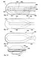
- FIG. 47illustrates insertion of an embodiment of the catheter within tissue
- FIG. 48illustrates inflation of the catheter of FIG. 47 within tissue
- FIG. 49shows yet another embodiment of the catheter within tissue
- FIG. 50depicts the catheter of FIG. 49 after inflation within tissue
- FIG. 51illustrates another embodiment of the catheter
- FIG. 52shows yet another embodiment of the catheter
- FIG. 53depicts another embodiment of the catheter.
- FIG. 54illustrates another embodiment of the catheter.
- FIG. 1is a schematic illustration of a cryosurgical system in accordance with the invention.
- the systemincludes a supply of cryogenic or cooling fluid 10 in communication with the proximal end 12 of a flexible catheter 14 .
- a fluid controller 16is interposed or in-line between the cryogenic fluid supply 10 and the catheter 14 for regulating the flow of cryogenic fluid into the catheter in response to a controller command.
- Controller commandscan include programmed instructions, sensor signals, and manual user input.
- the fluid controller 16can be programmed or configured to increase and decrease the pressure of the fluid by predetermined pressure increments over predetermined time intervals.
- the fluid controller 16can be responsive to input from a foot pedal 18 to permit flow of the cryogenic fluid into the catheter 14 .
- One or more temperature sensors 20 in electrical communication with the controller 16can be provided to regulate or terminate the flow of cryogenic fluid into the catheter 14 when a predetermined temperature at a selected point or points on or within the catheter is/are obtained.
- a temperature sensorcan be placed at a point proximate the distal end 22 of the catheter and other temperature sensors 20 can be placed at spaced intervals between the distal end of the catheter and another point that is between the distal end and the proximal end.
- the cryogenic fluidcan be in a liquid or a gas state.
- An extremely low temperaturecan be achieved within the catheter, and more particularly on the surface of the catheter by cooling the fluid to a predetermined temperature prior to its introduction into the catheter, by allowing a liquid state cryogenic fluid to boil or vaporize, or by allowing a gas state cryogenic fluid to expand.
- Exemplary liquidsinclude chlorodifluoromethane, polydimethylsiloxane, ethyl alcohol, HFC's such as AZ-20 (a 50—50 mixture of difluoromethane & pentafluoroethane sold by Allied Signal), and CFC's such as Dupont's Freon.
- Exemplary gassesinclude nitrous oxide, and carbon dioxide.
- the catheter 14includes a flexible member 24 having a thermally-transmissive region 26 and a fluid path through the flexible member to the thermally-transmissive region.
- a fluid pathis also provided from the thermally-transmissive region to a point external to the catheter, such as the proximal end 12 .
- exemplary fluid pathscan be one or more channels defined by the flexible member 24 , and/or by one or more additional flexible members that are internal to the first flexible member 24 .
- a “thermally-transmissive region”is intended to broadly encompass any structure or region of the catheter 14 that readily conducts heat.
- thermally-transmissive region 26a metal structure exposed (directly or indirectly) to the cryogenic fluid path is considered a thermally-transmissive region 26 even if an adjacent polymeric or latex catheter portion also permits heat transfer, but to a much lesser extent than the metal.
- the thermally-transmissive region 26can be viewed as a relative term to compare the heat transfer characteristics of different catheter regions or structures.
- thermally-transmissive region 26can include a single, continuous, and uninterrupted surface or structure, it can also include multiple, discrete, thermally-transmissive structures that collectively define a thermally-transmissive region that is elongate or linear. Depending on the ability of the cryogenic system, or portions thereof, to handle given thermal loads, the ablation of an elongate tissue path can be performed in a single or multiple cycle process without having to relocate the catheter one or more times or drag it across tissue. Additional details of the thermally-transmissive region 26 and the thermal transfer process are described in greater detail below.
- the thermally-transmissive region 26 of the catheter 14is deformable.
- An exemplary deformationis from a linear configuration to an arcuate configuration and is accomplished using mechanical and/or electrical devices known to those skilled in the art.
- a wall portion of the flexible member 24can include a metal braid to make the catheter torqueable for overall catheter steering and placement.
- a cord, wire or cablecan be incorporated with, or inserted into, the catheter for deformation of the thermally transmissive region 26 .
- the cryogenic system of FIG. 1is better understood with reference to its use in an operative procedure as shown in FIG. 2 .
- the catheter 14is directed through a blood vessel 30 to a region within the heart, such as an atrial or ventricular chamber, where the lesion will be made.
- the thermally-transmissive region 26is placed proximate to the tissue to be ablated.
- the thermally-transmissive region of the cathetermay be deformed to conform to the curvature of the tissue before, during, or after placement against the tissue.
- the controller 16allows or causes cryogenic fluid to flow from the cryogenic fluid supply 10 to the fluid path in the catheter 14 and thence to the thermally-transmissive region 26 to ablate the desired area or to cold map along the same tissue area.
- a first conduitis concentric within a second conduit and cooling fluid travels to a thermally-transmissive region proximate a closed distal end of the catheter through a first conduit (fluid path) and is exhausted from the catheter through the second conduit (fluid path).
- FIGS. 3, 4 , 5 , 12 - 16 and 18illustrate embodiments of the catheter, or portions thereof, having two or more thermally-transmissive segments in a spaced-apart relationship.
- Each of the illustrated cathetersincludes a closed tip 32 that can include a thermally-transmissive material.
- thermally-transmissive elements 34are integral with a distal portion of a catheter.
- Each of the thermally-transmissive elements 34includes a first side or face 36 (shown in FIGS. 12 and 13) exposed to a cryogenic fluid path and cryogenic fluid (shown by arrows) and a second side or face 38 exposed to points exterior to the catheter.
- the first side 36 and/or second side 38 of any or all of the thermally-transmissive elements 34can be substantially flush with, recessed below, or protruding from the inner surface 40 and outer surface 42 of a portion of the catheter.
- the thermally-transmissive elements 34are separated by flexible portions of material 44 than can range from slightly less thermally-transmissive than the adjacent thermally-transmissive elements to substantially less thermally-transmissive than the adjacent elements.
- the thermally-transmissive elements 34are annular, cylindrical elements which are made of gold-plated copper or bronze.
- Thermocouples 35can be associated with one or more of the elements 34 and the tip 32 .
- the thermally-transmissive elements 34can be completely exposed, embedded, or a combination thereof along the full 360° of the catheter's circumference. In certain applications the thermally-transmissive elements traverse or define less than 360 ° of the catheter's circumference as shown in FIGS. 14-16 and as described below.
- each thermally-transmissive element 34The longitudinal width of each thermally-transmissive element 34 , the spacing between elements, the material thickness, and the material composition are matched with a selected cryogenic fluid, one or more cryogenic fluid delivery locations within the catheter and fluid delivery pressure to produce overlapping cold regions which produce a linear lesion.
- the embodiment illustrated in FIG. 4is substantially identical to the embodiment of FIG. 3, however, at least one of the thermally-transmissive elements 34 includes a first open end 46 that defines a first plane and a second open end 48 that defines a second plane, wherein the first and second planes intersect to give the annular elements a wedge-like appearance.
- a configurationpermits adjacent thermally-transmissive elements 34 to be positioned very closely together, but it can limit the possibilities for deforming the thermally-transmissive region 26 , which, in this embodiment, is flexible in the direction indicated by the arrow.
- the thermally-transmissive elements 34are substantially rigid and are separated and/or joined by a flexible material 44 .
- the thermally-transmissive elements 34are flexible and are interdigitated with either rigid or flexible segments.
- a metal bellowscan have enough stiffness to retain a selected shape after a deforming or bending step.
- the distal tip 32(or a portion thereof) can be deformable.
- FIG. 6illustrates a tip 32 having thermally-transmissive, flexible, bellows 50 .
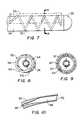
- FIG. 7illustrates a catheter embodiment having an elongate, thermally-transmissive region 26 that includes a helical coil 52 at least partially embedded in the flexible member 24 .
- a first portion 54 of the helical coil 52is exposed to a fluid path within the flexible member 24 and a second portion 56 of the helical coil is exposed to the exterior of the flexible member.
- the first portion 54 of the coilcan be substantially flush with, recessed below, or protruding from an inner surface 58 of the flexible member 24 .
- the second portion 56 of the coil 52can be substantially flush with, recessed below, or protruding from an outer surface 60 of the flexible member 24 .
- the second portion 56 of the coil 52is exposed along only a portion of the outer circumference of the flexible member 24 to define a longitudinally-elongate, thermally-transmissive region 26 .
- This configurationcan be provided by eccentrically mating the helical coil 52 to the catheter so that the longitudinal axis of the coil and the longitudinal axis of the catheter are substantially parallel.
- the eccentric positioning of the coil 52provides excellent cooling performance because the surface area available for thermal exchange between the first portion 54 of coil and the cryogenic fluid is greater than the surface area available for thermal exchange between the second portion 56 of the coil and adjacent tissue where cooling power is delivered by each exposed coil portion to provide a linear lesion.
- FIG. 9an alternative embodiment is shown wherein a first portion 62 of the coil 52 is exposed around the entire circumference of the flexible member 24 , and a second portion 64 is exposed to a fluid path around the inner surface of the flexible member 24 . This is achieved by having the longitudinal axis of the helical coil 52 co-axial with the longitudinal axis of the catheter.
- the coil 52is solid. However, in other embodiments the coil can be an elongate, hollow, gas expansion chamber.
- FIG. 10illustrates a portion of a helical coil 52 that includes a passage that defines at least a portion of a fluid path through a flexible member of the catheter.
- the coil 52defines a first fluid path diameter at a fluid entry point 66 and a second fluid path diameter that is greater than the first fluid path diameter at a gas expansion or boiling location 68 .
- Gas escaping from a fluid exit point 70can be exhausted through an open central region of the coil and/or another passage through the flexible member 24 .
- FIG. 11illustrates an embodiment of the catheter wherein a continuous, elongate, thermally-transmissive strip 72 is longitudinally integrated with a flexible member 24 .
- the stripcan include a bellows-like structure. As described above with respect to other embodiments, a first portion of the strip can be substantially flush with, recessed below, or protrude from the outer surface of the flexible member. Similarly, a second portion of the strip can be substantially flush with, recessed below, or protrude from an inner surface of the flexible member.
- FIG. 12an embodiment of the catheter is illustrated having a second or inner flexible member 74 within a lumen of first or outer flexible member 24 , wherein the second flexible member defines a fluid path to the thermally-transmissive region 26 .
- the inner member 74can include a single opening 76 at or near the tip 32 . Cryogenic fluid is expelled from the opening 76 and returns to the proximal end of the catheter along a fluid path defined by the outer wall of the inner member 74 and the inner wall of the outer member 24 .
- This fluid path configurationis also partially illustrated in FIGS. 8, 9 , and 13 .
- FIG. 8 9 , and 13Alternatively, as also shown in FIG.
- the inner member 74can be provided with multiple openings 78 proximate to and/or aligned with the inner face of one or more thermally-transmissive elements 34 to achieve more uniform cooling across the entire elongate, thermally-transmissive region 26 .
- thermally-transmissive elements 34are arcuate and form complete and continuous 360 degree structures that traverse the complete circumference of the catheter, notwithstanding being flush with, depressed below, or raised above the outermost surface of the flexible member 24 .
- the arcuate elements 34 ′, 34 ′′, and 34 ′′′ illustrated in FIGS. 14-16respectively, traverse less than 360 degrees of the circumference of the first flexible member and do not form complete loops.
- element 34 ′defines an approximately 270 degree arc.
- the thermally-transmissive element 34 ′′defines an approximately 180 degree arc; and in FIG.
- the thermally-transmissive element 34 ′′′defines an approximately 90 degree arc.
- a cathetercan include combinations of element types, such as a complete ring or loop element, a 270 degree element and a 180 degree element as desired to define a thermally transmissive region.
- the bellows-like elementscan also be less than 360 degrees.
- the less than 360 degree arcuate elementsprovide unique functional benefits with respect to thermal transfer and flexibility of the thermally-transmissive region.
- the portion of the catheter between the opposing ends of element 34 ′, 34 ′′, 34 ′′′does not include a rigid structure, but rather only the resilient material of flexible member 24 , the thermally-transmissive region of the catheter can be more tightly curved (gap between ends inward and element facing outward) than it could with complete 360 degree structures, especially if the elements are relatively long longitudinally.
- the inner member 74can be adapted to direct cooling fluid at only the thermally transmissive element(s) and the shape and/or the number of openings for cooling fluid can be configured differently depending on the length of the arc defined by the thermally-transmissive element(s).
- FIG. 14illustrates an embodiment of the inner member having three openings opposing the thermally transmissive element 34 ′;
- FIG. 15illustrates two openings for a smaller arc; and
- FIG. 16discloses a single opening for an even smaller arc.
- a similar effectcan also be achieved by providing a non-circular 360 degree element or by eccentrically mounting a circular 360 degree element with respect to the flexible member, wherein a portion of the 360 degree element is embedded within the wall of the flexible member or otherwise insulated from the cryogenic fluid path in a manner similar to that shown in FIG. 8 .
- thermal transfer pins 80protruding from the inner face of a thermally-transmissive element 34 .
- the pinspermit thermal transfer through the flexible member 24 .
- the pinsare equally suitable for complete 360 degree element structures or less than 360 degree structures. Although only pins are shown on any geometric or surface means to increase heat transfer including but not limited to pins, irregularities, channels or surface modifications may be used.
- FIG. 18yet another embodiment of the catheter is shown wherein rigid metal rings 34 a-c are interdigitated with flexible segments 44 a-c to define a first flexible member and a thermally-transmissive region approximately one inch in length.
- a second flexible memberis concentric within the first flexible member and has an outlet for cryogenic fluid at its distal end.
- Thermocouples 82 a-ccan be associated with one or more of the rings 34 a-c.
- the thermal loading of a cooling systemcan be reduced by providing thermally-transmissive elements that span less than 360 degrees.
- the thermal loadingcan also be reduced by sequentially cooling the thermally-transmissive region.
- One way to sequentially coolis to modulate the pressure of the cooling fluid along the fluid path through the flexible member. This modulation can be performed by the fluid controller which can be programmed to increase and decrease the pressure of the fluid by predetermined pressure increments over predetermined time intervals.
- the cryogenic fluidis a liquid that provides cooling by changing phase from liquid to gas
- the change of pressurealters the physical location along the fluid path where the phase change takes place and concomitantly changes the point of coldest temperature along the thermally-transmissive region.
- varying the pressure of the fluidcan provide a moving ice-formation “front” along the catheter, enabling the creation of a linear lesion.
- a method of forming an elongate tissue lesioncan include the following steps using any of the above described catheters having an elongate, thermally-transmissive region.
- a cryogenic fluidis introduced into the flexible member at a first predetermined pressure.
- the pressure of the cryogenic fluidis incrementally increased within the flexible member until a second predetermined pressure is achieved.
- the pressure of the cryogenic fluid within the flexible membercan be decreased incrementally from the second predetermined pressure to the first predetermined pressure, wherein the steps of incrementally increasing and decreasing the pressure define a thermal cycle.
- from one to eight thermal cyclesare required to achieve a desired therapeutic effect.
- about ten increments of about five seconds in durationare selected and pressure is increased by about 20 to 40 pounds per square inch in each increment.
- an elongate lesioncan be created in less than 20 minutes.
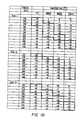
- FIG. 19is a table that illustrates sequential cooling in a catheter as described above having a thermally-transmissive region that includes a tip and three elements or rings.
- the tableillustrates three tests conducted in a still bath at 37° C., using AZ-20 as the cryogenic fluid. Associated with each pressure increment are measured temperatures at the tip, first ring, second ring, and third ring.
- the shaded regionillustrates the sequential movement of a target temperature range (upper ⁇ 40's to low ⁇ 50's) in response to a change in pressure. Although values are only provided for three rings, a similar effect and pattern is obtained with more than three rings or elements.
- thermally-transmissive portion of another embodiment of a medical device or structure such as a catheteris illustrated in a sectional view.
- the structurecan include an inner passage or lumen as described above with respect to other embodiments, but which is not shown in this illustration for purposes of clarity.
- the illustrated portionis the outer passage or lumen that defines an elongate ablation region.
- Thermally-transmissive elements 84such as gold plated copper, are joined to adjacent elements by resilient connecting elements 86 , such as a stainless steel springs welded to the ends of the elements 84 .
- a resilient bio-compatible material 88covers the connecting elements 86 and the interstices between adjacent thermally-transmissive elements.
- the material 88is vulcanized silicone. It should be noted in the illustration that the surface of the elements 84 is contiguous and co-planar with the material 88 to provide a smooth outer surface.
- FIG. 21illustrates a single thermally-transmissive element 84 having reduced diameter ends 90 and 92 .
- the wider central portion 94provides an expansion chamber for gas (shown by arrows) exiting an apertured inner passage 96 .
- FIG. 22shows additional detail of the end 90 of the element 84 .
- the end 90is textured, such as by providing serrations 98 , to provide a good adhesion surface for the material 88 .
- FIG. 23a thermally-transmissive portion of yet another embodiment of a flexible cryogenic structure is illustrated in a sectional view.
- an inner, apertured structure 100has a flat wire 102 wrapped around it in a spiral manner.
- Thermally-transmissive segments 104are disposed upon the wire 102 in a spaced-apart relationship, and a flexible, bio-compatible material 106 fills the interstices between segments 104 .
- a thermocouple 108can be associated with each segment 104 .
- a wire 109connects the thermocouple 108 to instrumentation near the proximal end of the structure.
- the exterior surface of the structureis smooth, and the structure can include 3 to 12 segments 104 .
- the inner structure 100is made of PTFE, the material 106 is 33 D Pebax, and the wire 102 is stainless steel or Nitinol.
- An apertured inner passage(similar to that shown in FIG. 21) is placed within the structure.
- FIG. 24illustrates still another embodiment of a cryogenic cooling structure that includes a surface or wall 110 including a polymer or elastomer that is thin enough to permit thermal transfer.
- a polymer or elastomerthat is thin enough to permit thermal transfer.
- polyamide, PET, or PTFEhaving a thickness of a typical angioplasty balloon or less (below 0.006 inches) provides acceptable thermal transfer.
- the thinness of the wall 110allows it to readily collapse or otherwise deform under vacuum or near vacuum conditions applied to evacuate fluid/gas from the structure.
- the structureis provided with one or more supporting elements 112 such as a spring.
- the cooling structureis illustrated in association with a catheter 114 having a closed distal tip 116 and mono or bipolar ECG rings 118 , 120 , 122 .
- the thermally-transmissive regionis approximately 30 mm in length and is effective for thermal transfer over its entire circumference. However, as illustrated in FIG. 11, the thermally-transmissive region can be confined to specific region(s
- an embodiment of the catheteris illustrated having three flexible members or injection tubes 210 , 211 and 212 disposed within a first or outer flexible member 200 .
- the inner flexible members 210 , 211 and 212are arranged in a staggered configuration within the outer flexible member 200 .
- staggeredmay be used to designate both a linearly/axially staggered configuration or alternatively, a rotationally staggered configuration.
- the flexible members 210 , 211 and 212thus define multiple staggered fluid paths within the outer member 200 .
- thermocouples 204 disposed along the outer surface of the outer flexible member 200may be integrated with an internal feedback loop to provide independent and variable regulation of these freeze zones.
- the first inner member 210includes at least one opening 214 positioned proximate an electrode ring member 207 . Cryogenic fluid is expelled from the opening 214 and returns to the proximal end of the catheter along a fluid path defined by the inner wall 218 of the outer member 200 , as shown in FIG. 26 .
- the second inner member 211includes at least one opening 215 positioned proximate a second electrode ring member 208 . Cryogenic fluid is also expelled from the opening 215 and returns to the proximal end of the catheter along the fluid path defined by the inner wall 218 of the outer member 200 .
- the third inner member 212includes at least one opening 216 positioned proximate a third electrode ring member 209 .
- the cathetercan be provided with only two inner members, or four or more inner members, not shown, disposed within the outer member.
- the inner memberswould have one or more openings proximate to and/or aligned with the inner face of one or more transmissive elements, as described earlier herein, to achieve different regions of freeze zones across the entire elongate member.
- all the staggered inner membersmay be simultaneously provided with cryogenic fluid to create a linear lesion for selected applications.
- the flow of cooling fluid along the fluid paths through the flexible memberscan also be alternated in any number of patterns among the multiple inner members to provide a desired cooling pattern such as a discontinuous or a continuous lesion across the entire catheter.
- a catheter with a plurality of thermally conductive electrode ringswould have an underlying injection tube or tubes controlling the release of cryogenic fluid to each electrode.
- a cathetercould be placed in the coronary sinus or endocardially along the atrioventricular junction.
- an electrogram of interestis located using a specific electrode ring on the catheter.
- Coldmappingmay be performed on the selected location to confirm the correctness of the location. Once, confirmed, the area is cryoablated using the same electrode ring.
- the same embodiments and others described hereinare equally suited to other organs besides the heart and/or any body portion that would benefit from the application of thermal energy.
- an embodiment of the catheteris illustrated having an outer member 220 with a fixed injection tube 230 disposed within a slidable sheath or overtube 240 therein.
- the injection tube and overtubeare shown spaced apart for illustrative purposes only.
- the injection tubeis sized so that an outer surface of the injection tube engages an inner surface of the overtube while still allowing one member to slide or rotate relative to the other.
- the fixed injection tube 230has multiple openings 232 , 234 formed thereon and the slidable overtube also has multiple openings or ports 242 , 244 formed thereon.
- opening 232 on the injection tube 230coincides or is aligned with opening 242 on the slidable overtube 240 .
- any fluid exiting the injection tube 230 from opening 232is able to escape through opening 242 .
- opening 232is covered or blocked by the surface of overtube 240 as now shown in FIG. 28 .
- opening 234 of injection tube 230is aligned with opening 244 of overtube 240 .
- opening 242is not aligned with any opening formed on the surface of injection tube 230 .
- the slidable overtubeis positionable in any number of positions relative to the fixed injection tube.
- the overtubemay also be used to partially cover the openings on the injection tube to provide for a limited or controlled flow of cryogenic fluid.
- cryogenic fluidis expelled from the opening and returns to the proximal end of the catheter along a fluid path defined by the inner wall 226 of the outer member 220 .
- the non-aligned openingwill not expel fluid since the opening will be blocked.
- the injection tube and overtubecan be provided with three or more openings to achieve multiple cooling/freeze zones along the length of the catheter.
- an embodiment of the catheteris illustrated having a slidable injection tube 260 disposed within a fixed sheath or overtube 270 .
- both the injection tube 260 and overtube 270are disposed within a flexible outer member 250 .
- the slidable injection tube 260has multiple openings 262 , 264 formed thereon which allows for the release of cryogenic fluid.
- the fixed overtube 270also has multiple perforations or openings 272 , 274 formed thereon which allows for the differential release of fluid as described in more detail below.
- the injection tubemay be further provided with a thermistor 254 disposed proximate the distal end of the tube to provide thermistor feedback.
- the openingscan be controlled by miniaturized means such as micro or nanovalves.
- opening 262 of the injection tube 260coincides or is aligned with opening 274 of the fixed overtube 270 .
- opening 262is then aligned with corresponding opening 272 on the overtube 270 in FIG. 32 .
- openings 262 , 264 of injection tube 260are aligned with openings 272 , 274 of overtube 270 .
- the injection tube 260is positionable in any number of locations relative to the fixed overtube 270 .
- cryogenic fluidis expelled from the openings and returns to the proximal end of the catheter along a fluid path defined by an inner wall 256 of the outer member 250 .
- the injection tube 260 and overtube 270can be provided with multiple openings proximate to and/or aligned with the inner face of one or more thermally-transmissive elements as described earlier herein to achieve more uniform cooling across the entire elongate, thermally-transmissive region.
- an embodiment of the catheteris illustrated having an outer member 280 with an injection tube 290 with multiple opposed openings 292 - 297 formed therein.
- Either the injection tube 290 or the overtube 300may be slidable in a longitudinal plane to expose and/or cover one or more of the opposed openings on the injection tube 290 .
- openings 294 , 295 formed on the injection tube 290are aligned with openings 302 , 303 formed on the overtube 230 .
- the injection tubemay be positioned in a forwardmost position, not shown, to expose openings on the injection tube proximate the tip of the catheter. In this configuration, the injection tube would provide fluid to cool the area around the tip of the catheter.
- electrode rings as shown in FIG. 25may be provided along the outer surface of any of the outer members.
- the electrodeswould serve both as electrical conductors and as a thermal transmitter at each location.
- the catheterhaving one or more rotatable members disposed within a flexible outer member 310 .
- the catheterincludes an overtube member 312 and an injection tube member 314 , one or both of which are rotatable with respect to one another.
- the injection tube 314is rotatable relative to the fixed overtube 312 .
- the injection tube 314may be rotatable in either or both a clockwise and counterclockwise direction as indicated by arrows 320 and 322 .
- opening 316 formed on the overtube 312aligns with an opening 318 formed on the injection tube 314 .
- the opening 318 on the injection tube 314is placed out of alignment with the opening 316 formed on overtube 312 , as shown in FIG. 37 .
- the injection tube 314may be fixed in the catheter while the overtube 312 is rotatable.
- both the injection tube and overtubemay both be rotatable.
- the injection tube and/or the overtubeare rotatable and slidable within the outer member.
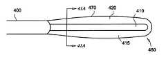
- a catheteris shown generally as 460 and comprises a pliant outer member 470 , a fluid transport member 410 and a catheter body 400 .
- a chamber 420is formed between the outer member 470 and the fluid transport member 410 .
- the chamber 420is filled with a bio-compatible fluid 415 that insulates a tissue 450 from the thermal energy present in the fluid transport member 410 when a thermally active fluid is circulated therein.
- the catheter 460is located within the tissue 450 to be treated as is known in the art using suitable devices such as an electrocardiogram (ECG), fluoroscope or other suitable imaging or locating device and technique.
- ECGelectrocardiogram
- fluoroscopefluoroscope
- the fluid transport member 410is brought closer to the outer member 470 . This is accomplished either by moving the fluid transport member 410 directly or by forcing the pliant outer member 470 against the fluid transport member 410 , or even using a combination of the two motions.
- Various treatmentsare possible using the above device and method such as, but not limited to, ablations and temporary interruptions of the tissue activity such as cold-mapping of the electrical activity and pathways of cardiac tissue.
- the bio-compatible fluid 415could be a viscous fluid, gel, thin liquid, or gas.
- the insulative properties of the fluid 415are selected to accommodate the desired temperature regime of the medical procedure to be performed.
- FIGS. 42 and 43illustrate another embodiment of the catheter shown generally as 560 and comprises a catheter body 515 , a thermally transmissive region 500 , a chamber 510 , a fluid transport member 520 and a gap 512 .
- the gap 512is selected to provide a path to conduct the thermal energy contained within the fluid transport member 520 to the thermally transmissive region 500 .
- the catheter 560is located proximal to the selected tissue 525 .
- the fluid transport member 520is aligned with the tissue 525 .
- the catheter body 515may be rotated to position the fluid transport member 520 .
- a thermally energetic fluidis circulated within the fluid transport member 520 and the thermal energy contained therein is transferred through the thermally transmissive region 500 to the selected tissue 525 .
- the gap 512may be fixed, it is within the scope of this embodiment to vary the gap 512 using mechanical means such as a control wire (not shown) or other suitable lumen positioning means as is known in the art.
- An insulating fluid or materialmay fill the chamber 510 to provide further protection to non-targeted tissue surrounding the catheter 560 .
- the chamber 510may also be used to house sensors such as thermocouples, ECG electrodes, etc. (not shown) to further aid in locating and providing data regarding the tissue in contact with the catheter 560 .
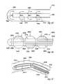
- a catheter 1450comprising an expandable outer member 1400 , a fluid transport member 1410 and a body 1420 .
- the outer member 1400is expanded and retracted using a chamber inflation member 1415 .
- the diameter of a thermally transmissive region 1445is generally close to the diameter of the catheter body 1420 .
- a bio-compatible fluidis injected into a chamber 1455 created between the outer member 1400 and the fluid transport member 1410 using the chamber inflation member 1415 .
- the fluid transport member 1410is flexible and movable towards the thermally transmissive region 1445 .
- a guide wire (not shown) or other suitable method of moving the fluid transport member 1410 such as using a memory material to deform the fluid transport member 1410 to a position 1435is used to transfer the thermal energy contained in the fluid transport member 1410 to the thermally transmissive region 1445 which is in contact with the selected tissue (not shown).
- the fluid transport member 1410is moved back to a neutral position and the chamber 1455 is deflated by removing fluid from the chamber 1455 using the chamber inflation member 1415 .
- a multiple treatment zone catheter 2700comprising a plurality of thermally transmissive regions 2400 , a plurality of outer members 2445 , a body 2420 and a plurality of fluid transport members 2410 . Additionally, sensors 2550 are utilized to help locate the catheter 2700 and to provide data such as the temperature of the catheter 2700 or tissue contacting the catheter 2700 .
- Each of the outer members 2445are inflatable between an expanded position and a deflated position 2710 .
- Each of fluid transport members 2410are movable between a neutral position and a deflected position 2720 . When the fluid transport member 2410 is positioned adjacent to the thermally transmissive region 2400 , energy is transferred to the tissue in proximity to the region 2400 .
- the multiple treatment zone catheter 2700is flexible to enable the thermally transmissive regions to be advantageously positioned within the selected tissue (as shown in FIGS. 47 and 48 ).
- FIGS. 47 and 48illustrate the method of using the multiple treatment zone catheter 2700 within the tissue 1600 .
- Treatment sites 1610are selected and the catheter 2700 is positioned to line up the thermally transmissive regions 2400 with the selected sites 1610 .
- the treatment sites 1610are not smooth (as shown in FIG. 47 ).
- the sites 1610are smoothed (as shown in FIG. 48) and made more amenable to treatment.
- Each fluid transport member 2410is moved into position adjacent to the thermally transmissive regions 2400 .
- a thermally energetic fluidis then circulated within the fluid transport members 2410 for an amount of time selected to perform a medical procedure such as ablation, etc.
- the fluid transport members 2410may be repositioned without moving the rest of the catheter 2700 to perform further treatments.
- the outer members 2445are then deflated and the catheter 2700 is repositioned or removed depending on the procedure.
- a catheter 1450 having a single treatment regionis shown in operation. Again, in a similar manner as discussed above, the catheter 1450 is inserted in the tissue 1600 . The uneven surface of the tissue 1600 is smoothed and stretched by expanding the outer member 1620 against the tissue 1600 . The fluid transport member 1410 is moved towards the treatment site 1610 and thermal energy is transferred to the tissue 1600 proximal to the treatment site 1610 . As discussed above with respect to the multiple treatment zone catheter 2700 , the catheter 1450 is removed or repositioned or the fluid transport member 1410 is repositioned for further treatments.
- a sliding treatment catheter 1805is shown as comprising a body 1800 , a thermally transmissive region 1810 , a fluid transport member 1830 , a support slide 1820 , a support cap 1815 , and a sliding contact 1840 .
- the fluid transport member 1830is deformable and moves towards or away from the thermally transmission region 1810 when the sliding contact 1840 is moved.
- a wire 1845is used to move sliding contact 1840 (or any other means of applying a linear force to the sliding contact 1840 ).
- a chamber 1855may be formed between the thermally transmissive region 1810 and the fluid transport member 1830 .
- the chamber 1855is filled with an insulative bio-compatible fluid to isolate non-selected tissue from the thermal energy contained within the fluid transport member 1830 .
- Sensorssuch as thermocouples and ECG electrodes (not shown) may be located within the chamber or on the surface of the thermally transmissive region 1810 or body 1800 to provide information to an operator.
- the catheter 1805may include a rotatable fluid transport member 1830 .
- the sliding contact 1840is also able to rotate around the support slide either in tandem with or independently of the support cap 1815 .
- This embodimentallows treatment to occur anywhere within the circumference of the thermally transmissive region 1810 without repositioning the entire catheter 1805 .
- linear treatment patternsare selected by rotating both the support cap 1815 and the sliding contact 1830 in tandem, and curved treatment patterns are selected by holding either the sliding contact 1840 or the support cap 1815 stationary while rotating the other or by counter rotating the sliding contact 1840 and the support cap 1815 .
- a catheter 1900is illustrated as comprising a body 1905 , a thermally transmissive region 1915 and a movable fluid transport member 1910 .
- This embodimentis similar to the catheter shown in FIG. 44, however, the catheter 1900 utilizes a constant diameter thermally transmissive region 1915 instead of an inflatable region as shown in FIG. 44 . Because the thermally transmissive region 1915 does not inflate, the thermally transmissive region 1915 must be placed in proximity to the selected tissue to begin the process. After positioning the thermally transmissive region 1915 in proximity to the selected tissue, the fluid transport member 1910 is moved proximally to the thermally transmissive region 1915 and thermal energy is applied to the target tissue (not shown) to perform the treatment.
- FIG. 53Another embodiment of a catheter, shown generally as 1965 in FIG. 53, comprises a body 1960 , a thermally transmissive region 1955 and a rotatable fluid member 1950 .
- the fluid transport member 1950is rotated to align the portion of fluid transport member 1950 adjacent to the interior surface of the thermally transmissive region 1955 with the selected treatment site (not shown).
- a thermally active fluidis circulated within the fluid transport member 1950 for a medically effective period of time based on the desired procedure. After the required transfer of thermal energy to the selected site, the fluid transport member 1950 may be rotated to a new position and the process repeated or the catheter 1965 may be removed.
- FIG. 54A further embodiment is illustrated in FIG. 54 showing a catheter 2000 as comprising a body 2002 , an outer member 2010 , a movable fluid transport member 2020 and a thermally transmissive region 2030 .
- the fluid transport member 2020is flexible and is placed proximal to the outer member 2010 when the outer member 2010 is inflated.
- the fluid transport member 2020is also rotatable to provide treatment zones all along the thermally transmission region 2010 without repositioning the entire catheter 2000 or rotating the body 2002 .
- the slidable and rotatable inner and outer tubesmay have openings so arranged as to allow the fluid releasing openings to be in a variety of open and closed configurations with a minimum of relational movement between the tubes.
- an outer member 330has disposed therein one slidably disposed inner tube 336 which has openings 338 formed thereon in a constant sequence, and a matching slidably disposed outer tube 332 which has openings 334 formed thereon in a constant sequence of slightly different length or intervals.
- small linear relational movementsbring the openings on the outer tube 332 and the inner tube 336 into an overlapping configuration.
- openings as shown and described hereinmay be so shaped as to allow additional control of fluid release.
- an outer holecould be tear-shaped and match up with an inner opening that is tear-shaped rotationally aligned 180° oppositely not shown. As the two narrow ends begin to overlap with slidable motion, a tiny aperture is created. With further slidable motion in the same direction, larger areas of the two openings overlap and larger volumes of cryogenic fluid can be released.
- a typical fluid transport member 1500is illustrated in FIG. 45 .
- the fluid transport membershown generally as 1410 , allows an energetic fluid 1530 to be circulated within an outer wall 1502 .
- a conduit 1500injects the fluid 1530 into the space formed between the wall 1502 and the conduit 1500 .
- a series of holes 1510 or a conduit end opening 1520 or a combination of bothmay be used to direct the fluid 1530 within the fluid transport member 1410 .
- the conduitmay be flexible or rigid depending on the required use.
- the wall 1502is also flexible or rigid to complement the conduit 1500 and required use.
- fluid transport member 1410examples include a solid thermally transmissive conduit 1500 where the energetic fluid transfer of energy takes place before reaching the end of the fluid transport member 1410 .
- the entire end of the transport member 1410is a thermally transmissive solid which is thermally activated prior to reaching the end and the energy is transmitted along the fluid transport member 1410 without actually circulating the fluid 1530 at the end therein.
- the devices as shownare not to be limited to catheters but should be viewed more broadly as cryogenic structures or portions thereof. It is therefore understood that, within the scope of the appended claims, the present invention may be practiced otherwise than as specifically described hereinabove. All references cited herein are expressly incorporated by reference in their entirety.
Landscapes
- Health & Medical Sciences (AREA)
- Life Sciences & Earth Sciences (AREA)
- Surgery (AREA)
- Public Health (AREA)
- General Health & Medical Sciences (AREA)
- Engineering & Computer Science (AREA)
- Biomedical Technology (AREA)
- Heart & Thoracic Surgery (AREA)
- Veterinary Medicine (AREA)
- Nuclear Medicine, Radiotherapy & Molecular Imaging (AREA)
- Animal Behavior & Ethology (AREA)
- Biophysics (AREA)
- Molecular Biology (AREA)
- Medical Informatics (AREA)
- Otolaryngology (AREA)
- Pulmonology (AREA)
- Anesthesiology (AREA)
- Hematology (AREA)
- Surgical Instruments (AREA)
- Media Introduction/Drainage Providing Device (AREA)
- Separation By Low-Temperature Treatments (AREA)
- Glass Compositions (AREA)
- Liquid Crystal Substances (AREA)
- Processes Of Treating Macromolecular Substances (AREA)
Abstract
Description
Claims (33)
Priority Applications (10)
| Application Number | Priority Date | Filing Date | Title |
|---|---|---|---|
| US10/016,190US6602247B2 (en) | 1997-02-27 | 2002-03-12 | Apparatus and method for performing a treatment on a selected tissue region |
| AT03743964TATE422340T1 (en) | 2002-03-12 | 2003-03-10 | CRYOGENIC DEVICE |
| CA002478086ACA2478086C (en) | 2002-03-12 | 2003-03-10 | Cryogenic apparatus |
| EP08011501AEP1967153B1 (en) | 2002-03-12 | 2003-03-10 | Cryogenic apparatus |
| PCT/IB2003/000997WO2003075776A1 (en) | 2002-03-12 | 2003-03-10 | Cryogenic apparatus |
| AT08011501TATE486536T1 (en) | 2002-03-12 | 2003-03-10 | CRYOGENIC DEVICE |
| EP03743964AEP1494603B1 (en) | 2002-03-12 | 2003-03-10 | Cryogenic apparatus |
| AU2003209593AAU2003209593A1 (en) | 2002-03-12 | 2003-03-10 | Cryogenic apparatus |
| DE60326132TDE60326132D1 (en) | 2002-03-12 | 2003-03-10 | KRYOGENE DEVICE |
| DE60334865TDE60334865D1 (en) | 2002-03-12 | 2003-03-10 | Cryogenic device |
Applications Claiming Priority (5)
| Application Number | Priority Date | Filing Date | Title |
|---|---|---|---|
| US08/807,382US5899898A (en) | 1997-02-27 | 1997-02-27 | Cryosurgical linear ablation |
| US08/893,825US5899899A (en) | 1997-02-27 | 1997-07-11 | Cryosurgical linear ablation structure |
| US09/201,071US6235019B1 (en) | 1997-02-27 | 1998-11-30 | Cryosurgical catheter |
| US09/850,668US6540740B2 (en) | 1997-02-27 | 2001-05-07 | Cryosurgical catheter |
| US10/016,190US6602247B2 (en) | 1997-02-27 | 2002-03-12 | Apparatus and method for performing a treatment on a selected tissue region |
Related Parent Applications (1)
| Application Number | Title | Priority Date | Filing Date |
|---|---|---|---|
| US09/850,668Continuation-In-PartUS6540740B2 (en) | 1997-02-27 | 2001-05-07 | Cryosurgical catheter |
Publications (2)
| Publication Number | Publication Date |
|---|---|
| US20020099364A1 US20020099364A1 (en) | 2002-07-25 |
| US6602247B2true US6602247B2 (en) | 2003-08-05 |
Family
ID=27803565
Family Applications (1)
| Application Number | Title | Priority Date | Filing Date |
|---|---|---|---|
| US10/016,190Expired - LifetimeUS6602247B2 (en) | 1997-02-27 | 2002-03-12 | Apparatus and method for performing a treatment on a selected tissue region |
Country Status (7)
| Country | Link |
|---|---|
| US (1) | US6602247B2 (en) |
| EP (2) | EP1494603B1 (en) |
| AT (2) | ATE486536T1 (en) |
| AU (1) | AU2003209593A1 (en) |
| CA (1) | CA2478086C (en) |
| DE (2) | DE60334865D1 (en) |
| WO (1) | WO2003075776A1 (en) |
Cited By (51)
| Publication number | Priority date | Publication date | Assignee | Title |
|---|---|---|---|---|
| US20030220634A1 (en)* | 2000-08-09 | 2003-11-27 | Ryba Eric L. | Refrigeration source for a cryoablation catheter |
| US20040024413A1 (en)* | 2002-07-31 | 2004-02-05 | Lentz David J. | Wire reinforced articulation segment |
| US20040034344A1 (en)* | 2002-08-16 | 2004-02-19 | Eric Ryba | Tip pressure monitoring for cryoablation catheters |
| US20040034345A1 (en)* | 2002-08-16 | 2004-02-19 | Lentz David J. | Heat transfer segment for a cryoablation catheter |
| US20040034365A1 (en)* | 2002-08-16 | 2004-02-19 | Lentz David J. | Catheter having articulation system |
| US20040116921A1 (en)* | 2002-12-11 | 2004-06-17 | Marshall Sherman | Cold tip rf/ultrasonic ablation catheter |
| US20040116917A1 (en)* | 2002-12-11 | 2004-06-17 | Lentz David J. | System and method for performing a single step cryoablation |
| US20040116916A1 (en)* | 2002-12-11 | 2004-06-17 | Lentz David J. | Coaxial catheter system for performing a single step cryoablation |
| US6824543B2 (en) | 2002-12-11 | 2004-11-30 | Cryocor, Inc. | Guidance system for a cryocatheter |
| US20040243118A1 (en)* | 2001-06-01 | 2004-12-02 | Ayers Gregory M. | Device and method for positioning a catheter tip for creating a cryogenic lesion |
| US20050016188A1 (en)* | 2003-07-24 | 2005-01-27 | Lentz David J. | Distal end for cryoablation catheters |
| US20050027289A1 (en)* | 2003-07-31 | 2005-02-03 | Thomas Castellano | Cryoablation systems and methods |
| US20050043724A1 (en)* | 2003-08-22 | 2005-02-24 | Eric Ryba | Reshapeable tip for a cryoprobe |
| US20050059963A1 (en)* | 2003-09-12 | 2005-03-17 | Scimed Life Systems, Inc. | Systems and method for creating transmural lesions |
| US20050177146A1 (en)* | 2004-02-10 | 2005-08-11 | Marshall Sherman | System and method for assessing ice ball formation during a cryoablation procedure |
| US20050198972A1 (en)* | 2004-03-10 | 2005-09-15 | Lentz David J. | Pressure-temperature control for a cryoablation catheter system |
| US20050283146A1 (en)* | 2004-06-17 | 2005-12-22 | Lentz David J | Thermally extended spiral cryotip for a cryoablation catheter |
| US20060069385A1 (en)* | 2004-09-28 | 2006-03-30 | Scimed Life Systems, Inc. | Methods and apparatus for tissue cryotherapy |
| US7195625B2 (en) | 2002-12-11 | 2007-03-27 | Cryocor, Inc. | Catheter system for performing a single step cryoablation |
| US20080300584A1 (en)* | 2007-06-01 | 2008-12-04 | Lentz David J | Cryoablation segment for creating linear lesions |
| US7470272B2 (en) | 1997-07-18 | 2008-12-30 | Medtronic, Inc. | Device and method for ablating tissue |
| WO2009112269A2 (en) | 2008-03-12 | 2009-09-17 | Afreeze Gmbh | Ablation system |
| US20090281533A1 (en)* | 2008-05-12 | 2009-11-12 | Boston Scientific Scimed, Inc. | Apparatus and method for chilling cryo-ablation coolant and resulting cryo-ablation system |
| US20090287202A1 (en)* | 2008-05-15 | 2009-11-19 | Boston Scientific Scimed, Inc. | Apparatus and methods for cryogenically ablating tissue and adjusting cryogenic ablation regions |
| US20100241114A1 (en)* | 2009-03-20 | 2010-09-23 | Salvatore Privitera | Cryogenic probe |
| US20100319360A1 (en)* | 2009-06-23 | 2010-12-23 | Niedbala R Sam | Devices and methods for dispensing a cryogenic fluid |
| US20110009694A1 (en)* | 2009-07-10 | 2011-01-13 | Schultz Eric E | Hand-held minimally dimensioned diagnostic device having integrated distal end visualization |
| US8133199B2 (en) | 2008-08-27 | 2012-03-13 | Boston Scientific Scimed, Inc. | Electroactive polymer activation system for a medical device |
| WO2012058160A1 (en)* | 2010-10-26 | 2012-05-03 | Medtronic Ardian Luxembourg S.A.R.L. | Neuromodultion cryotherapeutic devices and associated systems and methods |
| WO2013007831A1 (en) | 2011-07-14 | 2013-01-17 | Afreeze Gmbh | Ablation applicator with a matrix filled with particles |
| US20140074081A1 (en)* | 2011-02-01 | 2014-03-13 | Channel Medsystems, Inc. | Cyrogenic treatment systems |
| US20140088584A1 (en)* | 2012-09-26 | 2014-03-27 | Boston Scientific Scimed, Inc. | Medical device balloon catheter |
| US9017317B2 (en) | 2012-12-06 | 2015-04-28 | Medtronic Ardian Luxembourg S.A.R.L. | Refrigerant supply system for cryotherapy including refrigerant recompression and associated devices, systems, and methods |
| US20150119868A1 (en)* | 2013-10-30 | 2015-04-30 | Medtronic Cryocath Lp | Feedback system for cryoablation of cardiac tissue |
| US9060754B2 (en) | 2010-10-26 | 2015-06-23 | Medtronic Ardian Luxembourg S.A.R.L. | Neuromodulation cryotherapeutic devices and associated systems and methods |
| US20150196740A1 (en)* | 2014-01-14 | 2015-07-16 | Medtronic Cryocath Lp | Balloon catheter with fluid injection elements |
| US9095321B2 (en) | 2012-11-21 | 2015-08-04 | Medtronic Ardian Luxembourg S.A.R.L. | Cryotherapeutic devices having integral multi-helical balloons and methods of making the same |
| US9241752B2 (en) | 2012-04-27 | 2016-01-26 | Medtronic Ardian Luxembourg S.A.R.L. | Shafts with pressure relief in cryotherapeutic catheters and associated devices, systems, and methods |
| US9370295B2 (en) | 2014-01-13 | 2016-06-21 | Trice Medical, Inc. | Fully integrated, disposable tissue visualization device |
| US10004550B2 (en) | 2010-08-05 | 2018-06-26 | Medtronic Ardian Luxembourg S.A.R.L. | Cryoablation apparatuses, systems, and methods for renal neuromodulation |
| US10045686B2 (en) | 2008-11-12 | 2018-08-14 | Trice Medical, Inc. | Tissue visualization and modification device |
| US10076384B2 (en) | 2013-03-08 | 2018-09-18 | Symple Surgical, Inc. | Balloon catheter apparatus with microwave emitter |
| US10342579B2 (en) | 2014-01-13 | 2019-07-09 | Trice Medical, Inc. | Fully integrated, disposable tissue visualization device |
| US10405886B2 (en) | 2015-08-11 | 2019-09-10 | Trice Medical, Inc. | Fully integrated, disposable tissue visualization device |
| US10492842B2 (en) | 2014-03-07 | 2019-12-03 | Medtronic Ardian Luxembourg S.A.R.L. | Monitoring and controlling internally administered cryotherapy |
| US10588682B2 (en) | 2011-04-25 | 2020-03-17 | Medtronic Ardian Luxembourg S.A.R.L. | Apparatus and methods related to constrained deployment of cryogenic balloons for limited cryogenic ablation of vessel walls |
| US10610279B2 (en) | 2014-04-10 | 2020-04-07 | Channel Medsystems, Inc. | Apparatus and methods for regulating cryogenic treatment |
| US10905490B2 (en) | 2012-04-27 | 2021-02-02 | Medtronic Ardian Luxembourg S.A.R.L. | Cryotherapeutic devices for renal neuromodulation and associated systems and methods |
| US11103296B2 (en)* | 2011-07-14 | 2021-08-31 | Afreeze Gmbh | Ablation applicator with a matrix filled with particles |
| US11547446B2 (en) | 2014-01-13 | 2023-01-10 | Trice Medical, Inc. | Fully integrated, disposable tissue visualization device |
| US11622753B2 (en) | 2018-03-29 | 2023-04-11 | Trice Medical, Inc. | Fully integrated endoscope with biopsy capabilities and methods of use |
Families Citing this family (27)
| Publication number | Priority date | Publication date | Assignee | Title |
|---|---|---|---|---|
| US6685732B2 (en) | 1998-03-31 | 2004-02-03 | Innercool Therapies, Inc. | Method and device for performing cooling- or cryo-therapies for, e.g., angioplasty with reduced restenosis or pulmonary vein cell necrosis to inhibit atrial fibrillation employing microporous balloon |
| US7291144B2 (en) | 1998-03-31 | 2007-11-06 | Innercool Therapies, Inc. | Method and device for performing cooling- or cryo-therapies for, e.g., angioplasty with reduced restenosis or pulmonary vein cell necrosis to inhibit atrial fibrillation |
| US6602276B2 (en) | 1998-03-31 | 2003-08-05 | Innercool Therapies, Inc. | Method and device for performing cooling- or cryo-therapies for, e.g., angioplasty with reduced restenosis or pulmonary vein cell necrosis to inhibit atrial fibrillation |
| US7001378B2 (en) | 1998-03-31 | 2006-02-21 | Innercool Therapies, Inc. | Method and device for performing cooling or cryo-therapies, for, e.g., angioplasty with reduced restenosis or pulmonary vein cell necrosis to inhibit atrial fibrillation employing tissue protection |
| US6447443B1 (en) | 2001-01-13 | 2002-09-10 | Medtronic, Inc. | Method for organ positioning and stabilization |
| US20040220559A1 (en)* | 2000-03-01 | 2004-11-04 | Kramer Hans W. | Preparation of working fluid for use in cryotherapies |
| US6546935B2 (en) | 2000-04-27 | 2003-04-15 | Atricure, Inc. | Method for transmural ablation |
| US6905498B2 (en) | 2000-04-27 | 2005-06-14 | Atricure Inc. | Transmural ablation device with EKG sensor and pacing electrode |
| US20020107514A1 (en) | 2000-04-27 | 2002-08-08 | Hooven Michael D. | Transmural ablation device with parallel jaws |
| US6932811B2 (en) | 2000-04-27 | 2005-08-23 | Atricure, Inc. | Transmural ablation device with integral EKG sensor |
| US20040138621A1 (en) | 2003-01-14 | 2004-07-15 | Jahns Scott E. | Devices and methods for interstitial injection of biologic agents into tissue |
| US7628780B2 (en) | 2001-01-13 | 2009-12-08 | Medtronic, Inc. | Devices and methods for interstitial injection of biologic agents into tissue |
| US7740623B2 (en) | 2001-01-13 | 2010-06-22 | Medtronic, Inc. | Devices and methods for interstitial injection of biologic agents into tissue |
| US7291161B2 (en) | 2002-10-02 | 2007-11-06 | Atricure, Inc. | Articulated clamping member |
| US8862204B2 (en)* | 2002-11-18 | 2014-10-14 | Mediguide Ltd. | Reducing mechanical stress on conductors and connection points in a position determinable interventional medical device |
| WO2004045363A2 (en)* | 2002-11-18 | 2004-06-03 | Mediguide Ltd. | Method and system for mounting an mps sensor on a catheter |
| US7881769B2 (en)* | 2002-11-18 | 2011-02-01 | Mediguide Ltd. | Method and system for mounting an MPS sensor on a catheter |
| US7288092B2 (en) | 2003-04-23 | 2007-10-30 | Atricure, Inc. | Method and apparatus for ablating cardiac tissue with guide facility |
| US7530980B2 (en) | 2004-04-14 | 2009-05-12 | Atricure, Inc | Bipolar transmural ablation method and apparatus |
| WO2005120376A2 (en) | 2004-06-02 | 2005-12-22 | Medtronic, Inc. | Ablation device with jaws |
| US7635383B2 (en)* | 2004-09-28 | 2009-12-22 | Boston Scientific Scimed, Inc. | Rotating stent delivery system for side branch access and protection and method of using same |
| US20060149121A1 (en)* | 2005-01-03 | 2006-07-06 | Hughett James D Sr | Instrument guide and method for use |
| US8029528B2 (en)* | 2005-01-03 | 2011-10-04 | Atricure, Inc. | Instrument guide and method for use |
| US8469919B2 (en)* | 2008-02-19 | 2013-06-25 | Boston Scientific Scimed, Inc. | Apparatus and methods for uniformly distributing coolant within a cryo-ablation device |
| US9895183B2 (en)* | 2013-09-17 | 2018-02-20 | Channel Medsystems, Inc. | Liner for cryogenic treatment systems |
| ES2907607T3 (en)* | 2018-09-28 | 2022-04-25 | Medidata Sp Z O O | Cardiosurgical cryoapplicator |
| CN112022338B (en)* | 2019-06-04 | 2022-07-01 | 赛诺微医疗科技(浙江)有限公司 | Electroporation ablation electrode needle and treatment system using same |
Citations (41)
| Publication number | Priority date | Publication date | Assignee | Title |
|---|---|---|---|---|
| US3125096A (en)* | 1964-03-17 | Compressor | ||
| US3910277A (en) | 1973-04-26 | 1975-10-07 | Draegerwerk Ag | Cryoprobe and flexible connector therefor |
| US4375220A (en) | 1980-05-09 | 1983-03-01 | Matvias Fredrick M | Microwave applicator with cooling mechanism for intracavitary treatment of cancer |
| US4660571A (en) | 1985-07-18 | 1987-04-28 | Cordis Corporation | Percutaneous lead having radially adjustable electrode |
| US4664120A (en) | 1986-01-22 | 1987-05-12 | Cordis Corporation | Adjustable isodiametric atrial-ventricular pervenous lead |
| US4690155A (en) | 1985-07-03 | 1987-09-01 | Cordis Corporation | Monophasic action potential recording lead |
| US4699147A (en) | 1985-09-25 | 1987-10-13 | Cordis Corporation | Intraventricular multielectrode cardial mapping probe and method for using same |
| US4709698A (en) | 1986-05-14 | 1987-12-01 | Thomas J. Fogarty | Heatable dilation catheter |
| US4754752A (en) | 1986-07-28 | 1988-07-05 | Robert Ginsburg | Vascular catheter |
| US4776349A (en) | 1985-10-04 | 1988-10-11 | Basem Nashef | Tubular device for the treatment of hollow organs with electric current |
| US4945912A (en) | 1988-11-25 | 1990-08-07 | Sensor Electronics, Inc. | Catheter with radiofrequency heating applicator |
| US4946440A (en) | 1988-10-05 | 1990-08-07 | Hall John E | Evertible membrane catheter and method of use |
| US4979948A (en) | 1989-04-13 | 1990-12-25 | Purdue Research Foundation | Method and apparatus for thermally destroying a layer of an organ |
| US4998933A (en) | 1988-06-10 | 1991-03-12 | Advanced Angioplasty Products, Inc. | Thermal angioplasty catheter and method |
| US4998916A (en) | 1989-01-09 | 1991-03-12 | Hammerslag Julius G | Steerable medical device |
| US5007437A (en) | 1989-06-16 | 1991-04-16 | Mmtc, Inc. | Catheters for treating prostate disease |
| US5010894A (en) | 1988-01-07 | 1991-04-30 | Edhag Knut O | Intravascular electrode lead usable for cardiac defibrillation |
| US5078713A (en) | 1988-12-01 | 1992-01-07 | Spembly Medical Limited | Cryosurgical probe |
| US5100388A (en) | 1989-09-15 | 1992-03-31 | Interventional Thermodynamics, Inc. | Method and device for thermal ablation of hollow body organs |
| US5139496A (en) | 1990-12-20 | 1992-08-18 | Hed Aharon Z | Ultrasonic freeze ablation catheters and probes |
| US5147355A (en) | 1988-09-23 | 1992-09-15 | Brigham And Womens Hospital | Cryoablation catheter and method of performing cryoablation |
| US5224943A (en) | 1988-12-17 | 1993-07-06 | Spembly Medical Ltd. | Cryosurgical apparatus |
| US5228442A (en) | 1991-02-15 | 1993-07-20 | Cardiac Pathways Corporation | Method for mapping, ablation, and stimulation using an endocardial catheter |
| US5231995A (en) | 1986-11-14 | 1993-08-03 | Desai Jawahar M | Method for catheter mapping and ablation |
| US5281215A (en) | 1992-04-16 | 1994-01-25 | Implemed, Inc. | Cryogenic catheter |
| US5281213A (en) | 1992-04-16 | 1994-01-25 | Implemed, Inc. | Catheter for ice mapping and ablation |
| US5293869A (en) | 1992-09-25 | 1994-03-15 | Ep Technologies, Inc. | Cardiac probe with dynamic support for maintaining constant surface contact during heart systole and diastole |
| US5324286A (en) | 1993-01-21 | 1994-06-28 | Arthur A. Fowle, Inc. | Entrained cryogenic droplet transfer method and cryosurgical instrument |
| US5334181A (en) | 1990-09-26 | 1994-08-02 | Cryomedical Sciences, Inc. | Cryosurgical system for destroying tumors by freezing |
| US5342295A (en) | 1993-09-24 | 1994-08-30 | Cardiac Pathways Corporation | Catheter assembly, catheter and multi-port introducer for use therewith |
| US5403309A (en) | 1992-07-31 | 1995-04-04 | Spembly Medical Limited | Cryosurgical ablation |
| US5423807A (en) | 1992-04-16 | 1995-06-13 | Implemed, Inc. | Cryogenic mapping and ablation catheter |
| US5452582A (en) | 1994-07-06 | 1995-09-26 | Apd Cryogenics, Inc. | Cryo-probe |
| US5487385A (en) | 1993-12-03 | 1996-01-30 | Avitall; Boaz | Atrial mapping and ablation catheter system |
| US5517989A (en) | 1994-04-01 | 1996-05-21 | Cardiometrics, Inc. | Guidewire assembly |
| US5520682A (en) | 1991-09-06 | 1996-05-28 | Cryomedical Sciences, Inc. | Cryosurgical instrument with vent means and method using same |
| US5545200A (en) | 1993-07-20 | 1996-08-13 | Medtronic Cardiorhythm | Steerable electrophysiology catheter |
| US5624392A (en)* | 1990-05-11 | 1997-04-29 | Saab; Mark A. | Heat transfer catheters and methods of making and using same |
| US5792105A (en) | 1996-09-11 | 1998-08-11 | Boston Scientific Corporation | Multichannel balloon catheter for delivering fluid |
| US5800482A (en) | 1996-03-06 | 1998-09-01 | Cardiac Pathways Corporation | Apparatus and method for linear lesion ablation |
| US5810802A (en) | 1994-08-08 | 1998-09-22 | E.P. Technologies, Inc. | Systems and methods for controlling tissue ablation using multiple temperature sensing elements |
Family Cites Families (5)
| Publication number | Priority date | Publication date | Assignee | Title |
|---|---|---|---|---|
| WO2000032126A1 (en)* | 1997-02-27 | 2000-06-08 | Cryocath Technologies Inc. | Cryosurgical catheter |
| US6235019B1 (en)* | 1997-02-27 | 2001-05-22 | Cryocath Technologies, Inc. | Cryosurgical catheter |
| US7220257B1 (en)* | 2000-07-25 | 2007-05-22 | Scimed Life Systems, Inc. | Cryotreatment device and method |
| US5971979A (en)* | 1997-12-02 | 1999-10-26 | Odyssey Technologies, Inc. | Method for cryogenic inhibition of hyperplasia |
| US6551274B2 (en)* | 2000-02-29 | 2003-04-22 | Biosense Webster, Inc. | Cryoablation catheter with an expandable cooling chamber |
- 2002
- 2002-03-12USUS10/016,190patent/US6602247B2/ennot_activeExpired - Lifetime
- 2003
- 2003-03-10ATAT08011501Tpatent/ATE486536T1/ennot_activeIP Right Cessation
- 2003-03-10ATAT03743964Tpatent/ATE422340T1/ennot_activeIP Right Cessation
- 2003-03-10CACA002478086Apatent/CA2478086C/ennot_activeExpired - Fee Related
- 2003-03-10AUAU2003209593Apatent/AU2003209593A1/ennot_activeAbandoned
- 2003-03-10DEDE60334865Tpatent/DE60334865D1/ennot_activeExpired - Lifetime
- 2003-03-10WOPCT/IB2003/000997patent/WO2003075776A1/ennot_activeApplication Discontinuation
- 2003-03-10DEDE60326132Tpatent/DE60326132D1/ennot_activeExpired - Lifetime
- 2003-03-10EPEP03743964Apatent/EP1494603B1/ennot_activeExpired - Lifetime
- 2003-03-10EPEP08011501Apatent/EP1967153B1/ennot_activeExpired - Lifetime
Patent Citations (41)
| Publication number | Priority date | Publication date | Assignee | Title |
|---|---|---|---|---|
| US3125096A (en)* | 1964-03-17 | Compressor | ||
| US3910277A (en) | 1973-04-26 | 1975-10-07 | Draegerwerk Ag | Cryoprobe and flexible connector therefor |
| US4375220A (en) | 1980-05-09 | 1983-03-01 | Matvias Fredrick M | Microwave applicator with cooling mechanism for intracavitary treatment of cancer |
| US4690155A (en) | 1985-07-03 | 1987-09-01 | Cordis Corporation | Monophasic action potential recording lead |
| US4660571A (en) | 1985-07-18 | 1987-04-28 | Cordis Corporation | Percutaneous lead having radially adjustable electrode |
| US4699147A (en) | 1985-09-25 | 1987-10-13 | Cordis Corporation | Intraventricular multielectrode cardial mapping probe and method for using same |
| US4776349A (en) | 1985-10-04 | 1988-10-11 | Basem Nashef | Tubular device for the treatment of hollow organs with electric current |
| US4664120A (en) | 1986-01-22 | 1987-05-12 | Cordis Corporation | Adjustable isodiametric atrial-ventricular pervenous lead |
| US4709698A (en) | 1986-05-14 | 1987-12-01 | Thomas J. Fogarty | Heatable dilation catheter |
| US4754752A (en) | 1986-07-28 | 1988-07-05 | Robert Ginsburg | Vascular catheter |
| US5231995A (en) | 1986-11-14 | 1993-08-03 | Desai Jawahar M | Method for catheter mapping and ablation |
| US5010894A (en) | 1988-01-07 | 1991-04-30 | Edhag Knut O | Intravascular electrode lead usable for cardiac defibrillation |
| US4998933A (en) | 1988-06-10 | 1991-03-12 | Advanced Angioplasty Products, Inc. | Thermal angioplasty catheter and method |
| US5147355A (en) | 1988-09-23 | 1992-09-15 | Brigham And Womens Hospital | Cryoablation catheter and method of performing cryoablation |
| US4946440A (en) | 1988-10-05 | 1990-08-07 | Hall John E | Evertible membrane catheter and method of use |
| US4945912A (en) | 1988-11-25 | 1990-08-07 | Sensor Electronics, Inc. | Catheter with radiofrequency heating applicator |
| US5078713A (en) | 1988-12-01 | 1992-01-07 | Spembly Medical Limited | Cryosurgical probe |
| US5224943A (en) | 1988-12-17 | 1993-07-06 | Spembly Medical Ltd. | Cryosurgical apparatus |
| US4998916A (en) | 1989-01-09 | 1991-03-12 | Hammerslag Julius G | Steerable medical device |
| US4979948A (en) | 1989-04-13 | 1990-12-25 | Purdue Research Foundation | Method and apparatus for thermally destroying a layer of an organ |
| US5007437A (en) | 1989-06-16 | 1991-04-16 | Mmtc, Inc. | Catheters for treating prostate disease |
| US5100388A (en) | 1989-09-15 | 1992-03-31 | Interventional Thermodynamics, Inc. | Method and device for thermal ablation of hollow body organs |
| US5624392A (en)* | 1990-05-11 | 1997-04-29 | Saab; Mark A. | Heat transfer catheters and methods of making and using same |
| US5334181A (en) | 1990-09-26 | 1994-08-02 | Cryomedical Sciences, Inc. | Cryosurgical system for destroying tumors by freezing |
| US5139496A (en) | 1990-12-20 | 1992-08-18 | Hed Aharon Z | Ultrasonic freeze ablation catheters and probes |
| US5228442A (en) | 1991-02-15 | 1993-07-20 | Cardiac Pathways Corporation | Method for mapping, ablation, and stimulation using an endocardial catheter |
| US5520682A (en) | 1991-09-06 | 1996-05-28 | Cryomedical Sciences, Inc. | Cryosurgical instrument with vent means and method using same |
| US5281213A (en) | 1992-04-16 | 1994-01-25 | Implemed, Inc. | Catheter for ice mapping and ablation |
| US5423807A (en) | 1992-04-16 | 1995-06-13 | Implemed, Inc. | Cryogenic mapping and ablation catheter |
| US5281215A (en) | 1992-04-16 | 1994-01-25 | Implemed, Inc. | Cryogenic catheter |
| US5403309A (en) | 1992-07-31 | 1995-04-04 | Spembly Medical Limited | Cryosurgical ablation |
| US5293869A (en) | 1992-09-25 | 1994-03-15 | Ep Technologies, Inc. | Cardiac probe with dynamic support for maintaining constant surface contact during heart systole and diastole |
| US5324286A (en) | 1993-01-21 | 1994-06-28 | Arthur A. Fowle, Inc. | Entrained cryogenic droplet transfer method and cryosurgical instrument |
| US5545200A (en) | 1993-07-20 | 1996-08-13 | Medtronic Cardiorhythm | Steerable electrophysiology catheter |
| US5342295A (en) | 1993-09-24 | 1994-08-30 | Cardiac Pathways Corporation | Catheter assembly, catheter and multi-port introducer for use therewith |
| US5487385A (en) | 1993-12-03 | 1996-01-30 | Avitall; Boaz | Atrial mapping and ablation catheter system |
| US5517989A (en) | 1994-04-01 | 1996-05-21 | Cardiometrics, Inc. | Guidewire assembly |
| US5452582A (en) | 1994-07-06 | 1995-09-26 | Apd Cryogenics, Inc. | Cryo-probe |
| US5810802A (en) | 1994-08-08 | 1998-09-22 | E.P. Technologies, Inc. | Systems and methods for controlling tissue ablation using multiple temperature sensing elements |
| US5800482A (en) | 1996-03-06 | 1998-09-01 | Cardiac Pathways Corporation | Apparatus and method for linear lesion ablation |
| US5792105A (en) | 1996-09-11 | 1998-08-11 | Boston Scientific Corporation | Multichannel balloon catheter for delivering fluid |
Non-Patent Citations (1)
| Title |
|---|
| WO 91/05528, Van Liebergen, Device for Cooling or Heating a Person, May 2, 1991.* |
Cited By (112)
| Publication number | Priority date | Publication date | Assignee | Title |
|---|---|---|---|---|
| US7470272B2 (en) | 1997-07-18 | 2008-12-30 | Medtronic, Inc. | Device and method for ablating tissue |
| US7678111B2 (en) | 1997-07-18 | 2010-03-16 | Medtronic, Inc. | Device and method for ablating tissue |
| USRE40868E1 (en) | 1999-06-25 | 2009-08-11 | Cryocor, Inc. | Refrigeration source for a cryoblation catheter |
| US20030220634A1 (en)* | 2000-08-09 | 2003-11-27 | Ryba Eric L. | Refrigeration source for a cryoablation catheter |
| US7004936B2 (en) | 2000-08-09 | 2006-02-28 | Cryocor, Inc. | Refrigeration source for a cryoablation catheter |
| US20040243118A1 (en)* | 2001-06-01 | 2004-12-02 | Ayers Gregory M. | Device and method for positioning a catheter tip for creating a cryogenic lesion |
| US20040024413A1 (en)* | 2002-07-31 | 2004-02-05 | Lentz David J. | Wire reinforced articulation segment |
| US7004937B2 (en) | 2002-07-31 | 2006-02-28 | Cryocor, Inc. | Wire reinforced articulation segment |
| US20040034344A1 (en)* | 2002-08-16 | 2004-02-19 | Eric Ryba | Tip pressure monitoring for cryoablation catheters |
| US20040034345A1 (en)* | 2002-08-16 | 2004-02-19 | Lentz David J. | Heat transfer segment for a cryoablation catheter |
| US20040034365A1 (en)* | 2002-08-16 | 2004-02-19 | Lentz David J. | Catheter having articulation system |
| US6955673B2 (en) | 2002-08-16 | 2005-10-18 | Cryocor, Inc. | Heat transfer segment for a cryoablation catheter |
| US20040116921A1 (en)* | 2002-12-11 | 2004-06-17 | Marshall Sherman | Cold tip rf/ultrasonic ablation catheter |
| US6893433B2 (en) | 2002-12-11 | 2005-05-17 | Cryocor, Inc. | System and method for performing a single step cryoablation |
| US6824543B2 (en) | 2002-12-11 | 2004-11-30 | Cryocor, Inc. | Guidance system for a cryocatheter |
| US6796979B2 (en) | 2002-12-11 | 2004-09-28 | Cryocor, Inc. | Coaxial catheter system for performing a single step cryoablation |
| US20040116916A1 (en)* | 2002-12-11 | 2004-06-17 | Lentz David J. | Coaxial catheter system for performing a single step cryoablation |
| US7195625B2 (en) | 2002-12-11 | 2007-03-27 | Cryocor, Inc. | Catheter system for performing a single step cryoablation |
| US20040116917A1 (en)* | 2002-12-11 | 2004-06-17 | Lentz David J. | System and method for performing a single step cryoablation |
| US20050016188A1 (en)* | 2003-07-24 | 2005-01-27 | Lentz David J. | Distal end for cryoablation catheters |
| US6981382B2 (en) | 2003-07-24 | 2006-01-03 | Cryocor, Inc. | Distal end for cryoablation catheters |
| US20050027289A1 (en)* | 2003-07-31 | 2005-02-03 | Thomas Castellano | Cryoablation systems and methods |
| US7104984B2 (en)* | 2003-08-22 | 2006-09-12 | Cryocor, Inc. | Reshapeable tip for a cryoprobe |
| US20050043724A1 (en)* | 2003-08-22 | 2005-02-24 | Eric Ryba | Reshapeable tip for a cryoprobe |
| US20070049925A1 (en)* | 2003-09-12 | 2007-03-01 | Boston Scientific Scimed, Inc. | Methods for creating transmural lesions |
| US20050059963A1 (en)* | 2003-09-12 | 2005-03-17 | Scimed Life Systems, Inc. | Systems and method for creating transmural lesions |
| US7070594B2 (en) | 2004-02-10 | 2006-07-04 | Cryocor, Inc. | System and method for assessing ice ball formation during a cryoablation procedure |
| US20050177146A1 (en)* | 2004-02-10 | 2005-08-11 | Marshall Sherman | System and method for assessing ice ball formation during a cryoablation procedure |
| US20050198972A1 (en)* | 2004-03-10 | 2005-09-15 | Lentz David J. | Pressure-temperature control for a cryoablation catheter system |
| US20050283146A1 (en)* | 2004-06-17 | 2005-12-22 | Lentz David J | Thermally extended spiral cryotip for a cryoablation catheter |
| US20060069385A1 (en)* | 2004-09-28 | 2006-03-30 | Scimed Life Systems, Inc. | Methods and apparatus for tissue cryotherapy |
| US20080208182A1 (en)* | 2004-09-28 | 2008-08-28 | Boston Scientfic Scimed, Inc. | Method for tissue cryotherapy |
| US8080006B2 (en) | 2004-09-28 | 2011-12-20 | Boston Scientific Scimed, Inc. | Method for tissue cryotherapy |
| US20080300584A1 (en)* | 2007-06-01 | 2008-12-04 | Lentz David J | Cryoablation segment for creating linear lesions |
| US8162929B2 (en) | 2007-06-01 | 2012-04-24 | Boston Scientific Scimed, Inc. | Cryoablation segment for creating linear lesions |
| WO2009112269A2 (en) | 2008-03-12 | 2009-09-17 | Afreeze Gmbh | Ablation system |
| US20110106070A1 (en)* | 2008-03-12 | 2011-05-05 | Gerald Fischer | Ablation system |
| US9011425B2 (en) | 2008-03-12 | 2015-04-21 | Afreeze Gmbh | Ablation system |
| US20090281533A1 (en)* | 2008-05-12 | 2009-11-12 | Boston Scientific Scimed, Inc. | Apparatus and method for chilling cryo-ablation coolant and resulting cryo-ablation system |
| US9655668B2 (en) | 2008-05-12 | 2017-05-23 | Boston Scientific Scimed, Inc. | Apparatus and method for chilling cryo-ablation coolant and resulting cryo-ablation system |
| US9028445B2 (en) | 2008-05-12 | 2015-05-12 | Frank W. Ingle | Apparatus and method for chilling cryo-ablation coolant and resulting cryo-ablation system |
| US20090287202A1 (en)* | 2008-05-15 | 2009-11-19 | Boston Scientific Scimed, Inc. | Apparatus and methods for cryogenically ablating tissue and adjusting cryogenic ablation regions |
| US10070910B2 (en) | 2008-05-15 | 2018-09-11 | Boston Scientific Scimed, Inc. | Apparatus and methods for cryogenically ablating tissue and adjusting cryogenic ablation regions |
| US8480663B2 (en) | 2008-05-15 | 2013-07-09 | Boston Scientific Scimed, Inc. | Apparatus and methods for cryogenically ablating tissue and adjusting cryogenic ablation regions |
| US8133199B2 (en) | 2008-08-27 | 2012-03-13 | Boston Scientific Scimed, Inc. | Electroactive polymer activation system for a medical device |
| US10045686B2 (en) | 2008-11-12 | 2018-08-14 | Trice Medical, Inc. | Tissue visualization and modification device |
| US8915908B2 (en) | 2009-03-20 | 2014-12-23 | Atricure, Inc. | Cryogenic probe |
| US20100241114A1 (en)* | 2009-03-20 | 2010-09-23 | Salvatore Privitera | Cryogenic probe |
| US8647337B2 (en)* | 2009-06-23 | 2014-02-11 | Stc Consulting, Llc | Devices and methods for dispensing a cryogenic fluid |
| US20100319360A1 (en)* | 2009-06-23 | 2010-12-23 | Niedbala R Sam | Devices and methods for dispensing a cryogenic fluid |
| US20110009694A1 (en)* | 2009-07-10 | 2011-01-13 | Schultz Eric E | Hand-held minimally dimensioned diagnostic device having integrated distal end visualization |
| US10004550B2 (en) | 2010-08-05 | 2018-06-26 | Medtronic Ardian Luxembourg S.A.R.L. | Cryoablation apparatuses, systems, and methods for renal neuromodulation |
| US9060754B2 (en) | 2010-10-26 | 2015-06-23 | Medtronic Ardian Luxembourg S.A.R.L. | Neuromodulation cryotherapeutic devices and associated systems and methods |
| US9439708B2 (en) | 2010-10-26 | 2016-09-13 | Medtronic Ardian Luxembourg S.A.R.L. | Neuromodulation cryotherapeutic devices and associated systems and methods |
| US12251150B2 (en) | 2010-10-26 | 2025-03-18 | Medtronic Ardian Luxembourg S.A.R.L. | Neuromodulation cryotherapeutic devices and associated systems and methods |
| US8945107B2 (en) | 2010-10-26 | 2015-02-03 | Medtronic Ardian Luxembourg S.A.R.L. | Neuromodulation cryotherapeutic devices and associated systems and methods |
| US10842547B2 (en) | 2010-10-26 | 2020-11-24 | Medtronic Ardian Luxembourg S.A.R.L. | Neuromodulation cryotherapeutic devices and associated systems and methods |
| US9060755B2 (en) | 2010-10-26 | 2015-06-23 | Medtronic Ardian Luxembourg S.A.R.L. | Neuromodulation cryotherapeutic devices and associated systems and methods |
| US9066713B2 (en) | 2010-10-26 | 2015-06-30 | Medtronic Ardian Luxembourg S.A.R.L. | Neuromodulation cryotherapeutic devices and associated systems and methods |
| US10188445B2 (en) | 2010-10-26 | 2019-01-29 | Medtronic Ardian Luxembourg S.A.R.L. | Neuromodulation cryotherapeutic devices and associated systems and methods |
| WO2012058160A1 (en)* | 2010-10-26 | 2012-05-03 | Medtronic Ardian Luxembourg S.A.R.L. | Neuromodultion cryotherapeutic devices and associated systems and methods |
| US20140074081A1 (en)* | 2011-02-01 | 2014-03-13 | Channel Medsystems, Inc. | Cyrogenic treatment systems |
| US10213335B2 (en) | 2011-02-01 | 2019-02-26 | Channel Medsystems, Inc. | Methods and apparatus for cryogenic treatment of a body cavity or lumen |
| US9283022B2 (en) | 2011-02-01 | 2016-03-15 | Channel Medsystems, Inc. | Methods and apparatus for cryogenic treatment of a body cavity or lumen |
| US11883324B2 (en) | 2011-02-01 | 2024-01-30 | Channel Medsystems, Inc. | Cryogenic treatment systems |
| US9408657B2 (en)* | 2011-02-01 | 2016-08-09 | Channel Medsystems, Inc. | Cryogenic treatment systems |
| US11833076B2 (en) | 2011-02-01 | 2023-12-05 | Channel Medsystems, Inc. | Methods and apparatus for cryogenic treatment of a body cavity or lumen |
| US9445860B2 (en) | 2011-02-01 | 2016-09-20 | Channel Medsystems, Inc. | Handheld cyrogenic treatment systems |
| US9486267B2 (en) | 2011-02-01 | 2016-11-08 | Channel Medsystems, Inc. | Cryogenic treatment systems |
| US9492217B2 (en) | 2011-02-01 | 2016-11-15 | Channel Medsystems, Inc. | Treatments using cryogenic ablation systems |
| US9492218B2 (en) | 2011-02-01 | 2016-11-15 | Channel Medsystems, Inc. | Pressure monitoring systems |
| US9498274B2 (en) | 2011-02-01 | 2016-11-22 | Channel Medsystems, Inc. | Liner extraction methods |
| US9510887B2 (en) | 2011-02-01 | 2016-12-06 | Channel Medsystems, Inc. | Time-limited methods for cryogenic treatment systems |
| US9517100B2 (en) | 2011-02-01 | 2016-12-13 | Channel Medsystems, Inc. | Cryogenic treatment methods |
| US9603650B2 (en) | 2011-02-01 | 2017-03-28 | Channel Medsystems, Inc. | Cryogenic treatment systems |
| US9277952B2 (en) | 2011-02-01 | 2016-03-08 | Channel Medsystems, Inc. | Cryogenic treatment systems |
| US10959879B2 (en) | 2011-02-01 | 2021-03-30 | Channel Medsystems, Inc. | Methods and apparatus for cryogenic treatment of a body cavity or lumen |
| US9848933B2 (en) | 2011-02-01 | 2017-12-26 | Channel Medsystems, Inc. | Liner for cryogenic treatment systems |
| US8858543B2 (en) | 2011-02-01 | 2014-10-14 | Channel Medsystems, Inc. | Cyrogenic treatment systems |
| US10588682B2 (en) | 2011-04-25 | 2020-03-17 | Medtronic Ardian Luxembourg S.A.R.L. | Apparatus and methods related to constrained deployment of cryogenic balloons for limited cryogenic ablation of vessel walls |
| US11103296B2 (en)* | 2011-07-14 | 2021-08-31 | Afreeze Gmbh | Ablation applicator with a matrix filled with particles |
| US20210386468A1 (en)* | 2011-07-14 | 2021-12-16 | Afreeze Gmbh | Ablation applicator with a matrix filled with particles |
| US9918772B2 (en) | 2011-07-14 | 2018-03-20 | Afreeze Gmbh | Ablation applicator with a matrix filled with particles |
| US12076068B2 (en)* | 2011-07-14 | 2024-09-03 | Afreeze Gmbh | Ablation applicator with a matrix filled with particles |
| WO2013007831A1 (en) | 2011-07-14 | 2013-01-17 | Afreeze Gmbh | Ablation applicator with a matrix filled with particles |
| US9872718B2 (en) | 2012-04-27 | 2018-01-23 | Medtronic Adrian Luxembourg S.a.r.l. | Shafts with pressure relief in cryotherapeutic catheters and associated devices, systems, and methods |
| US10905490B2 (en) | 2012-04-27 | 2021-02-02 | Medtronic Ardian Luxembourg S.A.R.L. | Cryotherapeutic devices for renal neuromodulation and associated systems and methods |
| US9241752B2 (en) | 2012-04-27 | 2016-01-26 | Medtronic Ardian Luxembourg S.A.R.L. | Shafts with pressure relief in cryotherapeutic catheters and associated devices, systems, and methods |
| US11751931B2 (en) | 2012-04-27 | 2023-09-12 | Medtronic Ardian Luxembourg S.A.R.L. | Cryotherapeutic devices for renal neuromodulation and associated systems and methods |
| US20140088584A1 (en)* | 2012-09-26 | 2014-03-27 | Boston Scientific Scimed, Inc. | Medical device balloon catheter |
| US9095321B2 (en) | 2012-11-21 | 2015-08-04 | Medtronic Ardian Luxembourg S.A.R.L. | Cryotherapeutic devices having integral multi-helical balloons and methods of making the same |
| US9017317B2 (en) | 2012-12-06 | 2015-04-28 | Medtronic Ardian Luxembourg S.A.R.L. | Refrigerant supply system for cryotherapy including refrigerant recompression and associated devices, systems, and methods |
| US10076384B2 (en) | 2013-03-08 | 2018-09-18 | Symple Surgical, Inc. | Balloon catheter apparatus with microwave emitter |
| US11141209B2 (en) | 2013-10-30 | 2021-10-12 | Medtronic Cryocath Lp | Feedback system for cryoablation of cardiac tissue |
| US10098685B2 (en)* | 2013-10-30 | 2018-10-16 | Medtronic Cryocath Lp | Feedback system for cryoablation of cardiac tissue |
| US20150119868A1 (en)* | 2013-10-30 | 2015-04-30 | Medtronic Cryocath Lp | Feedback system for cryoablation of cardiac tissue |
| US10342579B2 (en) | 2014-01-13 | 2019-07-09 | Trice Medical, Inc. | Fully integrated, disposable tissue visualization device |
| US10398298B2 (en) | 2014-01-13 | 2019-09-03 | Trice Medical, Inc. | Fully integrated, disposable tissue visualization device |
| US10092176B2 (en) | 2014-01-13 | 2018-10-09 | Trice Medical, Inc. | Fully integrated, disposable tissue visualization device |
| US9610007B2 (en) | 2014-01-13 | 2017-04-04 | Trice Medical, Inc. | Fully integrated, disposable tissue visualization device |
| US9370295B2 (en) | 2014-01-13 | 2016-06-21 | Trice Medical, Inc. | Fully integrated, disposable tissue visualization device |
| US11547446B2 (en) | 2014-01-13 | 2023-01-10 | Trice Medical, Inc. | Fully integrated, disposable tissue visualization device |
| US20150196740A1 (en)* | 2014-01-14 | 2015-07-16 | Medtronic Cryocath Lp | Balloon catheter with fluid injection elements |
| US10441338B2 (en)* | 2014-01-14 | 2019-10-15 | Medtronic Cryocath Lp | Balloon catheter with fluid injection elements |
| US10492842B2 (en) | 2014-03-07 | 2019-12-03 | Medtronic Ardian Luxembourg S.A.R.L. | Monitoring and controlling internally administered cryotherapy |
| US11406437B2 (en) | 2014-03-07 | 2022-08-09 | Medtronic Ardian Luxembourg S.A.R.L. | Monitoring and controlling internally administered cryotherapy |
| US12274483B2 (en) | 2014-03-07 | 2025-04-15 | Medtronic Ardian Luxembourg S.A.R.L. | Monitoring and controlling internally administered cryotherapy |
| US11793561B2 (en) | 2014-04-10 | 2023-10-24 | Channel Medsystems, Inc. | Apparatus and methods for regulating cryogenic treatment |
| US10610279B2 (en) | 2014-04-10 | 2020-04-07 | Channel Medsystems, Inc. | Apparatus and methods for regulating cryogenic treatment |
| US10405886B2 (en) | 2015-08-11 | 2019-09-10 | Trice Medical, Inc. | Fully integrated, disposable tissue visualization device |
| US10945588B2 (en) | 2015-08-11 | 2021-03-16 | Trice Medical, Inc. | Fully integrated, disposable tissue visualization device |
| US11622753B2 (en) | 2018-03-29 | 2023-04-11 | Trice Medical, Inc. | Fully integrated endoscope with biopsy capabilities and methods of use |
Also Published As
| Publication number | Publication date |
|---|---|
| EP1494603B1 (en) | 2009-02-11 |
| EP1967153B1 (en) | 2010-11-03 |
| EP1494603A1 (en) | 2005-01-12 |
| US20020099364A1 (en) | 2002-07-25 |
| EP1967153A3 (en) | 2009-04-22 |
| EP1967153A2 (en) | 2008-09-10 |
| CA2478086C (en) | 2009-02-17 |
| DE60334865D1 (en) | 2010-12-16 |
| WO2003075776A1 (en) | 2003-09-18 |
| CA2478086A1 (en) | 2003-09-18 |
| ATE422340T1 (en) | 2009-02-15 |
| AU2003209593A1 (en) | 2003-09-22 |
| ATE486536T1 (en) | 2010-11-15 |
| DE60326132D1 (en) | 2009-03-26 |
Similar Documents
| Publication | Publication Date | Title |
|---|---|---|
| US6602247B2 (en) | Apparatus and method for performing a treatment on a selected tissue region | |
| US6540740B2 (en) | Cryosurgical catheter | |
| US8585690B2 (en) | Cryosurgical catheter | |
| US6629972B2 (en) | Cryosurgical catheter | |
| US6913604B2 (en) | Cryosurgical catheter | |
| US5899899A (en) | Cryosurgical linear ablation structure | |
| CA2598919C (en) | Extended treatment zone catheter | |
| US7794454B2 (en) | Method and device for epicardial ablation | |
| EP1069866B1 (en) | Variable geometry tip for a cryosurgical ablation device | |
| EP1011489B1 (en) | Apparatus for linear ablation | |
| EP1467668B1 (en) | Cryosurgical catheter | |
| EP1135077B8 (en) | Cryosurgical catheter |
Legal Events
| Date | Code | Title | Description |
|---|---|---|---|
| AS | Assignment | Owner name:CRYOCATH TECHNOLOGIES, INC., CANADA Free format text:ASSIGNMENT OF ASSIGNORS INTEREST;ASSIGNOR:LALONDE, JEAN-PIERRE;REEL/FRAME:012389/0257 Effective date:20011116 | |
| STCF | Information on status: patent grant | Free format text:PATENTED CASE | |
| AS | Assignment | Owner name:LA FINANCIERE DU QUEBEC, QUEBEC Free format text:SECURITY INTEREST;ASSIGNOR:CRYOCATH TECHNOLOGIES, INC.;REEL/FRAME:015035/0808 Effective date:20040211 | |
| FPAY | Fee payment | Year of fee payment:4 | |
| FEPP | Fee payment procedure | Free format text:PAT HOLDER NO LONGER CLAIMS SMALL ENTITY STATUS, ENTITY STATUS SET TO UNDISCOUNTED (ORIGINAL EVENT CODE: STOL); ENTITY STATUS OF PATENT OWNER: LARGE ENTITY | |
| AS | Assignment | Owner name:CRYOCATH TECHNOLOGIES INC., CANADA Free format text:RELEASE BY SECURED PARTY;ASSIGNOR:INVESTISSEMENT QUEBEC;REEL/FRAME:022320/0787 Effective date:20090220 Owner name:CRYOCATH TECHNOLOGIES INC.,CANADA Free format text:RELEASE BY SECURED PARTY;ASSIGNOR:INVESTISSEMENT QUEBEC;REEL/FRAME:022320/0787 Effective date:20090220 | |
| AS | Assignment | Owner name:MEDTRONIC CRYOCATH LP, CANADA Free format text:ASSIGNMENT OF ASSIGNORS INTEREST;ASSIGNOR:CRYOCATH TECHNOLOGIES INC.;REEL/FRAME:023119/0651 Effective date:20090814 Owner name:MEDTRONIC CRYOCATH LP,CANADA Free format text:ASSIGNMENT OF ASSIGNORS INTEREST;ASSIGNOR:CRYOCATH TECHNOLOGIES INC.;REEL/FRAME:023119/0651 Effective date:20090814 | |
| FPAY | Fee payment | Year of fee payment:8 | |
| FPAY | Fee payment | Year of fee payment:12 |