US6601187B1 - System for data replication using redundant pairs of storage controllers, fibre channel fabrics and links therebetween - Google Patents
System for data replication using redundant pairs of storage controllers, fibre channel fabrics and links therebetweenDownload PDFInfo
- Publication number
- US6601187B1 US6601187B1US09/539,745US53974500AUS6601187B1US 6601187 B1US6601187 B1US 6601187B1US 53974500 AUS53974500 AUS 53974500AUS 6601187 B1US6601187 B1US 6601187B1
- Authority
- US
- United States
- Prior art keywords
- controller
- array
- array controller
- site
- fibre channel
- Prior art date
- Legal status (The legal status is an assumption and is not a legal conclusion. Google has not performed a legal analysis and makes no representation as to the accuracy of the status listed.)
- Expired - Lifetime
Links
Images


Classifications
- G—PHYSICS
- G06—COMPUTING OR CALCULATING; COUNTING
- G06F—ELECTRIC DIGITAL DATA PROCESSING
- G06F11/00—Error detection; Error correction; Monitoring
- G06F11/07—Responding to the occurrence of a fault, e.g. fault tolerance
- G06F11/16—Error detection or correction of the data by redundancy in hardware
- G06F11/20—Error detection or correction of the data by redundancy in hardware using active fault-masking, e.g. by switching out faulty elements or by switching in spare elements
- G06F11/2053—Error detection or correction of the data by redundancy in hardware using active fault-masking, e.g. by switching out faulty elements or by switching in spare elements where persistent mass storage functionality or persistent mass storage control functionality is redundant
- G06F11/2056—Error detection or correction of the data by redundancy in hardware using active fault-masking, e.g. by switching out faulty elements or by switching in spare elements where persistent mass storage functionality or persistent mass storage control functionality is redundant by mirroring
- G06F11/2071—Error detection or correction of the data by redundancy in hardware using active fault-masking, e.g. by switching out faulty elements or by switching in spare elements where persistent mass storage functionality or persistent mass storage control functionality is redundant by mirroring using a plurality of controllers
- G—PHYSICS
- G06—COMPUTING OR CALCULATING; COUNTING
- G06F—ELECTRIC DIGITAL DATA PROCESSING
- G06F11/00—Error detection; Error correction; Monitoring
- G06F11/07—Responding to the occurrence of a fault, e.g. fault tolerance
- G06F11/16—Error detection or correction of the data by redundancy in hardware
- G06F11/20—Error detection or correction of the data by redundancy in hardware using active fault-masking, e.g. by switching out faulty elements or by switching in spare elements
- G06F11/2053—Error detection or correction of the data by redundancy in hardware using active fault-masking, e.g. by switching out faulty elements or by switching in spare elements where persistent mass storage functionality or persistent mass storage control functionality is redundant
- G06F11/2056—Error detection or correction of the data by redundancy in hardware using active fault-masking, e.g. by switching out faulty elements or by switching in spare elements where persistent mass storage functionality or persistent mass storage control functionality is redundant by mirroring
- G06F11/2064—Error detection or correction of the data by redundancy in hardware using active fault-masking, e.g. by switching out faulty elements or by switching in spare elements where persistent mass storage functionality or persistent mass storage control functionality is redundant by mirroring while ensuring consistency
- H—ELECTRICITY
- H04—ELECTRIC COMMUNICATION TECHNIQUE
- H04L—TRANSMISSION OF DIGITAL INFORMATION, e.g. TELEGRAPHIC COMMUNICATION
- H04L49/00—Packet switching elements
- H04L49/35—Switches specially adapted for specific applications
- H04L49/356—Switches specially adapted for specific applications for storage area networks
- H04L49/357—Fibre channel switches
- H—ELECTRICITY
- H04—ELECTRIC COMMUNICATION TECHNIQUE
- H04L—TRANSMISSION OF DIGITAL INFORMATION, e.g. TELEGRAPHIC COMMUNICATION
- H04L49/00—Packet switching elements
- H04L49/55—Prevention, detection or correction of errors
- H04L49/552—Prevention, detection or correction of errors by ensuring the integrity of packets received through redundant connections
- H—ELECTRICITY
- H04—ELECTRIC COMMUNICATION TECHNIQUE
- H04L—TRANSMISSION OF DIGITAL INFORMATION, e.g. TELEGRAPHIC COMMUNICATION
- H04L49/00—Packet switching elements
- H04L49/55—Prevention, detection or correction of errors
- H04L49/557—Error correction, e.g. fault recovery or fault tolerance
Definitions
- the present inventionrelates generally to error recovery in data storage systems, and more specifically, to a system for providing controller-based remote data replication using a redundantly configured Fibre Channel Storage Area Network to support data recovery after an error event which causes loss of data access at the local site due to a disaster at the local site or a catastrophic storage failure.
- disaster toleranceIn a data storage environment, disaster tolerance requirements include providing for replicated data and redundant storage to support recovery after the event. In order to provide a safe physical distance between the original data and the data to backed up, the data must be migrated from one storage subsystem or physical site to another subsystem or site. It is also desirable for user applications to continue to run while data replication proceeds in the background. Data warehousing, ‘continuous computing’, and Enterprise Applications all require remote copy capabilities.
- Storage controllersare commonly utilized in computer systems to off-load from the host computer certain lower level processing functions relating to I/O operations, and to serve as interface between the host computer and the physical storage media. Given the critical role played by the storage controller with respect to computer system I/O performance, it is desirable to minimize the potential for interrupted I/O service due to storage controller malfunction. Thus, prior workers in the art have developed various system design approaches in an attempt to achieve some degree of fault tolerance in the storage control function.
- One prior method of providing storage system fault toleranceaccomplishes failover through the use of two controllers coupled in an active/passive configuration. During failover, the passive controller takes over for the active (failing) controller.
- a drawback to this type of dual configurationis that it cannot support load balancing, as only one controller is active and thus utilized at any given time, to increase overall system performance. Furthermore, the passive controller presents an inefficient use of system resources.
- Failoveris known in the art as a process by which a first storage controller, coupled to a second controller, assumes the responsibilities of the second controller when the second controller fails.
- ‘Failback’is the reverse operation, wherein the second controller, having been either repaired or replaced, recovers control over its originally-attached storage devices. Since each controller is capable of accessing the storage devices attached to the other controller as a result of the failover, there is no need to store and maintain a duplicate copy of the data, i.e., one set stored on the first controller's attached devices and a second (redundant) copy on the second controller's devices.
- U.S. Pat. No. 5,274,645(Dec. 28, 1993), to Idleman et al. discloses a dual-active configuration of storage controllers capable of performing failover without the direct involvement of the host.
- the direction taken by Idlemanrequires a multi-level storage controller implementation.
- Each controller in the dual-redundant pairincludes a two-level hierarchy of controllers.
- the first level or host-interface controller of the first controllerdetects the failure of the second level or device interface controller of the second controller, it re-configures the data path such that the data is directed to the functioning second level controller of the second controller.
- a switching circuitre-configures the controller-device interconnections, thereby permitting the host to access the storage devices originally connected to the failed second level controller through the operating second level controller of the second controller.
- the presence of the first level controllersserves to isolate the host computer from the failover operation, but this isolation is obtained at added controller cost and complexity.
- U.S. Pat. No. 5,790,775(Aug. 4, 1998) to Marks et al., discloses a system comprising a host CPU, a pair of storage controllers in a dual-active, redundant configuration.
- the pair of storage controllersreside on a common host side SCSI bus, which serves to couple each controller to the host CPU.
- Each controlleris configured by a system user to service zero or more, preferred host side SCSI IDs, each host side ID associating the controller with one or more units located thereon and used by the host CPU to identify the controller when accessing one of the associated units.
- the surviving one of the storage controllersautomatically assumes control of all of the host side SCSI IDs and subsequently responds to any host requests directed to the preferred, host side SCSI IDS and associated units of the failed controller.
- the surviving controllersenses the return of the other controller, it releases to the returning other controller control of the preferred, SCSI IDS of the failed controller.
- the failoveris made to appear to the host CPU as simply a re-initialization of the failed controller. Consequently, all transfers outstanding are retried by the host CPU after time outs have occurred.
- Marksdiscloses ‘transparent failover’ which is an automatic technique that allows for continued operation by a partner controller on the same storage bus as the failed controller. This technique is useful in situations where the host operating system trying to access storage does not have the capability to adequately handle multiple paths to the same storage volumes.
- Transparent failovermakes the failover event look like a ‘power-on reset’ of the storage device.
- transparent failoverhas a significant flaw: it is not fault tolerant to the storage bus. If the storage bus fails, all access to the storage device is lost.
- U.S. Pat. No. 5,768,623(Jun. 16, 1998) to Judd et al., describes a system for storing data for a plurality of host computers on a plurality of storage arrays so that data on each storage array can be accessed by any host computer.
- Each hosthas an adapter which provides controller functions for a separate array designated as a primary array (i.e., each adapter functions as an array controller).
- a secondary adaptercontrols a designated storage array when an adapter primarily controlling the designated storage array is unavailable.
- the adapter communication interfaceinterconnects all adapters, including secondary adapters. Interconnectivity of the adapters is provided by a Serial Storage Architecture (SSA) which includes SCSI as a compatible subset. Judd indicates that the SSA network could be implemented with various topologies including a switched configuration.
- SSASerial Storage Architecture
- the Judd system elementsare interconnected in a configuration that comprises three separate loops, one of which requires four separate links. Therefore, this configuration is complex from a connectivity standpoint, and has disadvantages in areas including performance, physical cabling, and the host involvement required to implement the technique.
- the performance of the Judd invention for data replication and failoveris hindered by the ‘bucket brigade’ of latency to replicate control information about commands in progress and data movement in general.
- the physical nature of the inventionrequires many cables and interconnects to ensure fault tolerance and total interconnectivity, resulting in a system which is complex and error prone.
- the tie-in with host adaptersis host operating system (O/S) dependent on an O/S platform-by-platform basis, such that the idiosyncrasies of each platform must be taken into account for each different O/S to be used with the Judd system.
- O/Shost operating system
- the system of the present inventionwhich provides a completely redundant configuration including dual Fibre Channel fabric links interconnecting each of the components of two data storage sites, wherein each site comprises a host computer and associated data storage array, with redundant array controllers and adapters.
- the present systemis unique in that each array controller is capable of performing all of the data replication functions, and each host ‘sees’ remote data as if it were local.
- the ‘mirroring’ of data for backup purposesis the basis for RAID (‘Redundant Array of Independent [or Inexpensive] Disks’) Level 1 systems, wherein all data is replicated on N separate disks, with N usually having a value of 2.
- RAIDRedundant Array of Independent [or Inexpensive] Disks
- Nusually having a value of 2.
- the host computersees only a single unit
- the hostis not signaled completion of a command until the controller has updated all pertinent volumes.
- the present inventionis, in one aspect, distinguished over the previous two types of systems in that the host computer sees multiple volumes, but the data replication function is performed by the controller. Therefore, a mechanism is required to communicate the association between volumes to the controller.
- the system of the present inventionprovides a mechanism of associating a set of volumes to synchronize the logging to the set of volumes so that when the log is consistent when it is “played back” to the remote site.
- Each array controller in the present systemhas a dedicated link via a fabric to a partner on the remote side of the long-distance link between fabric elements.
- Each dedicated linkdoes not appear to any host as an available link to them for data access; however, it is visible to the partner array controllers involved in data replication operations. These links are managed by each partner array controller as if being ‘clustered’ with a reliable data link between them.
- the fabricscomprise two components, a local element and a remote element.
- An important aspect of the present inventionis the fact that the fabrics are ‘extended’ by standard e-ports (extension ports).
- e-portsallow for standard Fibre Channel cable to be run between the fabric elements or the use of a conversion box to covert the data to a form such as telco ATM or IP.
- the extended fabricallows the entire system to be viewable by both the hosts and storage.
- the dual fabrics, as well as the dual array controllers, dual adapters in hosts, and dual links between fabrics,provide high-availability and present no single point of failure.
- a distinction here over the prior artis that previous systems typically use other kinds of links to provide the data replication, resulting in the storage not being readily exposed to hosts on both sides of a link.
- the present configurationallows for extended clustering where local and remote site hosts are actually sharing data across the link from one or more storage subystems with dual array controllers within each subsystem.
- the present systemis further distinguished over the prior art by other additional features, including independent discovery of initiator to target system and automatic rediscovery after link failure.
- device failuressuch as controller and link failures, are detected by ‘heartbeat’ monitoring by each array controller.
- no special host softwareis required to implement the above features because all replication functionality is totally self contained within each array controller and automatically done without user intervention.
- An additional aspect of the present systemis the ability to function over two links with data replication traffic. If failure of a link occurs, as detected by the ‘initiator’ array controller, that array controller will automatically ‘failover’, or move the base of data replication operations to its partner controller. At this time, all transfers in flight are discarded, and therefore discarded to the host. The host simply sees a controller failover at the host OS (operating system) level, causing the OS to retry the operations to the partner controller.
- OSoperating system
- the array controller partnercontinues all ‘initiator’ operations from that point forward.
- the array controller whose link failedwill continuously watch that status of its link to the same controller on the other ‘far’ side of the link. That status changes to a ‘good’ link when the array controllers have established reliable communications between each other.
- the array controller ‘initiator’ partnerwill ‘failback’ the link, moving operations back to newly reliable link. This procedure re-establishes load balance for data replication operations automatically, without requiring additional features in the array controller or host beyond what is minimally required to allow controller failover.
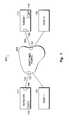
- FIG. 1is a diagram showing long distance mirroring
- FIG. 2illustrates a switched dual fabric, disaster-tolerant storage system
- FIG. 3is a block diagram of the system shown in FIG. 2;
- FIG. 4is a high-level diagram of a remote copy set operation
- FIG. 5is a block diagram showing exemplary controller software architecture
- FIG. 6Ais a flow diagram showing inter-site controller heartbeat timer operation
- FIG. 6Bis a flow diagram showing intra-site controller heartbeat timer operation
- FIG. 7is a flowchart showing synchronous system operation
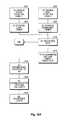
- FIG. 8Ais a flowchart showing asynchronous system operation
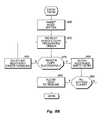
- FIG. 8Bis a flowchart showing a ‘micro-merge’ operation.
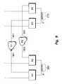
- FIG. 9is a diagram showing an example of a link failover operation.
- the system of the present inventioncomprises a data backup and remote copy system which provides disaster tolerance.
- the present systemprovides a redundant peer-to-peer remote copy function which is implemented as a controller-based replication of one or more LUNs (Logical Unit Numbers) between two separate pairs of array controllers.
- LUNsLogical Unit Numbers
- FIG. 1is a diagram showing long distance mirroring, which is an underlying concept of the present invention.
- the present system 100employs a switched, dual-fabric, Fibre Channel configuration to provide, a disaster tolerant storage system.
- Fibre Channelis the general name of an integrated set of standards developed by the American National Standards Institute (ANSI) which defines protocols for information transfer. Fibre Channel supports multiple physical interface types, multiple protocols over a common physical interface, and a means for interconnecting various interface types.
- a ‘Fibre Channel’may include transmission media such as copper coax or twisted pair copper wires in addition to (or in lieu of) optical fiber.
- an initiating node, or ‘initiator’ 111sends a backup copy of the data to remote ‘target’ node 112 via a Fibre Channel switched fabric 103 .
- a ‘fabric’is a topology (explained in more detail below) which supports dynamic interconnections between nodes through ports connected to the fabric.
- nodes 111 and 112are connected to respective links 105 and 106 via ports 109 .
- a nodeis simply a device which has at least one port to provide access external to the device.
- a nodetypically includes an array controller pair and associated storage array.
- Each port in a nodeis generically termed an N (or NL) port. Ports 109 (array controller ports) are thus N ports. Each port in a fabric is generically termed an F (or FL) port.
- links 105 and 106are connected to switched fabric 103 via F ports 107 . More specifically, these F ports may be standard E ports (extension ports) or E port/FC-BBport pairs, as explained below.
- any node connected to a fabricmay communicate with any other node connected to other F ports of the fabric, using services provided by the fabric.
- all routing of data framesis performed by the fabric, rather than by the ports.
- This any-to-any connection service (‘peer-to-peer’ service) provided by a fabricis integral to a Fibre Channel system. It should be noted that in the context of the present system, although a second host computer 102 is shown (at the target site) in FIG. 1, this computer is not necessary for operation of the system 100 as described herein.
- An underlying operational concept employed by the present system 100is the pairing of volumes (or LUNs) on a local array with those on a remote array.
- the combination of volumesis called a Remote Copy Set.
- a Remote Copy Setthus consists of two volumes, one on the local array, and one on the remote array.
- a Remote Copy Setmight consist of LUN 1 ( 110 ) on a storage array at site 101 and LUN 1 ′ ( 110 ′) on a storage array at site 102 .
- the array designated as the ‘local’ arrayis called the initiator, while the remote array is called the target.
- Various methods for synchronizing the data between the local and remote arrayare possible in the context of the present system.
- synchronization methodsrange from full synchronous to fully asynchronous data transmission, as explained below.
- the system user's ability to choose these methodsprovides the user with the capability to vary system reliability with respect to potential disasters and the recovery after such a disaster.
- the present systemallows choices to be made by the user based on factors which include likelihood of disasters and the critical nature of the user's data.
- FIG. 2illustrates an exemplary configuration of the present invention, which comprises a switched dual fabric, disaster-tolerant storage system 100 .
- the basic topology of the present system 100is that of a switched-based Storage Area Network (SAN).
- SANStorage Area Network
- data storage sites 218 and 219each respectively comprise two hosts 101 / 101 A and 102 / 102 A, and two storage array controllers 201 / 202 and 211 / 212 connected to storage arrays 203 and 213 , respectively.
- Storage arrays 203 and 213typically comprise a plurality of magnetic disk storage devices, but could also include or consist of other types of mass storage devices such as semiconductor memory.
- each host at a particular siteis connected to both fabric elements (i.e., switches) located at that particular site. More specifically, at site 218 , host 101 is connected to switches 204 and 214 via respective paths 231 A and 231 B; host 101 A is connected to the switches via paths 241 A and 241 B. Also located at site 218 are array controllers A 1 (ref. no. 201 ) and A 2 (ref. no. 202 ). Array controller A 1 is connected to switch 204 via paths 221 H and 221 D; array controller A 2 is connected to switch 214 via paths 222 H and 222 D.
- fabric elementsi.e., switches
- Site 219has counterpart array controllers B 1 (ref. no 211 ) and B 2 (ref. no. 212 ), each of which is connected to switches 205 and 215 .
- array controllers B 1 and B 2are connected to switches 205 and 215 via paths 251 D and 252 D, which are, in effect, continuations of paths 221 D and 222 D, respectively.
- each fabric 103 A/ 103 B employed by the present system 100includes two switches interconnected by a high-speed link. More specifically, fabric 103 A comprises switches 204 and 205 connected by link 223 A, while fabric 103 B comprises switches 214 and 215 connected by link 223 B.
- FC-BBFibre Channel Backbone
- each switch pair 204 / 205 and 214 / 215via an Internet link ( 223 A/ 223 B). If the redundant links 223 A and 223 B between the data storage sites 218 / 219 are connected to different ISPs (Internet Service Providers) at the same site, for example, there is a high probability of having at least one link operational at any given time. This is particularly true because of the many redundant paths which are available over the Internet between ISPs. For example, switches 204 and 214 could be connected to separate ISPs, and switches 205 and 215 could also be connected to separate ISPs.
- ISPsInternet Service Providers
- FIG. 3is an exemplary block diagram illustrating additional details of the system shown in FIG. 2 .
- the configuration of the present system 100depicts only one host per site for the sake of simplicity.
- Each host 101 / 102has two adapters 308 which support the dual fabric topology.
- the hoststypically run multi-pathing software that dynamically allows failover between storage paths as well as static load balancing of storage volumes (LUNs) between the paths to the controller-based storage arrays 201 / 202 and 211 / 212 .
- LUNsstorage volumes
- the configuration of system 100allows for applications using either of the storage arrays 203 / 213 to continue running given any failure of either fabric 103 A/ 103 B or either of the storage arrays.
- the array controllers 201 / 202 and 211 / 212 employed by the present system 100have two host ports 109 per array controller, for a total of four connections (ports) per pair in the dual redundant configuration of FIG. 3 .
- Each host port 109preferably has an optical attachment to the switched fabric, for example, a Gigabit Link Module (‘GLM’) interface at the controller, which connects to a Gigabit Converter (‘GBIC’) module comprising the switch interface port 107 .
- Switch interconnection ports 306also preferably comprise GBIC modules.
- Each pair of array controllers 201 / 202 and 211 / 212(and associated storage array) is also called a storage node (e.g., 301 and 302 ), and has a unique Fibre Channel Node Identifier.
- array controller pair A 1 /A 2comprise storage node 301
- array controller pair B 1 /B 2comprise storage node 302 .
- each storage node and each port on the array controllerhas a unique Fibre Channel Port Identifier, such as a World-Wide ID (WWID).
- WWIDWorld-Wide ID
- each unit connected to a given array controlleralso has a WWID, which is the storage node's WWID with an incrementing ‘incarnation’ number. This WWID is used by the host's O/S to allow the local and remote units to be viewed as the ‘same’ storage.
- the array controllers'ports 109are connected somewhat differently than typical dual controller/adapter/channel configurations. Normally, the controller ports'connections to dual transmission channels are cross-coupled, i.e., each controller is connected to both channels. However, in the present system configuration 100 , both ports on array controller A 1 , for example, attach directly to a single fabric via switch 204 . Likewise, both ports on array controller A 2 attach directly to the alternate fabric, via switch 214 . The exact same relative connections exist between array controllers B 1 /B 2 and their respective switches 205 / 215 and associated fabrics. One port of each controller is the ‘host’ port that will serve LUN(s) to the local host 101 / 102 . The other port of each controller is the ‘remote copy’ port, used for disaster tolerant backup.
- FIG. 4is a high-level diagram of a Remote Copy Set operation.
- the present system 100views volumes (or LUNs) on a local array as being paired with counterpart volumes on a remote array.
- a Remote Copy Setis comprised of two volumes, one on the local array, and one on the remote array.
- the local array controlleror ‘initiator’ 301 , presents a local volume that is part of the Remote Copy Set to the local host.
- the host 101performs writes to the local volume on the local array 203 , which copies the incoming write data to the remote volume on the target array 213 .
- LUN Xlogical units
- LUN X′LUN X′ ( 410 ′)
- a Remote Copy Set (RCS)when added on array 203 , points to array 213 , and will cause the contents of the local RCS member on array 203 to be immediately copied to the remote RCS member on array 213 .
- LUN X′ ( 410 ′) on array 213is ready to be used as a backup device. In order to preserve the integrity of the backup copy, local host 101 access to LUN 410 ′ is not allowed during normal operations.
- FIG. 5is a block diagram showing exemplary array controller software architecture employed by the present system 100 .
- peer-to-peer remote copy software (‘PPRC manager’) 515is layered in between host port initiator module 510 and VA (‘Value Added’, such as RAID and caching) software module 520 within each controller (A 1 /A 2 /B 1 /B 2 ).
- VA layer 520is not aware of any PPRC manager 515 context (state change or transfer path).
- Host port target code 505allows only host initiators to connect to the controller port which is a dedicated data replication port.
- the PPRC manager module 515uses containers and services that the VA layer 520 exports. PPRC manager 515 uses interfaces between host port initiator module 510 and VA module 520 for signaling, transfer initiation, and transfer completions. PPRC manager 515 is responsible for managing functions including initiating the connection and heartbeat with the remote controller and initiating the remote copy for incoming host writes (via host port initiator 510 ); initiating I/O operations for performing full copy, log, and merge; handling error recovery (link failover) and peer communication; and maintaining state information.
- Device Services layer 525handles the physical I/O to external devices including the local data storage array and switch.
- FIG. 6Ais an exemplary flow diagram showing the operation of two of the array controller ‘heartbeat’ timers.
- the operation described in FIG. 6Ais best understood in conjunction with reference to the system architecture shown in FIGS. 2 and 3.
- host computer 101sends requests to write data to array 203 via controller A 1 ( 201 ).
- controller A 1sends a write command and the host write data to target array controller B 1 via fabric 103 A (referred to as ‘link 1 ” in FIG. 6 ), so that the data is backed up on array 213 .
- controller A 1starts a command (‘heartbeat’) timer which keeps track of the time between issuance of the write command and a response from the target controller B 1 . If link 1 and controller B 1 are operational, then controller B 1 writes the data to array 213 and, at step 610 , sends an acknowledgement (‘ACK’) back to controller A 1 via link 1 , indicating successful completion of the command.
- a command‘heartbeat’
- controller B 1writes the data to array 213 and, at step 610 , sends an acknowledgement (‘ACK’) back to controller A 1 via link 1 , indicating successful completion of the command.
- controller A 1may also periodically send a Fibre Channel ‘echo’ extended link service command to controller B 1 via link 1 .
- the link echois sent every 10 seconds; however, the exact frequency of the echoes is not critical, nor is it necessary to have the echoes synchronized with any specific source.
- controller A 1sets a second ‘heartbeat’ timer or counter, which can simply be a counter which counts-down using a clock to keep track of the time elapsed since the sending of the link echo.
- controller A 1receives an ‘ACK’ from controller B 1 , indicating that link 1 is operational.
- the command and link timersare preferably set to time out at intervals which are best suited for the cross-link response time between controllers A 1 and B 1 . It is to be noted that a single inter-site link/command timer may be employed in lieu of the two timers described above. A periodic ‘echo’ and associated timer may entirely supplant the command timer, or, alternatively, the echo timer may be replaced by the use of a single timer to ensure that each command sent over each inter-site link is responded to within a predetermined time.
- controller A 1transfers control to controller A 2 , causing A 2 to assume control of backup activities.
- controller A 2proceeds to back up data on storage array 213 by communicating with controller B 2 via link 2 (fabric 103 B).
- controller B 2shares storage array 213 with controller B 1 , at step 630 , B 2 now has access to the volume (e.g., LUN X′) which was previously created by controller B 1 with data sent from controller A 1 .
- the failover processis further described below with respect to FIG. 6 B.
- FIG. 6Bis a flow diagram showing the operation of controller-based ‘heartbeat’ timers, wherein a controller failover operation is effected by a ‘surviving’ controller.
- controllers A 1 ( 201 ) and A 2 ( 202 )are interchangeably represented by the letters ‘C’ and ‘C!’, where “C!” represents C's ‘companion’ controller, i.e., where controller C can be either controller A 1 or A 2 , and controller C! is the companion controller A 2 or A 1 , respectively.
- This terminologyis chosen to illustrate the symmetrical relationship between the two controllers.
- the data from host computer 101is sent over C's link (e.g., link 1 ) to a backup volume (e.g., LUN X) via its counterpart controller (e.g., controller B 1 ) at the remote target site.
- C's linke.g., link 1
- a backup volumee.g., LUN X
- controller B 1counterpart controller
- controllers C and C!set a ‘controller heartbeat’ timer or counter to keep track of the time elapsed between receiving consecutive heartbeat signals (hereinafter referred to as ‘pings’) from the other controller.
- the controller heartbeat timeris set to time out at a predetermined interval, which allows for a worst-case elapsed time between receiving two consecutive pings from the other controller.
- controllers C and C!periodically send pings to each other via DUARTs (Dual Asynchronous Receiver/Transmitters) located at both ends of bus 330 .
- DUARTsDual Asynchronous Receiver/Transmitters
- both controllers C and C!receive a ping from their companion controller. Both controllers then reset their heartbeat timers at step 645 , and each controller awaits another ping from its companion controller.
- controller C!In the situation where, for example, controller C fails (step 647 ), allowing controller C!'s heartbeat timer to time out (at step 650 ), then, at step 655 , controller C! initiates a controller failover operation to move the target LUN on remote storage array to the other controller (e.g., from controller B 1 to controller B 2 ).
- controller C!proceeds by sending backup data to alternate controller (e.g., controller B 2 ) via the alternate link (e.g., link 2 ).
- controller C!has access to the backup volume (e.g., LUN X′) on array 213 .
- connection setupis initiated.
- an initiator controller's host port initiator module 510(FIG. 5) performs discovery to ‘find’ the target controller.
- the host port module 510must use the Fabric's FC-NameServer in order to find controllers which are part of the present system 100 .
- the userspecifies a “target name” which uniquely identifies the remote controller and unit.
- a full copy from the initiator unit to the target unitis initiated.
- the target's datais protected from host access, by the user pre-setting access IDs.
- the steady state operationis possible in two modes, synchronous or asynchronous.
- the remote datais consistent with the local data. All commands that are returned to the host as completed, are completed on both the initiator and the target.
- the remote sitemay lag behind by a bounded number of write I/O operations. All commands that are returned to the host as completed, are completed on the initiator, and may or may not be completed on the target. From a recovery viewpoint the only difference between the operation modes is the level of currency of target members.
- FIG. 7is a flowchart showing synchronous system operation.
- datais written simultaneously to local controller cache memory (or directly to local media if the write request is a write-through command), as well as to the remote subsystems, in real time, before the application I/O is completed, thus ensuring the highest possible data consistency.
- Synchronous replicationis appropriate when this exact consistency is critical to an application such as a banking transaction.
- a drawback to synchronous operationis that long distances between sites mean longer response times, due to the transit time, which might reach unacceptable latency levels, although this situation is somewhat mitigated by write-back cache at the target.
- Asynchronous operationdescribed in the following section, may improve the response time for long-distance backup situations.
- Steady state synchronous operation of system 100proceeds with the following sequence.
- host computer 101issues a write command to local controller A 1 ( 201 ), which receives the command at host port 109 over path 221 h at step 705 .
- the controllerpasses the write command down to the VA level software 530 (FIG. 5) as a normal write.
- VA 530writes the data into its write-back cache through the normal cache manager path (i.e., through the device services layer 525 ). On write completion, VA 530 retains the cache lock and calls the PPRC manager 515 .
- PPRC manager 515sends the write data to remote target controller B 1 ( 211 ) via host port initiator module 510 .
- the datais sent through the remote copy dedicated host port 109 via path 221 D, and across fabric 103 A.
- remote target controller B 1writes data to its write-back cache (or directly to media if a write through operation).
- controller B 1sends the completion status back to initiator controller A 1 .
- VA 530completes the write in the normal path (media write if write through), releases the cache lock, and completes the present operation at step 745 by sending a completion status to the host 101 .
- the cache lockis released by the last entity to use the data. In the case of a remote write, the cache is released by the PPRC manager upon write completion.
- FIG. 8Ais a flowchart showing asynchronous operation the present system 100 .
- Asynchronous operationprovides command completion to the host after the data is safe on the initiating controller, and prior to completion of the target command.
- incoming host write requestsmay exceed the rate at which remote copies to the target can be performed. Copies therefore can be temporarily out of synchronization, but over time that data will converge to the same at all sites.
- Asynchronous operationis useful when transferring large amounts of data, such as during data center migrations or consolidations.
- Asynchronous operation of the present system 100proceeds with the following sequence.
- host computer 101issues a write command to local controller A 1 ( 201 ), which receives the command at host port 109 over path 221 h at step 805 .
- the controllerpasses the write command down to the VA level software 530 (FIG. 5) as a normal write.
- VA 530writes the data into its write-back cache through the normal cache manager path (i.e., through the device services layer 525 ). On write completion, VA 530 retains the cache lock and calls the PPRC manager 515 .
- PPRC Manager“micro-logs” the write transfer LBN extent, as well as the command sequence number and additional context in the controller's non-volatile write-back cache ‘micro-log’. This is done in all situations (not just in error situations), in case the initiator controller (A 1 ) crashes after status is returned to the host, but before the remote copy completes. A small reserved area of cache is dedicated for the micro-log.
- Micro-loggingis done during steady state operation for each asynchronous transfer, not just during error situations.
- the micro-log informationis only used when the controller crashes with outstanding remote copies (or with outstanding logging unit writes).
- the micro-logcontains information to re-issue (‘micro-merge’) the remote copies by either the ‘other’ controller (in this example, controller A 2 ) upon controller failover, or when ‘this’ controller (A 1 ) reboots, in the situation wherein both controllers A 1 and A 2 are down.
- PPRC manager 515calls back VA 530 to complete the host write request, and the host is given the completion status.
- VA 530retains the cache lock and Data Descriptor data structure.
- PPRC manager 515(via host port initiator module 510 ) sends the write data to the remote target. Order preserving context is also passed to host port initiator module 510 .
- remote target controller B 1( 211 ) writes data to its write-back cache (or associated media if a write-through operation). A check is then made by controller A 1 at step 840 to determine whether the remote copy successfully completed. If so, then, at step 845 , target controller B 1 sends the completion status back to initiator controller A 1 .
- PPRC manager 515marks the micro-log entry that the write has completed. The PPRC manager also unlocks the controller cache and de-allocates the Data Descriptor.
- step 840if it was determined that the remote copy operation did not complete successfully, then at step 855 , if the initiator controller (A 1 ) failed while the remote copy was in transit, then a ‘micro-merge’ operation (described below with respect to FIG. 8) is performed. If the remote copy was unsuccessful for other reasons, then at step 860 , other error recovery procedures (not part of the present disclosure) are invoked.
- FIG. 8Bis a flowchart showing a ‘micro-merge’ operation.
- a micro-merge operationis applicable during asynchronous operation when the controller has failed in the window where the host write status has already been returned to the host, but where the remote copy operation (or write history log operation) has not completed.
- these ‘outstanding’ writeswere logged to the initiator controller A 1 's write-back cache, which is also mirrored in partner controller A 2 's (mirrored) write-back cache, so that the cache data is available to controller A 2 if controller A 1 fails. If a controller failover has taken place (as explained in the next section, below), then the partner controller (A 2 ) re-issues these remote copies from the micro-log. Alternatively, if both controllers A 1 and A 2 are down, then controller A 1 itself re-issues these writes when it restarts.
- the following sequencetakes place in the controller during micro-merging mode.
- access to the initiator unit by the hostis inhibited until the micro-merge is complete.
- the initiator unitis read at the LBN described. If the read has an FE (Forced Error), then the FE will be copied to the target (which is highly unlikely, since the area was just written). If the read is unrecoverable, then the target member is removed, because it is impossible to make the target consistent. If the read is successful, the data is then written to the remote target member using the normal remote copy path. Alternatively, if write history logging is active, the data is written to a log unit, as described below in the ‘Write History Logging’ section.
- the micro-logcontains the command sequence number and additional context to issue the commands in the same order received from the host.
- the remote copy of the entrywas successful, then at step 880 , the recorded entry in the micro-log is cleared, and the next entry is ‘re-played’, at step 870 . If the remote copy of the entry was not successful, then at step 895 , then error recovery procedures (not part of the present disclosure) are invoked. After completing all micro-merges (step 885 ), the initiator unit is made accessible to the host at step 890 .
- Link failoveris recovery at the initiator site when one (of two) links has failed.
- Examples of a link failover situationare a target controller rebooting, a switch failure, or an inter-site link failure.
- a link failoveris performed in a first situation. It may also performed in a second situation wherein a remote write has failed due to a link error and its dual partner last had two successful heartbeats (a failed write is held for two successive heartbeats).
- FIG. 9is a diagram showing an example of a link failover operation.
- link 901is lost to initiator controller A 1 .
- controller A 1is in communication with partner controller A 2 , which indicates to A 1 that A 2 's link 902 to controller B 2 is operational.
- initiator controller A 1attempts link failover recovery procedures by attempting to communicate through its dual redundant partner controller A 2 and resume operations.
- a link failoveris accomplished by restarting (re-booting) controller A 1 , to force the initiator unit X on array 203 from controller A 1 to its partner controller A 2 .
- controller A 2then ‘pulls’ target unit Y over to its dual redundant partner B 2 where controller A 2 (the ‘new’ initiator) can access it.
- Link failoveris not performed upon receiving SCSI errors (unit failures) from the remote unit, because the other controller will likely encounter the same error.
- the initiator controllers(A 1 and A 2 ) control the entire failover operation (the target controller, e.g., B 2 is the slave).
Landscapes
- Engineering & Computer Science (AREA)
- Theoretical Computer Science (AREA)
- Quality & Reliability (AREA)
- Physics & Mathematics (AREA)
- General Engineering & Computer Science (AREA)
- General Physics & Mathematics (AREA)
- Information Retrieval, Db Structures And Fs Structures Therefor (AREA)
- Hardware Redundancy (AREA)
Abstract
Description
Claims (16)
Priority Applications (1)
| Application Number | Priority Date | Filing Date | Title |
|---|---|---|---|
| US09/539,745US6601187B1 (en) | 2000-03-31 | 2000-03-31 | System for data replication using redundant pairs of storage controllers, fibre channel fabrics and links therebetween |
Applications Claiming Priority (1)
| Application Number | Priority Date | Filing Date | Title |
|---|---|---|---|
| US09/539,745US6601187B1 (en) | 2000-03-31 | 2000-03-31 | System for data replication using redundant pairs of storage controllers, fibre channel fabrics and links therebetween |
Publications (1)
| Publication Number | Publication Date |
|---|---|
| US6601187B1true US6601187B1 (en) | 2003-07-29 |
Family
ID=27613662
Family Applications (1)
| Application Number | Title | Priority Date | Filing Date |
|---|---|---|---|
| US09/539,745Expired - LifetimeUS6601187B1 (en) | 2000-03-31 | 2000-03-31 | System for data replication using redundant pairs of storage controllers, fibre channel fabrics and links therebetween |
Country Status (1)
| Country | Link |
|---|---|
| US (1) | US6601187B1 (en) |
Cited By (98)
| Publication number | Priority date | Publication date | Assignee | Title |
|---|---|---|---|---|
| US20010047460A1 (en)* | 2000-04-25 | 2001-11-29 | Naotaka Kobayashi | Remote copy system of storage systems connected to fibre network |
| US20020040449A1 (en)* | 2000-10-03 | 2002-04-04 | Manabu Nakano | Backup system and duplicating apparatus |
| US20030115447A1 (en)* | 2001-12-18 | 2003-06-19 | Duc Pham | Network media access architecture and methods for secure storage |
| US20030120699A1 (en)* | 2001-12-24 | 2003-06-26 | Storage Technology Corporation | Variable synchronicity between duplicate transactions |
| US20030126315A1 (en)* | 2001-12-28 | 2003-07-03 | Choon-Seng Tan | Data storage network with host transparent failover controlled by host bus adapter |
| US20030135642A1 (en)* | 2001-12-21 | 2003-07-17 | Andiamo Systems, Inc. | Methods and apparatus for implementing a high availability fibre channel switch |
| US20030163495A1 (en)* | 2002-02-28 | 2003-08-28 | Veritas Software Corporation | Methods and systems to backup data |
| US20030187945A1 (en)* | 2002-03-26 | 2003-10-02 | Clark Lubbers | Flexible data replication mechanism |
| US20030188114A1 (en)* | 2002-03-26 | 2003-10-02 | Clark Lubbers | Data replication with virtualized volumes |
| US6711632B1 (en)* | 1998-08-11 | 2004-03-23 | Ncr Corporation | Method and apparatus for write-back caching with minimal interrupts |
| US20040081087A1 (en)* | 2002-09-09 | 2004-04-29 | Shea Michael John | Method, apparatus and program storage device for verifying existence of a redundant fibre channel path |
| US20040085893A1 (en)* | 2002-10-31 | 2004-05-06 | Linghsiao Wang | High availability ethernet backplane architecture |
| US6766466B1 (en)* | 2001-05-15 | 2004-07-20 | Lsi Logic Corporation | System and method for isolating fibre channel failures in a SAN environment |
| US20050022057A1 (en)* | 2002-05-31 | 2005-01-27 | Yoshifumi Takamoto | Storage area network system |
| US20050091391A1 (en)* | 2003-10-28 | 2005-04-28 | Burton David A. | Data replication in data storage systems |
| US20050114730A1 (en)* | 2003-11-26 | 2005-05-26 | Hitachi, Ltd. | Remote copy network |
| US20050114407A1 (en)* | 2003-11-25 | 2005-05-26 | International Business Machines Corporation | High-performance asynchronous peer-to-peer remote copy for databases |
| US20050114741A1 (en)* | 2003-11-20 | 2005-05-26 | International Business Machines Corporation | Method, system, and program for transmitting input/output requests from a primary controller to a secondary controller |
| US20050114740A1 (en)* | 2003-11-20 | 2005-05-26 | International Business Machines (Ibm) Corporation | Concurrent PPRC/FCP and host access to secondary PPRC/FCP device through independent error management |
| US20050114488A1 (en)* | 2003-11-20 | 2005-05-26 | International Business Machines Corporation | Method, system, and article of manufacture for validating a remote device |
| US20050138310A1 (en)* | 2003-12-17 | 2005-06-23 | Takashi Horiuchi | Backup system and method and program |
| US20050148891A1 (en)* | 2004-01-07 | 2005-07-07 | Hitachi, Ltd. | Storage system, control method for storage system, and storage control unit |
| US20050160243A1 (en)* | 2001-06-01 | 2005-07-21 | Lubbers Clark E. | Point in time storage copy |
| US6922414B1 (en)* | 2000-08-21 | 2005-07-26 | Hewlett-Packard Development Company, L.P. | Apparatus and method for dynamic command queue depth adjustment for storage area network nodes |
| US20050172073A1 (en)* | 2004-01-30 | 2005-08-04 | Hewlett-Packard Development Company, L.P. | Storage system including capability to move a virtual storage device group without moving data |
| US20050193246A1 (en)* | 2004-02-19 | 2005-09-01 | Marconi Communications, Inc. | Method, apparatus and software for preventing switch failures in the presence of faults |
| US20050193248A1 (en)* | 2004-02-24 | 2005-09-01 | Hideomi Idei | Computer system for recovering data based on priority of the data |
| US20050203874A1 (en)* | 2001-10-22 | 2005-09-15 | Lubbers Clark E. | Multi-controller data processing |
| US6952734B1 (en) | 2000-08-21 | 2005-10-04 | Hewlett-Packard Development Company, L.P. | Method for recovery of paths between storage area network nodes with probationary period and desperation repair |
| US20050229021A1 (en)* | 2002-03-28 | 2005-10-13 | Clark Lubbers | Automatic site failover |
| US20050235109A1 (en)* | 2003-05-21 | 2005-10-20 | Fujitsu Limited | Storage system |
| US20050240681A1 (en)* | 2004-04-27 | 2005-10-27 | Hitachi, Ltd. | Communication device, storage system and a communication method |
| US20050262298A1 (en)* | 2002-03-26 | 2005-11-24 | Clark Lubbers | System and method for ensuring merge completion in a storage area network |
| US7020089B2 (en) | 2004-03-08 | 2006-03-28 | Hitachi, Ltd. | Information processing apparatus and method of controlling the information processing apparatus |
| US7043663B1 (en)* | 2001-11-15 | 2006-05-09 | Xiotech Corporation | System and method to monitor and isolate faults in a storage area network |
| US20060112032A1 (en)* | 2004-10-29 | 2006-05-25 | International Business Machines Corporation | Two stage method for dynamically determining primary adapter in a heterogeneous N-way adapter configuration |
| US7080133B1 (en)* | 2000-07-17 | 2006-07-18 | International Business Machines Corporation | Method and system for configuring a computer network |
| US20060168410A1 (en)* | 2005-01-24 | 2006-07-27 | Andruszkiewicz John J | Systems and methods of merge operations of a storage subsystem |
| US20060168403A1 (en)* | 2005-01-27 | 2006-07-27 | Curt Kolovson | Intelligent cache management |
| US20060171055A1 (en)* | 2005-01-31 | 2006-08-03 | Ballard Curtis C | Recording errors in tape drives |
| US20060182050A1 (en)* | 2005-01-28 | 2006-08-17 | Hewlett-Packard Development Company, L.P. | Storage replication system with data tracking |
| US20060230243A1 (en)* | 2005-04-06 | 2006-10-12 | Robert Cochran | Cascaded snapshots |
| US7127633B1 (en)* | 2001-11-15 | 2006-10-24 | Xiotech Corporation | System and method to failover storage area network targets from one interface to another |
| US20070022263A1 (en)* | 2005-07-22 | 2007-01-25 | John Fandel | Data synchronization management |
| US20070025008A1 (en)* | 2005-07-27 | 2007-02-01 | Ballard Curtis C | Tape drive error management |
| US7194538B1 (en) | 2002-06-04 | 2007-03-20 | Veritas Operating Corporation | Storage area network (SAN) management system for discovering SAN components using a SAN management server |
| US20070079171A1 (en)* | 2005-09-30 | 2007-04-05 | Mehrdad Aidun | No data loss it disaster recovery over extended distances |
| US20070083626A1 (en)* | 2005-10-06 | 2007-04-12 | Walker Philip M | Secure data scrubbing |
| US20070094393A1 (en)* | 2005-10-24 | 2007-04-26 | Cochran Robert A | Intelligent logical unit provisioning |
| US20080015878A1 (en)* | 2006-07-17 | 2008-01-17 | Yahoo! Inc. | Real-time user profile platform for targeted online advertisement and personalization |
| US7334062B1 (en) | 2003-07-22 | 2008-02-19 | Symantec Operating Corporation | Technique to monitor application behavior and tune replication performance |
| US20080065824A1 (en)* | 2006-09-07 | 2008-03-13 | International Business Machines Corporation | Establishing communications across virtual enclosure boundaries |
| US7353353B2 (en) | 2001-01-17 | 2008-04-01 | Hewlett-Packard Development Company, L.P. | File security management |
| US7401338B1 (en) | 2002-09-27 | 2008-07-15 | Symantec Operating Corporation | System and method for an access layer application programming interface for managing heterogeneous components of a storage area network |
| US7403987B1 (en) | 2001-06-29 | 2008-07-22 | Symantec Operating Corporation | Transactional SAN management |
| US20080178188A1 (en)* | 2007-01-19 | 2008-07-24 | Thomas Cooke | Critical resource management |
| US20080215806A1 (en)* | 2007-03-01 | 2008-09-04 | Feather Stanley S | Access control management |
| US20080212222A1 (en)* | 2007-03-01 | 2008-09-04 | Stan Feather | Access control management |
| US20080244295A1 (en)* | 2005-10-03 | 2008-10-02 | Hitachi, Ltd. | Method of saving power consumed by a storage system |
| US7467268B2 (en) | 2006-04-14 | 2008-12-16 | Hewlett-Packard Development Company, L.P. | Concurrent data restore and background copy operations in storage networks |
| US7529834B1 (en)* | 2000-06-02 | 2009-05-05 | Hewlett-Packard Development Company, L.P. | Method and system for cooperatively backing up data on computers in a network |
| US7631068B1 (en)* | 2003-04-14 | 2009-12-08 | Symantec Operating Corporation | Topology for showing data protection activity |
| US20100011176A1 (en)* | 2008-07-11 | 2010-01-14 | Burkey Todd R | Performance of binary bulk IO operations on virtual disks by interleaving |
| US20100049822A1 (en)* | 2003-04-23 | 2010-02-25 | Dot Hill Systems Corporation | Network, storage appliance, and method for externalizing an external I/O link between a server and a storage controller integrated within the storage appliance chassis |
| US7694079B2 (en) | 2007-04-04 | 2010-04-06 | Hewlett-Packard Development Company, L.P. | Tagged sequential read operations |
| US20100095160A1 (en)* | 2008-10-14 | 2010-04-15 | Dickens Louie A | Storage Area Network (SAN) Link Integrity Tester |
| US7702757B2 (en) | 2004-04-07 | 2010-04-20 | Xiotech Corporation | Method, apparatus and program storage device for providing control to a networked storage architecture |
| US20100250867A1 (en)* | 2009-03-30 | 2010-09-30 | The Boeing Company | Computer architectures using shared storage |
| US20100299553A1 (en)* | 2009-05-25 | 2010-11-25 | Alibaba Group Holding Limited | Cache data processing using cache cluster with configurable modes |
| US20110023046A1 (en)* | 2009-07-22 | 2011-01-27 | Stephen Gold | Mitigating resource usage during virtual storage replication |
| US7886031B1 (en) | 2002-06-04 | 2011-02-08 | Symantec Operating Corporation | SAN configuration utility |
| US7885256B1 (en) | 2003-05-30 | 2011-02-08 | Symantec Operating Corporation | SAN fabric discovery |
| US20110066754A1 (en)* | 2009-09-15 | 2011-03-17 | Stryker Donald J | Intelligent Device and Media Server Selection for Optimized Backup Image Duplication |
| US20110066799A1 (en)* | 2009-09-15 | 2011-03-17 | Stephen Gold | Enhanced virtual storage replication |
| US7925758B1 (en) | 2006-11-09 | 2011-04-12 | Symantec Operating Corporation | Fibre accelerated pipe data transport |
| US20110099360A1 (en)* | 2009-10-26 | 2011-04-28 | International Business Machines Corporation | Addressing Node Failure During A Hyperswap Operation |
| US20110191749A1 (en)* | 2010-01-29 | 2011-08-04 | Martijn Van Liebergen | System and method for generating enterprise applications |
| US8019849B1 (en) | 2002-09-13 | 2011-09-13 | Symantec Operating Corporation | Server-side storage area network management interface |
| US20110231172A1 (en)* | 2010-03-21 | 2011-09-22 | Stephen Gold | Determining impact of virtual storage backup jobs |
| US8060630B1 (en) | 2002-11-27 | 2011-11-15 | Symantec Operating Corporation | Creating and configuring virtual fabrics in storage area networks |
| US20130198562A1 (en)* | 2012-01-31 | 2013-08-01 | Symantec Corporation | Method and system for cluster wide adaptive i/o scheduling by a multipathing driver |
| US8711864B1 (en) | 2010-03-30 | 2014-04-29 | Chengdu Huawei Symantec Technologies Co., Ltd. | System and method for supporting fibre channel over ethernet communication |
| US8793352B2 (en) | 2008-07-01 | 2014-07-29 | International Business Machines Corporation | Storage area network configuration |
| US9009724B2 (en) | 2010-09-24 | 2015-04-14 | Hewlett-Packard Development Company, L.P. | Load balancing data access in virtualized storage nodes |
| US20150134923A1 (en)* | 2013-11-08 | 2015-05-14 | International Business Machines Corporation | Replicating data across controllers |
| WO2015069225A1 (en)* | 2013-11-05 | 2015-05-14 | Hitachi, Ltd. | Method and apparatus for avoiding performance decrease in high availability configuration |
| US9098462B1 (en) | 2010-09-14 | 2015-08-04 | The Boeing Company | Communications via shared memory |
| US9268835B2 (en) | 2010-12-28 | 2016-02-23 | Amazon Technologies, Inc. | Data replication framework |
| US9430163B1 (en) | 2015-12-15 | 2016-08-30 | International Business Machines Corporation | Implementing synchronization for remote disk mirroring |
| US9449065B1 (en)* | 2010-12-28 | 2016-09-20 | Amazon Technologies, Inc. | Data replication framework |
| US9734199B1 (en) | 2010-12-28 | 2017-08-15 | Amazon Technologies, Inc. | Data replication framework |
| US20180129624A1 (en)* | 2016-11-10 | 2018-05-10 | Nxp Usa, Inc. | Method and apparatus for handling outstanding interconnect transactions |
| US10198492B1 (en) | 2010-12-28 | 2019-02-05 | Amazon Technologies, Inc. | Data replication framework |
| US10296429B2 (en)* | 2014-07-25 | 2019-05-21 | Hitachi, Ltd. | Storage device |
| US10452284B2 (en)* | 2013-02-05 | 2019-10-22 | International Business Machines Corporation | Storage system based host computer monitoring |
| US10496608B2 (en)* | 2009-10-28 | 2019-12-03 | Sandisk Il Ltd. | Synchronizing changes in a file system which are initiated by a storage device and a host device |
| US10620842B1 (en)* | 2015-12-30 | 2020-04-14 | EMC IP Holding Company LLC | Maintaining write consistency on distributed multiple page writes |
| US10969986B2 (en) | 2018-11-02 | 2021-04-06 | EMC IP Holding Company LLC | Data storage system with storage container pairing for remote replication |
Citations (8)
| Publication number | Priority date | Publication date | Assignee | Title |
|---|---|---|---|---|
| US5274645A (en) | 1990-03-02 | 1993-12-28 | Micro Technology, Inc. | Disk array system |
| US5544347A (en)* | 1990-09-24 | 1996-08-06 | Emc Corporation | Data storage system controlled remote data mirroring with respectively maintained data indices |
| US5768623A (en) | 1995-09-19 | 1998-06-16 | International Business Machines Corporation | System and method for sharing multiple storage arrays by dedicating adapters as primary controller and secondary controller for arrays reside in different host computers |
| US5790775A (en) | 1995-10-23 | 1998-08-04 | Digital Equipment Corporation | Host transparent storage controller failover/failback of SCSI targets and associated units |
| US6178521B1 (en)* | 1998-05-22 | 2001-01-23 | Compaq Computer Corporation | Method and apparatus for disaster tolerant computer system using cascaded storage controllers |
| US6363462B1 (en)* | 1997-03-31 | 2002-03-26 | Lsi Logic Corporation | Storage controller providing automatic retention and deletion of synchronous back-up data |
| US6401170B1 (en)* | 1999-08-18 | 2002-06-04 | Digi-Data Corporation | RAID systems during non-fault and faulty conditions on a fiber channel arbitrated loop, SCSI bus or switch fabric configuration |
| US6457098B1 (en)* | 1998-12-23 | 2002-09-24 | Lsi Logic Corporation | Methods and apparatus for coordinating shared multiple raid controller access to common storage devices |
- 2000
- 2000-03-31USUS09/539,745patent/US6601187B1/ennot_activeExpired - Lifetime
Patent Citations (8)
| Publication number | Priority date | Publication date | Assignee | Title |
|---|---|---|---|---|
| US5274645A (en) | 1990-03-02 | 1993-12-28 | Micro Technology, Inc. | Disk array system |
| US5544347A (en)* | 1990-09-24 | 1996-08-06 | Emc Corporation | Data storage system controlled remote data mirroring with respectively maintained data indices |
| US5768623A (en) | 1995-09-19 | 1998-06-16 | International Business Machines Corporation | System and method for sharing multiple storage arrays by dedicating adapters as primary controller and secondary controller for arrays reside in different host computers |
| US5790775A (en) | 1995-10-23 | 1998-08-04 | Digital Equipment Corporation | Host transparent storage controller failover/failback of SCSI targets and associated units |
| US6363462B1 (en)* | 1997-03-31 | 2002-03-26 | Lsi Logic Corporation | Storage controller providing automatic retention and deletion of synchronous back-up data |
| US6178521B1 (en)* | 1998-05-22 | 2001-01-23 | Compaq Computer Corporation | Method and apparatus for disaster tolerant computer system using cascaded storage controllers |
| US6457098B1 (en)* | 1998-12-23 | 2002-09-24 | Lsi Logic Corporation | Methods and apparatus for coordinating shared multiple raid controller access to common storage devices |
| US6401170B1 (en)* | 1999-08-18 | 2002-06-04 | Digi-Data Corporation | RAID systems during non-fault and faulty conditions on a fiber channel arbitrated loop, SCSI bus or switch fabric configuration |
Non-Patent Citations (1)
| Title |
|---|
| Sicola, Stephen J. et al., U.S. Patent Application, Fault Tolerant Storage Controller Utilizing Tightly Coupled Dual Controller Modules, Ser. No. 08/071,710, filed Jun. 4, 1993, pp. 1-90. |
Cited By (174)
| Publication number | Priority date | Publication date | Assignee | Title |
|---|---|---|---|---|
| US6711632B1 (en)* | 1998-08-11 | 2004-03-23 | Ncr Corporation | Method and apparatus for write-back caching with minimal interrupts |
| US20010047460A1 (en)* | 2000-04-25 | 2001-11-29 | Naotaka Kobayashi | Remote copy system of storage systems connected to fibre network |
| US7529834B1 (en)* | 2000-06-02 | 2009-05-05 | Hewlett-Packard Development Company, L.P. | Method and system for cooperatively backing up data on computers in a network |
| US7080133B1 (en)* | 2000-07-17 | 2006-07-18 | International Business Machines Corporation | Method and system for configuring a computer network |
| US6952734B1 (en) | 2000-08-21 | 2005-10-04 | Hewlett-Packard Development Company, L.P. | Method for recovery of paths between storage area network nodes with probationary period and desperation repair |
| US6922414B1 (en)* | 2000-08-21 | 2005-07-26 | Hewlett-Packard Development Company, L.P. | Apparatus and method for dynamic command queue depth adjustment for storage area network nodes |
| US20020040449A1 (en)* | 2000-10-03 | 2002-04-04 | Manabu Nakano | Backup system and duplicating apparatus |
| US7082548B2 (en)* | 2000-10-03 | 2006-07-25 | Fujitsu Limited | Backup system and duplicating apparatus |
| US7353353B2 (en) | 2001-01-17 | 2008-04-01 | Hewlett-Packard Development Company, L.P. | File security management |
| US6766466B1 (en)* | 2001-05-15 | 2004-07-20 | Lsi Logic Corporation | System and method for isolating fibre channel failures in a SAN environment |
| US20050160243A1 (en)* | 2001-06-01 | 2005-07-21 | Lubbers Clark E. | Point in time storage copy |
| US7290102B2 (en) | 2001-06-01 | 2007-10-30 | Hewlett-Packard Development Company, L.P. | Point in time storage copy |
| US8180872B1 (en) | 2001-06-29 | 2012-05-15 | Symantec Operating Corporation | Common data model for heterogeneous SAN components |
| US7685261B1 (en)* | 2001-06-29 | 2010-03-23 | Symantec Operating Corporation | Extensible architecture for the centralized discovery and management of heterogeneous SAN components |
| US7506040B1 (en) | 2001-06-29 | 2009-03-17 | Symantec Operating Corporation | System and method for storage area network management |
| US7403987B1 (en) | 2001-06-29 | 2008-07-22 | Symantec Operating Corporation | Transactional SAN management |
| US20050203874A1 (en)* | 2001-10-22 | 2005-09-15 | Lubbers Clark E. | Multi-controller data processing |
| US7478215B2 (en) | 2001-10-22 | 2009-01-13 | Hewlett-Packard Development Company, L.P. | Multi-controller write operations |
| US7043663B1 (en)* | 2001-11-15 | 2006-05-09 | Xiotech Corporation | System and method to monitor and isolate faults in a storage area network |
| US7127633B1 (en)* | 2001-11-15 | 2006-10-24 | Xiotech Corporation | System and method to failover storage area network targets from one interface to another |
| US20030115447A1 (en)* | 2001-12-18 | 2003-06-19 | Duc Pham | Network media access architecture and methods for secure storage |
| US20030135642A1 (en)* | 2001-12-21 | 2003-07-17 | Andiamo Systems, Inc. | Methods and apparatus for implementing a high availability fibre channel switch |
| US7293105B2 (en)* | 2001-12-21 | 2007-11-06 | Cisco Technology, Inc. | Methods and apparatus for implementing a high availability fibre channel switch |
| US20030120699A1 (en)* | 2001-12-24 | 2003-06-26 | Storage Technology Corporation | Variable synchronicity between duplicate transactions |
| US20030126315A1 (en)* | 2001-12-28 | 2003-07-03 | Choon-Seng Tan | Data storage network with host transparent failover controlled by host bus adapter |
| US7111084B2 (en)* | 2001-12-28 | 2006-09-19 | Hewlett-Packard Development Company, L.P. | Data storage network with host transparent failover controlled by host bus adapter |
| US20030163495A1 (en)* | 2002-02-28 | 2003-08-28 | Veritas Software Corporation | Methods and systems to backup data |
| US6947981B2 (en)* | 2002-03-26 | 2005-09-20 | Hewlett-Packard Development Company, L.P. | Flexible data replication mechanism |
| US20030188114A1 (en)* | 2002-03-26 | 2003-10-02 | Clark Lubbers | Data replication with virtualized volumes |
| US6880052B2 (en)* | 2002-03-26 | 2005-04-12 | Hewlett-Packard Development Company, Lp | Storage area network, data replication and storage controller, and method for replicating data using virtualized volumes |
| US20050262298A1 (en)* | 2002-03-26 | 2005-11-24 | Clark Lubbers | System and method for ensuring merge completion in a storage area network |
| US20050243611A1 (en)* | 2002-03-26 | 2005-11-03 | Clark Lubbers | Flexible data replication mechanism |
| US7137032B2 (en) | 2002-03-26 | 2006-11-14 | Hewlett-Packard Development Company, L.P. | System and method for ensuring merge completion in a storage area network |
| US20030187945A1 (en)* | 2002-03-26 | 2003-10-02 | Clark Lubbers | Flexible data replication mechanism |
| US20050229021A1 (en)* | 2002-03-28 | 2005-10-13 | Clark Lubbers | Automatic site failover |
| US7542987B2 (en) | 2002-03-28 | 2009-06-02 | Hewlett-Packard Development Company, L.P. | Automatic site failover |
| US7315960B2 (en)* | 2002-05-31 | 2008-01-01 | Hitachi, Ltd. | Storage area network system |
| US20050022057A1 (en)* | 2002-05-31 | 2005-01-27 | Yoshifumi Takamoto | Storage area network system |
| US7886031B1 (en) | 2002-06-04 | 2011-02-08 | Symantec Operating Corporation | SAN configuration utility |
| US7194538B1 (en) | 2002-06-04 | 2007-03-20 | Veritas Operating Corporation | Storage area network (SAN) management system for discovering SAN components using a SAN management server |
| US7672226B2 (en)* | 2002-09-09 | 2010-03-02 | Xiotech Corporation | Method, apparatus and program storage device for verifying existence of a redundant fibre channel path |
| US20040081087A1 (en)* | 2002-09-09 | 2004-04-29 | Shea Michael John | Method, apparatus and program storage device for verifying existence of a redundant fibre channel path |
| US8019849B1 (en) | 2002-09-13 | 2011-09-13 | Symantec Operating Corporation | Server-side storage area network management interface |
| US7401338B1 (en) | 2002-09-27 | 2008-07-15 | Symantec Operating Corporation | System and method for an access layer application programming interface for managing heterogeneous components of a storage area network |
| US20040085893A1 (en)* | 2002-10-31 | 2004-05-06 | Linghsiao Wang | High availability ethernet backplane architecture |
| US7835265B2 (en)* | 2002-10-31 | 2010-11-16 | Conexant Systems, Inc. | High availability Ethernet backplane architecture |
| US8060630B1 (en) | 2002-11-27 | 2011-11-15 | Symantec Operating Corporation | Creating and configuring virtual fabrics in storage area networks |
| US7631068B1 (en)* | 2003-04-14 | 2009-12-08 | Symantec Operating Corporation | Topology for showing data protection activity |
| US20100064169A1 (en)* | 2003-04-23 | 2010-03-11 | Dot Hill Systems Corporation | Network storage appliance with integrated server and redundant storage controllers |
| US8185777B2 (en)* | 2003-04-23 | 2012-05-22 | Dot Hill Systems Corporation | Network storage appliance with integrated server and redundant storage controllers |
| US20100049822A1 (en)* | 2003-04-23 | 2010-02-25 | Dot Hill Systems Corporation | Network, storage appliance, and method for externalizing an external I/O link between a server and a storage controller integrated within the storage appliance chassis |
| US9176835B2 (en) | 2003-04-23 | 2015-11-03 | Dot Hill Systems Corporation | Network, storage appliance, and method for externalizing an external I/O link between a server and a storage controller integrated within the storage appliance chassis |
| US8738869B2 (en)* | 2003-05-21 | 2014-05-27 | Fujitsu Limited | Storage system including a plurality of modules having different control information |
| US20050235109A1 (en)* | 2003-05-21 | 2005-10-20 | Fujitsu Limited | Storage system |
| US7885256B1 (en) | 2003-05-30 | 2011-02-08 | Symantec Operating Corporation | SAN fabric discovery |
| US7334062B1 (en) | 2003-07-22 | 2008-02-19 | Symantec Operating Corporation | Technique to monitor application behavior and tune replication performance |
| US20070011213A1 (en)* | 2003-10-28 | 2007-01-11 | Burton David A | Systems and methods of asynchronous data replication |
| US7143122B2 (en)* | 2003-10-28 | 2006-11-28 | Pillar Data Systems, Inc. | Data replication in data storage systems |
| US20050091391A1 (en)* | 2003-10-28 | 2005-04-28 | Burton David A. | Data replication in data storage systems |
| US7685176B2 (en) | 2003-10-28 | 2010-03-23 | Pillar Data Systems, Inc. | Systems and methods of asynchronous data replication |
| US20050114488A1 (en)* | 2003-11-20 | 2005-05-26 | International Business Machines Corporation | Method, system, and article of manufacture for validating a remote device |
| US20050114740A1 (en)* | 2003-11-20 | 2005-05-26 | International Business Machines (Ibm) Corporation | Concurrent PPRC/FCP and host access to secondary PPRC/FCP device through independent error management |
| US20050114741A1 (en)* | 2003-11-20 | 2005-05-26 | International Business Machines Corporation | Method, system, and program for transmitting input/output requests from a primary controller to a secondary controller |
| US7251743B2 (en)* | 2003-11-20 | 2007-07-31 | International Business Machines Corporation | Method, system, and program for transmitting input/output requests from a primary controller to a secondary controller |
| US7562137B2 (en)* | 2003-11-20 | 2009-07-14 | Internatioal Business Machines Corporation | Method for validating a remote device |
| US7197663B2 (en)* | 2003-11-20 | 2007-03-27 | International Business Machines Corporation | Concurrent PPRC/FCP and host access to secondary PPRC/FCP device through independent error management |
| US8214328B2 (en) | 2003-11-25 | 2012-07-03 | International Business Machines Corporation | High-performance asynchronous peer-to-peer remote copy for databases |
| US20050114407A1 (en)* | 2003-11-25 | 2005-05-26 | International Business Machines Corporation | High-performance asynchronous peer-to-peer remote copy for databases |
| US20050114730A1 (en)* | 2003-11-26 | 2005-05-26 | Hitachi, Ltd. | Remote copy network |
| US7305531B2 (en) | 2003-11-26 | 2007-12-04 | Hitachi, Ltd. | Remote copy network |
| US7055011B2 (en) | 2003-11-26 | 2006-05-30 | Hitachi, Ltd. | Remote copy network |
| US7809909B2 (en) | 2003-11-26 | 2010-10-05 | Hitachi, Ltd. | Remote copy network |
| US20080065848A1 (en)* | 2003-11-26 | 2008-03-13 | Hitachi, Ltd. | Remote Copy Network |
| US7047376B2 (en)* | 2003-12-17 | 2006-05-16 | Hitachi, Ltd. | Backup system and method and program |
| US20050138310A1 (en)* | 2003-12-17 | 2005-06-23 | Takashi Horiuchi | Backup system and method and program |
| US7124264B2 (en) | 2004-01-07 | 2006-10-17 | Hitachi, Ltd. | Storage system, control method for storage system, and storage control unit |
| US20050148891A1 (en)* | 2004-01-07 | 2005-07-07 | Hitachi, Ltd. | Storage system, control method for storage system, and storage control unit |
| US8006056B2 (en)* | 2004-01-30 | 2011-08-23 | Hewlett-Packard Development Company, L.P. | Storage system including capability to move a virtual storage device group without moving data |
| US20050172073A1 (en)* | 2004-01-30 | 2005-08-04 | Hewlett-Packard Development Company, L.P. | Storage system including capability to move a virtual storage device group without moving data |
| US20050193246A1 (en)* | 2004-02-19 | 2005-09-01 | Marconi Communications, Inc. | Method, apparatus and software for preventing switch failures in the presence of faults |
| US20050193248A1 (en)* | 2004-02-24 | 2005-09-01 | Hideomi Idei | Computer system for recovering data based on priority of the data |
| US7266718B2 (en) | 2004-02-24 | 2007-09-04 | Hitachi, Ltd. | Computer system for recovering data based on priority of the data |
| US7519001B2 (en) | 2004-03-08 | 2009-04-14 | Hitachi, Ltd. | Information processing apparatus and method of controlling the information processing apparatus |
| US7020089B2 (en) | 2004-03-08 | 2006-03-28 | Hitachi, Ltd. | Information processing apparatus and method of controlling the information processing apparatus |
| US20060092848A1 (en)* | 2004-03-08 | 2006-05-04 | Hitachi, Ltd. | Information processing apparatus and method of controlling the information processing apparatus |
| US7702757B2 (en) | 2004-04-07 | 2010-04-20 | Xiotech Corporation | Method, apparatus and program storage device for providing control to a networked storage architecture |
| US7092982B2 (en)* | 2004-04-27 | 2006-08-15 | Hitachi, Ltd. | Storage system with method of minimizing redundant transmissions over a plurality of communication paths |
| US20050240681A1 (en)* | 2004-04-27 | 2005-10-27 | Hitachi, Ltd. | Communication device, storage system and a communication method |
| US20060112032A1 (en)* | 2004-10-29 | 2006-05-25 | International Business Machines Corporation | Two stage method for dynamically determining primary adapter in a heterogeneous N-way adapter configuration |
| US7493370B2 (en)* | 2004-10-29 | 2009-02-17 | International Business Machines Corporation | Two stage method for dynamically determining primary adapter in a heterogeneous N-way adapter configuration |
| US8195589B2 (en) | 2004-10-29 | 2012-06-05 | International Business Machines Corporation | Apparatus for dynamically determining primary adapter in a heterogeneous N-way adapter configuration |
| US20060168410A1 (en)* | 2005-01-24 | 2006-07-27 | Andruszkiewicz John J | Systems and methods of merge operations of a storage subsystem |
| US20060168403A1 (en)* | 2005-01-27 | 2006-07-27 | Curt Kolovson | Intelligent cache management |
| US8127088B2 (en) | 2005-01-27 | 2012-02-28 | Hewlett-Packard Development Company, L.P. | Intelligent cache management |
| US20060182050A1 (en)* | 2005-01-28 | 2006-08-17 | Hewlett-Packard Development Company, L.P. | Storage replication system with data tracking |
| US7301718B2 (en) | 2005-01-31 | 2007-11-27 | Hewlett-Packard Development Company, L.P. | Recording errors in tape drives |
| US20060171055A1 (en)* | 2005-01-31 | 2006-08-03 | Ballard Curtis C | Recording errors in tape drives |
| US20060230243A1 (en)* | 2005-04-06 | 2006-10-12 | Robert Cochran | Cascaded snapshots |
| US20070022263A1 (en)* | 2005-07-22 | 2007-01-25 | John Fandel | Data synchronization management |
| US7779218B2 (en) | 2005-07-22 | 2010-08-17 | Hewlett-Packard Development Company, L.P. | Data synchronization management |
| US20070025008A1 (en)* | 2005-07-27 | 2007-02-01 | Ballard Curtis C | Tape drive error management |
| US7206156B2 (en) | 2005-07-27 | 2007-04-17 | Hewlett-Packard Development Company, L.P. | Tape drive error management |
| US20090271658A1 (en)* | 2005-09-30 | 2009-10-29 | Lockheed Martin Corporation | No data loss it disaster recovery over extended distances |
| US20070079171A1 (en)* | 2005-09-30 | 2007-04-05 | Mehrdad Aidun | No data loss it disaster recovery over extended distances |
| US7577868B2 (en) | 2005-09-30 | 2009-08-18 | Lockheed Martin Corporation | No data loss IT disaster recovery over extended distances |
| US20080244295A1 (en)* | 2005-10-03 | 2008-10-02 | Hitachi, Ltd. | Method of saving power consumed by a storage system |
| US7908503B2 (en)* | 2005-10-03 | 2011-03-15 | Hitachi, Ltd. | Method of saving power consumed by a storage system |
| US20070083626A1 (en)* | 2005-10-06 | 2007-04-12 | Walker Philip M | Secure data scrubbing |
| US7325078B2 (en) | 2005-10-06 | 2008-01-29 | Hewlett-Packard Development Company, L.P. | Secure data scrubbing |
| US7721053B2 (en) | 2005-10-24 | 2010-05-18 | Hewlett-Packard Development Company, L.P. | Intelligent logical unit provisioning |
| US20070094393A1 (en)* | 2005-10-24 | 2007-04-26 | Cochran Robert A | Intelligent logical unit provisioning |
| US7467268B2 (en) | 2006-04-14 | 2008-12-16 | Hewlett-Packard Development Company, L.P. | Concurrent data restore and background copy operations in storage networks |
| US20080015878A1 (en)* | 2006-07-17 | 2008-01-17 | Yahoo! Inc. | Real-time user profile platform for targeted online advertisement and personalization |
| US7761738B2 (en)* | 2006-09-07 | 2010-07-20 | International Business Machines Corporation | Establishing communications across virtual enclosure boundaries |
| US20080065824A1 (en)* | 2006-09-07 | 2008-03-13 | International Business Machines Corporation | Establishing communications across virtual enclosure boundaries |
| US7925758B1 (en) | 2006-11-09 | 2011-04-12 | Symantec Operating Corporation | Fibre accelerated pipe data transport |
| US7934027B2 (en) | 2007-01-19 | 2011-04-26 | Hewlett-Packard Development Company, L.P. | Critical resource management |
| US20080178188A1 (en)* | 2007-01-19 | 2008-07-24 | Thomas Cooke | Critical resource management |
| US7861031B2 (en) | 2007-03-01 | 2010-12-28 | Hewlett-Packard Development Company, L.P. | Access control management |
| US20080215806A1 (en)* | 2007-03-01 | 2008-09-04 | Feather Stanley S | Access control management |
| US20080212222A1 (en)* | 2007-03-01 | 2008-09-04 | Stan Feather | Access control management |
| US8024514B2 (en) | 2007-03-01 | 2011-09-20 | Hewlett-Packard Development Company, L.P. | Access control management |
| US7694079B2 (en) | 2007-04-04 | 2010-04-06 | Hewlett-Packard Development Company, L.P. | Tagged sequential read operations |
| US8793352B2 (en) | 2008-07-01 | 2014-07-29 | International Business Machines Corporation | Storage area network configuration |
| US20100011176A1 (en)* | 2008-07-11 | 2010-01-14 | Burkey Todd R | Performance of binary bulk IO operations on virtual disks by interleaving |
| US8065571B2 (en) | 2008-10-14 | 2011-11-22 | International Business Machines Corporation | Storage area network (SAN) link integrity tester |
| US20100095160A1 (en)* | 2008-10-14 | 2010-04-15 | Dickens Louie A | Storage Area Network (SAN) Link Integrity Tester |
| US9098562B2 (en)* | 2009-03-30 | 2015-08-04 | The Boeing Company | Computer architectures using shared storage |
| US8972515B2 (en)* | 2009-03-30 | 2015-03-03 | The Boeing Company | Computer architectures using shared storage |
| US9690839B2 (en) | 2009-03-30 | 2017-06-27 | The Boeing Company | Computer architectures using shared storage |
| US20100250867A1 (en)* | 2009-03-30 | 2010-09-30 | The Boeing Company | Computer architectures using shared storage |
| US20100257374A1 (en)* | 2009-03-30 | 2010-10-07 | The Boeing Company | Computer architectures using shared storage |
| US8601308B2 (en) | 2009-03-30 | 2013-12-03 | The Boeing Company | Computer architectures using shared storage |
| US8601309B2 (en) | 2009-03-30 | 2013-12-03 | The Boeing Company | Computer architectures using shared storage |
| US8601307B2 (en) | 2009-03-30 | 2013-12-03 | The Boeing Company | Computer architectures using shared storage |
| US20150169421A1 (en)* | 2009-05-25 | 2015-06-18 | Alibaba Group Holding Limited | Cache data processing using cache cluster with configurable modes |
| US20100299553A1 (en)* | 2009-05-25 | 2010-11-25 | Alibaba Group Holding Limited | Cache data processing using cache cluster with configurable modes |
| US9317384B2 (en)* | 2009-05-25 | 2016-04-19 | Alibaba Group Holding Limited | Cache data processing using cache cluster with configurable modes |
| US8972773B2 (en) | 2009-05-25 | 2015-03-03 | Alibaba Group Holding Limited | Cache data processing using cache cluster with configurable modes |
| US20110023046A1 (en)* | 2009-07-22 | 2011-01-27 | Stephen Gold | Mitigating resource usage during virtual storage replication |
| US20110066754A1 (en)* | 2009-09-15 | 2011-03-17 | Stryker Donald J | Intelligent Device and Media Server Selection for Optimized Backup Image Duplication |
| US8850142B2 (en) | 2009-09-15 | 2014-09-30 | Hewlett-Packard Development Company, L.P. | Enhanced virtual storage replication |
| US20110066799A1 (en)* | 2009-09-15 | 2011-03-17 | Stephen Gold | Enhanced virtual storage replication |
| US8095684B2 (en) | 2009-09-15 | 2012-01-10 | Symantec Corporation | Intelligent device and media server selection for optimized backup image duplication |
| US8161142B2 (en) | 2009-10-26 | 2012-04-17 | International Business Machines Corporation | Addressing node failure during a hyperswap operation |
| US20110099360A1 (en)* | 2009-10-26 | 2011-04-28 | International Business Machines Corporation | Addressing Node Failure During A Hyperswap Operation |
| US10496608B2 (en)* | 2009-10-28 | 2019-12-03 | Sandisk Il Ltd. | Synchronizing changes in a file system which are initiated by a storage device and a host device |
| US20110191749A1 (en)* | 2010-01-29 | 2011-08-04 | Martijn Van Liebergen | System and method for generating enterprise applications |
| US20110231172A1 (en)* | 2010-03-21 | 2011-09-22 | Stephen Gold | Determining impact of virtual storage backup jobs |
| US9158653B2 (en) | 2010-03-21 | 2015-10-13 | Hewlett-Packard Development Company, L.P. | Determining impact of virtual storage backup jobs |
| US8711864B1 (en) | 2010-03-30 | 2014-04-29 | Chengdu Huawei Symantec Technologies Co., Ltd. | System and method for supporting fibre channel over ethernet communication |
| US9098462B1 (en) | 2010-09-14 | 2015-08-04 | The Boeing Company | Communications via shared memory |
| US9009724B2 (en) | 2010-09-24 | 2015-04-14 | Hewlett-Packard Development Company, L.P. | Load balancing data access in virtualized storage nodes |
| US9268835B2 (en) | 2010-12-28 | 2016-02-23 | Amazon Technologies, Inc. | Data replication framework |
| US9449065B1 (en)* | 2010-12-28 | 2016-09-20 | Amazon Technologies, Inc. | Data replication framework |
| US10990609B2 (en) | 2010-12-28 | 2021-04-27 | Amazon Technologies, Inc. | Data replication framework |
| US9734199B1 (en) | 2010-12-28 | 2017-08-15 | Amazon Technologies, Inc. | Data replication framework |
| US10198492B1 (en) | 2010-12-28 | 2019-02-05 | Amazon Technologies, Inc. | Data replication framework |
| US9015519B2 (en)* | 2012-01-31 | 2015-04-21 | Symantec Corporation | Method and system for cluster wide adaptive I/O scheduling by a multipathing driver |
| US20130198562A1 (en)* | 2012-01-31 | 2013-08-01 | Symantec Corporation | Method and system for cluster wide adaptive i/o scheduling by a multipathing driver |
| US10452285B2 (en)* | 2013-02-05 | 2019-10-22 | International Business Machines Corporation | Storage system based host computer monitoring |
| US10452284B2 (en)* | 2013-02-05 | 2019-10-22 | International Business Machines Corporation | Storage system based host computer monitoring |
| WO2015069225A1 (en)* | 2013-11-05 | 2015-05-14 | Hitachi, Ltd. | Method and apparatus for avoiding performance decrease in high availability configuration |
| US9442672B2 (en)* | 2013-11-08 | 2016-09-13 | Globalfoundries Inc. | Replicating data across controllers |
| US20150134923A1 (en)* | 2013-11-08 | 2015-05-14 | International Business Machines Corporation | Replicating data across controllers |
| US10296429B2 (en)* | 2014-07-25 | 2019-05-21 | Hitachi, Ltd. | Storage device |
| US10254978B2 (en) | 2015-12-15 | 2019-04-09 | International Business Machines Corporation | Implementing synchronization for remote disk mirroring |
| US9898210B2 (en) | 2015-12-15 | 2018-02-20 | International Business Machines Corporation | Implementing synchronization for remote disk mirroring |
| US9483206B1 (en) | 2015-12-15 | 2016-11-01 | International Business Machines Corporation | Implementing synchronization for remote disk mirroring |
| US9430163B1 (en) | 2015-12-15 | 2016-08-30 | International Business Machines Corporation | Implementing synchronization for remote disk mirroring |
| US10620842B1 (en)* | 2015-12-30 | 2020-04-14 | EMC IP Holding Company LLC | Maintaining write consistency on distributed multiple page writes |
| US10318466B2 (en)* | 2016-11-10 | 2019-06-11 | Nxp Usa, Inc. | Method and apparatus for handling outstanding interconnect transactions |
| US20180129624A1 (en)* | 2016-11-10 | 2018-05-10 | Nxp Usa, Inc. | Method and apparatus for handling outstanding interconnect transactions |
| US10969986B2 (en) | 2018-11-02 | 2021-04-06 | EMC IP Holding Company LLC | Data storage system with storage container pairing for remote replication |
Similar Documents
| Publication | Publication Date | Title |
|---|---|---|
| US6601187B1 (en) | System for data replication using redundant pairs of storage controllers, fibre channel fabrics and links therebetween | |
| US7111189B1 (en) | Method for transaction log failover merging during asynchronous operations in a data storage network | |
| US6643795B1 (en) | Controller-based bi-directional remote copy system with storage site failover capability | |
| US6658590B1 (en) | Controller-based transaction logging system for data recovery in a storage area network | |
| US7058848B2 (en) | Controller-based remote copy system with logical unit grouping | |
| US6996691B2 (en) | Method for transaction command ordering in a remote data replication system | |
| JP4751117B2 (en) | Failover and data migration using data replication | |
| US8335899B1 (en) | Active/active remote synchronous mirroring | |
| US7542987B2 (en) | Automatic site failover | |
| US7149769B2 (en) | System and method for multi-destination merge in a storage area network | |
| US7055057B2 (en) | Coherency of non-committed replicate data after failover/failback | |
| JP2576847B2 (en) | Storage control device and related method | |
| US8443232B1 (en) | Automatic clusterwide fail-back | |
| US5680580A (en) | Remote copy system for setting request interconnect bit in each adapter within storage controller and initiating request connect frame in response to the setting bit | |
| US7603581B2 (en) | Remote copying of updates to primary and secondary storage locations subject to a copy relationship | |
| JP6199508B2 (en) | Information storage system | |
| US7673173B2 (en) | System and program for transmitting input/output requests from a first controller to a second controller | |
| JP4387707B2 (en) | System and method for bi-directional fault detection at a clustering system site | |
| US20030188218A1 (en) | System and method for active-active data replication | |
| EP2188720B1 (en) | Managing the copying of writes from primary storages to secondary storages across different networks | |
| US20070094464A1 (en) | Mirror consistency checking techniques for storage area networks and network based virtualization | |
| US20070094466A1 (en) | Techniques for improving mirroring operations implemented in storage area networks and network based virtualization | |
| US20090094483A1 (en) | Method of maintaining task sequence within a task domain across error recovery | |
| US7542986B2 (en) | System and method for maintaining order for a replicated multi-unit I/O stream | |
| US11379328B2 (en) | Transitioning from a donor four site data replication system to a target four site data replication system |
Legal Events
| Date | Code | Title | Description |
|---|---|---|---|
| AS | Assignment | Owner name:COMPAQ COMPUTER CORPORATION, TEXAS Free format text:ASSIGNMENT OF ASSIGNORS INTEREST;ASSIGNORS:SICOLA, STEPHEN J.;ELKINGTON, SUSAN G.;WALKER, MICHAEL D.;AND OTHERS;REEL/FRAME:010720/0830;SIGNING DATES FROM 20000329 TO 20000330 | |
| AS | Assignment | Owner name:COMPAQ INFORMATION TECHNOLOGIES GROUP, L.P., TEXAS Free format text:ASSIGNMENT OF ASSIGNORS INTEREST;ASSIGNOR:COMPAQ COMPUTER CORPORATION;REEL/FRAME:012370/0395 Effective date:20010620 | |
| STCF | Information on status: patent grant | Free format text:PATENTED CASE | |
| AS | Assignment | Owner name:HEWLETT-PACKARD DEVELOPMENT COMPANY, L.P., TEXAS Free format text:CHANGE OF NAME;ASSIGNOR:COMPAQ INFORMATION TECHNOLOGIES GROUP, LP;REEL/FRAME:015000/0305 Effective date:20021001 | |
| FPAY | Fee payment | Year of fee payment:4 | |
| FPAY | Fee payment | Year of fee payment:8 | |
| FPAY | Fee payment | Year of fee payment:12 | |
| AS | Assignment | Owner name:HEWLETT PACKARD ENTERPRISE DEVELOPMENT LP, TEXAS Free format text:ASSIGNMENT OF ASSIGNORS INTEREST;ASSIGNOR:HEWLETT-PACKARD DEVELOPMENT COMPANY, L.P.;REEL/FRAME:037079/0001 Effective date:20151027 |