US6601124B1 - Universal interface for selectively coupling to a computer port type and method therefor - Google Patents
Universal interface for selectively coupling to a computer port type and method thereforDownload PDFInfo
- Publication number
- US6601124B1 US6601124B1US09/503,315US50331500AUS6601124B1US 6601124 B1US6601124 B1US 6601124B1US 50331500 AUS50331500 AUS 50331500AUS 6601124 B1US6601124 B1US 6601124B1
- Authority
- US
- United States
- Prior art keywords
- universal interface
- host computer
- usb
- interface
- universal
- Prior art date
- Legal status (The legal status is an assumption and is not a legal conclusion. Google has not performed a legal analysis and makes no representation as to the accuracy of the status listed.)
- Expired - Lifetime
Links
Images


Classifications
- G—PHYSICS
- G06—COMPUTING OR CALCULATING; COUNTING
- G06F—ELECTRIC DIGITAL DATA PROCESSING
- G06F13/00—Interconnection of, or transfer of information or other signals between, memories, input/output devices or central processing units
- G06F13/38—Information transfer, e.g. on bus
- G06F13/40—Bus structure
- G06F13/4063—Device-to-bus coupling
- G06F13/4068—Electrical coupling
- G—PHYSICS
- G06—COMPUTING OR CALCULATING; COUNTING
- G06F—ELECTRIC DIGITAL DATA PROCESSING
- G06F13/00—Interconnection of, or transfer of information or other signals between, memories, input/output devices or central processing units
- G06F13/38—Information transfer, e.g. on bus
Definitions
- the present inventionrelates to a universal interface for coupling to a host computer port type of a host computer system.
- PCsuse a variety of techniques for providing input and output via peripheral devices.
- the PCshave included a serial port, usually an RS232 or RS485, and a parallel port in several ISA expansion slots included on the motherboard.
- Connecting the PCs to anything more complicated than a mouse, modem or printerusually required the lid to be taken off the PC, dip switches to be set, and software configured.
- a SCSI (small computer systems interface) devicepermitted access to external storage devices, but required a large cable connector with the need to manually set ID numbers and have a terminal.
- USBuniversal serial bus
- the universal serial bus(“USB”) is specified to be a new industry standard extension to the PC architecture with a focus on computer telephony interface, consumer and productivity applications.
- the USB architectureprovides for ease of use for peripheral expansion, transfer rates up to twelve megabits per second, protocol flexibility for mixed modes, isochronous data transfers, and asynchronous messaging and has begun to replace earlier generational serial interfaces such as RS485.
- USBis a cable bus supporting data transfer between the host PC and a range of simultaneously operable peripherals.
- One host controllercan support up to 127 physical devices using a tiered star topology.
- the hubis at the center of each star with each wire segment creating a point-to-point connection of up to five meters.
- the five meter limitationmay be between a host and hub or a hub function or a hub connected to another hub or function.
- USB architectureinstead of legacy RS232 or RS485 or other custom interfaces
- manufacturersneed to produce two sets of similar peripheral devices—one device for use with a PC with USB architecture, and a second, similar device for use with a host computer with RS485 architecture. Therefore, equipment suppliers are faced with manufacturing two sets of similar products that will be sold and co-exist in the field for some period of time after the introduction of USB.
- the present inventionprovides an universal interface, electrically connected to a peripheral device, comprising a first or a second cable type for coupling the universal interface to a host computer, circuitry for sensing a voltage presented at the first or second port type, and circuitry for establishing a first or second data communications link between the host computer and the peripheral device via the universal interface in response to the voltage sensed.
- the present inventionprovides a data processing system comprising a host computer with either a first or second communications bus, a universal interface coupled to a first or second port type of the host computer, circuitry for determining a first or second voltage at the respective port, and circuitry for establishing the proper data communications path between the host computer, universal interface and peripheral device connected thereto.
- the present inventionprovides a methodology for selectively enabling one of two interface logic circuits when a universal interface is coupled to a host computer.
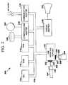
- FIG. 1illustrates a data processing system implementing one embodiment of the present invention using a RS485 data bus
- FIG. 2illustrates a data processing system implementing one embodiment of the present invention using an USB data bus
- FIG. 3illustrates a universal interface connected to a USB host computer
- FIG. 4illustrates a universal interface connected to a RS485 host computer
- FIG. 5illustrates a methodology for implementation of the universal interface
- FIG. 6illustrates a methodology for maintaining a universal interface in a power on logic state.
- USB and RS485are used as the primary example.
- FIG. 1an example is shown of a data processing system 100 which may be used for the invention.
- the systemhas a central processing unit (CPU) 110 .
- the CPU 110is coupled to various other components by system bus 112 .
- Read only memory (“ROM”) 116is coupled to the system bus 112 and includes a basic input/output system (“BIOS”) that controls certain basic functions of the data processing system 100 .
- RAMrandom access memory
- I/O adapter 118may be a small computer system interface (“SCSI”) adapter that communicates with a disk storage device 120 .
- SCSIsmall computer system interface
- Communications adapter 134interconnects bus 112 with an outside network enabling the data processing system to communication with other such systems.
- Input/Output devicesare also connected to system bus 112 via RS485 interface adapter 122 and display adapter 136 .
- Keyboard 124 and mouse 126are interconnected to bus 112 via RS485 interface adapter 122 .
- Keyboard 124is electrically coupled to RS485 interface adapter 122 via a universal interface 130 and plug 131 , cable 146 and port type 135 which is an RS485 port type. Cable 146 is interface specific.
- mouse 126is electrically coupled to RS485 interface adapter via universal interface 128 and plug 129 , cable 145 and port type 141 which is an RS485 port type.
- Cable 145is interface adapter specific. It is important to note that universal interfaces 128 and 130 are physically located on and electrically coupled to their respective peripherals.
- Display monitor 138is connected to system bus 112 by display adapter 136 . In this manner, a user is capable of inputting to the system throughout the keyboard 124 or mouse 126 and receiving output from the system via display 138 .
- FIG. 2an example is shown of a data processing system 200 which may be used for the invention. All components of data processing system 100 are shown in data processing system 200 , with the exception that RS485 interface adapter 122 , and plugs 129 and 131 have been replaced to reflect a USB interface adapter. Therefore, Input/Output devices are connected to system bus 112 via USB interface adapter 222 . Keyboard 124 and mouse 126 are interconnected to bus 112 via USB interface adapter 222 . Keyboard 124 is electrically coupled to USB interface adapter 222 via a universal interface 130 and plug 231 , cable 246 and port type 235 which is an USB port type. Cable 246 is interface adapter specific.
- mouse 126are electrically coupled to USB interface adapter via universal interface 128 and plug 229 , cable 245 and port type 241 which is an USB port type. Cable 245 is interface adapter specific. It is important to note that universal interfaces 128 and 130 are physically located on and electrically coupled to their respective peripherals.
- Universal interface 305is connected to a host 301 computer that operates with a USB bus and is connected to the peripheral device, such as mouse 126 , that will transmit or receive input/output signals via the universal interface 305 to or from the host computer 301 .
- Universal interface 305shows circuitry and firmware that performs the methodology to determine which type of host system the interface 301 is connected thereto and then presents the appropriate data communication interface between the peripheral and the host PC, such that the peripheral may communicate properly with the host PC via the universal interface 305 .
- Universal interface 305includes a microcontroller 310 with both an embedded USB SIE (serial interface engine) and an embedded UART (universal asynchronous receiver transmitter).
- Microcontrollers 310also has general purpose input/output pins.
- An example part for microcontroller 310is Intel 8X930AX.
- Low Dropout Linear Regulator 320provides 3.3 volts for USB. Those familiar with the design and specification of both USB and RS485 buses are familiar with the USB requirement for the 3.3 volts in design while RS485 requires a 5 volt technology.
- Crossbar Switch 330allows connectivity between the peripheral device and the USB host computer when operating in USB mode.
- An example partis Texas Instruments SN74CBT3306 Dual FET Bus Switch.
- RS485 Transceiver 340operates to permit RS485 operations when the universal device is connected to an RS485 host computer.
- An example partis Texas Instruments TL3695.
- CMOS Buffer 350maintains a high impedance on the Connection Detect line 321 . The need for the high impedance on the Connection Detect line 321 will be discussed below.
- An example part of CMOS Buffer 350is Texas Instruments T 1 74HC4050.
- Inverter 360is used in conjunction with RS485 Transceiver and may be any commonly found TTL inverter.
- Resistors RD+ and RD ⁇are resistors which are adjusted from normal values to account for resistance of the Crossbar Switch. This is a fixed adjustment selected by engineering during development. Additionally, the 1.5 K resistor 322 connected between the Low Dropout Linear Regulator 320 and the D+ line 333 is shown for a high speed USB device and thus it and the Connection Detect line 321 are aligned to the D+ line 333 . As those skilled in the art recognize, the present invention can also work for a low speed device by moving the 1.5 K resistor 322 and Connection Detect line 321 to the D ⁇ wiring 334 . Further, as discussed above the invention can be extended such that instead of an RS485, the interface 305 could support any data communication where the bus supports other bus standards known in the art.
- the universal interface 305is in the “power-on” logic state, when plug 303 , which is attached to a USB cable type is coupled to USB host 301 , or when the universal interface 305 is coupled to the host and the host is subsequently powered up.
- the 3.3 volt outputis in a high impedance state.
- the Connection Detect input 321maintains a high impedance state through the operation of CMOS Buffer 350 .
- CMOS Buffer 350operates to ensue the impedance must be high enough so that the Connection Detect line 321 will not have an effect on USB options once proper coupling and USB “start up” sequences have occurred. Further, both Receive Enable 343 and Transmit Enable 344 of the RS485 Transceiver 340 are disabled.
- the Connection Detect line 321senses the coupling by sensing the D+ voltage line 333 . This sensed voltage is read by microprocessor 310 and found to be at a zero logic state. Those familiar with USB operations will understand that this logic state is in accordance with the Universal Serial Bus specification as set forth above.
- the microcontroller 310Upon microcontroller 310 receiving an input at the Connection Detect line 321 of a zero logic state, the microcontroller 310 enables the two-way Crossbar Switch 330 through the Crossbar Control line 335 .
- USB data communicationsmay proceed normally through the universal interface 305 as the connected peripheral transmits or receives data communications through the universal interface 305 to or from the host computer 301 .
- the RS485 Transceiver 340is maintained in a disabled state, maintaining the outputs of the RS485 Transceiver 340 in a high impedance state and thus not affecting the USB operations.
- FIG. 4there is illustrated an example of the universal interface 305 when coupled to a RS485 host computer 401 .
- the universal interface 305is in the “power-on” logic state, when plug 403 , which is attached to a RS485 cable type is coupled to PS485 host 401 , or when the universal interface 305 is coupled to the host and the host is subsequently powered up.
- the component parts for the universal interface 305 described here in FIG. 4are the same as in FIG. 3 except that plug 403 , is attached to a RS485 cable type such as cable 146 in FIG. 1
- the input Connection Detect line 321senses the coupling by sensing the voltage at the coupling and sends that signal to microprocessor 310 . This sensed voltage equates to the logic state of one or a high impedance.
- microprocessor 310detects a logic state of one or a high impedance by way of the Connection Detect line 321 , the two-way Crossbar Logic Switch 330 remains disabled since microcontroller 310 sends no enabling signal to the Crossbar Switch 330 via the Crossbar Control line 335
- microprocessor 310enables RS485 Transceiver 340 .
- a data communications linkis established between the host computer 401 and the peripheral via he universal interface 305 through Transceiver 340 . This allows input and output data communications through the universal interface to or from the host computer 401 to the connected peripheral.
- resistorsare optional pursuant to the RS485 standard.
- point of sale productshave used the 10 K pull up and pull down resistors on the RS485 computer host to prevent oscillation of the RS485 bus output when the host transceiver is not asserted.
- the logic which processes the Connection Detectshould have a method of detecting a high impedance state, for example, a large 300 K pull up resistor.
- the devicemay not be plugged into the RS485 until after the host computer 401 has already started communications, then a sampling technique must be used to search for logic 1 condition of the Connection Detect signal by microprocessor 310 .
- FIG. 5there is illustrated a methodology for selectively determining the host computer's bus characteristics and providing a data communications path via the universal interface for the respective peripheral signals that correspond to the host computer's bus.
- the Interfaceis maintained in a power on logic state at Step 501 .
- a Connection Detect circuitry 321senses the host computer's impedance and determines whether the host computer has a high or low impedance in Step 510 .
- Step 520If the impedance is low, or a logic state of zero as determined in 510 , the two-way Crossbar 330 is enabled in Step 520 , while the RS485 Transceiver 340 is maintained in a disabled state in Step 530 .
- Step 540the peripheral device is “connected” in Step 540 via the universal interface in accordance with USB specifications. Once “connected” the peripheral device will operate with the host computer within USB specifications as shown in the Step 550 .
- Step 510the impedance state is high or logic state of one, then the two-way crossbar circuitry is maintained in a disabled state in Step 560 .
- RS485 Transceiveris enabled in Step 570 which allows the RS485 operations to proceed as normal in Step 580 .
- FIG. 6illustrates a methodology for establishing a universal interface prior to connection.
- 501 's initial conditionsare described in FIG. 1 .
- Step 601starts the process.
- the Connection Detect 321 input impedanceis maintained in a high state in Step 610 .
- the Crossbar Control switch 335is disabled in Step 620 and the RS485 Transceiver 340 maintains the Receive Enable 343 in disabled state in Step 630 and the Transmit Enable 344 disabled in Step 640 .
Landscapes
- Engineering & Computer Science (AREA)
- Theoretical Computer Science (AREA)
- General Engineering & Computer Science (AREA)
- Physics & Mathematics (AREA)
- General Physics & Mathematics (AREA)
- Computer Hardware Design (AREA)
- Information Transfer Systems (AREA)
Abstract
Description
The present application is related to copending U.S. patent application Ser. No. 09/510,947, which is hereby incorporated by reference herein.
The present invention relates to a universal interface for coupling to a host computer port type of a host computer system.
Personal computers (“PCs”) use a variety of techniques for providing input and output via peripheral devices. In the past, the PCs have included a serial port, usually an RS232 or RS485, and a parallel port in several ISA expansion slots included on the motherboard. Connecting the PCs to anything more complicated than a mouse, modem or printer usually required the lid to be taken off the PC, dip switches to be set, and software configured. A SCSI (small computer systems interface) device permitted access to external storage devices, but required a large cable connector with the need to manually set ID numbers and have a terminal.
The universal serial bus (“USB”) is specified to be a new industry standard extension to the PC architecture with a focus on computer telephony interface, consumer and productivity applications. The USB architecture provides for ease of use for peripheral expansion, transfer rates up to twelve megabits per second, protocol flexibility for mixed modes, isochronous data transfers, and asynchronous messaging and has begun to replace earlier generational serial interfaces such as RS485. USB is a cable bus supporting data transfer between the host PC and a range of simultaneously operable peripherals. One host controller can support up to 127 physical devices using a tiered star topology. The hub is at the center of each star with each wire segment creating a point-to-point connection of up to five meters. The five meter limitation may be between a host and hub or a hub function or a hub connected to another hub or function.
As the point of sale industry begins the transition to USB architecture instead of legacy RS232 or RS485 or other custom interfaces, a problem exists because manufacturers need to produce two sets of similar peripheral devices—one device for use with a PC with USB architecture, and a second, similar device for use with a host computer with RS485 architecture. Therefore, equipment suppliers are faced with manufacturing two sets of similar products that will be sold and co-exist in the field for some period of time after the introduction of USB.
Thus, a need exists in the art where one device or peripheral can be sold so that it may be operably connected to a host computer having either a USB or RS485 or other serial bus capabilities. This unresolved problem and deficiency is clearly felt in the art and is solved by the invention in the manner described below.
The foregoing need is addressed by the present invention which provides an universal interface, electrically connected to a peripheral device, comprising a first or a second cable type for coupling the universal interface to a host computer, circuitry for sensing a voltage presented at the first or second port type, and circuitry for establishing a first or second data communications link between the host computer and the peripheral device via the universal interface in response to the voltage sensed.
Additionally, the present invention provides a data processing system comprising a host computer with either a first or second communications bus, a universal interface coupled to a first or second port type of the host computer, circuitry for determining a first or second voltage at the respective port, and circuitry for establishing the proper data communications path between the host computer, universal interface and peripheral device connected thereto.
Finally, the present invention provides a methodology for selectively enabling one of two interface logic circuits when a universal interface is coupled to a host computer.
The foregoing has outlined rather broadly the features and technical advantages of the present invention in order that the detailed description of the invention that follows may be better understood. Additional features and advantages of the invention will be described hereinafter which form the subject of the claims of the invention.
For a more complete understanding of the present invention, and the advantages thereof, reference is now made to the following descriptions taken in conjunction with the accompanying drawings, in which:
FIG. 1 illustrates a data processing system implementing one embodiment of the present invention using a RS485 data bus;
FIG. 2 illustrates a data processing system implementing one embodiment of the present invention using an USB data bus;
FIG. 3 illustrates a universal interface connected to a USB host computer;
FIG. 4 illustrates a universal interface connected to a RS485 host computer;
FIG. 5 illustrates a methodology for implementation of the universal interface; and
FIG. 6 illustrates a methodology for maintaining a universal interface in a power on logic state.
In the following description, numerous specific details are set forth such as specific voltages and currents to provide a thorough understanding of the present invention. However, it will be obvious to those skilled in the art that the present invention may be practiced without such specific details. In other instances, well-known circuits have been shown in block diagram form in order not to obscure the present invention in unnecessary detail. For the most part, details concerning timing considerations and the like have been omitted inasmuch as such details are not necessary to obtain a complete understanding of the present invention and are within the skills of persons of ordinary skill in the relevant art.
Refer now to the drawings wherein depicted elements are not necessarily shown to scale and wherein like or similar elements are designated by the same reference numeral through the several views.
Within the following description, a standard USB connector, receptacle, plug and signaling all refer to the USB architecture described within the “Universal Serial Bus Specification,” Revision 1.1 Copyright Sep. 23, 1998 which is hereby incorporated by reference herein. While an embodiment of the invention will be illustrated using the USB or RS485 host system with just a change of cable to fit the respective form factors of the USB or RS485 connectors, those skilled in the art will understand that several of the concepts of the disclosure could be extended to create devices capable of working with other sets of interfaces as well, such as USB/ RS232 or USB/ PS-2 mouse. For the purposes of demonstrating the embodiment described below, USB and RS485 are used as the primary example.
Referring first to FIG. 1, an example is shown of adata processing system 100 which may be used for the invention. The system has a central processing unit (CPU)110. TheCPU 110 is coupled to various other components bysystem bus 112. Read only memory (“ROM”)116 is coupled to thesystem bus 112 and includes a basic input/output system (“BIOS”) that controls certain basic functions of thedata processing system 100. Random access memory (“RAM”)114, I/O adapter 118, andcommunications adapter 134 are also coupled to thesystem bus 112. I/O adapter 118 may be a small computer system interface (“SCSI”) adapter that communicates with adisk storage device 120. Communications adapter134interconnects bus 112 with an outside network enabling the data processing system to communication with other such systems. Input/Output devices are also connected tosystem bus 112 via RS485interface adapter 122 anddisplay adapter 136. Keyboard124 andmouse 126 are interconnected tobus 112 via RS485interface adapter 122. Keyboard124 is electrically coupled to RS485interface adapter 122 via auniversal interface 130 andplug 131,cable 146 andport type 135 which is an RS485 port type. Cable146 is interface specific. Likewise,mouse 126 is electrically coupled to RS485 interface adapter viauniversal interface 128 andplug 129,cable 145 andport type 141 which is an RS485 port type. Cable145 is interface adapter specific. It is important to note thatuniversal interfaces Display monitor 138 is connected tosystem bus 112 bydisplay adapter 136. In this manner, a user is capable of inputting to the system throughout thekeyboard 124 ormouse 126 and receiving output from the system viadisplay 138.
Referring to FIG. 2, an example is shown of adata processing system 200 which may be used for the invention. All components ofdata processing system 100 are shown indata processing system 200, with the exception that RS485interface adapter 122, andplugs system bus 112 via USB interface adapter222. Keyboard124 andmouse 126 are interconnected tobus 112 via USB interface adapter222. Keyboard124 is electrically coupled to USB interface adapter222 via auniversal interface 130 andplug 231,cable 246 andport type 235 which is an USB port type. Cable246 is interface adapter specific. Likewise,mouse 126 are electrically coupled to USB interface adapter viauniversal interface 128 and plug229,cable 245 andport type 241 which is an USB port type.Cable 245 is interface adapter specific. It is important to note thatuniversal interfaces
Referring to FIG. 3, there is illustrated one embodiment of the present invention.Universal interface 305 is connected to ahost 301 computer that operates with a USB bus and is connected to the peripheral device, such asmouse 126, that will transmit or receive input/output signals via theuniversal interface 305 to or from thehost computer 301.Universal interface 305 shows circuitry and firmware that performs the methodology to determine which type of host system theinterface 301 is connected thereto and then presents the appropriate data communication interface between the peripheral and the host PC, such that the peripheral may communicate properly with the host PC via theuniversal interface 305.
Theuniversal interface 305 is in the “power-on” logic state, whenplug 303, which is attached to a USB cable type is coupled toUSB host 301, or when theuniversal interface 305 is coupled to the host and the host is subsequently powered up. The 3.3 volt output is in a high impedance state. Also, the Connection Detectinput 321 maintains a high impedance state through the operation ofCMOS Buffer 350.CMOS Buffer 350 operates to ensue the impedance must be high enough so that the Connection Detectline 321 will not have an effect on USB options once proper coupling and USB “start up” sequences have occurred. Further, both ReceiveEnable 343 and TransmitEnable 344 of theRS485 Transceiver 340 are disabled. Therefore, the outputs of theRS485 Transceiver 340 are in a high impedance state. Finally, the two-wayCrossbar Logic Switch 330 controlling distribution of D+333 and D−334 to the USB serial engine located inhost computer 301 is disabled in both directions.
Upon connection of theuniversal interface 305 to thehost computer 301 whenplug 303 is coupled to the USB host computer port302, the Connection Detectline 321 senses the coupling by sensing theD+ voltage line 333. This sensed voltage is read bymicroprocessor 310 and found to be at a zero logic state. Those familiar with USB operations will understand that this logic state is in accordance with the Universal Serial Bus specification as set forth above. Uponmicrocontroller 310 receiving an input at the Connection Detectline 321 of a zero logic state, themicrocontroller 310 enables the two-way Crossbar Switch 330 through theCrossbar Control line 335. This allows the USB device to become “connected.” Once the USB interface becomes “connected,” a data communications link is established between thehost computer 301 and the peripheral device via theuniversal interface 305. USB data communications may proceed normally through theuniversal interface 305 as the connected peripheral transmits or receives data communications through theuniversal interface 305 to or from thehost computer 301. During the entire startup connection to the USB host, theRS485 Transceiver 340 is maintained in a disabled state, maintaining the outputs of theRS485 Transceiver 340 in a high impedance state and thus not affecting the USB operations.
Referring now to FIG. 4, there is illustrated an example of theuniversal interface 305 when coupled to aRS485 host computer 401. Theuniversal interface 305 is in the “power-on” logic state, whenplug 403, which is attached to a RS485 cable type is coupled toPS485 host 401, or when theuniversal interface 305 is coupled to the host and the host is subsequently powered up. The component parts for theuniversal interface 305 described here in FIG. 4 are the same as in FIG. 3 except thatplug 403, is attached to a RS485 cable type such ascable 146 in FIG. 1
Upon coupling thehost computer 401 having an RS485 bus via the host computer port402 and theuniversal interface 305 throughplug 403, the input Connection Detectline 321 senses the coupling by sensing the voltage at the coupling and sends that signal tomicroprocessor 310. This sensed voltage equates to the logic state of one or a high impedance. Whenmicroprocessor 310 detects a logic state of one or a high impedance by way of the Connection Detectline 321, the two-wayCrossbar Logic Switch 330 remains disabled sincemicrocontroller 310 sends no enabling signal to theCrossbar Switch 330 via theCrossbar Control line 335 Next,microprocessor 310 enablesRS485 Transceiver 340. Thus, a data communications link is established between thehost computer 401 and the peripheral via heuniversal interface 305 throughTransceiver 340. This allows input and output data communications through the universal interface to or from thehost computer 401 to the connected peripheral.
It is important to note that while typical resistor values are shown for aRS485 host computer 401, the resistors are optional pursuant to the RS485 standard. Previously, point of sale products have used the 10 K pull up and pull down resistors on the RS485 computer host to prevent oscillation of the RS485 bus output when the host transceiver is not asserted. For an operation on hosts which might not have the optional 10 K pull up/pull down resistors, those skilled in the art will understand that the logic which processes the Connection Detect should have a method of detecting a high impedance state, for example, a large 300 K pull up resistor. If due to timing restrictions or hot plugging applications, the device may not be plugged into the RS485 until after thehost computer 401 has already started communications, then a sampling technique must be used to search forlogic 1 condition of the Connection Detect signal bymicroprocessor 310.
Referring now to FIG. 5, there is illustrated a methodology for selectively determining the host computer's bus characteristics and providing a data communications path via the universal interface for the respective peripheral signals that correspond to the host computer's bus. According to this methodology, immediately after power is applied, the Interface is maintained in a power on logic state atStep 501. Upon coupling the device to a host computer inStep 505, a Connection Detectcircuitry 321 senses the host computer's impedance and determines whether the host computer has a high or low impedance inStep 510. If the impedance is low, or a logic state of zero as determined in510, the two-way Crossbar 330 is enabled inStep 520, while theRS485 Transceiver 340 is maintained in a disabled state inStep 530. This provides that the peripheral device is “connected” inStep 540 via the universal interface in accordance with USB specifications. Once “connected” the peripheral device will operate with the host computer within USB specifications as shown in theStep 550. If inStep 510, the impedance state is high or logic state of one, then the two-way crossbar circuitry is maintained in a disabled state inStep 560. RS485 Transceiver is enabled inStep 570 which allows the RS485 operations to proceed as normal inStep 580.
FIG. 6 illustrates a methodology for establishing a universal interface prior to connection.501's initial conditions are described in FIG.1. Step601 starts the process. First, the Connection Detect321 input impedance is maintained in a high state inStep 610. TheCrossbar Control switch 335 is disabled inStep 620 and theRS485 Transceiver 340 maintains the ReceiveEnable 343 in disabled state inStep 630 and the TransmitEnable 344 disabled inStep 640.
While the invention has been described in detail herein, in accordance with certain embodiments thereof, modifications and changes therein may be affected by those skilled in the art. Accordingly, it is intended by the appended claims to cover all such modifications and changes as fall within the true spirit and scope of the intention.
Although the present invention and its advantages have been described in detail, it should be understood that various changes, substitutions and alterations can be made herein without departing from the spirit and scope of the invention as defined by the appended claims.
Claims (7)
1. A universal interface comprising:
a microcontroller;
a detection line coupled to said microcontroller, wherein said detection line is configured to sense a voltage at a port of a host computer coupled to said universal interface;
a crossbar switch coupled to said microcontroller, wherein said crossbar switch is configured to establish a data communication link between said universal interface and a first type port of said host computer, wherein said crossbar switch is enabled to establish said data communication link between said universal interface and said first type port of said host computer upon said detection line sensing a first logic state; and
a transceiver coupled to said microcontroller, wherein said transceiver is configured to establish a data communication link between said universal interface and a second type port of said host computer, wherein said transceiver is enabled to establish said data communication link between said universal interface and said second type port of said host computer upon said detection line sensing a second logic state.
2. The universal interface as recited inclaim 1 , wherein said first type port is electrically coupled to a universal serial bus.
3. The universal interface as recited inclaim 1 , wherein said second type port is electrically coupled to a non-universal serial bus.
4. The universal interface as recited inclaim 1 , wherein said first logic state is a logic slate of zero.
5. The universal interface as recited inclaim 1 , wherein said second logic state is a logic state of non-zero.
6. The universal interface as recited inclaim 1 , wherein said universal interface physically resides within a physical embodiment of a peripheral device.
7. The universal interface as recited inclaim 6 , wherein said peripheral device is a mouse.
Priority Applications (1)
| Application Number | Priority Date | Filing Date | Title |
|---|---|---|---|
| US09/503,315US6601124B1 (en) | 2000-02-14 | 2000-02-14 | Universal interface for selectively coupling to a computer port type and method therefor |
Applications Claiming Priority (1)
| Application Number | Priority Date | Filing Date | Title |
|---|---|---|---|
| US09/503,315US6601124B1 (en) | 2000-02-14 | 2000-02-14 | Universal interface for selectively coupling to a computer port type and method therefor |
Publications (1)
| Publication Number | Publication Date |
|---|---|
| US6601124B1true US6601124B1 (en) | 2003-07-29 |
Family
ID=27613640
Family Applications (1)
| Application Number | Title | Priority Date | Filing Date |
|---|---|---|---|
| US09/503,315Expired - LifetimeUS6601124B1 (en) | 2000-02-14 | 2000-02-14 | Universal interface for selectively coupling to a computer port type and method therefor |
Country Status (1)
| Country | Link |
|---|---|
| US (1) | US6601124B1 (en) |
Cited By (47)
| Publication number | Priority date | Publication date | Assignee | Title |
|---|---|---|---|---|
| US20020143996A1 (en)* | 2001-03-29 | 2002-10-03 | Vic Odryna | Passive video multiplexing method and apparatus priority to prior provisional application |
| US20030041203A1 (en)* | 2000-07-06 | 2003-02-27 | Onspec Electronic, Inc. | Flashtoaster for reading several types of flash-memory cards with or without a PC |
| US20030115400A1 (en)* | 2001-12-13 | 2003-06-19 | Fuji Xerox Co., Ltd. | Interface apparatus |
| US20030126340A1 (en)* | 2001-12-27 | 2003-07-03 | Kazunobu Toguchi | Method to prevent net update oscillation |
| US20030135655A1 (en)* | 2002-01-16 | 2003-07-17 | Yen-Chang Chiu | Apparatus and method for automatically identifying between USB and PS/2 interface |
| US20030158977A1 (en)* | 2000-08-30 | 2003-08-21 | Jens Barrenscheen | Identification of a peripheral connection state with a universal serial bus |
| US20030208652A1 (en)* | 2002-05-02 | 2003-11-06 | International Business Machines Corporation | Universal network interface connection |
| US20030233507A1 (en)* | 2002-06-13 | 2003-12-18 | C-One Technology Corporation | Electronic card with multiple interfaces |
| US20030236937A1 (en)* | 2002-06-21 | 2003-12-25 | Marcelo Barros De Almeida | Plug and play reconfigurable USB interface for industrial fieldbus network access |
| US6721810B2 (en)* | 2000-08-31 | 2004-04-13 | Siemens Energy & Automation | Universal controller expansion module system, method and apparatus |
| WO2004040546A1 (en)* | 2002-10-04 | 2004-05-13 | Onspec Electronic, Inc. | Integrated virtual hub chip |
| EP1533682A1 (en)* | 2003-11-21 | 2005-05-25 | Research In Motion Limited | System and method for powering a peripheral device |
| US20050132115A1 (en)* | 1999-06-10 | 2005-06-16 | Leach Mark A. | Host-client utility meter systems and methods for communicating with the same |
| US20050154799A1 (en)* | 2004-01-08 | 2005-07-14 | Uis Abler Electronics Co., Ltd. | Switching device for RS-232 serial port and USB serial port |
| US20060036795A1 (en)* | 2000-06-09 | 2006-02-16 | Mark Leach | Method and system for monitoring and transmitting utility status via universal communications interface |
| US20060095643A1 (en)* | 2004-10-28 | 2006-05-04 | Tsutomu Baba | Slave device in information processing system, operation control program for slave device, and operation control method for slave device |
| WO2006064142A1 (en)* | 2004-12-15 | 2006-06-22 | Viamichelin | Interface device |
| WO2006133308A1 (en)* | 2005-06-08 | 2006-12-14 | Fisher-Rosemount Systems, Inc. | Multi-protocol field device interface with automatic bus detection |
| US20070016715A1 (en)* | 2005-07-18 | 2007-01-18 | Quintech Electronics & Commuications, Inc. | Modular broadband bi-directional programmable switch with hot-swappable modules |
| CN1308794C (en)* | 2004-10-26 | 2007-04-04 | 威盛电子股份有限公司 | USB power-saving control circuit and method |
| US20070130408A1 (en)* | 2000-06-09 | 2007-06-07 | Universal Smart Technologies, Llc | Host-Client Utility Meter Systems And Methods For Communicating With The Same |
| EP1804152A3 (en)* | 2003-11-21 | 2007-07-11 | Research In Motion Limited | System and method for powering a peripheral device |
| US20070174526A1 (en)* | 2005-04-29 | 2007-07-26 | Avocent Corporation | Virtual media systems, methods and devices |
| US20080017718A1 (en)* | 2000-07-06 | 2008-01-24 | Onspec Electronic, Inc. | Memory Module Which Includes a Form Factor Connector |
| US7493437B1 (en) | 2000-07-06 | 2009-02-17 | Mcm Portfolio Llc | Flashtoaster for reading several types of flash memory cards with or without a PC |
| CN100477412C (en)* | 2004-09-10 | 2009-04-08 | 联发科技股份有限公司 | Multi-device connection system and method thereof |
| US7577482B1 (en) | 2007-03-08 | 2009-08-18 | The United States Of America As Represented By The Administrator Of The National Aeronautics And Space Administration | System comprising interchangeable electronic controllers and corresponding methods |
| US7620844B2 (en) | 2000-07-06 | 2009-11-17 | Mcm Portfolio Llc | Field-operable, stand-alone apparatus for media recovery and regeneration |
| US20100013325A1 (en)* | 2008-07-15 | 2010-01-21 | Vande Vusse Daniel E | Field device interface with network protection mechanism |
| US7719847B2 (en) | 2000-07-06 | 2010-05-18 | Mcm Portfolio Llc | Smartconnect flash card adapter |
| US8009173B2 (en) | 2006-08-10 | 2011-08-30 | Avocent Huntsville Corporation | Rack interface pod with intelligent platform control |
| CN102446153A (en)* | 2011-12-15 | 2012-05-09 | 张国星 | Communication module based on NLAS323 chip |
| US8269783B2 (en) | 1999-08-25 | 2012-09-18 | Avocent Redmond Corporation | KVM switch including a terminal emulator |
| US8427489B2 (en) | 2006-08-10 | 2013-04-23 | Avocent Huntsville Corporation | Rack interface pod with intelligent platform control |
| US20130227185A1 (en)* | 2010-10-04 | 2013-08-29 | Avocent Huntsville Corp. | Remote access appliance with communication protocol autosensing feature |
| US8621129B2 (en)* | 2010-12-09 | 2013-12-31 | Intel Corporation | Method and apparatus to reduce serial bus transmission power |
| CN104077255A (en)* | 2013-12-29 | 2014-10-01 | 国家电网公司 | Method for terminal to communicate with computer through USB |
| US20160182640A1 (en)* | 2013-07-26 | 2016-06-23 | Thermo King Corporation | Method and system for controlling the collection and storage of data in a transport refrigeration system |
| US9543919B2 (en)* | 2011-10-24 | 2017-01-10 | Skyworks Solutions, Inc. | Dual mode power amplifier control interface with a multi-mode general purpose input/output interface |
| CN107273320A (en)* | 2016-04-08 | 2017-10-20 | 中兴通讯股份有限公司 | A kind of adaptive multiplexer of communication interface hardware and method |
| US9946682B2 (en) | 2013-01-28 | 2018-04-17 | Hewlett-Packard Development Company, L.P. | Detecting device installation and removal on a port |
| US20180143926A1 (en)* | 2015-04-27 | 2018-05-24 | Karin KLOOSTERMAN | Universal conversion system and a method for improving the mode of action of the same |
| CN109117400A (en)* | 2018-08-09 | 2019-01-01 | 深圳市宏电技术股份有限公司 | A kind of interface automatic switching control equipment and method |
| US10451664B2 (en)* | 2013-03-13 | 2019-10-22 | Schumacher Electric Corporation | Interconnect device for detecting whether a vehicle on-board diagnostics (OBD) data port includes circuitry which prevents back feeding of power through the OBD data port |
| US20220067163A1 (en)* | 2020-08-28 | 2022-03-03 | Coretronic Corporation | Electronic-device control system and electronic-device control method |
| US11451199B2 (en) | 2012-06-14 | 2022-09-20 | Skyworks Solutions, Inc. | Power amplifier systems with control interface and bias circuit |
| US11984423B2 (en) | 2011-09-02 | 2024-05-14 | Skyworks Solutions, Inc. | Radio frequency transmission line with finish plating on conductive layer |
Citations (19)
| Publication number | Priority date | Publication date | Assignee | Title |
|---|---|---|---|---|
| US5457784A (en)* | 1992-03-05 | 1995-10-10 | Metacomp, Inc. | Interfacing system using an auto-adapting multi-ported control module between an i/o port and a plurality of peripheral adaptors via bus extending cables |
| US5734334A (en) | 1991-10-30 | 1998-03-31 | I-Cube, Inc. | Programmable port for crossbar switch |
| US5832244A (en)* | 1996-02-20 | 1998-11-03 | Iomega Corporation | Multiple interface input/output port for a peripheral device |
| US5841424A (en) | 1997-03-03 | 1998-11-24 | Lextron Systems, Inc. | USB to multiple connect and support bays for peripheral devices |
| US5859985A (en) | 1996-01-14 | 1999-01-12 | At&T Wireless Services, Inc. | Arbitration controller for providing arbitration on a multipoint high speed serial bus using drivers having output enable pins |
| US5884086A (en) | 1997-04-15 | 1999-03-16 | International Business Machines Corporation | System and method for voltage switching to supply various voltages and power levels to a peripheral device |
| US5896534A (en) | 1996-01-26 | 1999-04-20 | Dell Usa, L.P. | Operating system independent apparatus and method for supporting input/output devices unsupported by executing programs |
| US5920734A (en)* | 1996-02-01 | 1999-07-06 | Microsoft Corporation | System for providing electrical power to a computer input device according to the interface types through the shared use of wires and a voltage clamp |
| US5930496A (en) | 1997-09-26 | 1999-07-27 | Compaq Computer Corporation | Computer expansion slot and associated logic for automatically detecting compatibility with an expansion card |
| US5933656A (en) | 1997-06-18 | 1999-08-03 | Raytheon Company | System for interfacing host computer to multiple peripheral devices using daisy-chainable bus and federated computational input/output circuit card assemblies |
| US5938770A (en) | 1996-07-19 | 1999-08-17 | Samsung Electronics Co., Ltd. | Display apparatus for computer system |
| WO1999066415A1 (en) | 1998-06-19 | 1999-12-23 | Gateway | Communication system and method for interfacing differing communication standards |
| US6038630A (en) | 1998-03-24 | 2000-03-14 | International Business Machines Corporation | Shared access control device for integrated system with multiple functional units accessing external structures over multiple data buses |
| US6058441A (en)* | 1998-02-19 | 2000-05-02 | Shu; Han | USB multi-function connecting device |
| US6088754A (en)* | 1997-12-31 | 2000-07-11 | Cisco Technology, Inc. | Generic serial interface with automatic reconfigurability |
| US6247075B1 (en)* | 1998-06-24 | 2001-06-12 | Primax Electronics Ltd. | Mouse interface converter for connecting mouse to computers with different types of connecting ports |
| US6260084B1 (en)* | 1998-05-18 | 2001-07-10 | 3Com Corporation | Modem apparatus and method for serial command and data multiplexing |
| US20010016890A1 (en)* | 2000-02-07 | 2001-08-23 | Alps Electric Co., Ltd. | Interface distinguishing apparatus |
| US20010034807A1 (en)* | 2000-04-25 | 2001-10-25 | Kabushiki Kaisha | Mobile communication terminal device |
- 2000
- 2000-02-14USUS09/503,315patent/US6601124B1/ennot_activeExpired - Lifetime
Patent Citations (19)
| Publication number | Priority date | Publication date | Assignee | Title |
|---|---|---|---|---|
| US5734334A (en) | 1991-10-30 | 1998-03-31 | I-Cube, Inc. | Programmable port for crossbar switch |
| US5457784A (en)* | 1992-03-05 | 1995-10-10 | Metacomp, Inc. | Interfacing system using an auto-adapting multi-ported control module between an i/o port and a plurality of peripheral adaptors via bus extending cables |
| US5859985A (en) | 1996-01-14 | 1999-01-12 | At&T Wireless Services, Inc. | Arbitration controller for providing arbitration on a multipoint high speed serial bus using drivers having output enable pins |
| US5896534A (en) | 1996-01-26 | 1999-04-20 | Dell Usa, L.P. | Operating system independent apparatus and method for supporting input/output devices unsupported by executing programs |
| US5920734A (en)* | 1996-02-01 | 1999-07-06 | Microsoft Corporation | System for providing electrical power to a computer input device according to the interface types through the shared use of wires and a voltage clamp |
| US5832244A (en)* | 1996-02-20 | 1998-11-03 | Iomega Corporation | Multiple interface input/output port for a peripheral device |
| US5938770A (en) | 1996-07-19 | 1999-08-17 | Samsung Electronics Co., Ltd. | Display apparatus for computer system |
| US5841424A (en) | 1997-03-03 | 1998-11-24 | Lextron Systems, Inc. | USB to multiple connect and support bays for peripheral devices |
| US5884086A (en) | 1997-04-15 | 1999-03-16 | International Business Machines Corporation | System and method for voltage switching to supply various voltages and power levels to a peripheral device |
| US5933656A (en) | 1997-06-18 | 1999-08-03 | Raytheon Company | System for interfacing host computer to multiple peripheral devices using daisy-chainable bus and federated computational input/output circuit card assemblies |
| US5930496A (en) | 1997-09-26 | 1999-07-27 | Compaq Computer Corporation | Computer expansion slot and associated logic for automatically detecting compatibility with an expansion card |
| US6088754A (en)* | 1997-12-31 | 2000-07-11 | Cisco Technology, Inc. | Generic serial interface with automatic reconfigurability |
| US6058441A (en)* | 1998-02-19 | 2000-05-02 | Shu; Han | USB multi-function connecting device |
| US6038630A (en) | 1998-03-24 | 2000-03-14 | International Business Machines Corporation | Shared access control device for integrated system with multiple functional units accessing external structures over multiple data buses |
| US6260084B1 (en)* | 1998-05-18 | 2001-07-10 | 3Com Corporation | Modem apparatus and method for serial command and data multiplexing |
| WO1999066415A1 (en) | 1998-06-19 | 1999-12-23 | Gateway | Communication system and method for interfacing differing communication standards |
| US6247075B1 (en)* | 1998-06-24 | 2001-06-12 | Primax Electronics Ltd. | Mouse interface converter for connecting mouse to computers with different types of connecting ports |
| US20010016890A1 (en)* | 2000-02-07 | 2001-08-23 | Alps Electric Co., Ltd. | Interface distinguishing apparatus |
| US20010034807A1 (en)* | 2000-04-25 | 2001-10-25 | Kabushiki Kaisha | Mobile communication terminal device |
Non-Patent Citations (1)
| Title |
|---|
| Universal Serial Bus Specification, Revision 1.1, Copyright Sep. 23, 1998. |
Cited By (95)
| Publication number | Priority date | Publication date | Assignee | Title |
|---|---|---|---|---|
| US7185131B2 (en)* | 1999-06-10 | 2007-02-27 | Amron Technologies, Inc. | Host-client utility meter systems and methods for communicating with the same |
| US20070210933A1 (en)* | 1999-06-10 | 2007-09-13 | Universal Smart Technologies, Llc | Systems and Methods For Monitoring and Transmitting Utility Status Information Via A Universal Communications Interface |
| US20050132115A1 (en)* | 1999-06-10 | 2005-06-16 | Leach Mark A. | Host-client utility meter systems and methods for communicating with the same |
| US8269783B2 (en) | 1999-08-25 | 2012-09-18 | Avocent Redmond Corporation | KVM switch including a terminal emulator |
| US20070130408A1 (en)* | 2000-06-09 | 2007-06-07 | Universal Smart Technologies, Llc | Host-Client Utility Meter Systems And Methods For Communicating With The Same |
| US7231482B2 (en) | 2000-06-09 | 2007-06-12 | Universal Smart Technologies, Llc. | Method and system for monitoring and transmitting utility status via universal communications interface |
| US20060036795A1 (en)* | 2000-06-09 | 2006-02-16 | Mark Leach | Method and system for monitoring and transmitting utility status via universal communications interface |
| US7487282B2 (en) | 2000-06-09 | 2009-02-03 | Leach Mark A | Host-client utility meter systems and methods for communicating with the same |
| US7493437B1 (en) | 2000-07-06 | 2009-02-17 | Mcm Portfolio Llc | Flashtoaster for reading several types of flash memory cards with or without a PC |
| US8011964B2 (en) | 2000-07-06 | 2011-09-06 | Mcm Portfolio Llc | Smartconnect flash card adapter |
| US7620844B2 (en) | 2000-07-06 | 2009-11-17 | Mcm Portfolio Llc | Field-operable, stand-alone apparatus for media recovery and regeneration |
| US7597268B2 (en) | 2000-07-06 | 2009-10-06 | Mcm Portfolio Llc | Memory module which includes a form factor connector |
| US7222205B2 (en) | 2000-07-06 | 2007-05-22 | Onspec Electronic, Inc. | Flashtoaster for reading several types of flash-memory cards with or without a PC |
| US20030041203A1 (en)* | 2000-07-06 | 2003-02-27 | Onspec Electronic, Inc. | Flashtoaster for reading several types of flash-memory cards with or without a PC |
| US7719847B2 (en) | 2000-07-06 | 2010-05-18 | Mcm Portfolio Llc | Smartconnect flash card adapter |
| US20100195290A1 (en)* | 2000-07-06 | 2010-08-05 | Mcm Portfolio Llc | Smartconnect Flash Card Adapter |
| US20080250174A1 (en)* | 2000-07-06 | 2008-10-09 | Mcm Portfolio Llc. | Flashtoaster for Reading Several Types of Flash-Memory Cards, With or Without a PC |
| US20060253636A1 (en)* | 2000-07-06 | 2006-11-09 | Onspec Electronic, Inc. | Flash toaster for reading several types of flash memory cards with or without a PC |
| US7412552B2 (en) | 2000-07-06 | 2008-08-12 | Mcm Portfolio Llc | Flashtoaster for reading several types of flash-memory cards, with or without a PC |
| US9558135B2 (en)* | 2000-07-06 | 2017-01-31 | Larry Lawson Jones | Flashcard reader and converter for reading serial and parallel flashcards |
| US20080017718A1 (en)* | 2000-07-06 | 2008-01-24 | Onspec Electronic, Inc. | Memory Module Which Includes a Form Factor Connector |
| US8337252B2 (en) | 2000-07-06 | 2012-12-25 | Mcm Portfolio Llc | Smartconnect flash card adapter |
| US20070283069A1 (en)* | 2000-07-06 | 2007-12-06 | Technology Properties Limited | Flashtoaster for Reading Several Types of Flash-Memory Cards, With or Without a PC |
| US20030158977A1 (en)* | 2000-08-30 | 2003-08-21 | Jens Barrenscheen | Identification of a peripheral connection state with a universal serial bus |
| US6854024B2 (en)* | 2000-08-30 | 2005-02-08 | Infineon Technologies Ag | Identification of a peripheral connection state with a universal serial bus |
| US6721810B2 (en)* | 2000-08-31 | 2004-04-13 | Siemens Energy & Automation | Universal controller expansion module system, method and apparatus |
| US20020143996A1 (en)* | 2001-03-29 | 2002-10-03 | Vic Odryna | Passive video multiplexing method and apparatus priority to prior provisional application |
| US20050204082A1 (en)* | 2001-03-29 | 2005-09-15 | Avocent Corporation | Computer interface module |
| US7424551B2 (en) | 2001-03-29 | 2008-09-09 | Avocent Corporation | Passive video multiplexing method and apparatus priority to prior provisional application |
| US7590763B2 (en)* | 2001-03-29 | 2009-09-15 | Avocent Corporation | Device for use in a system for processing keyboard, video and mouse signals |
| US7010640B2 (en)* | 2001-12-13 | 2006-03-07 | Fuji Xerox Co., Ltd. | Interface apparatus for mediating sending and receiving signals between devices connected by a signal line |
| US20030115400A1 (en)* | 2001-12-13 | 2003-06-19 | Fuji Xerox Co., Ltd. | Interface apparatus |
| US6898658B2 (en)* | 2001-12-27 | 2005-05-24 | Koninklijke Philips Electronics N.V. | Method to prevent net update oscillation |
| US20030126340A1 (en)* | 2001-12-27 | 2003-07-03 | Kazunobu Toguchi | Method to prevent net update oscillation |
| US6886052B2 (en)* | 2002-01-16 | 2005-04-26 | Elan Microelectronics Corporation | Apparatus and method for automatically identifying between USB and PS/2 interface |
| US20030135655A1 (en)* | 2002-01-16 | 2003-07-17 | Yen-Chang Chiu | Apparatus and method for automatically identifying between USB and PS/2 interface |
| US20030208652A1 (en)* | 2002-05-02 | 2003-11-06 | International Business Machines Corporation | Universal network interface connection |
| US7171505B2 (en)* | 2002-05-02 | 2007-01-30 | International Business Machines Corporation | Universal network interface connection |
| US20030233507A1 (en)* | 2002-06-13 | 2003-12-18 | C-One Technology Corporation | Electronic card with multiple interfaces |
| US20030236937A1 (en)* | 2002-06-21 | 2003-12-25 | Marcelo Barros De Almeida | Plug and play reconfigurable USB interface for industrial fieldbus network access |
| US6839790B2 (en)* | 2002-06-21 | 2005-01-04 | Smar Research Corporation | Plug and play reconfigurable USB interface for industrial fieldbus network access |
| US20050083305A1 (en)* | 2002-10-04 | 2005-04-21 | Sreenath Mambakkam | Integrated virtual hub chip |
| US7352362B2 (en) | 2002-10-04 | 2008-04-01 | Mcm Portfolio Llc | Integrated virtual hub chip |
| US20080133804A1 (en)* | 2002-10-04 | 2008-06-05 | Mcm Portfolio Llc | Integrated Virtual Hub Chip |
| US20050216622A1 (en)* | 2002-10-04 | 2005-09-29 | Iyer Sree M | Integrated virtual hub chip |
| WO2004040546A1 (en)* | 2002-10-04 | 2004-05-13 | Onspec Electronic, Inc. | Integrated virtual hub chip |
| US6903727B2 (en)* | 2002-10-04 | 2005-06-07 | Onspec Electronic Inc. | Integrated virtual hub chip |
| EP1804152A3 (en)* | 2003-11-21 | 2007-07-11 | Research In Motion Limited | System and method for powering a peripheral device |
| EP1533682A1 (en)* | 2003-11-21 | 2005-05-25 | Research In Motion Limited | System and method for powering a peripheral device |
| US20050114552A1 (en)* | 2003-11-21 | 2005-05-26 | David Mak-Fan | System and method for powering a peripheral device |
| US7398336B2 (en)* | 2004-01-08 | 2008-07-08 | Uis Abler Electronics Co., Ltd. | Switching device for RS-232 serial port and USB serial port |
| US20050154799A1 (en)* | 2004-01-08 | 2005-07-14 | Uis Abler Electronics Co., Ltd. | Switching device for RS-232 serial port and USB serial port |
| CN100477412C (en)* | 2004-09-10 | 2009-04-08 | 联发科技股份有限公司 | Multi-device connection system and method thereof |
| CN1308794C (en)* | 2004-10-26 | 2007-04-04 | 威盛电子股份有限公司 | USB power-saving control circuit and method |
| CN1767544B (en)* | 2004-10-28 | 2011-08-03 | 日本电产三协株式会社 | Slave device in information processing system, operation control program for slave device, and operation control method for slave device |
| US7404027B2 (en)* | 2004-10-28 | 2008-07-22 | Nidec Sanyko Corporation | Slave device in information processing system, operation control program for slave device, and operation control method for slave device |
| US20060095643A1 (en)* | 2004-10-28 | 2006-05-04 | Tsutomu Baba | Slave device in information processing system, operation control program for slave device, and operation control method for slave device |
| WO2006064142A1 (en)* | 2004-12-15 | 2006-06-22 | Viamichelin | Interface device |
| US9398072B2 (en) | 2005-04-29 | 2016-07-19 | Avocent Corporation | Virtual media systems, methods and devices |
| US20100057956A1 (en)* | 2005-04-29 | 2010-03-04 | Steven Blackwell | Virtual Media Systems, Methods and Devices |
| US20100077118A1 (en)* | 2005-04-29 | 2010-03-25 | Steven Blackwell | Virtual Media Systems, Methods and Devices |
| US7640382B2 (en) | 2005-04-29 | 2009-12-29 | Avocent Corporation | Virtual media systems, methods and devices |
| US20070174526A1 (en)* | 2005-04-29 | 2007-07-26 | Avocent Corporation | Virtual media systems, methods and devices |
| WO2006133308A1 (en)* | 2005-06-08 | 2006-12-14 | Fisher-Rosemount Systems, Inc. | Multi-protocol field device interface with automatic bus detection |
| CN101171578B (en)* | 2005-06-08 | 2010-05-19 | 费希尔-罗斯蒙德系统公司 | Multi-protocol field device interface with automatic bus detection |
| US8112565B2 (en) | 2005-06-08 | 2012-02-07 | Fisher-Rosemount Systems, Inc. | Multi-protocol field device interface with automatic bus detection |
| US20070016715A1 (en)* | 2005-07-18 | 2007-01-18 | Quintech Electronics & Commuications, Inc. | Modular broadband bi-directional programmable switch with hot-swappable modules |
| US8009173B2 (en) | 2006-08-10 | 2011-08-30 | Avocent Huntsville Corporation | Rack interface pod with intelligent platform control |
| US8427489B2 (en) | 2006-08-10 | 2013-04-23 | Avocent Huntsville Corporation | Rack interface pod with intelligent platform control |
| US7577482B1 (en) | 2007-03-08 | 2009-08-18 | The United States Of America As Represented By The Administrator Of The National Aeronautics And Space Administration | System comprising interchangeable electronic controllers and corresponding methods |
| US8390150B2 (en) | 2008-07-15 | 2013-03-05 | Fisher-Rosemount Systems, Inc. | Field device interface with network protection mechanism |
| US20100013325A1 (en)* | 2008-07-15 | 2010-01-21 | Vande Vusse Daniel E | Field device interface with network protection mechanism |
| US9336176B2 (en)* | 2010-10-04 | 2016-05-10 | Avocent Huntsville Corp. | Remote access appliance with communication protocol autosensing feature |
| US20130227185A1 (en)* | 2010-10-04 | 2013-08-29 | Avocent Huntsville Corp. | Remote access appliance with communication protocol autosensing feature |
| US9098643B2 (en) | 2010-12-09 | 2015-08-04 | Intel Corporation | Multiple serial port controller |
| US8621129B2 (en)* | 2010-12-09 | 2013-12-31 | Intel Corporation | Method and apparatus to reduce serial bus transmission power |
| US11984423B2 (en) | 2011-09-02 | 2024-05-14 | Skyworks Solutions, Inc. | Radio frequency transmission line with finish plating on conductive layer |
| US9543919B2 (en)* | 2011-10-24 | 2017-01-10 | Skyworks Solutions, Inc. | Dual mode power amplifier control interface with a multi-mode general purpose input/output interface |
| US10033385B2 (en) | 2011-10-24 | 2018-07-24 | Skyworks Solutions, Inc. | Dual mode power amplifier control interface with a multi-mode general purpose input/output interface |
| CN102446153A (en)* | 2011-12-15 | 2012-05-09 | 张国星 | Communication module based on NLAS323 chip |
| CN102446153B (en)* | 2011-12-15 | 2017-04-12 | 李欣 | communication module based on NLAS323 chip |
| US12143077B2 (en) | 2012-06-14 | 2024-11-12 | Skyworks Solutions, Inc. | Power amplifier modules including semiconductor resistor and tantalum nitride terminated through wafer via |
| US11451199B2 (en) | 2012-06-14 | 2022-09-20 | Skyworks Solutions, Inc. | Power amplifier systems with control interface and bias circuit |
| US9946682B2 (en) | 2013-01-28 | 2018-04-17 | Hewlett-Packard Development Company, L.P. | Detecting device installation and removal on a port |
| US10451664B2 (en)* | 2013-03-13 | 2019-10-22 | Schumacher Electric Corporation | Interconnect device for detecting whether a vehicle on-board diagnostics (OBD) data port includes circuitry which prevents back feeding of power through the OBD data port |
| US10536527B2 (en)* | 2013-07-26 | 2020-01-14 | Thermo King Corporation | Method and system for data logging in a transport refrigeration system that includes a human-machine interface |
| US20160182640A1 (en)* | 2013-07-26 | 2016-06-23 | Thermo King Corporation | Method and system for controlling the collection and storage of data in a transport refrigeration system |
| CN104077255A (en)* | 2013-12-29 | 2014-10-01 | 国家电网公司 | Method for terminal to communicate with computer through USB |
| US10417154B2 (en)* | 2015-04-27 | 2019-09-17 | Karin KLOOSTERMAN | Universal conversion system and a method for improving the mode of action of the same |
| US20180143926A1 (en)* | 2015-04-27 | 2018-05-24 | Karin KLOOSTERMAN | Universal conversion system and a method for improving the mode of action of the same |
| CN107273320A (en)* | 2016-04-08 | 2017-10-20 | 中兴通讯股份有限公司 | A kind of adaptive multiplexer of communication interface hardware and method |
| CN109117400A (en)* | 2018-08-09 | 2019-01-01 | 深圳市宏电技术股份有限公司 | A kind of interface automatic switching control equipment and method |
| CN109117400B (en)* | 2018-08-09 | 2021-01-05 | 深圳市宏电技术股份有限公司 | Automatic interface switching device and method |
| US20220067163A1 (en)* | 2020-08-28 | 2022-03-03 | Coretronic Corporation | Electronic-device control system and electronic-device control method |
| US12093392B2 (en)* | 2020-08-28 | 2024-09-17 | Coretronic Corporation | Electronic-device control system and electronic-device control method |
Similar Documents
| Publication | Publication Date | Title |
|---|---|---|
| US6601124B1 (en) | Universal interface for selectively coupling to a computer port type and method therefor | |
| KR101038109B1 (en) | Smart Card System with Dual Interface Mode | |
| EP1224559B1 (en) | Method and apparatus for detecting the type of interface to which a peripheral device is connected | |
| US7085876B2 (en) | USB controlling apparatus for data transfer between computers and method for the same | |
| EP1384154B1 (en) | Communication interface for an electronic device | |
| US6141719A (en) | USB selector switch | |
| US7769914B2 (en) | Electronic device having USB interface capable of supporting multiple USB interface standards and methods of operating same | |
| US7779171B2 (en) | Method and apparatus for detecting the type of interface to which a peripheral device is connected | |
| CN101359316B (en) | Method and apparatus for implementing general-purpose serial bus USB OTG | |
| US6625790B1 (en) | Method and apparatus for detecting the type of interface to which a peripheral device is connected | |
| US5935224A (en) | Method and apparatus for adaptively coupling an external peripheral device to either a universal serial bus port on a computer or hub or a game port on a computer | |
| US7293118B1 (en) | Apparatus and method for dynamically providing hub or host operations | |
| JP3610424B2 (en) | Electronic equipment and interface circuit | |
| US20070180181A1 (en) | USB interface provided with host/device function and its control method | |
| KR20010086335A (en) | Method of emulating an attachment and detachment of a usb device | |
| JPH11175456A (en) | Computer system | |
| US8732366B2 (en) | Method to configure serial communications and device thereof | |
| WO2009091193A2 (en) | Mobile terminal for supporting uart communication and usb communication using single connector and operating method for same | |
| US20050134321A1 (en) | Interface for serial data communication | |
| US6886052B2 (en) | Apparatus and method for automatically identifying between USB and PS/2 interface | |
| US20040243755A1 (en) | USB apparatus having dual-function of host and hub, and control method thereof | |
| US6871252B1 (en) | Method and apparatus for logical detach for a hot-plug-in data bus | |
| CN1458591A (en) | USB/PS2 interface automatic identification device and method | |
| JP2001222359A (en) | Interface identification device | |
| JP4524812B2 (en) | Electronics |
Legal Events
| Date | Code | Title | Description |
|---|---|---|---|
| AS | Assignment | Owner name:INTERNATIONAL BUSINESS MACHINES CORPORATION, NEW Y Free format text:ASSIGNMENT OF ASSIGNORS INTEREST;ASSIGNOR:BLAIR, BRIAN EDWARD;REEL/FRAME:010616/0168 Effective date:20000211 | |
| STCF | Information on status: patent grant | Free format text:PATENTED CASE | |
| FPAY | Fee payment | Year of fee payment:4 | |
| REMI | Maintenance fee reminder mailed | ||
| FPAY | Fee payment | Year of fee payment:8 | |
| SULP | Surcharge for late payment | Year of fee payment:7 | |
| AS | Assignment | Owner name:GOOGLE INC., CALIFORNIA Free format text:ASSIGNMENT OF ASSIGNORS INTEREST;ASSIGNOR:INTERNATIONAL BUSINESS MACHINES CORPORATION;REEL/FRAME:026664/0866 Effective date:20110503 | |
| FPAY | Fee payment | Year of fee payment:12 | |
| AS | Assignment | Owner name:GOOGLE LLC, CALIFORNIA Free format text:CHANGE OF NAME;ASSIGNOR:GOOGLE INC.;REEL/FRAME:044127/0735 Effective date:20170929 |