US6600931B2 - Antenna switch assembly, and associated method, for a radio communication station - Google Patents
Antenna switch assembly, and associated method, for a radio communication stationDownload PDFInfo
- Publication number
- US6600931B2 US6600931B2US09/823,017US82301701AUS6600931B2US 6600931 B2US6600931 B2US 6600931B2US 82301701 AUS82301701 AUS 82301701AUS 6600931 B2US6600931 B2US 6600931B2
- Authority
- US
- United States
- Prior art keywords
- circuitry
- switch element
- antenna transducer
- transducer port
- switch
- Prior art date
- Legal status (The legal status is an assumption and is not a legal conclusion. Google has not performed a legal analysis and makes no representation as to the accuracy of the status listed.)
- Expired - Lifetime, expires
Links
- 238000004891communicationMethods0.000titleclaimsabstractdescription69
- 238000000034methodMethods0.000titleabstractdescription16
- 239000000758substrateSubstances0.000claimsdescription2
- 241001481828Glyptocephalus cynoglossusSpecies0.000claims1
- 238000012360testing methodMethods0.000abstractdescription5
- 230000010267cellular communicationEffects0.000description10
- 230000008878couplingEffects0.000description9
- 238000010168coupling processMethods0.000description9
- 238000005859coupling reactionMethods0.000description9
- 230000008569processEffects0.000description7
- 230000001413cellular effectEffects0.000description5
- 238000010586diagramMethods0.000description5
- 238000010276constructionMethods0.000description4
- 238000010295mobile communicationMethods0.000description4
- 230000001419dependent effectEffects0.000description3
- 238000001228spectrumMethods0.000description2
- GYHNNYVSQQEPJS-UHFFFAOYSA-NGalliumChemical compound[Ga]GYHNNYVSQQEPJS-UHFFFAOYSA-N0.000description1
- 230000005540biological transmissionEffects0.000description1
- 238000005516engineering processMethods0.000description1
- 229910052733galliumInorganic materials0.000description1
- 230000007246mechanismEffects0.000description1
- 230000001105regulatory effectEffects0.000description1
- 239000004065semiconductorSubstances0.000description1
- 230000002463transducing effectEffects0.000description1
Images

Classifications
- H—ELECTRICITY
- H04—ELECTRIC COMMUNICATION TECHNIQUE
- H04B—TRANSMISSION
- H04B1/00—Details of transmission systems, not covered by a single one of groups H04B3/00 - H04B13/00; Details of transmission systems not characterised by the medium used for transmission
- H04B1/38—Transceivers, i.e. devices in which transmitter and receiver form a structural unit and in which at least one part is used for functions of transmitting and receiving
- H04B1/40—Circuits
- H04B1/403—Circuits using the same oscillator for generating both the transmitter frequency and the receiver local oscillator frequency
- H04B1/406—Circuits using the same oscillator for generating both the transmitter frequency and the receiver local oscillator frequency with more than one transmission mode, e.g. analog and digital modes
- H—ELECTRICITY
- H04—ELECTRIC COMMUNICATION TECHNIQUE
- H04B—TRANSMISSION
- H04B1/00—Details of transmission systems, not covered by a single one of groups H04B3/00 - H04B13/00; Details of transmission systems not characterised by the medium used for transmission
- H04B1/38—Transceivers, i.e. devices in which transmitter and receiver form a structural unit and in which at least one part is used for functions of transmitting and receiving
- H04B1/40—Circuits
- H04B1/44—Transmit/receive switching
- H04B1/48—Transmit/receive switching in circuits for connecting transmitter and receiver to a common transmission path, e.g. by energy of transmitter
Definitions
- the present inventionrelates generally to a manner by which selectably to connect transducer ports to radio circuitry of a communication station, such as a multi-mode mobile station operable pursuant to two or more radio communication systems. More particularly, the present invention relates to a switch assembly, and an associated method, by which selectably to connect a selected antenna transducer, such as a whip antenna or a patch antenna, to selected portions of the radio circuitry of the communication station.
- the switch assemblyprovides reliable and non-mechanical switching functions to selectably interconnect one or more antenna transducers with the selected portions of the radio circuitry. Selection of which antenna transducer, or other RF (radio frequency) coupling, to connect to which portion of the radio circuitry is dependent upon, for instance, in which mode that the communication station is being used. Two, or more, separate antenna transducers, or test points, can be connected, separately, to separate portions of the radio circuitry.
- a cellular communication systemis exemplary of such a radio communication system.
- Information signals generated during operation of a radio communication systemare transmitted upon radio communication channels defined upon portions of the electromagnetic spectrum. When transmitted upon radio communication channels, the information signal is in electromagnetic form. Regulatory bodies allocate portions of the electromagnetic spectrum for communications in various communication systems.
- a radio transmitterforms the information signals which are to be transmitted to a radio receiver by way of a radio communication channel.
- Data which is to be communicated by the transmitter to the receiveris converted into a form to permit its communication upon the radio communication channel.
- a processreferred to as modulation, is performed.
- the datais modulated together with a carrier wave to form the information signal.
- the carrier waveis of a frequency corresponding to the radio communication channel such that the resultant, information signal is of frequency characteristics to be communicated upon the communication channel.
- the radio receiver which operates to receive the information signalincludes circuitry to permit the data contained in the information signal to be extracted from the information signal.
- a processgenerally reverse to the process by which the information signal is formed, and referred to as demodulation, is performed.
- demodulationthe information signal received at the radio receiver is down-converted in frequency, and the data contained in the information signal is recovered.
- Both the radio transmitter and the radio receiverinclude antenna transducers for transducing the information signal in to, and out of, the electromagnetic form. That is to say, when the radio transmitter performs the modulation process, the data is modulated together with the carrier wave to form the information signal in electrical form.
- the information signalin electrical form, is applied to the antenna transducer, and the antenna transducer transduces the information signal into electromagnetic form for transmission upon the radio communication channel.
- an antenna transducer forming a portion of the radio receiverconverts the information signal, in electromagnetic form, into electrical form. Once converted into electrical form, the demodulation process is performed, and the data is recovered.
- a radio transceiveris a radio communication device which includes both radio transmitter and radio receiver circuitry. Both sending and receiving operations are performed by the radio transceiver, thereby to permit two-way communications between the radio transceiver and another radio transceiver.
- An antenna transducercommon to both the radio transmitter portion and the radio receiver portion both transduces information signals to be sent by the transmitter portion of the transceiver and also the information signals received at the radio transceiver, thereafter to be applied to the receiver portion of the radio transceiver.
- a mobile station utilized in a cellular communication systemsometimes includes a whip antenna.
- a whip antennais typically formed of, or includes, a dipole antenna which is translatable between a retracted position and an extracted position.
- Mobile stationssometimes alternately, or additionally, utilize patch antennas, usually positioned within a housing of the mobile station.
- Mobile stationssometimes utilize other types of antenna transducers, such as PIFA (planar inverted F antennas), or other antenna transducer-types.
- Dual-mode mobile stationsfor instance, are available, and permit a user to communicate alternately by way of two different cellular, or other radio, communication systems.
- Tri-mode mobile stationsanalogously, are available and permit a user to communicate alternately by way of three different communication systems. More generally, multi-mode mobile stations have been developed to permit their operation in multiple different types of cellular communication systems.
- a multi-mode mobile stationtypically must include circuitry specifically constructed for each of the different cellular communication systems in which the mobile station is operable. Because signals generated and received pursuant to operation of the different cellular communication systems are formed, variously, at different frequency ranges and with different modulation schemes, separate circuitry specific to the different communication systems is required to form portions of the multi-mode mobile stations.
- the type of antenna transducer to be used to transduce information signals generated at, or received at, the mobile stationmight be desired to be dependent upon the mode in which the mobile station is operated. And, if the mobile station includes more than one type of antenna transducer, one, or another, of the antenna transducers might be selected responsive to changeable characteristics of one of the antenna transducers. For instance, when one of the antenna transducers is formed of a whip antenna translatable between extracted and retracted positions, use of the whip antenna transducer might be preferred when positioned in the extracted position, but not when in the retracted position.
- Switching circuitryis required to switch between the different antenna transducer types with the separate circuitry portions of the multi-mode mobile station.
- Conventional switching elementsexhibit various problems. For instance, mechanical switches sometimes exhibit reliability problems as well as unwanted coupling between separate antenna transducers. Additionally, tri-mode mobile stations which use conventional switching apparatus require the use of a diplexer.
- the present inventionaccordingly, advantageously provides apparatus, and an associated method, by which selectably to connect transducer ports to radio circuitry of a communication station, such as a multi-mode mobile station operable pursuant to two or more radio communication systems.
- a switch assemblyis utilized by which selectably to connect a selected antenna transducer, such as a whip antenna or a patch antenna, to selected portions of the radio circuitry of the communication station.
- the assemblyis implementable in monolithic, hybrid, discrete, mechanical, electro-mechanical, or other, form as well as combinations thereof.
- Non-mechanical switching operationsare performed to selectably interconnect one or more antenna transducers, or other RF (radio frequency) couplings, to a selected portion of the circuitry of the multi-mode mobile station. Selection of which antenna transducer, or other RF coupling, to connect to which portion of the mobile station circuitry is dependent, for instance, upon in which mode the mobile station is being used and the characteristics of the antenna transducer, such as whether a whip antenna is positioned in an extracted or retracted position.
- a multiple-connector switch assemblyfor a multi-mode communication station, such as a multi-mode mobile station operable to communicate pursuant to two or more communication systems.
- the multi-mode switch assemblyprovides non-mechanical switching to connect selected antenna transducers, or other RF couplings, to separate radio circuitry portions of the multi-mode communication station. Improved reliability in contrast to conventional mechanical switch mechanisms is possible due to the non-mechanical construction of the switch assembly. Additionally, when the switch assembly is utilized to form a portion of a tri-mode communication station, the conventional requirement that a diplexer be used is obviated. The construction costs of a communication station including the switch assembly is reduced and cost associated with assembling the communication station to include the switch assembly are analogously also reduced.
- the switch assemblywhen the switch assembly is utilized to connect two or more antenna transducers to the radio circuitry of the communication station, unwanted coupling between the antenna transducers is reduced.
- a switch element forming a portion of the switch assemblyis used to selectably detune one of the antenna transducers, thereby to reduce the RF coupling with an other of the antenna transducers. Performance of the communication station is, as a result, improved relative to a communication station in which detuning is not performed.
- an antenna switch assemblyis provided for a tri-mode mobile station.
- the mobile stationWhen operated in a first mode, the mobile station is operable to communicate pursuant to a conventional analog AMPS (advanced mobile phone service) cellular service operable in the 800 MHz range.
- AMPSadvanced mobile phone service
- the mobile stationWhen operated in a second mode, the mobile station is operable to communicate pursuant to a cellular band, i.e., 800 MHz, CDMA (code-division multiple-access) communication service.
- a PCSpersonal communication services
- the antenna switch assemblyselectably connects a whip antenna transducer, a patch antenna transducer, and up RF (radio frequency) connector to selected portions of the circuitry of the multi-mode mobile station.
- the RF connectoris connectable, for instance, to apparatus sometimes referred to as a “car kit” used for RF testing purposes.
- the switch assemblyconnects any selected antenna transducer or RF connector with any portion of the multi-mode mobile station. Switching operations are performed immediately, without the need for mechanical switch elements.
- the switch elements of the switch assemblyare formed of transistor switches. In another implementation, the switch elements of the switch assembly are formed of mix switches.
- apparatus, and an associated methodfor a communication station having first circuitry operable to communicate pursuant to a first communication system and at least second circuitry operable to communicate pursuant to a second communication system.
- An electronic switch assemblyswitchingly connects a selected one of a first antenna transducer port and at least a second antenna transducer port with a selected one of the first circuitry and at least second circuitry.
- a first switch element setis coupled to the first antenna transducer port, to the first circuitry, and to the second circuitry. The first switch element set is selectably operable to connect the first antenna transducer port to a selected one, if any, of the first circuitry and the at least second circuitry.
- a second switch element setis coupled to the second antenna transducer port, to the first circuitry, and the at least the second circuitry.
- the second switch element setis selectably operable to connect the second antenna transducer port to a selected one, if any, of the first circuitry and the at least the second circuitry.
- a controlleris coupled to the first switch element set and to the second switch element set. The controller controls positioning of the first switch element set and the second switch element set.
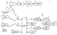
- FIG. 1illustrates a functional block diagram of a communication system in which an embodiment of the present invention is operable.
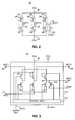
- FIG. 2illustrates a partial circuit schematic, partial functional block diagram, of portions of the switch assembly forming a portion of the mobile station shown in FIG. 1 .
- FIG. 3illustrates a partial circuit schematic, partial functional block diagram, of the switch assembly of an embodiment of the present invention.
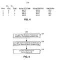
- FIG. 4illustrates a table exemplary of the logical values applied to the switch assembly and corresponding switch positions of the switch elements thereof during operation of an exemplary implementation of the present invention.
- FIG. 5illustrates a method flow diagram listing the method of operation of an embodiment of the present invention.
- a communication systemshowing generally a 10 , provides for radio communications with a mobile station 12 by way of radio links formed with the mobile station.
- the mobile station 12forms a dual-band, tri-mode, cellular mobile station selectably operable in three separate mobile communication systems. While the following description shall describe the mobile station 12 with respect to such an implementation, it should be understood that other embodiments of the present invention can analogously be implemented to be operable in other types of communication systems.
- Three separate network infrastructuresa first network infrastructure 14 , a second network infrastructure 16 , and a third network infrastructure 18 , are installed and are permitting of radio communications with the mobile station 12 when the mobile station is positioned in a geographical area encompassed by the network infrastructure of the respective communication systems.
- the separate network infrastructuresmay be overlaid, or partially overlaid, upon one another.
- the network infrastructuremay be installed at separate geographical areas, and the mobile station communicates with the respective ones of the separate radio communication systems when the mobile station is positioned in the geographical area encompassed by such respective communication systems.
- the network infrastructure 14here is representative of a cellular-band, CDMA (code-division, multi-access) mobile communication system operable at approximately 800 MHz.
- the network infrastructure 16is representative of a cellular-band, AMPS (advanced mobile phone service) mobile communication system also operable at approximately 800 MHz.
- the network infrastructure 18is representative of the network infrastructure of a PCS-band, CDMA mobile communication system operable at approximately 1.9 GHz.
- the network structure 14is here shown to include a base transceiver station 22 , which is operable to transceive radio-frequency, information signals with the mobile station 12 .
- the base transceiver stationis coupled to a base station controller (BSC) 24 .
- BSCbase station controller
- the base station controlleris operable to control operation of the base transceiver station.
- the base station controlleris, in turn, coupled to a mobile switching center (MSC) 25 .
- the switching center 25performs switching operations and is coupled to a network backbone 26 , such as a public-switched telephonic network.
- Remote communication stationssuch as the communication station 28 , are coupled to the network backbone.
- a communication pathis formable between the communication station 28 and the mobile station 12 to permit communications therebetween.
- the network infrastructure 16 and 18includes analogous structure to that shown with respect to the network infrastructure 14 .
- the mobile station 12forms a radio transceiver having radio circuitry for generating and receiving information signals generated during operation of the communication system 10 .
- the radio circuitryincludes both radio transmitter circuitry and radio receiver circuitry, selectably to permit communications by the mobile station 12 with any of the network infrastructure, 14 , 16 and 18 .
- the radio circuitryis of a construction to permit AMPS-based communications at the 800 MHz range, CDMA communications at 800 MHz range and PCS-based, CDMA communications at the 1.9 GHz range.
- the radio circuitryis divided into base band parts and RF (radio frequency) parts.
- the base band partsinclude an AMPS (advanced mobile phone service) part 34 , a digital-cellular part 36 , and a digital PCS part 38 .
- the parts 34 , 36 , and 38are coupled to a data source and data sink 42 .
- the data source and data sinkforms the source at which data to be transmitted by the mobile station is sourced and the data sink to which data received at the mobile station is provided.
- the RF part of the mobile stationis here shown to include an 800 MHz part 44 and a 1.9 GHz part 46 .
- the 800 MHz partis coupled to the base band parts 34 and 36 .
- the 1.9 GHz part 46is coupled to the base band part 38 .
- the various parts of the radio circuitry of the mobile stationare variously operable to effectuate communications pursuant to the communication service through which the communications are effectuated.
- the RF parts 44 and 46 of the radio circuitryare coupled to a switch assembly 50 of an embodiment of the present invention.
- the switch assemblyis also coupled to transducer ports 52 , 54 , and 56 .
- a first antenna transducer 62here a whip antenna, is positioned at the first transducer port 52 .
- a second antenna transducer 64is positioned at the second transducer port 54 .
- the transducer port 56here forming a RF (radio frequency) coupler, permitting connection of the mobile station to an external device 66 .
- the external device 66is representative of testing apparatus or apparatus connecting the mobile station to an external antenna transducer, such as an automotive antenna.
- the switch assemblyis constructed pursuant to an embodiment of the present invention, responsive to input commands generated on the lines 72 and 74 by a mobile station control processor 76 .
- the control commands generated on the line 72 and 74position switch elements of the switch assembly 50 to selectably interconnect any of the transducer ports 52 , 54 , and 56 to any of the RF parts 44 and 46 .
- Any of the desired combinations of connections between the antenna transducer ports and the RF parts of the radio circuitryare effectuable pursuant to the states defined by values of the control commands generated on the line 72 and 74 . In other implementations, other numbers of control lines can be utilized.
- a load element 78is further shown in the figure to be connected to the switch assembly 50 .
- the load elementis selectably coupled to a transducer port to reduce RF coupling between transducers connected to the radio circuitry of the mobile station by the switch assembly.
- FIG. 2illustrates portions of the switch assembly 50 of an embodiment of the present invention.
- the switch assemblyis shown to include several switch element sets, here, a first switch element set 82 , a second switch element set 84 , and a third switch element set 86 .
- the first transducer port 52is positioned between first and second switch elements 88 and 92 of the first switch element set.
- the transducer port 54is positioned between first and second switch elements 94 and 96 of the second switch element set.
- the port 56is positioned between first and second switch elements 98 and 102 of the third switch element set 86 .
- a shunt switch element 104is positioned between the transducer port 54 and the load element 78 .
- First sides of the first switch element 88 , 94 and 98are coupled to the RF part 46 . And, first sides of the switch elements 92 , 96 and 102 are coupled to the RF part 44 .
- the switch elements of the switch element sets 82 , 84 and 86 as well as also the shunt element 104are formed of gallium arscenide (GaAs) semiconductor transistor switches.
- the switch elementsform MEM switches.
- FIG. 3again illustrates the switch assembly 50 of an embodiment of the present invention, again illustrating the switch elements 88 and 92 , 94 and 96 , 98 and 102 , and 104 . Connections of first sides of the elements 88 , 94 , and 98 are then shown to be coupled to the line 47 extending to the RF part 46 . And, first side of the switch elements 92 , 96 and 102 are shown to be coupled by way of the line 45 to the RF part 44 .
- each of the switch elementsis shown to be coupled to a control unit 112 , and the control unit 112 together with the switch elements are embodied at a common substrate 114 , here to form a single integrated circuit device.
- the control unitis coupled to the lines 72 and 74 to receive control inputs generated thereon by the mobile station controller 76 (shown in FIG. 1 ).
- the control unit 112is thereby operable to control the switch position of the switch element of the switch assembly.
- a table, shown generally at 116illustrates exemplary connections effectuated by the switch elements of the switch assembly.
- four statesare defined depending upon the values generated on the lines 72 and 74 , here line 1 and line 2 , respectively.
- line 1is of a logical zero value
- the mobile stationis to be operated in the PCS frequency band without any external connection to the coupler 56 .
- the line 74is of the zero value
- the mobile stationis to be operated in a cellular band together with connection to the external apparatus by way of the port 56 .
- the mobile stationWhen the line 74 is of a logical one value, the mobile station is to be operated in the cellular-band frequency without connection of the external apparatus at the port 56 . Or, the mobile station is to be operated at the PCS band, together with connection of the external apparatus at the port 56 .
- the whip antenna 62When the line 74 is of a logical zero value, the whip antenna 62 is in an extracted position, and when the line 74 is of a logical one value, the whip antenna is in a retracted position.
- the antenna transducersare thereby caused to be connected to respective ones of the parts of the radio circuitry, in manners indicated in the table, responsive to the values generated on the lines 72 and 74 .
- other arrangementsare, of course, possible.
- FIG. 5illustrates a method flow diagram, shown generally at 122 representative of the method of operation of an embodiment of the present invention by which to switchingly connect a selected one of a first antenna transducer port and at least a second antenna transducer port with a selected one of a first circuit and a second circuit.
- the first antenna transducer portis coupled to a first switch element set, which, in turn, is connected to the first circuitry and the second circuitry.
- the second antenna transducer portis coupled to a second switch element set. And, in turn, the second switch element set is connected to the first circuitry and the second circuitry.
- positioning of the first and second switch element setsare controlled, selectably to cause connection of the first antenna transducer port and the second antenna transducer port with the first and second circuitry.
- a manneris provided by which to selectably connect a selected antenna transducer, such as a whip antenna or a patch antenna, to selected portions of the radio circuitry of a multi-mode mobile station, or other communication station.
- a selected antenna transducersuch as a whip antenna or a patch antenna
Landscapes
- Engineering & Computer Science (AREA)
- Computer Networks & Wireless Communication (AREA)
- Signal Processing (AREA)
- Mobile Radio Communication Systems (AREA)
- Variable-Direction Aerials And Aerial Arrays (AREA)
- Transceivers (AREA)
Abstract
Description
Claims (18)
Priority Applications (2)
| Application Number | Priority Date | Filing Date | Title |
|---|---|---|---|
| US09/823,017US6600931B2 (en) | 2001-03-30 | 2001-03-30 | Antenna switch assembly, and associated method, for a radio communication station |
| PCT/IB2002/000910WO2002080391A1 (en) | 2001-03-30 | 2002-03-26 | Antenna switch assembly, and associated method, for a radio communication station |
Applications Claiming Priority (1)
| Application Number | Priority Date | Filing Date | Title |
|---|---|---|---|
| US09/823,017US6600931B2 (en) | 2001-03-30 | 2001-03-30 | Antenna switch assembly, and associated method, for a radio communication station |
Publications (2)
| Publication Number | Publication Date |
|---|---|
| US20020142796A1 US20020142796A1 (en) | 2002-10-03 |
| US6600931B2true US6600931B2 (en) | 2003-07-29 |
Family
ID=25237570
Family Applications (1)
| Application Number | Title | Priority Date | Filing Date |
|---|---|---|---|
| US09/823,017Expired - LifetimeUS6600931B2 (en) | 2001-03-30 | 2001-03-30 | Antenna switch assembly, and associated method, for a radio communication station |
Country Status (2)
| Country | Link |
|---|---|
| US (1) | US6600931B2 (en) |
| WO (1) | WO2002080391A1 (en) |
Cited By (36)
| Publication number | Priority date | Publication date | Assignee | Title |
|---|---|---|---|---|
| US20020147014A1 (en)* | 2001-04-10 | 2002-10-10 | Roozbeh Atarius | Methods, receivers, transmitters, and systems for performing a soft hand-over of a mobile terminal between base stations that communicate using different communication channels |
| US20030017833A1 (en)* | 2001-07-20 | 2003-01-23 | Kyocera Wireless Corporation | System and method for providing auxiliary reception in a wireless communications system |
| US20030083080A1 (en)* | 2001-11-01 | 2003-05-01 | Airbiquity Inc. | Facility and method for wireless transmission of data |
| US20030114188A1 (en)* | 2001-12-18 | 2003-06-19 | Nokia Corporation | Method and apparatus for accommodating two mobile station antennas that operate in the same frequency band |
| US20040198421A1 (en)* | 2003-02-07 | 2004-10-07 | Coan Philip David | Multi-radio terminals with different intermediate frequencies |
| US20050057426A1 (en)* | 2003-08-25 | 2005-03-17 | Grigory Itkin | Antenna switch structure for a mobile terminal of a wireless communication system |
| US20060009177A1 (en)* | 2003-12-18 | 2006-01-12 | Persico Charles J | Low-power wireless diversity receiver with multiple receive paths |
| US20070230401A1 (en)* | 2006-03-31 | 2007-10-04 | Giora Rayzman | Device, system and method of layer 2 handover between hetreogenous networks |
| US20070238482A1 (en)* | 2006-03-30 | 2007-10-11 | Giora Rayzman | Device, system and method of coordination among multiple transceivers |
| US20070242784A1 (en)* | 2005-10-19 | 2007-10-18 | Sampson Wesley A | Diversity receiver for wireless communication |
| US20090284082A1 (en)* | 2008-05-13 | 2009-11-19 | Qualcomm Incorporated | Method and apparatus with negative resistance in wireless power transfers |
| US20100120466A1 (en)* | 2008-11-12 | 2010-05-13 | Nokia Corporation | Multi-mode antenna switching |
| US20100267415A1 (en)* | 2007-11-12 | 2010-10-21 | Panasonic Corporation | Portable wireless device |
| US20110074602A1 (en)* | 2009-09-30 | 2011-03-31 | Itron, Inc. | Gas shut-off valve with feedback |
| US20110074601A1 (en)* | 2009-09-30 | 2011-03-31 | Itron, Inc. | Utility meter with flow rate sensitivity shut off |
| US20110074603A1 (en)* | 2009-09-30 | 2011-03-31 | Itron, Inc. | Safety utility reconnect |
| US20130217344A1 (en)* | 2012-02-17 | 2013-08-22 | Sony Corporation | Integrated circuit and wireless communication apparatus |
| US8774334B2 (en) | 2011-11-09 | 2014-07-08 | Qualcomm Incorporated | Dynamic receiver switching |
| US8854224B2 (en) | 2009-02-10 | 2014-10-07 | Qualcomm Incorporated | Conveying device information relating to wireless charging |
| US8878393B2 (en) | 2008-05-13 | 2014-11-04 | Qualcomm Incorporated | Wireless power transfer for vehicles |
| US8995591B2 (en) | 2013-03-14 | 2015-03-31 | Qualcomm, Incorporated | Reusing a single-chip carrier aggregation receiver to support non-cellular diversity |
| US9118439B2 (en) | 2012-04-06 | 2015-08-25 | Qualcomm Incorporated | Receiver for imbalanced carriers |
| US9154179B2 (en) | 2011-06-29 | 2015-10-06 | Qualcomm Incorporated | Receiver with bypass mode for improved sensitivity |
| US9154356B2 (en) | 2012-05-25 | 2015-10-06 | Qualcomm Incorporated | Low noise amplifiers for carrier aggregation |
| US9172402B2 (en) | 2012-03-02 | 2015-10-27 | Qualcomm Incorporated | Multiple-input and multiple-output carrier aggregation receiver reuse architecture |
| US9178669B2 (en) | 2011-05-17 | 2015-11-03 | Qualcomm Incorporated | Non-adjacent carrier aggregation architecture |
| US9252827B2 (en) | 2011-06-27 | 2016-02-02 | Qualcomm Incorporated | Signal splitting carrier aggregation receiver architecture |
| US9300420B2 (en) | 2012-09-11 | 2016-03-29 | Qualcomm Incorporated | Carrier aggregation receiver architecture |
| US9312924B2 (en) | 2009-02-10 | 2016-04-12 | Qualcomm Incorporated | Systems and methods relating to multi-dimensional wireless charging |
| US9362958B2 (en) | 2012-03-02 | 2016-06-07 | Qualcomm Incorporated | Single chip signal splitting carrier aggregation receiver architecture |
| US9543903B2 (en) | 2012-10-22 | 2017-01-10 | Qualcomm Incorporated | Amplifiers with noise splitting |
| US9583953B2 (en) | 2009-02-10 | 2017-02-28 | Qualcomm Incorporated | Wireless power transfer for portable enclosures |
| US9867194B2 (en) | 2012-06-12 | 2018-01-09 | Qualcomm Incorporated | Dynamic UE scheduling with shared antenna and carrier aggregation |
| US10177722B2 (en) | 2016-01-12 | 2019-01-08 | Qualcomm Incorporated | Carrier aggregation low-noise amplifier with tunable integrated power splitter |
| US11819690B2 (en) | 2007-05-31 | 2023-11-21 | Cochlear Limited | Acoustic output device with antenna |
| US12081243B2 (en) | 2011-08-16 | 2024-09-03 | Qualcomm Incorporated | Low noise amplifiers with combined outputs |
Families Citing this family (16)
| Publication number | Priority date | Publication date | Assignee | Title |
|---|---|---|---|---|
| US7260424B2 (en)* | 2002-05-24 | 2007-08-21 | Schmidt Dominik J | Dynamically configured antenna for multiple frequencies and bandwidths |
| US7242917B2 (en)* | 2002-11-05 | 2007-07-10 | Motorola Inc. | Apparatus and method for antenna attachment |
| EP1593107A4 (en)* | 2003-02-13 | 2010-08-18 | Nokia Corp | METHOD FOR SIGNALING CLIENT RATE CAPACITY FOR MULTIMEDIA BROADCAST |
| DE10345972B4 (en)* | 2003-10-02 | 2006-04-20 | Siemens Ag | Device with adaptive radio transmission and / or radio reception architecture and method for its operation |
| US20050253665A1 (en)* | 2004-05-11 | 2005-11-17 | Vassallo Frank A Ii | Automatic radio frequency signal controller device and associated method |
| US8879983B2 (en)* | 2008-02-06 | 2014-11-04 | Hmicro, Inc. | Wireless communications systems using multiple radios |
| US8897394B1 (en)* | 2008-04-08 | 2014-11-25 | Marvell International Ltd. | Methods and apparatus for adaptively selecting a communications mode in high frequency systems |
| CN101904191B (en)* | 2008-09-26 | 2013-06-12 | 华为技术有限公司 | Method and apparatus of communication |
| KR101809273B1 (en)* | 2011-08-12 | 2018-01-18 | 아주대학교산학협력단 | Terminal and control method thereof in a communication system |
| CN104619046B (en)* | 2013-11-04 | 2018-06-05 | 展讯通信(上海)有限公司 | Communication terminal |
| CN104618884B (en)* | 2013-11-04 | 2018-06-05 | 展讯通信(上海)有限公司 | The newer method of 2G/3G subdistrict positions is realized under LTE PS connection status |
| CN104618527B (en)* | 2013-11-04 | 2018-06-05 | 展讯通信(上海)有限公司 | Antenna-switching device and communication terminal |
| CN104618939B (en)* | 2013-11-04 | 2018-10-16 | 展讯通信(上海)有限公司 | The method that 2G/3G circuit domain calling services are realized under LTE PS connection status |
| CN104617979B (en)* | 2013-11-04 | 2017-03-29 | 展讯通信(上海)有限公司 | Mobile telecommunication method |
| CN104618975B (en)* | 2013-11-04 | 2018-06-05 | 展讯通信(上海)有限公司 | The method that 2G/3G circuit domain called services are realized under LTE PS connection status |
| WO2025171643A1 (en)* | 2024-02-18 | 2025-08-21 | Qualcomm Incorporated | Antenna with selectable radio frequency circuit and ground connections |
Citations (8)
| Publication number | Priority date | Publication date | Assignee | Title |
|---|---|---|---|---|
| US5768691A (en)* | 1996-08-07 | 1998-06-16 | Nokia Mobile Phones Limited | Antenna switching circuits for radio telephones |
| US5878332A (en)* | 1997-02-07 | 1999-03-02 | Eic Enterprises Corporation | Multiple frequency RF transceiver |
| US6049705A (en)* | 1998-02-03 | 2000-04-11 | Ericsson Inc. | Diversity for mobile terminals |
| US6072993A (en)* | 1997-08-12 | 2000-06-06 | Sony Corporation | Portable radio transceiver with diplexer-switch circuit for dual frequency band operation |
| US6256495B1 (en)* | 1997-09-17 | 2001-07-03 | Agere Systems Guardian Corp. | Multiport, multiband semiconductor switching and transmission circuit |
| US6351628B1 (en)* | 2000-03-06 | 2002-02-26 | Motorola, Inc. | Antenna switching circuit |
| US6393279B1 (en)* | 1998-08-24 | 2002-05-21 | Samsung Electronics, Co., Ltd. | Method for selecting cells in multiband system |
| US6535748B1 (en)* | 1998-05-27 | 2003-03-18 | Nokia Mobile Phones Ltd. | Wireless communication transceiver having a dual mode of operation |
- 2001
- 2001-03-30USUS09/823,017patent/US6600931B2/ennot_activeExpired - Lifetime
- 2002
- 2002-03-26WOPCT/IB2002/000910patent/WO2002080391A1/ennot_activeApplication Discontinuation
Patent Citations (8)
| Publication number | Priority date | Publication date | Assignee | Title |
|---|---|---|---|---|
| US5768691A (en)* | 1996-08-07 | 1998-06-16 | Nokia Mobile Phones Limited | Antenna switching circuits for radio telephones |
| US5878332A (en)* | 1997-02-07 | 1999-03-02 | Eic Enterprises Corporation | Multiple frequency RF transceiver |
| US6072993A (en)* | 1997-08-12 | 2000-06-06 | Sony Corporation | Portable radio transceiver with diplexer-switch circuit for dual frequency band operation |
| US6256495B1 (en)* | 1997-09-17 | 2001-07-03 | Agere Systems Guardian Corp. | Multiport, multiband semiconductor switching and transmission circuit |
| US6049705A (en)* | 1998-02-03 | 2000-04-11 | Ericsson Inc. | Diversity for mobile terminals |
| US6535748B1 (en)* | 1998-05-27 | 2003-03-18 | Nokia Mobile Phones Ltd. | Wireless communication transceiver having a dual mode of operation |
| US6393279B1 (en)* | 1998-08-24 | 2002-05-21 | Samsung Electronics, Co., Ltd. | Method for selecting cells in multiband system |
| US6351628B1 (en)* | 2000-03-06 | 2002-02-26 | Motorola, Inc. | Antenna switching circuit |
Cited By (76)
| Publication number | Priority date | Publication date | Assignee | Title |
|---|---|---|---|---|
| US20020147014A1 (en)* | 2001-04-10 | 2002-10-10 | Roozbeh Atarius | Methods, receivers, transmitters, and systems for performing a soft hand-over of a mobile terminal between base stations that communicate using different communication channels |
| US6920324B2 (en)* | 2001-04-10 | 2005-07-19 | Ericsson Inc. | Methods, receivers, transmitters, and systems for performing a soft hand-over of a mobile terminal between base stations that communicate using different communication channels |
| US7181171B2 (en)* | 2001-07-20 | 2007-02-20 | Kyocera Wireless Corp. | System and method for providing auxiliary reception in a wireless communications system |
| US20030017833A1 (en)* | 2001-07-20 | 2003-01-23 | Kyocera Wireless Corporation | System and method for providing auxiliary reception in a wireless communications system |
| US20030083080A1 (en)* | 2001-11-01 | 2003-05-01 | Airbiquity Inc. | Facility and method for wireless transmission of data |
| US7509134B2 (en) | 2001-11-01 | 2009-03-24 | Airbiquity Inc. | Remote method for wireless transmission of location data |
| US7215965B2 (en)* | 2001-11-01 | 2007-05-08 | Airbiquity Inc. | Facility and method for wireless transmission of location data in a voice channel of a digital wireless telecommunications network |
| US20070072625A1 (en)* | 2001-11-01 | 2007-03-29 | Airbiquity Inc. | Remote method for wireless transmission of location data |
| US20030114188A1 (en)* | 2001-12-18 | 2003-06-19 | Nokia Corporation | Method and apparatus for accommodating two mobile station antennas that operate in the same frequency band |
| US7194284B2 (en)* | 2001-12-18 | 2007-03-20 | Nokia Corporation | Method and apparatus for accommodating two mobile station antennas that operate in the same frequency band |
| US20040198421A1 (en)* | 2003-02-07 | 2004-10-07 | Coan Philip David | Multi-radio terminals with different intermediate frequencies |
| US20050057426A1 (en)* | 2003-08-25 | 2005-03-17 | Grigory Itkin | Antenna switch structure for a mobile terminal of a wireless communication system |
| US20060009177A1 (en)* | 2003-12-18 | 2006-01-12 | Persico Charles J | Low-power wireless diversity receiver with multiple receive paths |
| US9026070B2 (en) | 2003-12-18 | 2015-05-05 | Qualcomm Incorporated | Low-power wireless diversity receiver with multiple receive paths |
| US9450665B2 (en)* | 2005-10-19 | 2016-09-20 | Qualcomm Incorporated | Diversity receiver for wireless communication |
| US20070242784A1 (en)* | 2005-10-19 | 2007-10-18 | Sampson Wesley A | Diversity receiver for wireless communication |
| US20070238482A1 (en)* | 2006-03-30 | 2007-10-11 | Giora Rayzman | Device, system and method of coordination among multiple transceivers |
| US7778226B2 (en)* | 2006-03-30 | 2010-08-17 | Intel Corporation | Device, system and method of coordination among multiple transceivers |
| US7697481B2 (en) | 2006-03-31 | 2010-04-13 | Intel Corporation | Device, system and method of layer 2 handover between hereogenous networks |
| US20070230401A1 (en)* | 2006-03-31 | 2007-10-04 | Giora Rayzman | Device, system and method of layer 2 handover between hetreogenous networks |
| US12011593B2 (en) | 2007-05-31 | 2024-06-18 | Cochlear Limited | Acoustic output device with antenna |
| US11819690B2 (en) | 2007-05-31 | 2023-11-21 | Cochlear Limited | Acoustic output device with antenna |
| US8301192B2 (en)* | 2007-11-12 | 2012-10-30 | Panasonic Corporation | Portable wireless device |
| US20100267415A1 (en)* | 2007-11-12 | 2010-10-21 | Panasonic Corporation | Portable wireless device |
| US9184632B2 (en) | 2008-05-13 | 2015-11-10 | Qualcomm Incorporated | Wireless power transfer for furnishings and building elements |
| CN102027691B (en)* | 2008-05-13 | 2014-11-05 | 高通股份有限公司 | wireless power receiver |
| US20090284218A1 (en)* | 2008-05-13 | 2009-11-19 | Qualcomm Incorporated | Method and apparatus for an enlarged wireless charging area |
| US20090284220A1 (en)* | 2008-05-13 | 2009-11-19 | Qualcomm Incorporated | Method and apparatus for adaptive tuning of wireless power transfer |
| US20090286475A1 (en)* | 2008-05-13 | 2009-11-19 | Qualcomm Incorporated | Signaling charging in wireless power environment |
| US9190875B2 (en) | 2008-05-13 | 2015-11-17 | Qualcomm Incorporated | Method and apparatus with negative resistance in wireless power transfers |
| US9236771B2 (en) | 2008-05-13 | 2016-01-12 | Qualcomm Incorporated | Method and apparatus for adaptive tuning of wireless power transfer |
| CN102027691A (en)* | 2008-05-13 | 2011-04-20 | 高通股份有限公司 | Reverse link signaling via receive antenna impedance modulation |
| US20090284227A1 (en)* | 2008-05-13 | 2009-11-19 | Qualcomm Incorporated | Receive antenna for wireless power transfer |
| US8487478B2 (en) | 2008-05-13 | 2013-07-16 | Qualcomm Incorporated | Wireless power transfer for appliances and equipments |
| US20090284245A1 (en)* | 2008-05-13 | 2009-11-19 | Qualcomm Incorporated | Wireless power transfer for appliances and equipments |
| US20090284082A1 (en)* | 2008-05-13 | 2009-11-19 | Qualcomm Incorporated | Method and apparatus with negative resistance in wireless power transfers |
| US8611815B2 (en) | 2008-05-13 | 2013-12-17 | Qualcomm Incorporated | Repeaters for enhancement of wireless power transfer |
| US8629650B2 (en) | 2008-05-13 | 2014-01-14 | Qualcomm Incorporated | Wireless power transfer using multiple transmit antennas |
| US20090286476A1 (en)* | 2008-05-13 | 2009-11-19 | Qualcomm Incorporated | Reverse link signaling via receive antenna impedance modulation |
| US9130407B2 (en) | 2008-05-13 | 2015-09-08 | Qualcomm Incorporated | Signaling charging in wireless power environment |
| US8878393B2 (en) | 2008-05-13 | 2014-11-04 | Qualcomm Incorporated | Wireless power transfer for vehicles |
| US9178387B2 (en) | 2008-05-13 | 2015-11-03 | Qualcomm Incorporated | Receive antenna for wireless power transfer |
| US20090286470A1 (en)* | 2008-05-13 | 2009-11-19 | Qualcomm Incorporated | Repeaters for enhancement of wireless power transfer |
| US8892035B2 (en) | 2008-05-13 | 2014-11-18 | Qualcomm Incorporated | Repeaters for enhancement of wireless power transfer |
| US9991747B2 (en) | 2008-05-13 | 2018-06-05 | Qualcomm Incorporated | Signaling charging in wireless power environment |
| US8965461B2 (en)* | 2008-05-13 | 2015-02-24 | Qualcomm Incorporated | Reverse link signaling via receive antenna impedance modulation |
| US9954399B2 (en) | 2008-05-13 | 2018-04-24 | Qualcomm Incorporated | Reverse link signaling via receive antenna impedance modulation |
| US20100120466A1 (en)* | 2008-11-12 | 2010-05-13 | Nokia Corporation | Multi-mode antenna switching |
| US9583953B2 (en) | 2009-02-10 | 2017-02-28 | Qualcomm Incorporated | Wireless power transfer for portable enclosures |
| US8854224B2 (en) | 2009-02-10 | 2014-10-07 | Qualcomm Incorporated | Conveying device information relating to wireless charging |
| US9312924B2 (en) | 2009-02-10 | 2016-04-12 | Qualcomm Incorporated | Systems and methods relating to multi-dimensional wireless charging |
| US8890711B2 (en)* | 2009-09-30 | 2014-11-18 | Itron, Inc. | Safety utility reconnect |
| US8493232B2 (en) | 2009-09-30 | 2013-07-23 | Itron, Inc. | Gas shut-off valve with feedback |
| US20110074603A1 (en)* | 2009-09-30 | 2011-03-31 | Itron, Inc. | Safety utility reconnect |
| US20110074601A1 (en)* | 2009-09-30 | 2011-03-31 | Itron, Inc. | Utility meter with flow rate sensitivity shut off |
| US20110074602A1 (en)* | 2009-09-30 | 2011-03-31 | Itron, Inc. | Gas shut-off valve with feedback |
| US9178669B2 (en) | 2011-05-17 | 2015-11-03 | Qualcomm Incorporated | Non-adjacent carrier aggregation architecture |
| US9252827B2 (en) | 2011-06-27 | 2016-02-02 | Qualcomm Incorporated | Signal splitting carrier aggregation receiver architecture |
| US9154179B2 (en) | 2011-06-29 | 2015-10-06 | Qualcomm Incorporated | Receiver with bypass mode for improved sensitivity |
| US12081243B2 (en) | 2011-08-16 | 2024-09-03 | Qualcomm Incorporated | Low noise amplifiers with combined outputs |
| US8774334B2 (en) | 2011-11-09 | 2014-07-08 | Qualcomm Incorporated | Dynamic receiver switching |
| US8909168B2 (en)* | 2012-02-17 | 2014-12-09 | Sony Corporation | Integrated circuit and wireless communication apparatus |
| US20130217344A1 (en)* | 2012-02-17 | 2013-08-22 | Sony Corporation | Integrated circuit and wireless communication apparatus |
| US9172402B2 (en) | 2012-03-02 | 2015-10-27 | Qualcomm Incorporated | Multiple-input and multiple-output carrier aggregation receiver reuse architecture |
| US9362958B2 (en) | 2012-03-02 | 2016-06-07 | Qualcomm Incorporated | Single chip signal splitting carrier aggregation receiver architecture |
| US9118439B2 (en) | 2012-04-06 | 2015-08-25 | Qualcomm Incorporated | Receiver for imbalanced carriers |
| US9154356B2 (en) | 2012-05-25 | 2015-10-06 | Qualcomm Incorporated | Low noise amplifiers for carrier aggregation |
| US9154357B2 (en) | 2012-05-25 | 2015-10-06 | Qualcomm Incorporated | Multiple-input multiple-output (MIMO) low noise amplifiers for carrier aggregation |
| US9160598B2 (en) | 2012-05-25 | 2015-10-13 | Qualcomm Incorporated | Low noise amplifiers with cascode divert switch for carrier aggregation |
| US9166852B2 (en) | 2012-05-25 | 2015-10-20 | Qualcomm Incorporated | Low noise amplifiers with transformer-based signal splitting for carrier aggregation |
| US9867194B2 (en) | 2012-06-12 | 2018-01-09 | Qualcomm Incorporated | Dynamic UE scheduling with shared antenna and carrier aggregation |
| US9300420B2 (en) | 2012-09-11 | 2016-03-29 | Qualcomm Incorporated | Carrier aggregation receiver architecture |
| US9543903B2 (en) | 2012-10-22 | 2017-01-10 | Qualcomm Incorporated | Amplifiers with noise splitting |
| US9837968B2 (en) | 2012-10-22 | 2017-12-05 | Qualcomm Incorporated | Amplifier circuits |
| US8995591B2 (en) | 2013-03-14 | 2015-03-31 | Qualcomm, Incorporated | Reusing a single-chip carrier aggregation receiver to support non-cellular diversity |
| US10177722B2 (en) | 2016-01-12 | 2019-01-08 | Qualcomm Incorporated | Carrier aggregation low-noise amplifier with tunable integrated power splitter |
Also Published As
| Publication number | Publication date |
|---|---|
| WO2002080391A1 (en) | 2002-10-10 |
| US20020142796A1 (en) | 2002-10-03 |
Similar Documents
| Publication | Publication Date | Title |
|---|---|---|
| US6600931B2 (en) | Antenna switch assembly, and associated method, for a radio communication station | |
| US7142884B2 (en) | Combined front-end circuit for wireless transmission systems | |
| US6816711B2 (en) | GPS equipped mobile phone with single shared antenna | |
| KR101060874B1 (en) | Sending and receiving circuit and sending and receiving method | |
| US6662021B2 (en) | Mobile communication system having multi-band antenna | |
| US6480155B1 (en) | Antenna assembly, and associated method, having an active antenna element and counter antenna element | |
| US20040204037A1 (en) | RF front-end for dual-band wireless transceiver module | |
| JP4484871B2 (en) | Frequency selective device and method of receiving / transmitting communication signal in wireless multiband device thereof | |
| EP1483836B1 (en) | System and method for a gps enabled antenna | |
| EP1402651B1 (en) | System for a gps enabled antenna | |
| US20060160507A1 (en) | GPS receiver in moblie communications devices | |
| US6510310B1 (en) | Dual mode phone architecture utilizing a single transmit-receive switch | |
| KR100514568B1 (en) | Signal combining device and method for radio communication | |
| EP0964477B1 (en) | Antenna sharing device for dual frequency band | |
| US20140153493A1 (en) | Sector-based base station | |
| CN110971245B (en) | Radio frequency circuit, control method thereof and mobile terminal | |
| KR20040078699A (en) | Mobile multimode terminal with joint power amplifier | |
| US20070123174A1 (en) | Device and method for single connector access to multiple transceivers | |
| US6381446B1 (en) | Controllable filter | |
| CN112189378A (en) | Vehicle-mounted antenna system and communication method applied to same | |
| KR20100037666A (en) | Multi standby portable terminal | |
| KR101686432B1 (en) | Method and apparatus for controlling multi band antenna in mobile communication temianl | |
| US20040095919A1 (en) | Composite high-frequency part and information terminal apparatus using the same | |
| US20090219837A1 (en) | Signal transceive for wireless communication device | |
| KR20060112722A (en) | Antenna Matching Circuit for Multi-Band Terminals |
Legal Events
| Date | Code | Title | Description |
|---|---|---|---|
| AS | Assignment | Owner name:NOKIA MOBILE PHONES LIMITED, FINLAND Free format text:ASSIGNMENT OF ASSIGNORS INTEREST;ASSIGNORS:SUTTON, GREGORY;LI, KEVIN;MIX, ROBERT;AND OTHERS;REEL/FRAME:011927/0624;SIGNING DATES FROM 20010510 TO 20010524 | |
| STCF | Information on status: patent grant | Free format text:PATENTED CASE | |
| FPAY | Fee payment | Year of fee payment:4 | |
| FPAY | Fee payment | Year of fee payment:8 | |
| FPAY | Fee payment | Year of fee payment:12 | |
| AS | Assignment | Owner name:NOKIA TECHNOLOGIES OY, FINLAND Free format text:ASSIGNMENT OF ASSIGNORS INTEREST;ASSIGNOR:NOKIA CORPORATION;REEL/FRAME:036067/0222 Effective date:20150116 | |
| AS | Assignment | Owner name:PROVENANCE ASSET GROUP LLC, CONNECTICUT Free format text:ASSIGNMENT OF ASSIGNORS INTEREST;ASSIGNORS:NOKIA TECHNOLOGIES OY;NOKIA SOLUTIONS AND NETWORKS BV;ALCATEL LUCENT SAS;REEL/FRAME:043877/0001 Effective date:20170912 Owner name:NOKIA USA INC., CALIFORNIA Free format text:SECURITY INTEREST;ASSIGNORS:PROVENANCE ASSET GROUP HOLDINGS, LLC;PROVENANCE ASSET GROUP LLC;REEL/FRAME:043879/0001 Effective date:20170913 Owner name:CORTLAND CAPITAL MARKET SERVICES, LLC, ILLINOIS Free format text:SECURITY INTEREST;ASSIGNORS:PROVENANCE ASSET GROUP HOLDINGS, LLC;PROVENANCE ASSET GROUP, LLC;REEL/FRAME:043967/0001 Effective date:20170913 | |
| AS | Assignment | Owner name:NOKIA US HOLDINGS INC., NEW JERSEY Free format text:ASSIGNMENT AND ASSUMPTION AGREEMENT;ASSIGNOR:NOKIA USA INC.;REEL/FRAME:048370/0682 Effective date:20181220 | |
| AS | Assignment | Owner name:PROVENANCE ASSET GROUP LLC, CONNECTICUT Free format text:RELEASE BY SECURED PARTY;ASSIGNOR:CORTLAND CAPITAL MARKETS SERVICES LLC;REEL/FRAME:058983/0104 Effective date:20211101 Owner name:PROVENANCE ASSET GROUP HOLDINGS LLC, CONNECTICUT Free format text:RELEASE BY SECURED PARTY;ASSIGNOR:CORTLAND CAPITAL MARKETS SERVICES LLC;REEL/FRAME:058983/0104 Effective date:20211101 Owner name:PROVENANCE ASSET GROUP LLC, CONNECTICUT Free format text:RELEASE BY SECURED PARTY;ASSIGNOR:NOKIA US HOLDINGS INC.;REEL/FRAME:058363/0723 Effective date:20211129 Owner name:PROVENANCE ASSET GROUP HOLDINGS LLC, CONNECTICUT Free format text:RELEASE BY SECURED PARTY;ASSIGNOR:NOKIA US HOLDINGS INC.;REEL/FRAME:058363/0723 Effective date:20211129 | |
| AS | Assignment | Owner name:RPX CORPORATION, CALIFORNIA Free format text:ASSIGNMENT OF ASSIGNORS INTEREST;ASSIGNOR:PROVENANCE ASSET GROUP LLC;REEL/FRAME:059352/0001 Effective date:20211129 |