US6600307B2 - Method and apparatus for measuring true transmitted power using a broadband dual directional coupler - Google Patents
Method and apparatus for measuring true transmitted power using a broadband dual directional couplerDownload PDFInfo
- Publication number
- US6600307B2 US6600307B2US09/742,768US74276800AUS6600307B2US 6600307 B2US6600307 B2US 6600307B2US 74276800 AUS74276800 AUS 74276800AUS 6600307 B2US6600307 B2US 6600307B2
- Authority
- US
- United States
- Prior art keywords
- coupling section
- radiating element
- substrate
- directional coupler
- power
- Prior art date
- Legal status (The legal status is an assumption and is not a legal conclusion. Google has not performed a legal analysis and makes no representation as to the accuracy of the status listed.)
- Expired - Lifetime, expires
Links
- 230000009977dual effectEffects0.000titledescription4
- 238000000034methodMethods0.000titledescription3
- 230000008878couplingEffects0.000claimsdescription35
- 238000010168coupling processMethods0.000claimsdescription35
- 238000005859coupling reactionMethods0.000claimsdescription35
- 239000000758substrateSubstances0.000claimsdescription19
- 230000001413cellular effectEffects0.000claimsdescription7
- 239000000919ceramicSubstances0.000claimsdescription7
- 238000010586diagramMethods0.000description4
- 238000005259measurementMethods0.000description2
- 230000007812deficiencyEffects0.000description1
- 230000014509gene expressionEffects0.000description1
- 238000002955isolationMethods0.000description1
- 238000000926separation methodMethods0.000description1
Images

Classifications
- G—PHYSICS
- G01—MEASURING; TESTING
- G01R—MEASURING ELECTRIC VARIABLES; MEASURING MAGNETIC VARIABLES
- G01R21/00—Arrangements for measuring electric power or power factor
- G01R21/02—Arrangements for measuring electric power or power factor by thermal methods, e.g. calorimetric
- G01R21/04—Arrangements for measuring electric power or power factor by thermal methods, e.g. calorimetric in circuits having distributed constants
- G—PHYSICS
- G01—MEASURING; TESTING
- G01R—MEASURING ELECTRIC VARIABLES; MEASURING MAGNETIC VARIABLES
- G01R21/00—Arrangements for measuring electric power or power factor
- G01R21/10—Arrangements for measuring electric power or power factor by using square-law characteristics of circuit elements, e.g. diodes, to measure power absorbed by loads of known impedance
- G01R21/12—Arrangements for measuring electric power or power factor by using square-law characteristics of circuit elements, e.g. diodes, to measure power absorbed by loads of known impedance in circuits having distributed constants
Definitions
- This inventionrelates to radio frequency directional couplers and, more particularly, to a dual directional coupler that generates a true transmitted power measurement.
- the performance of cellular telephony and similar duplex wireless communications systemsdepend strongly on dynamic control of the power transmitted by each base station and each portable terminal.
- the Federal Communications Commission (FCC)to keep power levels within a safe level, mandates precise control of the power transmitted from the portable terminal.
- Prior art methods of measuring transmitted power in a portable terminaluse a directional coupler to only sample the incident power at the radiating element.
- a radiating elementmay not be perfectly matched to the characteristic impedance of the feedline and a radiating element's impedance characteristics change as the portable terminal changes its location and proximity to other objects.
- the antennawere to be disconnected, the power to the antenna would be measured as being correct even though no power was transmitted. Therefore, it cannot be assumed that the transmitted power be derived with any degree of accuracy from the measured incident power alone.
- the present inventionovercomes the deficiencies found in the prior art and satisfies the need for a device that can provide an accurate measurement of true transmitted power at the radiating element within a small footprint and a low cost mandated by portable terminals.
- the present inventionis a dual-directional coupler comprising two detector circuits that generate voltages proportional to the incident power and reflected power.
- the voltages from the detector circuitsare coupled to a differential amplifier.
- the differential amplifiergenerates a voltage proportional to the difference between the incident power and reflected power that represents the true transmitted power at the radiating element.
- the dual-directional coupleris fabricated on a ceramic substrate to facilitate a compact, surface mount implementation. Such a compact coupler can be easily installed in a cellular telephone.
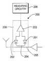
- FIG. 1depicts a schematic diagram of a prior art directional coupler
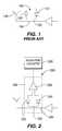
- FIG. 2shows a schematic diagram of a dual-directional coupler in accordance with the invention
- FIG. 3shows a performance graph of the tuned coupler section
- FIG. 4shows a perspective view of a dual-directional coupler contained in a surface mount device in accordance with the invention.
- FIG. 1shows a schematic diagram of a prior art directional coupler 100 comprising a detector 101 , a terminal impedance 102 , a tuned length coupling section 103 and a radio frequency (RF) feed-line 104 placed in close proximity to the coupling section 103 .
- RFradio frequency
- the prior art directional coupler circuitonly samples incident power present at the radiating element and does not detect any probable reflected power loss due to impedance mismatch at a radiating element 106 , the reflected power being dissipated in the terminating resistance 102 .
- FIG. 2shows a schematic diagram of dual directional coupler 200 in accordance with the invention.
- Dual directional coupler 200comprises a first detector 201 (e.g., an RF diode) having an anode and cathode terminal, a second detector 202 (e.g., an RF diode) having an anode and cathode terminal, a differential amplifier 203 having a first input terminal coupled to the anode of the first detector 201 , a second input terminal coupled to the anode of the second detector 203 and an output terminal, a tuned length coupling section 204 having an input terminal coupled to the cathode of the first detector 201 and an output terminal coupled to the cathode of the second detector 202 , and an RF feed-line section 205 having an input and output terminal placed in close proximity to the coupling section 204 .
- a first detector 201e.g., an RF diode
- second detector 202e.g., an RF diode
- the coupling section 204 and feedline section 205are striplines that are mounted on a substrate 208 .
- the output terminal of the differential amplifier 203may be connected to analog or digital voltage measuring circuits 206 known in the art. These circuits may comprise an analog to digital converter (ADC) for producing a digital word representing the true transmittal RF power.
- ADCanalog to digital converter
- the ADCmay or may not be affixed to the coupler substrate 208 .
- the dual-directional coupler 200with directivity D, provides separation between the incident power Pi present at the input terminal of the coupling section 204 and the reflected power Pr present at the output of the coupling section 204 .
- the transmitted powercan be represented as:
- the transmitted powercan be represented as:
- First and second detector unitsoperate in the square law region such that the output voltages are linearly proportional to P i and P r .
- FIG. 3shows a graph plotting frequency (axis 304 ) versus power (axis 306 ) of tuned coupling section 204 .
- Coupling performance shown in the upper trace 301 of the graphindicates the amount of RF power sampled from the RF feedline 205 .
- Return loss performance shown in the middle trace 302 of the graphis a measure of how well the coupler is matched to a 50 ohm system.
- Isolation performance shown in the bottom trace 303 of the graphindicates the magnitude of the undesired signal present at each coupled port.
- a tuned coupling section 204It is desirable to construct a tuned coupling section 204 to have a flat impedance response across the 850 MHz Cellular and 1.9 GHz PCS mobile telephony bands. It is also desirable for the tuned coupling section 204 to have approximately ⁇ 20 db of coupling throughout the desired frequency range. To achieve the foregoing with a desired coupling section length of 0.22 cm and a desired electrical length of 13.1°, it is determined through mathematical expressions well known in the art that even and odd mode impedances of a 7.7 db coupler are required.
- the tuned coupling section 204has a width of 0.30 mm and a spacing of 0.30 mm from the RF feed-line 205 and a ceramic substrate.
- the ceramic substratecan be manufactured using a low temperature ceramic circuit (LTCC) technique to achieve a tailored dielectric constant.
- LTCClow temperature ceramic circuit
- This implementationproduces a dual-directional coupler in a ceramic package that is approximately 100 mils ⁇ 100 mils. Such a small package enables the coupler to be used in cellular telephones and other small electronic applications.
- RF poweris applied to the input terminal of the RF feed-line 205 .
- a small amount of RF poweris induced into the tuned coupling section 204 .
- the first detector 201detects incident power present and couples a proportional voltage to the first input of the differential amplifier 203 .
- the second detector 202detects reflected power present and couples a proportional voltage to the second input of the differential amplifier 203 .
- the differential amplifier 203algebraically combines voltages from the first and second inputs and produces a voltage proportional to the actual power present at the radiating element.
- the analog output from the detectors 201 and 202may be used without the differential amplifier 203 .
- a further applicationmay couple the sampled RF to circuitry that is not on the coupler's substrate.
- FIG. 4depicts a perspective view of one embodiment of the invention. Due to the substantial limitations on the use of printed circuit boards (PCB) surface area in such mobile devices as cellular telephones, the invention is implemented using a printed/hybrid implementation. This implementation is selected to enable the device to operate in both the cellular and PCS bands simultaneously while maintaining a low profile of less than 2.54 ⁇ 2.54 ⁇ 3 mm in a surface mount package (module).
- the coupler 200is surface mounted to PCB 400 .
- Circuit traces 402 , 404 , and 406carry input RF, output RF an detected signals, respectively.
- the detectors 201 and 202 and the differential amplifier 203are mounted to the top of the coupler 200 .
Landscapes
- Engineering & Computer Science (AREA)
- Power Engineering (AREA)
- Physics & Mathematics (AREA)
- General Physics & Mathematics (AREA)
- Transmitters (AREA)
- Amplifiers (AREA)
- Transceivers (AREA)
Abstract
Description
Claims (18)
Priority Applications (1)
| Application Number | Priority Date | Filing Date | Title |
|---|---|---|---|
| US09/742,768US6600307B2 (en) | 2000-03-02 | 2000-12-21 | Method and apparatus for measuring true transmitted power using a broadband dual directional coupler |
Applications Claiming Priority (2)
| Application Number | Priority Date | Filing Date | Title |
|---|---|---|---|
| US18654600P | 2000-03-02 | 2000-03-02 | |
| US09/742,768US6600307B2 (en) | 2000-03-02 | 2000-12-21 | Method and apparatus for measuring true transmitted power using a broadband dual directional coupler |
Publications (2)
| Publication Number | Publication Date |
|---|---|
| US20010048311A1 US20010048311A1 (en) | 2001-12-06 |
| US6600307B2true US6600307B2 (en) | 2003-07-29 |
Family
ID=22685365
Family Applications (1)
| Application Number | Title | Priority Date | Filing Date |
|---|---|---|---|
| US09/742,768Expired - LifetimeUS6600307B2 (en) | 2000-03-02 | 2000-12-21 | Method and apparatus for measuring true transmitted power using a broadband dual directional coupler |
Country Status (5)
| Country | Link |
|---|---|
| US (1) | US6600307B2 (en) |
| EP (1) | EP1259830A4 (en) |
| JP (1) | JP2003525455A (en) |
| KR (1) | KR20030010586A (en) |
| WO (1) | WO2001065267A1 (en) |
Cited By (19)
| Publication number | Priority date | Publication date | Assignee | Title |
|---|---|---|---|---|
| US20040243326A1 (en)* | 2003-05-30 | 2004-12-02 | Daoud Bassel H. | Method and apparatus for measuring the transmission loss of a cable |
| US6969985B2 (en)* | 2001-12-14 | 2005-11-29 | Analog Devices, Inc. | Active coupler |
| US20070026838A1 (en)* | 2005-07-27 | 2007-02-01 | Joseph Staudinger | Power amplifier with VSWR detection and correction feature |
| US20070222539A1 (en)* | 2006-03-24 | 2007-09-27 | R & D Microwaves Llc | Dual directional coupler |
| US20100197365A1 (en)* | 2007-06-26 | 2010-08-05 | Skyworks Solutions, Inc. | Error vector magnitude control within a linear transmitter |
| US7942931B2 (en) | 2002-02-21 | 2011-05-17 | Spiration, Inc. | Device and method for intra-bronchial provision of a therapeutic agent |
| US8021385B2 (en) | 2002-03-20 | 2011-09-20 | Spiration, Inc. | Removable anchored lung volume reduction devices and methods |
| US8043301B2 (en) | 2007-10-12 | 2011-10-25 | Spiration, Inc. | Valve loader method, system, and apparatus |
| US8079368B2 (en) | 2003-04-08 | 2011-12-20 | Spiration, Inc. | Bronchoscopic lung volume reduction method |
| US8136230B2 (en) | 2007-10-12 | 2012-03-20 | Spiration, Inc. | Valve loader method, system, and apparatus |
| US8414655B2 (en) | 2001-09-11 | 2013-04-09 | Spiration, Inc. | Removable lung reduction devices, systems, and methods |
| US8454708B2 (en) | 2006-03-31 | 2013-06-04 | Spiration, Inc. | Articulable anchor |
| US8795241B2 (en) | 2011-05-13 | 2014-08-05 | Spiration, Inc. | Deployment catheter |
| KR20150002524A (en)* | 2013-06-28 | 2015-01-07 | 인피니언 테크놀로지스 아게 | System and method for a transformer and a phase-shift network |
| US8974527B2 (en) | 2003-08-08 | 2015-03-10 | Spiration, Inc. | Bronchoscopic repair of air leaks in a lung |
| US8986336B2 (en) | 2001-10-25 | 2015-03-24 | Spiration, Inc. | Apparatus and method for deployment of a bronchial obstruction device |
| US20150091668A1 (en)* | 2013-10-01 | 2015-04-02 | Infineon Technologies Ag | System and Method for a Radio Frequency Coupler |
| US9322858B2 (en) | 2014-02-04 | 2016-04-26 | Infineon Technologies Austria Ag | System and method for a phase detector |
| US9543631B1 (en) | 2015-09-02 | 2017-01-10 | R & D Microwaves, LLC | Tapered airline directional coupler |
Families Citing this family (7)
| Publication number | Priority date | Publication date | Assignee | Title |
|---|---|---|---|---|
| DE10205359A1 (en)* | 2002-02-08 | 2003-08-21 | Rohde & Schwarz | Power detector with DC decoupling |
| US6954104B2 (en) | 2003-03-12 | 2005-10-11 | Renesas Technology America, Inc. | Method and system for monitoring a deliverable radio frequency power of an amplifier operable on a monolithic microwave integrated circuit |
| US6995580B2 (en)* | 2003-03-19 | 2006-02-07 | Sige Semiconductor Inc. | Power detectors for measuring power coupling |
| US20080224690A1 (en)* | 2008-05-31 | 2008-09-18 | Agilent Technologies, Inc. | Embedded Directional Power Sensing |
| US8620225B2 (en) | 2008-12-15 | 2013-12-31 | Nec Corporation | Power detection circuit, transmitter, and power detection method |
| GB0914926D0 (en)* | 2009-08-26 | 2009-09-30 | Secr Defence | Hybrid RF reflection measurement system (HRS) |
| US9608305B2 (en)* | 2014-01-14 | 2017-03-28 | Infineon Technologies Ag | System and method for a directional coupler with a combining circuit |
Citations (15)
| Publication number | Priority date | Publication date | Assignee | Title |
|---|---|---|---|---|
| US3789301A (en) | 1971-12-30 | 1974-01-29 | Ibm | Method and apparatus for measuring the parameters of a transistor or other two-port device at microwave frequencies |
| US4002975A (en)* | 1976-02-26 | 1977-01-11 | The United States Of America As Represented By The Secretary Of The Interior | Electro-optic measurement of voltage on high-voltage power lines |
| US4122400A (en) | 1976-11-08 | 1978-10-24 | Rca Corporation | Amplifier protection circuit |
| US4547746A (en) | 1984-04-09 | 1985-10-15 | Rockwell International Corporation | VSWR Tolerant linear power amplifier |
| US5038112A (en) | 1989-06-20 | 1991-08-06 | Technophone, Ltd. | Levelling control circuit |
| US5049816A (en) | 1990-05-31 | 1991-09-17 | Texas Instruments Incorporated | Semiconductor substrate minority carrier lifetime measurements |
| US5300068A (en) | 1992-04-21 | 1994-04-05 | St. Jude Medical, Inc. | Electrosurgical apparatus |
| US5307237A (en)* | 1992-08-31 | 1994-04-26 | Hewlett-Packard Company | Integrated circuit packaging with improved heat transfer and reduced signal degradation |
| US5486914A (en)* | 1992-05-14 | 1996-01-23 | Gdb Enterprises, Inc. | LCD bargraph motion picture light meter |
| US5530923A (en) | 1994-03-30 | 1996-06-25 | Nokia Mobile Phones Ltd. | Dual mode transmission system with switched linear amplifier |
| US5689217A (en)* | 1996-03-14 | 1997-11-18 | Motorola, Inc. | Directional coupler and method of forming same |
| US6064758A (en)* | 1996-11-27 | 2000-05-16 | Daewoo Electronics Co., Ltd. | Mounting coordinate input method and apparatus for surface mount device |
| US6147502A (en) | 1998-04-10 | 2000-11-14 | Bechtel Bwxt Idaho, Llc | Method and apparatus for measuring butterfat and protein content using microwave absorption techniques |
| US6212431B1 (en)* | 1998-09-08 | 2001-04-03 | Advanced Bionics Corporation | Power transfer circuit for implanted devices |
| US6329880B2 (en) | 2000-02-02 | 2001-12-11 | Nec Corporation | Radio frequency transmitting circuit |
Family Cites Families (4)
| Publication number | Priority date | Publication date | Assignee | Title |
|---|---|---|---|---|
| US4211911A (en)* | 1979-01-16 | 1980-07-08 | General Electric Company | Microwave directional coupler and detector module |
| US5325064A (en)* | 1992-12-21 | 1994-06-28 | Harris Corporation | Wideband flat power detector |
| FI930632A7 (en)* | 1993-02-12 | 1994-08-13 | Nokia Corp | Connection for adjusting the power of the transmitter amplifier |
| KR20010005720A (en)* | 1997-03-27 | 2001-01-15 | 맥슨 시스템스, 인크. (런던) 엘티디. | Power detection circuit |
- 2000
- 2000-12-21USUS09/742,768patent/US6600307B2/ennot_activeExpired - Lifetime
- 2001
- 2001-02-22EPEP01914432Apatent/EP1259830A4/ennot_activeWithdrawn
- 2001-02-22JPJP2001563911Apatent/JP2003525455A/enactivePending
- 2001-02-22KRKR1020027011355Apatent/KR20030010586A/ennot_activeWithdrawn
- 2001-02-22WOPCT/US2001/005637patent/WO2001065267A1/ennot_activeApplication Discontinuation
Patent Citations (15)
| Publication number | Priority date | Publication date | Assignee | Title |
|---|---|---|---|---|
| US3789301A (en) | 1971-12-30 | 1974-01-29 | Ibm | Method and apparatus for measuring the parameters of a transistor or other two-port device at microwave frequencies |
| US4002975A (en)* | 1976-02-26 | 1977-01-11 | The United States Of America As Represented By The Secretary Of The Interior | Electro-optic measurement of voltage on high-voltage power lines |
| US4122400A (en) | 1976-11-08 | 1978-10-24 | Rca Corporation | Amplifier protection circuit |
| US4547746A (en) | 1984-04-09 | 1985-10-15 | Rockwell International Corporation | VSWR Tolerant linear power amplifier |
| US5038112A (en) | 1989-06-20 | 1991-08-06 | Technophone, Ltd. | Levelling control circuit |
| US5049816A (en) | 1990-05-31 | 1991-09-17 | Texas Instruments Incorporated | Semiconductor substrate minority carrier lifetime measurements |
| US5300068A (en) | 1992-04-21 | 1994-04-05 | St. Jude Medical, Inc. | Electrosurgical apparatus |
| US5486914A (en)* | 1992-05-14 | 1996-01-23 | Gdb Enterprises, Inc. | LCD bargraph motion picture light meter |
| US5307237A (en)* | 1992-08-31 | 1994-04-26 | Hewlett-Packard Company | Integrated circuit packaging with improved heat transfer and reduced signal degradation |
| US5530923A (en) | 1994-03-30 | 1996-06-25 | Nokia Mobile Phones Ltd. | Dual mode transmission system with switched linear amplifier |
| US5689217A (en)* | 1996-03-14 | 1997-11-18 | Motorola, Inc. | Directional coupler and method of forming same |
| US6064758A (en)* | 1996-11-27 | 2000-05-16 | Daewoo Electronics Co., Ltd. | Mounting coordinate input method and apparatus for surface mount device |
| US6147502A (en) | 1998-04-10 | 2000-11-14 | Bechtel Bwxt Idaho, Llc | Method and apparatus for measuring butterfat and protein content using microwave absorption techniques |
| US6212431B1 (en)* | 1998-09-08 | 2001-04-03 | Advanced Bionics Corporation | Power transfer circuit for implanted devices |
| US6329880B2 (en) | 2000-02-02 | 2001-12-11 | Nec Corporation | Radio frequency transmitting circuit |
Non-Patent Citations (1)
| Title |
|---|
| PCT Written Opinion, PCT/US01/05637, Date of Mailing Apr. 2, 2002. |
Cited By (34)
| Publication number | Priority date | Publication date | Assignee | Title |
|---|---|---|---|---|
| US8414655B2 (en) | 2001-09-11 | 2013-04-09 | Spiration, Inc. | Removable lung reduction devices, systems, and methods |
| US8974484B2 (en) | 2001-09-11 | 2015-03-10 | Spiration, Inc. | Removable lung reduction devices, systems, and methods |
| US8986336B2 (en) | 2001-10-25 | 2015-03-24 | Spiration, Inc. | Apparatus and method for deployment of a bronchial obstruction device |
| US6969985B2 (en)* | 2001-12-14 | 2005-11-29 | Analog Devices, Inc. | Active coupler |
| US7942931B2 (en) | 2002-02-21 | 2011-05-17 | Spiration, Inc. | Device and method for intra-bronchial provision of a therapeutic agent |
| US8177805B2 (en) | 2002-03-20 | 2012-05-15 | Spiration, Inc. | Removable anchored lung volume reduction devices and methods |
| US8021385B2 (en) | 2002-03-20 | 2011-09-20 | Spiration, Inc. | Removable anchored lung volume reduction devices and methods |
| US8926647B2 (en) | 2002-03-20 | 2015-01-06 | Spiration, Inc. | Removable anchored lung volume reduction devices and methods |
| US8667973B2 (en) | 2003-04-08 | 2014-03-11 | Spiration, Inc. | Bronchoscopic lung volume reduction method |
| US8079368B2 (en) | 2003-04-08 | 2011-12-20 | Spiration, Inc. | Bronchoscopic lung volume reduction method |
| US6879918B2 (en)* | 2003-05-30 | 2005-04-12 | Lucent Technologies Inc. | Method and apparatus for measuring the transmission loss of a cable |
| US20040243326A1 (en)* | 2003-05-30 | 2004-12-02 | Daoud Bassel H. | Method and apparatus for measuring the transmission loss of a cable |
| US9622752B2 (en) | 2003-08-08 | 2017-04-18 | Spiration, Inc. | Bronchoscopic repair of air leaks in a lung |
| US8974527B2 (en) | 2003-08-08 | 2015-03-10 | Spiration, Inc. | Bronchoscopic repair of air leaks in a lung |
| US7440731B2 (en)* | 2005-07-27 | 2008-10-21 | Freescale Semiconductor, Inc. | Power amplifier with VSWR detection and correction feature |
| US20070026838A1 (en)* | 2005-07-27 | 2007-02-01 | Joseph Staudinger | Power amplifier with VSWR detection and correction feature |
| US20070222539A1 (en)* | 2006-03-24 | 2007-09-27 | R & D Microwaves Llc | Dual directional coupler |
| US7429903B2 (en) | 2006-03-24 | 2008-09-30 | R&D Microwaves Llc | Dual directional coupler with multi-stepped forward and reverse coupling rods |
| US8454708B2 (en) | 2006-03-31 | 2013-06-04 | Spiration, Inc. | Articulable anchor |
| US8647392B2 (en) | 2006-03-31 | 2014-02-11 | Spiration, Inc. | Articulable anchor |
| US9198669B2 (en) | 2006-03-31 | 2015-12-01 | Spiration, Inc. | Articulable anchor |
| US8606200B2 (en)* | 2007-06-26 | 2013-12-10 | Intel Corporation | Error vector magnitude control within a linear transmitter |
| US20100197365A1 (en)* | 2007-06-26 | 2010-08-05 | Skyworks Solutions, Inc. | Error vector magnitude control within a linear transmitter |
| US8136230B2 (en) | 2007-10-12 | 2012-03-20 | Spiration, Inc. | Valve loader method, system, and apparatus |
| US9326873B2 (en) | 2007-10-12 | 2016-05-03 | Spiration, Inc. | Valve loader method, system, and apparatus |
| US8043301B2 (en) | 2007-10-12 | 2011-10-25 | Spiration, Inc. | Valve loader method, system, and apparatus |
| US8795241B2 (en) | 2011-05-13 | 2014-08-05 | Spiration, Inc. | Deployment catheter |
| KR20150002524A (en)* | 2013-06-28 | 2015-01-07 | 인피니언 테크놀로지스 아게 | System and method for a transformer and a phase-shift network |
| US9535140B2 (en) | 2013-06-28 | 2017-01-03 | Infineon Technologies Ag | System and method for a transformer and a phase-shift network |
| US20150091668A1 (en)* | 2013-10-01 | 2015-04-02 | Infineon Technologies Ag | System and Method for a Radio Frequency Coupler |
| US9319006B2 (en)* | 2013-10-01 | 2016-04-19 | Infineon Technologies Ag | System and method for a radio frequency coupler |
| US9322858B2 (en) | 2014-02-04 | 2016-04-26 | Infineon Technologies Austria Ag | System and method for a phase detector |
| US9678125B2 (en) | 2014-02-04 | 2017-06-13 | Infineon Technologies Ag | System and method for a phase detector |
| US9543631B1 (en) | 2015-09-02 | 2017-01-10 | R & D Microwaves, LLC | Tapered airline directional coupler |
Also Published As
| Publication number | Publication date |
|---|---|
| EP1259830A4 (en) | 2005-10-05 |
| JP2003525455A (en) | 2003-08-26 |
| KR20030010586A (en) | 2003-02-05 |
| US20010048311A1 (en) | 2001-12-06 |
| WO2001065267A1 (en) | 2001-09-07 |
| EP1259830A1 (en) | 2002-11-27 |
Similar Documents
| Publication | Publication Date | Title |
|---|---|---|
| US6600307B2 (en) | Method and apparatus for measuring true transmitted power using a broadband dual directional coupler | |
| US20050280582A1 (en) | Differential and single ended elliptical antennas | |
| US8384494B2 (en) | Multiband coupling circuit | |
| CN103972632B (en) | A frequency tunable microstrip spanning directional coupler | |
| US4034289A (en) | RF power monitor utilizing bi-directional coupler | |
| JP2005527167A (en) | Small directional coupler | |
| US20240048182A1 (en) | High-performance probe for near-field antenna measurement | |
| US7218187B2 (en) | Bow tie coupler | |
| US9184483B2 (en) | Directional coupler | |
| US20080224690A1 (en) | Embedded Directional Power Sensing | |
| US7362196B2 (en) | Temperature compensation attenuator | |
| EP1947464A1 (en) | Power detector insensitive to standing waves of a microwave signal transmitted by a mismatched waveguide | |
| US20120062305A1 (en) | Antenna Matching System and Device | |
| GB2324657A (en) | Aerial coupler for mobile telephones | |
| US20230269008A1 (en) | Radio frequency circuit having error detection capability | |
| US6297779B1 (en) | Antenna module for portable computer | |
| CN106450623B (en) | Differential pair wire interface based on circulator | |
| US5864259A (en) | Measuring line for a coaxial conductor for determining energy throughflow and standing wave ratios | |
| US8717104B1 (en) | Vector voltage samplers for RF interface control of power amplifier | |
| EP1250730B1 (en) | An rf antenna detector circuit | |
| JP2011055061A (en) | Semiconductor integrated circuit component | |
| Ahmad et al. | Probing concept for an antenna array for 60 GHz band | |
| Shirakawa et al. | Small and planar termination for non-contact PIM measurement using planar balanced-transmission line | |
| KR100241362B1 (en) | Flat Magnetic Probes | |
| Kuga et al. | Contactless PIM Measurement Method Using Balanced Stripline |
Legal Events
| Date | Code | Title | Description |
|---|---|---|---|
| AS | Assignment | Owner name:SARNOFF CORPORATION, NEW JERSEY Free format text:ASSIGNMENT OF ASSIGNORS INTEREST;ASSIGNORS:TURSKI, ZYGMOND;GELLER, BERNARD DOV;REEL/FRAME:011661/0538;SIGNING DATES FROM 20010315 TO 20010328 | |
| STCF | Information on status: patent grant | Free format text:PATENTED CASE | |
| FPAY | Fee payment | Year of fee payment:4 | |
| AS | Assignment | Owner name:KUNG INVESTMENT, LLC, DELAWARE Free format text:ASSIGNMENT OF ASSIGNORS INTEREST;ASSIGNOR:SARNOFF CORPORATION;REEL/FRAME:021849/0013 Effective date:20081014 | |
| FPAY | Fee payment | Year of fee payment:8 | |
| FEPP | Fee payment procedure | Free format text:PAYOR NUMBER ASSIGNED (ORIGINAL EVENT CODE: ASPN); ENTITY STATUS OF PATENT OWNER: LARGE ENTITY | |
| FPAY | Fee payment | Year of fee payment:12 | |
| AS | Assignment | Owner name:INTELLECTUAL VENTURES ASSETS 186 LLC, DELAWARE Free format text:ASSIGNMENT OF ASSIGNORS INTEREST;ASSIGNOR:KUNG INVESTMENT, LLC;REEL/FRAME:062667/0439 Effective date:20221222 | |
| AS | Assignment | Owner name:INTELLECTUAL VENTURES ASSETS 186 LLC, DELAWARE Free format text:SECURITY INTEREST;ASSIGNOR:MIND FUSION, LLC;REEL/FRAME:063295/0001 Effective date:20230214 Owner name:INTELLECTUAL VENTURES ASSETS 191 LLC, DELAWARE Free format text:SECURITY INTEREST;ASSIGNOR:MIND FUSION, LLC;REEL/FRAME:063295/0001 Effective date:20230214 | |
| AS | Assignment | Owner name:MIND FUSION, LLC, WASHINGTON Free format text:ASSIGNMENT OF ASSIGNORS INTEREST;ASSIGNOR:INTELLECTUAL VENTURES ASSETS 186 LLC;REEL/FRAME:064271/0001 Effective date:20230214 |