US6599312B2 - Isolated selective organ cooling apparatus - Google Patents
Isolated selective organ cooling apparatusDownload PDFInfo
- Publication number
- US6599312B2 US6599312B2US09/871,145US87114501AUS6599312B2US 6599312 B2US6599312 B2US 6599312B2US 87114501 AUS87114501 AUS 87114501AUS 6599312 B2US6599312 B2US 6599312B2
- Authority
- US
- United States
- Prior art keywords
- heat transfer
- patient
- blood
- cooling
- neck
- Prior art date
- Legal status (The legal status is an assumption and is not a legal conclusion. Google has not performed a legal analysis and makes no representation as to the accuracy of the status listed.)
- Expired - Lifetime
Links
- 238000001816coolingMethods0.000titleclaimsabstractdescription97
- 210000000056organAnatomy0.000titleclaimsabstractdescription48
- 210000001367arteryAnatomy0.000claimsabstractdescription54
- 239000012530fluidSubstances0.000claimsdescription79
- 210000004556brainAnatomy0.000claimsdescription38
- 210000004731jugular veinAnatomy0.000claimsdescription26
- 230000001105regulatory effectEffects0.000claims4
- 239000008280bloodSubstances0.000abstractdescription70
- 210000004369bloodAnatomy0.000abstractdescription70
- 238000010792warmingMethods0.000abstractdescription45
- 210000003462veinAnatomy0.000abstractdescription14
- 210000002216heartAnatomy0.000abstractdescription8
- 230000036760body temperatureEffects0.000abstractdescription2
- 238000012546transferMethods0.000description180
- 230000001939inductive effectEffects0.000description35
- 230000017531blood circulationEffects0.000description32
- 238000000034methodMethods0.000description26
- 230000002631hypothermal effectEffects0.000description25
- FAPWRFPIFSIZLT-UHFFFAOYSA-MSodium chlorideChemical compound[Na+].[Cl-]FAPWRFPIFSIZLT-UHFFFAOYSA-M0.000description24
- 230000000747cardiac effectEffects0.000description21
- 239000011780sodium chlorideSubstances0.000description19
- 210000004204blood vesselAnatomy0.000description17
- 210000001715carotid arteryAnatomy0.000description12
- XLYOFNOQVPJJNP-UHFFFAOYSA-NwaterSubstancesOXLYOFNOQVPJJNP-UHFFFAOYSA-N0.000description12
- 230000000694effectsEffects0.000description11
- 210000001168carotid artery commonAnatomy0.000description9
- 238000013461designMethods0.000description8
- 230000001965increasing effectEffects0.000description8
- 230000007246mechanismEffects0.000description8
- 230000000541pulsatile effectEffects0.000description8
- 239000002826coolantSubstances0.000description7
- 230000033001locomotionEffects0.000description7
- 229910052751metalInorganic materials0.000description7
- 239000002184metalSubstances0.000description7
- 210000004004carotid artery internalAnatomy0.000description6
- 239000004020conductorSubstances0.000description6
- 238000010586diagramMethods0.000description6
- 230000003902lesionEffects0.000description6
- 230000002792vascularEffects0.000description6
- 210000001105femoral arteryAnatomy0.000description5
- 239000007788liquidSubstances0.000description5
- 239000013598vectorSubstances0.000description5
- IJGRMHOSHXDMSA-UHFFFAOYSA-NAtomic nitrogenChemical compoundN#NIJGRMHOSHXDMSA-UHFFFAOYSA-N0.000description4
- 230000035602clottingEffects0.000description4
- 239000000463materialSubstances0.000description4
- 238000002156mixingMethods0.000description4
- 230000010412perfusionEffects0.000description4
- 230000008569processEffects0.000description4
- 230000002459sustained effectEffects0.000description4
- 230000008321arterial blood flowEffects0.000description3
- 238000010009beatingMethods0.000description3
- 230000002490cerebral effectEffects0.000description3
- 238000000576coating methodMethods0.000description3
- 238000010276constructionMethods0.000description3
- 230000006378damageEffects0.000description3
- 230000007423decreaseEffects0.000description3
- 230000003247decreasing effectEffects0.000description3
- 238000002594fluoroscopyMethods0.000description3
- 238000010438heat treatmentMethods0.000description3
- 208000014674injuryDiseases0.000description3
- 238000009413insulationMethods0.000description3
- 238000005406washingMethods0.000description3
- PXHVJJICTQNCMI-UHFFFAOYSA-NNickelChemical compound[Ni]PXHVJJICTQNCMI-UHFFFAOYSA-N0.000description2
- 241000282520PapioSpecies0.000description2
- 208000031481Pathologic ConstrictionDiseases0.000description2
- 208000007536ThrombosisDiseases0.000description2
- 230000009471actionEffects0.000description2
- 210000003484anatomyAnatomy0.000description2
- 238000013459approachMethods0.000description2
- 230000009286beneficial effectEffects0.000description2
- 238000009835boilingMethods0.000description2
- 239000011248coating agentSubstances0.000description2
- 230000006835compressionEffects0.000description2
- 238000007906compressionMethods0.000description2
- 239000002872contrast mediaSubstances0.000description2
- 229940039231contrast mediaDrugs0.000description2
- 238000010790dilutionMethods0.000description2
- 239000012895dilutionSubstances0.000description2
- 239000007789gasSubstances0.000description2
- 238000003780insertionMethods0.000description2
- 230000037431insertionEffects0.000description2
- 238000001990intravenous administrationMethods0.000description2
- 208000028867ischemiaDiseases0.000description2
- 210000003734kidneyAnatomy0.000description2
- 150000002739metalsChemical class0.000description2
- 229910052757nitrogenInorganic materials0.000description2
- BASFCYQUMIYNBI-UHFFFAOYSA-NplatinumChemical compound[Pt]BASFCYQUMIYNBI-UHFFFAOYSA-N0.000description2
- 229920000642polymerPolymers0.000description2
- 210000005245right atriumAnatomy0.000description2
- 239000000243solutionSubstances0.000description2
- 229910001220stainless steelInorganic materials0.000description2
- 239000010935stainless steelSubstances0.000description2
- 230000036262stenosisEffects0.000description2
- 208000037804stenosisDiseases0.000description2
- 230000009897systematic effectEffects0.000description2
- 230000007704transitionEffects0.000description2
- 230000008733traumaEffects0.000description2
- 238000002604ultrasonographyMethods0.000description2
- 210000002620vena cava superiorAnatomy0.000description2
- 206010001526Air embolismDiseases0.000description1
- 102000015081Blood Coagulation FactorsHuman genes0.000description1
- 108010039209Blood Coagulation FactorsProteins0.000description1
- RYGMFSIKBFXOCR-UHFFFAOYSA-NCopperChemical compound[Cu]RYGMFSIKBFXOCR-UHFFFAOYSA-N0.000description1
- 206010014418Electrolyte imbalanceDiseases0.000description1
- LFQSCWFLJHTTHZ-UHFFFAOYSA-NEthanolChemical compoundCCOLFQSCWFLJHTTHZ-UHFFFAOYSA-N0.000description1
- 208000032843HemorrhageDiseases0.000description1
- HTTJABKRGRZYRN-UHFFFAOYSA-NHeparinChemical compoundOC1C(NC(=O)C)C(O)OC(COS(O)(=O)=O)C1OC1C(OS(O)(=O)=O)C(O)C(OC2C(C(OS(O)(=O)=O)C(OC3C(C(O)C(O)C(O3)C(O)=O)OS(O)(=O)=O)C(CO)O2)NS(O)(=O)=O)C(C(O)=O)O1HTTJABKRGRZYRN-UHFFFAOYSA-N0.000description1
- 241000282412HomoSpecies0.000description1
- NNJVILVZKWQKPM-UHFFFAOYSA-NLidocaineChemical compoundCCN(CC)CC(=O)NC1=C(C)C=CC=C1CNNJVILVZKWQKPM-UHFFFAOYSA-N0.000description1
- 208000009378Low Cardiac OutputDiseases0.000description1
- 208000001647Renal InsufficiencyDiseases0.000description1
- BQCADISMDOOEFD-UHFFFAOYSA-NSilverChemical compound[Ag]BQCADISMDOOEFD-UHFFFAOYSA-N0.000description1
- RTAQQCXQSZGOHL-UHFFFAOYSA-NTitaniumChemical compound[Ti]RTAQQCXQSZGOHL-UHFFFAOYSA-N0.000description1
- 208000030886Traumatic Brain injuryDiseases0.000description1
- 208000027418Wounds and injuryDiseases0.000description1
- 230000001133accelerationEffects0.000description1
- 238000009825accumulationMethods0.000description1
- 229910052782aluminiumInorganic materials0.000description1
- XAGFODPZIPBFFR-UHFFFAOYSA-NaluminiumChemical compound[Al]XAGFODPZIPBFFR-UHFFFAOYSA-N0.000description1
- 238000002583angiographyMethods0.000description1
- 230000010100anticoagulationEffects0.000description1
- 210000000709aortaAnatomy0.000description1
- 239000007864aqueous solutionSubstances0.000description1
- 230000004872arterial blood pressureEffects0.000description1
- 230000015572biosynthetic processEffects0.000description1
- 208000034158bleedingDiseases0.000description1
- 230000000740bleeding effectEffects0.000description1
- 239000003114blood coagulation factorSubstances0.000description1
- 208000029028brain injuryDiseases0.000description1
- 210000000748cardiovascular systemAnatomy0.000description1
- 230000004087circulationEffects0.000description1
- 230000001010compromised effectEffects0.000description1
- 229910052802copperInorganic materials0.000description1
- 239000010949copperSubstances0.000description1
- 230000036757core body temperatureEffects0.000description1
- 230000002939deleterious effectEffects0.000description1
- 238000011161developmentMethods0.000description1
- 230000003205diastolic effectEffects0.000description1
- 201000010099diseaseDiseases0.000description1
- 208000037265diseases, disorders, signs and symptomsDiseases0.000description1
- 208000009190disseminated intravascular coagulationDiseases0.000description1
- 230000002526effect on cardiovascular systemEffects0.000description1
- 210000003191femoral veinAnatomy0.000description1
- 239000003527fibrinolytic agentSubstances0.000description1
- 238000007710freezingMethods0.000description1
- 230000008014freezingEffects0.000description1
- PCHJSUWPFVWCPO-UHFFFAOYSA-NgoldChemical compound[Au]PCHJSUWPFVWCPO-UHFFFAOYSA-N0.000description1
- 229910052737goldInorganic materials0.000description1
- 239000010931goldSubstances0.000description1
- 150000008282halocarbonsChemical class0.000description1
- 229960002897heparinDrugs0.000description1
- 229920000669heparinPolymers0.000description1
- 208000015181infectious diseaseDiseases0.000description1
- 238000001802infusionMethods0.000description1
- 150000002500ionsChemical class0.000description1
- 208000037906ischaemic injuryDiseases0.000description1
- 230000000302ischemic effectEffects0.000description1
- 238000002955isolationMethods0.000description1
- 201000006370kidney failureDiseases0.000description1
- 238000003475laminationMethods0.000description1
- 229960004194lidocaineDrugs0.000description1
- 238000012423maintenanceMethods0.000description1
- 238000012544monitoring processMethods0.000description1
- 230000000926neurological effectEffects0.000description1
- 229910052759nickelInorganic materials0.000description1
- 231100000252nontoxicToxicity0.000description1
- 230000003000nontoxic effectEffects0.000description1
- 230000008816organ damageEffects0.000description1
- 230000000737periodic effectEffects0.000description1
- 230000002093peripheral effectEffects0.000description1
- 230000002572peristaltic effectEffects0.000description1
- 238000007747platingMethods0.000description1
- 229910052697platinumInorganic materials0.000description1
- -1polytetrafluoroethylenePolymers0.000description1
- 229920001343polytetrafluoroethylenePolymers0.000description1
- 239000004810polytetrafluoroethyleneSubstances0.000description1
- 230000002035prolonged effectEffects0.000description1
- 230000010349pulsationEffects0.000description1
- 239000003507refrigerantSubstances0.000description1
- 238000011160researchMethods0.000description1
- 230000033764rhythmic processEffects0.000description1
- 229910052709silverInorganic materials0.000description1
- 239000004332silverSubstances0.000description1
- 210000003625skullAnatomy0.000description1
- 239000002002slurrySubstances0.000description1
- 230000002966stenotic effectEffects0.000description1
- 238000003756stirringMethods0.000description1
- 238000001356surgical procedureMethods0.000description1
- 230000009885systemic effectEffects0.000description1
- 238000012360testing methodMethods0.000description1
- TXEYQDLBPFQVAA-UHFFFAOYSA-NtetrafluoromethaneChemical compoundFC(F)(F)FTXEYQDLBPFQVAA-UHFFFAOYSA-N0.000description1
- 230000001225therapeutic effectEffects0.000description1
- 229910052719titaniumInorganic materials0.000description1
- 239000010936titaniumSubstances0.000description1
- 230000009529traumatic brain injuryEffects0.000description1
- 210000001631vena cava inferiorAnatomy0.000description1
- 208000003663ventricular fibrillationDiseases0.000description1
Images


Classifications
- A—HUMAN NECESSITIES
- A61—MEDICAL OR VETERINARY SCIENCE; HYGIENE
- A61F—FILTERS IMPLANTABLE INTO BLOOD VESSELS; PROSTHESES; DEVICES PROVIDING PATENCY TO, OR PREVENTING COLLAPSING OF, TUBULAR STRUCTURES OF THE BODY, e.g. STENTS; ORTHOPAEDIC, NURSING OR CONTRACEPTIVE DEVICES; FOMENTATION; TREATMENT OR PROTECTION OF EYES OR EARS; BANDAGES, DRESSINGS OR ABSORBENT PADS; FIRST-AID KITS
- A61F7/00—Heating or cooling appliances for medical or therapeutic treatment of the human body
- A61F7/12—Devices for heating or cooling internal body cavities
- A—HUMAN NECESSITIES
- A61—MEDICAL OR VETERINARY SCIENCE; HYGIENE
- A61B—DIAGNOSIS; SURGERY; IDENTIFICATION
- A61B18/00—Surgical instruments, devices or methods for transferring non-mechanical forms of energy to or from the body
- A61B18/02—Surgical instruments, devices or methods for transferring non-mechanical forms of energy to or from the body by cooling, e.g. cryogenic techniques
- A61B2018/0212—Surgical instruments, devices or methods for transferring non-mechanical forms of energy to or from the body by cooling, e.g. cryogenic techniques using an instrument inserted into a body lumen, e.g. catheter
- A—HUMAN NECESSITIES
- A61—MEDICAL OR VETERINARY SCIENCE; HYGIENE
- A61B—DIAGNOSIS; SURGERY; IDENTIFICATION
- A61B18/00—Surgical instruments, devices or methods for transferring non-mechanical forms of energy to or from the body
- A61B18/02—Surgical instruments, devices or methods for transferring non-mechanical forms of energy to or from the body by cooling, e.g. cryogenic techniques
- A61B2018/0231—Characteristics of handpieces or probes
- A61B2018/0262—Characteristics of handpieces or probes using a circulating cryogenic fluid
- A—HUMAN NECESSITIES
- A61—MEDICAL OR VETERINARY SCIENCE; HYGIENE
- A61F—FILTERS IMPLANTABLE INTO BLOOD VESSELS; PROSTHESES; DEVICES PROVIDING PATENCY TO, OR PREVENTING COLLAPSING OF, TUBULAR STRUCTURES OF THE BODY, e.g. STENTS; ORTHOPAEDIC, NURSING OR CONTRACEPTIVE DEVICES; FOMENTATION; TREATMENT OR PROTECTION OF EYES OR EARS; BANDAGES, DRESSINGS OR ABSORBENT PADS; FIRST-AID KITS
- A61F7/00—Heating or cooling appliances for medical or therapeutic treatment of the human body
- A61F2007/0054—Heating or cooling appliances for medical or therapeutic treatment of the human body with a closed fluid circuit, e.g. hot water
- A61F2007/0056—Heating or cooling appliances for medical or therapeutic treatment of the human body with a closed fluid circuit, e.g. hot water for cooling
- A—HUMAN NECESSITIES
- A61—MEDICAL OR VETERINARY SCIENCE; HYGIENE
- A61F—FILTERS IMPLANTABLE INTO BLOOD VESSELS; PROSTHESES; DEVICES PROVIDING PATENCY TO, OR PREVENTING COLLAPSING OF, TUBULAR STRUCTURES OF THE BODY, e.g. STENTS; ORTHOPAEDIC, NURSING OR CONTRACEPTIVE DEVICES; FOMENTATION; TREATMENT OR PROTECTION OF EYES OR EARS; BANDAGES, DRESSINGS OR ABSORBENT PADS; FIRST-AID KITS
- A61F7/00—Heating or cooling appliances for medical or therapeutic treatment of the human body
- A61F7/12—Devices for heating or cooling internal body cavities
- A61F2007/126—Devices for heating or cooling internal body cavities for invasive application, e.g. for introducing into blood vessels
Definitions
- the present inventionrelates generally to the lowering and control of the temperature of a selected body organ. More particularly, the invention relates to a method and intravascular apparatus for cooling a selected organ, while isolating the cooling to the selected organ.
- Hypothermiacan be clinically defined as a core body temperature of 35° C. or less. Hypothermia is sometimes characterized further according to its severity. A body core temperature in the range of 33° C. to 35° C. is described as mild hypothermia. A body temperature of 28° C. to 32° C. is described as moderate hypothermia. A body core temperature in the range of 24° C. to 28° C. is described as severe hypothermia.
- hypothermiais uniquely effective in reducing brain injury caused by a variety of neurological insults and may eventually play an important role in emergency brain resuscitation.
- Experimental evidencehas demonstrated that cerebral cooling improves outcome after global ischemia, focal ischemia, or traumatic brain injury. For this reason, hypothermia may be induced in order to reduce the effect of certain bodily injuries to the brain as well as other organs.
- Cerebral hypothermiahas traditionally been accomplished through whole body cooling to create a condition of total body hypothermia in the range of 20° C. to 30° C.
- the use of total body hypothermiarisks certain deleterious systematic vascular effects.
- total body hypothermiamay cause severe derangement of the cardiovascular system, including low cardiac output, elevated systematic resistance, and ventricular fibrillation.
- Other side effectsinclude renal failure, disseminated intravascular coagulation, and electrolyte disturbances. In addition to the undesirable side effects, total body hypothermia is difficult to administer.
- U.S. Pat. No. 3,425,419 to Datodescribes a method and apparatus of lowering and raising the temperature of the human body. Dato induces moderate hypothermia in a patient using a metallic catheter.
- the metallic catheterhas an inner passageway through which a fluid, such as water, can be circulated.
- the catheteris inserted through the femoral vein and then through the inferior vena cava as far as the right atrium and the superior vena cava.
- the Dato catheterhas an elongated cylindrical shape and is constructed from stainless steel.
- Datosuggests the use of a catheter approximately 70 cm in length and approximately 6 mm in diameter.
- use of the Dato deviceimplicates the negative effects of total body hypothermia described above.
- the apparatus of the present inventioncan include a heat transfer element which can be used to apply cooling to the blood flowing in an artery feeding the selected organ.
- a similar heat transfer elementmay be used to supply warming to the blood flowing in a vein which returns blood from the selected organ, to prevent the cooling from affecting the temperature of other parts of the body.
- the warming operationcan be accomplished by means of infusion of a warm saline solution into a vein, or by means of local heating of the vein with an external heat applicator, or by means of whole body warming with a heat blanket.
- the preferred heat transfer elementby way of example only, comprises first and second elongated, articulated segments, each segment having a turbulence-inducing exterior surface.
- a flexible jointcan connect the first and second elongated segments.
- An inner coaxial lumenmay be disposed within the first and second elongated segments and is capable of transporting a pressurized working fluid to a distal end of the first elongated segment.
- the first and second elongated segmentsmay have a turbulence-inducing interior surface for inducing turbulence within the pressurized working fluid.
- the turbulence-inducing exterior surfacemay be adapted to induce turbulence within a free stream of blood flow when placed within an artery or vein.
- the turbulence-inducing exterior surfacemay be adapted to induce a turbulence intensity greater than 0.05 within a free stream blood flow.
- the flexible jointcomprises a bellows section which also allows for axial compression of the heat transfer element.
- the turbulence-inducing exterior surfaces of the heat transfer elementcomprise one or more helical ridges configured to have a depth which is greater than a thickness of a boundary layer of blood which develops within an arterial blood flow. Adjacent segments of the heat transfer element can be oppositely spiraled to increase turbulence.
- the first elongated heat transfer segmentmay comprise one or more helical ridges having a counter-clockwise twist, while the second elongated heat transfer segment comprises one or more helical ridges having a clockwise twist.
- first elongated heat transfer segmentmay comprise one or more clockwise helical ridges
- second elongated heat transfer segmentmay comprise one or more counter-clockwise helical ridges.
- the first and second elongated, articulated segmentsmay be formed from highly conductive materials.
- the turbulence-inducing exterior surface of the heat transfer elementis adapted to induce turbulence throughout the duration of each pulse of a pulsatile blood flow when placed within an artery. In still another embodiment, the turbulence-inducing exterior surface of the heat transfer element is adapted to induce turbulence during at least 20% of the period of each cardiac cycle when placed within an artery.
- the heat transfer devicemay also have a coaxial supply catheter with an inner catheter lumen coupled to the inner coaxial lumen within the first and second elongated heat transfer segments.
- a working fluid supplyconfigured to dispense the pressurized working fluid may be coupled to the inner catheter lumen.
- the working fluid supplymay be configured to produce the pressurized working fluid at a temperature of about 0° C. and at a pressure below about 5 atmospheres of pressure.
- the heat transfer devicemay have three or more elongated, articulated, heat transfer segments having a turbulence-inducing exterior surface, with additional flexible joints connecting the additional elongated heat transfer segments.
- the first and third elongated heat transfer segmentsmay comprise clockwise helical ridges
- the second elongated heat transfer segmentmay comprise one or more counter-clockwise helical ridges.
- the first and third elongated heat transfer segmentsmay comprise counter-clockwise helical ridges
- the second elongated heat transfer segmentmay comprise one or more clockwise helical ridges.
- the turbulence-inducing exterior surface of the heat transfer elementmay optionally include a surface coating or treatment to inhibit clot formation.
- One variation of the heat transfer elementcomprises a stent coupled to a distal end of the first elongated heat transfer segment.
- the present inventionalso envisions a method of cooling the brain which comprises inserting a flexible, conductive cooling element into a carotid artery from a distal location, and providing a means of warming either the whole body or the blood returning from the brain in the jugular vein.
- the methodcan include inserting a flexible, conductive warming element into the jugular vein.
- the methodfurther includes circulating a working fluid through the flexible, conductive cooling element in order to selectively lower the temperature of the brain, and, where an intravenous warming element is used, circulating a warm working fluid through the flexible, conductive warming element.
- the flexible, conductive heat transfer elementpreferably absorbs more than about 25, 50 or 75 Watts of heat.
- the methodmay also comprise the step of inducing turbulence within the free stream blood flow within the carotid artery, and, where applicable, the jugular vein.
- the methodincludes the step of inducing blood turbulence with a turbulence intensity greater than about 0.05 within the vascular system.
- the methodincludes the step of inducing blood turbulence throughout the duration of the period of the cardiac cycle within the vascular system.
- the methodcomprises the step of inducing blood turbulence throughout the period of the cardiac cycle within the vascular system or during greater than about 20% of the period of the cardiac cycle.
- the step of circulatingmay comprise the step of inducing turbulent flow of the working fluid through the flexible, conductive heat transfer element.
- the pressure of the working fluidmay be maintained below about 5 atmospheres of pressure.
- the present inventionalso envisions a method for selectively cooling an organ in the body of a patient which comprises the steps of introducing a catheter, with a cooling element, into a blood vessel supplying the organ, the catheter having a diameter of about 4 mm or less, inducing free stream turbulence in blood flowing over the cooling element, and cooling the cooling element to remove heat from the blood to cool the organ while applying heat to prevent cooling other parts of the body.
- the cooling stepremoves at least about 75 Watts of heat from the blood.
- the cooling stepremoves at least about 100 Watts of heat from the blood.
- the organ being cooledmay be the human brain.
- the step of inducing free stream turbulencemay induce a turbulence intensity greater than about 0.05 within the blood vessel.
- the step of inducing free stream turbulencemay induce turbulence throughout the duration of each pulse of blood flow.
- the step of inducing free stream turbulencemay induce turbulence for at least about 20% of the duration of each pulse of blood flow.
- the cooling or warming catheterhas a flexible metal tip and the cooling or warming step occurs at the tip.
- the tipmay have turbulence-inducing elongated heat transfer segments separated by bellows sections.
- the turbulence-inducing segmentsmay comprise helical ridges which are configured to have a depth which is greater than a thickness of a boundary layer of blood which develops within the blood vessel.
- the catheterhas a tip at which the cooling or warming step occurs and the tip has turbulence-inducing elongated heat transfer segments that alternately spiral bias the surrounding blood flow in clockwise and counterclockwise directions.
- the cooling or warming stepmay comprise the step of circulating a working fluid in through an inner lumen in the catheter and out through an outer, coaxial lumen.
- the working fluidremains a liquid throughout the cycle.
- the working fluidmay be aqueous.
- the present inventionalso envisions a cooling or warming catheter comprising a catheter shaft having first and second lumens therein.
- the catheteralso comprises a cooling or warming tip adapted to transfer heat to or from a working fluid circulated in through the first lumen and out through the second lumen, and turbulence-inducing structures on the tip capable of inducing free stream turbulence when the tip is inserted into a blood vessel.
- the turbulence-inducing structuresmay induce a turbulence intensity of at least about 0.05.
- the tipmay be adapted to induce turbulence within the working fluid.
- the cooling catheteris capable of removing at least about 25 Watts of heat from an organ when inserted into a vessel supplying that organ, while cooling the tip with a working fluid that remains a liquid in the catheter.
- the catheteris capable of removing at least about 50 or 75 Watts of heat from an organ when inserted into a vessel supplying that organ, while cooling the tip with an aqueous working fluid.
- the tiphas a diameter of about 4 mm or less.
- the turbulence-inducing surfaces on the heat transfer segmentscomprise helical ridges which have a depth sufficient to disrupt the free stream blood flow in the blood vessel.
- the turbulence-inducing surfacesmay comprise staggered protrusions from the outer surfaces of the heat transfer segments, which have a height sufficient to disrupt the free stream flow of blood within the blood vessel.
- a cooling or warming cathetermay comprise a catheter shaft having first and second lumens therein, a cooling or warming tip adapted to transfer heat to or from a working fluid circulated in through the first lumen and out through the second lumen, and turbulence-inducing structures on the tip capable of inducing turbulence when the tip is inserted into a blood vessel.
- a cooling or warming cathetermay comprise a catheter shaft having first and second lumens therein, a cooling or warming tip adapted to transfer heat to or from a working fluid circulated in through the first lumen and out through the second lumen, and structures on the tip capable of inducing free stream turbulence when the tip is inserted into a blood vessel.
- a cooling or warming cathetermay comprise a catheter shaft having first and second lumens therein, a cooling or warming tip adapted to transfer heat to or from a working fluid circulated in through the first lumen and out through the second lumen, and turbulence-inducing structures on the tip capable of inducing turbulence with an intensity greater than about 0.05 when the tip is inserted into a blood vessel.
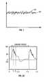
- FIG. 1is a graph illustrating the velocity of steady state turbulent flow as a function of time
- FIG. 2Ais a graph showing the velocity of the blood flow within an artery as a function of time
- FIG. 2Bis a graph illustrating the velocity of steady state turbulent flow under pulsatile conditions as a function of time, similar to arterial blood flow;
- FIG. 2Cis an elevation view of a turbulence inducing heat transfer element within an artery
- FIG. 3Ais a velocity profile diagram showing a typical steady state Poiseuillean flow driven by a constant pressure gradient
- FIG. 3Bis a velocity profile diagram showing blood flow velocity within an artery, averaged over the duration of the cardiac pulse;
- FIG. 3Cis a velocity profile diagram showing blood flow velocity within an artery, averaged over the duration of the cardiac pulse, after insertion of a smooth heat transfer element within the artery;
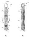
- FIG. 4is an elevation view of one embodiment of a heat transfer element according to the invention.
- FIG. 5is longitudinal section view of the heat transfer element of FIG. 4;
- FIG. 6is a transverse section view of the heat transfer element of FIG. 4;
- FIG. 7is a perspective view of the heat transfer element of FIG. 4 in use within a blood vessel
- FIG. 8is a cut-away perspective view of an alternative embodiment of a heat transfer element according to the invention.
- FIG. 9is a transverse section view of the heat transfer element of FIG. 8;
- FIG. 10is a schematic representation of the heat transfer element being used in one embodiment to cool the brain of a patient and to warm the blood returning from the brain in the jugular vein;
- FIG. 11is a schematic representation of the heat transfer element being used in one embodiment to cool the brain of a patient, while a warm saline solution is infused to warm the blood returning from the brain in the jugular vein;
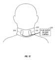
- FIG. 12is a schematic representation of one embodiment of an external warming device which can be used to warm the blood returning from an organ in a vein.
- a cooling elementmay be placed in the feeding artery of the organ to absorb heat from the blood flowing into the organ. This transfer of heat will cause a cooling of the selected organ.
- the cooling elementmust be small enough to fit within the feeding artery while still allowing a sufficient blood flow to reach the organ in order to avoid ischemic organ damage.
- a heat transfer element which selectively cools an organshould be capable of providing the necessary heat transfer rate to produce the desired cooling effect within the organ.
- the common carotid arterysupplies blood to the head and brain.
- the internal carotid arterybranches off of the common carotid to directly supply blood to the brain.
- the cooling elementis placed into the common carotid artery, or both the common carotid artery and the internal carotid artery.
- the internal diameter of the common carotid arteryranges from 6 to 8 mm and the length ranges from 80 to 120 mm.
- the cooling element residing in one of these arteriescannot be much larger than 4 mm in diameter in order to avoid occluding the vessel.
- the left and right internal jugular veinsreturn blood from the brain.
- the warming elementis placed in either or both the left and right internal jugular veins.
- a warm saline solutioncan be infused into the jugular vein, or external heat can be applied, either at or near the jugular veins or to the whole body.
- the intravascular heat transfer elementmay be flexible in order to be placed within the feeding artery or the vein of an organ.
- Feeding arterieslike the carotid artery, branch off the aorta at various levels. Subsidiary arteries continue to branch off the initial branches.
- the internal carotid arteryis a small diameter artery that branches off of the common carotid artery near the angle of the jaw. Because the heat transfer element is typically inserted into a peripheral artery, such as the femoral artery, and accesses the feeding artery by initially passing though a series of one or more of these branches, the flexibility of the heat transfer element is an important characteristic of the heat transfer element.
- the heat transfer elementis ideally constructed from a highly thermally conductive material such as metal in order to facilitate heat transfer.
- a highly thermally conductive materialincreases the heat transfer rate for a given temperature differential between the working fluid within the heat transfer element and the blood. This facilitates the use of a higher temperature coolant, or lower temperature warming fluid, within the heat transfer element, allowing safer working fluids, such as water, to be used.
- Highly thermally conductive materials, such as metalstend to be rigid. Therefore, the design of the heat transfer element should facilitate flexibility in an inherently inflexible material.
- the cooling elementshould absorb 75-175 Watts of heat when placed in one of the carotid arteries, in order to induce the desired cooling effect. It should be noted that smaller organs may have less blood flow in the supply artery and may require less heat transfer, such as 25 Watts.
- the magnitude of the heat transfer rateis proportional to the surface area of the heat transfer element, the temperature differential, and the heat transfer coefficient of the heat transfer element.
- the receiving artery or vein into which the heat transfer element is placedhas a limited diameter and length.
- surface area of the heat transfer elementmust be limited, to avoid significant obstruction of the artery or vein, and to allow the heat transfer element to easily pass through the vascular system.
- the cross sectional diameter of the heat transfer elementis limited to about 4 mm, and its length is limited to approximately 10 cm.
- the temperature differentialcan be increased by decreasing the surface temperature of the heat transfer element.
- the minimum allowable surface temperatureis limited by the characteristics of blood. Blood freezes at approximately 0° C. When the blood approaches freezing, ice emboli may form in the blood which may lodge downstream, causing serious ischemic injury. Furthermore, reducing the temperature of the blood also increases its viscosity, which results in a small decrease in the value of the convection heat transfer coefficient. In addition, increased viscosity of the blood may result in an increase in the pressure drop within the artery, thus, compromising the flow of blood to the brain. Given the above constraints, it is advantageous to limit the minimum allowable surface temperature of the cooling element to approximately 5° C. This results in a maximum temperature differential between the blood stream and the cooling element of approximately 32° C. For other physiological reasons, there are limits on the maximum allowable surface temperature of the warming element.
- FIG. 1is a graph illustrating steady state turbulent flow.
- the vertical axisis the velocity of the flow.
- the horizontal axisrepresents time.
- the average velocity of the turbulent flowis shown by a line 100 .
- the actual instantaneous velocity of the flowis shown by a curve 102 .
- FIG. 3Ais a velocity profile diagram showing a typical steady state Poiseuillean flow driven by a constant pressure gradient.
- the velocity of the fluid across the pipeis shown in FIG. 3A by the parabolic curve and corresponding velocity vectors.
- the velocity of the fluid in contact with the wall of the pipeis zero.
- the boundary layeris the region of the flow in contact with the pipe surface in which viscous stresses are dominant.
- the boundary layerdevelops until it includes the whole pipe, i.e., the boundary layer thickness in FIG. 3A is one half of the diameter of the pipe.
- the Reynolds numberthe ratio of inertial forces to viscous forces, can be used to characterize the level of turbulent kinetic energy existing in the flow.
- Reynolds numbersmust be greater than about 2300 to cause a transition from laminar to turbulent flow.
- the boundary layeris receptive to “tripping”. Tripping is a process by which a small perturbation in the boundary layer can create turbulent conditions. The receptivity of a boundary layer to “tripping” is proportional to the Reynolds number and is nearly zero for Reynolds numbers less than 2000.
- FIG. 2Ais a graph showing the velocity of the blood flow within an artery as a function of time.
- the beating heartprovides pulsatile flow with an approximate period of 0.5 to 1 second. This is known as the period of the cardiac cycle.
- the horizontal axis in FIG. 2Arepresents time in seconds and the vertical axis represents the average velocity of blood in centimeters per second.
- FIG. 3Bis a velocity profile diagram showing blood flow velocity within an artery averaged over the cardiac pulse. The majority of the flow within the artery has the same velocity. The boundary layer where the flow velocity decays from the free stream value to zero is very thin, typically 1 ⁇ 6 to ⁇ fraction (1/20) ⁇ of the diameter of the artery, as opposed to one half of the diameter of the artery in the Poiseuillean flow condition.
- the blood flow in the arteries of interestremains laminar over more than 80% of the cardiac cycle.
- the blood flowis turbulent from approximately time t 1 until time t 2 during a small portion of the descending systolic flow, which is less than 20% of the period of the cardiac cycle. If a heat transfer element is placed inside the artery, heat transfer will be facilitated during this short interval. However, to transfer the necessary heat to cool the brain, turbulent kinetic energy should be produced in the blood stream and sustained throughout the entire period of the cardiac cycle.
- FIG. 3Cis a velocity profile diagram showing blood flow velocity within an artery, averaged over the cardiac pulse, after insertion of a smooth heat transfer element within the artery.
- the diameter of the heat transfer elementis about one half of the diameter of the artery.
- Boundary layersdevelop adjacent to the heat transfer element as well as next to the walls of the artery. Each of these boundary layers has approximately the same thickness as the boundary layer which would have developed at the wall of the artery in the absence of the heat transfer element.
- the free stream flow regionis developed in an annular ring around the heat transfer element.
- One way to increase the heat transfer rateis to create a turbulent boundary layer on the heat transfer element surface.
- turbulence in the very thin boundary layerwill not produce sufficient kinetic energy to produce the necessary heat transfer rate. Therefore, to induce sufficient turbulent kinetic energy to increase the heat transfer rate sufficiently to cool the brain, and to subsequently warm the blood flow in the vein, a stirring mechanism, which abruptly changes the direction of velocity vectors, should be utilized. This can create high levels of turbulence intensity in the free stream, thereby sufficiently increasing the heat transfer rate.
- FIG. 2Bis a graph illustrating the velocity of continually turbulent flow under pulsatile conditions as a function of time, which would result in optimal heat transfer in arterial blood flow. Turbulent velocity fluctuations are seen throughout the cycle as opposed to the short interval of fluctuations seen in FIG. 2A between time t 1 and time t 2 . These velocity fluctuations are found within the free stream.
- the turbulence intensity shown in FIG. 2Bis at least 0.05. In other words, the instantaneous velocity fluctuations deviate from the mean velocity by at least 5%.
- turbulenceis created throughout the entire period of the cardiac cycle, the benefits of turbulence are also obtained if the turbulence is sustained for only 75%, 50% or even as low as 30% or 20% of the cardiac cycle.
- FIG. 2Cis a perspective view of such a turbulence inducing heat transfer element within an artery. Turbulent flow would be found at point 114 , in the free stream area.
- the abrupt changes in flow directionare achieved through the use of a series of two or more heat transfer segments, each comprised of one or more helical ridges. To affect the free stream, the depth of the helical ridge is larger than the thickness of the boundary layer which would develop if the heat transfer element had a smooth cylindrical surface.
- FIG. 4is an elevation view of one embodiment of a cooling element 14 according to the present invention.
- the heat transfer element 14is comprised of a series of elongated, articulated segments or modules 20 , 22 , 24 . Three such segments are shown in this embodiment, but two or more such segments could be used without departing from the spirit of the invention.
- a first elongated heat transfer segment 20is located at the proximal end of the heat transfer element 14 .
- a turbulence-inducing exterior surface of the segment 20comprises four parallel helical ridges 28 with four parallel helical grooves 26 therebetween.
- helical ridges 28 and the helical grooves 26 of the heat transfer segment 20have a left hand twist, referred to herein as a counter-clockwise spiral or helical rotation, as they proceed toward the distal end of the heat transfer segment 20 .
- the first heat transfer segment 20is coupled to a second elongated heat transfer segment 22 by a first bellows section 25 , which provides flexibility and compressibility.
- the second heat transfer segment 22comprises one or more helical ridges 32 with one or more helical grooves 30 therebetween.
- the ridges 32 and grooves 30have a right hand, or clockwise, twist as they proceed toward the distal end of the heat transfer segment 22 .
- the second heat transfer segment 22is coupled to a third elongated heat transfer segment 24 by a second bellows section 27 .
- the third heat transfer segment 24comprises one or more helical ridges 36 with one or more helical grooves 34 therebetween.
- the helical ridge 36 and the helical groove 34have a left hand, or counter-clockwise, twist as they proceed toward the distal end of the heat transfer segment 24 .
- successive heat transfer segments 20 , 22 , 24 of the heat transfer element 14alternate between having clockwise and counterclockwise helical twists.
- the actual left or right hand twist of any particular segmentis immaterial, as long as adjacent segments have opposite helical twist.
- a heat transfer element according to the present inventionmay be comprised of two, three, or more heat transfer segments.
- the bellows sections 25 , 27are formed from seamless and nonporous materials, such as metal, and therefore are impermeable to gas, which can be particularly important, depending on the type of working fluid which is cycled through the heat transfer element 14 .
- the structure of the bellows sections 25 , 27allows them to bend, extend and compress, which increases the flexibility of the heat transfer element 14 so that it is more readily able to navigate through blood vessels.
- the bellows sections 25 , 27also provide for axial compression of the heat transfer element 14 , which can limit the trauma when the distal end of the heat transfer element 14 abuts a blood vessel wall.
- the bellows sections 25 , 27are also able to tolerate cryogenic temperatures without a loss of performance.
- the exterior surfaces of the heat transfer element 14can be made from metal, and may comprise very high thermal conductivity materials such as nickel, thereby facilitating heat transfer.
- metalssuch as stainless steel, titanium, aluminum, silver, copper and the like, can be used, with or without an appropriate coating or treatment to enhance biocompatibility or inhibit clot formation.
- Suitable biocompatible coatingsinclude, e.g., gold, platinum or polymer paralyene.
- the heat transfer element 14may be manufactured by plating a thin layer of metal on a mandrel that has the appropriate pattern. In this way, the heat transfer element 14 may be manufactured inexpensively in large quantities, which is an important feature in a disposable medical device.
- the heat transfer element 14may dwell within the blood vessel for extended periods of time, such as 24-48 hours or even longer, it may be desirable to treat the surfaces of the heat transfer element 14 to avoid clot formation.
- One means by which to prevent thrombus formationis to bind an antithrombogenic agent to the surface of the heat transfer element 14 .
- heparinis known to inhibit clot formation and is also known to be useful as a biocoating.
- the surfaces of the heat transfer element 14may be bombarded with ions such as nitrogen. Bombardment with nitrogen can harden and smooth the surface and, thus prevent adherence of clotting factors to the surface.
- FIG. 5is a longitudinal sectional view of the heat transfer element 14 of an embodiment of the invention, taken along line 5 — 5 in FIG. 4 . Some interior contours are omitted for purposes of clarity.
- An inner tube 42creates an inner coaxial lumen 42 and an outer coaxial lumen 46 within the heat transfer element 14 .
- a working fluidsuch as saline or other aqueous solution may be circulated through the heat transfer element 14 . Fluid flows up a supply catheter into the inner coaxial lumen 40 . At the distal end of the heat transfer element 14 , the working fluid exits the inner coaxial lumen 40 and enters the outer lumen 46 .
- the tube 42may be formed as an insulating divider to thermally separate the inner lumen 40 from the outer lumen 46 .
- insulationmay be achieved by creating longitudinal air channels in the wall of the insulating tube 42 .
- the insulating tube 42may be constructed of a non-thermally conductive material like polytetrafluoroethylene or some other polymer.
- the same mechanisms that govern the heat transfer rate between the exterior surface 37 of the heat transfer element 14 and the bloodalso govern the heat transfer rate between the working fluid and the interior surface 38 of the heat transfer element 14 .
- the heat transfer characteristics of the interior surface 38are particularly important when using water, saline or other fluid which remains a liquid as the working fluid.
- Other coolantssuch as freon undergo nucleate boiling and create turbulence through a different mechanism.
- Salineis a safe working fluid, because it is non-toxic, and leakage of saline does not result in a gas embolism, which could occur with the use of boiling refrigerants.
- the working fluidcan be delivered to the cooling element 14 at a warmer temperature and still achieve the necessary cooling rate.
- the working fluidcan be delivered to the warming element 14 at a cooler temperature and still achieve the necessary warming rate.
- the catheter shaft diametercan be made smaller.
- the enhanced heat transfer characteristics of the interior surface of the heat transfer element 14also allow the working fluid to be delivered to the heat transfer element 14 at lower flow rates and lower pressures. High pressures may make the heat transfer element stiff and cause it to push against the wall of the blood vessel, thereby shielding part of the exterior surface 37 of the heat transfer element 14 from the blood. Because of the increased heat transfer characteristics achieved by the alternating helical ridges 28 , 32 , 36 , the pressure of the working fluid may be as low as 5 atmospheres, 3 atmospheres, 2 atmospheres or even less than 1 atmosphere.
- FIG. 6is a transverse sectional view of the heat transfer element 14 of the invention, taken at a location denoted by the line 6 — 6 in FIG. 4 .
- FIG. 6illustrates a five lobed embodiment, whereas FIG. 4 illustrates a four-lobed embodiment. As mentioned earlier, any number of lobes might be used.
- the inner coaxial lumen 40is defined by the insulating coaxial tube 42 .
- the outer lumen 46is defined by the exterior surface of the insulating coaxial tube 42 and the interior surface 38 of the heat transfer element 14 .
- the helical ridges 32 and helical grooves 30may be seen in FIG. 6 .
- the depth of the grooves, d ⁇is greater than the boundary layer thickness which would have developed if a cylindrical heat transfer element were introduced.
- the depth of the invaginations, d ⁇may be approximately equal to 1 mm if designed for use in the carotid artery.
- FIG. 6shows four ridges and four grooves, the number of ridges and grooves may vary.
- heat transfer elementswith 1, 2, 3, 4, 5, 6, 7, 8 or more ridges are specifically contemplated.
- FIG. 7is a perspective view of a heat transfer element 14 in use within a blood vessel, showing only one helical lobe per segment for purposes of clarity.
- the first helical heat transfer segment 20induces a counter-clockwise rotational inertia to the blood.
- the rotational direction of the inertiais reversed, causing turbulence within the blood.
- the rotational direction of the inertiais again reversed.
- the sudden changes in flow directionactively reorient and randomize the velocity vectors, thus ensuring turbulence throughout the bloodstream.
- the velocity vectors of the bloodbecome more random and, in some cases, become perpendicular to the axis of the artery.
- additional turbulenceis induced and turbulent motion is sustained throughout the duration of each pulse through the same mechanisms described above.
- the heat transfer element 14creates a turbulence intensity greater than about 0.05.
- the turbulence intensitymay be greater than 0.05, 0.06, 0.07 or up to 0.10 or 0.20 or greater.
- the heat transfer element 14has been designed to address all of the design criteria discussed above.
- the heat transfer element 14is flexible and is made of a highly conductive material. The flexibility is provided by a segmental distribution of bellows sections 25 , 27 which provide an articulating mechanism. Bellows have a known convoluted design which provides flexibility.
- the exterior surface area 37has been increased through the use of helical ridges 28 , 32 , 36 and helical grooves 26 , 30 , 34 . The ridges also allow the heat transfer element 14 to maintain a relatively atraumatic profile, thereby minimizing the possibility of damage to the vessel wall.
- the heat transfer element 14has been designed to promote turbulent kinetic energy both internally and externally.
- the modular or segmental designallows the direction of the invaginations to be reversed between segments.
- the alternating helical rotationscreate an alternating flow that results in mixing the blood in a manner analogous to the mixing action created by the rotor of a washing machine that switches directions back and forth. This mixing action is intended to promote high level turbulent kinetic energy to enhance the heat transfer rate.
- the alternating helical designalso causes beneficial mixing, or turbulent kinetic energy, of the working fluid flowing internally.
- FIG. 8is a cut-away perspective view of an alternative embodiment of a heat transfer element 50 .
- An external surface 52 of the heat transfer element 50is covered with a series of axially staggered protrusions 54 .
- the staggered nature of the outer protrusions 54is readily seen with reference to FIG. 9 which is a transverse cross-sectional view taken at a location denoted by the line 9 — 9 in FIG. 8 .
- the height, d pof the staggered outer protrusions 54 is greater than the thickness of the boundary layer which would develop if a smooth heat transfer element had been introduced into the blood stream.
- a working fluidis circulated up through an inner coaxial lumen 56 defined by an insulating coaxial tube 58 to a distal tip of the heat transfer element 50 .
- the working fluidthen traverses an outer coaxial lumen 60 in order to transfer heat to the exterior surface 52 of the heat transfer element 50 .
- the inside surface of the heat transfer element 50is similar to the exterior surface 52 , in order to induce turbulent flow of the working fluid.
- the inner protrusionscan be aligned with the outer protrusions 54 , as shown in FIG. 9, or they can be offset from the outer protrusions 54 , as shown in FIG. 8 .
- FIG. 10is a schematic representation of the invention being used to cool the brain of a patient, and to warm the blood returning from the brain in the jugular vein.
- the selective organ hypothermia apparatus shown in FIG. 10includes a first working fluid supply 10 , preferably supplying a chilled liquid such as water, alcohol or a halogenated hydrocarbon, a first supply catheter 12 and the cooling element 14 .
- the first supply catheter 12has a coaxial construction.
- An inner coaxial lumen within the first supply catheter 12receives coolant from the first working fluid supply 10 .
- the coolanttravels the length of the first supply catheter 12 to the cooling element 14 which serves as the cooling tip of the catheter.
- the first supply catheter 12is a flexible catheter having a diameter sufficiently small to allow its distal end to be inserted percutaneously into an accessible artery such as the femoral artery of a patient as shown in FIG. 10 .
- the first supply catheter 12is sufficiently long to allow the cooling element 14 at the distal end of the first supply catheter 12 to be passed through the vascular system of the patient and placed in the internal carotid artery or other small artery. The method of inserting the catheter into the patient and routing the cooling element 14 into a selected artery is well known in the art.
- working fluid supply 10is shown as an exemplary cooling device, other devices and working fluids may be used.
- freon, perfluorocarbon, water, or salinemay be used, as well as other such coolants.
- the cooling elementcan absorb or provide over 75 Watts of heat to the blood stream and may absorb or provide as much as 100 Watts, 150 Watts, 170 Watts or more.
- a cooling element with a diameter of 4 mm and a length of approximately 10 cm using ordinary saline solution chilled so that the surface temperature of the heat transfer element is approximately 5° C. and pressurized at 2 atmospherescan absorb about 100 Watts of energy from the bloodstream.
- Smaller geometry heat transfer elementsmay be developed for use with smaller organs which provide 60 Watts, 50 Watts, 25 Watts or less of heat transfer.
- FIG. 10also shows a second working fluid supply 110 , preferably supplying a warm liquid such as water, a second supply catheter 112 and the warming element 114 , which can be similar or identical to the cooling element 14 .
- the second supply catheter 112has a coaxial construction.
- An inner coaxial lumen within the second supply catheter 112receives warm fluid from the second working fluid supply 110 .
- the fluidtravels the length of the second supply catheter 112 to the warming element 114 which serves as the warming tip of the catheter.
- the fluidexits the insulated interior lumen and traverses the length of the warming element 114 in order to increase the temperature of the warming element 114 .
- the fluidthen traverses an outer lumen of the second supply catheter 112 so that it may be disposed of or recirculated.
- the second supply catheter 112is a flexible catheter having a diameter sufficiently small to allow its distal end to be inserted percutaneously into an accessible vein such as the left internal jugular vein of a patient as shown in FIG. 10 .
- the warming element 114can be an electrical resistance heater controlled by a controller represented by item 110 .
- the patientis initially assessed, resuscitated, and stabilized.
- the procedureis carried out in an angiography suite or surgical suite equipped with fluoroscopy.
- a carotid duplex (doppler/ultrasound) scancan quickly and non-invasively make this determinations.
- the ideal location for placement of the catheteris in the left carotid so this may be scanned first. If disease is present, then the right carotid artery can be assessed. This test can be used to detect the presence of proximal common carotid lesions by observing the slope of the systolic upstroke and the shape of the pulsation. Although these lesions are rare, they could inhibit the placement of the catheter.
- Peak blood flow velocities in the internal carotidcan determine the presence of internal carotid artery lesions. Although the catheter is placed proximally to such lesions, the catheter may exacerbate the compromised blood flow created by these lesions. Peak systolic velocities greater that 130 cm/sec and peak diastolic velocities >100 cm/sec in the internal indicate the presence of at least 70% stenosis. Stenosis of 70% or more may warrant the placement of a stent to open up the internal artery diameter.
- the ultrasoundcan also be used to determine the vessel diameter and the blood flow and the catheter with the appropriately sized heat transfer element could be selected.
- the patients inguinal regionis sterilely prepped and infiltrated with lidocaine.
- the femoral arteryis cannulated and a guide wire may be inserted to the desired carotid artery. Placement of the guide wire is confirmed with fluoroscopy.
- An angiographic cathetercan be fed over the wire and contrast media injected into the artery to further to assess the anatomy of the carotid.
- the femoral arteryis cannulated and a 10-12.5 french (f) introducer sheath is placed.
- a guide catheteris placed into the desired common carotid artery. If a guiding catheter is placed, it can be used to deliver contrast media directly to further assess carotid anatomy.
- a 10 f-12 f (3.3-4.0 mm) (approximate) cooling catheteris subsequently filled with saline and all air bubbles are removed.
- the cooling catheteris placed into the carotid artery via the guiding catheter or over the guidewire. Placement is confirmed with fluoroscopy.
- the cooling catheter tipis shaped (angled or curved approximately 45 degrees), and the cooling catheter shaft has sufficient pushability and torqueability to be placed in the carotid without the aid of a guide wire or guide catheter.
- the cooling catheteris connected to a pump circuit also filled with saline and free from air bubbles.
- the pump circuithas a heat exchange section that is immersed into a water bath and tubing that is connected to a peristaltic pump. The water bath is chilled to approximately 0° C.
- Coolingis initiated by starting the pump mechanism.
- the saline within the cooling catheteris circulated at 5 cc/sec.
- the salinetravels through the heat exchanger in the chilled water bath and is cooled to approximately 1° C.
- the salineis warmed to approximately 5-7° C. as it travels along the inner lumen of the catheter shaft to the end of the heat transfer element.
- the salinethen flows back through the heat transfer element in contact with the inner metallic surface.
- the salineis further warmed in the heat transfer element to 12-15° C, and in the process, heat is absorbed from the blood, cooling the blood to 30° C. to 32° C.
- the warmed salinetravels back down the outer lumen of the catheter shaft and back to the chilled water bath where it is cooled to 1° C.
- the pressure drops along the length of the circuitare estimated to be 2-3 atmospheres.
- the coolingcan be adjusted by increasing or decreasing the flow rate of the saline. Monitoring of the temperature drop of the saline along the heat transfer element will allow the flow to be adjusted to maintain the desired cooling effect.
- the catheteris left in place to provide cooling for 12 to 24 hours.
- warm salinecan be circulated to promote warming of the brain at the end of the therapeutic cooling period.
- a warm saline solutioncan be infused into the jugular vein from a saline supply 210 , via an intravenous catheter 212 , as shown in FIG. 11 . This is advantageous since saline drips are often necessary anyway as maintenance fluids (1000 to 2500 cc/day). As yet another alternative, warming can be applied externally to the patient.
- the means of warmingcan be a heating blanket applied to the whole body, or localized heating of veins returning from the organ being cooled.
- FIG. 12shows a neck brace 312 being used to immobilize the head of the patient. Immobilization of the head can be necessary to prevent movement of the cooling element, or to prevent puncture of the feeding artery by the cooling element.
- the neck brace 312can have one or more warming elements 314 placed directly over the left and right internal jugular veins, to heat the blood flowing in the jugular veins, through the skin.
- the warming elements 314can be warmed by circulating fluid, or they can be electrical resistance heaters. Temperature control can be maintained by a working fluid supply or controller 310 .
Landscapes
- Health & Medical Sciences (AREA)
- Vascular Medicine (AREA)
- Thermal Sciences (AREA)
- Engineering & Computer Science (AREA)
- Biomedical Technology (AREA)
- Heart & Thoracic Surgery (AREA)
- Physics & Mathematics (AREA)
- Life Sciences & Earth Sciences (AREA)
- Animal Behavior & Ethology (AREA)
- General Health & Medical Sciences (AREA)
- Public Health (AREA)
- Veterinary Medicine (AREA)
- Thermotherapy And Cooling Therapy Devices (AREA)
Abstract
Description
Claims (10)
Priority Applications (1)
| Application Number | Priority Date | Filing Date | Title |
|---|---|---|---|
| US09/871,145US6599312B2 (en) | 1998-03-24 | 2001-05-29 | Isolated selective organ cooling apparatus |
Applications Claiming Priority (5)
| Application Number | Priority Date | Filing Date | Title |
|---|---|---|---|
| US09/047,012US5957963A (en) | 1998-01-23 | 1998-03-24 | Selective organ hypothermia method and apparatus |
| US09/052,545US6231595B1 (en) | 1998-03-31 | 1998-03-31 | Circulating fluid hypothermia method and apparatus |
| US09/103,342US6096068A (en) | 1998-01-23 | 1998-06-23 | Selective organ cooling catheter and method of using the same |
| US29253299A | 1999-04-15 | 1999-04-15 | |
| US09/871,145US6599312B2 (en) | 1998-03-24 | 2001-05-29 | Isolated selective organ cooling apparatus |
Related Parent Applications (1)
| Application Number | Title | Priority Date | Filing Date |
|---|---|---|---|
| US29253299AContinuation | 1998-01-23 | 1999-04-15 |
Publications (2)
| Publication Number | Publication Date |
|---|---|
| US20020002394A1 US20020002394A1 (en) | 2002-01-03 |
| US6599312B2true US6599312B2 (en) | 2003-07-29 |
Family
ID=46277672
Family Applications (2)
| Application Number | Title | Priority Date | Filing Date |
|---|---|---|---|
| US09/871,145Expired - LifetimeUS6599312B2 (en) | 1998-03-24 | 2001-05-29 | Isolated selective organ cooling apparatus |
| US10/322,337Expired - Fee RelatedUS6740109B2 (en) | 1998-01-23 | 2002-12-16 | Isolated selective organ cooling method |
Family Applications After (1)
| Application Number | Title | Priority Date | Filing Date |
|---|---|---|---|
| US10/322,337Expired - Fee RelatedUS6740109B2 (en) | 1998-01-23 | 2002-12-16 | Isolated selective organ cooling method |
Country Status (1)
| Country | Link |
|---|---|
| US (2) | US6599312B2 (en) |
Cited By (36)
| Publication number | Priority date | Publication date | Assignee | Title |
|---|---|---|---|---|
| US20050131501A1 (en)* | 2003-12-15 | 2005-06-16 | Rowland Robert A.Iii | Apparatus and method for prevention and treatment of infection |
| US6942686B1 (en)* | 2002-11-01 | 2005-09-13 | Coaxia, Inc. | Regulation of cerebral blood flow by temperature change-induced vasodilatation |
| US20060025755A1 (en)* | 2004-07-30 | 2006-02-02 | Jaime Landman | Surgical cooling system and method |
| US20060052854A1 (en)* | 2000-06-05 | 2006-03-09 | Mats Allers | Cerebral temperature control |
| US7056282B2 (en) | 2002-12-23 | 2006-06-06 | Medtronic Emergency Response Systems, Inc. | Coolant control for rapid induction of mild hypothermia |
| US7087075B2 (en) | 2002-09-30 | 2006-08-08 | Medtronic Emergency Response Systems, Inc. | Feedback system for rapid induction of mild hypothermia |
| US20060190066A1 (en)* | 2005-02-23 | 2006-08-24 | Worthen William J | System and method for bringing hypothermia rapidly onboard |
| US7179279B2 (en) | 2002-09-30 | 2007-02-20 | Medtronic Physio Control Corp. | Rapid induction of mild hypothermia |
| US7181927B2 (en) | 2005-07-01 | 2007-02-27 | Alsius Corporation | Primary heat exchanger for patient temperature control |
| US7425216B2 (en) | 2005-03-01 | 2008-09-16 | Alsius Corporation | System and method for treating cardiac arrest and myocardial infarction |
| US20100198319A1 (en)* | 2007-07-04 | 2010-08-05 | Arad Eliahu | System and method for manipulating a temperature of a patient |
| US7822485B2 (en) | 2006-09-25 | 2010-10-26 | Zoll Circulation, Inc. | Method and apparatus for spinal cooling |
| US20100324635A1 (en)* | 2008-01-25 | 2010-12-23 | Neurosave, Inc. | Rapid cooling of body and/or brain by irrigating with a cooling liquid |
| US7857781B2 (en) | 1998-04-21 | 2010-12-28 | Zoll Circulation, Inc. | Indwelling heat exchange catheter and method of using same |
| US7867266B2 (en) | 2006-11-13 | 2011-01-11 | Zoll Circulation, Inc. | Temperature management system with assist mode for use with heart-lung machine |
| US20110040224A1 (en)* | 2005-09-28 | 2011-02-17 | Life Core Technologies, Llc | Cervical immobilization collar with arterial cooling elements and method of using the same |
| US20110040223A1 (en)* | 2005-09-28 | 2011-02-17 | Life Core Technologies Llc | Cervical immobilization collar with arterial cooling elements |
| US7892270B2 (en) | 2006-11-21 | 2011-02-22 | Zoll Circulation Inc. | Temperature management system and method for burn patients |
| US7892269B2 (en) | 2005-04-18 | 2011-02-22 | Zoll Circulation, Inc. | External heat exchange pad for patient |
| US20110046527A1 (en)* | 2005-09-28 | 2011-02-24 | Life Core Technologies, Llc | Arterial cooling elements for use with a cervical immobilization collar |
| US7951182B2 (en) | 2005-07-14 | 2011-05-31 | Zoll Circulation, Inc. | System and method for leak detection in external cooling pad |
| US8128595B2 (en) | 1998-04-21 | 2012-03-06 | Zoll Circulation, Inc. | Method for a central venous line catheter having a temperature control system |
| US8236038B2 (en) | 2006-04-20 | 2012-08-07 | University Of Pittsburgh-Of The Commonwealth System Of Higher Education | Method and apparatus of noninvasive, regional brain thermal stimuli for the treatment of neurological disorders |
| US8353893B2 (en) | 2007-03-07 | 2013-01-15 | Zoll Circulation, Inc. | System and method for rapidly cooling cardiac arrest patient |
| US8425583B2 (en) | 2006-04-20 | 2013-04-23 | University of Pittsburgh—of the Commonwealth System of Higher Education | Methods, devices and systems for treating insomnia by inducing frontal cerebral hypothermia |
| US20130245407A1 (en)* | 2005-09-28 | 2013-09-19 | Cryothermic Systems | Cervical Immobilization Collar With Arterial Cooling Elements and Method of Using The Same |
| US20130245521A1 (en)* | 2005-09-28 | 2013-09-19 | Cryothermic Systems, Inc. | Cervical Immobilization Collar With Arterial Cooling Elements and Method of Using the Same |
| US20130253395A1 (en)* | 2005-09-28 | 2013-09-26 | Cryothermic Systems, Inc. | Arterial cooling elements for use with a cervical immobilization collar |
| US9211212B2 (en) | 2006-04-20 | 2015-12-15 | Cerêve, Inc. | Apparatus and method for modulating sleep |
| US9492313B2 (en) | 2006-04-20 | 2016-11-15 | University Of Pittsburgh - Of The Commonwealth System Of Higher Education | Method and apparatus of noninvasive, regional brain thermal stimuli for the treatment of neurological disorders |
| US9737692B2 (en) | 2007-05-18 | 2017-08-22 | Zoll Circulation, Inc. | System and method for effecting non-standard fluid line connections |
| US10058674B2 (en) | 2013-01-02 | 2018-08-28 | Ebb Therapeutics, Inc. | Systems for enhancing sleep |
| US11464671B2 (en) | 2017-04-07 | 2022-10-11 | Palmera Medical, Inc. | Therapeutic organ cooling |
| US11684510B2 (en) | 2006-04-20 | 2023-06-27 | University of Pittsburgh—of the Commonwealth System of Higher Education | Noninvasive, regional brain thermal stimuli for the treatment of neurological disorders |
| US11813194B2 (en) | 2017-03-06 | 2023-11-14 | Board Of Regents, The University Of Texas System | Water perfusion heat exchange pad for control of skin temperature |
| US12290640B2 (en) | 2006-04-20 | 2025-05-06 | University of Pittsburgh—of the Commonwealth System of Higher Education | Noninvasive, regional brain thermal stimulation for inducing relaxation |
Families Citing this family (62)
| Publication number | Priority date | Publication date | Assignee | Title |
|---|---|---|---|---|
| US6991645B2 (en)* | 1998-01-23 | 2006-01-31 | Innercool Therapies, Inc. | Patient temperature regulation method and apparatus |
| US6312452B1 (en) | 1998-01-23 | 2001-11-06 | Innercool Therapies, Inc. | Selective organ cooling catheter with guidewire apparatus and temperature-monitoring device |
| US7371254B2 (en)* | 1998-01-23 | 2008-05-13 | Innercool Therapies, Inc. | Medical procedure |
| US6231595B1 (en) | 1998-03-31 | 2001-05-15 | Innercool Therapies, Inc. | Circulating fluid hypothermia method and apparatus |
| US6261312B1 (en)* | 1998-06-23 | 2001-07-17 | Innercool Therapies, Inc. | Inflatable catheter for selective organ heating and cooling and method of using the same |
| US6379378B1 (en) | 2000-03-03 | 2002-04-30 | Innercool Therapies, Inc. | Lumen design for catheter |
| US6325818B1 (en) | 1999-10-07 | 2001-12-04 | Innercool Therapies, Inc. | Inflatable cooling apparatus for selective organ hypothermia |
| US6843800B1 (en) | 1998-01-23 | 2005-01-18 | Innercool Therapies, Inc. | Patient temperature regulation method and apparatus |
| US6471717B1 (en)* | 1998-03-24 | 2002-10-29 | Innercool Therapies, Inc. | Selective organ cooling apparatus and method |
| US6585752B2 (en) | 1998-06-23 | 2003-07-01 | Innercool Therapies, Inc. | Fever regulation method and apparatus |
| US6383210B1 (en)* | 2000-06-02 | 2002-05-07 | Innercool Therapies, Inc. | Method for determining the effective thermal mass of a body or organ using cooling catheter |
| US6096068A (en) | 1998-01-23 | 2000-08-01 | Innercool Therapies, Inc. | Selective organ cooling catheter and method of using the same |
| US6464716B1 (en) | 1998-01-23 | 2002-10-15 | Innercool Therapies, Inc. | Selective organ cooling apparatus and method |
| US6599312B2 (en) | 1998-03-24 | 2003-07-29 | Innercool Therapies, Inc. | Isolated selective organ cooling apparatus |
| US6576002B2 (en) | 1998-03-24 | 2003-06-10 | Innercool Therapies, Inc. | Isolated selective organ cooling method and apparatus |
| US6685732B2 (en) | 1998-03-31 | 2004-02-03 | Innercool Therapies, Inc. | Method and device for performing cooling- or cryo-therapies for, e.g., angioplasty with reduced restenosis or pulmonary vein cell necrosis to inhibit atrial fibrillation employing microporous balloon |
| US7291144B2 (en) | 1998-03-31 | 2007-11-06 | Innercool Therapies, Inc. | Method and device for performing cooling- or cryo-therapies for, e.g., angioplasty with reduced restenosis or pulmonary vein cell necrosis to inhibit atrial fibrillation |
| US6602276B2 (en) | 1998-03-31 | 2003-08-05 | Innercool Therapies, Inc. | Method and device for performing cooling- or cryo-therapies for, e.g., angioplasty with reduced restenosis or pulmonary vein cell necrosis to inhibit atrial fibrillation |
| US6905494B2 (en) | 1998-03-31 | 2005-06-14 | Innercool Therapies, Inc. | Method and device for performing cooling- or cryo-therapies for, e.g., angioplasty with reduced restenosis or pulmonary vein cell necrosis to inhibit atrial fibrillation employing tissue protection |
| US7001378B2 (en)* | 1998-03-31 | 2006-02-21 | Innercool Therapies, Inc. | Method and device for performing cooling or cryo-therapies, for, e.g., angioplasty with reduced restenosis or pulmonary vein cell necrosis to inhibit atrial fibrillation employing tissue protection |
| US6869440B2 (en) | 1999-02-09 | 2005-03-22 | Innercool Therapies, Inc. | Method and apparatus for patient temperature control employing administration of anti-shivering agents |
| US6830581B2 (en)* | 1999-02-09 | 2004-12-14 | Innercool Therspies, Inc. | Method and device for patient temperature control employing optimized rewarming |
| US6648906B2 (en) | 2000-04-06 | 2003-11-18 | Innercool Therapies, Inc. | Method and apparatus for regulating patient temperature by irrigating the bladder with a fluid |
| US6719723B2 (en)* | 2000-12-06 | 2004-04-13 | Innercool Therapies, Inc. | Multipurpose catheter assembly |
| US6450987B1 (en) | 2001-02-01 | 2002-09-17 | Innercool Therapies, Inc. | Collapsible guidewire lumen |
| WO2003015672A1 (en)* | 2001-08-15 | 2003-02-27 | Innercool Therapies, Inc. | Method and apparatus for patient temperature control employing administration of anti-shivering |
| CA2411569A1 (en)* | 2002-11-12 | 2004-05-12 | Ross E. Mantle | Medical device for the extravascular recirculation of fluid in body cavities at controlled temperature and pressure |
| US7001418B2 (en)* | 2003-04-30 | 2006-02-21 | Alsius Corporation | Intravascular heat exchange catheter with insulated coolant tubes |
| US20060136023A1 (en)* | 2004-08-26 | 2006-06-22 | Dobak John D Iii | Method and apparatus for patient temperature control employing administration of anti-shivering agents |
| US20060064146A1 (en)* | 2004-09-17 | 2006-03-23 | Collins Kenneth A | Heating/cooling system for indwelling heat exchange catheter |
| US8672988B2 (en)* | 2004-10-22 | 2014-03-18 | Medtronic Cryocath Lp | Method and device for local cooling within an organ using an intravascular device |
| US20060190062A1 (en)* | 2005-02-23 | 2006-08-24 | Worthen William J | System and method for reducing shivering when using external cooling pads |
| US20060276864A1 (en)* | 2005-06-03 | 2006-12-07 | Alsius Corporation | Systems and methods for sensing patient temperature in temperature management system |
| US20060293732A1 (en)* | 2005-06-27 | 2006-12-28 | Collins Kenneth A | Thermoelectric cooler (TEC) heat exchanger for intravascular heat exchange catheter |
| WO2008124643A1 (en)* | 2007-04-05 | 2008-10-16 | Velomedix, Inc. | Device and method for safe access to a body cavity |
| CA2684807A1 (en) | 2007-04-05 | 2008-10-16 | Velomedix, Inc. | Automated therapy system and method |
| WO2009009540A1 (en)* | 2007-07-09 | 2009-01-15 | Velomedix, Inc. | Hypothermia devices and methods |
| AU2009313320A1 (en)* | 2008-11-07 | 2010-05-14 | Velomedix, Inc. | Devices and methods for monitoring core temperature and an intraperitoneal parameter |
| AU2010210385A1 (en)* | 2009-02-06 | 2011-08-18 | Velomedix, Inc. | Method and apparatus for inducing therapeutic hypothermia |
| US8608696B1 (en) | 2009-02-24 | 2013-12-17 | North Carolina State University | Rapid fluid cooling devices and methods for cooling fluids |
| US9622670B2 (en) | 2010-07-09 | 2017-04-18 | Potrero Medical, Inc. | Method and apparatus for pressure measurement |
| US9283110B2 (en) | 2011-09-20 | 2016-03-15 | Zoll Circulation, Inc. | Patient temperature control catheter with outer sleeve cooled by inner sleeve |
| US9314370B2 (en) | 2011-09-28 | 2016-04-19 | Zoll Circulation, Inc. | Self-centering patient temperature control catheter |
| US10045881B2 (en) | 2011-09-28 | 2018-08-14 | Zoll Circulation, Inc. | Patient temperature control catheter with helical heat exchange paths |
| US9259348B2 (en) | 2011-09-28 | 2016-02-16 | Zoll Circulation, Inc. | Transatrial patient temperature control catheter |
| US8888832B2 (en) | 2011-09-28 | 2014-11-18 | Zoll Circulation, Inc. | System and method for doubled use of patient temperature control catheter |
| US9433528B2 (en) | 2012-09-28 | 2016-09-06 | Zoll Circulation, Inc. | Intravascular heat exchange catheter with rib cage-like coolant path |
| US9241827B2 (en) | 2012-09-28 | 2016-01-26 | Zoll Circulation, Inc. | Intravascular heat exchange catheter with multiple spaced apart discrete coolant loops |
| US9717625B2 (en) | 2012-09-28 | 2017-08-01 | Zoll Circulation, Inc. | Intravascular heat exchange catheter with non-round coiled coolant path |
| US9801756B2 (en) | 2012-09-28 | 2017-10-31 | Zoll Circulation, Inc. | Intravascular heat exchange catheter and system with RFID coupling |
| US9474644B2 (en) | 2014-02-07 | 2016-10-25 | Zoll Circulation, Inc. | Heat exchange system for patient temperature control with multiple coolant chambers for multiple heat exchange modalities |
| US10792185B2 (en) | 2014-02-14 | 2020-10-06 | Zoll Circulation, Inc. | Fluid cassette with polymeric membranes and integral inlet and outlet tubes for patient heat exchange system |
| US10500088B2 (en) | 2014-02-14 | 2019-12-10 | Zoll Circulation, Inc. | Patient heat exchange system with two and only two fluid loops |
| US11033424B2 (en) | 2014-02-14 | 2021-06-15 | Zoll Circulation, Inc. | Fluid cassette with tensioned polymeric membranes for patient heat exchange system |
| US9784263B2 (en) | 2014-11-06 | 2017-10-10 | Zoll Circulation, Inc. | Heat exchange system for patient temperature control with easy loading high performance peristaltic pump |
| US11359620B2 (en) | 2015-04-01 | 2022-06-14 | Zoll Circulation, Inc. | Heat exchange system for patient temperature control with easy loading high performance peristaltic pump |
| US11213423B2 (en) | 2015-03-31 | 2022-01-04 | Zoll Circulation, Inc. | Proximal mounting of temperature sensor in intravascular temperature management catheter |
| US10537465B2 (en) | 2015-03-31 | 2020-01-21 | Zoll Circulation, Inc. | Cold plate design in heat exchanger for intravascular temperature management catheter and/or heat exchange pad |
| US10022265B2 (en) | 2015-04-01 | 2018-07-17 | Zoll Circulation, Inc. | Working fluid cassette with hinged plenum or enclosure for interfacing heat exchanger with intravascular temperature management catheter |
| US11337851B2 (en) | 2017-02-02 | 2022-05-24 | Zoll Circulation, Inc. | Devices, systems and methods for endovascular temperature control |
| US11116657B2 (en) | 2017-02-02 | 2021-09-14 | Zoll Circulation, Inc. | Devices, systems and methods for endovascular temperature control |
| US11185440B2 (en) | 2017-02-02 | 2021-11-30 | Zoll Circulation, Inc. | Devices, systems and methods for endovascular temperature control |
Citations (201)
| Publication number | Priority date | Publication date | Assignee | Title |
|---|---|---|---|---|
| US2308484A (en) | 1939-01-16 | 1943-01-19 | Davol Rubber Co | Catheter |
| US2374609A (en) | 1945-04-24 | Heating apparatus | ||
| US2615686A (en) | 1948-05-29 | 1952-10-28 | Servel Inc | Heat transfer device |
| US2672032A (en) | 1951-10-19 | 1954-03-16 | Towse Robert Albert Edward | Carcass freezing device |
| US2913009A (en) | 1956-07-16 | 1959-11-17 | Calumet & Hecla | Internal and internal-external surface heat exchange tubing |
| US3125096A (en) | 1964-03-17 | Compressor | ||
| US3298371A (en) | 1965-02-11 | 1967-01-17 | Arnold S J Lee | Freezing probe for the treatment of tissue, especially in neurosurgery |
| US3425419A (en) | 1964-08-08 | 1969-02-04 | Angelo Actis Dato | Method of lowering and raising the temperature of the human body |
| US3504674A (en) | 1966-12-22 | 1970-04-07 | Emil S Swenson | Method and apparatus for performing hypothermia |
| US3612175A (en) | 1969-07-01 | 1971-10-12 | Olin Corp | Corrugated metal tubing |
| US3839621A (en)* | 1972-08-11 | 1974-10-01 | H Hariu | Body heating device |
| US3865116A (en) | 1973-04-09 | 1975-02-11 | Harold W Brooks | Method of controlling tissue hypothermia |
| US3888259A (en) | 1973-08-21 | 1975-06-10 | Robert C Miley | Hypothermia system |
| US3971383A (en) | 1974-05-07 | 1976-07-27 | Erbe Elektromedizin Kg | Cryogenic surgical instrument |
| US4038519A (en) | 1973-11-15 | 1977-07-26 | Rhone-Poulenc S.A. | Electrically heated flexible tube having temperature measuring probe |
| US4149541A (en)* | 1977-10-06 | 1979-04-17 | Moore-Perk Corporation | Fluid circulating pad |
| US4153048A (en) | 1977-09-14 | 1979-05-08 | Cleveland Clinic Foundation | Thermodilution catheter and method |
| US4190033A (en) | 1977-02-23 | 1980-02-26 | Foti Thomas M | Closed flow caloric test method |
| US4231425A (en) | 1978-02-27 | 1980-11-04 | Engstrom William R | Extracorporeal circuit blood heat exchanger |
| SU806029A1 (en) | 1978-05-03 | 1981-02-23 | Иркутский Государственный Медицинс-Кий Институт | Method of monitoring degree of perfused cooling of brain |
| US4275734A (en) | 1977-08-12 | 1981-06-30 | Valleylab, Inc. | Cryosurgical apparatus and method |
| US4298006A (en) | 1980-04-30 | 1981-11-03 | Research Against Cancer, Inc. | Systemic hyperthermia with improved temperature sensing apparatus and method |
| US4318722A (en) | 1980-04-09 | 1982-03-09 | Gerald Altman | Infrared radiation cooler for producing physiologic conditions such as a comfort or hypothermia |
| US4323071A (en) | 1978-04-24 | 1982-04-06 | Advanced Catheter Systems, Inc. | Vascular guiding catheter assembly and vascular dilating catheter assembly and a combination thereof and methods of making the same |
| FR2447406B1 (en) | 1979-01-26 | 1982-11-12 | Nisshin Steel Co Ltd | |
| US4427009A (en) | 1981-06-30 | 1984-01-24 | Minnesota Mining And Manufacturing Company | Integrated cardioplegia delivery system |
| US4445500A (en) | 1982-03-03 | 1984-05-01 | Thomas Jefferson University | Stroke treatment utilizing extravascular circulation of oxygenated synthetic nutrients to treat tissue hypoxic and ischemic disorders |
| US4483341A (en) | 1982-12-09 | 1984-11-20 | Atlantic Richfield Company | Therapeutic hypothermia instrument |
| US4502286A (en) | 1982-08-11 | 1985-03-05 | Hitachi, Ltd. | Constant pressure type boiling cooling system |
| US4569355A (en) | 1982-05-28 | 1986-02-11 | Hemodynamics Technology, Inc. | Method and apparatus for monitoring and diagnosing peripheral blood flow |
| US4581017A (en) | 1983-03-07 | 1986-04-08 | Harvinder Sahota | Catheter systems |
| US4602642A (en) | 1984-10-23 | 1986-07-29 | Intelligent Medical Systems, Inc. | Method and apparatus for measuring internal body temperature utilizing infrared emissions |
| US4655746A (en) | 1985-12-02 | 1987-04-07 | Target Therapeutics | Catheter device |
| US4672962A (en) | 1983-09-28 | 1987-06-16 | Cordis Corporation | Plaque softening method |
| US4745922A (en) | 1986-07-11 | 1988-05-24 | Taylor Kenneth G | Cervical heat transfer and immobilization device |
| US4748979A (en) | 1985-10-07 | 1988-06-07 | Cordis Corporation | Plaque resolving device |
| US4750493A (en) | 1986-02-28 | 1988-06-14 | Brader Eric W | Method of preventing brain damage during cardiac arrest, CPR or severe shock |
| US4762129A (en) | 1984-11-23 | 1988-08-09 | Tassilo Bonzel | Dilatation catheter |
| US4762130A (en) | 1987-01-15 | 1988-08-09 | Thomas J. Fogarty | Catheter with corkscrew-like balloon |
| US4781799A (en) | 1986-12-08 | 1988-11-01 | Xerox Corporation | Electroforming apparatus and process |
| US4820349A (en) | 1987-08-21 | 1989-04-11 | C. R. Bard, Inc. | Dilatation catheter with collapsible outer diameter |
| US4860744A (en) | 1987-11-02 | 1989-08-29 | Raj K. Anand | Thermoelectrically controlled heat medical catheter |
| US4883455A (en) | 1988-09-13 | 1989-11-28 | Minnesota Mining And Manufacturing Company | Cardioplegia administration set |
| US4894164A (en) | 1986-10-30 | 1990-01-16 | Fresenius Ag | Apparatus for treating blood in an extracorporeal circuit |
| US4904237A (en) | 1988-05-16 | 1990-02-27 | Janese Woodrow W | Apparatus for the exchange of cerebrospinal fluid and a method of treating brain and spinal cord injuries |
| US4920963A (en) | 1986-02-28 | 1990-05-01 | Brader Eric W | Apparatus for preventing brain damage during cardiac arrest, CPR or severe shock |
| US4951677A (en) | 1988-03-21 | 1990-08-28 | Prutech Research And Development Partnership Ii | Acoustic imaging catheter and the like |
| US4964409A (en) | 1989-05-11 | 1990-10-23 | Advanced Cardiovascular Systems, Inc. | Flexible hollow guiding member with means for fluid communication therethrough |
| US5000734A (en) | 1988-02-01 | 1991-03-19 | Georges Boussignac | Probe intended to be introduced within a living body |
| US5002531A (en) | 1986-06-26 | 1991-03-26 | Tassilo Bonzel | Dilation catheter with an inflatable balloon |
| US5014695A (en) | 1988-10-04 | 1991-05-14 | Benak Arnold M | Kidney cooling jacket |
| US5019075A (en) | 1984-10-24 | 1991-05-28 | The Beth Israel Hospital | Method and apparatus for angioplasty |
| US5018521A (en) | 1986-10-24 | 1991-05-28 | Campbell William P | Method of and apparatus for increased transfer of heat into or out of the body |
| US5024668A (en) | 1987-01-20 | 1991-06-18 | Rocky Mountain Research, Inc. | Retrograde perfusion system, components and method |
| US5041089A (en) | 1987-12-11 | 1991-08-20 | Devices For Vascular Intervention, Inc. | Vascular dilation catheter construction |
| US5046497A (en) | 1986-11-14 | 1991-09-10 | Millar Instruments, Inc. | Structure for coupling a guidewire and a catheter |
| US5078713A (en) | 1988-12-01 | 1992-01-07 | Spembly Medical Limited | Cryosurgical probe |
| US5089260A (en) | 1986-05-15 | 1992-02-18 | Emory University | Method of treating ischemic tissue |
| US5092841A (en) | 1990-05-17 | 1992-03-03 | Wayne State University | Method for treating an arterial wall injured during angioplasty |
| US5106360A (en) | 1987-09-17 | 1992-04-21 | Olympus Optical Co., Ltd. | Thermotherapeutic apparatus |
| US5108390A (en) | 1988-11-14 | 1992-04-28 | Frigitronics, Inc. | Flexible cryoprobe |
| US5110721A (en) | 1989-02-10 | 1992-05-05 | The Research Foundation Of State University Of New York | Method for hypothermic organ protection during organ retrieval |
| US5112438A (en) | 1990-11-29 | 1992-05-12 | Hughes Aircraft Company | Photolithographic method for making helices for traveling wave tubes and other cylindrical objects |
| US5117822A (en) | 1991-04-05 | 1992-06-02 | Laghi Aldo A | Silicone heart spoon |
| US5147355A (en) | 1988-09-23 | 1992-09-15 | Brigham And Womens Hospital | Cryoablation catheter and method of performing cryoablation |
| US5149321A (en) | 1990-10-10 | 1992-09-22 | Klatz Ronald M | Brain resuscitation device and method for performing the same |
| US5151100A (en) | 1988-10-28 | 1992-09-29 | Boston Scientific Corporation | Heating catheters |
| US5150706A (en) | 1991-08-15 | 1992-09-29 | Cox James L | Cooling net for cardiac or transplant surgery |
| US5180364A (en) | 1991-07-03 | 1993-01-19 | Robert Ginsburg | Valved self-perfusing catheter guide |
| US5190539A (en) | 1990-07-10 | 1993-03-02 | Texas A & M University System | Micro-heat-pipe catheter |
| US5191883A (en) | 1988-10-28 | 1993-03-09 | Prutech Research And Development Partnership Ii | Device for heating tissue in a patient's body |
| US5196024A (en) | 1990-07-03 | 1993-03-23 | Cedars-Sinai Medical Center | Balloon catheter with cutting edge |
| US5211631A (en) | 1991-07-24 | 1993-05-18 | Sheaff Charles M | Patient warming apparatus |
| US5248312A (en) | 1992-06-01 | 1993-09-28 | Sensor Electronics, Inc. | Liquid metal-filled balloon |
| US5250070A (en) | 1991-05-28 | 1993-10-05 | Parodi Juan C | Less traumatic angioplasty balloon for arterial dilatation |
| US5257977A (en) | 1990-03-22 | 1993-11-02 | Argomed Ltd. | Technique for localized thermal treatment of mammals |
| US5264260A (en) | 1991-06-20 | 1993-11-23 | Saab Mark A | Dilatation balloon fabricated from low molecular weight polymers |
| US5267341A (en) | 1991-10-30 | 1993-11-30 | Baxter International Inc. | Fluid catheter with aqueous fluid core and method of use |
| US5269749A (en) | 1992-05-08 | 1993-12-14 | Cobe Laboratories, Inc. | Heat exchange device for inducing cardioplegia |
| US5269369A (en) | 1991-11-18 | 1993-12-14 | Wright State University | Temperature regulation system for the human body using heat pipes |
| US5269758A (en) | 1992-04-29 | 1993-12-14 | Taheri Syde A | Intravascular catheter and method for treatment of hypothermia |
| US5281213A (en) | 1992-04-16 | 1994-01-25 | Implemed, Inc. | Catheter for ice mapping and ablation |
| US5281215A (en) | 1992-04-16 | 1994-01-25 | Implemed, Inc. | Cryogenic catheter |
| US5295949A (en)* | 1992-09-18 | 1994-03-22 | Charles Hathaway | Modular neck apparatus |
| US5306261A (en) | 1993-01-22 | 1994-04-26 | Misonix, Inc. | Catheter with collapsible wire guide |
| US5310440A (en) | 1990-04-27 | 1994-05-10 | International Business Machines Corporation | Convection transfer system |
| US5334193A (en) | 1992-11-13 | 1994-08-02 | American Cardiac Ablation Co., Inc. | Fluid cooled ablation catheter |
| US5342301A (en) | 1992-08-13 | 1994-08-30 | Advanced Polymers Incorporated | Multi-lumen balloons and catheters made therewith |
| US5344436A (en) | 1990-01-08 | 1994-09-06 | Lake Shore Medical Development Partners, Ltd. | Localized heat transfer device |
| US5365750A (en) | 1992-12-18 | 1994-11-22 | California Aquarium Supply | Remote refrigerative probe |
| US5368591A (en) | 1988-10-28 | 1994-11-29 | Prutech Research And Development Partnership Ii | Heated balloon catheters |
| US5383854A (en) | 1990-12-28 | 1995-01-24 | University Of Pittsburgh Of The Commonwealth System Of Higher Education | Portable and modular cardiopulmonary bypass apparatus and associated aortic balloon catheter and associated method |
| US5383918A (en) | 1992-08-31 | 1995-01-24 | Panetta; Thomas F. | Hypothermia reducing body exclosure |
| US5395314A (en) | 1990-10-10 | 1995-03-07 | Life Resuscitation Technologies, Inc. | Brain resuscitation and organ preservation device and method for performing the same |
| US5395331A (en) | 1992-04-27 | 1995-03-07 | Minnesota Mining And Manufacturing Company | Retrograde coronary sinus catheter having a ribbed balloon |
| US5403281A (en) | 1992-09-25 | 1995-04-04 | Minnesota Mining And Manufacturing Company | Inline heat exchanger and cardioplegia system |
| US5417686A (en) | 1990-07-10 | 1995-05-23 | The Texas A&M University System | Temperature control mechanisms for a micro heat pipe catheter |
| US5423807A (en) | 1992-04-16 | 1995-06-13 | Implemed, Inc. | Cryogenic mapping and ablation catheter |
| US5423745A (en) | 1988-04-28 | 1995-06-13 | Research Medical, Inc. | Irregular surface balloon catheters for body passageways and methods of use |
| US5433740A (en) | 1991-04-25 | 1995-07-18 | Olympus Optical Co., Ltd. | Method and apparatus for thermotherapy |
| US5437673A (en) | 1993-02-04 | 1995-08-01 | Cryomedical Sciences, Inc. | Closed circulation tissue warming apparatus and method of using the same in prostate surgery |
| US5462521A (en) | 1993-12-21 | 1995-10-31 | Angeion Corporation | Fluid cooled and perfused tip for a catheter |
| US5486208A (en) | 1993-02-10 | 1996-01-23 | Ginsburg; Robert | Method and apparatus for controlling a patient's body temperature by in situ blood temperature modification |
| US5486204A (en) | 1994-09-20 | 1996-01-23 | University Of Texas Health Science Center Houston | Method of treating a non-penetrating head wound with hypothermia |
| US5496271A (en) | 1990-09-14 | 1996-03-05 | American Medical Systems, Inc. | Combined hyperthermia and dilation catheter |
| US5531776A (en) | 1993-09-24 | 1996-07-02 | The Ohio State University | Non-invasive aortic impingement and core and cerebral temperature manipulation method |
| US5549559A (en) | 1990-03-22 | 1996-08-27 | Argomed Ltd. | Thermal treatment apparatus |
| US5554119A (en) | 1991-08-02 | 1996-09-10 | Scimed | Drug delivery catheter with manifold |
| US5558644A (en) | 1991-07-16 | 1996-09-24 | Heartport, Inc. | Retrograde delivery catheter and method for inducing cardioplegic arrest |
| US5573532A (en) | 1995-01-13 | 1996-11-12 | Cryomedical Sciences, Inc. | Cryogenic surgical instrument and method of manufacturing the same |
| US5578008A (en) | 1992-04-22 | 1996-11-26 | Japan Crescent, Inc. | Heated balloon catheter |
| US5584804A (en) | 1990-10-10 | 1996-12-17 | Life Resuscitation Technologies, Inc. | Brain resuscitation and organ preservation device and method for performing the same |
| US5588438A (en) | 1991-01-29 | 1996-12-31 | Interflo Medical, Inc. | System and method for controlling the temperature of a catheter-mounted heater |
| US5620480A (en) | 1992-03-06 | 1997-04-15 | Urologix, Inc. | Method for treating benign prostatic hyperplasia with thermal therapy |
| US5622182A (en) | 1994-06-27 | 1997-04-22 | Jaffe; Richard A. | System for measuring core body temperature in vivo |
| US5624392A (en) | 1990-05-11 | 1997-04-29 | Saab; Mark A. | Heat transfer catheters and methods of making and using same |
| US5630837A (en) | 1993-07-01 | 1997-05-20 | Boston Scientific Corporation | Acoustic ablation |
| US5643336A (en)* | 1995-01-09 | 1997-07-01 | Lopez-Claros; Marcelo Enrique | Heating and cooling pad |
| US5647051A (en) | 1995-02-22 | 1997-07-08 | Seabrook Medical Systems, Inc. | Cold therapy system with intermittent fluid pumping for temperature control |
| US5653692A (en) | 1995-09-07 | 1997-08-05 | Innerdyne Medical, Inc. | Method and system for direct heating of fluid solution in a hollow body organ |
| US5713941A (en) | 1993-04-27 | 1998-02-03 | Cancer Research Institute | Apparatus for inducing whole body hyperthermia and method for treatment utilizing said whole body hyperthermia inducing apparatus |
| US5716386A (en) | 1994-06-27 | 1998-02-10 | The Ohio State University | Non-invasive aortic impingement and core and cerebral temperature manipulation |
| US5733318A (en) | 1994-09-30 | 1998-03-31 | Augustine Medical, Inc. | Convertible thermal blanket |
| US5735809A (en) | 1996-12-05 | 1998-04-07 | Matria Healthcare, Inc. | Fiber assembly for in vivo plasma separation |
| US5797878A (en) | 1996-08-15 | 1998-08-25 | Guidant Corporation | Catheter having optimized balloon taper angle |
| US5799661A (en) | 1993-02-22 | 1998-09-01 | Heartport, Inc. | Devices and methods for port-access multivessel coronary artery bypass surgery |
| US5800480A (en) | 1996-08-30 | 1998-09-01 | Augustine Medical, Inc. | Support apparatus with a plurality of thermal zones providing localized cooling |
| US5800516A (en) | 1996-08-08 | 1998-09-01 | Cordis Corporation | Deployable and retrievable shape memory stent/tube and method |
| US5800483A (en) | 1996-03-21 | 1998-09-01 | Microtek Medical, Inc. | System and method for sterile surgical-thermal drape with active air circulation |
| US5807391A (en) | 1993-10-26 | 1998-09-15 | Cordis Corporation | Cryo-ablation catheter |
| US5824030A (en) | 1995-12-21 | 1998-10-20 | Pacesetter, Inc. | Lead with inter-electrode spacing adjustment |
| US5827237A (en) | 1996-06-17 | 1998-10-27 | Cardeon Corporation | Dual lumen catheter with controlled antegrade and retrograde fluid flow |
| US5827222A (en) | 1990-10-10 | 1998-10-27 | Life Resuscitation Technologies, Inc. | Method of treating at least one of brain and associated nervous tissue injury |
| US5827269A (en) | 1996-12-31 | 1998-10-27 | Gynecare, Inc. | Heated balloon having a reciprocating fluid agitator |
| US5833671A (en) | 1996-06-17 | 1998-11-10 | Cardeon Corporation | Triple lumen catheter with controllable antegrade and retrograde fluid flow |
| US5837003A (en) | 1993-02-10 | 1998-11-17 | Radiant Medical, Inc. | Method and apparatus for controlling a patient's body temperature by in situ blood temperature modification |
| US5861021A (en) | 1996-06-17 | 1999-01-19 | Urologix Inc | Microwave thermal therapy of cardiac tissue |
| US5868735A (en) | 1997-03-06 | 1999-02-09 | Scimed Life Systems, Inc. | Cryoplasty device and method |
| US5871526A (en) | 1993-10-13 | 1999-02-16 | Gibbs; Roselle | Portable temperature control system |
| US5873835A (en) | 1993-04-29 | 1999-02-23 | Scimed Life Systems, Inc. | Intravascular pressure and flow sensor |
| US5879329A (en) | 1997-01-22 | 1999-03-09 | Radiant Medical, Inc. | Infusion systems and methods for introducing fluids into the body within a desired temperature range |
| US5899898A (en) | 1997-02-27 | 1999-05-04 | Cryocath Technologies Inc. | Cryosurgical linear ablation |
| US5906636A (en) | 1996-09-20 | 1999-05-25 | Texas Heart Institute | Heat treatment of inflamed tissue |
| US5906594A (en) | 1997-01-08 | 1999-05-25 | Symbiosis Corporation | Endoscopic infusion needle having dual distal stops |
| US5913856A (en) | 1997-05-19 | 1999-06-22 | Irvine Biomedical, Inc. | Catheter system having a porous shaft and fluid irrigation capabilities |
| US5913886A (en) | 1996-07-09 | 1999-06-22 | Soloman; Alan | Body temperature control system and method of temperature control |
| US5913885A (en) | 1991-05-22 | 1999-06-22 | Life Science Holdings, Inc. | Brain cooling device and method for cooling |
| US5916242A (en) | 1996-11-04 | 1999-06-29 | Schwartz; George R. | Apparatus for rapid cooling of the brain and method of performing same |
| US5957963A (en) | 1998-01-23 | 1999-09-28 | Del Mar Medical Technologies, Inc. | Selective organ hypothermia method and apparatus |
| US5964751A (en) | 1996-08-26 | 1999-10-12 | Illumenex Corporation | Light delivery system with blood flushing capability |
| US5971979A (en) | 1997-12-02 | 1999-10-26 | Odyssey Technologies, Inc. | Method for cryogenic inhibition of hyperplasia |
| US6007692A (en) | 1993-04-05 | 1999-12-28 | Xerox Corporation | Electroforming mandrels with contoured surfaces |
| US6019783A (en) | 1999-03-02 | 2000-02-01 | Alsius Corporation | Cooling system for therapeutic catheter |
| US6022336A (en) | 1996-05-20 | 2000-02-08 | Percusurge, Inc. | Catheter system for emboli containment |
| US6024740A (en) | 1997-07-08 | 2000-02-15 | The Regents Of The University Of California | Circumferential ablation device assembly |
| US6033383A (en) | 1996-12-19 | 2000-03-07 | Ginsburg; Robert | Temperature regulating catheter and methods |
| US6042559A (en) | 1998-02-24 | 2000-03-28 | Innercool Therapies, Inc. | Insulated catheter for selective organ perfusion |
| US6063101A (en) | 1998-11-20 | 2000-05-16 | Precision Vascular Systems, Inc. | Stent apparatus and method |
| US6096068A (en) | 1998-01-23 | 2000-08-01 | Innercool Therapies, Inc. | Selective organ cooling catheter and method of using the same |
| US6110168A (en) | 1993-02-10 | 2000-08-29 | Radiant Medical, Inc. | Method and apparatus for controlling a patient's body temperature by in situ blood temperature modifications |
| US6126684A (en) | 1998-04-21 | 2000-10-03 | The Regents Of The University Of California | Indwelling heat exchange catheter and method of using same |
| US6146411A (en) | 1998-12-24 | 2000-11-14 | Alsius Corporation | Cooling system for indwelling heat exchange catheter |
| US6146814A (en) | 1996-12-27 | 2000-11-14 | Millet; Marcus J. | Methods of making composite catheters |
| US6149677A (en) | 1998-03-31 | 2000-11-21 | Innercool Therapies, Inc. | Circulating fluid hypothermia method |
| US6149670A (en) | 1999-03-11 | 2000-11-21 | Alsius Corporation | Method and system for treating cardiac arrest using hypothermia |
| US6165207A (en) | 1999-05-27 | 2000-12-26 | Alsius Corporation | Method of selectively shaping hollow fibers of heat exchange catheter |
| US6224624B1 (en) | 1998-03-24 | 2001-05-01 | Innercool Therapies, Inc. | Selective organ cooling apparatus and method |
| US20010001831A1 (en) | 1998-03-24 | 2001-05-24 | Dobak John D. | Method and device for applications of selective organ cooling |
| US20010001832A1 (en) | 1998-01-23 | 2001-05-24 | Dobak John D. | Inflatable catheter for selective organ heating and cooling and method of using the same |
| US6238428B1 (en) | 1998-01-23 | 2001-05-29 | Innercool Therapies, Inc. | Selective organ cooling apparatus and method employing turbulence-inducing element with curved terminations |
| US20010002442A1 (en) | 1998-03-24 | 2001-05-31 | Dobak John D. | Isolated selective organ cooling method and apparatus |
| US6245095B1 (en) | 1998-03-24 | 2001-06-12 | Innercool Therapies, Inc. | Method and apparatus for location and temperature specific drug action such as thrombolysis |
| US6251129B1 (en) | 1998-03-24 | 2001-06-26 | Innercool Therapies, Inc. | Method for low temperature thrombolysis and low temperature thrombolytic agent with selective organ temperature control |
| US20010005791A1 (en)* | 1993-02-10 | 2001-06-28 | Radiant Medical, Inc. | Method and apparatus for regional and whole body temperature modification |
| US6254626B1 (en) | 1998-03-24 | 2001-07-03 | Innercool Therapies, Inc. | Articulation device for selective organ cooling apparatus |
| US6264679B1 (en) | 1999-08-20 | 2001-07-24 | Radiant Medical, Inc. | Heat exchange catheter with discrete heat exchange elements |
| US20010010011A1 (en) | 1999-02-19 | 2001-07-26 | Aliberto Anthony C. | Central venous catheter with heat exchange membrane |
| US20010016764A1 (en) | 1998-01-23 | 2001-08-23 | Innercool Therapies, Inc. | Selective organ hypothermia method and apparatus |
| US6290697B1 (en) | 1998-12-01 | 2001-09-18 | Irvine Biomedical, Inc. | Self-guiding catheter system for tissue ablation |
| US6290717B1 (en) | 1999-03-31 | 2001-09-18 | Alsius Corporation | Temperature probe and interconnect cable for hypothermia catheter temperature feedback |
| US6295990B1 (en) | 1998-02-03 | 2001-10-02 | Salient Interventional Systems, Inc. | Methods and systems for treating ischemia |
| US20010029394A1 (en) | 1998-03-24 | 2001-10-11 | Dobak John D. | Selective organ cooling catheter with guidewire apparatus and temperature-monitoring device |
| US6303156B1 (en) | 1998-06-24 | 2001-10-16 | The Brigham And Women's Hospital Inc. | Noninvasive method for increasing or decreasing the body temperature of a patient |
| US20010031946A1 (en) | 1998-08-13 | 2001-10-18 | Walker Blair D. | Catheter with multiple heating/cooling fibers employing fiber spreading features |
| US6312452B1 (en) | 1998-01-23 | 2001-11-06 | Innercool Therapies, Inc. | Selective organ cooling catheter with guidewire apparatus and temperature-monitoring device |
| US6312453B1 (en) | 1998-07-16 | 2001-11-06 | Olympic Medical Corp. | Device for cooling infant's brain |
| US20010041923A1 (en) | 1999-08-11 | 2001-11-15 | Innercool Therapies, Inc. | Patient temperature regulation method and apparatus |
| US20010047191A1 (en) | 1999-02-19 | 2001-11-29 | Lasersohn Jack W. | System for treating cardiac arrest |
| US20020002394A1 (en) | 1998-03-24 | 2002-01-03 | Dobak, John D. | Isolated selective organ cooling apparatus |
| US6338727B1 (en) | 1998-08-13 | 2002-01-15 | Alsius Corporation | Indwelling heat exchange catheter and method of using same |
| US20020007202A1 (en) | 1998-03-24 | 2002-01-17 | John D. Dobak | Method and device for applications of selective organ cooling |
| US20020007203A1 (en) | 1998-06-23 | 2002-01-17 | Innercool Therapies, Inc. | Method of manufacturing a heat transfer element for in vivo cooling |
| US20020029016A1 (en) | 1999-02-19 | 2002-03-07 | Entire Interest | Dual balloon central venous line catheter temperature control system |
| US20020032430A1 (en) | 1999-12-07 | 2002-03-14 | Xia Luo | Method and system for treating stroke using hypothermia |
| US6364899B1 (en) | 1998-01-23 | 2002-04-02 | Innercool Therapies, Inc. | Heat pipe nerve cooler |
| US20020040717A1 (en) | 1998-01-23 | 2002-04-11 | Dobak John D. | Medical procedure |
| US20020045925A1 (en) | 1998-08-24 | 2002-04-18 | Radiant Medical, Inc. | Multiple lumen heat exchange catheters |
| US20020045852A1 (en) | 1992-08-13 | 2002-04-18 | Saab Mark A. | Method for changing the temperature of a selected body region |
| US20020045924A1 (en) | 1997-08-12 | 2002-04-18 | Fox James A. | Therapeutic modulation of body temperature |
| US6375673B1 (en) | 1998-04-23 | 2002-04-23 | The Board Of Regents Of The University Of Texas System | Heat transfer blanket for and method of controlling a patient's temperature |
| US6379378B1 (en) | 2000-03-03 | 2002-04-30 | Innercool Therapies, Inc. | Lumen design for catheter |
Family Cites Families (8)
| Publication number | Priority date | Publication date | Assignee | Title |
|---|---|---|---|---|
| US4502268A (en) | 1983-10-31 | 1985-03-05 | Deere & Company | Apparatus for cutting upstanding agricultural crops |
| US5683438A (en) | 1995-03-10 | 1997-11-04 | Stanford University | Apparatus and method for core body warming of mammals experiencing hypothermia |
| US6540693B2 (en) | 1998-03-03 | 2003-04-01 | Senorx, Inc. | Methods and apparatus for securing medical instruments to desired locations in a patients body |
| US6063100A (en) | 1998-03-10 | 2000-05-16 | Cordis Corporation | Embolic coil deployment system with improved embolic coil |
| US6685732B2 (en) | 1998-03-31 | 2004-02-03 | Innercool Therapies, Inc. | Method and device for performing cooling- or cryo-therapies for, e.g., angioplasty with reduced restenosis or pulmonary vein cell necrosis to inhibit atrial fibrillation employing microporous balloon |
| ES2316185T3 (en) | 1998-04-23 | 2009-04-01 | The Board Of Regents Of The University Of Texas System | HEAT AND METHOD TRANSFER TO CONTROL THE TEMPERATURE OF A PATIENT. |
| US6113626A (en) | 1998-04-23 | 2000-09-05 | The Board Of Regents Of The University Of Texas System | Heat transfer blanket for controlling a patient's temperature |
| US20020099427A1 (en) | 1998-06-23 | 2002-07-25 | Dobak John D. | Isolated selective organ cooling methd and apparatus |
- 2001
- 2001-05-29USUS09/871,145patent/US6599312B2/ennot_activeExpired - Lifetime
- 2002
- 2002-12-16USUS10/322,337patent/US6740109B2/ennot_activeExpired - Fee Related
Patent Citations (236)
| Publication number | Priority date | Publication date | Assignee | Title |
|---|---|---|---|---|
| US2374609A (en) | 1945-04-24 | Heating apparatus | ||
| US3125096A (en) | 1964-03-17 | Compressor | ||
| US2308484A (en) | 1939-01-16 | 1943-01-19 | Davol Rubber Co | Catheter |
| US2615686A (en) | 1948-05-29 | 1952-10-28 | Servel Inc | Heat transfer device |
| US2672032A (en) | 1951-10-19 | 1954-03-16 | Towse Robert Albert Edward | Carcass freezing device |
| US2913009A (en) | 1956-07-16 | 1959-11-17 | Calumet & Hecla | Internal and internal-external surface heat exchange tubing |
| US3425419A (en) | 1964-08-08 | 1969-02-04 | Angelo Actis Dato | Method of lowering and raising the temperature of the human body |
| US3298371A (en) | 1965-02-11 | 1967-01-17 | Arnold S J Lee | Freezing probe for the treatment of tissue, especially in neurosurgery |
| US3504674A (en) | 1966-12-22 | 1970-04-07 | Emil S Swenson | Method and apparatus for performing hypothermia |
| US3612175A (en) | 1969-07-01 | 1971-10-12 | Olin Corp | Corrugated metal tubing |
| US3839621A (en)* | 1972-08-11 | 1974-10-01 | H Hariu | Body heating device |
| US3865116A (en) | 1973-04-09 | 1975-02-11 | Harold W Brooks | Method of controlling tissue hypothermia |
| US3888259A (en) | 1973-08-21 | 1975-06-10 | Robert C Miley | Hypothermia system |
| US4038519A (en) | 1973-11-15 | 1977-07-26 | Rhone-Poulenc S.A. | Electrically heated flexible tube having temperature measuring probe |
| US3971383A (en) | 1974-05-07 | 1976-07-27 | Erbe Elektromedizin Kg | Cryogenic surgical instrument |
| US4190033A (en) | 1977-02-23 | 1980-02-26 | Foti Thomas M | Closed flow caloric test method |
| US4275734A (en) | 1977-08-12 | 1981-06-30 | Valleylab, Inc. | Cryosurgical apparatus and method |
| US4153048A (en) | 1977-09-14 | 1979-05-08 | Cleveland Clinic Foundation | Thermodilution catheter and method |
| US4149541A (en)* | 1977-10-06 | 1979-04-17 | Moore-Perk Corporation | Fluid circulating pad |
| US4231425A (en) | 1978-02-27 | 1980-11-04 | Engstrom William R | Extracorporeal circuit blood heat exchanger |
| US4323071A (en) | 1978-04-24 | 1982-04-06 | Advanced Catheter Systems, Inc. | Vascular guiding catheter assembly and vascular dilating catheter assembly and a combination thereof and methods of making the same |
| US4323071B1 (en) | 1978-04-24 | 1990-05-29 | Advanced Cardiovascular System | |
| SU806029A1 (en) | 1978-05-03 | 1981-02-23 | Иркутский Государственный Медицинс-Кий Институт | Method of monitoring degree of perfused cooling of brain |
| FR2447406B1 (en) | 1979-01-26 | 1982-11-12 | Nisshin Steel Co Ltd | |
| US4318722A (en) | 1980-04-09 | 1982-03-09 | Gerald Altman | Infrared radiation cooler for producing physiologic conditions such as a comfort or hypothermia |
| US4298006A (en) | 1980-04-30 | 1981-11-03 | Research Against Cancer, Inc. | Systemic hyperthermia with improved temperature sensing apparatus and method |
| US4427009A (en) | 1981-06-30 | 1984-01-24 | Minnesota Mining And Manufacturing Company | Integrated cardioplegia delivery system |
| US4445500A (en) | 1982-03-03 | 1984-05-01 | Thomas Jefferson University | Stroke treatment utilizing extravascular circulation of oxygenated synthetic nutrients to treat tissue hypoxic and ischemic disorders |
| US4569355A (en) | 1982-05-28 | 1986-02-11 | Hemodynamics Technology, Inc. | Method and apparatus for monitoring and diagnosing peripheral blood flow |
| US4502286A (en) | 1982-08-11 | 1985-03-05 | Hitachi, Ltd. | Constant pressure type boiling cooling system |
| US4483341A (en) | 1982-12-09 | 1984-11-20 | Atlantic Richfield Company | Therapeutic hypothermia instrument |
| US4581017B1 (en) | 1983-03-07 | 1994-05-17 | Bard Inc C R | Catheter systems |
| US4581017A (en) | 1983-03-07 | 1986-04-08 | Harvinder Sahota | Catheter systems |
| US4672962A (en) | 1983-09-28 | 1987-06-16 | Cordis Corporation | Plaque softening method |
| US4602642A (en) | 1984-10-23 | 1986-07-29 | Intelligent Medical Systems, Inc. | Method and apparatus for measuring internal body temperature utilizing infrared emissions |
| US5019075A (en) | 1984-10-24 | 1991-05-28 | The Beth Israel Hospital | Method and apparatus for angioplasty |
| US4762129A (en) | 1984-11-23 | 1988-08-09 | Tassilo Bonzel | Dilatation catheter |
| US4762129B1 (en) | 1984-11-23 | 1991-07-02 | Tassilo Bonzel | |
| US4748979A (en) | 1985-10-07 | 1988-06-07 | Cordis Corporation | Plaque resolving device |
| US4655746A (en) | 1985-12-02 | 1987-04-07 | Target Therapeutics | Catheter device |
| US4920963A (en) | 1986-02-28 | 1990-05-01 | Brader Eric W | Apparatus for preventing brain damage during cardiac arrest, CPR or severe shock |
| US4750493A (en) | 1986-02-28 | 1988-06-14 | Brader Eric W | Method of preventing brain damage during cardiac arrest, CPR or severe shock |
| US5089260A (en) | 1986-05-15 | 1992-02-18 | Emory University | Method of treating ischemic tissue |
| US5002531A (en) | 1986-06-26 | 1991-03-26 | Tassilo Bonzel | Dilation catheter with an inflatable balloon |
| US4745922A (en) | 1986-07-11 | 1988-05-24 | Taylor Kenneth G | Cervical heat transfer and immobilization device |
| US5018521A (en) | 1986-10-24 | 1991-05-28 | Campbell William P | Method of and apparatus for increased transfer of heat into or out of the body |
| US4894164A (en) | 1986-10-30 | 1990-01-16 | Fresenius Ag | Apparatus for treating blood in an extracorporeal circuit |
| US5046497A (en) | 1986-11-14 | 1991-09-10 | Millar Instruments, Inc. | Structure for coupling a guidewire and a catheter |
| US4781799A (en) | 1986-12-08 | 1988-11-01 | Xerox Corporation | Electroforming apparatus and process |
| US4762130A (en) | 1987-01-15 | 1988-08-09 | Thomas J. Fogarty | Catheter with corkscrew-like balloon |
| US5024668A (en) | 1987-01-20 | 1991-06-18 | Rocky Mountain Research, Inc. | Retrograde perfusion system, components and method |
| US4820349A (en) | 1987-08-21 | 1989-04-11 | C. R. Bard, Inc. | Dilatation catheter with collapsible outer diameter |
| US5106360A (en) | 1987-09-17 | 1992-04-21 | Olympus Optical Co., Ltd. | Thermotherapeutic apparatus |
| US4860744A (en) | 1987-11-02 | 1989-08-29 | Raj K. Anand | Thermoelectrically controlled heat medical catheter |
| US5041089A (en) | 1987-12-11 | 1991-08-20 | Devices For Vascular Intervention, Inc. | Vascular dilation catheter construction |
| US5000734A (en) | 1988-02-01 | 1991-03-19 | Georges Boussignac | Probe intended to be introduced within a living body |
| US4951677A (en) | 1988-03-21 | 1990-08-28 | Prutech Research And Development Partnership Ii | Acoustic imaging catheter and the like |
| US5423745A (en) | 1988-04-28 | 1995-06-13 | Research Medical, Inc. | Irregular surface balloon catheters for body passageways and methods of use |
| US4904237A (en) | 1988-05-16 | 1990-02-27 | Janese Woodrow W | Apparatus for the exchange of cerebrospinal fluid and a method of treating brain and spinal cord injuries |
| US4883455A (en) | 1988-09-13 | 1989-11-28 | Minnesota Mining And Manufacturing Company | Cardioplegia administration set |
| US5147355A (en) | 1988-09-23 | 1992-09-15 | Brigham And Womens Hospital | Cryoablation catheter and method of performing cryoablation |
| US5014695A (en) | 1988-10-04 | 1991-05-14 | Benak Arnold M | Kidney cooling jacket |
| US5151100A (en) | 1988-10-28 | 1992-09-29 | Boston Scientific Corporation | Heating catheters |
| US5368591A (en) | 1988-10-28 | 1994-11-29 | Prutech Research And Development Partnership Ii | Heated balloon catheters |
| US5191883A (en) | 1988-10-28 | 1993-03-09 | Prutech Research And Development Partnership Ii | Device for heating tissue in a patient's body |
| US5108390A (en) | 1988-11-14 | 1992-04-28 | Frigitronics, Inc. | Flexible cryoprobe |
| US5078713A (en) | 1988-12-01 | 1992-01-07 | Spembly Medical Limited | Cryosurgical probe |
| US5110721A (en) | 1989-02-10 | 1992-05-05 | The Research Foundation Of State University Of New York | Method for hypothermic organ protection during organ retrieval |
| US4964409A (en) | 1989-05-11 | 1990-10-23 | Advanced Cardiovascular Systems, Inc. | Flexible hollow guiding member with means for fluid communication therethrough |
| US5344436A (en) | 1990-01-08 | 1994-09-06 | Lake Shore Medical Development Partners, Ltd. | Localized heat transfer device |
| US5549559A (en) | 1990-03-22 | 1996-08-27 | Argomed Ltd. | Thermal treatment apparatus |
| US5257977A (en) | 1990-03-22 | 1993-11-02 | Argomed Ltd. | Technique for localized thermal treatment of mammals |
| US5310440A (en) | 1990-04-27 | 1994-05-10 | International Business Machines Corporation | Convection transfer system |
| US5902268A (en) | 1990-05-11 | 1999-05-11 | Saab; Mark A. | Heat transfer catheter apparatus and method of making and using same |
| US5624392A (en) | 1990-05-11 | 1997-04-29 | Saab; Mark A. | Heat transfer catheters and methods of making and using same |
| US5092841A (en) | 1990-05-17 | 1992-03-03 | Wayne State University | Method for treating an arterial wall injured during angioplasty |
| US5196024A (en) | 1990-07-03 | 1993-03-23 | Cedars-Sinai Medical Center | Balloon catheter with cutting edge |
| US5417686A (en) | 1990-07-10 | 1995-05-23 | The Texas A&M University System | Temperature control mechanisms for a micro heat pipe catheter |
| US5190539A (en) | 1990-07-10 | 1993-03-02 | Texas A & M University System | Micro-heat-pipe catheter |
| US5591162A (en) | 1990-07-10 | 1997-01-07 | The Texas A&M University System | Treatment method using a micro heat pipe catheter |
| US5496271A (en) | 1990-09-14 | 1996-03-05 | American Medical Systems, Inc. | Combined hyperthermia and dilation catheter |
| US5709654A (en) | 1990-10-10 | 1998-01-20 | Life Resuscitation Technologies, Inc. | Apparatus for cooling living tissue |
| US5584804A (en) | 1990-10-10 | 1996-12-17 | Life Resuscitation Technologies, Inc. | Brain resuscitation and organ preservation device and method for performing the same |
| US5234405A (en) | 1990-10-10 | 1993-08-10 | Klatz Ronald M | Brain resuscitation device and method for performing the same |
| US5827222A (en) | 1990-10-10 | 1998-10-27 | Life Resuscitation Technologies, Inc. | Method of treating at least one of brain and associated nervous tissue injury |
| US5395314A (en) | 1990-10-10 | 1995-03-07 | Life Resuscitation Technologies, Inc. | Brain resuscitation and organ preservation device and method for performing the same |
| US5149321A (en) | 1990-10-10 | 1992-09-22 | Klatz Ronald M | Brain resuscitation device and method for performing the same |
| US5112438A (en) | 1990-11-29 | 1992-05-12 | Hughes Aircraft Company | Photolithographic method for making helices for traveling wave tubes and other cylindrical objects |
| US5820593A (en) | 1990-12-28 | 1998-10-13 | University Of Pittsburg Of The Commonwealth System Of Higher Education | Portable and modular cardiopulmonar bypass apparatus and associated aortic balloon catheter and associated method |
| US5879316A (en) | 1990-12-28 | 1999-03-09 | University Of Pittsburgh Of The Commonwealth System Of Higher Education | Portable and modular cardiopulmonary bypass apparatus and associated aortic balloon catheter and associated method |
| US5906588A (en) | 1990-12-28 | 1999-05-25 | Cardeon Corporation | Portable and modular cardiopulmonary bypass apparatus and associated aortic balloon and associated method |
| US5383854A (en) | 1990-12-28 | 1995-01-24 | University Of Pittsburgh Of The Commonwealth System Of Higher Education | Portable and modular cardiopulmonary bypass apparatus and associated aortic balloon catheter and associated method |
| US5588438A (en) | 1991-01-29 | 1996-12-31 | Interflo Medical, Inc. | System and method for controlling the temperature of a catheter-mounted heater |
| US5117822A (en) | 1991-04-05 | 1992-06-02 | Laghi Aldo A | Silicone heart spoon |
| US5433740A (en) | 1991-04-25 | 1995-07-18 | Olympus Optical Co., Ltd. | Method and apparatus for thermotherapy |
| US5913885A (en) | 1991-05-22 | 1999-06-22 | Life Science Holdings, Inc. | Brain cooling device and method for cooling |
| US5250070A (en) | 1991-05-28 | 1993-10-05 | Parodi Juan C | Less traumatic angioplasty balloon for arterial dilatation |
| US5264260A (en) | 1991-06-20 | 1993-11-23 | Saab Mark A | Dilatation balloon fabricated from low molecular weight polymers |
| US5180364A (en) | 1991-07-03 | 1993-01-19 | Robert Ginsburg | Valved self-perfusing catheter guide |
| US5558644A (en) | 1991-07-16 | 1996-09-24 | Heartport, Inc. | Retrograde delivery catheter and method for inducing cardioplegic arrest |
| US5211631A (en) | 1991-07-24 | 1993-05-18 | Sheaff Charles M | Patient warming apparatus |
| US5554119A (en) | 1991-08-02 | 1996-09-10 | Scimed | Drug delivery catheter with manifold |
| US5150706A (en) | 1991-08-15 | 1992-09-29 | Cox James L | Cooling net for cardiac or transplant surgery |
| US5267341A (en) | 1991-10-30 | 1993-11-30 | Baxter International Inc. | Fluid catheter with aqueous fluid core and method of use |
| US5269369A (en) | 1991-11-18 | 1993-12-14 | Wright State University | Temperature regulation system for the human body using heat pipes |
| US5620480A (en) | 1992-03-06 | 1997-04-15 | Urologix, Inc. | Method for treating benign prostatic hyperplasia with thermal therapy |
| US5281215A (en) | 1992-04-16 | 1994-01-25 | Implemed, Inc. | Cryogenic catheter |
| US5281213A (en) | 1992-04-16 | 1994-01-25 | Implemed, Inc. | Catheter for ice mapping and ablation |
| US5423807A (en) | 1992-04-16 | 1995-06-13 | Implemed, Inc. | Cryogenic mapping and ablation catheter |
| US5578008A (en) | 1992-04-22 | 1996-11-26 | Japan Crescent, Inc. | Heated balloon catheter |
| US5395331A (en) | 1992-04-27 | 1995-03-07 | Minnesota Mining And Manufacturing Company | Retrograde coronary sinus catheter having a ribbed balloon |
| US5269758A (en) | 1992-04-29 | 1993-12-14 | Taheri Syde A | Intravascular catheter and method for treatment of hypothermia |
| US5269749A (en) | 1992-05-08 | 1993-12-14 | Cobe Laboratories, Inc. | Heat exchange device for inducing cardioplegia |
| US5248312A (en) | 1992-06-01 | 1993-09-28 | Sensor Electronics, Inc. | Liquid metal-filled balloon |
| US20020045852A1 (en) | 1992-08-13 | 2002-04-18 | Saab Mark A. | Method for changing the temperature of a selected body region |
| US5342301A (en) | 1992-08-13 | 1994-08-30 | Advanced Polymers Incorporated | Multi-lumen balloons and catheters made therewith |
| US5383918A (en) | 1992-08-31 | 1995-01-24 | Panetta; Thomas F. | Hypothermia reducing body exclosure |
| US5295949A (en)* | 1992-09-18 | 1994-03-22 | Charles Hathaway | Modular neck apparatus |
| US5403281A (en) | 1992-09-25 | 1995-04-04 | Minnesota Mining And Manufacturing Company | Inline heat exchanger and cardioplegia system |
| US5334193A (en) | 1992-11-13 | 1994-08-02 | American Cardiac Ablation Co., Inc. | Fluid cooled ablation catheter |
| US5365750A (en) | 1992-12-18 | 1994-11-22 | California Aquarium Supply | Remote refrigerative probe |
| US5306261A (en) | 1993-01-22 | 1994-04-26 | Misonix, Inc. | Catheter with collapsible wire guide |
| US5443456A (en) | 1993-01-22 | 1995-08-22 | Misonix, Inc. | Catheter with collapsible wire guide |
| US5437673A (en) | 1993-02-04 | 1995-08-01 | Cryomedical Sciences, Inc. | Closed circulation tissue warming apparatus and method of using the same in prostate surgery |
| US20010047196A1 (en) | 1993-02-10 | 2001-11-29 | Radiant Medical, Inc. | Method and apparatus for regional and whole body temperature modification |
| US6306161B1 (en) | 1993-02-10 | 2001-10-23 | Radiant Medical, Inc. | Catheter system for controlling a patient's body temperature by in situ blood temperature modification |
| US5486208A (en) | 1993-02-10 | 1996-01-23 | Ginsburg; Robert | Method and apparatus for controlling a patient's body temperature by in situ blood temperature modification |
| US6149673A (en) | 1993-02-10 | 2000-11-21 | Radiant Medical, Inc. | Method for controlling a patient's body temperature by in situ blood temperature modification |
| US5837003A (en) | 1993-02-10 | 1998-11-17 | Radiant Medical, Inc. | Method and apparatus for controlling a patient's body temperature by in situ blood temperature modification |
| US6149676A (en) | 1993-02-10 | 2000-11-21 | Radiant Medical, Inc. | Catheter system for controlling a patient's body temperature by in situ blood temperature modification |
| US20010005791A1 (en)* | 1993-02-10 | 2001-06-28 | Radiant Medical, Inc. | Method and apparatus for regional and whole body temperature modification |
| US6110168A (en) | 1993-02-10 | 2000-08-29 | Radiant Medical, Inc. | Method and apparatus for controlling a patient's body temperature by in situ blood temperature modifications |
| US5799661A (en) | 1993-02-22 | 1998-09-01 | Heartport, Inc. | Devices and methods for port-access multivessel coronary artery bypass surgery |
| US6007692A (en) | 1993-04-05 | 1999-12-28 | Xerox Corporation | Electroforming mandrels with contoured surfaces |
| US5713941A (en) | 1993-04-27 | 1998-02-03 | Cancer Research Institute | Apparatus for inducing whole body hyperthermia and method for treatment utilizing said whole body hyperthermia inducing apparatus |
| US5873835A (en) | 1993-04-29 | 1999-02-23 | Scimed Life Systems, Inc. | Intravascular pressure and flow sensor |
| US5630837A (en) | 1993-07-01 | 1997-05-20 | Boston Scientific Corporation | Acoustic ablation |
| US5531776A (en) | 1993-09-24 | 1996-07-02 | The Ohio State University | Non-invasive aortic impingement and core and cerebral temperature manipulation method |
| US5871526A (en) | 1993-10-13 | 1999-02-16 | Gibbs; Roselle | Portable temperature control system |
| EP0655225B1 (en) | 1993-10-26 | 2000-03-08 | Cordis Europa N.V. | Cryo-ablation catheter |
| US5807391A (en) | 1993-10-26 | 1998-09-15 | Cordis Corporation | Cryo-ablation catheter |
| US5462521A (en) | 1993-12-21 | 1995-10-31 | Angeion Corporation | Fluid cooled and perfused tip for a catheter |
| US5643197A (en) | 1993-12-21 | 1997-07-01 | Angeion Corporation | Fluid cooled and perfused tip for a catheter |
| US5622182A (en) | 1994-06-27 | 1997-04-22 | Jaffe; Richard A. | System for measuring core body temperature in vivo |
| US5716386A (en) | 1994-06-27 | 1998-02-10 | The Ohio State University | Non-invasive aortic impingement and core and cerebral temperature manipulation |
| US5486204A (en) | 1994-09-20 | 1996-01-23 | University Of Texas Health Science Center Houston | Method of treating a non-penetrating head wound with hypothermia |
| US5733318A (en) | 1994-09-30 | 1998-03-31 | Augustine Medical, Inc. | Convertible thermal blanket |
| US5643336A (en)* | 1995-01-09 | 1997-07-01 | Lopez-Claros; Marcelo Enrique | Heating and cooling pad |
| US5573532A (en) | 1995-01-13 | 1996-11-12 | Cryomedical Sciences, Inc. | Cryogenic surgical instrument and method of manufacturing the same |
| US5647051A (en) | 1995-02-22 | 1997-07-08 | Seabrook Medical Systems, Inc. | Cold therapy system with intermittent fluid pumping for temperature control |
| US5653692A (en) | 1995-09-07 | 1997-08-05 | Innerdyne Medical, Inc. | Method and system for direct heating of fluid solution in a hollow body organ |
| US5824030A (en) | 1995-12-21 | 1998-10-20 | Pacesetter, Inc. | Lead with inter-electrode spacing adjustment |
| US5800483A (en) | 1996-03-21 | 1998-09-01 | Microtek Medical, Inc. | System and method for sterile surgical-thermal drape with active air circulation |
| US6022336A (en) | 1996-05-20 | 2000-02-08 | Percusurge, Inc. | Catheter system for emboli containment |
| US5827237A (en) | 1996-06-17 | 1998-10-27 | Cardeon Corporation | Dual lumen catheter with controlled antegrade and retrograde fluid flow |
| US5861021A (en) | 1996-06-17 | 1999-01-19 | Urologix Inc | Microwave thermal therapy of cardiac tissue |
| US5833671A (en) | 1996-06-17 | 1998-11-10 | Cardeon Corporation | Triple lumen catheter with controllable antegrade and retrograde fluid flow |
| US5913886A (en) | 1996-07-09 | 1999-06-22 | Soloman; Alan | Body temperature control system and method of temperature control |
| US5800516A (en) | 1996-08-08 | 1998-09-01 | Cordis Corporation | Deployable and retrievable shape memory stent/tube and method |
| US5797878A (en) | 1996-08-15 | 1998-08-25 | Guidant Corporation | Catheter having optimized balloon taper angle |
| US5964751A (en) | 1996-08-26 | 1999-10-12 | Illumenex Corporation | Light delivery system with blood flushing capability |
| US5800480A (en) | 1996-08-30 | 1998-09-01 | Augustine Medical, Inc. | Support apparatus with a plurality of thermal zones providing localized cooling |
| US5906636A (en) | 1996-09-20 | 1999-05-25 | Texas Heart Institute | Heat treatment of inflamed tissue |
| US5916242A (en) | 1996-11-04 | 1999-06-29 | Schwartz; George R. | Apparatus for rapid cooling of the brain and method of performing same |
| US5735809A (en) | 1996-12-05 | 1998-04-07 | Matria Healthcare, Inc. | Fiber assembly for in vivo plasma separation |
| US6033383A (en) | 1996-12-19 | 2000-03-07 | Ginsburg; Robert | Temperature regulating catheter and methods |
| US6146814A (en) | 1996-12-27 | 2000-11-14 | Millet; Marcus J. | Methods of making composite catheters |
| US5827269A (en) | 1996-12-31 | 1998-10-27 | Gynecare, Inc. | Heated balloon having a reciprocating fluid agitator |
| US5906594A (en) | 1997-01-08 | 1999-05-25 | Symbiosis Corporation | Endoscopic infusion needle having dual distal stops |
| US5989238A (en) | 1997-01-22 | 1999-11-23 | Radiant Medical, Inc. | Infusion systems and methods for introducing fluids into the body within a desired temperature range |
| US5879329A (en) | 1997-01-22 | 1999-03-09 | Radiant Medical, Inc. | Infusion systems and methods for introducing fluids into the body within a desired temperature range |
| US5899898A (en) | 1997-02-27 | 1999-05-04 | Cryocath Technologies Inc. | Cryosurgical linear ablation |
| US5899899A (en) | 1997-02-27 | 1999-05-04 | Cryocath Technologies Inc. | Cryosurgical linear ablation structure |
| US5868735A (en) | 1997-03-06 | 1999-02-09 | Scimed Life Systems, Inc. | Cryoplasty device and method |
| US5913856A (en) | 1997-05-19 | 1999-06-22 | Irvine Biomedical, Inc. | Catheter system having a porous shaft and fluid irrigation capabilities |
| US6024740A (en) | 1997-07-08 | 2000-02-15 | The Regents Of The University Of California | Circumferential ablation device assembly |
| US20020045924A1 (en) | 1997-08-12 | 2002-04-18 | Fox James A. | Therapeutic modulation of body temperature |
| US5971979A (en) | 1997-12-02 | 1999-10-26 | Odyssey Technologies, Inc. | Method for cryogenic inhibition of hyperplasia |
| US20020040717A1 (en) | 1998-01-23 | 2002-04-11 | Dobak John D. | Medical procedure |
| US6051019A (en) | 1998-01-23 | 2000-04-18 | Del Mar Medical Technologies, Inc. | Selective organ hypothermia method and apparatus |
| US5957963A (en) | 1998-01-23 | 1999-09-28 | Del Mar Medical Technologies, Inc. | Selective organ hypothermia method and apparatus |
| US20020007179A1 (en) | 1998-01-23 | 2002-01-17 | Innercool Therapies, Inc. | Method and apparatus for cell necrosis |
| US6364899B1 (en) | 1998-01-23 | 2002-04-02 | Innercool Therapies, Inc. | Heat pipe nerve cooler |
| US6096068A (en) | 1998-01-23 | 2000-08-01 | Innercool Therapies, Inc. | Selective organ cooling catheter and method of using the same |
| US6312452B1 (en) | 1998-01-23 | 2001-11-06 | Innercool Therapies, Inc. | Selective organ cooling catheter with guidewire apparatus and temperature-monitoring device |
| US20020032474A1 (en) | 1998-01-23 | 2002-03-14 | Del Mar Medical Technologies, Inc. | Selective organ cooling catheter with guidewire apparatus and temperature-monitoring device |
| US6235048B1 (en) | 1998-01-23 | 2001-05-22 | Innercool Therapies, Inc. | Selective organ hypothermia method and apparatus |
| US20010008975A1 (en) | 1998-01-23 | 2001-07-19 | Dobak John D. | Inflatable catheter for selective organ heating and cooling and method of using the same |
| US20010021866A1 (en) | 1998-01-23 | 2001-09-13 | Innercool Therapies Inc. | Method of making selective organ cooling catheter |
| US20010001832A1 (en) | 1998-01-23 | 2001-05-24 | Dobak John D. | Inflatable catheter for selective organ heating and cooling and method of using the same |
| US6238428B1 (en) | 1998-01-23 | 2001-05-29 | Innercool Therapies, Inc. | Selective organ cooling apparatus and method employing turbulence-inducing element with curved terminations |
| US20010016764A1 (en) | 1998-01-23 | 2001-08-23 | Innercool Therapies, Inc. | Selective organ hypothermia method and apparatus |
| US6295990B1 (en) | 1998-02-03 | 2001-10-02 | Salient Interventional Systems, Inc. | Methods and systems for treating ischemia |
| US6042559A (en) | 1998-02-24 | 2000-03-28 | Innercool Therapies, Inc. | Insulated catheter for selective organ perfusion |
| US20010021865A1 (en) | 1998-03-24 | 2001-09-13 | Dobak John D. | Method and device for applications of selective organ cooling |
| US20010002442A1 (en) | 1998-03-24 | 2001-05-31 | Dobak John D. | Isolated selective organ cooling method and apparatus |
| US6254626B1 (en) | 1998-03-24 | 2001-07-03 | Innercool Therapies, Inc. | Articulation device for selective organ cooling apparatus |
| US20020007202A1 (en) | 1998-03-24 | 2002-01-17 | John D. Dobak | Method and device for applications of selective organ cooling |
| US6224624B1 (en) | 1998-03-24 | 2001-05-01 | Innercool Therapies, Inc. | Selective organ cooling apparatus and method |
| US6251130B1 (en) | 1998-03-24 | 2001-06-26 | Innercool Therapies, Inc. | Device for applications of selective organ cooling |
| US20010029394A1 (en) | 1998-03-24 | 2001-10-11 | Dobak John D. | Selective organ cooling catheter with guidewire apparatus and temperature-monitoring device |
| US20020002394A1 (en) | 1998-03-24 | 2002-01-03 | Dobak, John D. | Isolated selective organ cooling apparatus |
| US6245095B1 (en) | 1998-03-24 | 2001-06-12 | Innercool Therapies, Inc. | Method and apparatus for location and temperature specific drug action such as thrombolysis |
| US20010001831A1 (en) | 1998-03-24 | 2001-05-24 | Dobak John D. | Method and device for applications of selective organ cooling |
| US20010001830A1 (en) | 1998-03-24 | 2001-05-24 | Dobak John D. | Method and device for applications of selective organ cooling |
| US6251129B1 (en) | 1998-03-24 | 2001-06-26 | Innercool Therapies, Inc. | Method for low temperature thrombolysis and low temperature thrombolytic agent with selective organ temperature control |
| US6149677A (en) | 1998-03-31 | 2000-11-21 | Innercool Therapies, Inc. | Circulating fluid hypothermia method |
| US6231595B1 (en) | 1998-03-31 | 2001-05-15 | Innercool Therapies, Inc. | Circulating fluid hypothermia method and apparatus |
| US20010007951A1 (en) | 1998-03-31 | 2001-07-12 | Innercool Therapies, Inc | Circulating fluid hypothermia method and apparatus |
| US6126684A (en) | 1998-04-21 | 2000-10-03 | The Regents Of The University Of California | Indwelling heat exchange catheter and method of using same |
| US6375673B1 (en) | 1998-04-23 | 2002-04-23 | The Board Of Regents Of The University Of Texas System | Heat transfer blanket for and method of controlling a patient's temperature |
| US20020007203A1 (en) | 1998-06-23 | 2002-01-17 | Innercool Therapies, Inc. | Method of manufacturing a heat transfer element for in vivo cooling |
| US6261312B1 (en) | 1998-06-23 | 2001-07-17 | Innercool Therapies, Inc. | Inflatable catheter for selective organ heating and cooling and method of using the same |
| US6303156B1 (en) | 1998-06-24 | 2001-10-16 | The Brigham And Women's Hospital Inc. | Noninvasive method for increasing or decreasing the body temperature of a patient |
| US6312453B1 (en) | 1998-07-16 | 2001-11-06 | Olympic Medical Corp. | Device for cooling infant's brain |
| US20010031946A1 (en) | 1998-08-13 | 2001-10-18 | Walker Blair D. | Catheter with multiple heating/cooling fibers employing fiber spreading features |
| US6338727B1 (en) | 1998-08-13 | 2002-01-15 | Alsius Corporation | Indwelling heat exchange catheter and method of using same |
| US20020045925A1 (en) | 1998-08-24 | 2002-04-18 | Radiant Medical, Inc. | Multiple lumen heat exchange catheters |
| US6063101A (en) | 1998-11-20 | 2000-05-16 | Precision Vascular Systems, Inc. | Stent apparatus and method |
| US6290697B1 (en) | 1998-12-01 | 2001-09-18 | Irvine Biomedical, Inc. | Self-guiding catheter system for tissue ablation |
| US6146411A (en) | 1998-12-24 | 2000-11-14 | Alsius Corporation | Cooling system for indwelling heat exchange catheter |
| US20020029016A1 (en) | 1999-02-19 | 2002-03-07 | Entire Interest | Dual balloon central venous line catheter temperature control system |
| US6368304B1 (en) | 1999-02-19 | 2002-04-09 | Alsius Corporation | Central venous catheter with heat exchange membrane |
| US20010049545A1 (en) | 1999-02-19 | 2001-12-06 | Lasersohn Jack W. | Method for treating cardiac arrest |
| US20010010011A1 (en) | 1999-02-19 | 2001-07-26 | Aliberto Anthony C. | Central venous catheter with heat exchange membrane |
| US20010047192A1 (en) | 1999-02-19 | 2001-11-29 | Lasersohn Jack W. | Method for treating cardiac arrest |
| US20010047191A1 (en) | 1999-02-19 | 2001-11-29 | Lasersohn Jack W. | System for treating cardiac arrest |
| US6019783A (en) | 1999-03-02 | 2000-02-01 | Alsius Corporation | Cooling system for therapeutic catheter |
| US6149670A (en) | 1999-03-11 | 2000-11-21 | Alsius Corporation | Method and system for treating cardiac arrest using hypothermia |
| US6290717B1 (en) | 1999-03-31 | 2001-09-18 | Alsius Corporation | Temperature probe and interconnect cable for hypothermia catheter temperature feedback |
| US20020026227A1 (en) | 1999-03-31 | 2002-02-28 | Philips Peter J. | Temperature probe with dual sensors |
| US6165207A (en) | 1999-05-27 | 2000-12-26 | Alsius Corporation | Method of selectively shaping hollow fibers of heat exchange catheter |
| US20010041923A1 (en) | 1999-08-11 | 2001-11-15 | Innercool Therapies, Inc. | Patient temperature regulation method and apparatus |
| US6264679B1 (en) | 1999-08-20 | 2001-07-24 | Radiant Medical, Inc. | Heat exchange catheter with discrete heat exchange elements |
| US20020032430A1 (en) | 1999-12-07 | 2002-03-14 | Xia Luo | Method and system for treating stroke using hypothermia |
| US6379378B1 (en) | 2000-03-03 | 2002-04-30 | Innercool Therapies, Inc. | Lumen design for catheter |
Non-Patent Citations (49)
| Title |
|---|
| Alfonsi, P., D. I. Sessler, B. Du Manior, J-C Levron, J-P. Le Moing, M. Chauvin, "The Effects of Meperidine and Sufentanil on the Shivering Threshold in Postoperative Patients," Anesthesiology, 89(1):43-48, Jul. 1998. |
| Ambrus; The Biphasic Nature and Temperature Dependence of the Activation of Human Plasminogen by Urokinase; May 1979; pp. 339-347; Research Communications in Chemical Pathology and Pharmacology, vol. 24, No. 2. |
| Bigelo; Hypothermia, Its Possible Role in Cardiac Surgery; Nov. 1959; pp. 849-866; Annals of Surgery, vol. 132, No. 5. |
| Cabanac, M.; "Selective brain cooling and thermoregulatory set-point"; Journal of Basic & Clinical Physiology & Pharmacology; Department de Physiologie, Faculte de medecine, Universite Laval, Quebec QC, Canada G1K 7P4; Freund Publishing House Ltd., 1998; pp. 3-13. |
| Capogna, G., et al.; "IV Clonidine for Post-Extradural Shivering in parturients: a Preliminary Study"; British Journal of Anaesthesia; 71:294-295, 1993. |
| Cheatle; Cryostripping the Long and Short Saphenous Veins; Jan. 1993; one page; Br. J. Surg., vol. 80. |
| Cheng, C. et al. (1995), "Increasing Mean Skin Temperature Linearly Reduces the Core-Temperature Thresholds for Vasoconstriction and Shivering in Humans," Anesthesiology 82(5):1160-1168, May. |
| Colvett, K. T., A. F. Althausen, B. Bassil, N. M. Heney, F. V. McGovern, H. H. Youn, D. S. Kaufman, A. L. Zietman, and W. U. Shipley, Opportunities with Combined Modality Therapy for Selective Organ Preservation in Muscle-Invasive Bladder Cancer, 1996, pp. 201-208, Journ. of Surg. Oncology, vol. 63. |
| Deklunder, G., M. Dauzat, J-L. Lecroart, J-J. Hauser, and Y. Houdas, "Influence of Ventilation of the Face on Thermoregulation in Man during Hyper-and Hypothermia," Eur. J. Appl. Physiol., 1991, 62:342-348. |
| Dexter; Blood Warms as It Blows Retrograde from a Femoral Cannulation Site to the Carotid Artery During Cardiopulmonary Bypass; Nov. 1994; pp. 393-397; Perfusion, vol. 9, No. 6. |
| Duklunder, G.M., et al.; "Influence of Ventilation of the Face on Thermoregulation in Man During Hyper- and Hypothermia"; Eur. J. Appl. Physiol; 62;342-348 (1991). |
| Gentilello, L.M., "Advances in the Management of Hypothermia," Horizons in Traume Surgery, 75(2):243-256, Apr. 1995. |
| Gerbrandy, et al.; "Oral, Rectal and Esophageal Temperatures in Relation to Central Temperature Control in Man"; Clin Sci (Colch); 13:615-624 (1954). |
| Gillinov; Superior Cerebral Protection with Profound Hypothermia During Circulatory Arrest; Nov. 1992; pp. 1432-1439; Ann. Thorac. Surg., vol. 55. |
| Giuffre, M. et al. (1991), "Rewarming Postoperative Patients: Lights, Blankets, or Forced Warm Air," Journal of Post Anesthesia Nursing, 6(6):386-393, Dec. |
| Guffin, Anita, et al.; "Shivering Following Cardiac Surgery: Hemodynamic Changes and Reversal."; Journal of Cardiothoracic Anesthesia, 1(1).24-28, Feb. 1987. |
| Haley, E. C. et al. "A Randomized Trial of Tirilazad Mesylate in Patients with Acute Stroke (RANTTAS)," Stroke, 27(9):1453-1458, 1996. |
| Higazi; The Effect of Ultrasonic Irradiation and Temperature on Fibrinolytic Activity in Vitro; Aug. 1992; pp.251-253; Thrombosis Research, vol. 69, No. 2. |
| Iaizzo, Facial Warming Increases the Threshold for Shivering, 1999; pp. 231-239, Journ. of Neurosurgical Anesthesiology, vol. 11, No. 4. |
| Imamaki; Retrograde Cerebral Perfusion with Hypothermic Blood Provides Efficient Protection of the Brain; Jul. 1995; pp. 325-333; Journal of Cardiac Surgery, vol. 10, No. 4, Part 1. |
| Jolin; Management of a Giant Intracranial Aneurysm Using Surface-Heparinized Extracorporeal Circulation and Controlled Deep Hypothermic Low Flow Perfusion; Aug. 1992; pp. 756-760; Acta Anaesthesiologica Scandinavia. |
| Jos R.C. Jansen, Ph.D., et al. (1997) Near Continuous Cardiac Output by Thermodilution. Journal of Clinical Monitoring 13:233-239. |
| Keegan, M. T. et al. "Shivering Complicating the Treatment of Neurologically Impaired Surgical and Intensive Care Unit Patients," Anesthesiology, 91(3):874-876, Sep. 1999. |
| Kimoto; Open Heart Surgery under Direct Vision with the Aid of Brain-Cooling by Irrigation; Jul. 1955; pp. 592-603; Surgery, vol. 39, No. 4. |
| Kurz, Martin, et al.; "Naloxone, Meperidine, and Shivering,"; Anesthesiology; 79(6);1193-1201; Dec. 1983. |
| Lennon, Robert L. et al. "Evaluation of a Force-Air for Warming Hypothermic Postoperative Patients," Anesth. Analg., 70:424-427, 1990. |
| Maas, C., et al.; "Intermittent Antegrade/Selective Cerebral Perfusion During Circulatory Arrest for Repair of the Aortic Arch"; Perfusion; vol. 12; pp. 127-132 (1997). |
| Marekovic, Z.; Abstract of Renal Hypothermia in Situ by Venous Passages: Experimental Work on Dogs; 1980; Eur Urol 6(2); 1 page. |
| Mass, C., Kok, P. Segers, A. Boogaart, S. Eilander, I. de Vries, Intermittent Antegrade/Selective Cerebral Perfusion during Circulatory Arrest for Repair of the Aortic Arch, 1997, pp. 127-132, Perfusion, vol. 12. |
| Meden; Effect of Hypothermia and Delayed Thrombolysis in a Rat Embolic Stroke Model; Dec. 1993; pp. 91-98; Acta Neurologica Scandinavica. |
| Meden; The Influence of Body Temperature on Infarct Volume and Thrombolytic Therapy in a Rat Embolic Stroke Model; Feb. 1994; pp. 131-138; Brain Research, Vol. 647. |
| Milleret, Rene; La cryo-chirurgie danes les varices des mimbres inferieurs; Anglologie; Supplement au No. 110. |
| Milleret; Abstract of Cryosclerosis of the Saphenous Veins in Varicose Reflux in the Obese and Elderly; 10.1981; one page; Phlebologie, vol. 34, No. 4. |
| Parkins; Brain Cooling in the Prevention of Brain Damage During Periods of Circulatory Occlusion in Dogs; Apr. 1954; pp. 284-289; Annals of Surgery, vol. 140, No. 3. |
| Piepgras; Rapid Active Internal Core Cooling for Induction of Moderate Hypothermia in Head Injury by Use of an Extracorporeal Heat Exchanger; Feb. 1998; pp. 311-318; Neurosurgery, vol. 42, No. 2. |
| Rijken; Plasminogen Activation at Low Temperatures in Plasma Samples Containing Therapeutic Concentrations of Tissue-Type Plasminogen Activator or Other Thrombolytic Agents; Oct. 1989; pp. 47-52; place of publication unknown. |
| Schwartz, A.E. et al.; (1996); Isolated cerebral hypothermia by single carotid artery perfusion of extracorporeally cooled blood in baboons; Neurosurgery 39(3):577-582. |
| Schwartz, Selective Cerebral Hypothermia by Means of Transfemoral Internal Carotid Artery Catheterization; May 1996; pp. 571-572; Radiology, Vol. 201, No. 2. |
| Schwartz; Cerebral Blood Flow during Low-flow Hypothermic Cardiopulmonary Bypass in Baboons; Jun. 1994; pp. 959-964; Anesthesiology, vol. 81, No. 4. |
| Sessler, Daniel I.; "Mild Perioperative Hypothermia"; The New England Journal of Medicine; 336:1730-1737; Jun. 12, 1997. |
| Sharkey, A., et al.; "Inhibition of Postanesthetic Shivering with Radiant Heat"; Anesthesiology; 66(2);249-252, Feb. 1987. |
| Steen; The Detrimental Effects of Prolonged Hypothermia and Rewarming in the Dog; Aug. 1979;pp. 224-230; Anesthesiology, vol. 52, No. 3. |
| Vandam; Hypothermia; Sep. 1959; pp. 546-553; The New England Journal of Medicine. |
| Villarnaria, F. J., C. E. Baisden, A. Hillis, M. H. Rajab, and P. A. Rinaldi, "Forced-Air Warming is No More Effective than Conventional Methods for Raising Postoperative Core Temperature After Cardiac Surgery," Journ. Cardiothoracic and Vascular Anesth., 11(6):708-711, Oct. 1997. |
| White; Cerebral Hypothermia and Circulatory Arrest; Jul. 1978; pp. 450-458; Mayo Clinic Proceedings, vol. 53. |
| Yenari, Thrombolysis with Tissue Plasminogen Activator (TPA) is Temperature Dependent; Jul. 1994; pp. 475-481; Thrombosis Research, vol. 77, No. 5. |
| Yoshihara; Changes in Coagulation and Fibrinolysis Occurring in Dogs during Hypothermia; Aug. 1984; pp. 503-512; Thrombosis Research, vol. 37, No. 4. |
| Zarins; Circulation in Profound Hypothermia; Nov. 1972; pp. 97-104; Journal of Surgical Research, vol. 14, No. 2. |
| Zweifler, R. M. and D. L. Sessler, "Thermoregulatory Vasoconstriction and Shivering Impede Therapeutic Hypothermia in Acute Ischemic Stroke Patients," Journ. Stroke and Cerebrovascular Diseases, 6(2):100-104, 1996. |
Cited By (55)
| Publication number | Priority date | Publication date | Assignee | Title |
|---|---|---|---|---|
| US8128595B2 (en) | 1998-04-21 | 2012-03-06 | Zoll Circulation, Inc. | Method for a central venous line catheter having a temperature control system |
| US7857781B2 (en) | 1998-04-21 | 2010-12-28 | Zoll Circulation, Inc. | Indwelling heat exchange catheter and method of using same |
| US20060052854A1 (en)* | 2000-06-05 | 2006-03-09 | Mats Allers | Cerebral temperature control |
| US7087075B2 (en) | 2002-09-30 | 2006-08-08 | Medtronic Emergency Response Systems, Inc. | Feedback system for rapid induction of mild hypothermia |
| US7179279B2 (en) | 2002-09-30 | 2007-02-20 | Medtronic Physio Control Corp. | Rapid induction of mild hypothermia |
| US6942686B1 (en)* | 2002-11-01 | 2005-09-13 | Coaxia, Inc. | Regulation of cerebral blood flow by temperature change-induced vasodilatation |
| US7056282B2 (en) | 2002-12-23 | 2006-06-06 | Medtronic Emergency Response Systems, Inc. | Coolant control for rapid induction of mild hypothermia |
| US20050131501A1 (en)* | 2003-12-15 | 2005-06-16 | Rowland Robert A.Iii | Apparatus and method for prevention and treatment of infection |
| US20060025755A1 (en)* | 2004-07-30 | 2006-02-02 | Jaime Landman | Surgical cooling system and method |
| US20060190066A1 (en)* | 2005-02-23 | 2006-08-24 | Worthen William J | System and method for bringing hypothermia rapidly onboard |
| US7425216B2 (en) | 2005-03-01 | 2008-09-16 | Alsius Corporation | System and method for treating cardiac arrest and myocardial infarction |
| US7892269B2 (en) | 2005-04-18 | 2011-02-22 | Zoll Circulation, Inc. | External heat exchange pad for patient |
| US11547601B2 (en) | 2005-04-18 | 2023-01-10 | Zoll Circulation, Inc. | System and method for bringing hypothermia rapidly onboard |
| US7181927B2 (en) | 2005-07-01 | 2007-02-27 | Alsius Corporation | Primary heat exchanger for patient temperature control |
| US7951182B2 (en) | 2005-07-14 | 2011-05-31 | Zoll Circulation, Inc. | System and method for leak detection in external cooling pad |
| US20130245407A1 (en)* | 2005-09-28 | 2013-09-19 | Cryothermic Systems | Cervical Immobilization Collar With Arterial Cooling Elements and Method of Using The Same |
| US20110040223A1 (en)* | 2005-09-28 | 2011-02-17 | Life Core Technologies Llc | Cervical immobilization collar with arterial cooling elements |
| US20110040224A1 (en)* | 2005-09-28 | 2011-02-17 | Life Core Technologies, Llc | Cervical immobilization collar with arterial cooling elements and method of using the same |
| US20160081848A1 (en)* | 2005-09-28 | 2016-03-24 | Cryothemic Systems, Inc. | Cooling elements with bands |
| US20110046527A1 (en)* | 2005-09-28 | 2011-02-24 | Life Core Technologies, Llc | Arterial cooling elements for use with a cervical immobilization collar |
| US9226847B2 (en)* | 2005-09-28 | 2016-01-05 | Cryothermic Systems, Inc. | Arterial cooling elements for use with a cervical immobilization collar |
| US9089411B2 (en)* | 2005-09-28 | 2015-07-28 | Cryothermic Systems, Inc. | Cervical immobilization collar with arterial cooling elements and method of using the same |
| US9517160B2 (en)* | 2005-09-28 | 2016-12-13 | Cryothermic Systems, Inc. | Cooling elements with bands |
| US8262597B2 (en)* | 2005-09-28 | 2012-09-11 | Life Core Technologies, Llc | Cervical immobilization collar with arterial cooling elements and method of using the same |
| US8267878B2 (en)* | 2005-09-28 | 2012-09-18 | Life Core Technologies, Llc | Arterial cooling elements for use with a cervical immobilization collar |
| US8267877B2 (en)* | 2005-09-28 | 2012-09-18 | Life Core Technologies, Llc | Cervical immobilization collar with arterial cooling elements |
| US9084670B2 (en)* | 2005-09-28 | 2015-07-21 | Cryothermic Systems, Inc. | Cervical immobilization collar with arterial cooling elements and method of using the same |
| US20130253395A1 (en)* | 2005-09-28 | 2013-09-26 | Cryothermic Systems, Inc. | Arterial cooling elements for use with a cervical immobilization collar |
| US20130245521A1 (en)* | 2005-09-28 | 2013-09-19 | Cryothermic Systems, Inc. | Cervical Immobilization Collar With Arterial Cooling Elements and Method of Using the Same |
| US8236038B2 (en) | 2006-04-20 | 2012-08-07 | University Of Pittsburgh-Of The Commonwealth System Of Higher Education | Method and apparatus of noninvasive, regional brain thermal stimuli for the treatment of neurological disorders |
| US8425583B2 (en) | 2006-04-20 | 2013-04-23 | University of Pittsburgh—of the Commonwealth System of Higher Education | Methods, devices and systems for treating insomnia by inducing frontal cerebral hypothermia |
| US9669185B2 (en) | 2006-04-20 | 2017-06-06 | University of Pittsburgh—of the Commonwealth System of Higher Education | Methods, devices and systems for treating insomnia by inducing frontal cerebral hypothermia |
| US10213334B2 (en) | 2006-04-20 | 2019-02-26 | Ebb Therapeutics, Inc. | Apparatus and method for modulating sleep |
| US10610661B2 (en) | 2006-04-20 | 2020-04-07 | University of Pittsburgh—of the Commonwealth System of Higher Education | Noninvasive, regional brain thermal stimuli for the treatment of migraine |
| US12290640B2 (en) | 2006-04-20 | 2025-05-06 | University of Pittsburgh—of the Commonwealth System of Higher Education | Noninvasive, regional brain thermal stimulation for inducing relaxation |
| US9089400B2 (en) | 2006-04-20 | 2015-07-28 | University of Pittsburgh—of the Commonwealth System of Higher Education | Methods, devices and systems for treating insomnia by inducing frontal cerebral hypothermia |
| US9211212B2 (en) | 2006-04-20 | 2015-12-15 | Cerêve, Inc. | Apparatus and method for modulating sleep |
| US11684510B2 (en) | 2006-04-20 | 2023-06-27 | University of Pittsburgh—of the Commonwealth System of Higher Education | Noninvasive, regional brain thermal stimuli for the treatment of neurological disorders |
| US9492313B2 (en) | 2006-04-20 | 2016-11-15 | University Of Pittsburgh - Of The Commonwealth System Of Higher Education | Method and apparatus of noninvasive, regional brain thermal stimuli for the treatment of neurological disorders |
| US9180042B2 (en) | 2006-09-25 | 2015-11-10 | Zoll Circulation, Inc. | Method and apparatus for spinal cooling |
| US7822485B2 (en) | 2006-09-25 | 2010-10-26 | Zoll Circulation, Inc. | Method and apparatus for spinal cooling |
| US7867266B2 (en) | 2006-11-13 | 2011-01-11 | Zoll Circulation, Inc. | Temperature management system with assist mode for use with heart-lung machine |
| US7892270B2 (en) | 2006-11-21 | 2011-02-22 | Zoll Circulation Inc. | Temperature management system and method for burn patients |
| US8353893B2 (en) | 2007-03-07 | 2013-01-15 | Zoll Circulation, Inc. | System and method for rapidly cooling cardiac arrest patient |
| US11717665B2 (en) | 2007-05-18 | 2023-08-08 | Zoll Circulation, Inc. | System and method for effecting non-standard fluid line connections |
| US9737692B2 (en) | 2007-05-18 | 2017-08-22 | Zoll Circulation, Inc. | System and method for effecting non-standard fluid line connections |
| US8361132B2 (en)* | 2007-07-04 | 2013-01-29 | Biotempero Ltd. | System and method for manipulating a temperature of a patient |
| US20100198319A1 (en)* | 2007-07-04 | 2010-08-05 | Arad Eliahu | System and method for manipulating a temperature of a patient |
| US8308787B2 (en) | 2008-01-25 | 2012-11-13 | Neurosave, Inc. | Rapid cooling of body and/or brain by irrigating with a cooling liquid |
| US20100324635A1 (en)* | 2008-01-25 | 2010-12-23 | Neurosave, Inc. | Rapid cooling of body and/or brain by irrigating with a cooling liquid |
| US10058674B2 (en) | 2013-01-02 | 2018-08-28 | Ebb Therapeutics, Inc. | Systems for enhancing sleep |
| US10864348B2 (en) | 2013-01-02 | 2020-12-15 | Ebb Therapeutics, Inc. | Systems for enhancing sleep |
| US11813194B2 (en) | 2017-03-06 | 2023-11-14 | Board Of Regents, The University Of Texas System | Water perfusion heat exchange pad for control of skin temperature |
| US11464671B2 (en) | 2017-04-07 | 2022-10-11 | Palmera Medical, Inc. | Therapeutic organ cooling |
| US12310884B2 (en) | 2017-04-07 | 2025-05-27 | Palmera Medical, Inc. | Therapeutic organ cooling |
Also Published As
| Publication number | Publication date |
|---|---|
| US20030139791A1 (en) | 2003-07-24 |
| US20020002394A1 (en) | 2002-01-03 |
| US6740109B2 (en) | 2004-05-25 |
Similar Documents
| Publication | Publication Date | Title |
|---|---|---|
| US6599312B2 (en) | Isolated selective organ cooling apparatus | |
| US6576002B2 (en) | Isolated selective organ cooling method and apparatus | |
| US6887262B2 (en) | Selective organ cooling apparatus and method | |
| AU734506C (en) | Selective organ cooling apparatus and method | |
| US6238428B1 (en) | Selective organ cooling apparatus and method employing turbulence-inducing element with curved terminations | |
| US6702842B2 (en) | Selective organ cooling apparatus and method | |
| US6254626B1 (en) | Articulation device for selective organ cooling apparatus | |
| US6096068A (en) | Selective organ cooling catheter and method of using the same | |
| US6582455B1 (en) | Method and device for applications of selective organ cooling | |
| US20010016763A1 (en) | Selective organ cooling apparatus and method | |
| US20020091429A1 (en) | Method and device for applications of selective organ cooling | |
| US20020099427A1 (en) | Isolated selective organ cooling methd and apparatus | |
| AU748985B2 (en) | Selective organ cooling apparatus and method | |
| AU758431B2 (en) | Selective organ cooling apparatus and method | |
| CA2452429A1 (en) | Selective organ cooling apparatus and method | |
| AU2005246925A1 (en) | Selective organ cooling apparatus and method |
Legal Events
| Date | Code | Title | Description |
|---|---|---|---|
| AS | Assignment | Owner name:INNERCOOL THERAPIES, INC., A CORPORATION OF CALIFO Free format text:ASSIGNMENT OF ASSIGNORS INTEREST;ASSIGNOR:DOBAK, JOHN D. III;REEL/FRAME:012018/0435 Effective date:20010718 | |
| STCF | Information on status: patent grant | Free format text:PATENTED CASE | |
| FEPP | Fee payment procedure | Free format text:PAYOR NUMBER ASSIGNED (ORIGINAL EVENT CODE: ASPN); ENTITY STATUS OF PATENT OWNER: LARGE ENTITY | |
| FEPP | Fee payment procedure | Free format text:PAT HOLDER CLAIMS SMALL ENTITY STATUS, ENTITY STATUS SET TO SMALL (ORIGINAL EVENT CODE: LTOS); ENTITY STATUS OF PATENT OWNER: LARGE ENTITY | |
| REMI | Maintenance fee reminder mailed | ||
| FPAY | Fee payment | Year of fee payment:4 | |
| SULP | Surcharge for late payment | ||
| AS | Assignment | Owner name:INNERCOOL THERAPIES, INC., A DELAWARE CORPORATION, Free format text:ASSIGNMENT OF ASSIGNORS INTEREST;ASSIGNOR:INNERCOOL THERAPIES, INC., A CALIFORNIA CORPORATION;REEL/FRAME:019781/0492 Effective date:20060308 | |
| AS | Assignment | Owner name:LIFE SCIENCES CAPITAL, LLC, NEW YORK Free format text:SECURITY AGREEMENT;ASSIGNOR:INNERCOOL THERAPIES, INC.;REEL/FRAME:020125/0289 Effective date:20071112 | |
| AS | Assignment | Owner name:INNERCOOL THERAPIES, INC., CALIFORNIA Free format text:RELEASE BY SECURED PARTY;ASSIGNOR:LIFE SCIENCES CAPITAL, LLC;REEL/FRAME:021230/0753 Effective date:20080701 | |
| AS | Assignment | Owner name:MARVIN, ROBERT, MINNESOTA Free format text:SECURITY AGREEMENT;ASSIGNOR:INNERCOOL THERAPIES, INC.;REEL/FRAME:021794/0394 Effective date:20081105 | |
| AS | Assignment | Owner name:MARSHALL, ROBERT, TEXAS Free format text:SECURITY AGREEMENT;ASSIGNOR:INNERCOOL THERAPIES, INC.;REEL/FRAME:022380/0013 Effective date:20090227 | |
| FEPP | Fee payment procedure | Free format text:PAT HOLDER NO LONGER CLAIMS SMALL ENTITY STATUS, ENTITY STATUS SET TO UNDISCOUNTED (ORIGINAL EVENT CODE: STOL); ENTITY STATUS OF PATENT OWNER: LARGE ENTITY | |
| FPAY | Fee payment | Year of fee payment:8 | |
| AS | Assignment | Owner name:PHILIPS ELECTRONICS NORTH AMERICA CORPORATION, MAS Free format text:RELEASE BY SECURED PARTY;ASSIGNOR:MARSHALL, ROBERT;REEL/FRAME:033859/0044 Effective date:20090720 Owner name:PHILIPS ELECTRONICS NORTH AMERICA CORPORATION, MAS Free format text:RELEASE BY SECURED PARTY;ASSIGNOR:MARVIN, ROBERT;REEL/FRAME:033858/0451 Effective date:20090720 | |
| AS | Assignment | Owner name:PHILIPS ELECTRONICS NORTH AMERICA CORPORATION, MAS Free format text:ASSIGNMENT OF ASSIGNORS INTEREST;ASSIGNOR:INNERCOOL THERAPIES, INC.;REEL/FRAME:033975/0849 Effective date:20090722 | |
| FPAY | Fee payment | Year of fee payment:12 | |
| AS | Assignment | Owner name:ZOLL CIRCULATION, INC., CALIFORNIA Free format text:ASSIGNMENT OF ASSIGNORS INTEREST;ASSIGNOR:PHILIPS ELECTRONICS NORTH AMERICA CORPORATION;REEL/FRAME:035054/0888 Effective date:20141119 |